

Page 1

MOOG PROPRIETARY AND CONFIDENTIAL INFORMATION
THIS TECHNICAL DATA/DRAWING/DOCUMENT CONTAINS INFORMATION THAT IS PROPRIETARY TO, AND IS THE EXPRESS PROPERTY OF MOOG
INC., OR MOOG INC. SUBSIDIARIES EXCEPT AS EXPRESSLY GRANTED BY CONTRACT OR BY OPERATION OF LAW AND IS RESTRICTED TO USE BY
ONLY MOOG EMPLOYEES AND OTHER PERSONS AUTHORIZED IN WRITING BY MOOG OR AS EXPRESSLY GRANTED BY CONTRACT OR BY
OPERATION OF LAW. NO PORTION OF THIS DATA/DRAWING/DOCUMENT SHALL BE REPRODUCED OR DISCLOSED OR COPIED OR FURNISHED IN
WHOLE OR IN PART TO OTHERS OR USED BY OTHERS FOR ANY PURPOSE WHATSOEVER EXCEPT AS SPECIFICALLY AUTHORIZED IN WRITING BY
MOOG INC. OR MOOG INC. SUBSIDIARY.
Focal Technologies Corporation
A Moog Inc. Company
77 Frazee Avenue
Dartmouth, Nova Scotia, Canada B3B 1Z4
Tel: (902) 468-2263 | www.moog.com/focal
Model 914-X Series
Modular Multiplexer System
User Manual
Document No.:
914-0601-00
Revision:
5.0
Author(s):
E. Mullaley
Date of Issue:
2018-09-12
Page 2
Model 914-X Series Modular Multiplexer System User Manual
Focal Technologies Corporation Page ii
A Moog Inc. Company Document Number: 914-0601-00 Rev. 5.0
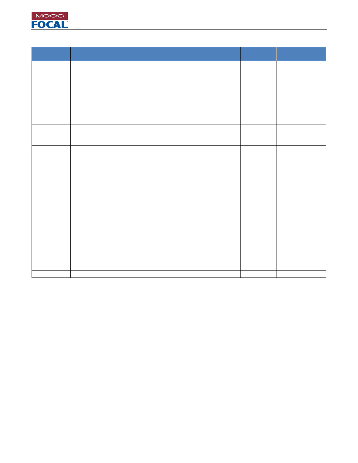
Document Revision History
Document
Revision
Details of Revision
Author(s)
Date
[yyyy-mm-dd]
Rev 1.0
Initial Release.
EM
2016-02-01
Rev 2.0
Release of B1 and C1 firmware
Ethernet Link Fault Pass Through
Trade HD-SDI for Gigabit Ethernet
Optional input of LED Header
Maximum 350Mb/s Ethernet throughput in M1 mode while
3G-SDI is plugged
3G-SDI Level B support
Update to colour coded diagnostic cable
EM
2016-06-27
Rev 3.0
Added sections
7.0 Firmware Updates
8.0 Feature Upgrades
EM
2016-10-13
Rev 4.0
Added sections
Quick Start Check List
Troubleshooting Section
VDX Expansion Card
EM
2017-07-24
Rev 5.0
Title change to 914-X Series Modular Multiplexer System
Added sections
Added System diagrams
Updated System Examples
EX Expansion Card
AX Expansion Card
HDV2 Media Converter
Optical Cards
Ribbon Cable
SFPs
Part Numbers
Dimensions
Stacking Instructions
EM
2018-09-12
Page 3
Model 914-X Series Modular Multiplexer System User Manual
Focal Technologies Corporation Page iii
A Moog Inc. Company Document Number: 914-0601-00 Rev. 5.0
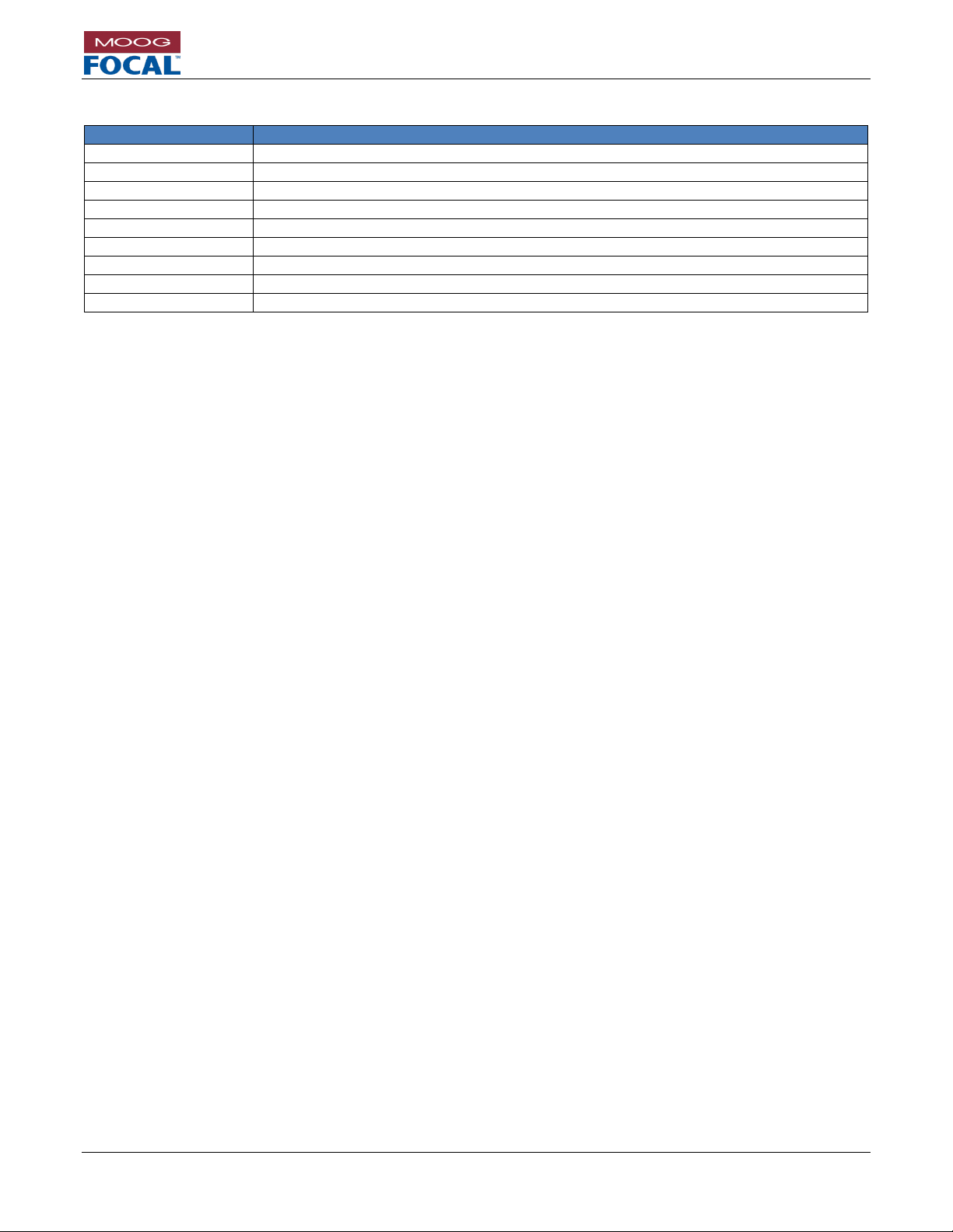
Reference Documents
Document Number
Document Title and Description
914-0401-00
Model 914 Diagnostic GUI
914-0415-00
Model 914 HDV2 Diagnostic GUI
914-0401-01
Model 914 Programmer
914-2016-00
Model 914-HDE Configuration Drawing
914-2018-00
Model 914-HDV2 Configuration Drawing
914-2020-00
Model 914-VDX Configuration Drawing
914-2022-00
Model 914-EX Configuration Drawing
914-2023-00
Model 914-AX Configuration Drawing
700-0271-00
AIB Plug-in Module User Guide
Page 4

Model 914-X Series Modular Multiplexer System User Manual
Focal Technologies Corporation Page iv
A Moog Inc. Company Document Number: 914-0601-00 Rev. 5.0
TABLE OF CONTENTS
1.0 Introduction ................................................................................................................................................. 1-1
1.1 Model 914-X Series Benefits ..................................................................................................................... 1-2
1.2 System Accessories and Options .............................................................................................................. 1-2
1.3 Safety Precautions .................................................................................................................................... 1-3
2.0 Setup Check List ......................................................................................................................................... 2-1
3.0 System Overview ........................................................................................................................................ 3-1
3.1 914-X Series System Card Options........................................................................................................... 3-1
3.2 Defining a 914-X Series System................................................................................................................ 3-2
3.3 System Specification ................................................................................................................................. 3-5
3.4 How to choose the optimal 914-X Series System Architecture ................................................................. 3-5
3.4.1 Example 914-X Series L1 System ...................................................................................................... 3-6
3.4.2 Example 914-X Series M1 System ..................................................................................................... 3-6
3.4.3 Example 914-X Series H1 System ...................................................................................................... 3-7
3.4.4 Choosing an Optical Card ................................................................................................................... 3-7
4.0 914-HDE Motherboard Overview ............................................................................................................... 4-1
4.1 914-HDE Versions ..................................................................................................................................... 4-1
4.2 914-HDE Power ......................................................................................................................................... 4-2
4.3 914-HDE HD Video Channel ..................................................................................................................... 4-3
4.4 914-HDE Serial Data Ports ........................................................................................................................ 4-4
4.5 914-HDE Ethernet Port .............................................................................................................................. 4-5
4.6 914-HDE Diagnostic LEDs ........................................................................................................................ 4-6
4.7 914-HDE Diagnostic LED Header ............................................................................................................. 4-7
4.8 914-HDE Optics ......................................................................................................................................... 4-8
4.8.1 914-HDE Flux Budget Calculation ...................................................................................................... 4-8
4.8.2 Optical Safety ...................................................................................................................................... 4-8
5.0 Model 914-X Series Diagnostic GUI .......................................................................................................... 5-1
5.1 Installing the Model 914-X Series Diagnostic GUI .................................................................................... 5-3
5.1.1 914-HDE Diagnostic Status Display ................................................................................................... 5-5
5.1.2 914-HDE Serial Port Configuration ..................................................................................................... 5-8
5.1.3 914-HDE Ethernet Port Configuration ................................................................................................. 5-9
6.0 914-X Series Expansion Cards .................................................................................................................. 6-1
6.1 914-VDX .................................................................................................................................................... 6-1
6.1.1 914-VDX Serial Data Ports ................................................................................................................. 6-2
6.1.2 914-VDX Composite Video Channels ................................................................................................. 6-1
6.1.3 914-VDX Power .................................................................................................................................. 6-2
6.1.4 914-VDX Diagnostic LEDs .................................................................................................................. 6-3
6.1.5 914-VDX Diagnostic LED Header ....................................................................................................... 6-4
6.1.6 914-VDX Expansion Channel Configuration ....................................................................................... 6-5
6.1.7 914-VDX Configuration ....................................................................................................................... 6-6
6.1.8 914-VDX Serial Port Configuration ..................................................................................................... 6-7
6.1.9 914-VDX Diagnostics .......................................................................................................................... 6-8
6.2 914-EX ....................................................................................................................................................... 6-9
6.2.1 914-EX Ethernet Ports ...................................................................................................................... 6-10
Page 5

Model 914-X Series Modular Multiplexer System User Manual
Focal Technologies Corporation Page v
A Moog Inc. Company Document Number: 914-0601-00 Rev. 5.0
6.2.2 914-EX Ethernet RJ45 LEDs ............................................................................................................ 6-11
6.2.3 914-EX Power ................................................................................................................................... 6-12
6.2.4 914-EX Diagnostic LEDs................................................................................................................... 6-13
6.2.5 914-EX Diagnostic LED Header ....................................................................................................... 6-14
6.2.6 914-EX Expansion Channel Configuration ....................................................................................... 6-15
6.2.7 914-EX Configuration ........................................................................................................................ 6-16
6.2.8 914-EX Ethernet Port Configuration ................................................................................................. 6-17
6.2.9 914-EX Diagnostics ........................................................................................................................... 6-18
6.3 914-AX ..................................................................................................................................................... 6-19
6.3.1 914-AX AIB Module Options ............................................................................................................. 6-19
6.3.2 914-AX AIB Module Installation ........................................................................................................ 6-20
6.3.3 914-AX Interface Connector ............................................................................................................. 6-21
6.3.4 914-AX Diagnostic LEDs................................................................................................................... 6-22
6.3.5 914-AX Diagnostic LED Header ....................................................................................................... 6-23
6.3.7 914-AX Configuration and Diagnostics ............................................................................................. 6-24
6.4 914-DX (Preliminary Information) ............................................................................................................ 6-25
6.5 Custom 914-X Series .............................................................................................................................. 6-25
7.0 914 Media Converters ................................................................................................................................. 7-1
7.1 914-HDV2 .................................................................................................................................................. 7-1
7.1.1 914-HDV2 Video Connections ............................................................................................................ 7-2
7.1.2 914-HDV2 Optical Connections .......................................................................................................... 7-2
7.1.3 914-HDV2 Power ................................................................................................................................ 7-4
7.1.4 914-HDV2 Configuration ..................................................................................................................... 7-5
7.1.5 914-HDV2 Diagnostic LED Header ..................................................................................................... 7-6
7.1.6 914-HDV2 Diagnostic LEDs ................................................................................................................ 7-7
7.1.7 914-HDV2 Diagnostics ........................................................................................................................ 7-8
8.0 914 Optical Cards ........................................................................................................................................ 8-1
8.1 914-CWDM ................................................................................................................................................ 8-1
8.2 914-CWDM-4R1 ........................................................................................................................................ 8-1
8.3 914-CWDM-8R .......................................................................................................................................... 8-1
8.4 914-SPLIT .................................................................................................................................................. 8-1
8.5 914-FOS .................................................................................................................................................... 8-1
9.0 Moog Focal Optical Transceivers ............................................................................................................. 9-1
10.0 914-X Series System Installation and Operation ................................................................................... 10-1
10.1 Installation ................................................................................................................................................ 10-1
10.2 Card Stacking .......................................................................................................................................... 10-2
10.3 914-X Series Expansion Interface Ribbon Cables .................................................................................. 10-3
10.4 914-X Series Bench Test ......................................................................................................................... 10-4
10.5 914-X Series Electrical and Environmental Specifications ...................................................................... 10-5
10.6 914-X Series Maintenance ...................................................................................................................... 10-5
10.7 914-X Series System Product Handling .................................................................................................. 10-7
10.8 914-X Series Accessories ....................................................................................................................... 10-7
10.9 914-X Series Dimensions ........................................................................................................................ 10-8
10.9.1 914-HDE ........................................................................................................................................... 10-8
10.9.2 914-VDX ............................................................................................................................................ 10-8
10.9.3 914-EX. ............................................................................................................................................. 10-9
Page 6

Model 914-X Series Modular Multiplexer System User Manual
Focal Technologies Corporation Page vi
A Moog Inc. Company Document Number: 914-0601-00 Rev. 5.0
10.9.4 914-AX. ............................................................................................................................................. 10-9
10.9.5 914-HDV2 ....................................................................................................................................... 10-10
10.10 Connector Part Numbers ....................................................................................................................... 10-11
10.11 Signal Specifications ............................................................................................................................. 10-12
11.0 Firmware Updates ..................................................................................................................................... 11-1
11.1 Firmware Compatibility ............................................................................................................................ 11-2
12.0 Feature Upgrades ..................................................................................................................................... 12-1
13.0 Part Numbers ............................................................................................................................................ 13-1
13.1 914-HDE Motherboard Part Numbers ..................................................................................................... 13-1
13.2 914-VDX Part Numbers ........................................................................................................................... 13-4
13.3 914-EX Part Numbers ............................................................................................................................. 13-5
13.4 914-AX Part Numbers ............................................................................................................................. 13-6
13.5 AIB Module Part Numbers ....................................................................................................................... 13-6
13.6 914-DX Part Numbers (Preliminary) ........................................................................................................ 13-7
13.7 914-HDV2 Part Numbers ......................................................................................................................... 13-8
13.8 914-X Series Optical Card Part Numbers ............................................................................................. 13-10
13.9 SFP Optical Transceiver Part Numbers ................................................................................................ 13-11
13.10 914-X Series High Speed Ribbon Cable Part Numbers ........................................................................ 13-13
14.0 Troubleshooting ........................................................................................................................................ 14-1
14.1 Moog Focal Technical Support Contact Information ............................................................................... 14-4
Page 7

Model 914-X Series Modular Multiplexer System User Manual
Focal Technologies Corporation Page vii
A Moog Inc. Company Document Number: 914-0601-00 Rev. 5.0
LIST OF TABLES
Table 3-1: 914-X Series System Modular Card List ............................................................................................... 3-1
Table 3-2: Signal Types and Required Bandwidths ............................................................................................... 3-5
Table 3-3: Available Bandwidth by Motherboard Card Version ............................................................................. 3-5
Table 3-4: Example 914-X Series L1 System Requirements ................................................................................. 3-6
Table 3-5: Example 914-X Series L1 System Solution .......................................................................................... 3-6
Table 3-6: Example 914-X Series M1 System Requirements ................................................................................ 3-6
Table 3-7: Example 914-X Series M1 System Solution ......................................................................................... 3-6
Table 3-8: Example 914-X Series H1 System Requirements ................................................................................ 3-7
Table 3-9: Example 914-X Series H1 System Solution .......................................................................................... 3-7
Table 4-1: 914-HDE Versions ................................................................................................................................. 4-1
Table 4-2: Power Connector Pinout ....................................................................................................................... 4-2
Table 4-3: Serial Data Port Numbering .................................................................................................................. 4-4
Table 4-4: Serial Data Connector Pinout ................................................................................................................ 4-4
Table 4-5: Ethernet LEDs ....................................................................................................................................... 4-5
Table 4-6: Ethernet Latency ................................................................................................................................... 4-5
Table 4-7: 914-HDE Diagnostic LEDs .................................................................................................................... 4-6
Table 4-8: 914-HDE Diagnostic LED Header Pinout .............................................................................................. 4-7
Table 4-9: Sample Flux Budget Calculation ........................................................................................................... 4-8
Table 5-1: J8 Diagnostic Connector Pinout ............................................................................................................ 5-2
Table 5-2: Diagnostic Connector Part Numbers ..................................................................................................... 5-2
Table 6-1: Serial Data Port Numbering .................................................................................................................. 6-2
Table 6-2: Serial Data Connector Pinout ................................................................................................................ 6-2
Table 6-3: Power Connector Pinout ....................................................................................................................... 6-2
Table 6-4: 914-VDX Diagnostic LEDs .................................................................................................................... 6-3
Table 6-5: 914-VDX Diagnostic LED Header Pinout .............................................................................................. 6-4
Table 6-6: 914-VDX Expansion Channel Configuration ......................................................................................... 6-5
Table 6-7: Ethernet Latency ................................................................................................................................. 6-10
Table 6-8: Ethernet LEDs ..................................................................................................................................... 6-11
Table 6-9: Power Connector Pinout ..................................................................................................................... 6-12
Table 6-10: 914-EX Diagnostic LEDs ................................................................................................................... 6-13
Table 6-11: 914-EX Diagnostic LED Header Pinout ............................................................................................ 6-14
Table 6-12: 914-EX Expansion Channel Configuration ........................................................................................ 6-15
Table 6-13: AIB Module Options .......................................................................................................................... 6-19
Table 6-14: 914-AX Interface Connector Pinouts ................................................................................................. 6-21
Table 6-15: 914-AX WAGO Connector Mating Plug ............................................................................................ 6-21
Table 6-16: 914-AX Diagnostic LEDs ................................................................................................................... 6-22
Table 6-17: 914-AX Diagnostic LED Header Pinout ............................................................................................ 6-23
Table 7-1: Power Connector Pinout ....................................................................................................................... 7-4
Table 7-2: SW1 - SFP Transmitter Disable Non-MSA Mode ................................................................................. 7-5
Table 7-3: SW3 - SFP Transmitter Disable MSA Mode ......................................................................................... 7-5
Table 7-4: SW4 and SW5 Factory Programming Mode ......................................................................................... 7-5
Table 7-5: SW7 - DIAGNOSTICS IN MSA OR NON-MSA ..................................................................................... 7-6
Table 7-6: SW2 (Channel 1) and SW6 (Channel 2): Input EQ or Output Cabled Driver Settings ......................... 7-6
Table 7-7: 914-HDV2 Diagnostic LED Header J7 Pinout ....................................................................................... 7-6
Table 7-8: 914-HDV2 Diagnostic LEDs .................................................................................................................. 7-7
Table 9-1: SFP Optical Transceiver Options .......................................................................................................... 9-1
Table 10-1: Electrical Specification ...................................................................................................................... 10-5
Table 10-2: Environmental Specification .............................................................................................................. 10-5
Table 10-3: Connector Part Numbers ................................................................................................................. 10-11
Table 10-4: Signal Specifications ....................................................................................................................... 10-12
Table 11-1: Firmware Revisions ........................................................................................................................... 11-2
Table 13-1: 914-HDE Part Numbers .................................................................................................................... 13-1
Table 13-2: 914-HDE Included Accessories ........................................................................................................ 13-1
Table 13-3: 914-HDE CWDM Options.................................................................................................................. 13-2
Table 13-4: 914-HDE Factory Versions................................................................................................................ 13-2
Table 13-5: 914-HDE Factory Configurations ...................................................................................................... 13-3
Page 8

Model 914-X Series Modular Multiplexer System User Manual
Focal Technologies Corporation Page viii
A Moog Inc. Company Document Number: 914-0601-00 Rev. 5.0
Table 13-6: 914-VDX Part Numbers ..................................................................................................................... 13-4
Table 13-7: 914-VDX Included Accessories ......................................................................................................... 13-4
Table 13-8: 914-VDX Factory Configuration Options ........................................................................................... 13-4
Table 13-9: 914-EX Part Numbers ....................................................................................................................... 13-5
Table 13-10: 914-EX Included Accessories ......................................................................................................... 13-5
Table 13-11: 914-EX Factory Configuration Options ........................................................................................... 13-5
Table 13-12: 914-AX Part Numbers ..................................................................................................................... 13-6
Table 13-13: 914-AX Included Accessories ......................................................................................................... 13-6
Table 13-14: AIB Module Part Numbers............................................................................................................... 13-6
Table 13-15: 914-DX Part Numbers ..................................................................................................................... 13-7
Table 13-16: 914-DX Included Accessories ......................................................................................................... 13-7
Table 13-17: 914-DX Factory Configuration Options ........................................................................................... 13-7
Table 13-18: 914-HDV2 Part Numbers ................................................................................................................ 13-8
Table 13-19: 914-HDV2 Included Accessories .................................................................................................... 13-9
Table 13-20: 914-HDV2 CWDM Options ............................................................................................................. 13-9
Table 13-21: 914 Optical Card Part Numbers .................................................................................................... 13-10
Table 13-22: 914 Standard Optical SFP Part Numbers ..................................................................................... 13-11
Table 13-23: 914 Pressure Tolerant Optical SFP Part Numbers ....................................................................... 13-12
Table 13-24: 914-X Series High Speed Ribbon Cable Part Numbers ............................................................... 13-13
Table 13-25: 914-X Series High Speed Ribbon Cable Included Accessories.................................................... 13-13
Page 9

Model 914-X Series Modular Multiplexer System User Manual
Focal Technologies Corporation Page ix
A Moog Inc. Company Document Number: 914-0601-00 Rev. 5.0
LIST OF FIGURES
Figure 1-1: 914-X Series HDE Motherboard .......................................................................................................... 1-1
Figure 1-2: 914-X Series System with Stacked Expansion Cards ......................................................................... 1-1
Figure 1-3: 914-X Series System with Tethered Expansion Cards ........................................................................ 1-1
Figure 3-1: 914-HDE Motherboard ......................................................................................................................... 3-2
Figure 3-2: 914-X Series System with Expansion Cards ....................................................................................... 3-3
Figure 3-3: 914 4-CH CWDM Card ........................................................................................................................ 3-3
Figure 3-4: 914-X Series System with 914-HDV2 and CWDM .............................................................................. 3-4
Figure 4-1: 914-HDE Top View .............................................................................................................................. 4-1
Figure 4-2: Power Input Connector Location .......................................................................................................... 4-2
Figure 4-3: Mini SMB Jack - Amphenol P/N 142146-75 ......................................................................................... 4-3
Figure 4-4: Video Channel 1 Connector Location .................................................................................................. 4-3
Figure 4-5: Molex Micro-fit P/N 43045-0800 .......................................................................................................... 4-4
Figure 4-6: Serial Ports 1 and 2 .............................................................................................................................. 4-4
Figure 4-7: Ethernet Port ........................................................................................................................................ 4-5
Figure 4-8: Diagnostic LEDs ................................................................................................................................... 4-6
Figure 4-9: External LED Circuit Diagram .............................................................................................................. 4-7
Figure 4-10: Diagnostic LED Header...................................................................................................................... 4-7
Figure 5-1: Basic Diagnostics Setup ...................................................................................................................... 5-1
Figure 5-2: 914-HDE Diagnostic Interface Cable ................................................................................................... 5-1
Figure 5-3: 914-HDE Diagnostic Connector ........................................................................................................... 5-2
Figure 5-4: Diagnostic GUI Start Screen ................................................................................................................ 5-3
Figure 5-5: 914-HDE Card Info ............................................................................................................................... 5-4
Figure 5-6: 914-HDE Voltage and Junction Temperature Information ................................................................... 5-5
Figure 5-7: 914-HDE Optical Link Status ............................................................................................................... 5-6
Figure 5-8: 914-HDE Signal Status ........................................................................................................................ 5-7
Figure 5-9: 914-HDE Serial Port Configuration ...................................................................................................... 5-8
Figure 5-10: 914-HDE Ethernet Settings ................................................................................................................ 5-9
Figure 6-1: 914-VDX ............................................................................................................................................... 6-1
Figure 6-2: Molex Micro-fit ...................................................................................................................................... 6-2
Figure 6-3: VDX Serial Ports .................................................................................................................................. 6-2
Figure 6-4: Mini SMB Jack - Amphenol P/N 142146-75 ......................................................................................... 6-1
Figure 6-5: Video Connector Locations .................................................................................................................. 6-1
Figure 6-6: Power Input Connector Location .......................................................................................................... 6-2
Figure 6-7: VDX Diagnostic LEDs .......................................................................................................................... 6-3
Figure 6-8: Diagnostic LED Header ........................................................................................................................ 6-4
Figure 6-9: Diagnostic LED Header ........................................................................................................................ 6-5
Figure 6-10: SW1 Position and Orientation ............................................................................................................ 6-5
Figure 6-11: 914-VDX Video Configuration ............................................................................................................ 6-6
Figure 6-12: 914-VDX Serial Port Configuration .................................................................................................... 6-7
Figure 6-13: 914-VDX Voltages and Temperature ................................................................................................. 6-8
Figure 6-14: 914-EX ............................................................................................................................................... 6-9
Figure 6-15: Ethernet Ports .................................................................................................................................. 6-11
Figure 6-16: Factory Power Input Connector Location ......................................................................................... 6-12
Figure 6-17: 914-EX Diagnostic LEDs .................................................................................................................. 6-13
Figure 6-18: Diagnostic LED Header.................................................................................................................... 6-14
Figure 6-19: Diagnostic LED Header.................................................................................................................... 6-15
Figure 6-20: SW1 Position and Orientation .......................................................................................................... 6-15
Figure 6-21: 914-EX Location Configuration ........................................................................................................ 6-16
Figure 6-22: 914-EX Ethernet Port Configuration ................................................................................................ 6-17
Figure 6-23: 914-EX Ethernet Port Link Status .................................................................................................... 6-17
Figure 6-24: 914-EX Voltages and Temperature ................................................................................................. 6-18
Figure 6-25: 914-AX ............................................................................................................................................. 6-19
Figure 6-26: 914-AX with AIB-232 Module (example) .......................................................................................... 6-19
Figure 6-27: AIB Module Orientation .................................................................................................................... 6-20
Figure 6-28: 914-AX WAGO Connector ............................................................................................................... 6-21
Figure 6-29: 914-AX Diagnostic LEDs .................................................................................................................. 6-22
Page 10

Model 914-X Series Modular Multiplexer System User Manual
Focal Technologies Corporation Page x
A Moog Inc. Company Document Number: 914-0601-00 Rev. 5.0
Figure 6-30: 914-AX Diagnostic LED Header ...................................................................................................... 6-23
Figure 6-31: 914-AX Data Activity ........................................................................................................................ 6-24
Figure 7-1: 914-HDV2............................................................................................................................................. 7-1
Figure 7-2: 914-HDV2 Interface Locations and Pin Numbering ............................................................................. 7-2
Figure 7-3: Mini SMB Jack - Amphenol P/N 142146-75 ......................................................................................... 7-2
Figure 7-4: Video I/O Locations .............................................................................................................................. 7-2
Figure 7-5: 914-HDV2 Optical Interface ................................................................................................................. 7-3
Figure 7-6: Power Input Connector Location .......................................................................................................... 7-4
Figure 7-7: 914-HDV2 Configuration Dip Switches ................................................................................................ 7-5
Figure 7-8: 914-HDV2 Diagnostic LEDs and LED Header ..................................................................................... 7-7
Figure 7-9: 914-HDV2 Optical Diagnostics............................................................................................................. 7-8
Figure 7-10: 914-HDV2 PCBA Diagnostics ............................................................................................................ 7-9
Figure 7-11: 914-HDV2 Video Diagnostics ............................................................................................................ 7-9
Figure 7-12: 914-HDV2 LED Diagnostics ............................................................................................................... 7-9
Figure 10-1: 914-HDE Dimensions ....................................................................................................................... 10-1
Figure 10-2: 914-X Series System Stack ............................................................................................................. 10-2
Figure 10-3: 914-X Series Expansion Interface High Speed Ribbon Cable......................................................... 10-3
Figure 10-4: 914-X Series Linear (inline) Layout .................................................................................................. 10-3
Figure 10-5: 914-X Series System Dual Stack (side-to-side) Layout ................................................................... 10-3
Figure 10-6: LC connector .................................................................................................................................... 10-6
Figure 10-7: ST connector .................................................................................................................................... 10-6
Figure 10-8: SFP Transceiver (Dual LC) .............................................................................................................. 10-7
Figure 10-9: 914-HDE Dimensions ....................................................................................................................... 10-8
Figure 10-10: 914-VDX Dimensions ..................................................................................................................... 10-8
Figure 10-11: 914-EX Dimensions ....................................................................................................................... 10-9
Figure 10-12: 914-AX Dimensions ....................................................................................................................... 10-9
Figure 10-13: 914-HDV2 Dimensions................................................................................................................. 10-10
Figure 11-1: Firmware Update GUI ...................................................................................................................... 11-1
Figure 12-1: Feature Update Via Configuration Tool ........................................................................................... 12-1
Page 11
Model 914-X Series Modular Multiplexer System User Manual
Focal Technologies Corporation Page xi
A Moog Inc. Company Document Number: 914-0601-00 Rev. 5.0
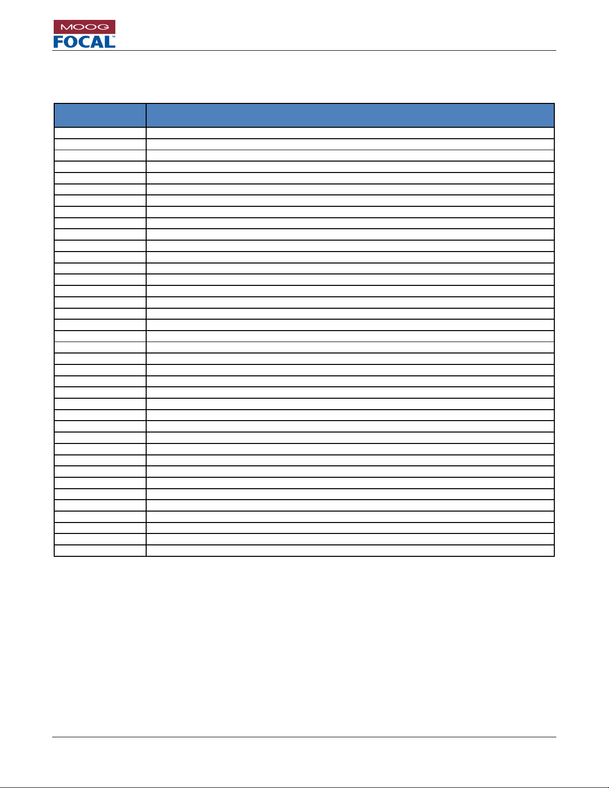
ACRONYMS AND ABBREVIATIONS
The list below contains the acronyms and abbreviations used in this user's guide.
ACRONYM /
ABBREVIATION
DESCRIPTION
AIB
Adaptable Interface Board
AX
AIB EXpansion Adaptor Card
3G
3 Gbps HD Video
BER
Bit Error Rate
CWDM
Coarse Wavelength Division Multiplexer / Multiplexing
DX
Serial Data EXpansion
EIA
Electronic Industries Association
ESD
Electrostatic Discharge
EX
Ethernet EXpansion
FORJ
Fiber Optic Rotary Joint
FPGA
Field Programmable Gate Array
GBE
Gigabit Ethernet
Gbps
Gigabits Per Second
HD
High Definition
HS
High Speed
HDE
HD-Video, Serial Data, Ethernet
HDV2
Dual (2) HD Video
I/O
Input/output
kbps
Kilobits Per Second
LC/PC
Lucent Connector / Physical Contact
LED
Light Emitting Diode
LS
Low Speed
Mbps
Megabits Per Second
MDI/MDIX
Automatic medium-dependent interface crossover
MS
Medium Speed
P/N
Part Number
PCB
Printed Circuit Board
PCBA
Printed Circuit Board Assembly
PPS
Pulse Per Second
SD
Standard Definition
SDI
Serial Digital Interface
SFP
Small Form-factor Pluggable (Optical Transceiver)
SMT
Surface Mount Technology
TDM
Time Division Multiplexer / Multiplexing
TTL
Transistor-Transistor Logic
VDX
Composite Video, Serial Data, EXpansion
VOAT
Variable Optical Attenuator
WDM
Wavelength Division Multiplexer / Multiplexing
Page 12

Model 914-X Series Modular Multiplexer System User Manual
Focal Technologies Corporation Page 1-1
A Moog Inc. Company Document Number: 914-0601-00 Rev. 5.0
1.0 Introduction
The Focal Model 914-X Series Modular Multiplexer System is a compact and rugged video, data and Ethernet
multiplexer and fiber optic transmission system designed for industrial environments and other applications
requiring the transmission of HD video, serial data and Ethernet over an optical link. The 914-X Series has been
optimized for low power operation and delivery of low latency, uncompressed video and Ethernet data.
A series of expansion cards are available, allowing additional composite video channels, serial data channels,
Ethernet ports, as well as many specialty signals such as TTL, hydrophone, CAN bus and custom sonars to be
added to any 914-X Series system without requiring extra fibers or wavelengths.
The rich feature set and vast signal options are packaged in an incredibly small form factor. The credit card size,
along with the geometry and location of the connectors allow the 914-X Series multiplexers to be installed in very
small enclosures. Multiple card systems can be configured either as stacks, or via flexible high speed ribbon cable
providing even further installation flexibility.
This manual provides 914-X Series system users with detailed information relevant to the design,
configuration, installation, and operation of the 914-X Series system. This manual and the appropriate
reference documents should be reviewed prior to installation or configuration of the multiplexer system.
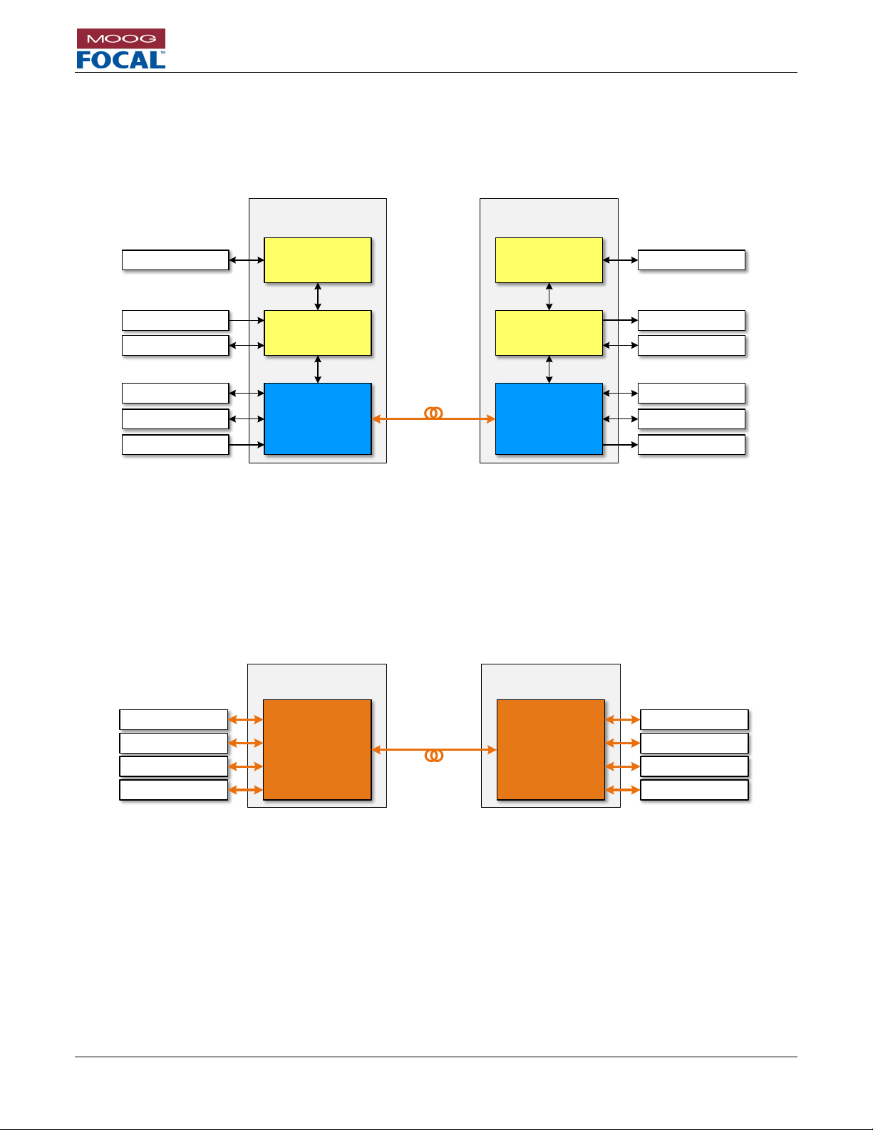
The figures below show different configurations and stacking options of the 914-X series. On the left, the 914-HDE
motherboard is shown stand-alone. On the right, the 914-HDE and expansion cards (914-EX, VDX and AX-232)
are shown stacked together and held into place via standoffs. At the bottom, a similar stack is shown but with a
high-speed ribbon cable to accommodate applications such as bottles or low profile enclosures.
Figure 1-1: 914-X Series HDE Motherboard
Figure 1-2: 914-X Series System with Stacked
Expansion Cards
Figure 1-3: 914-X Series System with Tethered Expansion Cards
Page 13

Model 914-X Series Modular Multiplexer System User Manual
Focal Technologies Corporation Page 1-2
A Moog Inc. Company Document Number: 914-0601-00 Rev. 5.0
1.1 Model 914-X Series Benefits
Modular Design, configured to custom requirements
Very high bandwidth optical options replace many lower speed options.
High budget optics allow for extended link distances
Extremely small size will fit in cost effective enclosure systems
Upgrade and add features or cards when required.
Low cost of spare parts
Full diagnostics provided with an advanced GUI included with every system
Software configuration of features and settings
Software configurable multi-protocol serial ports.
Non-switched Ethernet ports guaranteeing throughput without collisions in real time
Full bandwidth real time video, no compression, no compromises
Latency for all signals is measured in micro-seconds
Simple integration of complex systems with user friendly instructions, Moog Focal direct support when
required
Custom OEM options available
1.2 System Accessories and Options
Included:
Mounting Hardware
Pigtailed diagnostic (RS232) plug and wires
Pigtailed power plug and cable for the 914-HDE Motherboard.
Modules individually packaged with configuration drawings
914-0401-00 Diagnostic GUI – downloadable from www.moog.com/focal/914-x-series
Default configuration settings
Moog Focal direct support
Optional:
Fiber jumpers and attenuators
Mating connectors and plugs
Thermal gap pad material
Extended factory testing
Factory custom configuration
Factory multi-card system integration, build and testing
Enclosure options:
o Pressure bottles
o 19” racks with diagnostic LEDs
o Custom enclosures for OEM
Page 14

Model 914-X Series Modular Multiplexer System User Manual
Focal Technologies Corporation Page 1-3
A Moog Inc. Company Document Number: 914-0601-00 Rev. 5.0
1.3 Safety Precautions
The following safety precautions should be observed before using this product.
This product is intended for use by qualified personnel who recognize shock hazards and
are familiar with safety precautions required to avoid possible injury. Do not make module
connections unless qualified to do so.
Before connecting this product to the power source, verify that the output voltage is within
the specifications of the product’s power supply.
Do not attempt to modify or repair any circuit unless recommended by the manufacturer.
Protect the power cable from being walked on or pinched by items placed or against them.
Always unplug the power cable at the plug, do not pull on the cord itself.
Do not block any ventilation openings.
Do not look into the end of a fiber when it is plugged into a transceiver or active fiber,
especially when using a magnifying instrument, such as a fiber microscope.
Handle optical fiber with extreme care. Glass fiber is subject to breakage if mishandled.
Page 15

Model 914-X Series Modular Multiplexer System User Manual
Focal Technologies Corporation Page 2-1
A Moog Inc. Company Document Number: 914-0601-00 Rev. 5.0
2.0 Setup Check List
The purpose of this section is to provide a check list that can be followed to setup 914-X Series systems both
physically and through electronic configuration. Details regarding each step can be found in this manual via the
referenced section links.
1. Expansion cards:
a. Set dip switch to appropriate setting, refer to Section 6.1.6.
i. The (bottom) card closest to the 914-HDE should be set to OFF, OFF (Expansion 1).
2. Mounting cards:
a. 5/32” (4 mm) minimum clearance under the 914-HDE. (included standoff P/N EL-M0260)
b. 21/32” (16.67 mm) nominal standoffs of 2-56 type between cards. (included standoff P/N EL-M0247)
c. All 914-X Series cards provide electrically isolated conductive cooling via the mounting holes.
d. Thermal gap material (optional P/N 914-0118-00) to provide conductive cooling to an enclosure should be placed under
the 914-HDE.
e. Stacking order is 914-HDE on bottom, then medium speed (MS) expansion cards directly above, ending with low speed
(LS) expansion cards on top. Media Converters and optical cards do not require electrical connection via the expansion
connector, they can be the furthest away from the 914-HDE.
f. Refer to Section 10.1.
3. Connect console to remote via LC to LC fiber jumper. For short links, attenuation is required. 10 dB is the suggested
minimum attenuation in the fiber link. For flux budget calculations refer to Section 4.8.1.
4. Connect the diagnostic port of the console 914-HDE to a computer using either the local COM port or a serial-to-USB
converter. Install and run the 914 Diagnostic GUI. Refer to Section 5.0.
5. Connect the 914-HDE to a DC power supply with 5 V to 12 V power. Refer to Section 4.2. All power LEDs on each card
should be lit green. Verify all system voltages in the 914 Diagnostic GUI. Refer to Section 5.0.
6. Configure all cards (except 914-AX) via Diagnostic GUI:
a. Configure console HDE
i. Serial protocol. Refer to Section 5.1.2.
ii. Ethernet auto-negotiate settings. Refer to Section 0.
b. Configure console VDX
i. Set as console. Refer to Section 6.1.7.
ii. Set video direction to input. Refer to Section 6.1.7.
iii. Set serial protocol. Refer to Section 6.1.8.
c. Configure console EX
i. Set as console. Refer to Section 6.1.7.
ii. Set Ethernet speed and negotiation. Refer to Section 6.1.7.
d. Configure remote HDE
i. Serial protocol. Refer to Section 5.1.2.
ii. Ethernet auto-negotiate settings. Refer to Section 0.
e. Configure remote VDX
i. Set as remote. Refer to Section 6.1.7.
ii. Set video direction to output. Refer to Section 6.1.7.
iii. Set serial protocol. Refer to Section 6.1.8.
f. Configure remote EX
i. Set as remote. Refer to Section 6.1.7.
ii. Set Ethernet speed and negotiation. Refer to Section 6.1.7.
g. Turn the power off, wait 10 seconds and power up again. Confirm the settings are correct using the 914 Diagnostic
GUI.
7. Connect video, Ethernet and serial as required. Verify status and activity in the 914 Diagnostic GUI.
a. HD Video – Refer to Section 4.3.
b. Ethernet – Refer to Section 4.5.
c. Serial– Refer to Section 4.4.
d. Composite video – Refer to Section 6.1.2.
8. Perform bench level testing to verify links. Refer to troubleshooting Section 14.0.
9. Install cards in system, ensure good thermal contact via mounting hardware, thermal gap pads, and heat spreaders. Refer
to Section 10.0.
10. Verify and monitor the FPGA and SFP temperatures and voltages during operation using the 914 Diagnostic GUI. All values
should remain in green.
Page 16

Model 914-X Series Modular Multiplexer System User Manual
Focal Technologies Corporation Page 3-1
A Moog Inc. Company Document Number: 914-0601-00 Rev. 5.0
3.0 System Overview
3.1 914-X Series System Card Options
Users can combine the modular 914-X Series cards into complex fiber optic telemetry systems.
914-X Series cards are sorted into 4 basic categories:
1. Motherboards: Have optical transceivers and multiplex various different data types into a single data
stream over fiber. This is the foundation to any multiplexing system, they provide expansion channels for
expansion card integration.
a. Card(s): 914-HDE.
2. Expansion Cards: Add more signal interfaces to the motherboard. They draw power from the
motherboard and do not require their own optical transceiver. They do not operate on their own. They
require one or more low speed (LS) or medium speed (MS) expansion channels on a motherboard to
operate.
a. Card(s): 914-VDX, 914-EX, 914-DX and 914-AX.
3. Media Converters: Convert a single data type to fiber, usually in a 1:1 signal to optical wavelength
conversion. Can operate stand-alone, or can be optically combined with other multiplexers or media
converters.
a. Card(s): 914-HDV2.
4. Optical Cards: Combine multiple optical wavelengths onto a single fiber, or create optical
redundancies for increased system reliability.
a. Cards: 914-CWDM, 914-CWDM-4, 914-CWDM-8, 914-SWITCH, 914-FOS
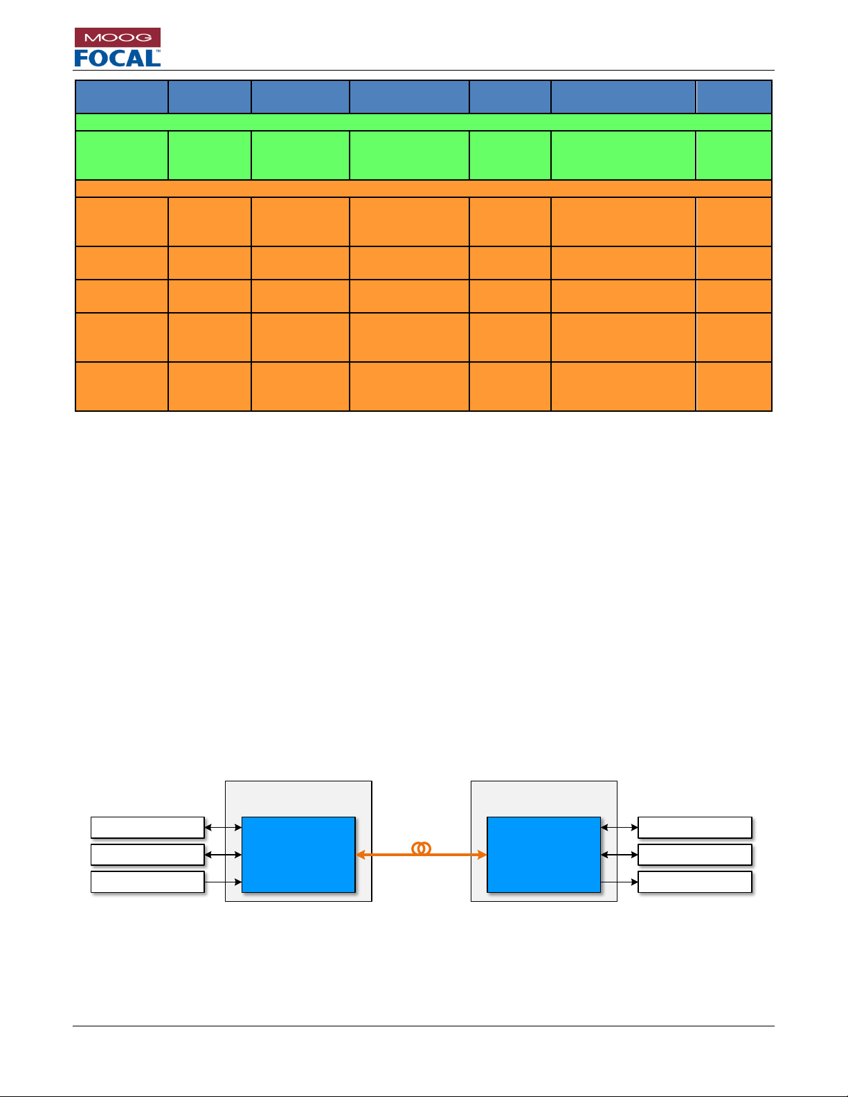
Table 3-1: 914-X Series System Modular Card List
Card ID
Ethernet
Video
Serial Data
Other
Optics
Expansion
channels
Motherboards
914-HDE L1
1x
10/100 Mb/s
1x
HD/SD-SDI
2x
RS232/485/422
Requires 2
wavelengths: Uplink
and Downlink
4x LS
914-HDE M1
1x
10/100/1000
Mb/s
1x
3G/HD/SD-
SDI
2x
RS232/485/422
Requires 2
wavelengths: Uplink
and Downlink
4x LS
4x MS
914-HDE H1
1x
10/100/1000
Mb/s
1x
3G/HD/SD-
SDI
2x
RS232/485/422
Requires 2
wavelengths: Uplink
and Downlink
4x LS
4x MS
Expansion Cards
914-VDX
2x
NTSC/PAL
4x
RS232/485/422
Via 914-HDE
1x MS
914-EX
2x
10/100/1000
Mb/s
Via 914-HDE
1x MS
(2x MS
Optional)
914-AX
w/914-AIB
1x Isolated
RS232 or
RS485 or
RS422
TTL
MS900
ARCnet
Hydrophone
CAN bus
Via 914-HDE
w/914-AIB installed on
914-AX
1x LS
914-DX
6x
RS232/485/422
Via 914-HDE
1x LS
Page 17
Model 914-X Series Modular Multiplexer System User Manual
Focal Technologies Corporation Page 3-2
A Moog Inc. Company Document Number: 914-0601-00 Rev. 5.0
Card ID
Ethernet
Video
Serial Data
Other
Optics
Expansion
channels
Media Converters
914-HDV2
2x
3G/HD/SD-
SDI
Requires 1
wavelength per video
channel
None
Optical Cards
914 CWDM
2 wavelengths +
1310/1550 bypass to
single fiber
N/A
914 4Ch
CWDM
4 wavelengths to
single fiber
N/A
914 8Ch
CWDM
8 wavelengths to
single fiber
N/A
914-SWITCH
Splits the optical feed
to two fibers for
redundancy
N/A
914-FOS
Selects between two
redundant optical
fibers.
N/A
3.2 Defining a 914-X Series System
914-X Series systems are used as pairs (one remote and one console) to provide a transparent video, data and
Ethernet link over optical fiber(s). The installed optical transceivers determine the maximum optical link speed, fiber
type, number of fibers (1 or 2), and link distance. The card version sets the operational bandwidth, which is
independent from the optical data rate. The optical link uses a proprietary data protocol ensuring reliable
transmission with extremely low latency using highly efficient and dynamic bandwidth utilization.
Typically, the uplink (remote to console) and downlink (console to remote) are combined on a single fiber –
multimode or singlemode (standard) – with a passive optical coupler known as a Wavelength Division Multiplexer
(WDM). The WDM is integrated in the optical transceiver. Standard, single fiber systems operate with 1310 nm
uplink and 1550 nm downlink wavelengths. In larger systems, multiple 914-X Series stacks may be combined on a
single fiber using a Coarse Wavelength Division Multiplexer (CWDM) to take advantage of the high bandwidth of
optical fiber.
Figure 3-1 illustrates an example of a simple 914-X Series system configuration using a standard, standalone 914HDE motherboard, which supports the multiplexing of one (1) 3G/HD/SD-SDI channels, two (2) bidirectional RS232 / RS-485 / RS-422 serial data channels and one (1) Gigabit Ethernet channel over a single optical fiber. This
is the base card of any 914-X Series system.
Figure 3-1: 914-HDE Motherboard
Note that the HD video source (e.g. from an HD camera) is connected at the remote end. The HD video output is
provided at the console end (e.g. to an HD monitor).
Focal 914-X Series
System
Focal 914-X Series
System
914-HDE
HD Video, Ethernet
and Serial
Motherboard
Host Electronics
(Remote)
914-HDE
HD Video, Ethernet
and Serial
Motherboard
Multiple Serial
HD Video
Host Electronics
(Console)
Optical Fiber
Multiple Serial
Ethernet
HD Video
Ethernet
Page 18
Model 914-X Series Modular Multiplexer System User Manual
Focal Technologies Corporation Page 3-3
A Moog Inc. Company Document Number: 914-0601-00 Rev. 5.0
The external fiber optic system includes optical components such as optical connectors and a Fiber Optic Rotary
Joint (FORJ).
An expansion connector on the 914-HDE supports 8 expansion card ports: 4 low speed (LS) and 4 medium speed
(MS) ports. Expansion cards allow a full system to be built using the 914-HDE Motherboard as the base optical
card. Optional expansion cards are detailed in Section 6.0.
Figure 3-2: 914-X Series System with Expansion Cards
Figure 3-2 shows a 914-X Series system with both 914-VDX and 914-EX expansion cards added. These cards
stack on top of the 914-HDE motherboard providing more video, Ethernet and serial data channels. No extra optical
components are required for these additional expansion cards.
For larger systems requiring more optical bandwidth than a single 914-X Series stack can provide, Moog Focal has
a series of CWDM products that allow many optical data streams to be combined onto a single fiber. These cards
can handle the addition of 2, 4, 6, 8 or more systems onto a single fiber.
Figure 3-3 shows a simple 4 channel CWDM that would combine 4 optical wavelengths onto a single fiber.
Figure 3-3: 914 4-CH CWDM Card
Focal 914-X Series
System
Focal 914-X Series
System
914-HDE
HD Video, Ethernet
and Serial
Motherboard
914-VDX
Video and Serial
Expansion
Multiple Serial
Host Electronics
(Remote)
914-HDE
HD Video, Ethernet
and Serial
Motherboard
Multiple Serial
HD Video
Host Electronics
(Console)
Optical Fiber
Multiple Serial
Ethernet
HD Video
Ethernet
Multiple Video
914-EX
Ethernet Expansion
Multiple Ethernet
914-EX
Ethernet Expansion
914-VDX
Video and Serial
Expansion
Multiple Serial
Multiple Video
Multiple Ethernet
Focal 914-X Series
CWDM
Focal 914-X Series
CWDM
Host Electronics
(Remote)
Host Electronics
(Console)
4 Channel CWDM,
Red
Optical Fiber
1531 nm
1511 nm
1491 nm
1471 nm
4 Channel CWDM,
Red
1531 nm
1511 nm
1491 nm
1471 nm
Page 19

Model 914-X Series Modular Multiplexer System User Manual
Focal Technologies Corporation Page 3-4
A Moog Inc. Company Document Number: 914-0601-00 Rev. 5.0
Figure 3-4 shows how a 914-X Series system can be combined with the 914-HDV2 media converter using a 4
channel CWDM.
This example system has 3 HD video channels, 2 NTSC/PAL channels, 3 Gigabit Ethernet channels and 6 serial
data channels all combined in real time onto a single bi-directional fiber link.
Figure 3-4: 914-X Series System with 914-HDV2 and CWDM
Focal 914-X Series
System
Focal 914-X Series
System
Multiple Serial
Host Electronics
(Remote)
Multiple Serial
HD Video
Host Electronics
(Console)
Multiple Serial
Ethernet
HD Video
Ethernet
Multiple Video
Multiple Ethernet
Multiple Serial
Multiple Video
Multiple Ethernet
Multiple HD Video
Optical Fiber
Multiple HD Video
914-CWDM
Optical Mux/Demux
914-HDE
HD Video, Ethernet
and Serial
Motherboard
914-HDE
HD Video, Ethernet
and Serial
Motherboard
914-VDX
Video and Serial
Expansion
914-EX
Ethernet Expansion
914-HDV2
Dual HD Video
Media Converter
914-CWDM
Optical Mux/Demux
914-HDV2
Dual HD Video
Media Converter
914-EX
Ethernet Expansion
914-VDX
Video and Serial
Expansion
Page 20
Model 914-X Series Modular Multiplexer System User Manual
Focal Technologies Corporation Page 3-5
A Moog Inc. Company Document Number: 914-0601-00 Rev. 5.0
3.3 System Specification
When specifying a 914-X Series system, it is important to ensure there is enough available optical bandwidth to
support the signals and data throughput required. Moog Focal has released three versions of the 914-HDE
motherboard with pricing linked to bandwidth. This allows customers who do not require expansion cards, 3G-SDI,
or gigabit Ethernet to specify a more cost effective solution. Moog Focal can work with customers to configure a
complete optical multiplexer solution, and the following section shows signal bandwidths and sample system
configurations. This allows customers to weigh the tradeoffs between system bandwidth, cost, size and power,
while also showing the upgrade potential of any 914-X Series system.
Table 3-2: Signal Types and Required Bandwidths
Signal type or expansion card
Required Bandwidth
914-HDE base bandwidth for serial channels,
diagnostics, and all low speed (LS) expansion
channels
150 Mb/s
(Always Enabled)
914-VDX base bandwidth (serial channels)
50 Mb/s total per card (Always Enabled)
10 Mb/s Ethernet
Up to 10 Mb/s
100 Mb/s Ethernet
Up to 100 Mb/s
1000 Mb/s Ethernet
Up to 1000 Mb/s
SD-SDI
300 Mb/s
HD-SDI
1550 Mb/s
3G-SDI
3050 Mb/s
Analog video (NTSC or PAL)
250 Mb/s per video channel
914-DX
0 Mb/s
Included with 914-HDE base bandwidth
914-AX
0 Mb/s
Included with 914-HDE base bandwidth
Table 3-3: Available Bandwidth by Motherboard Card Version
914-HDE Version
Available Bandwidth
Expansion Channels Supported
L1
1800 Mb/s
4 low speed channels
M1
3500 Mb/s
4 low speed channels
4 medium speed channels
H1
5600 Mb/s
4 low speed channels
4 medium speed channels
Using the above two tables as a reference, it becomes possible to specify a full system and ensure a lossless, low
latency optical link.
3.4 How to choose the optimal 914-X Series System Architecture
1. Calculate the bandwidth of the required signals based on Table 3-2.
2. Choose the 914-HDE motherboard version based on required bandwidth. Multiple 914-X Series systems
may be required for very high bandwidth applications. Refer to Table 3-3.
3. Consider using 914-HDV2 for systems requiring more than one HD video channel.
4. Choose 914 expansion card(s) with the required number and type of interfaces required.
5. Ensure the base bandwidths for the 914-HDE and any 914-VDX cards are included with the bandwidth
calculations.
6. Verify expansion channels available vs required, refer to Table 3-1.
7. Balance expansion cards between motherboards in very large systems.
Page 21
Model 914-X Series Modular Multiplexer System User Manual
Focal Technologies Corporation Page 3-6
A Moog Inc. Company Document Number: 914-0601-00 Rev. 5.0
3.4.1 Example 914-X Series L1 System
Table 3-4: Example 914-X Series L1 System Requirements
Quantity
Required Signal
Bandwidth
1
HD-SDI video
1550 Mb/s
8
Serial channels
150 Mb/s (914-HDE base
bandwidth)
1
CAN bus
Included
1
Hydrophone
Included
1
Fast Ethernet channel
100 Mb/s
Total
1800 Mb/s (= Max L1 bandwidth)
Table 3-5: Example 914-X Series L1 System Solution
Required Card
Quantity
Signals
Expansion Channels
914-HDE (L1)
1
1 x HD-SDI
2 x Serial
1 x Fast Ethernet
4 x Low speed available
914-DX
1
6 x Serial channels (6 per Card)
1 x Low speed
914-AX with AIB-CANBUS
1
1 x CAN bus
1 x Low speed
914-AX with AIB-HYDRO
1
1 x Hydrophone
1 x Low speed
3.4.2 Example 914-X Series M1 System
Table 3-6: Example 914-X Series M1 System Requirements
Quantity
Required Signal
Bandwidth
1
HD-SDI video
1550 Mb/s
18
Serial channels
200 Mb/s (914-HDE + 914-VDX
base bandwidth)
1
Gigabit Ethernet channel
1000 Mb/s
2
Fast Ethernet channels
200 Mb/s (100 Mb/s each)
2
NTSC video channels
500 Mb/s (250 Mb/s each)
Total
3450 Mb/s (< 3500 Mb/s Max for M1)
Table 3-7: Example 914-X Series M1 System Solution
Required Card
Quantity
Signals
Expansion Channels
914-HDE (M1)
1
1 x HD-SDI
2 x Serial
1 x Gigabit Ethernet
4 x Low speed
4 x Medium speed
Available
914-DX
2
12 x Serial channels (6 per card)
2 x Low speed
914-VDX
1
2 x Analog video
4 x Serial
1 x Medium speed
914-EX
1
2 x Fast Ethernet channels
1 x Medium speed
Page 22
Model 914-X Series Modular Multiplexer System User Manual
Focal Technologies Corporation Page 3-7
A Moog Inc. Company Document Number: 914-0601-00 Rev. 5.0
3.4.3 Example 914-X Series H1 System
Table 3-8: Example 914-X Series H1 System Requirements
Quantity
Required Signal
Bandwidth
1
3G-SDI Video
3050 Mb/s
16
Serial Channels
250 Mb/s (914-HDE + 2x 914-VDX
base bandwidth)
1
Gigabit Ethernet Channel
1000 Mb/s
2
Fast Ethernet Channels
200 Mb/s (100 Mb/s each)
4
PAL Video Channels
1000 Mb/s (250 Mb/s each)
1
CAN bus
Included
1
Hydrophone
Included
Total
5500 Mb/s (< 5600 Mb/s Max for H1)
Table 3-9: Example 914-X Series H1 System Solution
Required Card
Quantity
Signals
Expansion Channels
914-HDE (H1)
1
1 x 3G-SDI
2 x Serial
1 x Gigabit Ethernet
4 x Low speed
4 x Medium speed
Available
914-VDX
2
4 x Analog video (2 per card)
8 x Serial (4 per card)
2 x Medium speed
914-EX
1
2 x Fast Ethernet channels
1 x Medium speed
914-DX
1
6 x Serial
1 x Low speed
914-AX with AIB-CAN bus
1
1 x CAN bus
1 x Low speed
914-AX with AIB-HYDRO
1
1 x Hydrophone
1 x Low speed
3.4.4 Choosing an Optical Card
For systems requiring more than a single 914-X Series stack with a single fiber bi-directional transceiver, an optical
CWDM card may be used to combine more signals onto the same fiber.
Please refer to section 8.0 for more details.
Page 23
Model 914-X Series Modular Multiplexer System User Manual
Focal Technologies Corporation Page 4-1
A Moog Inc. Company Document Number: 914-0601-00 Rev. 5.0
4.0 914-HDE Motherboard Overview
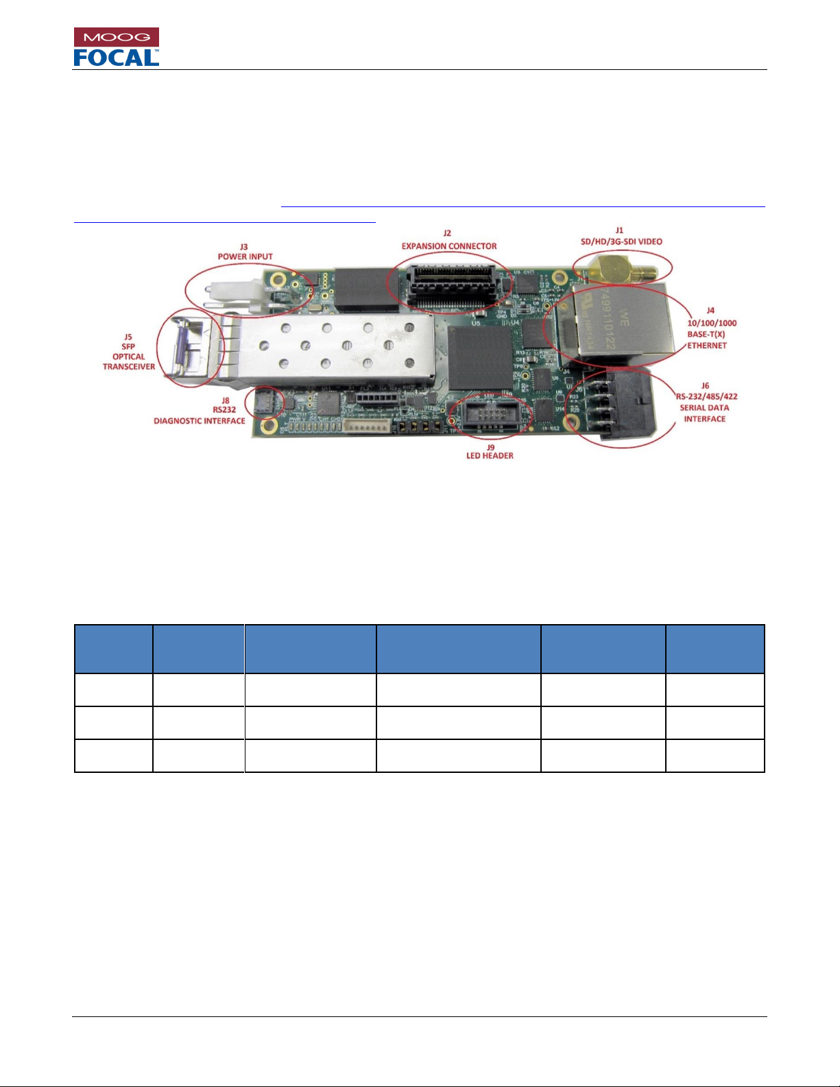
Figure 4-1 shows the top view of a 914-HDE card with user interface connectors highlighted. The remote and
console 914 cards are physically identical; the only difference between them is the EEPROM configuration and
optical transceiver. The 914-HDE does not use physical DIP switches for system configuration and settings. All
settings are accessed via the Model 914 Diagnostic GUI and are saved in non-volatile memory. Firmware updates
may also be available. Please visit http://www.moog.com/products/multiplexers-media-converters/focal-multiplexer-
product-line/multiplexer-technical-documents.html to check for updated firmware and/or manuals.
Figure 4-1: 914-HDE Top View
4.1 914-HDE Versions
Depending on system requirements, different 914-HDE versions may be ordered. Each version supports different
optical bandwidths and expansion cards. Version upgrades are possible, please contact Moog Focal for availability.
For more information regarding the expansion cards, system bandwidth capabilities, and system configurations,
please consult sections 6.0 and 3.3.
Table 4-1: 914-HDE Versions
Version
Available
Bandwidth
Serial Channels
Ethernet
Video
Supported
Expansion
Channels
L1
1.8 Gb/s
2x
RS-232/485/422
1x
10/100/1000 Mb/s *
1x
HD/SD-SDI
4x LS
M1
3.5 Gb/s
2x
RS-232/485/422
1x
10/100/1000 Mb/s **
1x
3G/HD/SD-SDI
4x LS
4x MS***
H1
5.6 Gb/s
2x
RS-232/485/422
1x
10/100/1000 Mb/s
1x
3G/HD/SD-SDI
4x LS
4x MS***
* 1000 BASE-T is not supported by default. If HD-SDI video is not required, this feature can be traded for 1000
BASE-T in L1 versions via the diagnostic GUI under the Ethernet options tab.
** In M1 version both 3G-SDI and full bandwidth gigabit Ethernet cannot be supported simultaneously. While 3GSDI video is passing through the system, the maximum available bandwidth for Ethernet is 350Mb/s.
*** MS expansion channels have limited available bandwidth, especially when 3G-SDI is active.
Page 24
Model 914-X Series Modular Multiplexer System User Manual
Focal Technologies Corporation Page 4-2
A Moog Inc. Company Document Number: 914-0601-00 Rev. 5.0
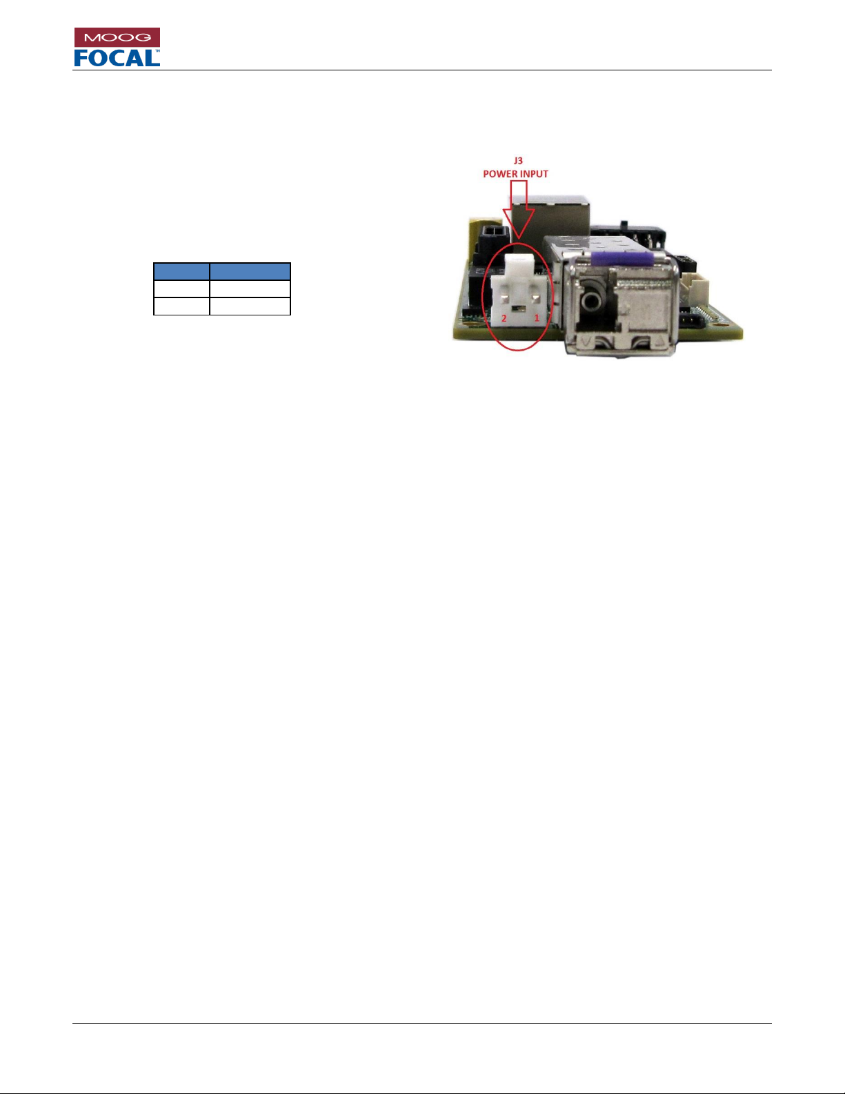
4.2 914-HDE Power
Power to the 914-HDE card is provided through connector J3, Molex P/N 09-75-2024. The mating plug is Molex
P/N 26-03-4020 with crimps P/N 08-52-0113. The pinout is provided in the table and figure below.
Figure 4-2: Power Input Connector Location
The recommended input voltage range is 4.5 VDC to 13.0 VDC (typically +5 VDC regulated). Nominal power
consumption is 5 W, increasing to 5.5 W at 60o C ambient temperature. This power consumption does not include
expansion card power requirements. Power leads should be AWG 18 – 20. Refer to section 10.5 for more details
on the system electrical and environmental specifications.
The onboard surface mount fuse, F1, is rated to 2A and is not intended to be field replaceable. If the power fuse
is blown, the card should be evaluated for damage by the factory or trained service personnel prior to any repair.
Pin #
Function
1
GND
2
VCC
Table 4-2: Power
Connector Pinout
Page 25

Model 914-X Series Modular Multiplexer System User Manual
Focal Technologies Corporation Page 4-3
A Moog Inc. Company Document Number: 914-0601-00 Rev. 5.0
4.3 914-HDE HD Video Channel
The 914-HDE card has one video port, supporting 3G/HD/SD-SDI video conforming to SMPTE 259M-C, SMPTE
292M, and SMPTE 424M-A/B. On the remote card the video is an input, and on the console it is an output.
The connector is a Mini SMB jack, Amphenol P/N 142146-75. Recommended mating plug is Cinch P/N 131-8403101, although other 75 Mini SMB plugs may be suitable. Cabling should be RG-179, 75 coaxial type. Video
latency through the mux/demux system is less than 50 s, not including fiber delays of 5 ns/m.
Figure 4-3: Mini SMB Jack - Amphenol P/N 142146-75
Figure 4-4: Video Channel 1 Connector Location
Page 26
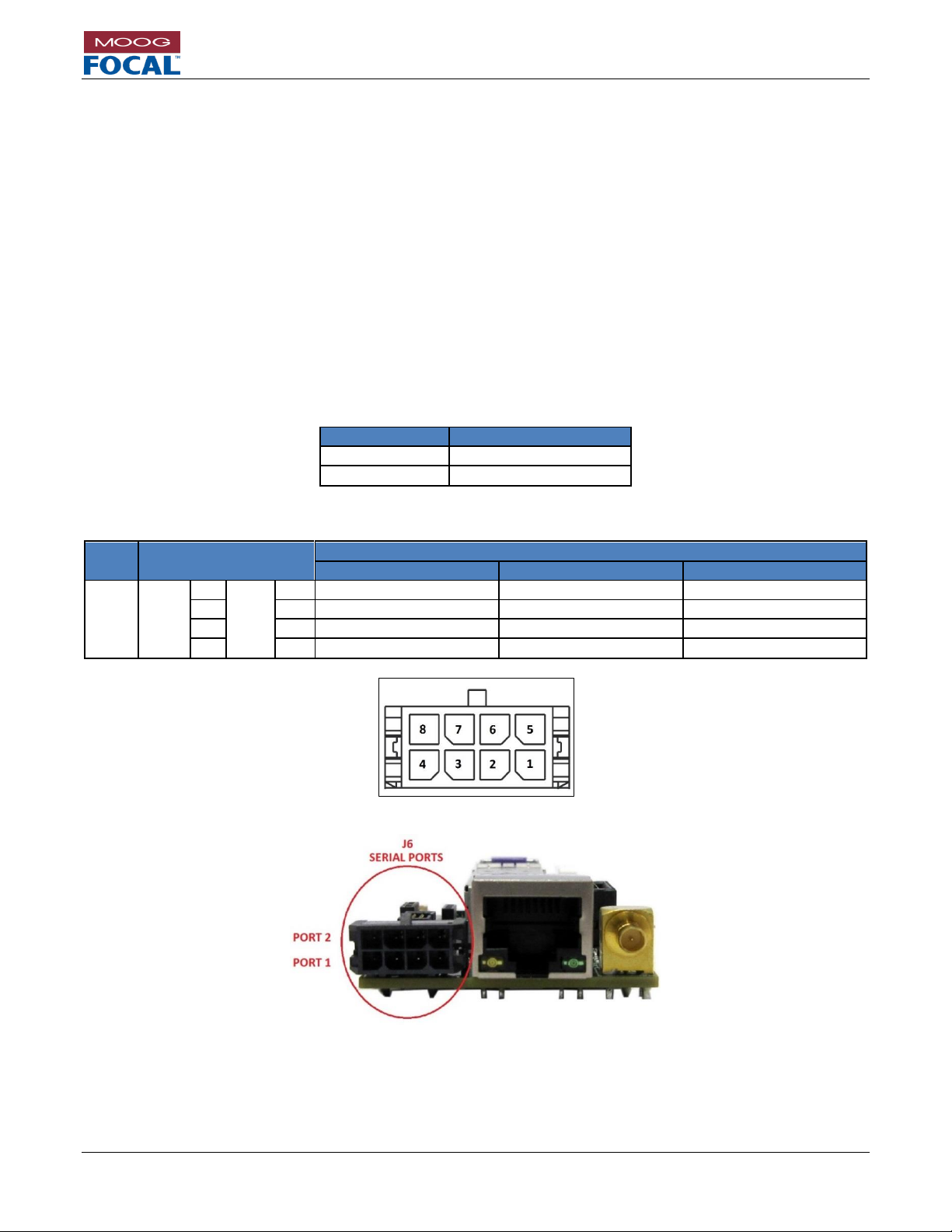
Model 914-X Series Modular Multiplexer System User Manual
Focal Technologies Corporation Page 4-4
A Moog Inc. Company Document Number: 914-0601-00 Rev. 5.0
4.4 914-HDE Serial Data Ports
The 914-HDE has two non-isolated serial ports supporting RS-232, RS-485 or RS-422 signaling protocols. These
three protocols may be configured by the user in the field via the 914 Diagnostic GUI. TTL and PPS are factory
options. All data rates are supported up to 2.5 Mbaud for RS-485 and RS-422 and up to 500 KBaud for RS-232.
Each port can support completely independent serial data links with independent baud rates. By default, RS-485
and RS-422 inputs are terminated differentially with an on-board 120 resistor that can be disabled via software
configuration. Latency through the Mux/Demux system is less than 50 s, not including fiber delays of 5 ns/m.
For RS-485 which is a half-duplex protocol, a programmable turn-around time is implemented. The default turnaround time (timeout between Tx and Rx) is set to 1 ms. Serial port settings, including protocol, timeouts, and
terminations may be accessed and changed via the Model 914 Diagnostic GUI.
The serial port connector is Molex Micro-fit P/N 43045-0800. The mating plug is Molex Micro-fit P/N 0430250800
with Molex crimps P/N 0430300010. The pinout is detailed in Table 4-4. Tx refers to transmit data from the 914HDE to the external equipment. Rx refers to receive data into the 914-HDE from the external equipment. Data
coming into the RS-422 RX lines at the remote, for example, will exit from the RS-422 TX lines at the console.
Table 4-3: Serial Data Port Numbering
Port Number
Reference Designator
1
J6 (lower pin row)
2
J6 (upper pin row)
Table 4-4: Serial Data Connector Pinout
REF.
PIN
MODE
RS-232
RS-485
RS-422
J6
CH1
1
CH2
5
RS232-RX
DO NOT CONNECT
RX 422+
2 6 GND
GND
RX 422-
3 7 DO NOT CONNECT
RS485+
TX 422+
4 8 RS232-TX
RS485-
TX 422-
Figure 4-5: Molex Micro-fit P/N 43045-0800
Figure 4-6: Serial Ports 1 and 2
Page 27
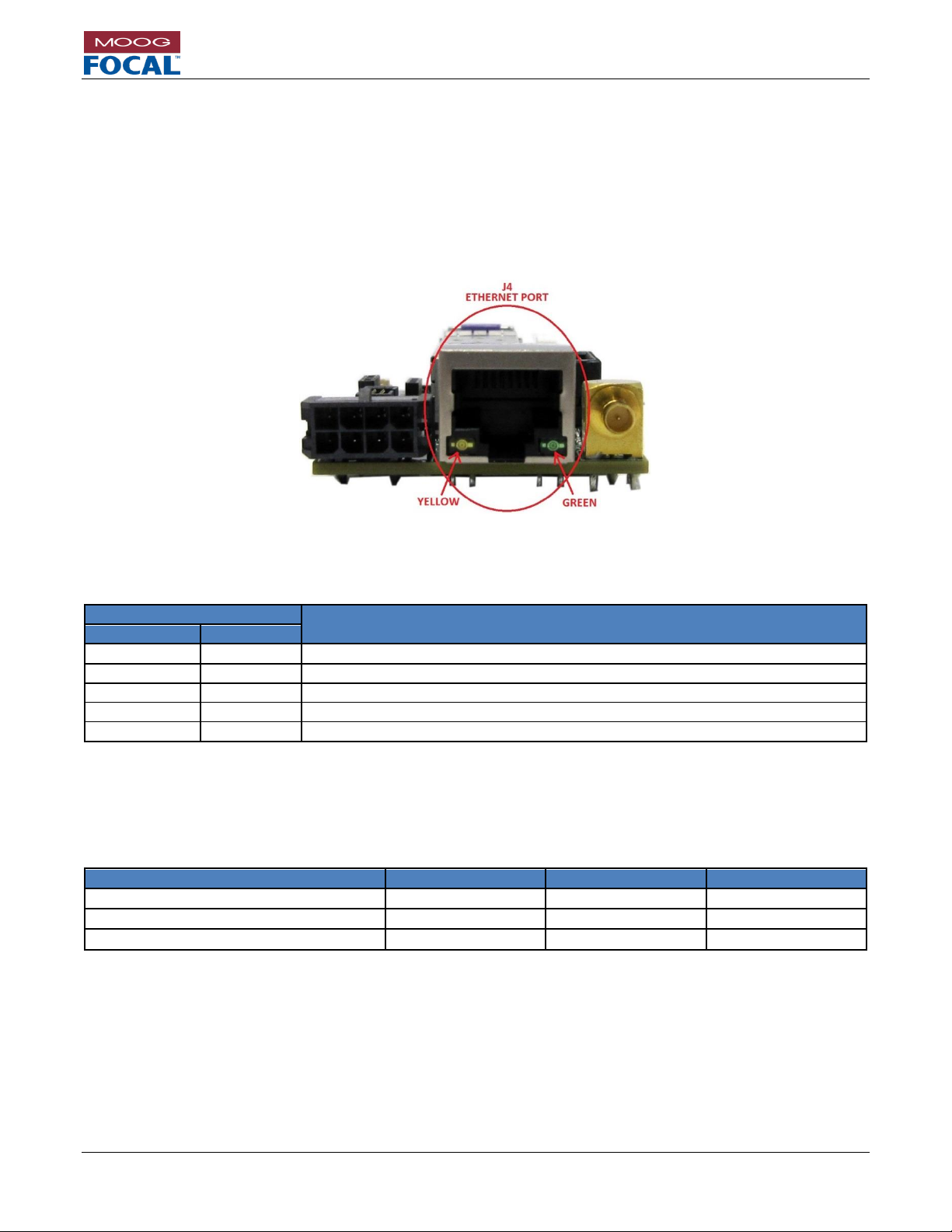
Model 914-X Series Modular Multiplexer System User Manual
Focal Technologies Corporation Page 4-5
A Moog Inc. Company Document Number: 914-0601-00 Rev. 5.0
4.5 914-HDE Ethernet Port
The 914-HDE provides an un-switched, low latency 10/100/1000 BASE-T(X) Ethernet link through the optical port.
The part is default configured for 10/100 BASE-T(X) in the L1 version, and 10/100/1000 BASE-T(X) for M1 and H1
versions. Auto-negotiate settings can be accessed via the Model 914 Diagnostic GUI. A standard 8P8C (RJ45)
modular jack provides the mechanical interface for the Ethernet port. The port is auto MDI/MDIX capable, and
supports jumbo frames up to 9000 bytes.
An optional “Link Fault Pass Through” can be enabled. This feature will disconnect the Ethernet link if the far side
is not linked. Therefore the system must be linked on both sides for the Ethernet link to be established. Enabling or
disabling this feature is done through the diagnostic GUI.
Figure 4-7: Ethernet Port
Integrated LEDs show Ethernet Link Status as shown in Table 4-5.
Table 4-5: Ethernet LEDs
LED Status
Function
Green
Yellow
OFF
OFF
No Link
ON
OFF
Linked at either 1000 BASE-T or 10 BASE-T
ON
ON
Linked at 100 BASE-TX
FLASHING
OFF
Link Activity at either 1000 BASE-T or 10 BASE-T
FLASHING
ON
Link Activity at 100 BASE-TX
End-to-end latency through the multiplexer is a calculation adding a fixed electronic latency to the Ethernet frame
time which is a function of the frame length, and the optical latency which is a function of distance. Adding all three
together gives a total latency figure.
Table 4-6: Ethernet Latency
Latency Component / Link Speed
10 Mb/s
100 Mb/s
1000 Mb/s
FEL (Fixed Electronic Latency)
30 s
6 s
3 s
FT (Frame Time)
# Bytes * 0.8 s
# Bytes * 0.08 s
# Bytes * 0.008 s
OL (Optical Latency)
5 s / km
5 s / km
5 s / km
Latency = FEL + FT + OL
Page 28
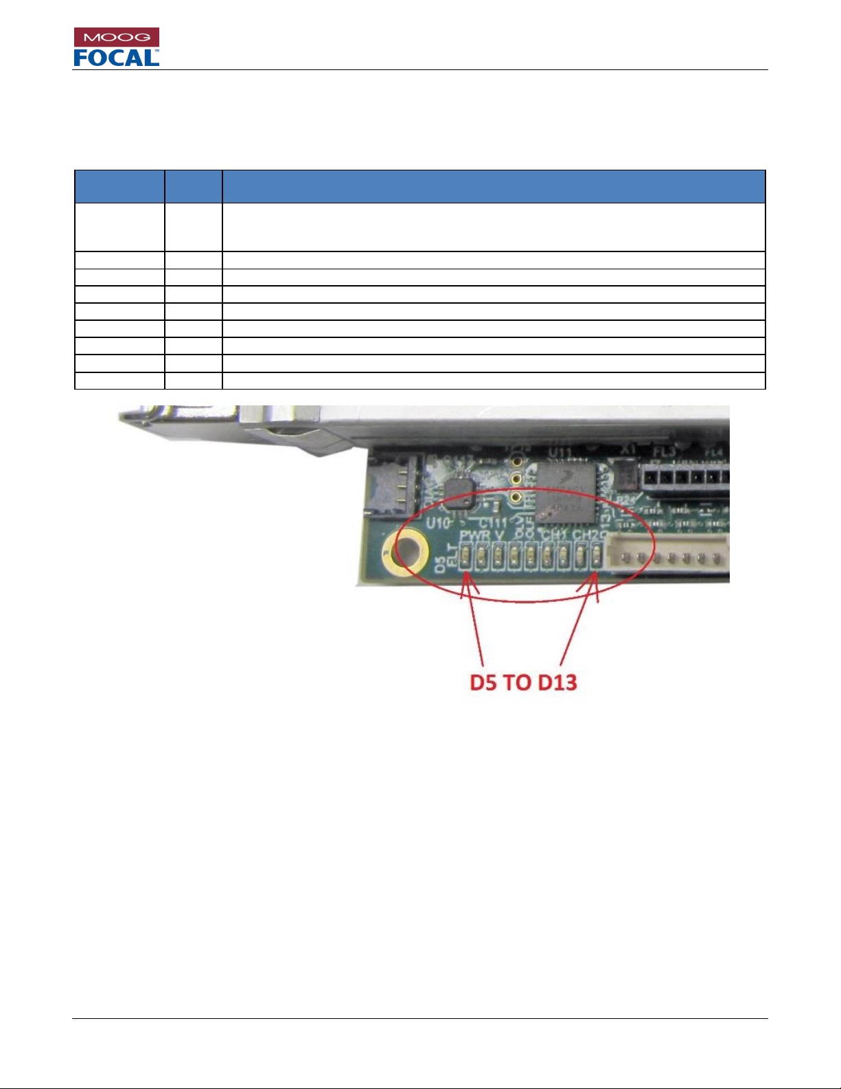
Model 914-X Series Modular Multiplexer System User Manual
Focal Technologies Corporation Page 4-6
A Moog Inc. Company Document Number: 914-0601-00 Rev. 5.0
4.6 914-HDE Diagnostic LEDs
The 914-HDE card includes 9 on-board diagnostic LEDs. A description and location of each LED is provided in
Table 4-7 and Figure 4-8.
Table 4-7: 914-HDE Diagnostic LEDs
Reference
Designator
Color
Description
D5
Red
Indicates a power fault when lit. A power fault is encountered when the input voltage
falls outside of the supported range of 4.5 to 13.5 V. Recommended input voltage is
5 VDC. When this LED is lit, the card is not powered properly and will not function.
D6
Green
Indicates that the card is powered properly when lit.
D7
Green
Indicates a valid video signal is present when lit
D8
Green
Indicates a valid optical link is being received. (data frames are present)
D9
Red
Indicates that insufficient optical power is present at the receiver.
D10
Green
Flashing LED indicates serial channel 1 is transmitting to external equipment.
D11
Yellow
Flashing LED indicates serial channel 1 is receiving from external equipment.
D12
Green
Flashing LED indicates serial channel 2 is transmitting to external equipment.
D13
Yellow
Flashing LED indicates serial channel 2 is receiving from external equipment.
Figure 4-8: Diagnostic LEDs
Page 29
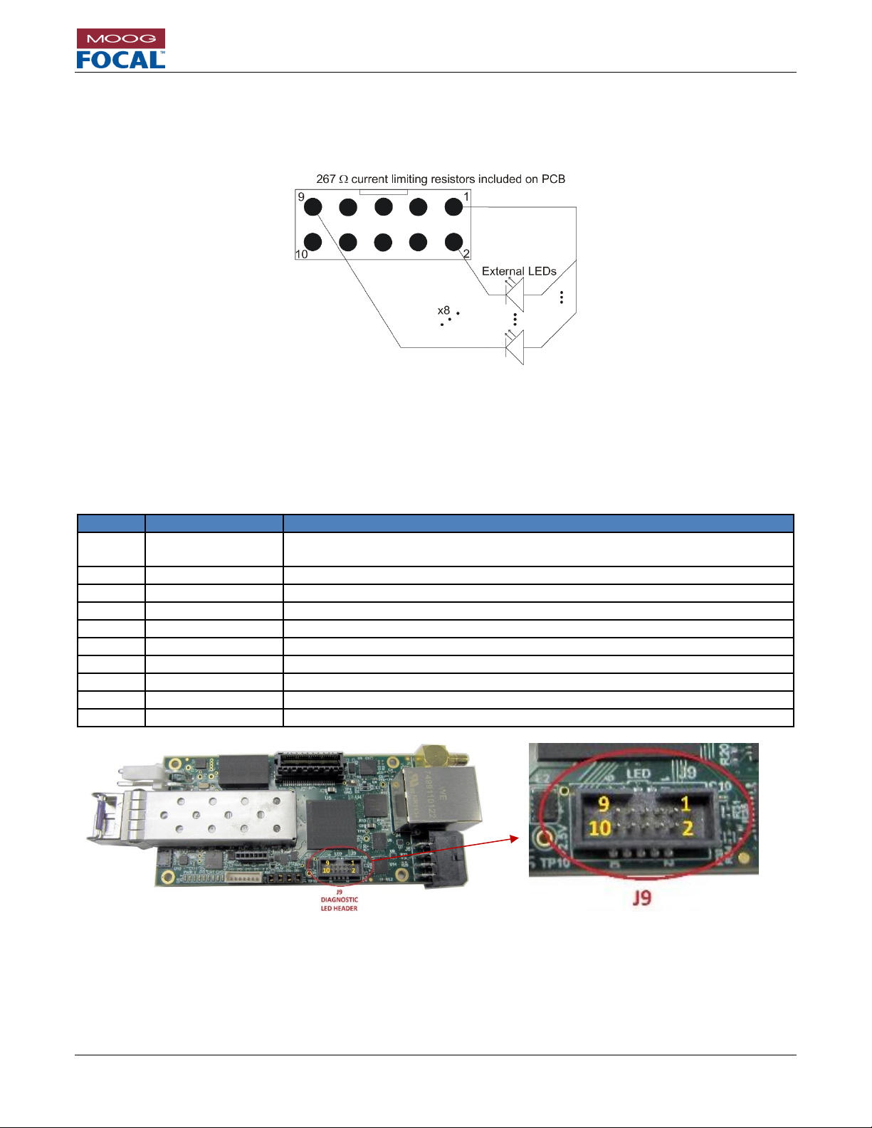
Model 914-X Series Modular Multiplexer System User Manual
Focal Technologies Corporation Page 4-7
A Moog Inc. Company Document Number: 914-0601-00 Rev. 5.0
4.7 914-HDE Diagnostic LED Header
The 914-HDE card includes a 10-pin header capable of driving 8 LEDs. This is useful for LED integration into an
enclosure. Each LED pin is driven low to turn on an LED, and includes a 267 ohm resistor in series to limit the
current draw. Maximum current draw per LED pin is 8 mA.
Figure 4-9: External LED Circuit Diagram
This header may optionally become an input via the diagnostic GUI with firmware revisions greater than B1.
The LED header J9 is FCI P/N 20021521-00010T1LF, and the mating part is FCI P/N 20021444-00010T1LF. This
can be used with most 0.050” (1.27mm) spacing ribbon cables.
Table 4-8: 914-HDE Diagnostic LED Header Pinout
Pin
Name
Description
1
3.3V
3.3V
This pin can be used to drive the LEDs, Maximum current is 0.5A.
2
LINK
Indicates a valid optical link is being received. Active low.
3
LINK FAULT
Indicates that insufficient optical power is present. Active low.
4
VIDEO
Indicates a valid video signal is present when lit. Active low.
5
ETHERNET
Indicates that an Ethernet link is established locally. Active low.
6
SER1 RX
Flashing LED indicates serial channel 1 receive activity. Active low.
7
SER1 TX
Flashing LED indicates serial channel 1 transmit activity. Active low.
8
SER2 RX
Flashing LED indicates serial channel 2 receive activity. Active low.
9
SER2 TX
Flashing LED indicates serial channel 2 transmit activity. Active low.
10
GND
Ground
Figure 4-10: Diagnostic LED Header
Page 30
Model 914-X Series Modular Multiplexer System User Manual
Focal Technologies Corporation Page 4-8
A Moog Inc. Company Document Number: 914-0601-00 Rev. 5.0
4.8 914-HDE Optics
An SFP or SFP+ transceiver provides the optical interface for the 914-HDE. Many options exist including:
Singlemode or multimode fiber
Bi-directional 1310/1550 nm transceivers (L1 and M1 versions)
Bi-directional 1270/1330 nm transceivers (H1 version)
CWDM wavelengths (L1, M1 or H1 versions)
Non-standard optical budgets
Due to the high data rates, singlemode fiber is standard. Multimode fiber is only suitable for very short links (<
300m). Contact Moog Focal for multimode options. Typical link budgets for single mode fiber are 20dB for bidirectional single fiber or 24dB for dual fiber CWDM. Moog Focal has compatible CWDM modules that can be
mounted and stacked with 914-HDE systems. Please refer to section 8.0.
4.8.1 914-HDE Flux Budget Calculation
When specifying an optical system, it is important to analyze system losses and fiber link distances in order to
calculate the required optical configuration. The following table shows a sample flux budget calculation for a system
with multiple ST bushings, a 10 km singlemode fiber link and a FORJ. Actual losses can vary widely from this, each
system flux budget calculation must use data based on actual parts in use.
Table 4-9: Sample Flux Budget Calculation
Component
Uplink (1310 nm)
Downlink (1550 nm)
Unit
Typical Output Power
-1.0
-1.0
dBm
Connector
0.3
0.3
dB
Connector
0.3
0.3
dB
Fiber Optic Rotary Joint
4.0
4.0
dB
Connector
0.3
0.3
dB
Connector
0.3
0.3
dB
Cable (for 10 km SMF length)
4.0
3.0
dB
Connector
0.3
0.3
dB
Connector
0.3
0.3
dB
Total Losses
9.8
8.8
dB
Received Power
-10.8 (=-1.0 dBm - 9.8 dB)
-9.8 (=-1.0 dBm - 8.8 dB)
dBm
Dispersion Penalty
1.0
1.0
dB
Required Receive Sensitivity
-11.8
-10.8
dBm
Typical Receive Sensitivity
-21.0
-21.0
dBm
Available Margin
9.2
10.2
dB
Assumptions:
Fiber Loss 0.4 dB/km @ 1310 nm; 0.3 dB/km @1550 nm (single mode fiber - SMF).
Connector (ST/PC) 0.3 dB/conn
FORJ Loss (Max.) 4.0 dB
4.8.2 Optical Safety
All lasers used in the 914-HDE system are Class I laser devices per IEC-60825 unless otherwise specified in
installation or configuration drawing. No special control measures or warning labels are required, although any
needless exposure of the eye should be avoided as a matter of good practice, and fibers should never be viewed
with magnifying instruments, e.g. fiber scopes, while optical power is present. Note that the optical
wavelengths are in the infrared range, so not visible, but magnifying instruments can still cause damaging levels to
the eye.
Page 31

Model 914-X Series Modular Multiplexer System User Manual
Focal Technologies Corporation Page 5-1
A Moog Inc. Company Document Number: 914-0601-00 Rev. 5.0
5.0 Model 914-X Series Diagnostic GUI
The 914-X Series has advanced diagnostics available over a dedicated RS-232 port on the console 914-HDE
motherboard. This one port gives access to all* 914 cards in the 914-X Series system, including those at the
remote side if the fiber optic link is established. This diagnostic link is critical during the setup phase of any system,
as it gives access to the settings of any port in the system. This is useful to configure serial port protocols, Ethernet
negotiation settings, and any special video settings, for example. Do not connect directly to the REMOTE 914-
HDE RS232 diagnostic port for configuration purposes, as the settings will not be retained.
*914-HDV2 has its own diagnostic port
Figure 5-1 shows a typical setup between a 914 card and a PC to obtain diagnostics information from both console
and remote ends.
Figure 5-1: Basic Diagnostics Setup
The diagnostics serial port configuration is as follows:
Speed: 115200 baud
Data bits: 8
Stop bits: 1
Parity: None
Flow Control: None
Included with every 914-X Series card is a pigtailed jumper for the RS-232 diagnostic port, as shown in the figure
below. This cable plugs into J8 on the console 914-HDE PCBA. To install the cable, the plug is pressed down into
the connector and should be epoxied in place for permanent connection. Extra cables provide firmware update
access for individual cards.
Figure 5-2: 914-HDE Diagnostic Interface Cable
DIAGNOSTICS
PC WITH
RS-232 PORT
+VIN
GND 1
2
1
SERIAL
DIAGNOSTICS
CABLE
+VIN
GND 1
2
1
CONSOLE (SURFACE)
CARD
REMOTE (SUBSEA)
CARD
FIBER OPTIC CABLE SYSTEM
Page 32
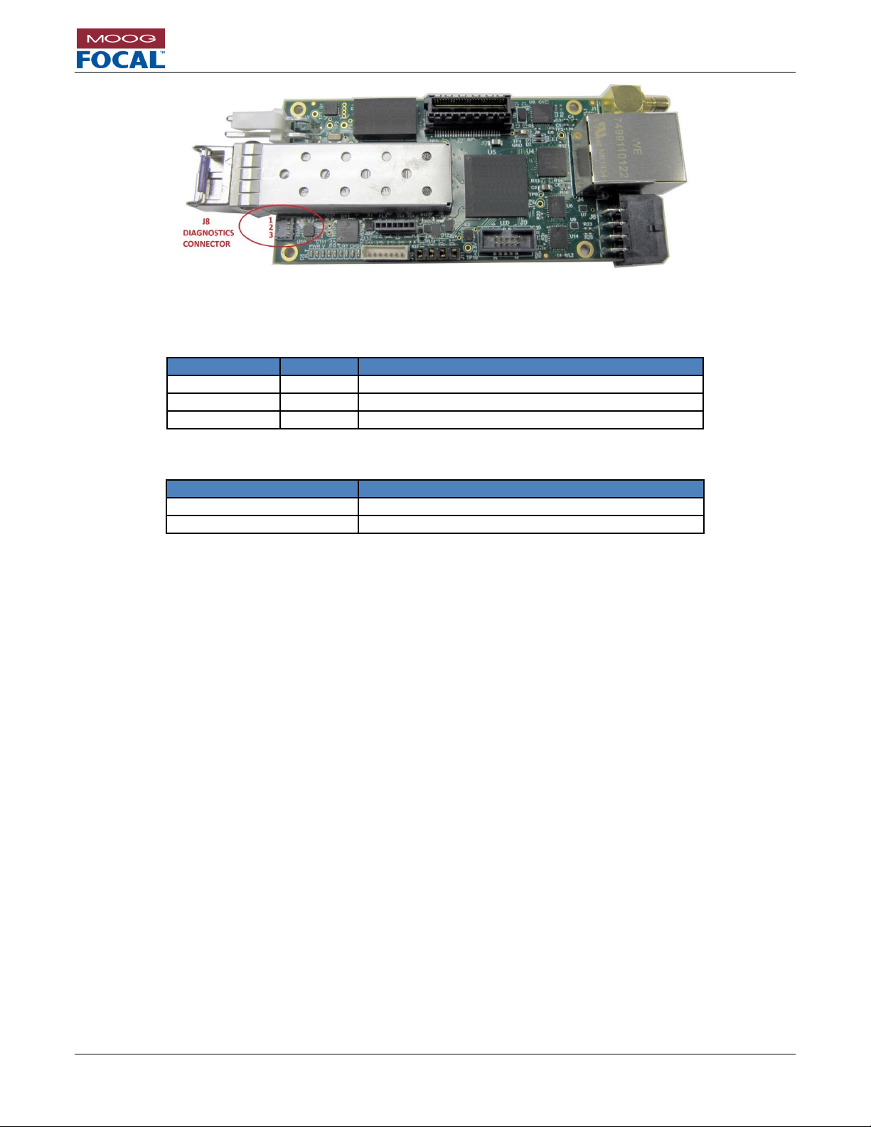
Model 914-X Series Modular Multiplexer System User Manual
Focal Technologies Corporation Page 5-2
A Moog Inc. Company Document Number: 914-0601-00 Rev. 5.0
Figure 5-3: 914-HDE Diagnostic Connector
Table 5-1: J8 Diagnostic Connector Pinout
Pin Number
Colour
Function
1
Black
GND
2
Violet
RS-232 Tx (Data from 914-HDE to PC GUI)
3
White
RS-232 Rx (Data from PC GUI)
Table 5-2: Diagnostic Connector Part Numbers
J8
Part Number
Connector
Molex 0781710003
Mating Plug
Molex 0781720003
Page 33
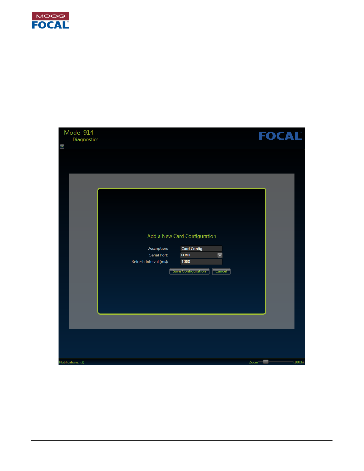
Model 914-X Series Modular Multiplexer System User Manual
Focal Technologies Corporation Page 5-3
A Moog Inc. Company Document Number: 914-0601-00 Rev. 5.0
5.1 Installing the Model 914-X Series Diagnostic GUI
Check for the latest software release on the Moog Focal website: http://www.moog.com/focal/914-x-series and
search for 914-0401-00.
Install the software on a computer with Microsoft Windows 7 (or newer Microsoft OS) and a serial (COM) port
connected to the 914-HDE diagnostic port. Microsoft .NET version 4.0 or greater must be installed on the host
computer. Installation of the Model 914 diagnostic GUI will involve copying the compressed software package to a
local drive, then uncompressing to “C:\Focal\”. Follow the instructions in the “Installation.txt” file and open the
"Model914.exe" file. Once installed, open the software and press the (+) at the top left corner to set up the COM
link.
The following section is an overview of the diagnostic GUI.
Figure 5-4: Diagnostic GUI Start Screen
Once the COM port is setup, press “Start Data Refresh” at the bottom of the screen.
If a successful link to the 914-HDE is established, a green heart will be seen at the top left of the screen near the
COM port listing. If the heart appears red, the link has not been established. Verify the COM port number and the
wiring harness to the PCBA and ensure power is applied to the 914-HDE.
Page 34
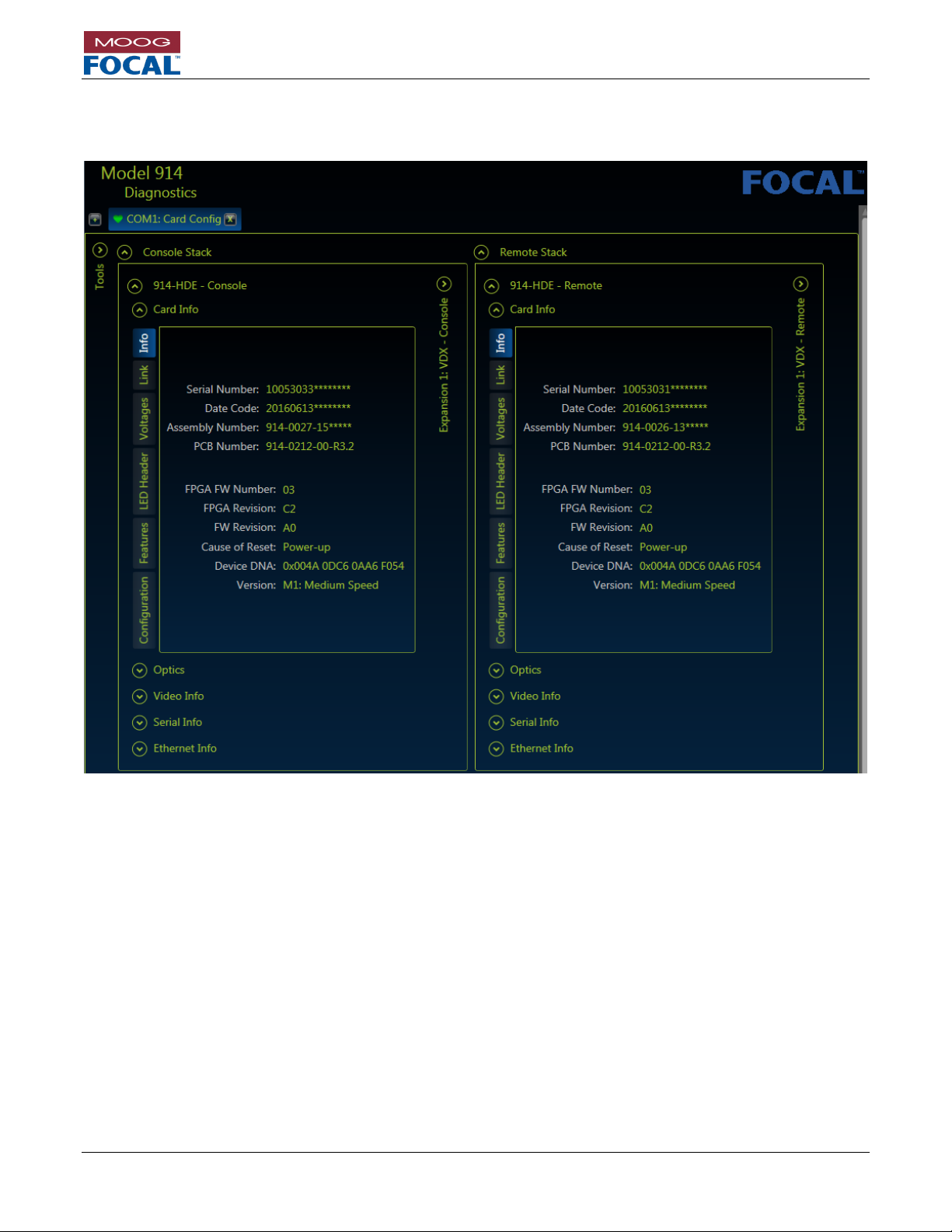
Model 914-X Series Modular Multiplexer System User Manual
Focal Technologies Corporation Page 5-4
A Moog Inc. Company Document Number: 914-0601-00 Rev. 5.0
When the link is established, click on the “Model 914 – Console” and “Model 914 Remote” text to pull up a list of
card features, including the card info as displayed in Figure 5-5.
Figure 5-5: 914-HDE Card Info
Page 35

Model 914-X Series Modular Multiplexer System User Manual
Focal Technologies Corporation Page 5-5
A Moog Inc. Company Document Number: 914-0601-00 Rev. 5.0
5.1.1 914-HDE Diagnostic Status Display
Navigating through the drop down tabs and expansion buttons allows more system information to be extracted.
Figure 5-6 shows all the system voltages as well as the FPGA junction temperature. A green background indicates
that the observed status is within the normal range. Red backgrounds indicate potential problems that need to be
addressed. Yellow backgrounds give warnings.
Figure 5-6: 914-HDE Voltage and Junction Temperature Information
Page 36
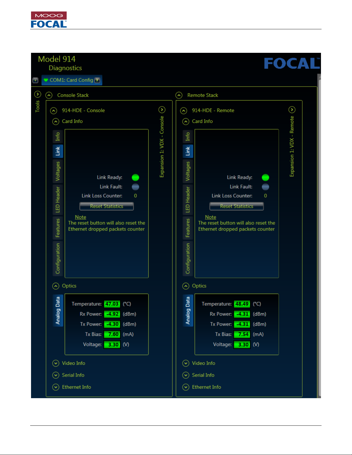
Model 914-X Series Modular Multiplexer System User Manual
Focal Technologies Corporation Page 5-6
A Moog Inc. Company Document Number: 914-0601-00 Rev. 5.0
Figure 5-7 shows the optical link status, including information provided by the optical transceiver, such as transmit
and receive optical power and transceiver temperature.
Figure 5-7: 914-HDE Optical Link Status
Page 37
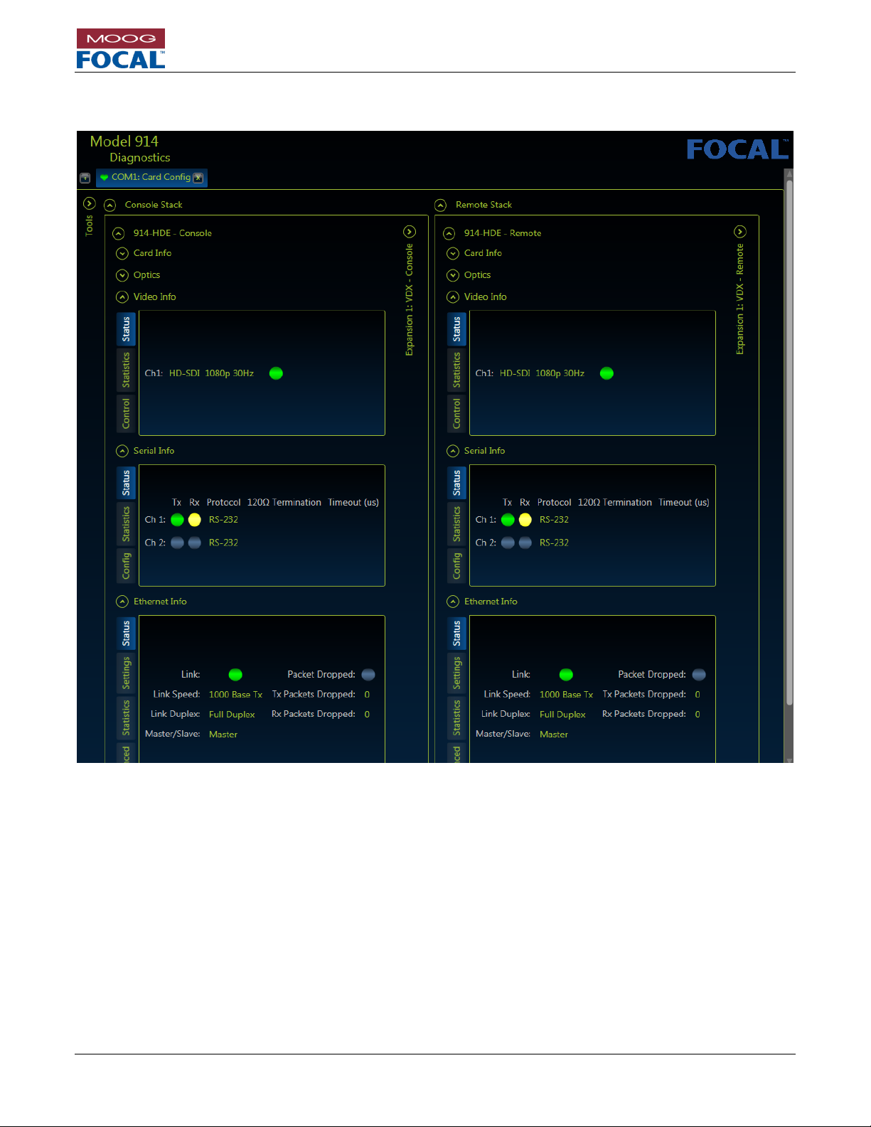
Model 914-X Series Modular Multiplexer System User Manual
Focal Technologies Corporation Page 5-7
A Moog Inc. Company Document Number: 914-0601-00 Rev. 5.0
Figure 5-8 shows the current status of each input / output signal (video, serial and Ethernet). Receive serial activity
is shown in yellow to match the LEDs on the 914-HDE.
Figure 5-8: 914-HDE Signal Status
Page 38

Model 914-X Series Modular Multiplexer System User Manual
Focal Technologies Corporation Page 5-8
A Moog Inc. Company Document Number: 914-0601-00 Rev. 5.0
5.1.2 914-HDE Serial Port Configuration
Figure 5-9 shows how to configure each serial port. Select the desired protocol, termination and timeout (if
applicable). Press “Apply” to save the changes. These settings are non-volatile and do not need to be re-configured
each time the 914-HDE is powered.
Typical Settings: (Refer to Section 4.4)
RS-485: 1 ms timeout; terminations enabled
RS-422: terminations enabled
RS-232: No options.
Figure 5-9: 914-HDE Serial Port Configuration
Page 39

Model 914-X Series Modular Multiplexer System User Manual
Focal Technologies Corporation Page 5-9
A Moog Inc. Company Document Number: 914-0601-00 Rev. 5.0
5.1.3 914-HDE Ethernet Port Configuration
Figure 5-10 shows how to configure the Ethernet port auto-negotiation settings. By default the system will autonegotiate to the highest possible speed, but these settings are useful to ensure both side negotiate to the same
speed and duplex if they did not automatically do this.
Ethernet link speed mismatches should be avoided. Typically newer PCs will link at 1G at the console side and
older Ethernet equipment at the remote side might link at 100M. In this case, the console and remote cards should
be set to 100M and the PC should be forced to 100M to ensure that all elements in the Ethernet link are set at the
same speed.
Figure 5-10: 914-HDE Ethernet Settings
Page 40
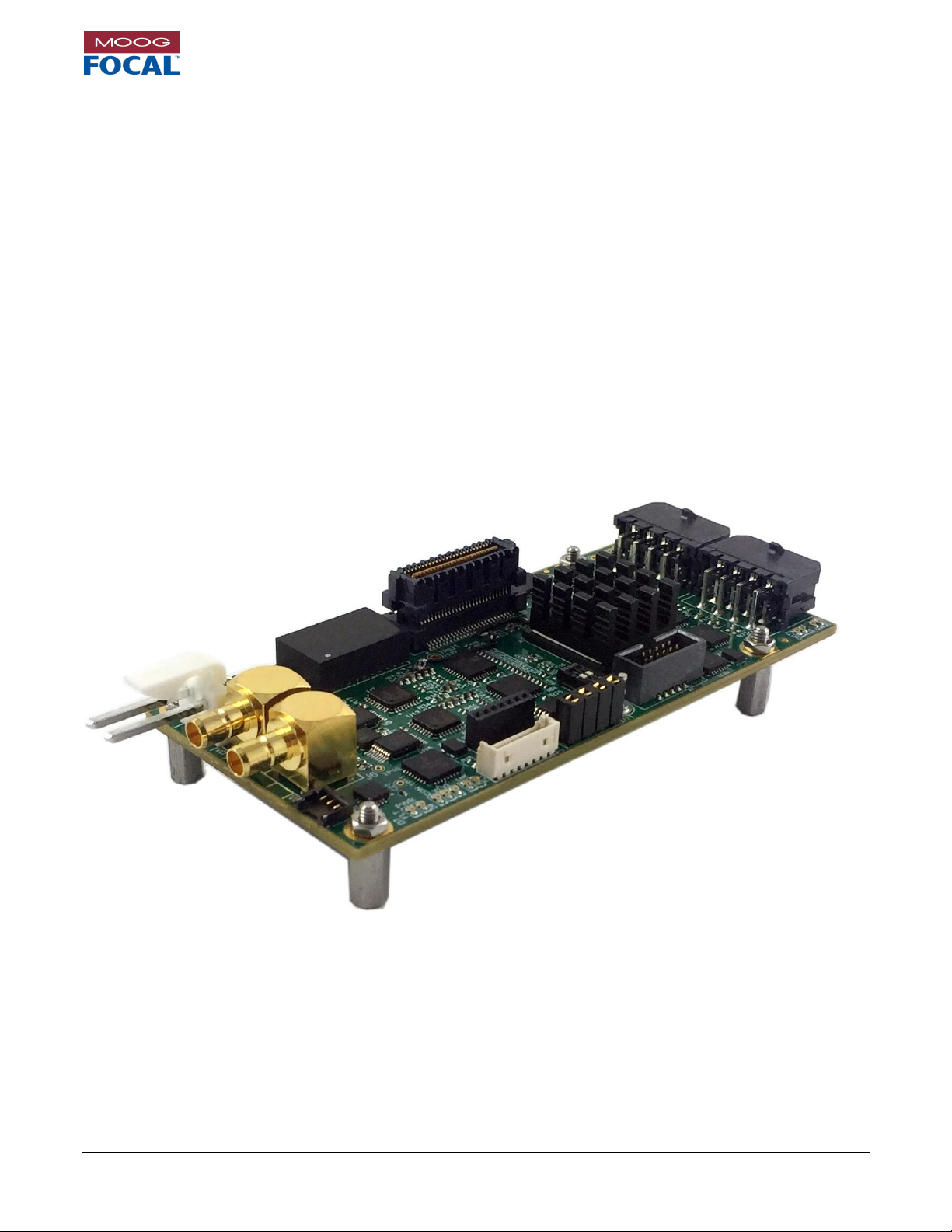
Model 914-X Series Modular Multiplexer System User Manual
Focal Technologies Corporation Page 6-1
A Moog Inc. Company Document Number: 914-0601-00 Rev. 5.0
6.0 914-X Series Expansion Cards
The 914-HDE motherboard is a full multiplexing system capable of supporting up to 8 expansion cards
simultaneously through a multi-gigabit board-to-board expansion connector. A separate backplane card is not
required. Moog Focal has developed a family of compatible expansion cards that allow the user to specify more
signals without adding more fibers. This reduces cost and size as compared to adding media converters or
additional multiplexer cards. The expansion connector has 4 medium speed channels and 4 low speed channels
available.
The expansion connector provides for 21/32” (16.67 mm) spacing between cards when directly stacked together.
For tight spaces and/or larger stacks, Moog Focal can provide high speed ribbon cables to allow cards to sit up to
18” (46 cm) apart. Please refer to Section 10.3 for more information.
6.1 914-VDX
The 914-VDX (video and serial data expansion card) provides 2 channels of analog (composite) video and 4
channels of non-isolated serial data (RS-232, RS-485, RS-422). The video channels are compatible with both NTSC
and PAL standards. Diagnostics from this card are provided to the 914-HDE and are available to the Model 914-X
Series Diagnostic GUI. This expansion card requires up to 550 Mb/s of bandwidth from the 914-HDE motherboard.
This expansion card requires 1 medium speed expansion channel.
Figure 6-1: 914-VDX
Page 41

Model 914-X Series Modular Multiplexer System User Manual
Focal Technologies Corporation Page 6-2
A Moog Inc. Company Document Number: 914-0601-00 Rev. 5.0
6.1.1 914-VDX Serial Data Ports
The 914-VDX has four non-isolated serial ports supporting RS-232, RS-485 or RS-422 signaling protocols. These
three protocols may be configured by the user in the field via the 914 Diagnostic GUI. TTL and PPS are factory
options. All data rates are supported up to 1.25 Mbaud for RS-485 and RS-422 and up to 500 KBaud for RS-232.
Each port can support completely independent serial data links with independent baud rates. By default, RS-485
and RS-422 inputs are terminated differentially with an on-board 120 resistor that can be disabled via software
configuration. Latency through the Mux/Demux system is less than 500 s, not including fiber delays of 5 ns/m.
For RS-485 which is a half-duplex protocol, a programmable turn-around time is implemented. The default turnaround time (timeout between Tx and Rx) is set to 1 ms. Serial port settings, including protocol, timeouts, and
terminations may be accessed and changed via the Model 914 Diagnostic GUI.
The serial port connector is Molex Micro-fit P/N 43045-0800. The mating plug is Molex Micro-fit P/N 0430250800
with Molex crimps P/N 0430300010. The pinout is detailed in Table 6-2. Tx refers to transmit data from the 914VDX to the external equipment. Rx refers to receive data into the 914-VDX from the external equipment. Data
coming into the RS-422 RX lines at the remote, for example, will exit from the RS-422 TX lines at the console.
Table 6-1: Serial Data Port Numbering
Port Number
Reference Designator
1
J5 (lower pin row)
2
J5 (upper pin row)
3
J3 (lower pin row)
4
J3 (upper pin row)
Table 6-2: Serial Data Connector Pinout
REF.
PIN
MODE
RS-232
RS-485
RS-422
J6
CH1
1
CH2
5
RS232-RX
DO NOT CONNECT
RX 422+
2 6 GND
GND
RX 422-
3 7 DO NOT CONNECT
RS485+
TX 422+
4 8 RS232-TX
RS485-
TX 422-
Figure 6-2: Molex Micro-fit
P/N 43045-0800
Figure 6-3: VDX Serial Ports
Page 42

Model 914-X Series Modular Multiplexer System User Manual
Focal Technologies Corporation Page 6-1
A Moog Inc. Company Document Number: 914-0601-00 Rev. 5.0
6.1.2 914-VDX Composite Video Channels
The 914-VDX has two NTSC or PAL compatible composite video channels. The channel direction (input vs output)
is set up from the Model 914 Diagnostic GUI. Each channel uses approximately 250 Mb/s of available bandwidth
from the 914-HDE. No bandwidth is used if the video input is unplugged, or if that channel has been disabled via
the Diagnostic GUI. Latency through the Mux/Demux system is less than 500 s, not including fiber delays of 5
ns/m.
Coaxial shielding on the connectors is directly tied to ground, care must be taken to ensure a common ground to
all video equipment or isolation must be installed external to the 914-VDX. The video signal is AC coupled on the
PCBA.
The connector is a Mini SMB jack, Amphenol P/N 142146-75. Recommended mating plug is Cinch P/N 131-8403101, although other 75 Mini SMB plugs may be suitable. Cabling should be RG-179, 75 coaxial type. Video
latency through the mux/demux system is less than 25 s, not including fiber delays of 5 ns/m.
Figure 6-4: Mini SMB Jack - Amphenol P/N 142146-75
Figure 6-5: Video Connector Locations
Page 43

Model 914-X Series Modular Multiplexer System User Manual
Focal Technologies Corporation Page 6-2
A Moog Inc. Company Document Number: 914-0601-00 Rev. 5.0
6.1.3 914-VDX Power
Power to the 914-VDX card is provided via the expansion connector. Power input connect J3 should not be used
during normal operation with the 914-VDX. It can optionally be used for standalone operation during firmware
updates or configuration.
If the 914-VDX is to be self-powered, this is accomplished via connector J3, Molex P/N 09-75-2024. The mating
plug is Molex P/N 26-03-4020 with crimps P/N 08-52-0113. The pinout is provided in the table and figure below.
Figure 6-6: Power Input Connector Location
The recommended input voltage range is 4.5 VDC to 13.0 VDC (typically +5 VDC regulated). Nominal power
consumption is 5 W, increasing to 5.5 W at 60o C ambient temperature. Power leads should be AWG 18 – 20.
The onboard surface mount fuse, F1, is rated to 2A and is not intended to be field replaceable. If the power fuse
is blown, the card should be evaluated for damage by the factory or trained service personnel prior to any repair.
Pin #
Function
1
GND
2
VCC
Table 6-3: Power
Connector Pinout
Page 44

Model 914-X Series Modular Multiplexer System User Manual
Focal Technologies Corporation Page 6-3
A Moog Inc. Company Document Number: 914-0601-00 Rev. 5.0
6.1.4 914-VDX Diagnostic LEDs
The 914-VDX card includes 15 on-board diagnostic LEDs. A description and location of each LED is provided in
Table 4-7 and Figure 4-8.
Table 6-4: 914-VDX Diagnostic LEDs
Reference
Designator
Color
Description
D1
Green
Flashing LED indicates serial channel 3 is transmitting to external equipment.
D2
Yellow
Flashing LED indicates serial channel 3 is receiving from external equipment.
D3
Green
Flashing LED indicates serial channel 4 is transmitting to external equipment.
D4
Yellow
Flashing LED indicates serial channel 4 is receiving from external equipment.
D7
Red
Indicates a power fault when lit. A power fault is encountered when the input voltage
falls outside of the supported range of 4.5 to 13.5 V. Recommended input voltage is
5 VDC. When this LED is lit, the card is not powered properly and will not function.
D8
Green
Indicates that the card is powered properly when lit.
D9
Green
Indicates the 914-VDX is configured for Console mode.
D10
Green
Indicates a valid video signal is present on channel 1 when lit
D11
Green
Indicates a valid video signal is present on channel 2 when lit
D12
Green
Indicates a valid expansion link is being received. (data frames are present)
D13
Red
Indicates the expansion link is in fault condition. (little or no valid data is present)
D14
Green
Flashing LED indicates serial channel 1 is transmitting to external equipment.
D15
Yellow
Flashing LED indicates serial channel 1 is receiving from external equipment.
D16
Green
Flashing LED indicates serial channel 2 is transmitting to external equipment.
D17
Yellow
Flashing LED indicates serial channel 2 is receiving from external equipment.
Figure 6-7: VDX Diagnostic LEDs
Page 45

Model 914-X Series Modular Multiplexer System User Manual
Focal Technologies Corporation Page 6-4
A Moog Inc. Company Document Number: 914-0601-00 Rev. 5.0
6.1.5 914-VDX Diagnostic LED Header
The 914-VDX card includes a 10-pin header capable of driving 8 LEDs. This is useful for LED integration into an
enclosure. Each LED pin is driven low to turn on an LED, and includes a 267 ohm resistor in series to limit the
current draw. Maximum current draw is 8 mA. Refer to section 4.7 for a sample connection diagram.
Serial data activity header pins can be configured for Tx (Transmit Activity), Rx (Receive Activity), or both (Default)
via the diagnostic GUI.
The LED header is FCI P/N 20021521-00010T1LF, and the mating part is FCI P/N 20021444-00010T1LF. This can
be used with most 0.050” (1.27mm) spacing ribbon cables.
Table 6-5: 914-VDX Diagnostic LED Header Pinout
Pin
Name
Description
1
3.3V
3.3V
This pin can be used to drive the LEDs, Maximum current is 0.5A.
2
VIDEO CH1
Indicates a valid video signal is present on channel 1 when lit. Active low.
3
VIDEO CH2
Indicates a valid video signal is present on channel 2 when lit. Active low.
4
SER1 RX
Flashing LED indicates serial channel 1 activity. Active low.
5
SER1 TX
Flashing LED indicates serial channel 2 activity. Active low.
6
SER2 RX
Flashing LED indicates serial channel 3 activity. Active low.
7
SER2 TX
Flashing LED indicates serial channel 4 activity. Active low.
8
EXPANSION LINK
Indicates a valid expansion link is present. Active low.
9
EXPANSION LINK
FAULT
Indicates that the expansion link is in a fault condition. Active low.
10
GND
Ground, non-isolated, connected to 914-HDE input voltage ground.
Figure 6-8: Diagnostic LED Header
Page 46

Model 914-X Series Modular Multiplexer System User Manual
Focal Technologies Corporation Page 6-5
A Moog Inc. Company Document Number: 914-0601-00 Rev. 5.0
6.1.6 914-VDX Expansion Channel Configuration
Up to four 914-VDX cards may be stacked on each 914-HDE, depending on available optical bandwidth. Dip switch
SW1 configures which expansion channel each card uses. The card closest to the 914-HDE must be configured for
expansion channel 1, with each subsequent card configured for the next channel in succession. No channels may
be skipped.
Table 6-6: 914-VDX Expansion Channel Configuration
SW1[1:2]
Setting
OFF, OFF
Expansion channel 1
ON, OFF
Expansion channel 2
OFF, ON
Expansion channel 3
ON, ON
Expansion channel 4
Figure 6-9: Diagnostic LED Header
Figure 6-10: SW1 Position and Orientation
Page 47

Model 914-X Series Modular Multiplexer System User Manual
Focal Technologies Corporation Page 6-6
A Moog Inc. Company Document Number: 914-0601-00 Rev. 5.0
6.1.7 914-VDX Configuration
By default, all 914-VDX cards are shipped with these settings:
Remote configuration
Both video channels are inputs and enabled
All serial channels are set to RS232
To change these settings, connect the console 914-HDE to the 914 Diagnostic GUI via a local COM port. Ensure a
stable optical link is present and the cards are stacked together in the correct order with the correct expansion
settings as per the previous section.
From the GUI, click on the “Card Info” then “Configuration” tab as shown in Figure 6-11. Typically the console stack
side needs to be changed from the default remote with video inputs, to console with video outputs. Once the desired
“new” settings are selected, press apply to save them to the card.
The Driver Voltage indicates the drive strength for the expansion interface. For 914-VDX cards that are distant from
the 914-HDE (either stacked at expansion channel 2+, or are using a high speed ribbon cable) it may be necessary
to boost this from the default setting of 682 mV. This setting should never be set below 682 mV.
Figure 6-11: 914-VDX Video Configuration
Page 48

Model 914-X Series Modular Multiplexer System User Manual
Focal Technologies Corporation Page 6-7
A Moog Inc. Company Document Number: 914-0601-00 Rev. 5.0
6.1.8 914-VDX Serial Port Configuration
To alter the serial port settings from the GUI, click on the “Serial Info” then “Config” tab as shown in Figure 6-12.
Select new settings on a port by port basis and press apply. Each setting can take up to 10 seconds to save in nonvolatile memory (EEPROM).
Figure 6-12: 914-VDX Serial Port Configuration
Page 49

Model 914-X Series Modular Multiplexer System User Manual
Focal Technologies Corporation Page 6-8
A Moog Inc. Company Document Number: 914-0601-00 Rev. 5.0
6.1.9 914-VDX Diagnostics
In a similar manner to the 914-HDE, the 914-VDX has available diagnostics from the GUI including all voltages and
the junction temperature of the FPGA. Any value shown in green is operating within normal specification. Values in
red or yellow should be examined.
Figure 6-13: 914-VDX Voltages and Temperature
Page 50

Model 914-X Series Modular Multiplexer System User Manual
Focal Technologies Corporation Page 6-9
A Moog Inc. Company Document Number: 914-0601-00 Rev. 5.0
6.2 914-EX
The 914-EX (Ethernet expansion card) provides an additional two (2) 10/100/1000 BASE-T(X) ports to a 914-HDE
system. These ports are multiplexed into the 914-HDE optical data stream. This design is switchless ensuring no
mixing of Ethernet traffic between ports, i.e. data input to port 1 is an output on port 1 at the far side of the optical
link. Diagnostics from this card are provided to the 914-HDE and are available to the Model 914 Diagnostic GUI.
The 914-EX can use a single medium speed expansion channel for up to 1000 Mb/s of bandwidth dynamically
shared between the two Ethernet ports, or two medium speed expansion channels allowing for a full 1000 Mb/s of
bandwidth per Ethernet port. Care must be taken to ensure the 914-HDE motherboard optical interface has sufficient
bandwidth to support the Ethernet traffic. Actual bandwidth requirements are based on the external devices
connected to the Ethernet ports.
Figure 6-14: 914-EX
Page 51
Model 914-X Series Modular Multiplexer System User Manual
Focal Technologies Corporation Page 6-10
A Moog Inc. Company Document Number: 914-0601-00 Rev. 5.0
6.2.1 914-EX Ethernet Ports
The 914-EX provides two un-switched, low latency 10/100/1000 BASE-T(X) Ethernet links through the 914-HDE
optical port. Both ports are default configured for 10/100/1000 BASE-T(X) auto-negotiation. Auto-negotiate settings
can be accessed via the Model 914 Diagnostic GUI when connected to the console 914-HDE diagnostic port. A
standard 8P8C (RJ45) modular jack provides the mechanical interface for the Ethernet port. The port is auto
MDI/MDIX capable, and supports jumbo frames up to 9000 bytes.
An optional “Link Fault Pass Through” can be enabled on a per port basis. This feature will disconnect the Ethernet
link if the far side is not linked. Therefore the system must be linked on both sides for the Ethernet link to be
established. Enabling or disabling this feature is done through the diagnostic GUI.
The 914-EX combines the traffic of both Ethernet ports along with diagnostic information onto a single medium
speed expansion channel to the 914-HDE. This bandwidth is dynamically shared between the 2 Ethernet ports
allowing for throughput up to 950 Mb/s.
Optionally the 914-EX can be specified to use 2 medium speed expansion channels. This doubles the bandwidth
of the Ethernet ports and is ideal for high bandwidth video over IP or GigE vision applications. Since the 914-HDE
motherboard multiplexes the Ethernet data from the 914-EX card and other expansion cards in the system the total
system bandwidth (BW) usage must be considered and be at or under the maximum optical bandwidth available.
Refer to section 3.2 for detailed information 914-X series card BW usage.
End-to-end latency through the multiplexer is a calculation adding a fixed electronic latency to the Ethernet frame
time which is a function of the frame length, and the optical latency which is a function of distance. Adding all three
together gives a total latency figure.
Table 6-7: Ethernet Latency
Latency Component / Link Speed
10 Mb/s
100 Mb/s
1000 Mb/s
FEL (Fixed Electronic Latency)
40 s
12 s
15 s
FT (Frame Time)
# Bytes * 0.8 s
# Bytes * 0.08 s
# Bytes * 0.008 s
OL (Optical Latency)
5 s / km
5 s / km
5 s / km
Latency = FEL + FT + OL
Page 52
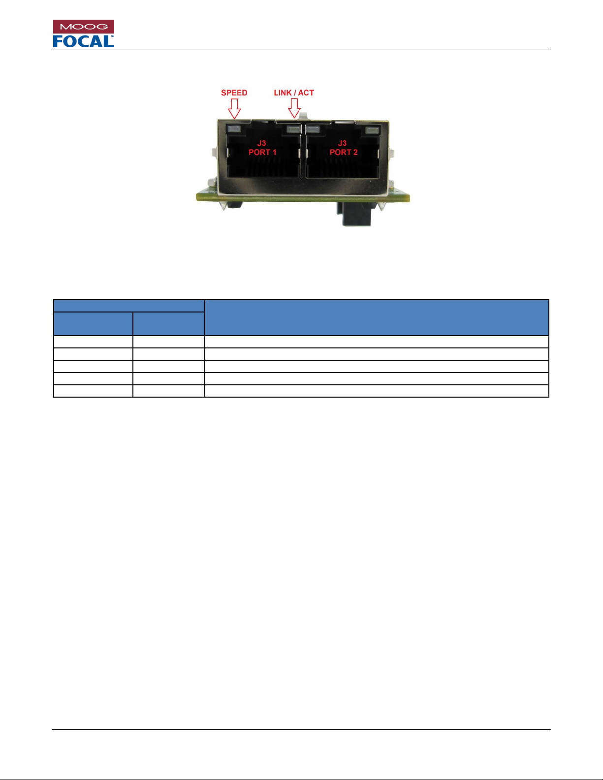
Model 914-X Series Modular Multiplexer System User Manual
Focal Technologies Corporation Page 6-11
A Moog Inc. Company Document Number: 914-0601-00 Rev. 5.0
6.2.2 914-EX Ethernet RJ45 LEDs
Figure 6-15: Ethernet Ports
Integrated LEDs show Ethernet Link Status as shown in Table 4-5.
Table 6-8: Ethernet LEDs
LED Status
Function
Left
Green/Orange
Right
Yellow
OFF*
X
10 BASE-T
ORANGE
X
100 BASE-TX
GREEN
X
1000 BASE-T
X
ON
LINKED
X
FLASHING
LINKED WITH ACTIVITY
* Speed indication only valid when link LED is on or flashing.
Page 53
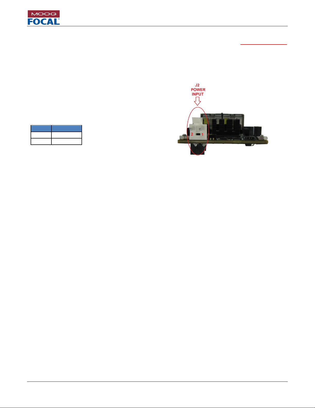
Model 914-X Series Modular Multiplexer System User Manual
Focal Technologies Corporation Page 6-12
A Moog Inc. Company Document Number: 914-0601-00 Rev. 5.0
6.2.3 914-EX Power
Power to the 914-EX card is provided via the expansion connector J9. Power input connect J2 should not be used
during normal operation with the 914-EX. It can optionally be used for standalone operation during firmware updates
or configuration.
If the 914-EX is to be self-powered, this is accomplished via connector J2, Molex P/N 09-75-2024. The mating plug
is Molex P/N 26-03-4020 with crimps P/N 08-52-0113. The pinout is provided in the table and figure below.
Figure 6-16: Factory Power Input Connector Location
The recommended input voltage range is 4.5 VDC to 13.0 VDC (typically +5 VDC regulated). Nominal power
consumption is 3.5 W, increasing to 4.2 W at 60o C ambient temperature with both ports linked at 1000 BASE-T.
Power leads should be AWG 18 – 20.
The onboard surface mount fuse, F1, is rated to 2A and is not intended to be field replaceable. If the power fuse
is blown, the card should be evaluated for damage by the factory or trained service personnel prior to any repair.
Pin #
Function
1
GND
2
VCC
Table 6-9: Power
Connector Pinout
Page 54

Model 914-X Series Modular Multiplexer System User Manual
Focal Technologies Corporation Page 6-13
A Moog Inc. Company Document Number: 914-0601-00 Rev. 5.0
6.2.4 914-EX Diagnostic LEDs
The 914-EX card includes 6 on-board diagnostic LEDs. A description and location of each LED is provided in Table
4-7 and Figure 4-8.
Table 6-10: 914-EX Diagnostic LEDs
Reference
Designator
Color
Description
D2
Red
Power Fault. Only lit if power is sourced via J2 and input voltage is outside nominal 4.5
to 13.0 VDC.
D3
Green
Power. Lit when powered.
D4
Red
Primary Expansion channel fault. No link established to partner card via 914-HDE across
the optical link.
D5
Green
Primary Expansion channel link. Valid link established to partner card via 914-HDE
across the optical link.
D6
Red
Secondary Expansion channel fault. No link established to partner card via 914-HDE
across the optical link.
D7
Green
Secondary Expansion channel link. Valid link established to partner card via 914-HDE
across the optical link.
Figure 6-17: 914-EX Diagnostic LEDs
Page 55

Model 914-X Series Modular Multiplexer System User Manual
Focal Technologies Corporation Page 6-14
A Moog Inc. Company Document Number: 914-0601-00 Rev. 5.0
6.2.5 914-EX Diagnostic LED Header
The 914-EX card includes a 10-pin header capable of driving 8 LEDs. This is useful for LED integration into an
enclosure. Each LED pin is driven low to turn on an LED, and includes a 267 ohm resistor in series to limit the
current draw. Maximum current draw is 8 mA. Refer to section 4.7 for a sample connection diagram.
The LED header is FCI P/N 20021521-00010T1LF, and the mating part is FCI P/N 20021444-00010T1LF. This can
be used with most 0.050” (1.27mm) spacing ribbon cables.
Table 6-11: 914-EX Diagnostic LED Header Pinout
Pin
Name
Description
1
3.3V
3.3V
This pin can be used to drive the LEDs, Maximum current is
0.5A.
2
EXPANSION 1 LINK
Primary Expansion channel link. Valid link established to
partner card via 914-HDE across the optical link. Active low.
3
EXPANSION 1 FAULT
Primary Expansion channel fault. No link established to partner
card via 914-HDE across the optical link. Active low.
4
EXPANSION 2 LINK
Secondary Expansion channel link. Valid link established to
partner card via 914-HDE across the optical link. Active low.
5
EXPANSION 2 FAULT
Secondary Expansion channel fault. No link established to
partner card via 914-HDE across the optical link. Active low.
6
ETHERNET PORT 1 ACTIVITY
Activity present on Ethernet port 1. Active low.
7
ETHERNET PORT 1 LINK
Ethernet port 1 is linked. Active low.
8
ETHERNET PORT 2 ACTIVITY
Activity present on Ethernet port 2. Active low.
9
ETHERNET PORT 2 LINK
Ethernet port 2 is linked. Active low.
10
GND
Ground, non-isolated, connected to 914-HDE input voltage
ground.
Figure 6-18: Diagnostic LED Header
Page 56
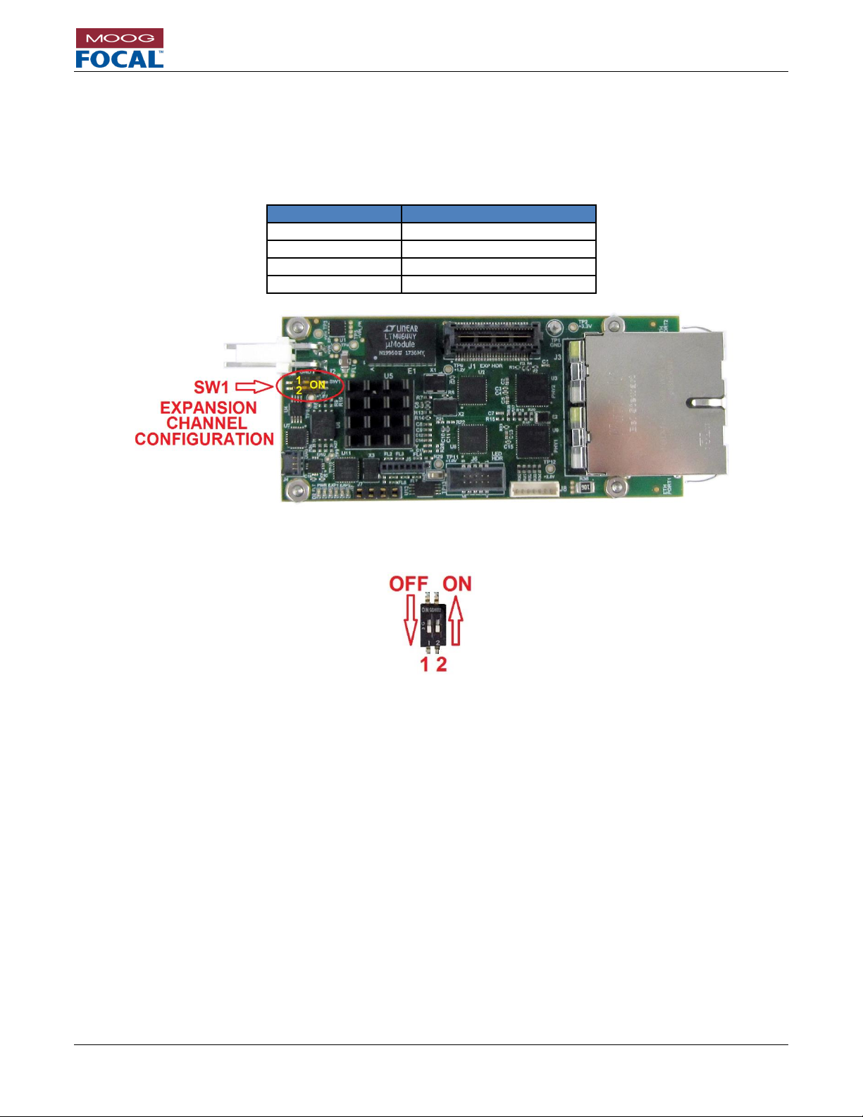
Model 914-X Series Modular Multiplexer System User Manual
Focal Technologies Corporation Page 6-15
A Moog Inc. Company Document Number: 914-0601-00 Rev. 5.0
6.2.6 914-EX Expansion Channel Configuration
Up to four 914-EX cards giving up to 8 additional Ethernet ports may be stacked on each 914-HDE, depending on
available optical bandwidth. Dip switch SW1 configures which expansion channel each card uses. The card closest
to the 914-HDE must be configured for expansion channel 1, with each subsequent card configured for the next
channel in succession. No channels may be skipped.
Table 6-12: 914-EX Expansion Channel Configuration
SW1[1:2]
Setting
OFF, OFF
Expansion channel 1
ON, OFF
Expansion channel 2
OFF, ON
Expansion channel 3
ON, ON
Expansion channel 4
Figure 6-19: Diagnostic LED Header
Figure 6-20: SW1 Position and Orientation
Page 57
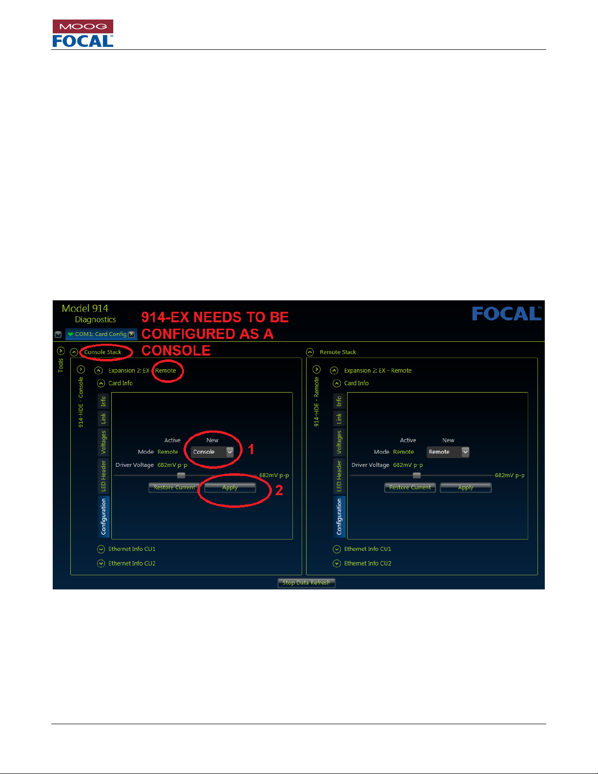
Model 914-X Series Modular Multiplexer System User Manual
Focal Technologies Corporation Page 6-16
A Moog Inc. Company Document Number: 914-0601-00 Rev. 5.0
6.2.7 914-EX Configuration
By default, all 914-EX cards are shipped with these settings:
Remote configuration
Both Ethernet ports set to auto-negotiate all speeds (10/100/1000M) and duplex settings (full/half)
Link fault pass-through disabled.
To change these settings, connect the console 914-HDE to the 914 Diagnostic GUI via a local COM port. Ensure a
stable optical link is present and the cards are stacked together in the correct order with the correct expansion
settings as per the previous section.
From the GUI, click on the “Card Info” then “Configuration” tab as shown in Figure 6-11. Since a 914-X Series
system requires a remote and console card and all 914-EX cards are shipped by default as remote, the user MUST
configure the 914-EX card that is installed at the console side as a console 914-EX (step 1). Once the desired “new”
settings are selected, press apply to save them to the card (step 2). Console cards should always be viewed on the
left side of the GUI.
The Driver Voltage indicates the drive strength for the expansion interface. For 914-EX cards that are distant from
the 914-HDE (either stacked at expansion channel 2+, or are using a high speed ribbon cable) it may be necessary
to boost this from the default setting of 682 mV. This setting should never be set below 682 mV.
Figure 6-21: 914-EX Location Configuration
Page 58

Model 914-X Series Modular Multiplexer System User Manual
Focal Technologies Corporation Page 6-17
A Moog Inc. Company Document Number: 914-0601-00 Rev. 5.0
6.2.8 914-EX Ethernet Port Configuration
To alter the Ethernet port 1 settings from the GUI, click on “Ethernet Info Cu1” then “Settings” tab as shown in Figure
6-12. Press ON or OFF for the desired settings and wait for each change to take effect. Figure 6-22 shows a Console
Ethernet port 1 that has 1000 BASE-T negotiation disabled. The process to alter Ethernet port 2 settings is the
same, but in the “Ethernet info Cu2” GUI section.
Figure 6-22: 914-EX Ethernet Port Configuration
Current Ethernet port link status is shown in the GUI in the “Status” tab as shown in Figure 6-23.
Figure 6-23: 914-EX Ethernet Port Link Status
Page 59

Model 914-X Series Modular Multiplexer System User Manual
Focal Technologies Corporation Page 6-18
A Moog Inc. Company Document Number: 914-0601-00 Rev. 5.0
6.2.9 914-EX Diagnostics
In a similar manner to the 914-HDE, the 914-EX has available diagnostics from the GUI including all voltages and
the junction temperature of the FPGA. Any value shown in green is operating within normal specification. Values in
red or yellow should be examined.
Figure 6-24: 914-EX Voltages and Temperature
Page 60

Model 914-X Series Modular Multiplexer System User Manual
Focal Technologies Corporation Page 6-19
A Moog Inc. Company Document Number: 914-0601-00 Rev. 5.0
6.3 914-AX
The 914-AX (Adaptable Interface Board Expansion) is an adaptor board to provide one data channel which can
support a range of existing AIB (Adaptable Interface Board) modules. These boards provide simple single channel
interface add-ons for serial data, sonar data, TTL signals, CAN bus or hydrophones. These ports are multiplexed
into the 914-HDE optical data stream. This expansion card bandwidth is included with the baseline 914-HDE
bandwidth, and uses 1 of the 4 Low Speed (LS) expansion channels.
Figure 6-25: 914-AX
Figure 6-26: 914-AX with AIB-232 Module (example)
Figure 6-26 shows an example where one (1) isolated RS-232 channel can be added via the on-board expansion
connector to the 914-HDE card. As shown, the small AIB module is plugged on top of the 914-AX card. Access to
the isolated RS-232 channel is via the 4-pin WAGO connector (shown at the bottom right corner).
6.3.1 914-AX AIB Module Options
Table 6-13: AIB Module Options
Module
ID
AIB
485
AIB
485
AIB
485
AIB
232
AIB
HYDRO
AIB
ARCNET
AIB
MS900
AIB
CANBUS
Signal
RS-485
RS-422
TTL
RS-232
Hydro-
phone
Tritech
ARCNET
MS900
Sonar
CAN bus
AIB
Module
Part
Number
903-0252-00
903-0252-00
903-0252-01
903-0251-00
903-0244-00
903-0261-00
903-0250-00
903-0297-00
Please refer to 700-0271-00 AIB Plug-in Module User Guide for details and configurations.
Page 61

Model 914-X Series Modular Multiplexer System User Manual
Focal Technologies Corporation Page 6-20
A Moog Inc. Company Document Number: 914-0601-00 Rev. 5.0
6.3.2 914-AX AIB Module Installation
When installing an AIB module onto the 914-AX across connectors J5 and J6, always ensure the white dots on both
the AIB module and the 914-AX line up for proper orientation.
Figure 6-27: AIB Module Orientation
Page 62

Model 914-X Series Modular Multiplexer System User Manual
Focal Technologies Corporation Page 6-21
A Moog Inc. Company Document Number: 914-0601-00 Rev. 5.0
6.3.3 914-AX Interface Connector
The pinout of the WAGO connector P/N 733-364 on the 914-AX card is dependent on the installed AIB module.
Table 6-14: 914-AX Interface Connector Pinouts
PIN
AIB-485
(RS-485)
AIB-485
(RS-422)
AIB-485
(TTL)
AIB-232
(RS-232)
AIBHYDRO
(ANALOG)
AIBARCNET
(TRITECH)
AIBMS900
(SONAR)
AIBCANBUS
(CAN bus)
1
A (+)
+RX
INPUT
ISOGND
CHASSIS
CHASSIS
CHASSIS
CAN H
2
B (-)
-RX
N/C
RXD
N/C
LAN A
N/C
CAN L
3
N/C
+TX
OUTPUT
TXD
HYDRO-
LAN B
SONAR
BUS
(GND)
4
N/C
-TX
ISOGND
CHASSIS
HYDRO+
N/C
SONAR
Shield
Figure 6-28: 914-AX WAGO Connector
Headers for the external connections are all four-pin, right-angled 733 series WAGO connectors (mating WAGO
connectors are P/N 733-104). Pin locations of the WAGO headers are shown in Figure 6-28. Corresponding pins
of the mating connector, use cage clamps rather than screw terminals to hold wires in place. External wires should
be 20-28 AWG stranded conductors with 0.22” - 0.24” stripped ends. The clamp for each pin can be opened up by
inserting either a WAGO tool or a small screwdriver in the hole immediately above the wire hole.
Table 6-15: 914-AX WAGO Connector Mating Plug
Page 63

Model 914-X Series Modular Multiplexer System User Manual
Focal Technologies Corporation Page 6-22
A Moog Inc. Company Document Number: 914-0601-00 Rev. 5.0
6.3.4 914-AX Diagnostic LEDs
The 914-AX card includes 3 on-board diagnostic LEDs. A description and location of each LED is provided in Table
4-7 and Figure 6-29.
Table 6-16: 914-AX Diagnostic LEDs
Reference
Designator
Color
Description
D3
Green
Power. Lit when power is received via the expansion connector.
D4
Green
AIB Tx data. Tx refers to transmit from the 914-AX.
D5
Yellow
AIB Rx data. Rx refers to receive at the 914-AX.
Figure 6-29: 914-AX Diagnostic LEDs
Page 64

Model 914-X Series Modular Multiplexer System User Manual
Focal Technologies Corporation Page 6-23
A Moog Inc. Company Document Number: 914-0601-00 Rev. 5.0
6.3.5 914-AX Diagnostic LED Header
The 914-AX card includes a 10-pin header capable of driving 8 LEDs. This is useful for LED integration into an
enclosure. Each LED pin is driven low to turn on an LED, and includes a 267 ohm resistor in series to limit the
current draw. Maximum current draw is 8 mA. Refer to section 4.7 for a sample connection diagram.
The LED header is FCI P/N 20021521-00010T1LF, and the mating part is FCI P/N 20021444-00010T1LF. This can
be used with most 0.050” (1.27mm) spacing ribbon cables.
Table 6-17: 914-AX Diagnostic LED Header Pinout
Pin
Name
Description
1
3.3V
3.3V
This pin can be used to drive the LEDs, Maximum current is
0.5A.
2
AIB TX DATA
Data is transmitting from the AIB module. Active low.
3
AIB RX DATA
Data is received at the AIB module. Active low.
4
N/C
N/C
5
N/C
N/C
6
N/C
N/C
7
N/C
N/C
8
N/C
N/C
9
N/C
N/C
10
GND
Ground, non-isolated, connected to 914-HDE input voltage
ground.
Figure 6-30: 914-AX Diagnostic LED Header
Page 65
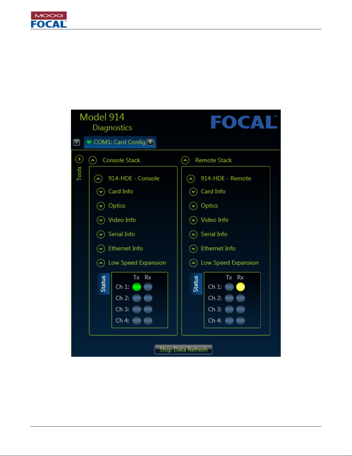
Model 914-X Series Modular Multiplexer System User Manual
Focal Technologies Corporation Page 6-24
A Moog Inc. Company Document Number: 914-0601-00 Rev. 5.0
6.3.7 914-AX Configuration and Diagnostics
The 914-AX does not require any specific configuration, however, the installed AIB module may require
configuration. Please refer to the AIB Plug-In Modules User’s Guide 700-0271-00 for configuration details specific
to the installed AIB module.
Up to four 914-AX with associated AIB modules may be added to a 914-HDE system. The 914-AX closest to the
914-HDE will show up as channel one in the diagnostic GUI. Tx and Rx activity status may be observed via the
914-HDE diagnostics in the “Low Speed Expansion” tab.
Figure 6-31: 914-AX Data Activity
Page 66

Model 914-X Series Modular Multiplexer System User Manual
Focal Technologies Corporation Page 6-25
A Moog Inc. Company Document Number: 914-0601-00 Rev. 5.0
6.4 914-DX (Preliminary Information)
The 914-DX provides 6 channels of isolated serial data. The serial channels are isolated in pairs and can each be
individually configured for RS-232, RS-485 or RS-422. The 914-DX does not require additional bandwidth from the
914-HDE as it is already included with the standard 914-HDE bandwidth calculation. Diagnostics from this card are
provided to the 914-HDE and is available to the Model 914 Diagnostic GUI. This expansion card requires 1 low
speed expansion channel. Consult factory for more information.
6.5 Custom 914-X Series
The 914-HDE expansion connector has been designed to enable future upgrades and addition of new 914-X Series
cards that can be developed in the future to support other types of electrical signals or protocols. Please contact
Moog Focal to discuss other applications or custom board needs.
Page 67
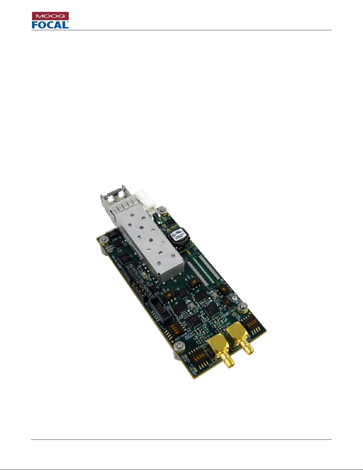
Model 914-X Series Modular Multiplexer System User Manual
Focal Technologies Corporation Page 7-1
A Moog Inc. Company Document Number: 914-0601-00 Rev. 5.0
7.0 914 Media Converters
Media converters provide conversion of high bandwidth signals to fiber on a 1:1 basis. These are useful additions
to systems as upgrades, or act as standalone optical converters for simple systems with only a single data type.
Media converter cards may be added to a 914-HDE system using the same standoffs and 21/32” (16.67 mm)
spacing as other 914-HDE system cards when directly stacked together. Media converter cards do not require an
electrical link to 914-HDE system cards, or other media converter cards other than the fiber optic link when using a
CWDM module.
7.1 914-HDV2
The Moog Focal Model 914-HDV2 is a standalone media converter solution for one or two 3G/HD/SD-SDI video
feeds per card. This card has the same form factor and mounting requirements as the rest of the 914-HDE series,
and can have the optical signals combined with a 914-HDE system via available optical CWDM cards.
The compact size and high optical budget make the 914-HDV2 an ideal solution for long distance transmission of
uncompressed low latency video signals. 4K video over dual link 3G-SDI is supported using a single 914-HDV2,
and multiple 914-HDV2 cards may be combined for transmission of 4K video over quad link 3G-SDI.
Figure 7-1: 914-HDV2
Page 68

Model 914-X Series Modular Multiplexer System User Manual
Focal Technologies Corporation Page 7-2
A Moog Inc. Company Document Number: 914-0601-00 Rev. 5.0
Figure 7-2: 914-HDV2 Interface Locations and Pin Numbering
7.1.1 914-HDV2 Video Connections
The 914-HDV2 card has two video ports, supporting 3G/HD/SD-SDI video conforming to SMPTE 259M-C, SMPTE
292M, and SMPTE 424M. On the remote card the video channels are inputs, and on the console they are outputs.
The connectors are a Mini SMB jack, Amphenol P/N 142146-75. Recommended mating plug is Cinch P/N 1318403-101, although other 75 Mini SMB plugs may be suitable. Cabling should be RG-179, 75 coaxial type.
Video latency through the media converter system is less than 1 s, not including fiber delays of 5 ns/m.
Figure 7-3: Mini SMB Jack - Amphenol P/N 142146-75
Figure 7-4: Video I/O Locations
7.1.2 914-HDV2 Optical Connections
914-HDV2 cards typically use dual transmitter optics at the remote end, and dual receivers at the console. Note
that the channel nomenclature is inverted when switching configurations.
For single channel 914-HDV2 configurations, the CH1 location (only) should be used.
Page 69
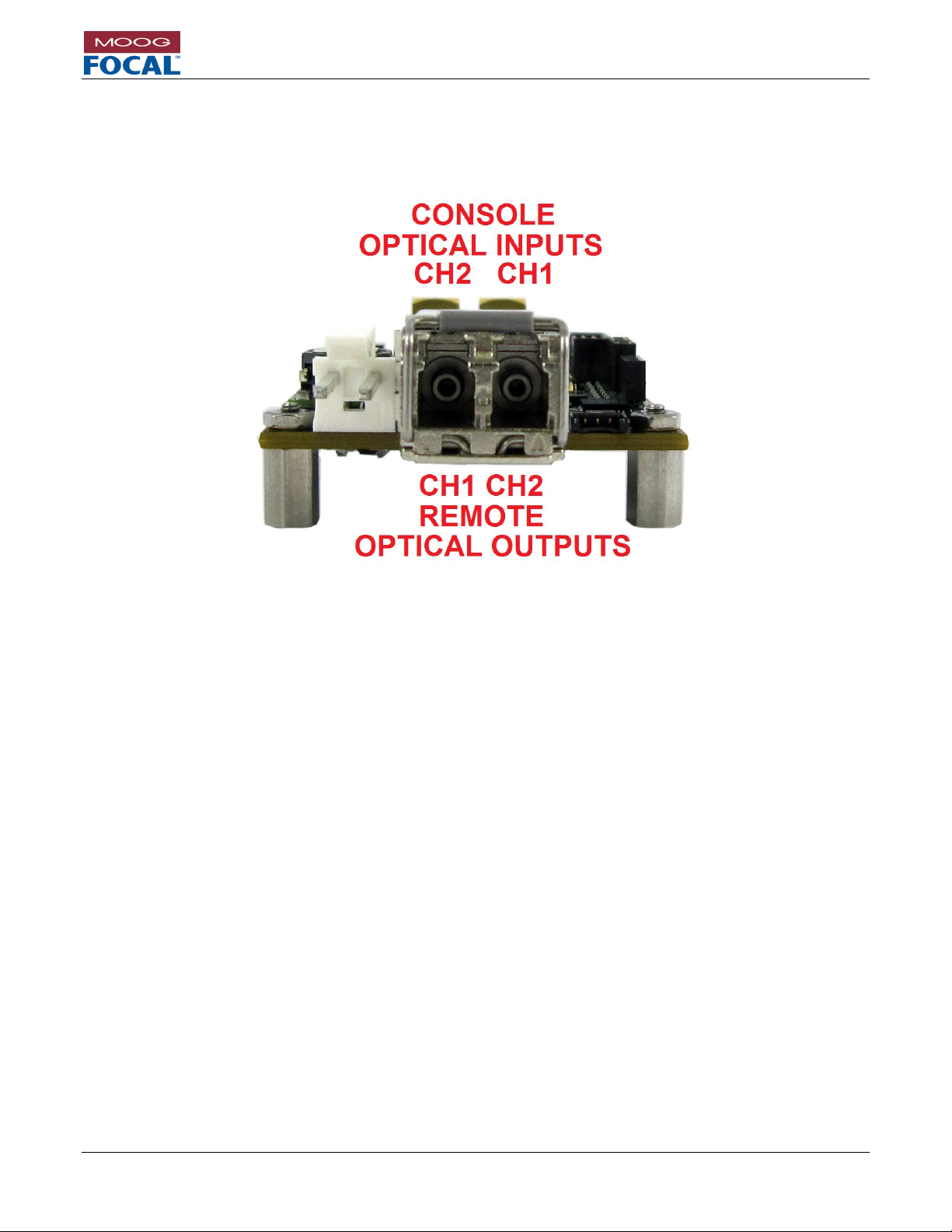
Model 914-X Series Modular Multiplexer System User Manual
Focal Technologies Corporation Page 7-3
A Moog Inc. Company Document Number: 914-0601-00 Rev. 5.0
All versions of the 914-HDV2 use high powered optical transceivers, a minimum link loss or attenuation of 10 dB is
suggested.
Bushings on the SFP optical transceiver are standard LC. Fiber type is singlemode.
Figure 7-5: 914-HDV2 Optical Interface
Page 70

Model 914-X Series Modular Multiplexer System User Manual
Focal Technologies Corporation Page 7-4
A Moog Inc. Company Document Number: 914-0601-00 Rev. 5.0
7.1.3 914-HDV2 Power
Power to the 914-HDV2 card is provided through connector J2, Molex P/N 09-75-2024. The mating plug is Molex
P/N 26-03-4020 with crimps P/N 08-52-0113. The pinout is provided in the table and figure below.
Figure 7-6: Power Input Connector Location
The recommended input voltage range is 4.5 VDC to 13.0 VDC (typically +5 VDC regulated). Nominal power
consumption is 2.8 W, increasing to 3.2 W at 60o C ambient temperature. Power leads should be AWG 18 – 20.
The onboard surface mount fuse, F1, is rated to 2A and is not intended to be field replaceable. If the power fuse
is blown, the card should be evaluated for damage by the factory or trained service personnel prior to any repair.
Pin #
Function
1
GND
2
VCC
Table 7-1: Power
Connector Pinout
Page 71
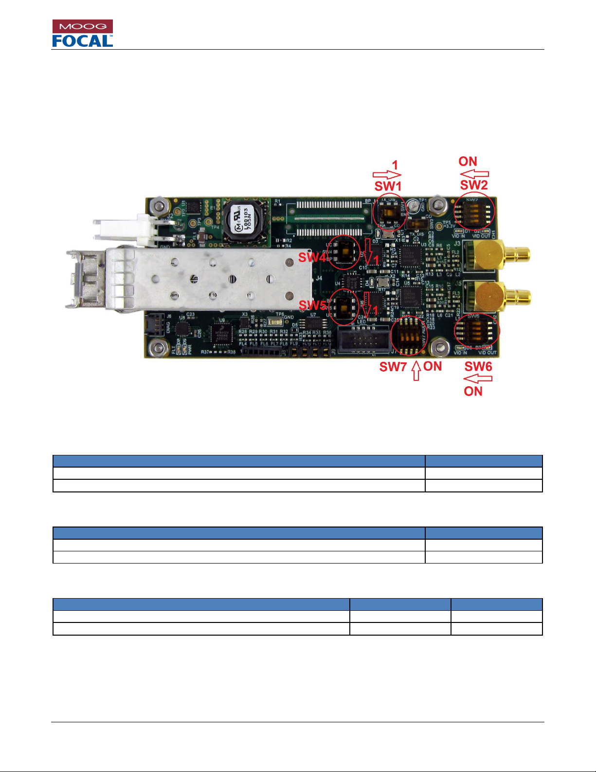
Model 914-X Series Modular Multiplexer System User Manual
Focal Technologies Corporation Page 7-5
A Moog Inc. Company Document Number: 914-0601-00 Rev. 5.0
7.1.4 914-HDV2 Configuration
The 914-HDV2 is configured via dip switches, and not by software. Dip switches are pre-set to the appropriate
settings based on the as shipped configuration and part number. MSA refers to single video channel assemblies
using standard SFP transceivers, non-MSA refers to dual uni-directional transceivers that are default for the 914HDV2. There are hardware differences between the MSA and non-MSA boards, do not alter the switch settings
without consulting Moog Focal. The exception is SW2 and SW6 EQ and CD settings. This can be tuned to the video
resolution and cable lengths as required.
Figure 7-7: 914-HDV2 Configuration Dip Switches
Table 7-2: SW1 - SFP Transmitter Disable Non-MSA Mode
Function
SW1 Position
SFP Transmitter Disabled when no video is present (default)
1
SFP transmitter is always enabled, or MSA mode
2
Table 7-3: SW3 - SFP Transmitter Disable MSA Mode
Function
SW3 Position
SFP Transmitter Disabled when no video is present (default)
1
SFP transmitter is always enabled
2
Table 7-4: SW4 and SW5 Factory Programming Mode
Function
SW4 Position
SW5 Position
Factory Programming Mode
1
1
Diagnostics Mode (default)
2
2
Page 72
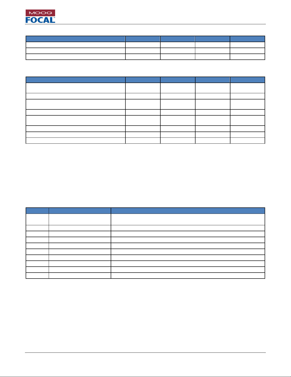
Model 914-X Series Modular Multiplexer System User Manual
Focal Technologies Corporation Page 7-6
A Moog Inc. Company Document Number: 914-0601-00 Rev. 5.0
Table 7-5: SW7 - DIAGNOSTICS IN MSA OR NON-MSA
Function
SW7[1]
SW7[2]
SW7[3]
SW7[4]
Diagnostics Mode (default)
OFF
OFF
OFF
N/A
Non-MSA Mode (default)
N/A
N/A
N/A
OFF
MSA Mode
N/A
N/A
N/A
ON
Table 7-6: SW2 (Channel 1) and SW6 (Channel 2): Input EQ or Output Cabled Driver Settings
Function
SWx[1]
SWx[2]
SWx[3]
SWx[4]
Video Output CD Mode
OFF
(CONSOLE)
N/A
N/A
N/A
Video Input EQ Mode
ON (REMOTE)
N/A
N/A
N/A
EQ Gain Normal
N/A
OFF
(DEFAULT)
N/A
N/A
EQ Gain Boost 6dB
N/A
ON
N/A
N/A
EQ Enabled
N/A
N/A
OFF
(DEFAULT)
N/A
EQ Bypass
N/A
N/A
ON
N/A
Cable driver in SD Mode
N/A
N/A
N/A
OFF
Cable driver in HD Mode (console)
N/A
N/A
N/A
ON (DEFAULT)
7.1.5 914-HDV2 Diagnostic LED Header
The 914-HDV2 card includes a 10-pin header capable of driving 8 LEDs. This is useful for LED integration into an
enclosure. Each LED pin is driven low to turn on an LED, and includes a 267 ohm resistor in series to limit the
current draw. Maximum current draw is 8 mA.
The LED header is FCI P/N 20021521-00010T1LF, and the mating part is FCI P/N 20021444-00010T1LF. This can
be used with most 0.050” (1.27mm) spacing ribbon cables.
Table 7-7: 914-HDV2 Diagnostic LED Header J7 Pinout
J7 Pin
Name
Description
1
3.3V
3.3V
This pin can be used to drive the LEDs, Maximum current is 0.5A.
2
RX OPT LINK
Receive Optical Link Valid (MSA SFP only). Active low.
3
VID CH1 CD
Video Channel 1 Carrier Detect. Remote side only. Active low.
4
VID CH2 CD
Video Channel 2 Carrier Detect. Remote side only. Active low.
5
FAULT
Fault. (no SFP, No I2C diagnostics) Active low.
6
RX OPT LINK CH2
Receive Channel 2 Optical Link Valid (non-MSA SFP only). Active low.
7
RX OPT LINK CH1
Receive Channel 1 Optical Link Valid (non-MSA SFP only). Active low.
8
VID CH1 VALID
Video Channel 1 output is valid. Console only. Active low.
9
VID CH2 VALID
Video Channel 2 output is valid. Console only. Active low.
10
GND
Ground
Page 73
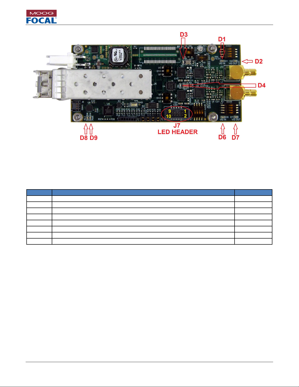
Model 914-X Series Modular Multiplexer System User Manual
Focal Technologies Corporation Page 7-7
A Moog Inc. Company Document Number: 914-0601-00 Rev. 5.0
Figure 7-8: 914-HDV2 Diagnostic LEDs and LED Header
7.1.6 914-HDV2 Diagnostic LEDs
The 914-HDV2 card includes 8 on-board diagnostic LEDs. A description and location of each LED is provided in
Figure 7-8 and Table 7-8.
Table 7-8: 914-HDV2 Diagnostic LEDs
LED
Description
Colour
D1
Video channel 1 input valid (remote)
Yellow
D2
Video channel 1 output valid (console)
Green
D3
Video channel 1 lock detect (remote)
Green
D4
Video channel 2 lock detect (remote)
Green
D6
Video channel 2 input valid (remote)
Yellow
D7
Video channel 2 output valid (console)
Green
D8
Power Fault. Outside of +4.5 V to +13.0 V range.
Red
D9
Power Good
Green
Page 74

Model 914-X Series Modular Multiplexer System User Manual
Focal Technologies Corporation Page 7-8
A Moog Inc. Company Document Number: 914-0601-00 Rev. 5.0
7.1.7 914-HDV2 Diagnostics
914-HDV2 has its own GUI and diagnostic connection separate from the 914-HDE motherboard. This diagnostic
GUI cannot alter settings, nor can it access remote side diagnostics. It does give information regarding the health
of the fiber links, the status of the video channels, and some standard board level diagnostics including voltages
and temperatures. It also gives software access to all LED status.
Access to the RS232 diagnostic interface is via connector J6. Please refer to Section 5.0 for more information
regarding this connector, pinout and cabling.
914-HDV2 diagnostic GUI part number is 914-0415-00 available via the Moog Focal website.
Figure 7-9: 914-HDV2 Optical Diagnostics
Page 75

Model 914-X Series Modular Multiplexer System User Manual
Focal Technologies Corporation Page 7-9
A Moog Inc. Company Document Number: 914-0601-00 Rev. 5.0
Figure 7-10: 914-HDV2 PCBA Diagnostics
Figure 7-11: 914-HDV2 Video Diagnostics
Figure 7-12: 914-HDV2 LED Diagnostics
Page 76

Model 914-X Series Modular Multiplexer System User Manual
Focal Technologies Corporation Page 8-1
A Moog Inc. Company Document Number: 914-0601-00 Rev. 5.0
8.0 914 Optical Cards
8.1 914-CWDM
The 914-CWDM allows a standard 1310 / 1550 nm bidirectional single fiber system to be upgraded with two new
wavelengths. The standard upgrade is for 1471 / 1491 nm which can be used for a second 914-HDE system or for
a 914-HDV2 dual HD video upgrade.
8.2 914-CWDM-4R1
The 914-CWDM-4R1 allows four standard red band wavelengths to be combined onto a single fiber. A blue band
bypass is optional for system upgrades. 1471 / 1491 / 1511 / 1531 nm are the four multiplexed wavelengths. Other
wavelength options are possible. Contact Moog Focal for part numbers.
8.3 914-CWDM-8R
The 914-CWDM-8R allows all eight standard red band wavelengths to be combined onto a single fiber. A blue band
bypass is optional for system upgrades.
1471 / 1491 / 1511 / 1531 / 1551 / 1571 / 1591 / 1611 nm are the eight multiplexed wavelengths (red band).
8.4 914-SPLIT
The single fiber link can be split onto 2 fibers for communication and fiber redundancy. Please contact Moog Focal
for details.
8.5 914-FOS
Redundant fiber systems integrate a switch to choose which fiber is active. Please contact Moog Focal for details.
Page 77

Model 914-X Series Modular Multiplexer System User Manual
Focal Technologies Corporation Page 9-1
A Moog Inc. Company Document Number: 914-0601-00 Rev. 5.0
9.0 Moog Focal Optical Transceivers
Moog Focal OEM SFP optical transceivers are available for sparing, replacements, and upgrades. Pressure tolerant
versions of the 4.25 Gbps SFPs are available.
Table 9-1: SFP Optical Transceiver Options
4.25 Gbps
Bi-Directional SFP
4.25 Gbps
CWDM
SFP
10.3 Gbps
Bi-Directional SFP
10.3 Gbps
CWDM
SFP
Wavelengths (nm)
1310 / 1550
All 18 CWDM
wavelengths
1270 / 1330
All 8 red CWDM
wavelengths
Connector Type
Single LC
bi-directional
Dual LC
Tx / Rx
Single LC
bi-directional
Dual LC
Tx / Rx
Fiber Type
Singlemode
Singlemode
Singlemode
Singlemode
Min bit rate (Gbps)
0.125
0.125
0.6
0.6
Max bit rate
(Gbps)
4.25
4.25
10.3
10.3
Max Distance (km)
10
10
10
10
Optical budget
(dB)
20
24
20
23
Tx Power (dBm)
min
0 0 0
0
Rx Sensitivity
(dBm)
- 20
-24
-20
-23
Case Operating
temperature (C)
-40 to +85
-20 to +85
-40 to +85
-20 to +75
Available as
pressure tolerant
Yes
Max 3000 PSI
Yes
Max 6000 PSI
No
No
Compatibility
914-HDE L1/M1
914-HDE L1/M1
914-HDE H1
914-HDE H1
Refer to Section 13.9 for part numbers.
Page 78

Model 914-X Series Modular Multiplexer System User Manual
Focal Technologies Corporation Page 10-1
A Moog Inc. Company Document Number: 914-0601-00 Rev. 5.0
10.0 914-X Series System Installation and Operation
10.1 Installation
The 914-X Series is intended to be installed in an enclosure with access to conductive cooling, or in an environment
with airflow. 914-X Series is designed to ensure low power consumption and tolerance of wide operating
temperatures. It is, however, the responsibility of the system integrators to ensure that adequate cooling is provided
to the units. In particular, the optical transceiver (J5) must not exceed a case temperature of +85 C and the FPGA,
U5, should not exceed a junction temperature of +100 C as reported by the diagnostic GUI. To accomplish this, it
is recommended to provide direct conductive cooling to the four mounting holes. Recommended mounting hardware
is #2-56 type and is included with the cards. Ensure any mating hardware (standoffs, nuts, washers) are fully clear
of any onboard parts, solder joints, and electrical traces. Thermally conductive hardware is recommended for
mounting the card stacks. The mounting holes are electrically isolated from the system ground and are connected
to a thermal layer in the PCB. These mounting holes should be used to provide conductive cooling to the PCB.
Stacking height for expansion cards is 16.00 mm to 17.22 mm. Nominal height should be minimum 16.15 mm
(0.636”) to take into account component tolerances. A 4.00 mm (minimum) standoff should be used under the 914HDE to ensure bottom side components have sufficient clearance. Standard 5/32” standoffs are supplied with the
914-HDE for mounting, along with 21/32” standoffs for expansion and media converter cards. Thermal gap material
should be used under the 914-HDE to further extract heat from the card.
Figure 10-1: 914-HDE Dimensions
When mounting, disassembling, or reassembling the 914-HDE (and stack), ensure that no fibers are subjected to
bends in excess of those held by the natural routing of the fibers. The minimum bend radius of the fibers should be
no less than 25 mm, though single partial bends may be less than this – as low as 15 mm – without damaging the
fiber. Allowable long term values for bend radius are dependent on the fiber type and environment. Avoid even
temporary bends with a radius less than 15 mm, which may affect the long-term reliability of the fiber.
To ensure that the system maintains link and reliability through high shock and/or vibration environments, it is
recommended to secure the fiber LC connectors in the transceiver bushings using MIL-A-46146 equivalent RTV,
such as Dow Corning 3145 clear RTV. RTV may also be applied to power and data connectors, if required.
Page 79

Model 914-X Series Modular Multiplexer System User Manual
Focal Technologies Corporation Page 10-2
A Moog Inc. Company Document Number: 914-0601-00 Rev. 5.0
10.2 Card Stacking
Expansion cards are stacked using the expansion connectors as a high speed backplane system. Ensure the
orientation of the cards match, and observe the genders of the expansion connectors. Male connectors are always
on the top (component) side of the board, and female connectors on the bottom.
1. Bench level testing of the 914-HDE system should be performed prior to permanent installation of the cards
using Loctite and/or epoxy. This will allow all interfaces to be configured and tested with the user equipment
prior to committing to the assembled hardware configuration.
2. Mounting order:
a. Top card: Optical card(s) [914-CWDM; 914-FOS; 914-SPLIT]
b. Media converter card(s) [914-HDV2]
c. Low speed expansion card(s) [914-AX; 914-DX]
d. Medium speed expansion Card(s) [914-VDX; 914-EX]
e. Base card: Motherboard [914-HDE]
3. Install the 914-HDE Motherboard to a suitable mounting plate.
a. Use the 5/32” standoffs with thermal gap material under the card to provide a good conductive
cooling path to the mounting plate and/or enclosure.
b. Alternatively ensure there is adequate airflow to provide cooling to the 914-HDE Motherboard.
c. If no expansion cards are required, install the supplied nuts with Loctite 290 (or similar).
d. If expansion cards are required, move to step 4.
4. Install the supplied 21/32” standoffs with Loctite 242 (or similar) to the 914-HDE or 914 card directly under
the next expansion card.
a. Stack the expansion card carefully onto the expansion header while lining up the standoffs to the
mounting holes. The card should seat directly down on all sides simultaneously with little
resistance.
b. Optionally install a 914-HDE high speed ribbon cable with Loctite SI 595 CL RTV for expansion
connector retention. Refer to Section 10.3 for details.
i. Complete the first card with supplied nuts and Loctite 290 or similar.
ii. Start the next stack with the male end of the ribbon cable epoxied to the bottom side female
expansion connector. Use Loctite SI 595 CL RTV to retain this connector in place.
iii. Start the new stack with supplied 21/32” standoffs.
c. Repeat step 4 for each Expansion card.
5. Complete the stack with supplied nuts and Loctite 290 (or similar) to retain the top card.
Figure 10-2: 914-X Series System Stack
Page 80
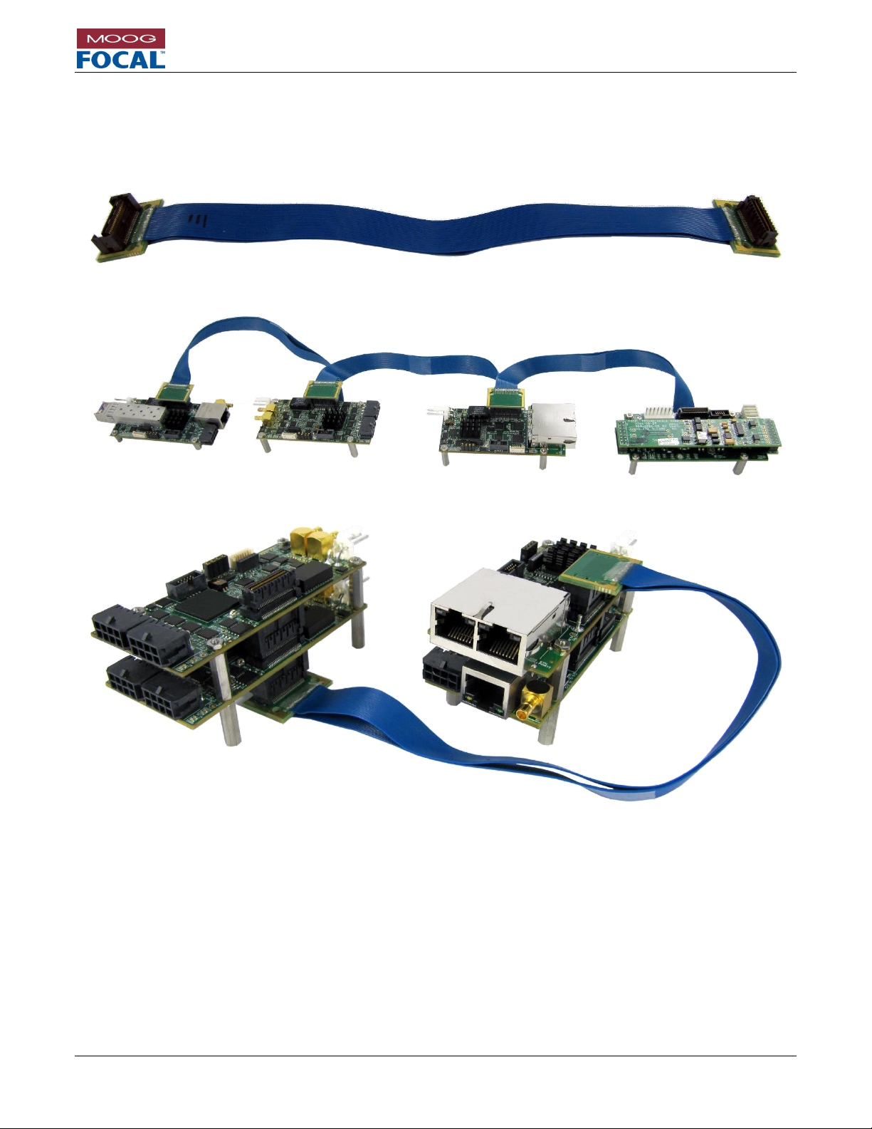
Model 914-X Series Modular Multiplexer System User Manual
Focal Technologies Corporation Page 10-3
A Moog Inc. Company Document Number: 914-0601-00 Rev. 5.0
10.3 914-X Series Expansion Interface Ribbon Cables
When specifying a large stack to fit into a small enclosure or pressure bottle, it may be desirable to break the stack
into smaller pieces. This can be accomplished with Moog Focal 914-X Series expansion interface high speed ribbon
cables. Specify lengths from 3” to 18” with orientations for inline mounting vs side-to-side mounting.
Figure 10-3: 914-X Series Expansion Interface High Speed Ribbon Cable
Figure 10-4: 914-X Series Linear (inline) Layout
Figure 10-5: 914-X Series System Dual Stack (side-to-side) Layout
Many other configurations are possible, these are representative examples.
Page 81

Model 914-X Series Modular Multiplexer System User Manual
Focal Technologies Corporation Page 10-4
A Moog Inc. Company Document Number: 914-0601-00 Rev. 5.0
10.4 914-X Series Bench Test
Basic Link Operation
Basic operation of the uplink (remote to console) and downlink (console to remote) can be verified in a bench test
simply by connecting fiber jumpers between the optical transceivers. The number of jumpers and the optical
attenuation required depends on the optical configuration of the system under test. In some optical configurations,
it may be required to use 5 or 10 dB optical attenuators placed between the fiber bushings on the mux (remote)
card and the bushings on the demux (console) card to ensure the optical receivers are not saturated. Complete a
flux budget calculation for your system, referring to the optical transmit power and receive overload level to
determine whether optical attenuation is required or not.
After power is applied to the 914-HDE, the power LED D6 should be on (green). A red Link Fault LED D9 indicates
insufficient received optical power, typically due to excessive loss in the fiber link. Excessive loss may be caused
by poor fiber connections (contaminated bushings, damaged fiber, damaged ferrules) or excessive fiber bends.
CARE MUST BE TAKEN WHILE HANDLING FIBER. DO NOT TOUCH THE TIP OF THE FIBER CABLE
(FERRULE) SINCE CONTAMINATION WILL OCCOUR. ALL FIBER CONNECTIONS MUST BE INSPECTED AND
VERIFIED TO BE CLEAN PRIOR TO FINAL INSTALLATION.
If the basic optical link is present (LED D8 is on), there should be data continuity through the multiplexer system to
provide video and serial data links.
Optical Power Budget Test
1. To verify the console to remote flux budget (downlink), measure the transmit power of the console card by
connecting the optical output directly to a calibrated optical power meter using a short, low-loss, test jumper.
(Ensure the correct fiber type is used. All fibers must be of the same type. e.g. for SM normally 9 um core,
for MM 50 um or 62.5 um core)
2. Remove the test jumper and install a variable optical attenuator (VOAT) between the console and remote
cards.
3. Adjust the VOAT until the red Link LED on either one of the modules turns on, then reduce the loss to the
point where both green link LEDs are continuously on. A stable serial data connection is a good reference
point.
4. Measure the received optical power at the remote side by connecting that end of the VOAT to the optical
power meter. The difference between the transmit power previously measured and this receive measured
power is an estimate of optical power budget. A spool of fiber used with the VOAT can also be used to
simulate dispersion effects over long cable lengths.
5. Repeat steps 1-4 with connections reversed to verify the remote to console (uplink) optical budget.
Page 82
Model 914-X Series Modular Multiplexer System User Manual
Focal Technologies Corporation Page 10-5
A Moog Inc. Company Document Number: 914-0601-00 Rev. 5.0
10.5 914-X Series Electrical and Environmental Specifications
The tables below summarize the electrical power requirements and environmental specifications of standard
products. Cards can be configured and/or screened at the factory for extended performance, such as higher
operational temperatures.
Table 10-1: Electrical Specification
Electrical Specification
Min
Typ
Max
Units
Power Voltage (In)
4.5 5 13.0
Volts
Power 914-HDE
5.0
6.0*
Watts
Power 914-VDX**
2.9
3.6*
Watts
Power 914-EX**
3.5
4.2*
Watts
Power 914-AX**
0.1****
1.15*
Watts
Power 914-HDV2
2.8
3.2*
Watts
Table 10-2: Environmental Specification
Environmental Specification
Min
Typ
Max
Units
Temperature Range (Operational)
-10
+60***
Celsius
Temperature Range (Storage)
-50
+85
Celsius
Humidity
85% RH, non-condensing
Shock
30 g, 11 ms half sine, 3 axes
g
Vibration
5 g, 25-1000 Hz, 3 axes
g, Hz
* The maximum power is with a 12V input at +60oC.
** This power is in addition to the 914-HDE, all stacked cards and their associated power ratings must be combined
to calculate a total system power rating.
*** Higher operational temperatures are possible by using thermal management to ensure electronic parts do not
exceed a case temperature of +85oC.
**** 914-AX power is highly dependent on the AIB module installed.
Input amperage must not exceed 4 A, if close to 20 W is required, the power supply must use a higher nominal
voltage e.g. 12 V.
10.6 914-X Series Maintenance
The unit requires no routine maintenance or calibration for the specified performance. Maintenance of the units is
limited to cleaning the various components using the methods described below.
Dust or dirt on the cards can be blown off using compressed air. If severe contamination of the cards should occur,
they can be removed and cleaned using distilled water. Cards must be thoroughly dried before reapplying power.
In order to maintain optical performance, please refer to the following optical considerations.
Optical Considerations
1. Observe the bend radius of fiber optic cables at all times
When mounting, disassembling, or reassembling the cards in your system, ensure that no fibers are subjected
to bends in excess of those held by the natural routing of the fibers. The minimum bend radius of the fibers
should generally be no less than 25 mm, though single loops may be less than this – as low as 15 mm –
without damaging the fibers. Keep in mind that allowable values are dependent on the type of fiber and the
environment, and cable manufacturers typically specify the minimum bend radius. Avoid even temporary
bends with a radius less than 15 mm, which may induce cracks that affect long-term reliability of the fibers. In
general, fiber jumpers and pigtails should be periodically inspected for damage, such as nicks in the jackets
or excessive bends.
2. Ensure fiber optic components are of the same type
All jumpers, cables, connectors, couplers, and Fiber Optic Rotary Joints (FORJs) used in the external optical
system connecting the remote to console multiplexer must use the same type of fiber.
Page 83

Model 914-X Series Modular Multiplexer System User Manual
Focal Technologies Corporation Page 10-6
A Moog Inc. Company Document Number: 914-0601-00 Rev. 5.0
The 914-X Series system has singlemode SFP transceivers installed and therefore all components in the fiber
link should also be singlemode, typically Corning SMF-28 (9/125 µm) or equivalent. A single mismatched
jumper in the system may cause intermittent or persistent optical link errors. Do not rely on cable jacket or
connector colors alone to determine the type of optical fiber.
3. Use clean connectors
It is critical to ensure all fiber connectors are clean and free of dirt and debris. Even a small amount of dirt or
fluid contaminant may degrade link performance, and most reported optical link problems are due simply to
poor or contaminated optical connections.
Keep protective dust covers on fiber connectors and bushings when not in use.
Do not touch the white ceramic ferrules of the connectors with bare hands or objects, other than
cleaning materials.
Prior to making a fiber connection, clean the barrel and tip of the ferrule using a suitable solvent, such
as reagent grade isopropyl alcohol, and a lint free optics cleaning tissue, such as Kimwipes® EX-L.
Carefully dab any dirt or debris off the face of the ceramic ferrules. Excessive dirt may need to be
cleared with pressurized air from a can prior to wiping the ferrule to avoid scratching the fiber itself.
Do not used air from a compressor as it may be contaminated with oil.
During mating or unmating of fiber connectors with bushings, keep the connector aligned as straight
as possible. Avoid side loading the ceramic ferrule, which can crack the internal alignment sleeve in
the bushing.
It is recommended that each fiber connector is inspected with a handheld fiber microscope prior to
final assembly to ensure there are no scratches, pits, debris, or fluid contamination on the fiber face.
NEVER look into the end of a fiber when it is plugged into a transceiver or active
fiber, especially when using a magnifying instrument, such as a fiber microscope.
Figure 10-6 shows an LC connector which is a small form-factor fiber optic connector that uses a 1.25 mm
ferrule and incorporates a push-and-latch design similar to an RJ-45 connector. Error! Reference source not f
ound. shows an ST fiber optic connector that uses a 2.5 mm ferrule. The ST connector is latched into place
by twisting to engage a spring-loaded bayonet socket.
Figure 10-6: LC connector
Figure 10-7: ST connector
4. Maintain good optical connections
SFP optical transceivers typically have a transmit and receive optical bushing (LC type), which requires dual
fiber operation. The transmit side (Tx) and the receiver side (Rx) of a dual LC port SFP is shown in the figure
below.
Ferrule
Ferrule
Page 84
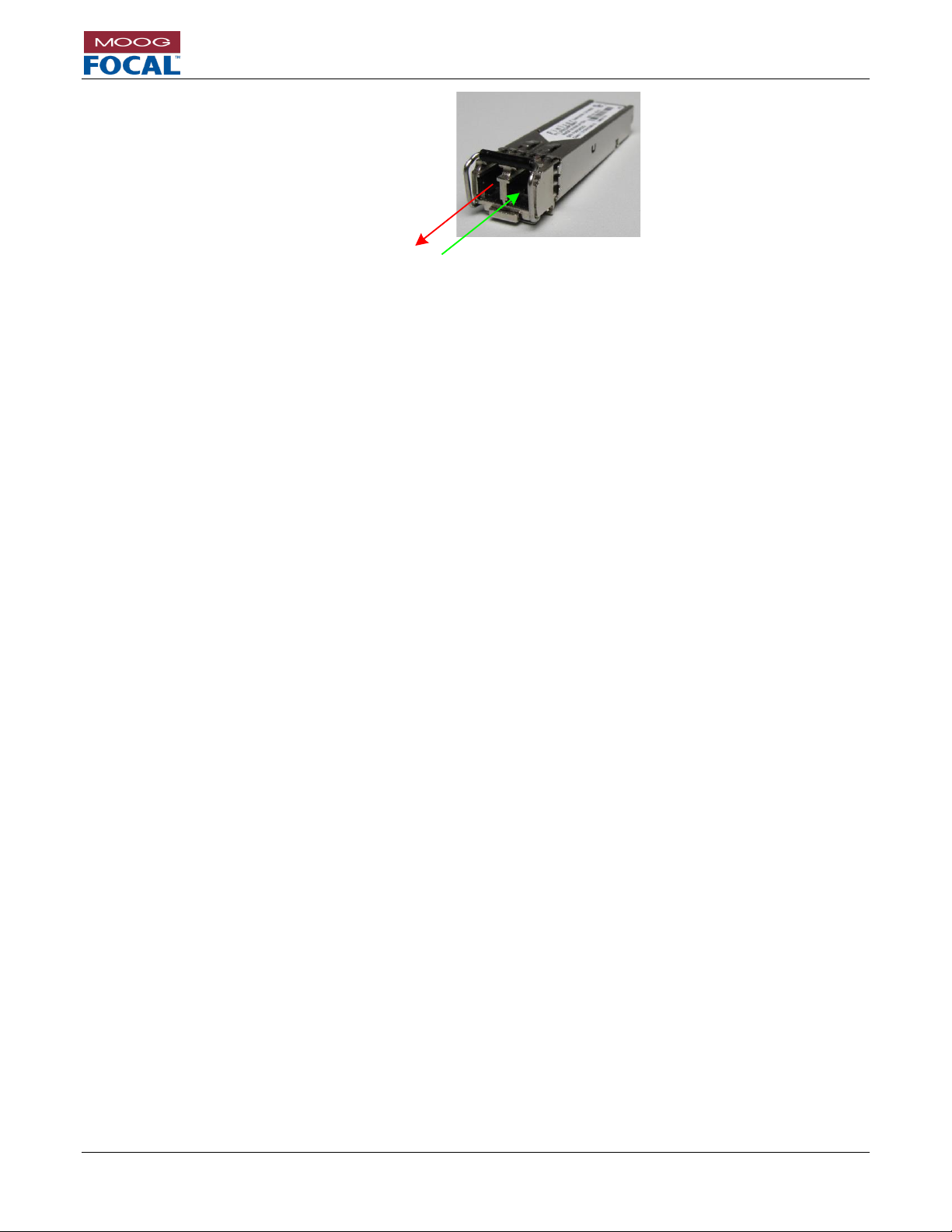
Model 914-X Series Modular Multiplexer System User Manual
Focal Technologies Corporation Page 10-7
A Moog Inc. Company Document Number: 914-0601-00 Rev. 5.0
Figure 10-8: SFP Transceiver (Dual LC)
5. Maintain proper optical power levels
Optical receivers will experience errors if the received optical power is too low. Ensure the total optical losses
of the components in the external cable system (jumpers, cable, connectors, couplers, FORJ, etc.) are less
than the specified optical power budget of your system. For any detailed measurements or trouble-shooting a
calibrated optical power meter should be used.
Optical receivers can also saturate and experience errors if the received optical power is too high, especially
when using high power transceivers. Use a 5 or 10 dB fixed attenuator in line with each fiber during bench
tests or with short, low loss links to ensure a minimum level of attenuation is present. A variable optical
attenuator (VOAT) can also be used for testing. In some high power systems, receivers can actually be
damaged by excessive optical power, so a fixed attenuator is recommended even with a VOAT.
10.7 914-X Series System Product Handling
General Handling
Care must always be taken during the handling of the 914-X Series cards to ensure product integrity. The following
guidelines should be observed while working with the card:
Handle products at an ESD safe workstation with a clean surface.
Ensure fibers are not crimped or moved away from their intended routes.
Ensure any disconnected optical connectors are cleaned immediately prior to reconnection.
Do not exceed the recommended minimum fiber bend radius, even momentarily.
Mishandling may cause damage to the optical transceiver, video or serial connectors, or internal
components. The multiplexers must always be handled appropriately during installation, operation,
maintenance, storage, and transportation to ensure safe and problem free operation.
Any visible damage or evidence of loose parts requires removal of the multiplexer from operation and
investigation by qualified service personnel.
10.8 914-X Series Accessories
914 accessory kits are available from Focal, these include mating cables for all interfaces. Please contact your local
Moog Focal representative for more information including orderable part numbers.
Tx
(Optical
Output)
Rx
(Optical
Input)
Page 85
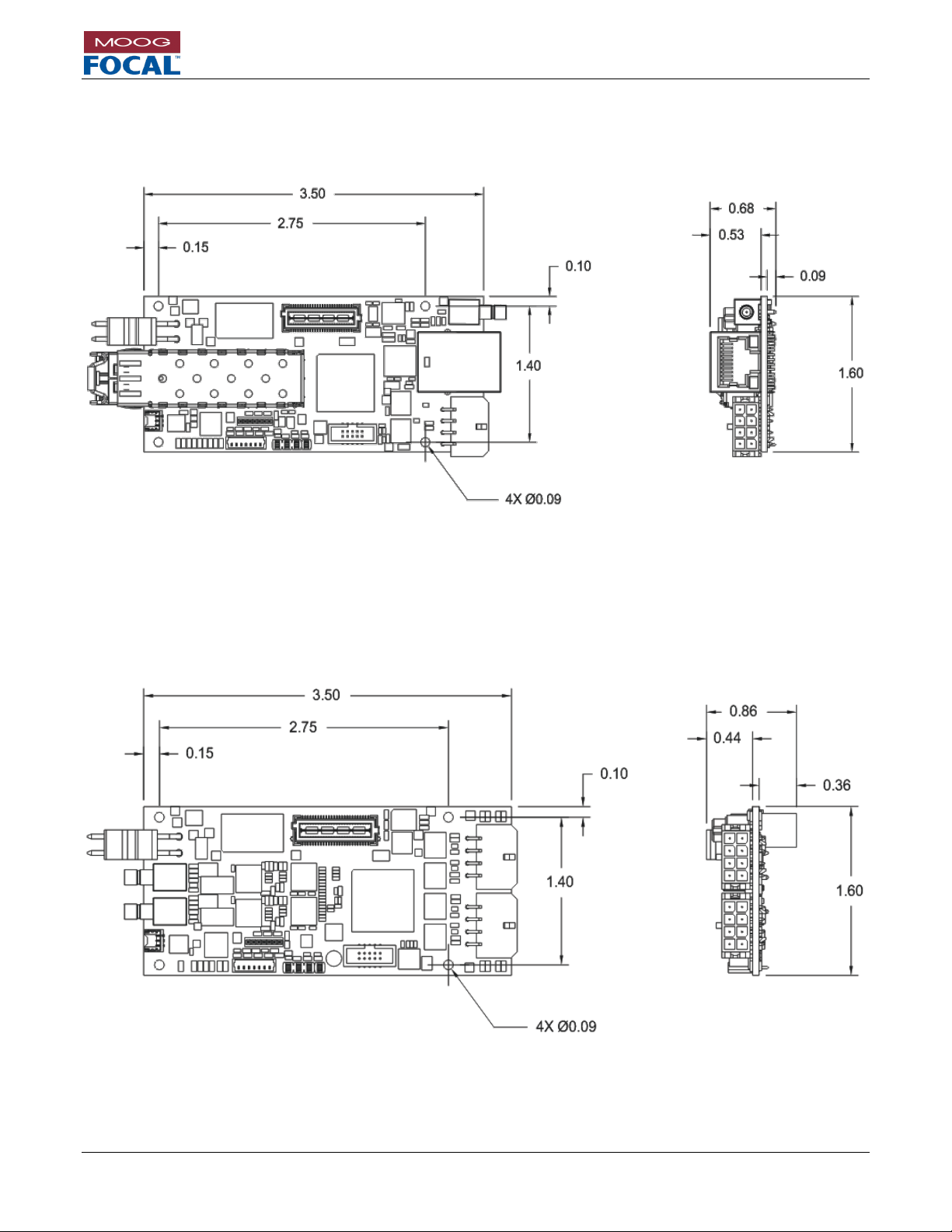
Model 914-X Series Modular Multiplexer System User Manual
Focal Technologies Corporation Page 10-8
A Moog Inc. Company Document Number: 914-0601-00 Rev. 5.0
10.9 914-X Series Dimensions
10.9.1 914-HDE
Figure 10-9: 914-HDE Dimensions (inches)
10.9.2 914-VDX
Figure 10-10: 914-VDX Dimensions (inches)
Page 86
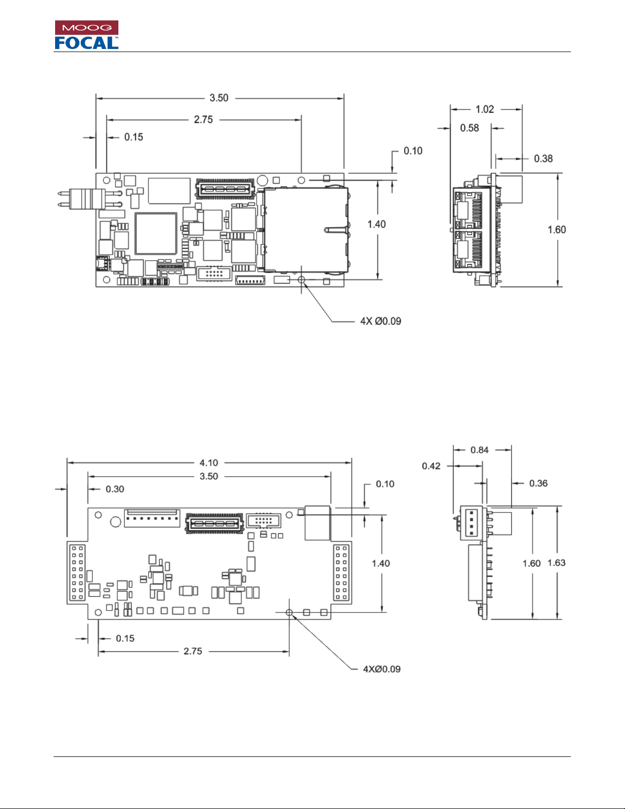
Model 914-X Series Modular Multiplexer System User Manual
Focal Technologies Corporation Page 10-9
A Moog Inc. Company Document Number: 914-0601-00 Rev. 5.0
10.9.3 914-EX.
Figure 10-11: 914-EX Dimensions (inches)
10.9.4 914-AX.
Figure 10-12: 914-AX Dimensions (inches)
Page 87
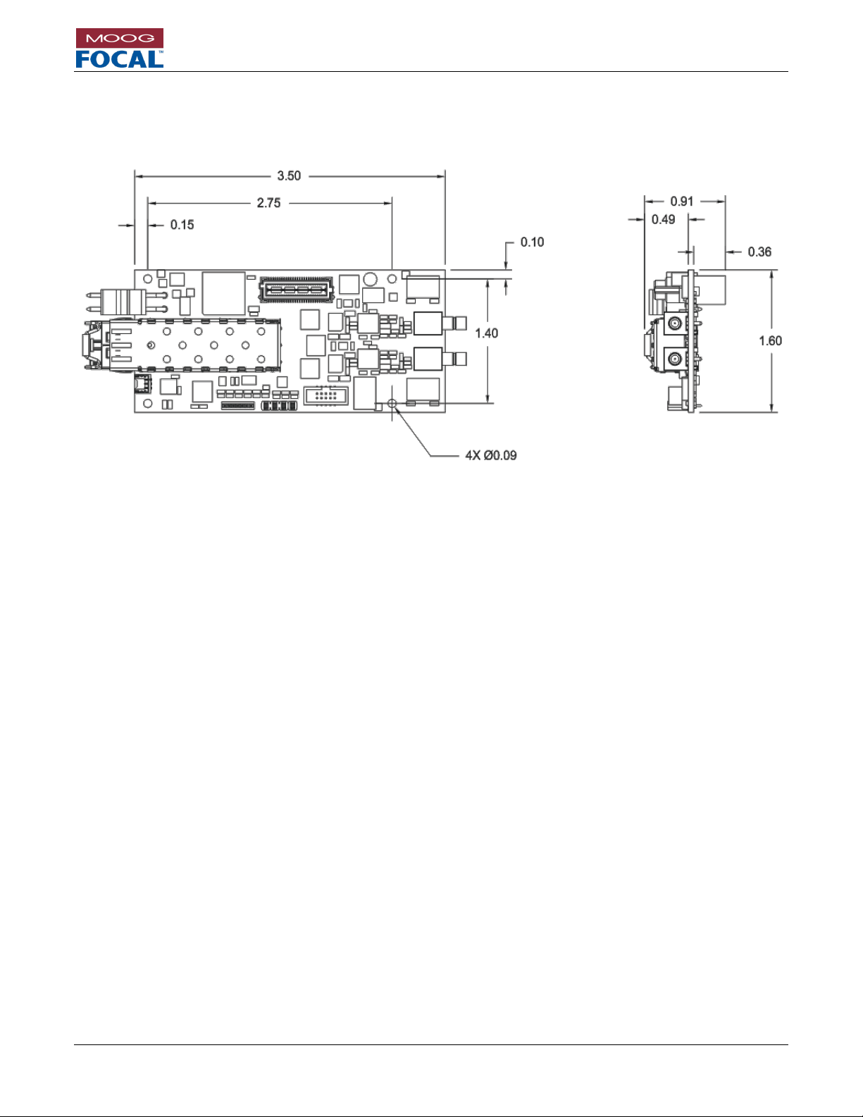
Model 914-X Series Modular Multiplexer System User Manual
Focal Technologies Corporation Page 10-10
A Moog Inc. Company Document Number: 914-0601-00 Rev. 5.0
10.9.5 914-HDV2
Figure 10-13: 914-HDV2 Dimensions (inches)
Page 88
Model 914-X Series Modular Multiplexer System User Manual
Focal Technologies Corporation Page 10-11
A Moog Inc. Company Document Number: 914-0601-00 Rev. 5.0
10.10 Connector Part Numbers
Table 10-3: Connector Part Numbers
Card
Type
Mfr.
Name
On-Board P/N
[Description]
Mating P/N
[Description]
914-HDE
Power
Molex
09-75-2024
[2-pin]
26-03-4020 [plug]
08-52-0113 [Crimps]
Video
Amphenol
142146-75
[SMB]
131-8403-101
[Cinch 75 ohm SMB plug, other SMB plugs will work,
RG179 cabling is recommended]
Ethernet
Wurth
Elektronik
7499110122
[RJ45]
Standard 8P8C RJ45 plug;
CAT5 or better cabling.
Serial Data
Molex
43045-0800
[8-pin Microfit]
0430250800 [plug]
0430300010 [crimps]
LED Header
FCI
20021521-00010T1LF
[10-pin; 2 row]
20021444-00010T1LF
[plug compatible with most 10 wire 0.05“ spacing
ribbon cables]
Diagnostics
Molex
0781710003
[3-pin]
0781720003
[3-pin plug]
914-VDX
Power
Molex
09-75-2024
[2-pin]
26-03-4020 [plug]
08-52-0113 [Crimps]
Video
Amphenol
142146-75
[SMB]
131-8403-101
[Cinch 75 ohm SMB plug, other SMB plugs will work,
RG179 cabling is recommended]
Serial Data
Molex
43045-0800
[8-pin Microfit]
0430250800 [plug]
0430300010 [crimps]
LED Header
FCI
20021521-00010T1LF
[10-pin; 2 row]
20021444-00010T1LF
[plug compatible with most 10 wire 0.05“ spacing
ribbon cables]
Diagnostics
Molex
0781710003
[3-pin]
0781720003
[3-pin plug]
914-EX
Power
Molex
09-75-2024
[2-pin]
26-03-4020 [plug]
08-52-0113 [Crimps]
Ethernet
Bel Fuse
0826-1X2T-23-F
[Dual RJ45 Array]
Standard 8P8C RJ45 plug;
CAT5 or better cabling.
LED Header
FCI
20021521-00010T1LF
[10-pin; 2 row]
20021444-00010T1LF
[plug compatible with most 10 wire 0.05“ spacing
ribbon cables]
Diagnostics
Molex
0781710003
[3-pin]
0781720003
[3-pin plug]
914-AX
Data
WAGO
733-364
[4-pin 2.5 mm]
733-104
[4-socket plug]
LED Header
FCI
20021521-00010T1LF
[10-pin; 2 row]
20021444-00010T1LF
[plug compatible with most 10 wire 0.05“ spacing
ribbon cables]
Diagnostics
Molex
0781710003
[3-pin]
0781720003
[3-pin plug]
914-HDV2
Power
Molex
09-75-2024
[2-pin]
26-03-4020 [plug]
08-52-0113 [Crimps]
Video
Amphenol
142146-75
[SMB]
131-8403-101
[Cinch 75 ohm SMB plug, other SMB plugs will work,
RG179 cabling is recommended]
LED Header
FCI
20021521-00010T1LF
[10-pin; 2 row]
20021444-00010T1LF
[plug compatible with most 10 wire 0.05“ spacing
ribbon cables]
Diagnostics
Molex
0781710003
[3-pin]
0781720003
[3-pin plug]
Page 89
Model 914-X Series Modular Multiplexer System User Manual
Focal Technologies Corporation Page 10-12
A Moog Inc. Company Document Number: 914-0601-00 Rev. 5.0
10.11 Signal Specifications
Table 10-4: Signal Specifications
Signal / Parameter
Min.
Typ.
Max.
Units
Diagnostics
RS-232
115
KBaud
Digital Video
SD/HD/3G-SDI
270
1485
2970
Mb/s
Latency* (914-HDE)
20
25
30
s
Latency* (914-HDV2)
1
s
Ethernet
Speed
10
100
1000
Mb/s
Latency* (914-HDE)
3**
6**
30**
s
Latency* (914-EX)
15**
12**
40**
s
Serial Data
RS-232 Data Rate
500
KBaud
RS-485/422 Termination
120
open
RS-485/422 Data Rate (914-HDE)
2500
KBaud
RS-485/422 Data Rate (914-VDX)
1250
KBaud
RS-485/422 Data Rate (914-DX)
500
KBaud
Latency* (914-HDE)
50
s
Latency* (914-VDX)
500
s
Latency* (914-DX)
500
s
Composite
Video
NTSC/PAL
Input Level
1 1.4
V
Output Level
1 1.4
V
Input / Output Impedance
75
Digital Resolution
10 bits
Signal to Noise Ratio
58 dB
Differential Gain
1.4 2 %
Differential Phase
0.6 1 Deg.
Luminance Nonlinearity
4.0
6.0
%
Latency*
500
s
AIB Plug-in
Modules
Latency*
50***
s
* Latency figures comprise end-to-end electronic latency. Fiber optic latency of 5 s/km is not included.
** Ethernet Latency is one frame time at the given Ethernet link speed plus the latency expressed in the table.
Minimum latency is for 1000BASE-T, typical for 100BASE-TX, and maximum for 10BASE-T.
***Does not include latency through the AIB plug-in modules. Specifications for the AIB plugin modules are
contained in the 700-0271-00 user guide.
Page 90

Model 914-X Series Modular Multiplexer System User Manual
Focal Technologies Corporation Page 11-1
A Moog Inc. Company Document Number: 914-0601-00 Rev. 5.0
11.0 Firmware Updates
If the factory has recommended a firmware update, these are the instructions to perform the update via
the diagnostic interface.
1. Receive both the 914-0401-01_FW_UPDATER_GUI_Release.7z installer and the new firmware
revision *.bin from Focal.
2. Decompress the 914-0401-01_FW_UPDATER_GUI_Release.7z file to the computer you plan to
use to update the 914 cards. If the file you received contains an ‘x’ in the file extension, remove
it.
3. Save the firmware *.bin file to the same computer
4. Connect the diagnostic port on the card to be updated to a COM port on the computer as per
section 3 of this manual:
a. J8 on the 914-HDE
b. J7 on the 914-VDX
c. J4 on the 914-EX
5. Ensure the card is powered OFF.
6. Run the “Model914FWUpdater.exe” application.
7. Select the COM port that is connected to RS232 Diagnostic of the 914 card.
8. Select the Model # to be updated (914-HDE, VDX, etc...).
9. Select “Clear Flash”.
10. Select the firmware *.bin file.
11. Press “Start FW Update”.
12. Power up the 914 card.
13. Wait for the update to complete (several minutes).
14. Power down the 914 card (it must be power cycled to take effect).
15. Repeat for all 914 cards that require an update, linked pairs must both have the same firmware
version.
Figure 11-1: Firmware Update GUI
Page 91

Model 914-X Series Modular Multiplexer System User Manual
Focal Technologies Corporation Page 11-2
A Moog Inc. Company Document Number: 914-0601-00 Rev. 5.0
11.1 Firmware Compatibility
Table 11-1 shows compatible revisions in rows. Each row is only compatible with other products and revisions in
that row.
Contact Moog Focal regarding non-standard updates of older products, or for compatible expansion cards for 914HDE Rev 2 cards.
Table 11-1: Firmware Revisions
Release Dates
914-HDE
Rev 2
914-HDE
Rev 3
914-VDX
914-EX
914-DX
2015/09
A0 - - - -
2015/11
A1 - - - -
2015/12
A2 - - - -
2016/03
B0 - - - -
2016/06
B1
C1 - -
-
2017/07
-
C2
A1 - -
2017/11
-
C3 - -
-
2018/05
-
C4
A2
A0
-
Page 92

Model 914-X Series Modular Multiplexer System User Manual
Focal Technologies Corporation Page 12-1
A Moog Inc. Company Document Number: 914-0601-00 Rev. 5.0
12.0 Feature Upgrades
If a feature upgrade has been purchased, these are the installation instructions. Feature upgrades allow 914-HDE
L1 cards to be upgraded to M1 version, as an example. Contact Focal for upgrade options for your cards.
1. Obtain Feature upgrade codes from Focal, there are 2 codes: Unlock Code and Feature Code. Both codes
are 16 digit hexadecimal alpha numeric numbers
2. Open the 914-HDE diagnostic GUI with the Console 914-HDE connected to a local COM port as per
manual section 3.
3. Use the “Tools” slide over menu on the left side, and select the “Configuration Tool”.
4. Enter both the Unlock and Feature Code, and select the destination card (remote or console), then press
“Apply”
5. Both remote and console cards can be upgraded from the console side, there is no need to directly access
the remote card, but it must be powered and have a valid optical link to receive the upgrade.
Figure 12-1: Feature Update Via Configuration Tool
Page 93

Model 914-X Series Modular Multiplexer System User Manual
Focal Technologies Corporation Page 13-1
A Moog Inc. Company Document Number: 914-0601-00 Rev. 5.0
13.0 Part Numbers
13.1 914-HDE Motherboard Part Numbers
914-HDE cards are typically specified in pairs of remote and console sides of the system. Pairs must have the same
version (L1, M1 or H1), and compatible (different) optical wavelengths. Single fiber bi-directional systems put the
lower wavelength (1310 or 1270 nm) at the remote, and the higher wavelength (1550 or 1330 nm) at the console.
CWDM wavelengths must be compatible with the chosen CWDM module, and must be unique between remote and
console cards, or from any other optical component in the system.
Table 13-1: 914-HDE Part Numbers
Part Number
Description
914-0023-13-CYZZ**
Remote Configuration, 1310 nm, SM, bidi single fiber, L1*** Version, 20dB
914-0023-XX*-CYZZ**
Remote Configuration, 1XX0 nm, SM, CWDM dual fiber, L1*** Version, 24 dB
914-0023-99-CYZZ**
Remote Configuration, No SFP, L1*** Version
914-0024-15-CYZZ**
Console Configuration, 1550 nm, SM, bidi single fiber, L1*** Version, 20 dB
914-0024-XX*-CYZZ**
Console Configuration, 1XX0 nm, SM, CWDM dual fiber, L1*** Version, 24 dB
914-0024-99-CYZZ**
Console Configuration, No SFP, L1*** Version
914-0026-13-CYZZ**
Remote Configuration, 1310 nm, SM, bidi single fiber, M1*** Version, 20 dB
914-0026-XX*-CYZZ**
Remote Configuration, 1XX0 nm, SM, CWDM dual fiber, M1*** Version, 24 dB
914-0026-99-CYZZ**
Remote Configuration, No SFP, M1*** Version
914-0027-15-CYZZ**
Console Configuration, 1550 nm, SM, bidi single fiber, M1*** Version, 20 dB
914-0027-XX*-CYZZ**
Console Configuration, 1XX0 nm, SM, CWDM dual fiber, M1*** Version, 24 dB
914-0027-99-CYZZ**
Console Configuration, No SFP, M1*** Version
914-0029-12-CYZZ**
Remote Configuration, 1270 nm, SM, bidi single fiber, H1*** Version, 20 dB
914-0029-XX*-CYZZ**
Remote Configuration, 1XX0 nm, SM, CWDM dual fiber, H1*** Version, 23 dB
914-0029-99-CYZZ**
Remote Configuration, No SFP, H1*** Version
914-0030-13-CYZZ**
Console Configuration, 1330 nm, SM, bidi single fiber, H1*** Version, 20 dB
914-0030-XX*-CYZZ**
Console Configuration, 1XX0 nm, SM, CWDM dual fiber, H1*** Version, 23 dB
914-0030-99-CYZZ**
Console Configuration, No SFP, H1*** Version
914-0037-13-CYZZ**
Remote Configuration, 1310 nm, SM, bidi single fiber, L1*** Version, 20 dB,
PT3K****
914-0037-XX*-CYZZ**
Remote Configuration, 1XX0 nm, SM, CWDM dual fiber, L1*** Version, 24 dB,
PT6K****
914-0038-13-CYZZ**
Remote Configuration, 1310 nm, SM, bidi single fiber, M1*** Version, 20 dB,
PT3K****
914-0038-XX*-CYZZ**
Remote Configuration, 1XX0 nm, SM, CWDM dual fiber, M1*** Version, 24 dB,
PT6K***
* Refer to Table 13-3
** Refer to Table 13-5
*** Refer to Table 13-4
Table 13-2: 914-HDE Included Accessories
Quantity
Description
1
Power harness, 6’, pigtailed
1
RS-232 Diagnostic cable, 6”, pigtailed
4
#2-56, 3/16”, 21/32” tall standoff
4
#2-56, 3/16”, 5/32” tall standoff
4
#2-56, hex nut
Page 94

Model 914-X Series Modular Multiplexer System User Manual
Focal Technologies Corporation Page 13-2
A Moog Inc. Company Document Number: 914-0601-00 Rev. 5.0
Table 13-3: 914-HDE CWDM Options
XX
Description
CWDM Band
Status
27
1271 nm optical transmitter
Blue
Special Order
29
1291 nm optical transmitter
Blue
Special Order
31
1311 nm optical transmitter
Blue
Special Order
33
1331 nm optical transmitter
Blue
Special Order
35
1351 nm optical transmitter
Blue
Special Order
37
1371 nm optical transmitter
Blue
Special Order
39
1391 nm optical transmitter
Blue
Special Order
41
1411 nm optical transmitter
Blue
Special Order
43
1431 nm optical transmitter
Blue
Special Order, Not recommended
45
1451 nm optical transmitter
Blue
Special Order, Not recommended
47
1471 nm optical transmitter
Red
Recommended, compatible with 914-CWDM
49
1491 nm optical transmitter
Red
Recommended, compatible with 914-CWDM
51
1511 nm optical transmitter
Red
Recommended
53
1531 nm optical transmitter
Red
Recommended
55
1551 nm optical transmitter
Red
Upgrade
57
1571 nm optical transmitter
Red
Upgrade
59
1591 nm optical transmitter
Red
Upgrade, not for use with Moog Focal OMS
61
1611 nm optical transmitter
Red
Upgrade, not for use with Moog Focal OMS
Red wavelengths are recommended, particularly 1471 to 1571 nm.
1591 and 1611 nm wavelengths are not recommended for use with the Moog Focal Optical Monitoring
System (OMS).
When configuring a system, it is best to choose adjacent wavelengths and not to mix red band with blue
band wavelengths.
Table 13-4: 914-HDE Factory Versions
Feature
Parameter
L1
M1
H1
Video
Speed
HD/SD
3G/HS/SD
3G/HD/SD
Ethernet
Speed (Mb/s)
10/100/1000*
10/100/1000**
10/100/1000
Serial Ch1
Format
RS232, RS485, RS422
Serial Ch2
Format
RS232, RS485, RS422
LS Expansion
Channels
Quantity
4
MS Expansion
Channels
Quantity 0 4***
4***
Optical Bandwidth
Gb/s
1.8
3.5
5.6
* L1 Version Supports HD-SDI or 1000 BASE-T, default is to support HD-SDI. This can be changed via the 914HDE Diagnostic GUI
** M1 Version supports 3G-SDI or 1000 BASE-T. When 3G-SDI is plugged, Ethernet is limited to 300Mb/s
bandwidth.
*** Limited to available optical bandwidth. Refer to Section 3.3.
Page 95

Model 914-X Series Modular Multiplexer System User Manual
Focal Technologies Corporation Page 13-3
A Moog Inc. Company Document Number: 914-0601-00 Rev. 5.0
Table 13-5: 914-HDE Factory Configurations
Setting Option
Video Setting
Ethernet Setting
Serial Channel 1
Setting
Serial Channel 2
Setting
BLANK
(Default)
Enabled*
Auto-Negotiate**
RS232
C001
Enabled*
Auto-Negotiate**
RS485
C002
Enabled*
Auto-Negotiate**
RS422
C003
Enabled*
Auto-Negotiate**
RS232
RS485
C004
Enabled*
Auto-Negotiate**
RS232
RS422
C005
Enabled*
Auto-Negotiate**
RS485
RS422
C010
Enabled*
100 BASE-TX
Full Duplex Only
RS232
C011
Enabled*
100 BASE-TX
Full Duplex Only
RS485
C012
Enabled*
100 BASE-TX
Full Duplex Only
RS422
C013
Enabled*
100 BASE-TX
Full Duplex Only
RS232
RS485
C014
Enabled*
100 BASE-TX
Full Duplex Only
RS232
RS422
C015
Enabled*
100 BASE-TX
Full Duplex Only
RS485
RS422
C020
L1 Version Only
SD-SDI Only
Auto-Negotiate up to
1000 BASE-T
RS232
C021
L1 Version Only
SD-SDI Only
Auto-Negotiate up to
1000 BASE-T
RS485
C022
L1 Version Only
SD-SDI Only
Auto-Negotiate up to
1000 BASE-T
RS422
C023
L1 Version Only
SD-SDI Only
Auto-Negotiate up to
1000 BASE-T
RS232
RS485
C024
L1 Version Only
SD-SDI Only
Auto-Negotiate up to
1000 BASE-T
RS232
RS422
C025
L1 Version Only
SD-SDI Only
Auto-Negotiate up to
1000 BASE-T
RS485
RS422
* HD/SD-SDI enabled for L1 version, 3G/HD/SD-SDI enabled for M1/H1 versions.
** 10/100 BASE-T(X) default for L1 version, 10/100/1000 BASE-T(X) for M1/H1 versions.
Notes:
1. Factory configuration options represent “as shipped” settings.
2. Users may alter all allowable configurations via 914-HDE Diagnostic GUI based on 914-HDE version: L1,
M1 or H1.
3. Default configuration is recommended for spare assemblies.
4. Other factory settings are possible, contact Moog Focal for more options.
5. Configurations other than the default are subject to a surcharge.
Page 96
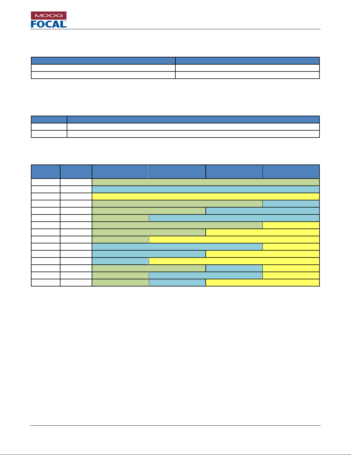
Model 914-X Series Modular Multiplexer System User Manual
Focal Technologies Corporation Page 13-4
A Moog Inc. Company Document Number: 914-0601-00 Rev. 5.0
13.2 914-VDX Part Numbers
Table 13-6: 914-VDX Part Numbers
Part Number
Description
914-0039-00-CYZZ*
Standard 914-VDX
914-0039-01-CYZZ*
914-VDX PT6K**
* Refer to Table 13-8
** PT6K refers to Pressure Tolerant Assembly rated to 6000 PSI
Table 13-7: 914-VDX Included Accessories
Quantity
Description
1
RS-232 Diagnostic cable, 6”, pigtailed
4
#2-56, 3/16”, 21/32” tall standoff
Table 13-8: 914-VDX Factory Configuration Options
Remote
Console
Serial Channel 1
Setting
Serial Channel 2
Setting
Serial Channel 3
Setting
Serial Channel 4
Setting
Blank
C100
RS232
C001
C101
RS485*
C002
C102
RS422**
C003
C103
RS232
RS485*
C004
C104
RS232
RS485*
C005
C105
RS232
RS485*
C006
C106
RS232
RS422**
C007
C107
RS232
RS422**
C008
C108
RS232
RS422**
C009
C109
RS485*
RS422**
C010
C110
RS485*
RS422**
C011
C111
RS485*
RS422**
C012
C112
RS232
RS485*
RS422**
C013
C113
RS232
RS485*
RS422**
C014
C114
RS232
RS485*
RS422**
* RS485 has differential 120 ohm terminations enabled with a timeout of 1 ms
** RS422 has differential terminations enabled
Notes:
1. Factory configuration options represent “as shipped” settings.
2. Users may alter all configurations via 914-HDE Diagnostic GUI in combination with DIP switches.
3. Default configuration is recommended for spare assemblies
4. SW1 is always set to [OFF, OFF] for expansion channel 1. Ensure systems with multiple expansion cards
have unique channel settings.
5. Other factory settings are possible, contact Moog Focal for more options.
6. Configurations other than the default are subject to a surcharge.
Page 97

Model 914-X Series Modular Multiplexer System User Manual
Focal Technologies Corporation Page 13-5
A Moog Inc. Company Document Number: 914-0601-00 Rev. 5.0
13.3 914-EX Part Numbers
Table 13-9: 914-EX Part Numbers
Part Number
Description
914-0040-00-CYZZ*
Standard 914-EX
914-0040-01-CYZZ*
914-EX PT6K**
* Refer to Table 13-11
** PT6K refers to Pressure Tolerant Assembly rated to 6000 PSI
Table 13-10: 914-EX Included Accessories
Quantity
Description
1
RS-232 Diagnostic cable, 6”, pigtailed
4
#2-56, 3/16”, 21/32” tall standoff
Table 13-11: 914-EX Factory Configuration Options
Remote
Console
Ethernet Port 1 Setting
Ethernet Port 2 Setting
Link Fault
Passthrough
Blank
C100
10/100/1000 BASE-T(X)
Disabled
C001
C101
10/100/1000 BASE-T(X)
100 BASE-TX
C002
C102
10/100/1000 BASE-T(X)
10 BASE-T
C003
C103
100 BASE-TX
C004
C104
100 BASE-TX
10 BASE-T
C005
C105
10 BASE-T
C010
C110
10/100/1000 BASE-T(X)
Enabled
C011
C111
10/100/1000 BASE-T(X)
100 BASE-TX
C012
C112
10/100/1000 BASE-T(X)
10 BASE-T
C013
C113
100 BASE-TX
C014
C114
100 BASE-TX
10 BASE-T
C015
C115
10 BASE-T
Notes:
1. Factory configuration options represent “as shipped” settings.
2. Users may alter all configurations via 914-HDE Diagnostic GUI in combination with DIP switches.
3. Default configuration is recommended for spare assemblies
4. SW1 is always set to [OFF, OFF] for expansion channel 1. Ensure systems with multiple expansion cards
have unique channel settings.
5. Other factory settings are possible, contact Moog Focal for more options.
6. Configurations other than the default are subject to a surcharge.
Page 98
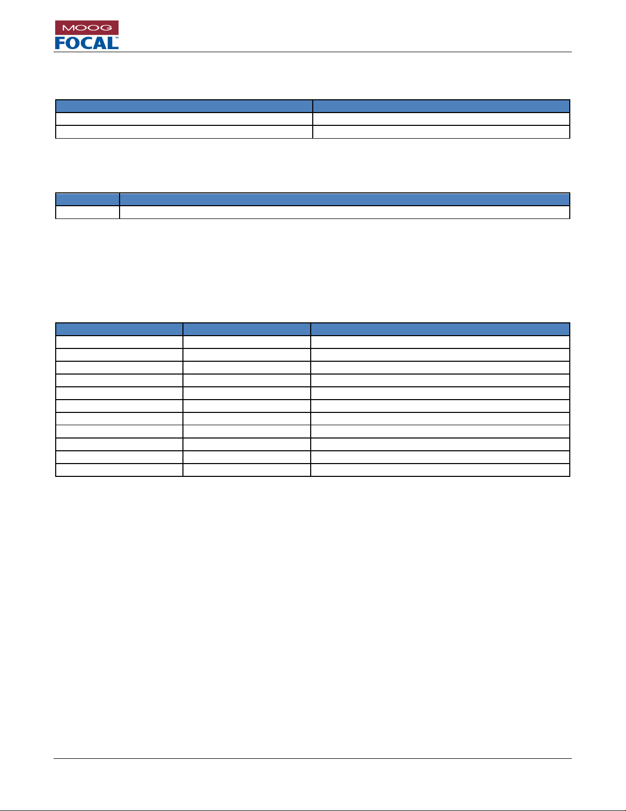
Model 914-X Series Modular Multiplexer System User Manual
Focal Technologies Corporation Page 13-6
A Moog Inc. Company Document Number: 914-0601-00 Rev. 5.0
13.4 914-AX Part Numbers
Table 13-12: 914-AX Part Numbers
Part Number
Description
914-0041-00
Standard 914-AX
914-0041-01
914-AX PT6K*
* PT6K refers to Pressure Tolerant Assembly rated to 6000 PSI
Table 13-13: 914-AX Included Accessories
Quantity
Description
4
#2-56, 3/16”, 21/32” tall standoff
13.5 AIB Module Part Numbers
Please refer to 700-0271-00 AIB Plug-In Modules User Guide for module details and configuration.
Table 13-14: AIB Module Part Numbers
Part Number
Card ID
Description
903-0251-00
AIB 232
RS232 Interface
903-0251-01
AIB TRIG
Modified RS232 for +5 to +25 V for trigger signals.
903-0252-00
AIB 485/422
RS485/RS422 Interface
903-0252-01
AIB TTL
TTL Interface, 0 to +5 V TTL signals
903-0261-00
AIB-ARCNET
Tritech ARCNET compatible interface
903-0244-00
AIB-HYDRO
Default hydrophone gain of 36 dB
903-0244-01
AIB-IRIG
Modified for IRIG-B
903-0244-02
AIB-HYDRO
Provides 12 V to the hydrophone, gain is bypassed
903-0250-00
AIB-MS900
MS900 Analog Sonar Interface
903-0250-01
AIB-MS900L
MS900 Analog Sonar Low Frequency Interface
903-0297-00
AIB-CANBUS
CAN bus interface, up to 1 Mb/s supported
Page 99
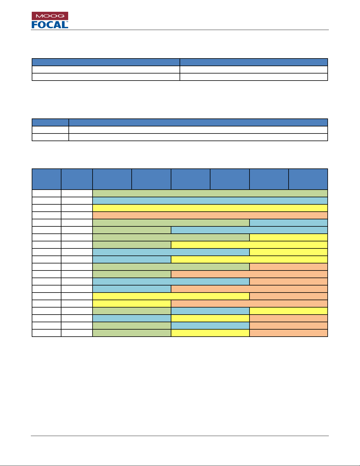
Model 914-X Series Modular Multiplexer System User Manual
Focal Technologies Corporation Page 13-7
A Moog Inc. Company Document Number: 914-0601-00 Rev. 5.0
13.6 914-DX Part Numbers (Preliminary)
Table 13-15: 914-DX Part Numbers
Part Number
Description
914-0042-00-CYZZ*
Standard 914-DX
914-0042-01-CYZZ*
914-DX PT6K**
* Refer to Table 13-17
** PT6K refers to Pressure Tolerant Assembly rated to 6000 PSI
Table 13-16: 914-DX Included Accessories
Quantity
Description
1
RS-232 Diagnostic cable, 6”, pigtailed
4
#2-56, 3/16”, 21/32” tall standoff
Table 13-17: 914-DX Factory Configuration Options
Remote
Console
Serial
Channel 1
Setting
Serial
Channel 2
Setting
Serial
Channel 3
Setting
Serial
Channel 4
Setting
Serial
Channel 5
Setting
Serial
Channel 6
Setting
Blank
C100
RS232
C001
C101
RS485*
C002
C102
RS422**
C003
C103
TTL
C004
C104
RS232
RS485*
C005
C105
RS232
RS485*
C006
C106
RS232
RS422**
C007
C107
RS232
RS422**
C008
C108
RS485*
RS422**
C009
C109
RS485*
RS422**
C010
C110
RS232
TTL
C011
C111
RS232
TTL
C012
C112
RS485*
TTL
C013
C113
RS485*
TTL
C014
C114
RS422**
TTL
C015
C115
RS422**
TTL
C016
C116
RS232
RS485*
RS422**
C017
C117
RS485*
RS422**
TTL
C018
C118
RS232
RS485*
TTL
C019
C119
RS232
RS422**
TTL
* RS485 has 120 ohm differential terminations enabled with a timeout of 1 ms
** RS422 has 120 ohm differential terminations enabled
Notes:
1. Factory configuration options represent “as shipped” settings.
2. Users may alter all configurations via 914-HDE Diagnostic GUI in combination with DIP switches.
3. Default configuration is recommended for spare assemblies
4. SW1 is always set to [OFF, OFF] for LS expansion channel 1. Ensure systems with multiple LS expansion
cards have unique channel settings.
5. Other factory settings are possible, contact Moog Focal for more options.
6. Configurations other than the default are subject to a surcharge.
Page 100

Model 914-X Series Modular Multiplexer System User Manual
Focal Technologies Corporation Page 13-8
A Moog Inc. Company Document Number: 914-0601-00 Rev. 5.0
13.7 914-HDV2 Part Numbers
Table 13-18: 914-HDV2 Part Numbers
Part Number
Description
Status
Dual Channel Options
914-0031-00
HDV2 Console non-MSA dual video output; 1260 nm to 1620 nm optical
inputs
Recommended
914-0032-00
HDV2 Remote non-MSA dual video input; CWDM output wavelengths:
Ch1 1271 nm and Ch2 1291 nm
Special Order
914-0032-01
HDV2 Remote non-MSA dual video input; CWDM output wavelengths:
Ch1 1311 nm and Ch2 1331 nm
Special Order
914-0032-02
HDV2 Remote non-MSA dual video input; CWDM output wavelengths:
Ch1 1351 nm and Ch2 1371 nm
Special Order
914-0032-03
HDV2 Remote non-MSA dual video input; CWDM output wavelengths:
Ch1 1391 nm and Ch2 1411 nm
Special Order
914-0032-04
HDV2 Remote non-MSA dual video input; CWDM output wavelengths:
Ch1 1471 nm and Ch2 1491 nm; Recommended for use with 914CWDM
Recommended
914-0032-05
HDV2 Remote non-MSA dual video input; CWDM output wavelengths:
Ch1 1511 nm and Ch2 1531 nm
Recommended
914-0032-06
HDV2 Remote non-MSA dual video input; CWDM output wavelengths:
Ch1 1551 nm and Ch2 1571 nm
Recommended
914-0032-07
HDV2 Remote non-MSA dual video input; CWDM output wavelengths:
Ch1 1591 nm and Ch2 1611 nm
Recommended***
Single Channel Options
914-0033-00
HDV2 Console MSA single video output; 1260 nm to 1620 nm optical
input
Recommended
914-0034-XX*
HDV2 Remote MSA single video input; CWDM output wavelength:
Ch1 1XX1 nm
See
Table 13-20
914-0035-XX*
HDV2 Remote MSA single video input; CWDM output wavelength:
Ch1 1XX1 nm PT6K**
See
Table 13-20
* XX Refer to Table 13-20
** PT6K refers to Pressure Tolerant Assembly rated to 6000 PSI
*** Not for use with Moog Focal OMS (Optical Monitoring System)
 Loading...