

Montana GRILL 6 Owner's Manual
MONTANA GRILL 6 BURNER GAS BARBEQUE - OWNERS MANUAL
Retain manual for future reference
GA
SQO
S
Parts list
Setting up the Barbeque
Assembly instructions
Safety
Leak Test
Igniting
Cooking
Before the first use
Grilling
Roasting
2
3
4
10
11
12
12
12
12
12
Teppanyaki
Wok
Cleaning
Regular cleaning
Maintenance
Checks & repairs
Trouble shooting
Warranty
Contact
12
12
12
12
13
13
13
14
14
1.
INDEX
MONTANA GRILL 6 BURNER GAS BARBEQUE - OWNERS MANUAL
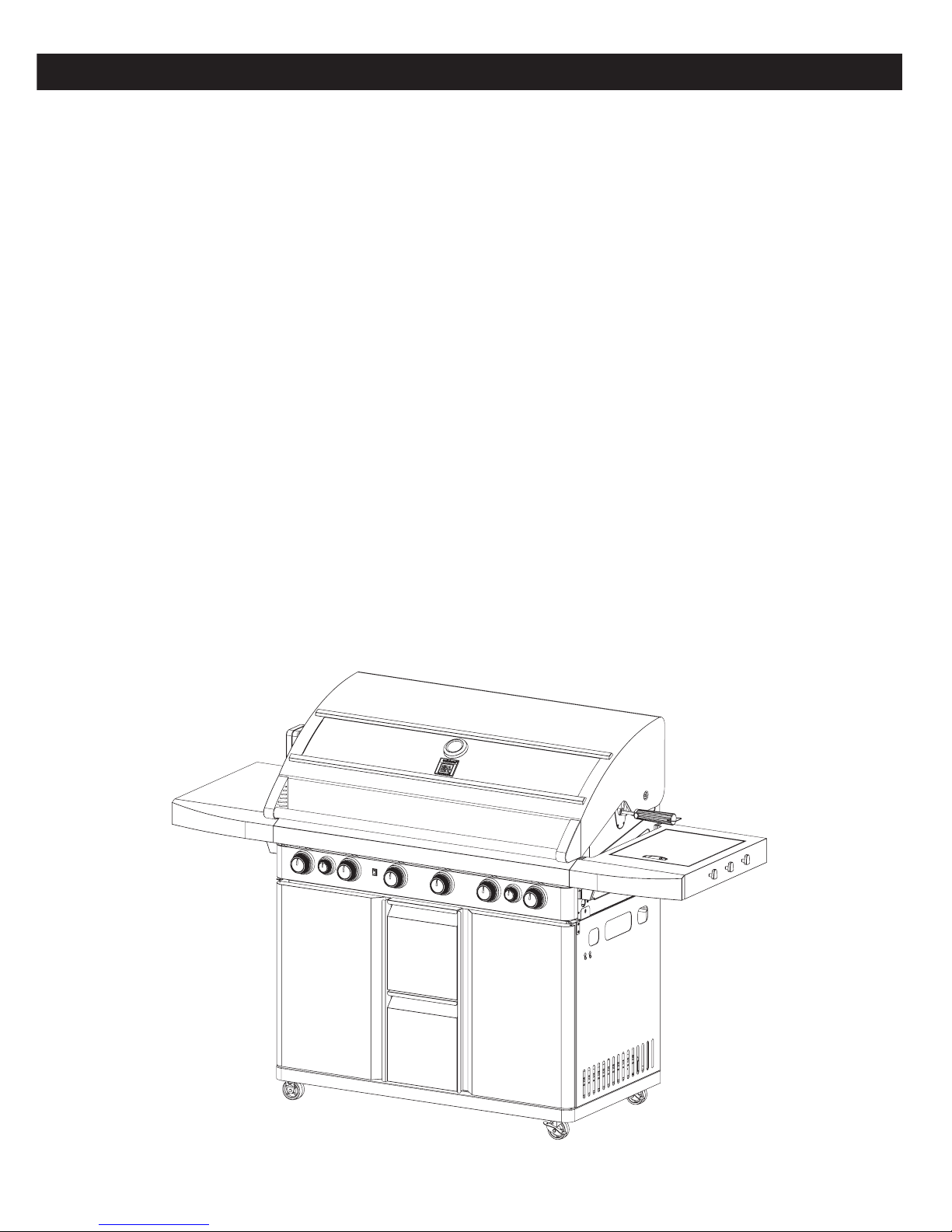
We’d like to thank you for choosing a Montana Grill gas barbeque. We believe that our barbeque will provide you
with the many years of reliable service that you have come to expect of anything with the Montana Grill name on it.
Please take the time to read these instructions thoroughly before use. These will not only help you get the most from
your new barbeque, but will ensure that you use the barbeque safely. If you have any questions or suggestions,
please contact us. You will find details in the back of this manual.
2.
1
2
2
RIGID CASTER
3
2
SWIVEL CASTER
4
1
5
1
CART LEFT PANEL WELD
6
1
CART RIGHT PANEL WELD
7
1
CART REAR PANEL
1
GAS TANK TRAY
9
10
2
DRAWER
11
1
DOOR UPPER
12
2
DOOR ASSEMBLY
13
1
BODY & LID ASSEMBLY
14
1
LEFT SHELF ASSEMBLY
15
1
RIGHT SHELF ASSEMBLY
16
2
SIDE SPACER FRONT
17
2
SIDE SPACER REAR
18
1
SIDE GRILL
19
1
SIDE BURNER & DISH
20
1
WARMING RACK
21
1
COOKING GRID
22
1
COOKING PAN
CART BOTTOM
STRENGTHEN WELD
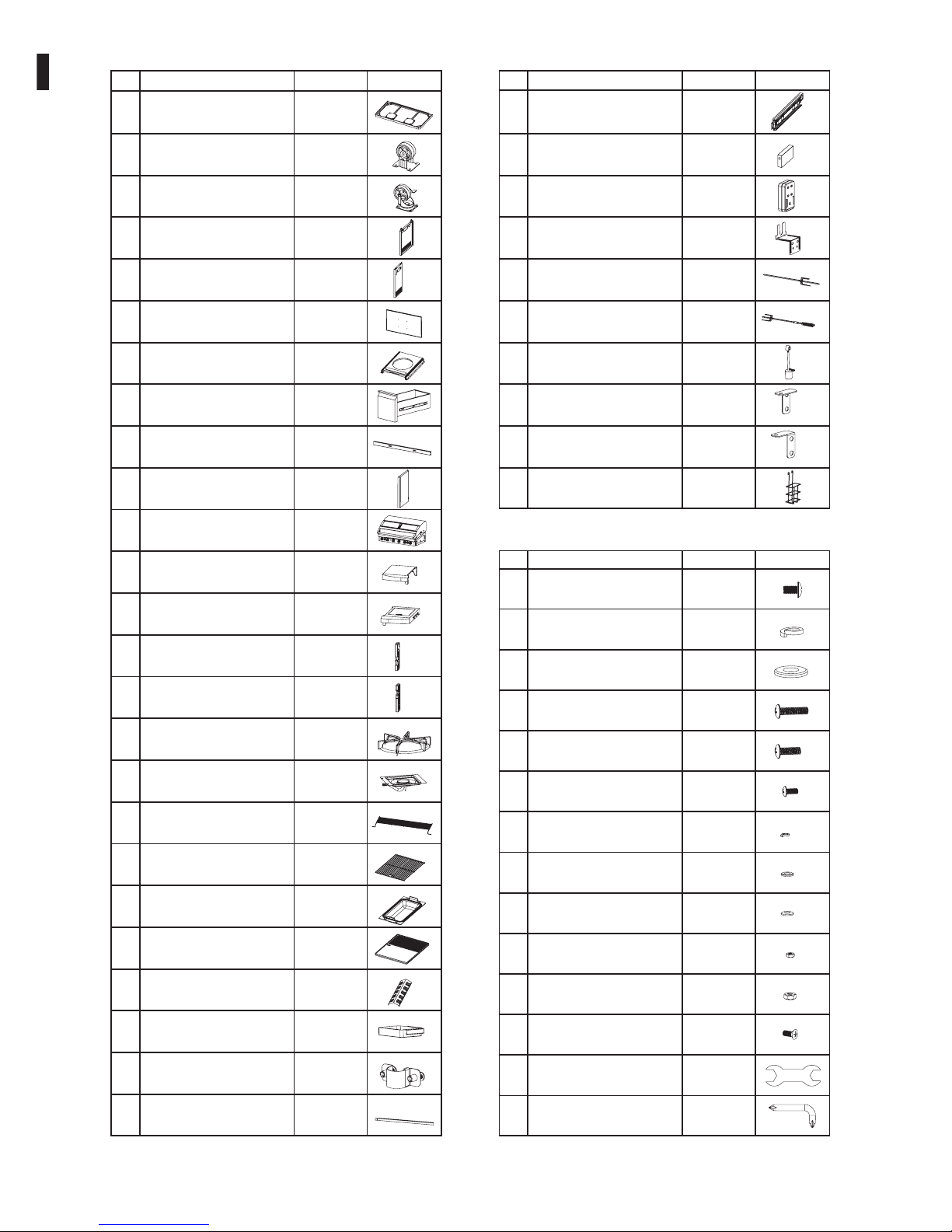
ITEM DESCRIPTION QUANTITY PICTURE
1
MOTOR
1
MOTOR SUPPORT
1
FORK A
1
FORK B
1
CLUMP WEIGHT
1
DOOR AXIS SUPPORT-L
1
DOOR AXIS SUPPORT-R
1
BATTERY HOLDER
23
24
25
26
1
COOKING PLATE
2
HEAT PANEL
1
1
OIL CUP
FLEXIBLE GAS HOSE
FIXED
2
DRAWER VERTICAL
SUPPORT
DRAWER HORIZONTAL
SUPPORT
ITEM DESCRIPTION QUANTITY PICTURE
1
STORE BATTERY
4
28
29
30
31
32
33
34
35
36
27
A
B
54
48
M6 SPRING WASHER
C
54
M6 FLAT WASHER
D
4
M6X45MM PHILIPS
HEAD SCREW
E
8
M6X30MM PHILIPS
HEAD SCREW
F
4
M4X10MM PHILIPS
HEAD SCREW
G
4
M4 SPRING WASHER
H
4
I
4
M4 FLAT WASHER
M4 MICA WASHER
J
4
M4 NUT
M6*16MM COUNTERSUNK
HEAD SCREW
N
4
1
1
M
2
M6 NUT
SPANNER
SCREWDRIVER
M6X12MM PHILIPS
HEAD SCREW
ITEM DESCRIPTION QUANTITY PICTURE
PARTS LIST PARTS LIST
FASTENERS
2.
1
2
2
RIGID CASTER
3
2
SWIVEL CASTER
4
1
5
1
CART LEFT PANEL WELD
6
1
CART RIGHT PANEL WELD
7
1
CART REAR PANEL
1
GAS TANK TRAY
9
10
2
DRAWER
11
1
DOOR UPPER
12
2
DOOR ASSEMBLY
13
1
BODY & LID ASSEMBLY
14
1
LEFT SHELF ASSEMBLY
15
1
RIGHT SHELF ASSEMBLY
16
2
SIDE SPACER FRONT
17
2
SIDE SPACER REAR
18
1
SIDE GRILL
19
1
SIDE BURNER & DISH
20
1
WARMING RACK
21
1
COOKING GRID
22
1
COOKING PAN
CART BOTTOM
STRENGTHEN WELD
ITEM DESCRIPTION QUANTITY PICTURE
1
MOTOR
1
MOTOR SUPPORT
1
FORK A
1
FORK B
1
CLUMP WEIGHT
1
DOOR AXIS SUPPORT-L
1
DOOR AXIS SUPPORT-R
1
BATTERY HOLDER
23
24
25
26
1
COOKING PLATE
2
HEAT PANEL
1
1
OIL CUP
FLEXIBLE GAS HOSE
FIXED
2
DRAWER VERTICAL
SUPPORT
DRAWER HORIZONTAL
SUPPORT
ITEM DESCRIPTION QUANTITY PICTURE
1
STORE BATTERY
4
28
29
30
31
32
33
34
35
36
27
A
B
54
48
M6 SPRING WASHER
C
54
M6 FLAT WASHER
D
4
M6X45MM PHILIPS
HEAD SCREW
E
8
M6X30MM PHILIPS
HEAD SCREW
F
4
M4X10MM PHILIPS
HEAD SCREW
G
4
M4 SPRING WASHER
H
4
I
4
M4 FLAT WASHER
M4 MICA WASHER
J
4
M4 NUT
M6*16MM COUNTERSUNK
HEAD SCREW
N
4
1
1
M2M6 NUT
SPANNER
SCREWDRIVER
M6X12MM PHILIPS
HEAD SCREW
ITEM DESCRIPTION QUANTITY PICTURE
PARTS LIST PARTS LIST
FASTENERS
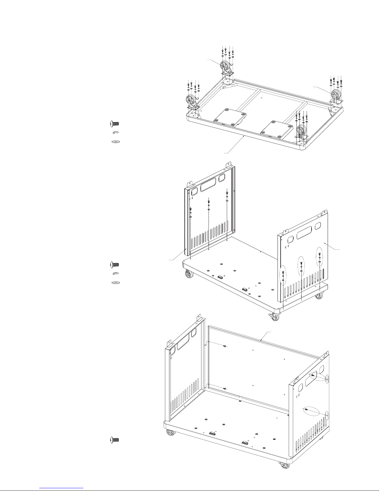
STEP 1
ATTACH CASTERS
1
2
3
6
4
5
4.
1. Turn Cart Bottom Plate Assembly (1) upside down.
2. Align each caster on each of the cart bottom caster plates, as shown in diagram.
3. Thread 4xBolt (A) first with Spring Washer (B) and then Flat Washer (C).
4. Screw through the caster hole into the cart bottom caster plates.
5. Repeat for each caster making sure Rigid Casters (2) are on the left-hand
side and the Swivel Castors (3) are on the right-hand side of the cabinet.
A M6X12...16 PCS
B M6 SPRING WASHER...16 PCS
C M6 FLAT WASHER...16 PCS
A M6X12...6 PCS
B M6 SPRING WASHER...6 PCS
C M6 FLAT WASHER...6 PCS
1. Both rounded corners of Cart Bottom Plate Assembly (1) should be
facing the front of cabinet as shown in diagram.
2. Align the Cart Left Panel (4) pre-drilled holes to Cart Bottom
Plate Assembly (1).
3. Thread 3xBolt (A) first with Spring Washer (B) and then Flat Washer (C).
4. Screw through Cart Left Panel (4) into Cart Bottom Panel
Plate Assembly (1).
5. Repeat for Cart Right Panel (5).
A M6X12...4 PCS
1. Partially loosen pre-installed bolts located at back
Cart Bottom Plate Assembly (1).
2. Place Cart Rear Panel (6) between left and right panels
aligning with pre-drilled holes.
3. Thread 4xBolts (A).
4. Screw 2xBolt (A) through left-hand side of Cart Rear Panel (6)
pre-drilled holes into Cart Left Panel (4), as shown in diagram.
5. Repeat for right-hand side of Cart Rear Panel.
ASSEMBLY & INSTALLATION
PLEASE ENSURE THAT YOU HAVE ALL PARTS AND FASTENERS BEFORE BEGINNING ASSEMBLY.
STEP 2
ATTACH LEFT AND RIGHT PANELS
STEP 3
ATTACH CART REAR PANEL
3.
SETTING UP THE BARBEQUE
1. POSITIONING
Please make sure that the barbeque is NOT positioned underneath any combustible material or surface.
There MUST be a clearance of at least 250mm from the sides of the Barbeque to any combustible materials or surfaces. There must also be a clearance of at least
1500mm above the cooking surfaces to any combustible surface, and 500mm clearance at the back.
Flammable materials of any description MUST be kept well away from the barbeque.
The barbeque must be positioned such that the gas cylinder is kept away from direct sunlight.
The barbeque must be positioned to avoid walkways, gangways and general pedestrian access.
The nature of a barbeque is such that many of the surfaces are hot to touch, the positioning of the barbeque should take into consideration the possibility of
accidental hand or body contact.
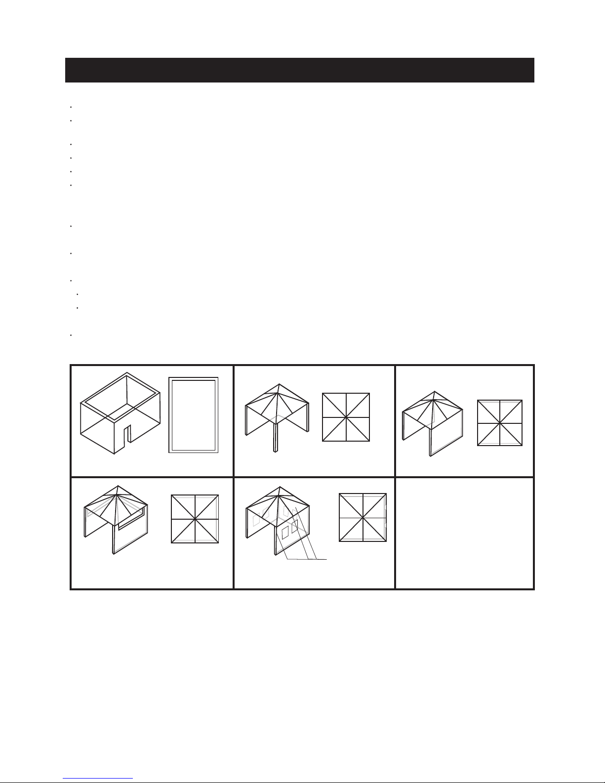
Any enclosure in which the appliance is used shall comply with one of the following:
An enclosure with walls on all sides, but at least one permanent opening at ground level and no overhead cover.
SEE EXAMPLE 1
Within a partial enclosure that includes an overhead cover and no more than two walls.
SEE EXAMPLE 2 & 3
Within a partial enclosure that includes an overhead cover and more than two walls, the following shall apply -
at least 25% of the total wall area is completely open; and
at least 30% of the remaining wall area is open and unrestricted
SEE EXAMPLE 4 & 5
In the case of balconies, at least 20% of the total of the side, back and front wall areas shall be and remain open and unrestricted.
EXAMPLE 1
EXAMPLE 4
30% or more in total
of the remaining wall
area in open is unrestricted
Open side at least 25% of
total wall area
EXAMPLE 5
Open side at least 25% of
total wall area
30% or more in total
of the remaining wall
area in open is unrestricted
EXAMPLE 3
EXAMPLE 2
THIS APPLIANCE SHALL ONLY BE USED IN AN ABOVE GROUND OPEN AIR SITUATION WITH NATURAL VENTILATION, WITHOUT STAGNANT AREAS, WHERE
GAS LEAKAGE AND PRODUCTS OF COMBUSTION ARE RAPIDLY DISPERSED BY WIND AND NATURAL CONVECTION.
STEP 1
ATTACH CASTERS
1
2
3
6
4
5
4.
1. Turn Cart Bottom Plate Assembly (1) upside down.
2. Align each caster on each of the cart bottom caster plates, as shown in diagram.
3. Thread 4xBolt (A) first with Spring Washer (B) and then Flat Washer (C).
4. Screw through the caster hole into the cart bottom caster plates.
5. Repeat for each caster making sure Rigid Casters (2) are on the left-hand
side and the Swivel Castors (3) are on the right-hand side of the cabinet.
A M6X12...16 PCS
B M6 SPRING WASHER...16 PCS
C M6 FLAT WASHER...16 PCS
A M6X12...6 PCS
B M6 SPRING WASHER...6 PCS
C M6 FLAT WASHER...6 PCS
1. Both rounded corners of Cart Bottom Plate Assembly (1) should be
facing the front of cabinet as shown in diagram.
2. Align the Cart Left Panel (4) pre-drilled holes to Cart Bottom
Plate Assembly (1).
3. Thread 3xBolt (A) first with Spring Washer (B) and then Flat Washer (C).
4. Screw through Cart Left Panel (4) into Cart Bottom Panel
Plate Assembly (1).
5. Repeat for Cart Right Panel (5).
A M6X12...4 PCS
1. Partially loosen pre-installed bolts located at back
Cart Bottom Plate Assembly (1).
2. Place Cart Rear Panel (6) between left and right panels
aligning with pre-drilled holes.
3. Thread 4xBolts (A).
4. Screw 2xBolt (A) through left-hand side of Cart Rear Panel (6)
pre-drilled holes into Cart Left Panel (4), as shown in diagram.
5. Repeat for right-hand side of Cart Rear Panel.
ASSEMBLY & INSTALLATION
PLEASE ENSURE THAT YOU HAVE ALL PARTS AND FASTENERS BEFORE BEGINNING ASSEMBLY.
STEP 2
ATTACH LEFT AND RIGHT PANELS
STEP 3
ATTACH CART REAR PANEL
 Loading...