

Page 1

Instruction Manual
for
Monroe Electronics, Inc.
Isoprobe® Electrostatic Voltmeter
Model 244A
Specifications subject to change without notice.
P/N 0340074
053013
100 Housel Ave PO Box 535 Lyndonville NY 14098 Fax: 585-765-9330 monroe-electronics.com
114
Page 2

TABLE OF CONTENTS
1.
2. BEWARE: HIGH VOLTAGE ........................................ PAGE 4
3.
4.
5. CONTROLS AND INDICATORS ................................. PAGE 10
6.
7.
APPENDIXES:
MODEL 1017 PROBE MOUNTING .......................................... APPENDIX I
10X GAIN MODIFICATION ...................................................... APPENDIX II
MODEL 1017 PROBE CLEANING PROCEDURES ................. APPENDIX III
MODELS 1017E/22D AND 1017S/22D GRADIENT
ADAPTERS .............................................................................. APPENDIX IV
WARRANTY AND RETURN ....................................... PAGE 3
SPECIFICATIONS ...................................................... PAGE 5
INSTALLATION ........................................................... PAGE 7
OPERATION ............................................................... PAGE 13
THEORY ..................................................................... PAGE 15
2
Page 3

WARRANTY
Monroe Electronics, Inc., warrants to the Owners, this instrument to be free from defects in
material and workmanship for a period of two years after shipment from the factory. This
warranty is applicable to the original purchaser only.
Liability under this warranty is limited to service, adjustment or replacement of defective parts
(other than tubes, fuses or batteries) on any instrument or sub-assembly returned to the factory
for this purpose, transportation prepaid.
This warranty does not apply to instruments or sub-assemblies subjected to abuse, abnormal
operating conditions, or unauthorized repair or modification.
Since Monroe Electronics, Inc. has no control over conditions of use, no warranty is made or
implied as to the suitability of our product for the customer’s intended use.
THIS WARRANTY SET FORTH IN THIS ARTICLE IS EXCLUSIVE AND IN LIEU OF ALL
OTHER WARRANTIES AND REPRESENTATIONS, EXPRESS, IMPLIED OR STATUTORY
INCLUDING BUT NOT LIMITED TO THE IMPLIED WARRANTIES OF MERCHANTABILITY
AND FITNESS. Except for obligations expressly undertaken by Monroe Electronics, in this
Warranty, Owner hereby waives and releases all rights, claims and remedies with respect to any
and all guarantees, express, implied, or statutory (including without limitation, the implied
warranties of merchantability and fitness), and including but without being limited to any obligation
of Monroe Electronics with respect to incidental or consequential damages, or damages for loss
of use. No agreement or understanding varying or extending the warranty will be binding upon
Monroe Electronics unless in writing signed by a duly authorized representative of Monroe
Electronics.
In the event of a breach of the foregoing warranty, the liability of Monroe Electronics shall be
limited to repairing or replacing the non-conforming goods and/or defective work, and in accordance with the foregoing, Monroe Electronics shall not be liable for any other damages, either
direct or consequential.
RETURN POLICIES AND PROCEDURES FACTORY REPAIR
Return authorization is required for factory repair work. Material being returned to the factory for
repair must have a Return Material Authorization number. To obtain an RMA number, call 585-
765-2254 and ask for Customer Service.
Material returned to the factory for warranty repair must be accompanied by a copy of a dated
invoice or bill of sale, which serves as a proof of purchase for the material.
Repairs will be returned promptly. Repairs are normally returned to the customer by UPS within
ten working days after receipt by Monroe Electronics, Inc. Return (to the customer) UPS charges
will be paid by Monroe Electronics on warranty work. Return (to the customer) UPS charges will
be prepaid and added to invoice for out-of-warranty repair work.
EXPEDITED FACTORY REPAIR:
All material returned to the factory by air or by an overnight service will be expedited. Expedited
factory repairs will be returned to the customer by the same mode of transportation by which the
material was returned to the factory for repair (i.e., material returned to the factory by an overnight
service will be returned to the customer by an overnight service).
NOTE: Return (to the customer) transportation expenses for expedited factory repairs will always
be at the expense of the customer despite the warranty status of the equipment.
FACTORY REPAIRS TO MODIFIED EQUIPMENT:
Material returned to the factory for repair that has been modified will not be tested unless the
nature and purpose of the modification is understood by us and does not render the equipment
untestable at our repair facility. We will reserve the right to deny service to any modified
equipment returned to the factory for repair regardless of the warranty status of the equipment.
3
Page 4

BEWARE - - HIGH VOLTAGE
GENERAL:
Monroe Electronics ISOPROBE instruments are non- contacting voltage
followers.
This means an instrument indicating 1500 volts has its probe operating at
1500 volts off ground.
If it is accidentally touched, the probe will apply VERY BRIEFLY 1500
volts to the unwary participant.
Typically, a spark will jump which will be disturbing but not hazardous
electrically, (but you could recoil from the surprise and hurt yourself.)
SHORT CIRCUIT CURRENT:
The short circuit current that can be delivered by an ISOPROBE Voltmeter is limited to approximately 500
feeling for most people and therefore is clearly no hazard.
which is below the threshold of
µ
A
STORED ENERGY:
The high voltage spark is caused by the discharge of the capacitance of
the system through the body. This stored energy is typically in the order
of a few millijoules while the lethal level of stored energy has been
approximated at 27 joules.
A safety factor of better than 1000:1 therefore exists.
ALTHOUGH THE SPARK IS CLEARLY ANNOYING, IT WON'T HARM
YOU UNLESS YOU OVERREACT.
MONROE ELECTRONICS, INC.
LYNDONVILLE, NEW YORK
14098
4
Page 5

A. APPLICATIONS:
The Model 244A instrument permits accurate voltage measurements of
electrostatic or other high impedance sources without physical contact. It utilizes
an electrostatic chopper for low drift, and negative feedback for accuracy and
probe-to-surface spacing insensitivity.
B. FEATURES:
■ Integrated Solid State Circuitry
■ Good Accuracy
Stability
Reliability
■ Easy Maintenance
■ ±3kV Input Range
■ Fast Speed-of-Response
SECTION 1
SPECIFICATIONS
■ Specified AC Performance
■ Low Noise
■ Digital Liquid Crystal Display
■ HV/1000 Recorder Output
■ Connectable for unlimited multiple channel operation
C. RANGE: 0 to ±3000 volts DC.
D. STATIC ACCURACY:
The recorder output accuracy referred to the input is better than 0.10% of reading
or 0-1V whichever is greater. (Probe-to-surface spacing .020”, 0.5mm).
E. SPEED-OF-RESPONSE:
10-90% probe-to-surface spacing .040" (1.02mm), gain adjusted for critical
damping.
Speed of Response
typ. max.
1kV Step .......................................... 1.5 msec ................. 2.5 msec
2kV Step .......................................... 2.0 msec ................. 3.5 msec
3kV Step .......................................... 3.0 msec ................. 4.5 msec
F. SETTLING TIME:
typical - 3.5msec. 0-99% 1kV step, 040"(1.02mm) gain adjusted for critical
damping.
15 msec. 0-99.9% 1kV step, .040"(1.02mm)
5
Page 6

G. FREQUENCY RESPONSE:
Small signal bandwidth is related to amplitude. At 11 5 volts RMS bandwidth is
typically -3db at 300 Hz.
H. DRIFT:
Drift is specified with 1017S or E probes at .005" (.13mm) probe-to-surface
spacing, purged in a clean stable atmosphere.
1.
Less than 0.01 V/hr. non-cumulative after 1 hr. warm-up in an
uncontaminated atmosphere.
Indiscernible effects of line voltage variations, 10 to 90% relative humidity,
2.
15°C to 35°C temperature range.
I. NOISE (Referred to Input):
Probe-to-surface spacing = .005" (.13mm), 1017S or E probe 600 mV RMS or 2V
p-p wideband typical. See graphs for other aperture or probe-to-surface
spacings. Also check individual probe specifications.
J. SURFACE RESOLUTION:
Surface resolution is dependent upon probe aperture size and probe-to-surface
spacing. Refer to probe literature for specific information relative to probe being
used.
K. PROBE-TO-SURFACE SPACING ERRORS:
Independent balance and zero adjustments allow voltage readings independent
of probe-to-surface spacing. The stability of these adjustments relates to the
same factors as does drift.
L. METER:
Four digit auto-zero, auto-symmetry, auto-polarity meter, with a liquid crystal
readout.
M. RECORDER OUTPUT:
A low voltage HV/1000 output is provided with a 3V max. output. The output is
capable of driving 10000 or greater.
N. POWER INPUT:
100, 117 or 230 volts ±10%, 50/60 Hz., 15 watts max.
O. PROBE DIMENSIONS:
Model 1017 series probes are 0.35" (8.9mm) x .35" (8.9mm) x 2.85" (72.4mm);
weight 6% oz. (180 gm).
P. SIZE AND WEIGHT):
Size 4" (10.2cm) high x
oz. (3.26kg.).
8^/ 2"
(21.6cm) wide x 15" (38.1 cm) deep. Weight 7 lbs. 3
6
Page 7

SECTION 2
INSTALLATION
CAUTION:
Before plugging instrument in, make certain that it is matched to local power line
voltage. The factory set line voltage is indicated on a label directly below the power
connector and in the small window in the fuse drawer.
In the event that it is desired to change the operating voltage of the instrument (or
inspect or replace the fuses), squeeze the tab on the drawer and remove the drawer.
Slide the square insert out of the drawer, replace the fuse with the correct value and
orient the insert so that the desired line voltage shows through the window. Replace the
drawer in the power connector. CHANGE THE LABEL TO CORRESPOND. All units are
shipped wired for 115 VAC unless otherwise specified.
NOTE:
Wire Color Code For Line Cord Provided.
HIGH SIDE OF LINE - BLACK or BROWN
LOW SIDE OF LINE - WHITE or LIGHT BLUE
SAFETY GROUND - GREEN or GREEN/YELLOW
A. PROBE PURGING:
Probe purging improves instrument performance especially with regard to zero
stability, noise and sensitivity to variations in probe-to-surface spacing. Optional
Model 1017/22G purge kit available from Monroe Electronics maintains an even air
flow, reduces temperature variations and filters out dust and other particles.
Contact potential is a function of these variables and should be considered when
making any changes in the purging techniques. Care should be taken to maintain
the purged air as free from chemical vapor contamination as possible.
Probes may also be purged using clean, dry oil-free air from a local source or
through the use of dry nitrogen or other inert gas. Pressure needs only be sufficient
to maintain a positive flow of gas out of the sensitive aperture to prevent foreign
materials from entering and, in no case should it exceed
materials used should have low out-gassing properties.
For best results, leave purge in continuous operation. For long term storage, cover
the end of the probe with the plastic cap supplied or with aluminum foil to seal
against contamination.
B. MOUNTING:
The 1017 and all other compatible probes must be mounted with the sensitive
aperture facing the surface to be measured.
Vi
psi (14" w.c.). All
The probe must be electrically isolated for up to 3400V, since the probe acquires
the potential of the surface being measured.
Further probe mounting information is given in Appendix I.
7
Page 8
C. PROBE-TO-SURFACE SPACING:
CAUTION:
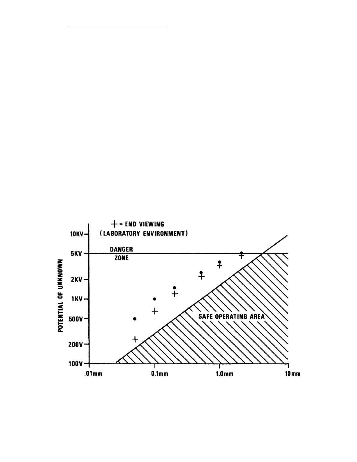
When operating at probe-to-surface spacing of less than 0.125 inches (3mm) -BEWARE OF PROBE-TO-SURFACE ARC-OVER.
Air is subject to dielectric breakdown when the probe-to- surface spacing is low
and the surface voltage is high. A destructive arc-over can occur damaging the
surface under test and/or the sensitive circuitry of the probe.
REFER TO FIGURE 2-1 TO DETERMINE THE SAFE PROBE-TO-SURFACE
SPACING FOR A GIVEN UNKNOWN VOLTAGE.
Probe to surface spacing should be maintained as close as physically reasonable
for best performance. Typical spacing range is from .005" (0.1mm) for unknown
voltages below 500 volts to over .125" (3mm) for unknown voltages up to 3000
volts.
As probe to surface spacing increases instrument performance will suffer:
1. Decreased Accuracy
2. Decreased Speed-of-Response
3. Decreased Surface Resolution
4. Increased Noise
5. Increased Drift
ARC BR EAKDO W N VS. P RO BE-T O-SURF AC E SPAC IN G
TYP. BREAKDOWN TEST DATA • = SIDE VIEWING
PROBE-TO-SURFACE SPACING
FIGUR E 2-1
8
Page 9

D. SYSTEM GROUNDING:
The instrument is normally grounded via power cord and the potential measured is
referenced to ground. A rear panel ground connection is provided.
E. OUTPUT CIRCUITRY:
The output connector is a BNC connector mounted to the rear panel. The output
voltage is the measured voltage divided by 1000. Range is ±3V.
F. REMOTE CONTROL (SLAVE CONTROL):
Provision is made for remote operation via J204 located on the rear panel.
External connections can be made as follows:
1. Parallel connect the inner and outer connection of the slave plugs of all
units.
2. Connect any solid state switch or relay capable of switching 30V DC and
sinking n x 10 mA DC, where n is the number of units to be controlled.
NOTE: Low side of switch must be system GRD.
G. MULTIPLE-UNIT. MASTER/SLAVE CONNECTION:
The 244A is designed to facilitate control of the standby/operate mode of slave units
by a master unit.
External connections are made as follows:
1. Connect all slave units (units to be controlled) as indicated in Section F.
2. Terminate the center conductor of the slave plug to the center conductor
of the master, and outer conductor with the outer connection.
9
Page 10

CONTROLS AND INDICATORS
FRONT PANEL CONTROLS - FIG. 3-1
A. STANDBY/OPERATE SWITCH:
Controls the operating condition of the unit.
1. STANDBY - Starts the probe oscillating, but leaves the H.V. disabled, unless
activated by the remote (rear "slave") connector.
2. OPERATE - Turns on the H.V. supplies, only if the probe is plugged in and
the fork is oscillating. This position overrides the remote control.
B. ON INDICATOR:
Indicates that the low voltage supplies are on and operational status is
controllable by remote operation.
C. OPERATE INDICATOR:
SECTION 3
Indicates that the H.V. is on and that the probe housing may be at any voltage
up to ±3400V. Excessive gain or excessive loading on the probe such as probe
contact to a grounded surface, causes the operate light to blink, indicating a
malfunction.
D. BALANCE:
Balances internal probe contact potential to obtain probe to surface spacing
insensitivity. This adjustment procedure is described in Section 4B (may also be
used for large zero offset when spacing insensitivity is not needed).
E. ZERO:
Compensates for unwanted offsets in the range of ±4 volts. This does not affect
probe-to-surface spacing sensitivity.
F. RESPONSE SPEED (GAIN):
Adjusts system speed-of-response, static accuracy and stability by varying openloop system gain. Excessive gain causes system instability and degradation in
static error. Insufficient gain produces static error and slow speed- of- response.
System gain and responses vary with probe-to- surface spacing and must be
compensated by adjustment of this control.
G. PROBE CONNECTOR:
Connector for attachment of 1017 probes. The connector is interlocked with the
operate switch and will shut down the high voltage section when probe is
disconnected.
NOTE: A special shortened pin is used in P201 (on probe) for safety purposes in
other instruments in the ISOPROBE Series.
10
Page 11

REAR PANEL CONTROLS - Fig. 3-2
H. RECORDER OUTPUT:
Output is 0V±3V for full scale. A BNC connector is provided on the rear panel.
The output voltage is equal to the voltage measured divided by 1000. Minimum
load resistance is 1k ohm.
I. MASTER JACK:
Allows other units with slave connections to be operated by this unit. The output
provides a switch closure when the front panel standby/operate switch is in the
OPERATE position.
J. SLAVE JACK:
Input for remote enable/disable of the high voltage section. In STANDBY a
closure between the center and outer conductors of the plug will enable the high
voltage if the probe is attached and the fork oscillating. The remote can be
overridden by switching the front panel switch to either OPERATE or OFF. The
switch should be capable of handling 30V open and n x 10mA, where n is the
number of units being controlled.
K. POWER ON/OFF SWITCH:
Main power to instrument is on when red ring is visible on side of rocker.
L. GROUND JACK:
5 way binding post connected to power line ground to provide system ground.
M. FUSE DRAWER:
Contains fuses and line voltage switching selector insert. Refer to "CAUTION"
note on Page 4.
11
Page 12

12
Page 13

SECTION 4
OPERATION
CAUTION:
Verify that instrument operating voltage matches local power line voltage. Refer to
Section 2.
PRECAUTIONARY NOTE
Model 244A is a non-contacting voltmeter. The potential of the probe will attempt to
follow the potential of any object within the field of view of the sensitive electrode (up to
±3400 volts) when the instrument is operating. In the interest of operator safety and also
to reduce high voltage stress within the instrument, it should be left in the STANDBY
mode whenever it is not being used and particularly when the probe will not be "looking"
at a surface of less than 3000V.
A. INITIAL SET-UP:
1. With PROBE mounted as previously described in Section 2, connect
probe plug to the probe receptacle on the instrument front panel.
2. Switch STANDBY/OPERATE switch to OPERATE.
3. Set RESPONSE SPEED (GAIN) control according to the probe-to-sur-
face spacing and desired speed-of-response. In the event the front panel
meter is the sole indicator of the instrument output, the normal static error
is very small and speed-of-response is non- critical. For 1/8" (3mm)
spacing, set at
½
of CW rotation.
NOTE:
Decreasing the probe-to-surface spacing has the same influence as increasing
the GAIN control. The GAIN control should, therefore, be re-adjusted whenever
the probe-to-surface spacing is altered if optimum speed-of-response is desired.
a. Connect a DC supply through a switch to a metal plate at the same
probe-to-surface spacing to be utilized (preferably the same surface if
practicable) as shown in FIGURE 4-1.
F
I
G
U
R
E
4
-
1
* Switch with low contact bounce - preferably H.V. Reed Relay Contact
b. Connect the OUTPUT to a recorder or scope.
13
Page 14

c. While closing the switch, observe the instrument output and adjust
GAIN for fastest speed-of-response with minimum overshoot in
step response.
Once properly adjusted, the GAIN control should require no
further attention unless the probe-to-surface spacing is altered.
The static follow-up error (difference in DC potential between the
unknown and the probe) of a carefully zeroed and adjusted
instrument is typically less than 0.05% throughout its range.
d. With the probe aperture viewing a zero volt (or grounded) surface,
set ZERO control at mid-range. Adjust BAL (balance) control for
near zero reading.
B. SPACING INSENSITIVITY OVER LARGE PROBE-TO-SURFACE SPACING
RANGE:
This adjustment procedure will minimize offset errors due to variations in probeto-surface spacing. This adjustment is preferably done with a mechanical
positioning device and a grounded plate.
1. Position probe for minimum probe-to-surface spacing.
2. Adjust for a meter reading of zero, as described in Sect. A3d above.
3. Re-position to maximum probe-to-surface spacing and adjust BAL
control for a meter reading of zero.
4. Return to the minimum spacing and re-adjust ZERO. Repeat this
procedure until the degree of spacing insensitivity desired is reached.
The stability of this adjustment is directly related to zero drift and the
probe-to-surface spacing.
14
Page 15

SECTION 5
THEORY
A.
GENERAL: Principle of Operation (See Figure 5-1)
The electrostatic electrode "looks" at the surface under measurement through a
small hole at the base of the probe assembly. The chopped A.C. signal induced
on this electrode is proportional to the differential voltage between the surface
under measurement and the probe assembly. Its phase is dictated by the D.C.
polarity.
The reference voltage and this mechanically modulated signal, conditioned by
the high input impedance preamplifier and signal amplifier are fed to a phase
sensitive detector whose output D.C. amplitude and polarity are dictated by the
amplitude and phase of the electrostatically induced signal relative to the
reference signal. The output of the phase sensitive detector feeds a D.C.
integrating amplifier. Its output polarity is inverted to that of the unknown. The
output of this amplifier is used to drive a H.V. amplifier (AV = -300) which in turn
drives the probe to the same potential as that of the surface under
measurement.
The probe is driven to a D.C. voltage typically within 0.1 % of the potential of the
unknown for a .040" probe-to-surface spacing. By simply metering the output of
the H.V. amplifier, one has an accurate indication of the unknown potential.
B. NULL BALANCE:
This instrument's basic operating principle, i.e., "field-nulling" provides a high
degree of immunity to errors in measurement caused by variations in probe-tosurface separation,. (As long as the probe and the surface under measurement
are at the same potential the electrical field between them is zero, neglecting
fringing, regardless of the probe-to-surface distance.)
If, however there exist voltage sources in the vicinity of the sensitive electrode
which are independent of the unknown to be measured, the offsets produced will
detrimentally affect the spacing independence. Such voltage sources include
contact potential differences among the internal probes parts, small specks of
charged dust particles, etc.
The null balance circuitry is provided to neutralize such offsets by applying a
voltage directly to the sensitive electrode.
C. ZERO:
The instrument's zero control is a voltage source connected in the metering
circuitry. It is used to overcome offsets produced by voltage sources external to
the probe.
D. GAIN:
The instrument functions as a closed loop unity gain voltage follower. Its open
loop gain from probe to integrator is determined by the gain of various amplifiers.
The exact gain required for optimum transient responses during a specific
measurement is determined by the probe-to-surface spacing used. In order to
accommodate measurements at various probe-to-surface spacings, a front panel
gain control is provided which controls the gain of the signal amplifier.
14
Page 16

Isoprobe® Electrostatic Voltmeter
Simplified Block Diagram
FIGURE 5-1
15
Page 17

APPENDIX I
MODEL 1017 PROBE MOUNTING
The Monroe Electronics, Inc. Model 1017 Miniature Probe is intentionally constructed
with no mounting devices as any such mounting device would serve only to enlarge the
physical dimensions. It is, therefore, left to the user to devise a method of mounting the
probe to suit his individual needs and to realize the fullest potential of the inherently
small size.
As supplied, the probe is partially jacketed by a length of irradiated polyolefin shrinkable
tubing. This jacket provides insulation of sufficient dielectric strength that the probe may
be hand-held or clamped using light pressure for use within the operating range of the
Model 244A ISOPROBE Electrostatic Voltmeter.
This tubing is otherwise not essential to the operation of the probe. IT MAY BE
REMOVED AND DISCARDED, IF DESIRED. It must, in fact, be removed if the probe is
to be disassembled for any purpose such as cleaning (in those procedures involving
removal of the case). A sharp model maker's knife may be used to slit the tubing using
CAUTION to assure that the cable jacket is not nicked or slit.
If replacement is required, a 25/s inch length of ALPHA FIT221-3/s or equivalent is
recommended. Apply heat only long enough to shrink the tubing in place as damage to
the sensitive electronics and adhesives within the probe may result from prolonged
elevated temperature on the outside of the case.
When devising fixturing for the Model 1017 probe, consideration must be given to the
fact that the normal operating range of the Model 244A ISOPROBE®Electrostatic
Voltmeter is ±3000 volts and that the probe assumes the potential of the surface under
measurement within these limits. The probe, therefore, must be insulated from other
parts of the system.
Choice of insulating materials, although not critical in many applications, should be
limited, if possible, to "leaky" dielectric materials with relatively low volume resistivities
(in the general order of 1010 ohm-cm) as opposed to those such as polystyrene which is
a very good insulator. Example of "leaky" insulators are the phenol- ics. The primary
purpose in this is to provide a discharge path for the insulator which has a short
relaxation time. This is especially important in the vicinity of the sensitive aperture.
The Model 244A is capable of driving a capacitive load of several hundred picofarads
without severe degradation in performance. It is possible, therefore, to attach the probe
to some fixed portion of the apparatus via a metal clamp, so long as the metal clamp is
insulated from the remainder of the apparatus.
In any friction clamp design, the pressure (unit force) on the probe case should be kept
low, thus over as large an area of the case as possible as distortion of the gold plated
brass may otherwise occur.
16
Page 18

One possible configuration is illustrated in Figure A-l-1.
For general bench use burette or utility clamps attached to a ringstand or similar support may
prove adequate. These are available from scientific supply houses.
An attractive alternative to clamping is the use of double sided adhesive tape or fast-setting
polymerizing adhesives such as LOCTITE1 SuperBonder 495 cyanoacry- late adhesive or
equivalent which does not require long setting or curing time and provides a relatively permanent
bond. LOCTITE* is a registered trademark of and is available from: LOCTITE CORPORATION
Newington, CT 06111 (208)278-1280
17
Page 19

APPENDIX II
10X GAIN MODIFICATION
(For use with high resolution probes)
Due to the smaller aperture in high resolution probes (1017EH, 1017SH, 1017EJ),
electrostatic gain is lowered. As a result, it may not be possible to achieve optimized
transient response except at extremely close spacing.
System gain may be increased approximately tenfold by replacing R63 (10K, adjacent to
A5 in front corner of main PC board near meter – refer to picture) with a 1K, 14 W, 5%
carbon composition resistor.
To replace resistor:
1. Remove cover and locate R63.
2. Remove bottom panel from instrument (two #6-32 screws in center of
side panel).
3. Carefully remove the two #6-32 screws which hold the front panel to the
side rails (screws located just behind front feet) and move front panel so
that it does not interfere with replacement.
4. Unsolder and replace resistor.
5. Re-assemble instrument.
After this change has been made, adjustment of front panel gain will be difficult at close
probe-to-surface spacing when using standard probes. It is therefore suggested that
units so modified be tagged in some manner to alert the unwary user.
Front
Panel
18
Page 20

APPENDIX III
MODEL 1017 PROBE CLEANING PROCEDURES
DISASSEMBLY AND CLEANING:
It is impossible for the sensitive aperture in the probe to be covered by a window of any
sort which will permit the probe to operate normally.
So long as this aperture is open, foreign material may enter the volume associated with
the vibrating vane and generate undesired noise or DC offset, thereby impairing the
accuracy and utility of the instrument.
To maintain low noise and low offset, it is important that the probe be operated in as
clean an environment as practicable, that it be purged with filtered air or an inert gas
such as clean, dry nitrogen, and that it be periodically disassembled and cleaned.
Where practicable, it is recommended that the probe be installed with the sensitive
aperture downward and when not in use, wrapped with aluminum foil.
The necessity for cleaning is indicated when:
1. The output as indicated by the meter or the recorded record is excessively
noisy.
2. It is no longer possible to "null balance" the instrument using the BAL
adjustment and still remain within the range of the ZERO adjustment.
Cleaning Procedure #1
Disconnect probe cord from main unit.
1.
2. Remove probe from fixturing device if used.
3. Remove screw closest to sensitive aperture and loosen screw closest to
cable end.
4. Carefully slide cover directly off of probe.
NOTE: Some probes have one or more shims between the base and the
case. These will fall out of the case when it is removed. Retain them.
5. Once the case is removed and until it is replaced, the two vanes are
exposed and subject to damage, therefore, during cleaning VERY
CAREFUL HANDLING is required.
8. Cleaning should be done using an aerosol isopropyl alcohol or equivalent
solvent.
9. Areas to be checked for cleanliness are:
a. ) Sensitive electrode.
b. ) Two vanes, especially in the area of the sensitive electrode (both
sides).
c. ) The aperture in the case and surrounding area (inside and out).
6. CAREFULLY slide case back onto probe. Shim(s), if any, should be slid
into the case first in such a way that the hole in the shim(s) will be lined up
with the screw hole (in the case) closest to the aperture so that when the
screw is replaced, it will extend through the shim(s) before entering the
threaded hole in the probe base.
7. The toe of the base plate should abut the inner surface of the end of the
case.
8. Tighten screws with torque consistent with their size.
19
Page 21

Cleaning Procedure #2
NOTE: Use this procedure only if aperture diameter is 1.75 mm or greater.
1. Disconnect probe cord from main unit.
2. Immerse approximately 1 cm of the end of the probe in the cleaning fluid.
NOTE: Cleaning solvent to be CLEAN ethyl or isopropyl alcohol.
3. Clean until no dirt is visible in aperture.
4. Allow all solvent to evaporate before operating probe.
Cleaning Procedure #3 (Using ultrasonic cleaner for probes with small apertures.)
1. Remove case as described in Cleaning Procedure #1.
2. Immerse end of vanes and electrode housing in clean isopropyl alcohol in
ultrasonic cleaner, when clean, set aside to allow solvent to evaporate.
3. Clean case thoroughly in same solvent.
4. Reassemble as in Cleaning Procedure #1.
20
Page 22

APPENDIX IV
MODELS 1017E/22D AND 1017S/22D GRADIENT
ADAPTERS
A. SPECIFICATIONS:
Range: With Model 244 or 279; 0 to ±3000 volts/mm (Refer to Note 1)
Accuracy: Better than 2% (Refer to Note 2)
Drift: <0.01 V/mm per hour (Refer to Note 2)
Noise: With Model 244 or 279; <0.3 V/mm RMS <2V/mm p-p referred to input
(Refer to Note2)
Speed of
Response: With Model 244 or 279; <4 mS max. 3 mS typ., 10% to 90%
Resolution: Approx. 3 cm dia. spot (Refer to Note 2)
Dimensions: 19/32” (40mm) dia. x 11/8” (29mm) high
Attitude: End-view is axial
Side-view is radial
NOTES:
1.) Limited to approx. 2kV/mm air gap breakdown
2.) Specified uncontaminated atmosphere at 1 centimeter probe-to-surface
separation
B. DESCRIPTION:
These adapters are designed to convert an ISOPROBE Electrostatic Voltmeter
into an Electrostatic Fieldmeter. This fieldmeter mode of operation makes
possible non-contacting measurement of surface potentials of virtually any
magnitude so long as the probe is mounted at the proper distance.
The adapters consist of a metal cup with a carefully chosen aperture, through
which the Model 1017, or 1034 probe “looks”, attached to a small insulated box
designed to slip over the end of the probe and a 10 foot flexible grounding wire
which is attached to the metal cup.
C. INSTALLATION:
1017E/22D: Using a 1/16” Allen wrench, retract the setscrew enough to allow the end of
the probe to slide in to the square opening until the apertures align. Gently re-tighten the
setscrew against the probe case and back off 1/4 turn. DO NOT OVERTIGHTEN. The
adapter is now prepared for calibration.
21
Page 23

1017S/22D: Remove the #0-80 x 3/32” machine screw from the end of the probe nearest
the aperture end of the probe. Replace the screw just removed with the longer #0-80 x
3/16” machine screw furnished with the gradient adapter. Slide the probe into the
adapter until the apertures align. Snug the screw against the body of the adapter and
back off 1/4 turn. DO NOT OVERTIGHTEN. The adapter is now prepared for calibration.
D. CALIBRATION:
Calibration of the Model 1017E/22D Gradient Adapter is acheived by sliding the
adapter forward or backward on the probe until the ISOPROBE® Voltmeter
output indicates exactly one-tenth of a known applied voltage at 1 cm probe-tosurface spacing.
Calibration of the Model 1017S/22D Gradient Adapter is accomplished by offcentering the aperture of the gradient adapter in relation to the aperture of the
probe until the ISOPROBE® Voltmeter output indicates exactly one-tenth of a
known applied reference voltage at 1 cm probe-to-surface spacing. This offcentering action is accomplished by sliding the adapter forward or backward on
the probe case.
Note: In either event above, the Gradient Adapter plate should be grounded to
the electrostatic voltmeter frame and the instrument must be properly zeroed.
(See operating instructions.) Tighten the screw sufficiently to hold the adapter in
place DO NOT OVERTIGHTEN and re-check calibration.
22
Page 24

PREVISION NOTES*
MODEL 244AK
The Monroe Electronics Model 244AK is virtually identical to Model 244A except that:
The Recorder Output of Model 244AK is
1/2ooth
of the ±3000 volt range of the instrument thus
producing an output signal of up to ±15 volts capable of driving 5000 ohms or greater.
The above should be borne in mind when using this manual.
M O D E L 2 4 4 A K O U T P U T S T A G E
23
 Loading...