

Page 1

Contents
Page
Introduction 2
Safety Instructions 3-4
Recycling 4
Unpacking 5
Foot/SpikeFixing 6
AmplifierPanel and Controls 7-10
Positioning& Set Up 11
Specification 12
Guaranteeand Service 13
Claims under this guarantee 13
EC Declaration of Conformity 14
Data Protection 15
OwnerInformation 15
WarrantyCard – Fold out section in back cover
© Monitor Audio 2005 RS W12 Rev 1
1
Page 2

Introduction
Thank you for your purchase of Monitor Audio Silver RS W12 subwoofer, which
has been designed and constructed using quality systems and materials to
provideyearsof enjoyment, reliability and pride of ownership.
This product, as with all the Silver RS range, is hand crafted from top to bottom
using traditional woodworking skills for our sumptuous cabinets, married with
thestate of the art technology of our renowned driveunits.
Music is and should be a natural enhancement of life. It stimulates the
imagination, changes your mood, helps you relax, and provides endless hours of
entertainment.
At Monitor Audio we pride ourselves in attempting to make the listening
experienceas close as possibleto the original ‘music’ production,or as we say at
MonitorAudioour aim is to make the musicexperience “As close as it gets”.
Please read through this manual to familiarize yourself with any safety advice
and how best to set up your subwoofer to achieve the very best listening
experience.
Please retain this manual forfuture reference.
© Monitor Audio 2005 RS W12 Rev 1
2
Page 3
Safety Instructions
1. Read Instructions
Please read and follow all of the instructions in this manual before
enjoyingyour subwoofer.
Any instructions preceded by this warning triangle MUST be followed.
Failureto do so may cause personal injuryordamage the unit/s
2. Lifting/Moving
Due to the extreme weight of the RS W12, care must be taken at all times
whenhandling the product and we recommenda 2-person lift.
3. Power
If the RS W12 is not likely to be used for extended periods we would
advise it is switched off at the mains power supply. This is a
recommendedsafepracticein order to reduce the risk of electricalfire.
4. Power Cord Protection
The power supply cord should be routed so that it is not likely to be
steppedon or pinched by items placed upon or against it.
5. Water & Moisture
The RS W12 should not be used near water - for example, bathtub,
washbowl, kitchen sink, and washing machine, in a wet basement or
near a swimming pool. Under no circumstance should plants or fish
bowls be placed on the product. Please ensure that no liquid is spilt
on the appliance, especially on the rear panel where the power cord
enters the amp.
6. Heat/Humidity
TheRS W12 shouldnotbe placed nearany heatsourcesuch as radiators,
open fires, stoves, direct sunlight and any other appliance that produces
heat.
This product is designed for use within the home environment. Exposure
to extreme temperatures & humidity when placed on patios or open
conditionscouldadverselyaffect the wooden cabinet.
7. Ventilation
The RS W12 should be situated so that its location or position does not
interfere with its own proper ventilation. For example it should not be
placed on a sofa, bed or deep pile rug or similar surface that may impair
any ventilationopenings. It should not be placed in any purpose built
location without suitable ventilation being provided.
© Monitor Audio 2005 RS W12 Rev 1
3
Page 4

8. Damage requiring Service
Qualifiedpersonnelshouldservicetheappliance when:
Thepowercord or plughas been damaged.
Liquidhas been spilt on therear panel.
TheRS W12 has been droppedor the enclosuredamaged.
The RS W12 does not appear to operate normally or exhibits
a marked change in itsperformance.
9. Servicing
The user should not attempt to service the appliance beyond that
specified in this manual. Only qualified personnel should carry out all
otherservicingrequirements.
10.Cleaning
Before cleaning it is advisable to disconnect the RS W12 from the power
supply.
Avoid touching the RS W12 drive unit whilst cleaning, as any damage will
impairitsperformance.
You will fully appreciate that great care and attention has gone into the
materials chosen to produce the Silver RS W12. It is our intention that it
should provide a lifetime of musical pleasure. A gentle wipe with a dry,
clean cloth is all that is required to remove any dust. Treat it as you
woulda fine pieceoffurniture because that ishowit has beendesigned.
11. Natural Wood Veneers
MonitorAudiotakes great pride in providinga high quality product.
We use only hand selected natural wood veneers, which are carefully
matchedand hand finished to the highest standard possible. The unique
nature of each veneer may result in natural colour variation and grain
from samples you may have seen in photos or at the dealer’s show room.
Thisis what makes theproducta special pieceof furniture.
If your speaker is finished in a Cherry veneer please be aware that it will
naturallydarken with age more so than other types ofwood veneer.
© Monitor Audio 2005 RS W12 Rev 1
4
Page 5
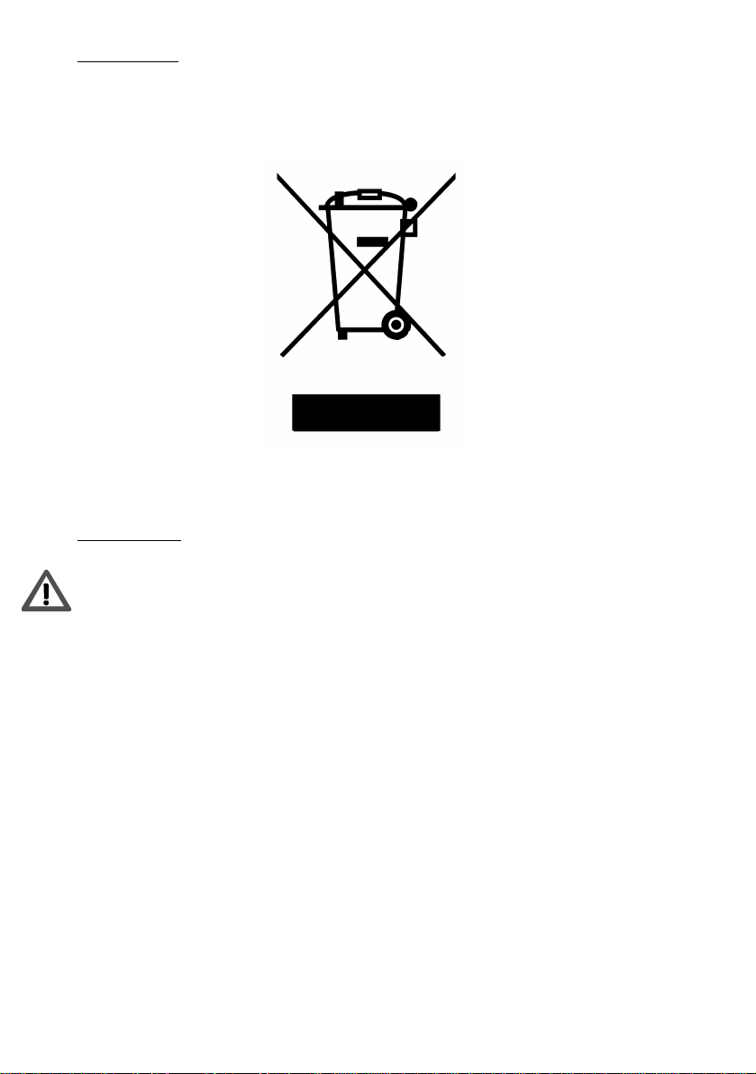
Re-cycling
When it is time to replace your RS W12 please help us protectthe environment by
disposingofit in an appropriateand responsible manner.
Furtherdetailsare available fromwww.monitoraudio.co.uk
Unpacking
Care must be taken at all times when handling the RS W12 due to the extreme
weightof the product. We recommenda two-person lift whereverappropriate.
The feet/spike assemblies and mains power cord/s are contained in separate
protectivecardboardsleeves and shouldberemoved.
Please select the power cord appropriate to your Country/location. Mains
voltage selection for 120 or 230 Vac operation is electronically auto selected.
To remove the RS W12 from its carton place some protective material on thefloor
and having removedany items of packing from the top of the pack carefully invert
the carton. (Also see icons on the carton). Gradually pull the carton upwards to
exposethe subwoofer, which will be presentedwith its base uppermost. Remove
fixing tape from plastic bag and expose the base/cabinet to allow fitting of the
spikedfeetinto the M10 threadedinserts as describedonpage 6
© Monitor Audio 2005 RS W12 Rev 1
5
Page 6

Spiked Foot Fixing For Carpeted Floors
The amazingly engineered composite Silver RS series foot encorporates a spike
for use on carpeted floors and also, a soft polymer pad (for use on wooden or
tiledfloors).
Please ensure there are no
hidden wires under the carpet, or
Locking Nut
Main Threaded
Assembly
Soft Polymer
Spike
The foot comes fully assembled for use on
carpeted floors. All that is required is fixing
into the plinth. This is achieved by simply
screwing the feet fully into the 4-threaded
insert in the underside of the cabinet. If your
carpet has a very thick pile, remove the soft
polymer pad from the foot to ensure the
spike goes right through the carpet into the
floor. With great care turn your cabinet the
right way up. Place the cabinet in your
desired location, and check that it is level on
all sides. If it is slightly off level, unscrew the
spike at the lowest point and check again.
Continue this process until the cabinet is
fully level. Use the locking nut on the foot to
fix the foot in place and to stop any unwanted
vibrations.
trailing mains leads that could be
damaged by the spikes.
Spiked Foot Fixing For Wooden/Hard Floors
For use on solid floors or where spikes
are inappropriate, it is possible to use the
foot without the spike insert. To use the
foot in this manner carefully grip the
knurled portion of the spike and rotate
anti clockwiseto unscrew the spikefully.
You may find it easier to first remove the
polymer pad to gain more purchase on
thespike.
The pad should be replaced before
carrying out the levelling operation
previouslydescribed.
© Monitor Audio 2005 RS W12 Rev 1
6
Page 7

Amp Panel and Controls
123
45689
71112
13
10
10a
7
© Monitor Audio 2005 RS W12 Rev 1
Page 8

1. Stand-by / On Indicator
TheLEDindicates whether the unit isin stand-by mode or operational.
2. Crossover Frequency Control
The crossover frequency control only operates when the low pass filter switch
(refer to section 3.) is in the ‘In’ position. The crossover frequency control is used
to set the upper frequency limit (low pass) of the RS W12. The crossover control
should be set in accordance with the size or bass output of the main/satellite
speakers. Refer to the chart below as a guide to setting the crossover frequency
control to the optimum position. Much will depend on the correct low frequency
response of the main speakers and their position in your room. Experimentation
is advisable.
Type of main speaker Crossover control setting
Large floor-standing speaker 40-60 Hz
Small floor-standing speaker 50-70Hz
Large stand-mount/ bookshelf speaker 50-80 Hz
Small stand-mount/ bookshelf speaker 60-90 Hz
Small satellite speaker 80-160 Hz
3. Low Pass Filter Switch.
When set to the ‘In’ position the crossover frequency control (section 2) is
activated and can be adjusted from 40Hz to 120Hz using the crossover frequency
control. When set to the ‘In’ position it can be used with an amplifier that does
not have a dedicated sub-woofer or LFE output, such as a stereo 2-channel
amplifier. If the amplifier or A/V processor has a dedicated LFE or sub-woofer
output, the Low pass filter switch should be set to the ‘Out’ position. The low
pass filter will then be set by the amplifier internal filter. This should be set in
accordancewiththeamplifieror A/V processoruserguide.
4. Phase Control Switch
The Phase Control is used to synchronise any delay between the RS W12 and
main/satellite speakers. When the RS W12 is in phase with the main/satellite
speakers the sound should be full bodied. Sit in a normal listening position
whilst adjusting the phase switch. Help fromanother person may be required in
ordertodo this easily. When set correctly the locationof thesubwoofershouldbe
almost undetectable. Experimentation is advisable in order to achieve optimum
results. However it should be noted that in most cases the phase control switch
should be set to 0 degrees, especially when using a digital A/V processor or A/V
receiveramplifier.
© Monitor Audio 2005 RS W12 Rev 1
8
Page 9

5. Power Mode Switch with On-Auto-Off Facility
The Power Mode Switch has three positions: ‘On’–‘Auto’–‘Off’. When the switch
is in the ‘Off’ position the subwoofer will not function. In the ‘Auto’ position the
subwoofer will automatically switch on when an input signal is received. It will
remain on. Ifno signal is receivedfor around 15-20minutes, the RS W12 will then
switch into standby mode until a signal is received once more. With the switch in
the‘On’ position, the subwoofer is permanently switched on underall conditions.
6. RCA Line Level Inputs (Left & Right)
This is the only method of signal input connection to the RS W12. When using a
stereo amplifier system, connection can be provided by a pair of high-quality
signal cables from the pre-out section of an amplifier. If a digital A/V processoror
A/V receiver/amplifier is to be used, a single cable can be connected from the
‘sub out’ or LFE connection on the amplifier to the RCA input connection on the
RS W12 labelled ‘R’. The RCA input marked ‘L’ in this case will remain unused.
Note: - cable lengths should not exceed 10 metres to avoid interference from
other electrical appliances.
7. RCA Line Level Outputs (Left & Right)
RCA line level outputs are provided in order to use other sub-woofers in
conjunction with the RS W12 by ‘daisy chain’ type connection. The outputs are
link out only connectionsand do not provide anyform of filtering.
8. Warning Information
Thefollowingwarning symbols are found on theamp panel. Themeaningsare:
Thislighteningflash with an arrow head symbol, within an
equilateraltriangle,is intended to alert theuser to the
presenceof uninsulated “dangerous voltage”within the
productsenclosurethatmay be of sufficient magnitude to
constitutearisk of electric shockto the persons.
Waning: To reduce the risk ofelectric shock, do not
removecover(orback) no user-serviceableparts
inside. Refer servicing to qualifiedservicepersonnel
Thisexclamationpointwithinan equilateral triangle is
intendedtoalert the user to presence of important
operatingmaintenance(servicing)instructionsinthe
literatureaccompanyingtheappliance
© Monitor Audio 2005 RS W12 Rev 1
9
Page 10

9. Mains Power Switch
The Mains Power Switch should be switched to the ‘Off’ position when the
RS W12 will not be used for extended periods. The switch must be in the ‘On’
positionforthe sub-woofer to function.
10. IEC Mains Power Connector/ Fuse Location
The RS W12 is supplied with a two-pin mains input socket for connection to the
mains supply. Use ONLY the appropriate IEC mains lead provided with the
product. Also fitted is an external mains fuse. If a fuse blows during operation a
spare fuse is provided within the fuse holder for replacement. If you wish to
change the fuse, you can do this by removing the IEC mains lead and carefully
levering out the original fuse from its holder below the IEC mains input socket
(9a). If the fuse blows again it is advisable to seek help from an authorised
service agent. DO NOT attempt to re-fit a further fuse as this could result in
serious damage to the amplifier unit.
11. Volume Control
This control allows the level or volume to be adjusted in order to achieve a
balanced overall sound. To use this facility you will need to play a selection of
familiar music or film excerpts. Start with the volume at minimum and increase
the level control until a balanced sound is established. If using an A/V processor
or A/V receiveramplifier, the system can adjusted by the test tone functionwithin
the set-up features. (refer to the set up section in the A/V processor or A/V
receiver amplifier user guide.) When the RS W12 is correctly set-up, you should
notbeable to identify its location easily in the room.
12. EQ 1 setting
The EQ 1 setting should be set as a default option. This will provide the best
overall transient response and power output. This setting will provide a
maximally flat response suitable for music or Music video. Note: Frequency roll
off starts at 27Hz
13. EQ 2 setting
The EQ 2 setting should be used when an emphasis in the low frequency is
required. An additional boost of 4dB will be provided at 21Hz to give impact
essentialfor action movies.
The EQ1 and EQ2 settings can also be adjusted to suit personal taste. This is
doneby pressing the buttons located onthe control panel.
© Monitor Audio 2005 RS W12 Rev 1
10
Page 11

Positioning/Initial Set Up
The RS W12 should now be sited in the most suitable position, preferably not
directly in the corner of a room as this may cause excessive bass boom. Once a
desirable position is achieved it is important to check if the cables are long
enough to reach comfortably without being under tension. Leave the RS W12
unplugged until the installation procedure is completed. The optimal control
settingswilldepend entirely on your system configuration. For initial trialsset the
controlsas follows:
Volumecontrol Shouldbe set to minimum
Frequencycontrol Shouldbe set to theminimumposition (40Hz)
Phase control Shouldbe set to zerodegrees
Powerswitch Shouldbe set to ‘Auto’
EQ1 setting Shouldbe selected
Lowpass filter switch Shouldbe set to the ‘Out’ position
Inputconnectionscan be made at this stage before the power is connected to the
RSW12. Pleaserefertopage7 for set up and fine-tuning.
Neverconnector disconnect the RCA inputlead connection with the RS W12
switchedon.
Set Up
Once the input cables are connected and the controls are set in accordance with
the initial set-up procedure above, the RS W12 can be connected to the mains
power supply and switched on. Do not play any music at this stage. With the
Power Mode Switch in the ‘Auto’ position, the unit should remain in standby until
a signal is received.
Play a variety of music/ film excerpts starting at a very low volume level,
increasing to an average listening level once you are sure everything is working
correctly. Check the back of the RS W12, the LED indicatorshould now indicate it
is ‘ON’. Please nowfollow the bulleted instructions below: -
For use with an AV amp/receiver (product with Subwoofer output) please
select the low pass filter switch to the ‘Out’ position. Otherwise select
low pass filter switch to the ‘On’ position, to engage the crossover
frequency control,ref. Page 8.
If using the crossover frequency control please adjust in accordance with
thetable on page 9 furtherfine-tuning may be required.
Adjust theVolumeControlto desired level for initial trials, ref. page10
The Phase Controlcan now be setref. Page 8
The volume control can now be set to finish the set-up procedure. It is important
to try a variety of musicand film excerpts with which you are familiar in order to
obtainthe optimum overall settings.
© Monitor Audio 2005 RS W12 Rev 1
11
Page 12

Specification
Lowfrequency limit:- 21Hz (EQ1) 27Hz (EQ2)
Upperfrequencylimit:- 40 – 120 Hz Variable
Lowpass filter alignment:- Active4thorder24db/octave(two-stagefilter)
CabinetSpecification: - SealedCabinetwith25mm M.D.F construction
withinternalbracing
AmplifierOutput:- 500 Watts (R.M.S) 1000 Watts(Peak)
Amplifierclassification:- Class- D Digital amplifier
Drivercompliment:- 1 x 12”C-CAM®sub-wooferdriverfeaturing
triplesuspensionand 3” longthrowvoicecoil
Dimensions:- Millimetres:- 340 H x 340 W x 370D
Inches:- 13 3/8 x 13 3/8x 14 ½
All dimensionsexcluding grille
Weight(unpacked) 25.5 Kg (77lbs)
InputImpedance: - 20K Ohms
Mains input voltage:- 115 Vac / 230 Vac
(ElectronicallyAutoselected)
C-CAM®is a registered trade mark ofMonitorAudio Ltd
© Monitor Audio 2005 RS W12 Rev 1
12
Page 13

Guarantee and Service
Valid upon completion of the incorporated warranty card and its return within 30
days of purchase.
This equipment has been fully tested prior to dispatch from the factory. Both the
craftsmanship and the performance of this product is guaranteed against
manufacturing defects for the period of one year from the date of purchase (see
conditions below), provided that the product was supplied by an authorised
MonitorAudioretailerunder the consumersale agreement. (The words ‘consumer
sale’ shall be construed in accordance with section 15 ofthe supply of goods act
1973). Monitor Audio accepts no responsibility for defects arising from accident,
misuse, abuse, wear and tear, modification or operation outside of that specified
within this instruction manual. Neither will responsibilitybe accepted for damage
or loss occurring during transit to or from the parties claiming under this
guarantee.
This guarantee covers both labour and parts. The liability of Monitor Audio is
limited to the cost of repair or replacement of the defective parts (at the
discretion of Monitor Audio) and under no circumstances extends to
consequentiallossesor damage.
Claims under this Guarantee
The equipment should be returned in its original packaging to the original
supplier where possible, or to any other authorised Monitor Audio dealer. If it is
not possible to return the equipment by hand, then it should be sent carriage
prepaid via a reputable carrier. If the original packing is not available
replacement packaging can be purchased from Monitor Audio. If you have any
difficulties complying with these requirements please contact us at the following
address:
CustomerService Tel: 44 (0) 1268 740580
MonitorAudioLtd. Fax: 44(0) 1268 740589
Unit2, 24 BrookRoad Internet:www.monitoraudio.co.uk
Rayleigh Email: info@monitoraudio.co.uk
Essex
SS67XL
England
Thisguarantee does not affectthestatutoryrights of theconsumer under UK law.
© Monitor Audio 2005 RS W12 Rev 1
13
Page 14

EC Declaration of Conformity
EC Declaration of Conformity
lare in own responsibility, that the RS W12 product described in this manual
We, Monitor Audio Ltd.
Unit 2,24 Brook Road
Rayleigh
Essex
SS6 7XL
England
Dec
is in compliance with Technical Standards/Council Directives:
(LVD) 73/23/EEC Low Voltage Directive
EN60065: 09.93+ A11:09.97 Safety requirements for mains operated electronic and related
apparatus for household and similar use.
(EMC) 89/336/EEC Electro Magnetic Compatibility
EN55013: 08.90+A12:08.94+A13:12.96 Limits and methods of measurement of radio disturbance
characteristics of broadcast receivers and associated equipment.
EN55020: 12.94+A11:12.96 Electro magnetic immunity of broadcast receivers and associated
equipment.
05
EN61000-3-2: 04.95+A1:1998+A2:1998 Electro magnetic compatibility (EMC) –Part 3: Limits –
Section 2: Limits for harmonic current emissions(equipment input current up to and including 16
Ampere per phase).
EN6100-3-3: 01.95 Electro magnetic compatibility (EMC) –Part 3: Limits –Section 3 : Limits of
voltage fluctuations and flicker in low-voltage supply systems for equipment with rated current up and
including 16 Ampere per phase.
Dean Hartley (Technical Director)
14 January 2005
Monitor Audio Ltd
England
© Monitor Audio 2005 RS W12 Rev 1
14
Page 15

Data Protection
Weat Monitor Audio arecommittedto respecting the wishesand privacy ofour
customers. Any information you providewillbe held in the strictestconfidence
and only used withintheMonitorAudio organisation for the provision of services
suchas warrantyclaimsorspare parts.
We may wish to contact you in the future to ensure you are happy with the
productsand standards of servicewe provide and to keep you up-to-date with the
latestproductsand promotions we have tooffer.
Shouldyou wish not to be contacted byus eitherby post, e-mail or phone, please
tick the box on the warranty card. Alternatively you can request not to be
contactedin future by writing toCustomerService,at theaddress on the previous
page.
Owner Information
Product Details
Model RSW12
ProductSerialNo …………………………………..
Amppanel Serial No ……………………………..
Dateof Purchase ……………………………………
Dealer Details
DealerName ……………………………………………………………………………………………….
Address ………………………………………………………………………………………………………
Town,Postcode, Country …………………………………………………………………………….
e-mailaddress ……………………………………………………………………………………………
MonitorAudioreserves the rightto alter specifications withoutnotice.
© Monitor Audio 2005 RS W12 Rev 1
15
 Loading...