

Page 1

Owners Manual
series
Page 2

Page 3
Contents
Contents 1
Introduction 2
Set Up and Positioning 2
Radius One 2
Radius 200 2
Positioning - Front Speakers 3
Positioning - Surround Speakers 3
Optimum Speaker Placement 4
Fixing the Radius 225/ Radius One to a Wall 5
Radius 270 Feet and Spikes 6
Specifications 7
Owner Information 8
monitoraudio.com
1
ENGLISH
Page 4

Introduction
Congratulations and thank you for your purchase of the Radius Series loudspeakers.
We are confident they will provide years of enjoyment and pleasure as only high quality
components have been used throughout.
Please follow this user manual carefully as it contains important information about positioning
and set up procedures. For further advanced information please refer to our web site at:
www.monitoraudio.com
The Radius 45 incorporates a thermal protection device, which helps to protect
the drive unit and tweeter from permanent damage. If the speaker stops working
after a long period of play, turn off the source for about 10 minutes, and retry.
Set Up and Positioning
Although position and suitability will have been considered prior to purchasing these
loudspeakers, this section will guide optimum positioning and set up (an illustration is
provided on page 4 to assist with positioning). For instructions on fitting the Radius 225 or
Radius One to a wall, please refer to page 5. The Radius One features fixings compatible
with a Sanus Wall Bracket.
NOTE: The Radius 45 and 90 can be fixed to a wall using our Universal Speaker Mount
sold seperately. The Radius 200 is not designed to be wall mounted.
Self adhesive rubber feet are provided to prevent movement due to vibration when using
the Radius Series loudspeakers on a table/ equipment stand. The Radius 270 comes
supplied with rubber feet fitted into the plinth for use on hard floors. Further details on these
can be found on page 10.
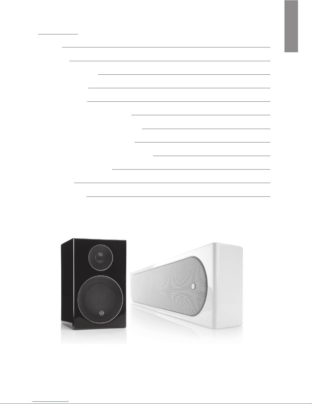
Radius One
The Radius One can be placed either just below or just above your TV/ projector screen. It
can be wall mounted with the supplied bracket (refer to page 5), or alternatively using the
Sanus VMA202 Soundbar Speaker Mount. refer to www.sanus.com for further information.
Radius 200
The Radius 200 is the range’s first dedicated centre speaker, and is designed to be placed
on a shelf or cabinet.
Radius Series
2
Page 5

monitoraudio.com
3
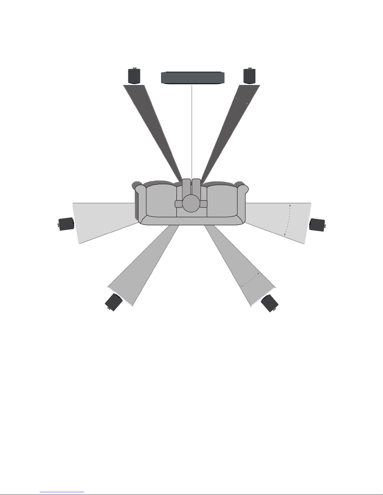
Positioning - Front Speakers
The centre channel should be the first speaker positioned in a home theatre room, and
such that the tweeter is directed towards the listener’s ear. The centre channel’s job is to
anchor dialogue and other on-screen sounds to the screen. Typically, as much as 60% of
a movie soundtrack comes through the centre channel.
The centre channel can be placed either above or below the TV screen, and as close as
possible. If positioned in a cabinet or sitting on top of the TV, ensure that the front edge
is aligned with the front edge of the TV or shelf. Where possible, the height of the centre
channels’ tweeter should be close to the height of the front speakers’ tweeter — ideally,
within about 600mm.
When placing Radius loudspeakers on the wall around a plasma/ LCD TV, the left and right
speakers need to be between 22 & 30° to the left and right of the seating position, with the
tweeters at approximate ear level.
Positioning - Surround Speakers
Ideally, the primary pair of surround speakers should be placed to the left and right of the
listening position — either in line with it, or just behind it (90 - 110°). If using a 6.1 or 7.1
channel system with more than two surround speakers, or if side placement isn’t available
in a 5.1 channel system, consider placement behind the listening position, facing the front
of the room (135 - 150°).
Surround speakers should be placed high enough so that the drivers do not fire directly at
ear level when sitting down — one rule of thumb is to place them at ear level while standing,
to avoid overpowering the front speakers.
If the surrounds are mounted on brackets on the side walls, experiment with aiming them.
Surround speaker placement ideal for home theatre, may not necessarily be so for
multichannel music listening, where a precisely focused rear soundstage is best. If both
types of listening are important, position them as a compromise between the two.
ENGLISH
Page 6
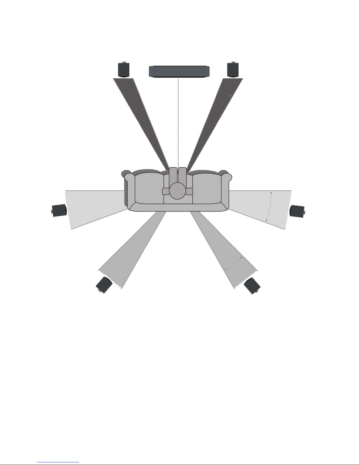
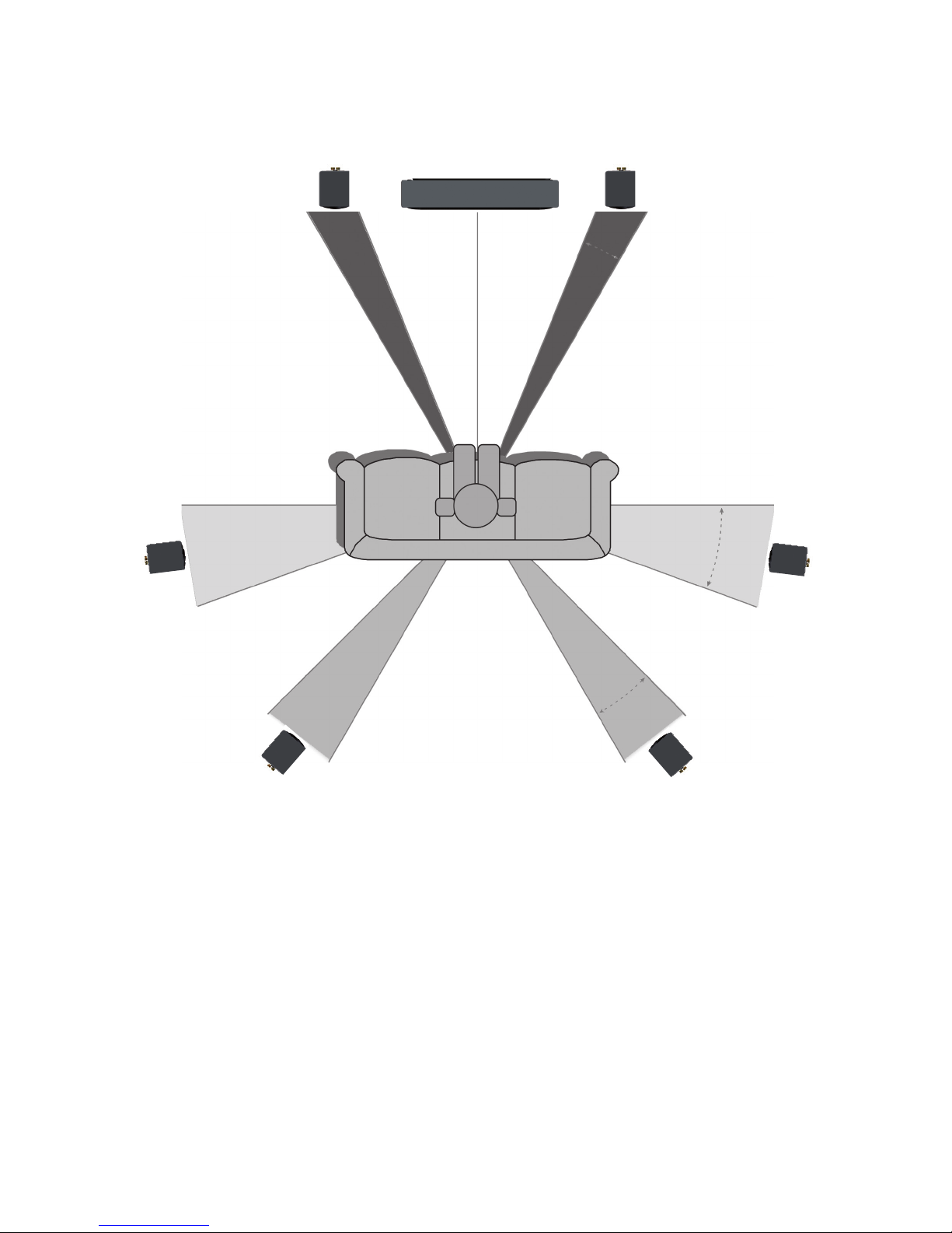
Optimum Speaker Placement
Radius Series
4
22°
0°
30°
90°
110°
135°
150°
Centre
Left Right
Surround
Right
Surround
Left
Rear
Surround
Left
Rear
Surround
Right
Page 7
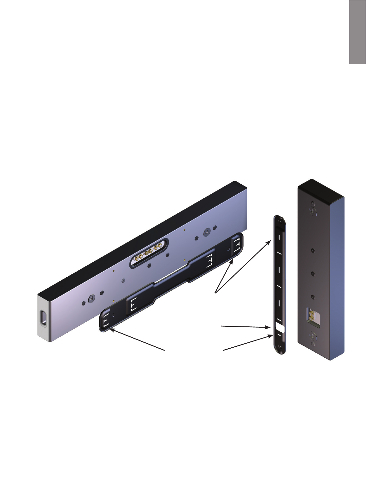
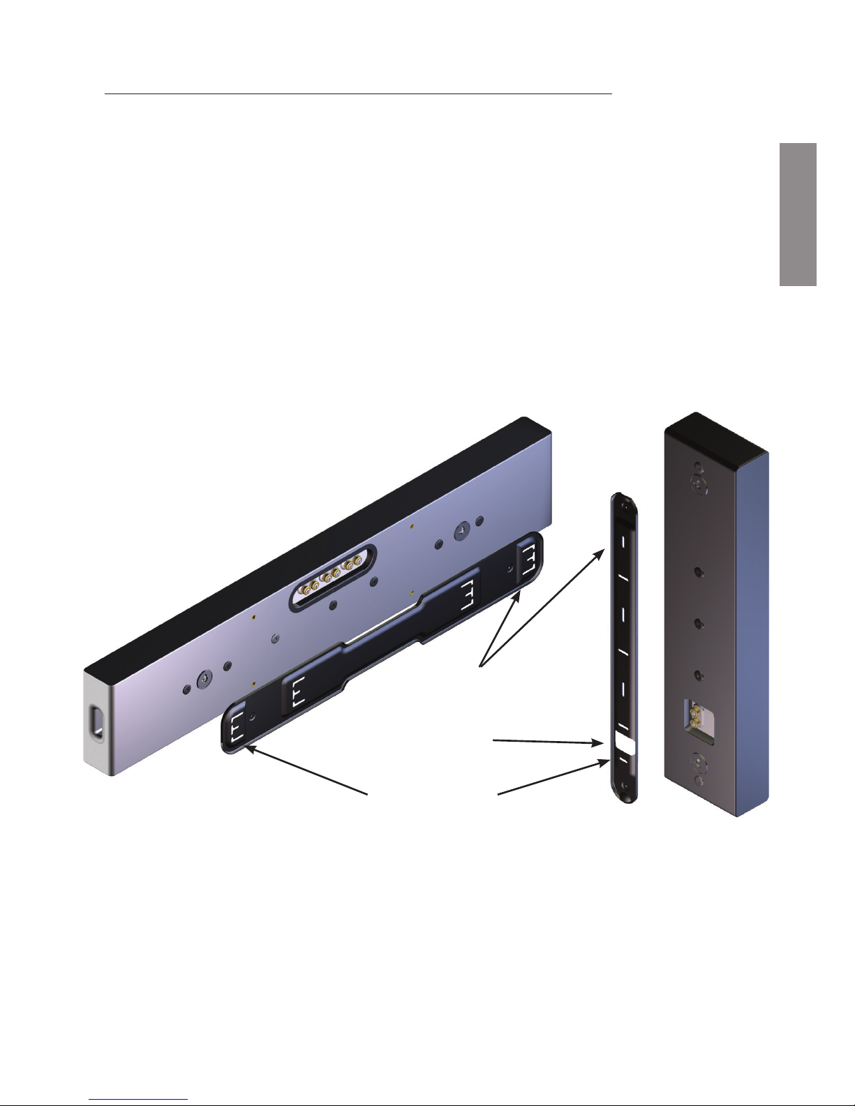
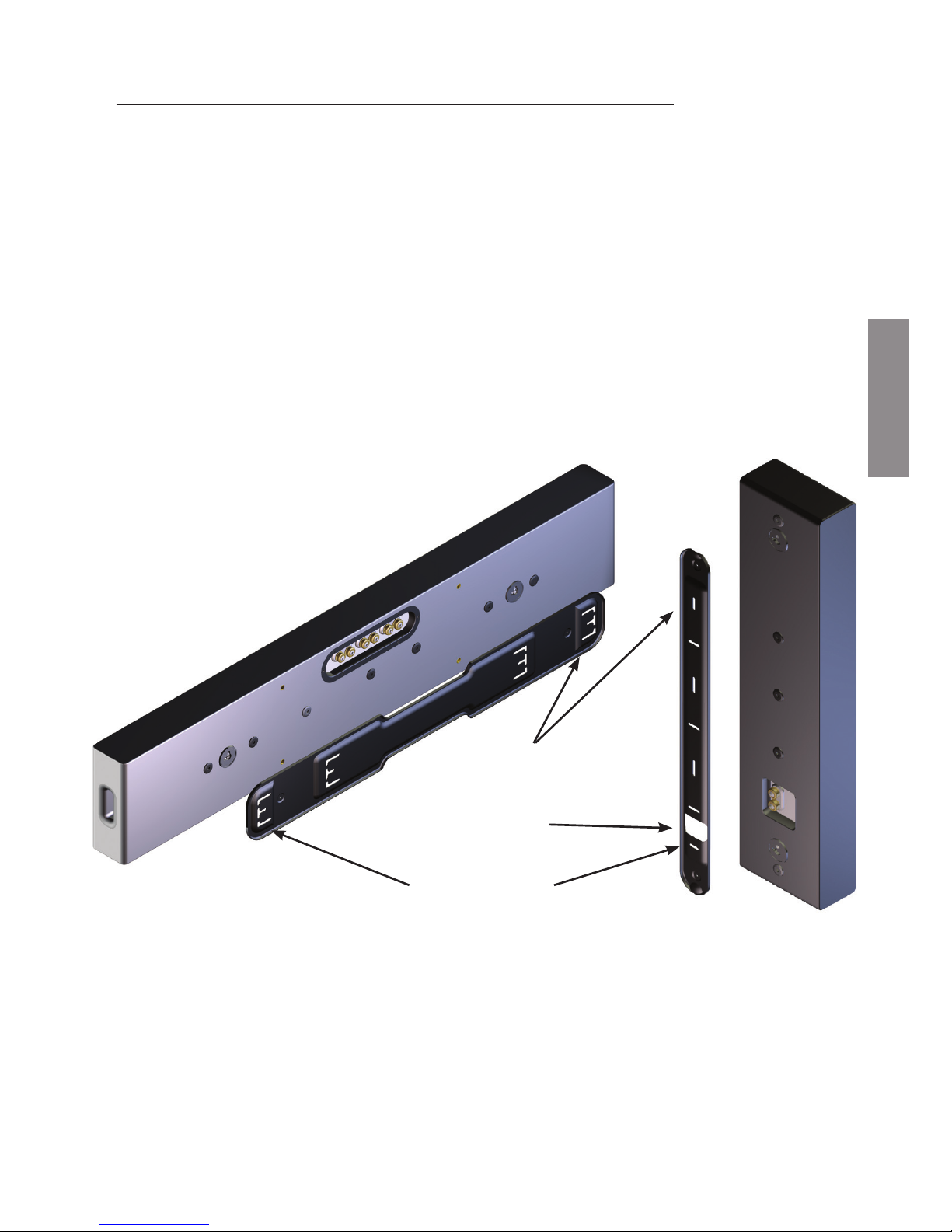
Fixing the Radius 225/ Radius One to a Wall
Additional Points to Remember
• When using the wall fixing plate, the speaker will drop by 7.5mm due to the key hole
fixing.
• Templates are supplied with the products to aid fixing.
• The Radius 225 grille badge can be rotated, simply by applying some pressure with
your thumb/ finger and turning.
• Please allow no more than 100mm (4 inches) of excess cable protruding from the wall.
Any excess cable can be coiled inside of the terminal panel.
• Please see the template for suggested rubber foot placement.
monitoraudio.com
5
Cable Through
Hole
Wall Mounting
Point
Wall Mounting
Point
ENGLISH
Page 8

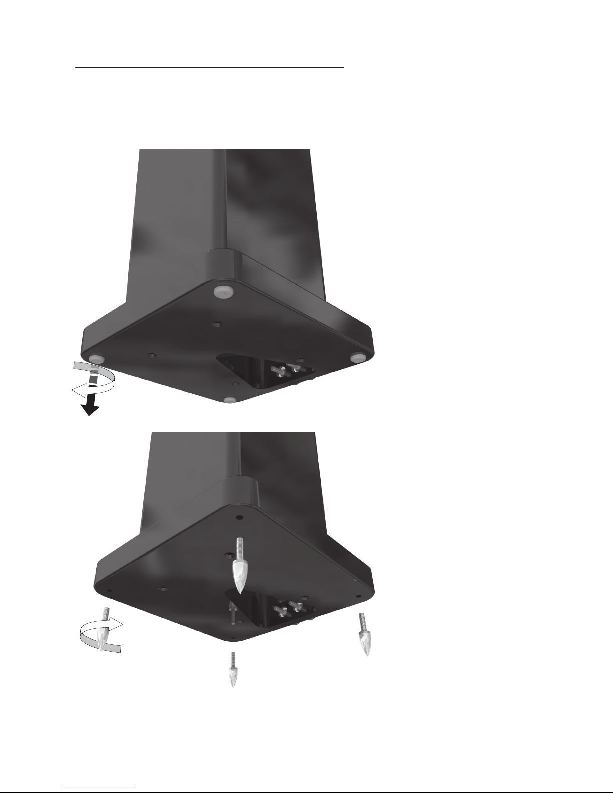
Radius 270 Feet and Spikes
The Radius 270 is supplied pre-installed with rubber feet for use on hard floors, or when
spikes are inappropriate.
If using spikes, first remove the
rubber feet by simultaneously
twisting and pulling them out,
revealing the threaded inserts.
Take the spikes and twist
them in a clockwise direction
in to the plinths. Ensure they
are fully inserted, stand the
cabinet up and place it in it’s
final location. To level, adjust
the spikes accordingly,
before finally tightening the
knurled locking nut to hold
the spikes in that position.
Radius Series
6
Page 9

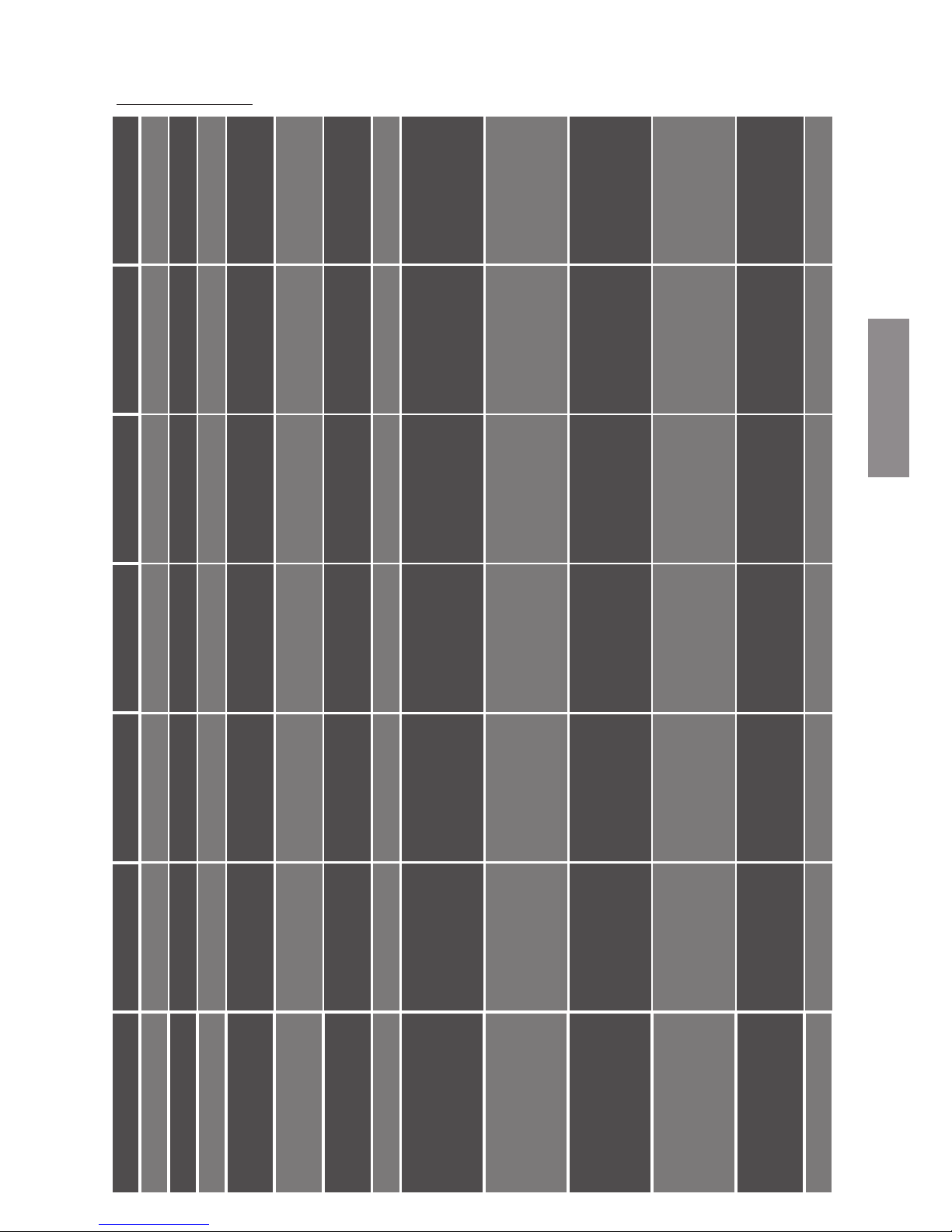
Specifications
Model Radius 45 Radius 90 Radius 200 Radius 225 Radius 270 Radius One
Frequency Response
120Hz – 20 KHz 80Hz – 35 KHz 60 Hz – 35 KHz 80Hz – 35KHz 50Hz – 35KHz 90Hz – 35KHz
Sensitivity (1W@1M)
87dB 83dB 86dB 87dB 87dB 87dB
Nominal Impedance
8 Ohms 8 Ohms 6 Ohms 6 Ohms 6 Ohm 6 Ohms
Power Handling
Single (RMS)
25W 75W 100W 100W 100W 75W
System Power
Handling (RMS)
50W 100W 100W 150W 150W 100W
Recommended Amp
Requirements
15-50 W 30-100 W 40-150W 40-150W 40-150W 30-100W
Maximum SPL (dBA)
101 105 105 108 108 108
Bass Alignment
Sealed Cabinet
Bass reflex –rear
ported
Bass reflex – rear
ported
Bass reflex – front
ported
Bass reflex – front &
rear ported
C: Bass reflex – front
ported
L/R: Bass reflex –
ported to sides
Drive Unit
Complement
1 x 3” MMP2 cone
mid-bass driver.
1 x 20mm C-CAM
gold dome tweeter
1 x 4” C-CAM cone
bass/ mid driver.
1 x 25mm C-CAM
gold dome tweeter
2 x 4” C-CAM cone
bass/ mid driver.
1 x 25mm C-CAM
gold dome tweeter
2 x 4” C-CAM cone
bass/ mid driver.
1 x 25mm C-CAM
gold dome tweeter
2 x 4” C-CAM cone
bass/ mid driver
1 x 25mm C-CAM
gold dome tweeter
3 x 4” C-CAM cone
bass/ mid driver.
3 x 25mm C-CAM
gold dome tweeter
Cabinet Dimensions
(H x W x D).
100 x 100 x 100mm
(3
15/16
x 3
15/16
x
3
15/16
")
198 x 125 x 140mm
(7
13/16
x 4
15/16
x 5
1/2
")
125 x 330 x 140mm
(4
15/16
x 13 x 5
1/2
")
610 x 140 x 67mm
(24 x 5
1/2
x 2
5/8
")
1000 x 177 x 208mm
(39
3/8
x 6
15/16
x 8
3/16
")
(Inc plinth without spikes)
175 x 980 x 67mm
(6
7/8
x 38
9/16
x 2
5/8
")
External Dimensions
Inc Grille and
Terminals. (H x W x D).
100 x 100 x 124mm
(3
15/16
x 3
15/16
x 4
7/8
")
198 x 125 x 165mm
(7
13/16
x 4
15/16
x 6
1/2
")
125 x 330 x 164mm
(4
15/16
x 13 x 6
7/16
")
610 x 140 x 77mm
(24 x 5
1/2
x 3
1/16
")
1025 x 177 x 208mm
(40
3/8
x 6
15/16
x 8
3/16
")
(Inc plinth with spikes)
175 x 980 x 79mm
(6
7/8
x 38
9/16
x 3
1/8
")
External Dimensions
Inc Grille Bracket.
(H x W x D).
100 x 100 x 162mm
(3
15/16
x 3
15/16
x 6
3/8
")
198 x 125 x 203mm
(7
13/16
x 4
15/16
x 8")
N/A
610 x 140 x 84mm
(24 x 5
1/2
x 3
5/16
")
N/A
175 x 980 x 84mm
(6
7/8
x 38
9/16
x 3
5/16
")
Weight (each)
Kg ( Ib)
1Kg (2lb 4oz) 2.1Kg (4lb 10oz) 3.6Kg (7lb 14oz) 4.2Kg (9lb 4oz) 9.9Kg (21lb 12oz) 7.4Kg (16lb 4oz)
Page 10

Owner Information
Product Details
Model .................................................................
Product Serial No ................................................
Date of Purchase ................................................
Dealer Details
Dealer Name .....................................................................................................................
Address .............................................................................................................................
...........................................................................................................................................
e-mail address ...................................................................................................................
Monitor Audio reserves the right to alter specifications without notice.
Radius Series
8
Page 11

Page 12

Manuel de l'utilisateur
series
Page 13
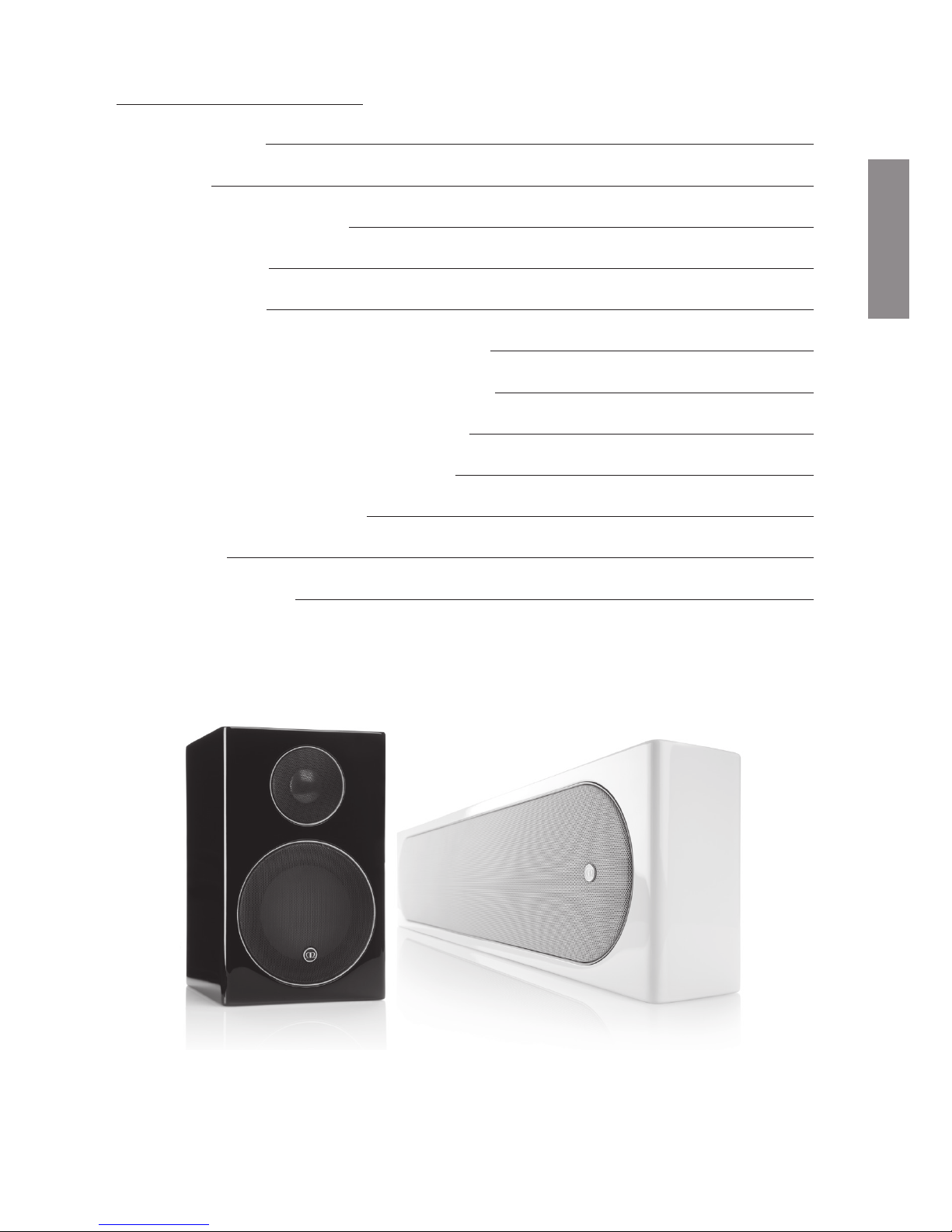
Table des matières
Table des matières 11
Introduction 12
Installation et positionnement 12
Radius One 12
Radius 200 12
Positionnement : haut-parleurs frontaux 13
Positionnement : haut-parleurs centraux 13
Placement optimal des haut-parleurs 14
Fixer le Radius 225 / Radius One à un mur 15
Pieds et pointes du Radius 270 16
Spécifications 17
Informations utilisateur 18
monitoraudio.com
11
FRANCAIS
Page 14

Introduction
Félicitations et merci de votre achat des haut-parleurs de la série Radius. Nous avons la
certitude qu'ils vous offriront des années de divertissement et de plaisir car nous n'avons
utilisé que des composants de haute qualité sur l'ensemble du produit.
Veuillez lire ce manuel de l'utilisateur attentivement car il contient des informations
importantes sur les procédures de positionnement et de configuration. Pour plus
d'informations avancées, veuillez consulter notre site Web : www.monitoraudio.com
Le Radius 45 incorpore un dispositif de protection thermique qui permet de
protéger l'unité de lecture et le tweeter de dégâts permanents. Si les haut-parleurs
cessent de fonctionner après une longue période de lecture, éteignez la source
pendant environ 10 minutes puis réessayez.
Installation et positionnement
Même si vous avez déjà réfléchi à la position et à la pertinence du produit avant l'achat
de ces haut-parleurs, cette section vous guidera pour obtenir une configuration et un
positionnement optimaux (une illustration est fournie en page 4 pour vous aider pour le
positionnement). Pour des instructions sur l'installation du Radius 225 ou du Radius One
sur un mur, reportez-vous à la page 5. Le Radius One propose des éléments de fixation
avec un support mural Sanus.
REMARQUE : Le Radius 45 et le Radius 90 peuvent être fixés à un mur avec notre support
de haut-parleur universel vendu séparément. Le Radius 200 n'est pas conçu pour être
monté sur un mur.
Des pieds en caoutchouc auto-adhésif sont fournis pour éviter les mouvements causés par
les vibrations lorsque les haut-parleurs de la série Radius sont sur une table / un support
d'équipement. Le Radius 270 est fourni avec des pieds en caoutchouc montés sur le socle
pour une utilisation sur les sols durs. Vous trouverez plus de détails à ce sujet en page 10.
Radius One
Le Radius One peut être placé juste en dessous ou juste au-dessus de votre TV / l'écran
de votre projecteur. Il peut être monté sur un mur avec le support fourni (voir page 5) ou
avec le support de haut-parleur Sanus VMA202 Soundbar, voir www.sanus.com pour plus
de détails.
Radius 200
Le Radius 200 est la première enceinte centrale dédiée de la série, et est conçu pour être
placé sur une étagère ou un meuble.
Série Radius
12
Page 15

monitoraudio.com
13
Positionnement : haut-parleurs frontaux
Le canal central doit être le premier haut-parleur positionné dans une salle de cinéma
maison, de sorte à ce que le tweeter soit orienté directement vers l'oreille de l'auditeur. La
tâche du canal central est d'ancrer à l'écran les dialogues et autres sons à l'écran. Souvent,
jusqu'à 60 % de la bande sonore d'un film provient du canal central.
Le canal central peut être placé soit au-dessus, soit en dessous de l'écran de télévision, et
aussi près que possible de celui-ci. S'il est placé sur un meuble ou sur le dessus de la TV,
assurez-vous que le bord avant est aligné avec le bord avant de la TV ou du meuble. Quand
cela est possible, la hauteur du tweeter des canaux centraux doit être proche de la hauteur
du tweeter des haut-parleurs frontaux : à moins de 600 mm idéalement.
Lorsque vous placez les haut-parleurs Radius sur le mur autour d'un écran plasma ou LCD,
les haut-parleurs gauche et droite doivent être entre 22 et 30 SDgr à gauche et à droite de
la position assise, avec les tweeters approximativement au niveau de l'oreille.
Positionnement : haut-parleurs centraux
Idéalement, la paire principale de haut-parleurs centraux doit être placée à gauche et à
droite de la position d'écoute : soit au même niveau, soit juste derrière (90 - 110 SDgr). Si
vous utilisez un système de canaux 6.1 ou 7.1 avec plus de deux haut-parleurs centraux,
ou si le placement latéral n'est pas disponible dans un système de canaux 5.1, considérez
un placement derrière la position d'écoute, en faisant face à la salle (135 - 150 SDgr).
Les haut-parleurs centraux doivent être placés suffisamment haut pour que les hautparleurs n'émettent pas de son directement au niveau des oreilles lorsque vous vous
asseyez : une règle générale est de les placer au niveau des oreilles lorsque vous vous
tenez debout, pour éviter de suralimenter les haut-parleurs frontaux.
Si les haut-parleurs centraux sont montés sur des supports sur les murs latéraux, essayez
de les orienter dans cette direction.
Le placement idéal des haut-parleurs centraux pour le cinéma maison ne l'est pas
forcément pour l'écoute de musique à canaux multiples, qui requiert idéalement un montage
du système sonore bien ajusté à l'arrière. Si les deux types d'écoute sont importants,
choisissez un compromis entre les deux pour le positionnement.
FRANCAIS
Page 16
Placement optimal des haut-parleurs
Série Radius
14
22°
0°
30°
90°
110°
135°
150°
Centre
Gauche
Surround
droite
Surround
arrière
gauche
Surround
arrière
droit
Surround
gauche
Droite
Page 17
Fixer le Radius 225 / Radius One à un mur
Points supplémentaires à garder en tête
• Lorsque vous utilisez la plaque de fixation murale, le haut-parleur s'abaissera de
7,5 mm en raison du trou de la fixation.
• Des modèles sont fournis avec les produits pour vous aider à les fixer.
• Pour pivoter le badge de la grille du Radius 225, appliquez simplement de la force avec
votre pouce/doigt et faites-le tourner.
• Ne laissez pas plus de 100 mm (4 pouces) de câble dépasser du mur. Tout câble
dépassant doit être enroulé autour du panneau du terminal.
• Voir le modèle pour le placement suggéré pour les pieds en caoutchouc.
monitoraudio.com
15
Câble à
travers le trou
Point de
montage mural
Point de
montage mural
FRANCAIS
Page 18
Pieds et pointes du Radius 270
Le Radius 270 est fourni préinstallé avec des pieds en caoutchouc pour une utilisation sur
des sols durs ou quand des pointes sont inappropriées.
Si vous utilisez des pointes,
retirez d'abord les pieds en
caoutchouc en les faisant
pivoter et en les faisant sortir
simultanément pour révéler les
inserts filetés.
Prenez les pointes et faitesles tourner dans le sens des
aiguilles d'une montre dans
le socle. Vérifiez qu'elles
sont bien insérées, relevez
le boîtier et installez-le à son
emplacement final. Pour
ajuster le niveau, réglez les
pointes en conséquence
avant de finalement serrer
l'écrou de verrouillage
moleté pour maintenir les
pointes dans cette position.
Série Radius
16
Page 19
Modèle Radius 45 Radius 90 Radius 200 Radius 225 Radius 270 Radius One
Réponse en fréquence
120 Hz – 20 KHz 80 Hz – 35 KHz 60 Hz – 35 KHz 80 Hz – 35 KHz 50 Hz – 35 KHz 90 Hz – 35 KHz
Sensibilité (1W@1M)
87 dB 83 dB 86 dB 87 dB 87 dB 87 dB
Impédance nominale
8 Ohms 8 Ohms 6 Ohms 6 Ohms 6 Ohms 6 Ohms
Gestion d'alimentation
simple (RMS)
25 W 75 W 100 W 100 W 100 W 75 W
Gestion d'alimentation
système (RMS)
50 W 100 W 100 W 150 W 150 W 100 W
Conditions conseillées pour
l'amplificateur
15-50 W 30-100 W 40-150 W 40-150 W 40-150 W 30-100 W
SPL maximum (dBA)
101 105 105 108 108 108
Alignement de la basse
Boîtier scellé
Bass-reflex porté vers
l'arrière
Bass-reflex porté vers
l'arrière
Bass-reflex porté vers
l'avant
Bass-reflex porté vers
l'avant et l'arrière
C : Bass-reflex porté vers
l'avant
G/D : Bass-reflex porté sur
les côtés
Complément d'unité
d'entraînement
Haut-parleur de graves
à cône 1 x 3” MMP2
Tweeter à dôme doré
1 x 20 mm C-CAM
Haut-parleur de graves
à cône 1 x 4” C-CAM
Tweeter à dôme doré
1 x 25 mm C-CAM
Haut-parleur de graves
à cône 2 x 4 ” C-CAM
Tweeter à dôme doré
1 x 25 mm C-CAM
Haut-parleur de graves
à cône 2 x 4 ” C-CAM
Tweeter à dôme doré
1 x 25 mm C-CAM
Haut-parleur de graves
à cône 2 x 4 ” C-CAM
Tweeter à dôme doré
1 x 25 mm C-CAM
Haut-parleur de graves
à cône 3 x 4 ” C-CAM
Tweeter à dôme doré
3 x 25 mm C-CAM
Dimensions du boîtier
(H x L x P)
100 x 100 x 100 mm
(3
15/16
x 3
15/16
x 3
15/16
")
198 x 125 x 140 mm
(7
13/16
x 4
15/16
x 5
1/2
pouces)
125 x 330 x 140 mm
(4
15/16
x 13 x 5
1/2
pouces)
610 x 140 x 67 mm
(24 x 5
1/2
x 2
5/8
pouces)
1 000 x 177 x 208 mm
(39
3/8
x 6
15/16
x 8
3/16
pouces)
(Socle intégré sans pointes)
175 x 980 x 67 mm
(6
7/8
x 38
9/16
x 2
5/8
pouces)
Dimensions externes de
la grille et des terminaux
intégrés. (H x L x P)
100 x 100 x 124 mm
(3
15/16
x 3
15/16
x 4
7/8
pouces)
198 x 125 x 165 mm
(7
13/16
x 4
15/16
x 6
1/2
pouces)
125 x 330 x 164 mm
(4
15/16
x 13 x 6
7/16
pouces)
610 x 140 x 77 mm
(24 x 5
1/2
x 3
1/16
pouces)
1025 x 177 x 208 mm
(40
3/8
x 6
15/16
x 8
3/16
pouces)
(Socle intégré avec pointes)
175 x 980 x 79 mm
(6
7/8
x 38
9/16
x 3
1/8
pouces)
Dimensions externes du
support de la grille.
(H x L x P)
100 x 100 x 162 mm
(3
15/16
x 3
15/16
x 6
3/8
pouces)
198 x 125 x 203 mm
(7
13/16
x 4
15/16
x 8 pouces)
N/D
610 x 140 x 84 mm
(24 x 5
1/2
x 3
5/16
pouces)
N/D
175 x 980 x 84 mm
(6
7/8
x 38
9/16
x 3
5/16
pouces)
Poids (pour chaque) Kg ( Ib)
1 Kg (2 lb 4 oz) 2.,1 Kg (4lb 10oz) 3,6 Kg (7lb 14oz) 4,2 Kg (9 lb 4 oz) 9,9 Kg (21 lb 12 oz) 7,4 Kg (16 lb 4 oz)
Spécifications
Page 20

Informations utilisateur
Détails du produit
Modèle .................................................................
Numéro de série du produit ................................................
Date d'achat ................................................
Informations du revendeur
Nom du revendeur ............................................................................................................
Adresse ............................................................................................................................
...........................................................................................................................................
Adresse e-mail ..................................................................................................................
Monitor Audio se réserve le droit de modifier les spécifications sans notification préalable.
Série Radius
18
Page 21

FRANCAIS
Page 22

Manuale utente
series
Page 23

ITALIANO
Sommario
Sommario 21
Introduzione 22
Installazione e posizionamento 22
Radius One 22
Radius 200 22
Posizionamento - Altoparlanti anteriori 23
Posizionamento - Altoparlanti surround 23
Posizionamento ottimale degli altoparlanti 24
Installare Radius 225/Radius One a parete 25
Radius 270: piedini e punte 26
Specifiche 27
Informazioni per l'utente 28
monitoraudio.com
21
Page 24
Introduzione
Congratulazioni e grazie per aver acquistato gli altoparlanti della serie Radius, realizzati con
componenti di altissima qualità, per garantire piacere di ascolto e affidabilità duraturi nel
tempo.
Consigliamo di seguire attentamente questo manuale utente, perché contiene informazioni
importanti sul posizionamento e sulle procedure di installazione. Per informazioni più
approfondite, consultare il nostro sito web alla pagina: www.monitoraudio.com
Radius 45 integra un dispositivo di protezione termica che aiuta a proteggere l'unità
drive e il tweeter da danni permanenti. Se l'altoparlante smette di funzionare dopo
un utilizzo prolungato, spegnere la sorgente per circa 10 minuti, quindi riprovare.
Installazione e posizionamento
Anche se la collocazione e l'adeguatezza degli altoparlanti saranno state valutate prima
dell'acquisto, questa sezione fornisce istruzioni per un posizionamento e un'installazione
ottimali (per il posizionamento, consultare l'illustrazione a pagina 4). Per istruzioni sul
montaggio a parete di Radius 225 o Radius One, fare riferimento a pagina 5. I dispositivi di
fissaggio di Radius One sono compatibili con la staffa da parete Sanus.
NOTA BENE: Radius 45 e 90 si possono installare a parete utilizzando il nostro sistema
di montaggio universale per altoparlanti, in vendita separatamente. Radius 200 non è
progettato per il montaggio a parete.
Sono inclusi piedini in gomma autoadesivi che impediscono lo spostamento causato
da vibrazioni, quando gli altoparlanti della serie Radius vengono usati su un tavolo o un
mobiletto. Radius 270 viene fornito completo di piedini in gomma inseriti nella base, da
utilizzare su superfici dure. Maggiori dettagli si trovano a pagina 10.
Radius One
Radius One può essere sistemato appena sotto o sopra il televisore o lo schermo del
proiettore. Si può installare a parete con la staffa in dotazione (fare riferimento a pagina 5) o
in alternativa utilizzando il sistema di montaggio per altoparlanti Sanus VMA202 Soundbar
(visitare www.sanus.com per maggiori informazioni).
Radius 200
Radius 200 è il primo altoparlante centrale dedicato della gamma, progettato per essere
collocato su una mensola o un mobiletto.
Serie Radius
22
Page 25

monitoraudio.com
23
Posizionamento - Altoparlanti anteriori
Il canale centrale va posizionato per primo all'interno della stanza home theater, e in modo
che il tweeter sia diretto verso l'orecchio di chi ascolta. La funzione del canale centrale è di
ancorare dialoghi e altri suoni allo schermo. Solitamente, fino al 60% della colonna sonora
di un film viene riprodotto dal canale centrale.
Il canale centrale si può collocare sopra o sotto lo schermo della TV, il più vicino possibile.
Se posizionato in un mobiletto o appoggiato sulla TV, assicurarsi che il bordo anteriore
sia allineato al bordo anteriore del televisore o della mensola. Dove possibile, l'altezza del
tweeter dei canali centrali dovrebbe avvicinarsi all'altezza del tweeter degli altoparlanti
anteriori, idealmente entro circa 600 mm.
Quando si installano gli altoparlanti Radius sulla parete accanto a una TV al plasma/LCD,
le unità sinistra e destra devono essere collocate a 22 - 30º a sinistra e a destra del posto
in cui lo spettatore si siederà, con i tweeter approssimativamente all'altezza dell'orecchio.
Posizionamento - Altoparlanti surround
Idealmente, la coppia principale di altoparlanti surround andrebbe sistemata a sinistra e a
destra del posto a sedere, in linea con lo spettatore o appena più indietro (90 - 110º). Se si
usa un sistema 6.1 o 7.1 con più di due altoparlanti surround, o se si usa un sistema 5.1
ma il posizionamento laterale non è possibile, si può optare per una collocazione dietro la
posizione di ascolto, con le unità rivolte verso la parte anteriore della stanza (135 - 150º).
Gli altoparlanti surround andrebbero posizionati abbastanza in alto da far sì che i driver
non siano direttamente all'altezza dell'orecchio dello spettatore seduto; come regola, è
bene installarli all'altezza dell'orecchio dello spettatore in piedi per evitare di sovraccaricare
l'audio degli altoparlanti anteriori.
Se i surround sono installati su staffe sulle pareti laterali, provare a orientarli in modi diversi.
Non è detto che il posizionamento ideale di un altoparlante surround per l'home theater sia
adatto anche per l'ascolto di musica multicanale, che richiede invece un ambiente sonoro
posteriore, centrato con estrema precisione. Se entrambi i tipi di ascolto sono importanti,
optare per un compromesso fra i due tipi di posizionamento.
ITALIANO
Page 26
Posizionamento ottimale degli altoparlanti
Serie Radius
24
22°
0°
30°
90°
110°
135°
150°
Centrale
Sinistro Destro
Surround
destro
Surround
sinistro
Surround
posteriore
sinistro
Surround
posteriore
destro
Page 27
Installare Radius 225/Radius One a parete
Altri punti da ricordare
• Quando si usa la piastra per il montaggio sulla parete, l'altoparlante si abbasserà di 7,5
mm a causa del sistema di fissaggio ad asola.
• I prodotti sono accompagnati da modelli per facilitare il fissaggio.
• Il badge sulla griglia di Radius 225 può essere ruotato: basta premere con il pollice o
con un dito e girarlo.
• Il cavo in uscita dalla parete non dovrebbe essere più lungo di 100 mm. L'eventuale
cavo in eccesso può essere arrotolato all'interno del pannello del terminale.
• Fare riferimento al modello per il posizionamento consigliato del piedino in gomma.
monitoraudio.com
25
Foro passacavo
Punto di montaggio
a parete
Punto di montaggio
a parete
ITALIANO
Page 28

Radius 270: piedini e punte
Su Radius 270 sono preinstallati dei piedini in gomma da utilizzare sulle superfici dure, o
quando le punte non sono adatte.
Se si usano le punte, prima
rimuovere i piedini ruotandoli e
tirandoli contemporaneamente
per scoprire gli inserti filettati.
Prendere le punte e inserirle
nei basamenti girandole in
senso orario. Assicurarsi che
siano inserite completamente,
quindi raddrizzare la cassa
e sistemarla nella sua
collocazione finale. Per
livellare l'altoparlante,
regolare le punte secondo
necessità, prima di
stringere il dado zigrinato
che le bloccherà in
posizione.
Serie Radius
26
Page 29
Modello
Radius 45 Radius 90 Radius 200 Radius 225 Radius 270 Radius One
Risposta in frequenza
120 Hz – 20 KHz 80 Hz – 35 KHz 60 Hz – 35 KHz 80 Hz – 35 KHz 50 Hz – 35 KHz 90 Hz – 35 KHz
Sensibilità (1W@1M)
87 dB 83 dB 86 dB 87 dB 87 dB 87 dB
Impedenza nominale
8 Ohm 8 Ohm 6 Ohm 6 Ohm 6 Ohm 6 Ohm
Tenuta di potenza singola
unità (RMS)
25 W 75 W 100 W 100 W 100 W 75 W
Tenuta di potenza sistema
(RMS)
50 W 100 W 100 W 150 W 150 W 100 W
Requisiti consigliati
amplificatore
15-50 W 30-100 W 40-150 W 40-150 W 40-150 W 30-100 W
SPL massimo (dBA)
101 105 105 108 108 108
Allineamento bassi
Cassa chiusa
Apertura bass reflex
posteriore
Apertura bass reflex
posteriore
Apertura bass reflex
anteriore
Apertura bass reflex
anteriore e posteriore
C: Apertura bass reflex
anteriore
L/R: Aperture bass reflex
laterali
Complemento unità drive
1 x 3” MMP2 Cone Mid-
bass Driver. 1 x 20 mm
C-CAM Gold
Dome Tweeter
1 x 4” C-CAM Cone Bass/
Mid Driver. 1 x 25 mm
C-CAM Gold
Dome Tweeter
2 x 4” C-CAM Cone Bass/
Mid Driver. 1 x 25 mm
C-CAM Gold
Dome Tweeter
2 x 4” C-CAM Cone Bass/
Mid Driver. 1 x 25 mm
C-CAM Gold
Dome Tweeter
2 x 4” C-CAM Cone Bass/
Mid Driver 1 x 25 mm
C-CAM Gold
Dome Tweeter
3 x 4” C-CAM Cone Bass/
Mid Driver. 3 x 25 mm
C-CAM Gold
Dome Tweeter
Dimensioni cassa
(H x W x D).
100 x 100 x 100 mm
(3
15/16
x 3
15/16
x 3
15/16
")
198 x 125 x 140 mm
(7
13/16
x 4
15/16
x 5
1/2
")
125 x 330 x 140 mm
(4
15/16
x 13 x 5
1/2
")
610 x 140 x 67 mm
(24 x 5
1/2
x 2
5/8
")
1000 x 177 x 208 mm
(39
3/8
x 6
15/16
x 8
3/16
")
(incluso basamento
senza punte)
175 x 980 x 67 mm
(6
7/8
x 38
9/16
x 2
5/8
")
Dimensioni esterne inclusi
griglie e terminali
(H x W x D).
100 x 100 x 124 mm
(3
15/16
x 3
15/16
x 4
7/8
")
198 x 125 x 165 mm
(7
13/16
x 4
15/16
x 6
1/2
")
125 x 330 x 164 mm
(4
15/16
x 13 x 6
7/16
")
610 x 140 x 77 mm
(24 x 5
1/2
x 3
1/16
")
1025 x 177 x 208 mm
(40
3/8
x 6
15/16
x 8
3/16
")
(incluso basamento
senza punte)
175 x 980 x 79 mm
(6
7/8
x 38
9/16
x 3
1/8
")
Dimensioni esterne
inclusa griglia.
(H x W x D).
100 x 100 x 162 mm
(3
15/16
x 3
15/16
x 6
3/8
")
198 x 125 x 203 mm
(7
13/16
x 4
15/16
x 8")
N/D
610 x 140 x 84 mm
(24 x 5
1/2
x 3
5/16
")
N/D
175 x 980 x 84 mm
(6
7/8
x 38
9/16
x 3
5/16
")
Peso (ciascuno) Kg (lb)
1 Kg (2 lb 4 oz) 2,1 Kg (4 lb 10 oz) 3,6 Kg (7 lb 14 oz) 4,2 Kg (9 lb 4 oz) 9,9 Kg (21 lb 12 oz) 7,4 Kg (16 lb 4 oz)
Specifiche
ITALIANO
Page 30

Informazioni per l'utente
Dettagli prodotto
Modello .................................................................
Num. di serie prodotto …………………………………..
Data di acquisto ……………………………………
Informazioni rivenditore
Nome rivenditore ...............................................................................................................
Indirizzo ............................................................................................................................
...........................................................................................................................................
Indirizzo e-mail ..................................................................................................................
Monitor Audio si riserva il diritto di modificare le specifiche senza preavviso.
Serie Radius
28
Page 31

ITALIANO
Page 32

Bedienungsanleitung
series
Page 33

DEUTSCH
Inhalt
Inhalt 31
Einführung 32
Einstellung und Aufstellung 32
Radius One 32
Radius 200 32
Aufstellung - Front-Lautsprecher 33
Aufstellung - Surround-Lautsprecher 33
Optimale Lautsprecheraufstellung 34
Wandbefestigung des Radius 225 / Radius One 35
Radius 270 – Füße und Stifte 36
Technische Daten 37
Eigentümerinformationen 38
monitoraudio.com
31
Page 34

Einführung
Wir gratulieren und danken Ihnen für den Kauf der Lautsprecher der Radius-Serie.
Diese Lautsprecher werden Ihnen jahrelang Freude und Unterhaltung bereiten, denn wir
verwenden in jeder Produktionsphase ausschließlich Bauteile höchster Qualität.
Bitte befolgen Sie diese Bedienungsanleitung sorgfältig. Sie enthält wichtige Informationen
über die Auf- und Einstellung. Weitere und ausführlichere Informationen finden Sie auf
unserer Website: www.monitoraudio.com
Der Radius 45 ist mit einer Thermoschutz-Vorrichtung ausgestattet. Diese schützt
die Antriebseinheit und den Hochtöner vor dauerhafter Beschädigung. Sobald
sich der Lautsprecher nach einer längeren Betriebsdauer abschaltet, sollten Sie
die Quelle etwa zehn Minuten lang abschalten und es danach erneut versuchen.
Einstellung und Aufstellung
Obwohl die Positionierung und die Eignung schon vor dem Kauf der Lautsprecher
berücksichtigt wurde, gibt dieser Abschnitt eine Anleitung zur Aufstellung und Einstellung
(auf Seite 4 finden Sie eine Abbildung, die Ihnen bei der Aufstellung helfen kann). Auf
Seite 5 finden Sie eine Anleitung zur Wandmontage der Lautsprecher Radius 225 oder
Radius One. Radius One ist mit Befestigungselementen ausgestattet, die mit einer SanusWandhalterung kompatibel sind.
HINWEIS: Die Lautsprecher Radius 45 und 90 können mit unserer separat erhältlichen
Universal-Lautsprecherhalterung an der Wand befestigt werden. Der Radius 200 ist nicht
für die Wandmontage konzipiert.
Die Ausstattung umfasst selbstklebende Gummifüße, die Bewegungen aufgrund von
Vibrationen verhindern, wenn der Lautsprecher auf einem Tisch oder einem Ständer
aufgestellt wird. Die Ausstattung des Radius 270 umfasst Gummifüße im Sockel für die
Verwendung auf harten Oberflächen. Weitere Einzelheiten darüber finden Sie auf Seite 10.
Radius One
Der Radius One kann entweder direkt unter oder direkt über dem Fernseher / der
Leinwand platziert werden. Mit der beiliegenden Halterung ist auch eine Wandmontage
möglich (lesen Sie dazu Seite 5). Alternativ verwenden Sie die Sanus-VMA202-SoundbarLautsprecherhalterung. Weitere Informationen darüber finden Sie auf www.sanus.com.
Radius 200
Der Radius 200 ist der erste eigens entwickelte Center-Lautsprecher der Reihe für eine
Aufstellung im Regal oder Schrank.
Radius-Serie
32
Page 35

DEUTSCH
monitoraudio.com
33
Aufstellung - Front-Lautsprecher
In einem Heimkino sollte der Center-Kanal als erstes aufgestellt werden, wobei der
Hochtöner direkt auf die Ohren des Hörers ausgerichtet sein sollte. Der Center-Kanal soll
die Dialoge und andere sichtbare Geräusche auf dem Bildschirm fixieren. Gewöhnlich
werden etwa 60 % der Filmmusik über den Center-Kanal wiedergegeben.
Der Center-Kanal kann entweder über oder unter dem Fernseher platziert werden, wobei der
Abstand möglichst gering gehalten werden sollte. Erfolgt die Aufstellung in einem Schrank
oder über dem Fernseher, so sollte die Vorderkante auf die Kante des Fernsehers oder
Schranks ausgerichtet werden. Idealerweise sollte die Höhe des Hochtöners des CenterKanals möglichst mit der Höhe der Hochtöner der Front-Lautsprecher übereinstimmen –
perfekt wäre eine Abweichung von maximal 600 mm.
Bei einer Wandmontage der Radius-Lautsprecher um einen Plasma- oder LCD-Fernseher
müssen die rechten und linken Lautsprecher zwischen 22 und 30 SDgr zur Rechten und
Linken der Sitzposition liegen, wobei sich die Hochtöner etwa auf Ohrhöhe befinden sollten.
Aufstellung - Surround-Lautsprecher
Die beiden Surround-Lautsprecher sollten idealerweise links und rechts von der Sitzposition
aufgestellt werden – entweder in einer Linie oder direkt dahinter (90 - 110 SDgr). Bei
einem 6.1- oder 7.1-Kanalsystem mit mehr als zwei Surround-Lautsprechern – oder wenn
bei einem 5.1-Kanalsystem keine Platzierung an den Seiten möglich ist – stellen Sie die
Lautsprecher hinter der Hörposition auf und richten Sie sie nach vorne in den Raum (135
- 150 SDgr).
Die Aufstellung der Surround-Lautsprecher sollte hoch genug erfolgen, damit die
Lautsprecherfrequenzgänge beim Sitzen nicht direkt in Ohrhöhe ausstrahlen – ein
praktischer Erfahrungswert ist die Platzierung in Ohrhöhe im Stehen, damit die FrontLautsprecher nicht überlagert werden.
Wenn die Surround-Lautsprecher mit einer Halterung an der Wand befestigt werden, sollten
Sie bei der Aufstellung ein wenig experimentieren.
Die Aufstellung der Surround-Lautsprecher, die sich für ein Heimkino eignet, ist beim
Musikgenuss mit mehreren Kanälen vielleicht nicht ideal. Dabei wird ein genau ausgerichtetes
hinteres Panorama bevorzugt. Wenn Sie auf beide Hörarten Wert legen, sollten Sie bei der
Aufstellung einen Kompromiss eingehen.
Page 36

Optimale Lautsprecheraufstellung
Radius-Serie
34
22°
0°
30°
90°
110°
135°
150°
Center
Links Rechts
Surround
Rechts
Surround
Links
Surround
Hinten
Links
Surround
Hinten
Rechts
Page 37

DEUTSCH
Wandbefestigung des Radius 225 / Radius One
Weitere Hinweise
• Bei einer Montageplatte zur Wandbefestigung liegt der Lautsprecher aufgrund der
Schlüsselloch-Befestigungsart um 7,5 mm tiefer.
• Für eine bessere Befestigung liegen den Produkten Schablonen bei.
• Die Gitterplakette des Radius 225 lässt sich einfach mit etwas Druck Ihres Daumen /
Fingers drehen.
• Aus der Wand sollten nicht mehr als 100 mm (4 Zoll) überschüssiges Kabel hängen.
Das überschüssige Kabel kann im Anschlussfeld aufgerollt werden.
• Für die empfohlene Gummifuß-Platzierung nehmen Sie die Vorlage zu Hilfe.
monitoraudio.com
35
Kabel-
Durchgangsbohrung
Punkt zur
Wandbefestigung
Punkt zur
Wandbefestigung
Page 38

Radius 270 – Füße und Stifte
Die Auslieferung des Radius 270 erfolgt mit bereits vormontierten Gummifüßen für harten
Untergrund – oder wenn Stifte unangebracht wären.
Bei der Verwendung von
Stiften müssen die Gummifüße
erst entfernt werden, indem Sie
diese gleichzeitig drehen und
herausziehen. Danach liegen
die Gewindeeinsätze frei.
Nehmen Sie die Stifte
und drehen Sie diese im
Uhrzeigersinn in die Sockel.
Prüfen Sie den festen Sitz,
stellen Sie das Gehäuse
auf und platzieren Sie
es am endgültigen
Standort. Für eine ebene
Ausrichtung passen Sie
die Stifte entsprechend
an, ehe Sie die RändelSicherungsmutter
festziehen, um die Stifte
in der entsprechenden
Position zu halten.
Radius-Serie
36
Page 39

DEUTSCH
Modell
Radius 45 Radius 90 Radius 200 Radius 225 Radius 270 Radius One
Frequenzbereich
120 Hz – 20 KHz 80 Hz – 35 KHz 60 Hz – 35 KHz 80 Hz – 35 KHz 50 Hz – 35 KHz 90 Hz – 35 KHz
Empfindlichkeit (1 W bei 1 M)
87 dB 83 dB 86 dB 87 dB 87 dB 87 dB
Nennimpedanz
8 Ohm 8 Ohm 6 Ohm 6 Ohm 6 Ohm 6 Ohm
Leistungsfähigkeit einzeln
(Effektivspannung)
25 W 75 W 100 W 100 W 100 W 75 W
Leistungsfähigkeit des
Systems (Effektivspannung)
50 W 100 W 100 W 150 W 150 W 100 W
Empfohlene Verstärker-
Anforderungen
15-50 W 30-100 W 40-150 W 40-150 W 40-150 W 30-100 W
Max. Schalldruckpegel (dBA)
101 105 105 108 108 108
Bassanpassung
Versiegeltes Gehäuse Rückseitiges Bassreflexrohr Rückseitiges Bassreflexrohr
Vorderseitiges
Bassreflexrohr
Vorder- und rückseitiges
Bassreflexrohr
C: Vorderseitiges
Bassreflexrohr
L/R: Seitliches
Bassreflexrohr
Ergänzung der
Antriebseinheit
1 x 3”-MMP2-
Konusmitteltieftöner
1 x 20-mm-C-CAM-
Goldhochtöner
1 x 4”-C-CAM-
Konustieftöner/Mitteltöner.
1 x 25-mm-C-CAM-
Goldhochtöner
2 x 4”-C-CAM-
Konustieftöner/Mitteltöner.
1 x 25-mm-C-CAM-
Goldhochtöner
2 x 4”-C-CAM-
Konustieftöner/Mitteltöner.
1 x 25-mm-C-CAM-
Goldhochtöner
2 x 4”-C-CAM-
Konustieftöner/Mitteltöner
1 x 25mm C-CAM-
Goldhochtöner
3 x 4”-C-CAM-
Konustieftöner/Mitteltöner.
3 x 25-mm-C-CAM-
Goldhochtöner
Gehäuseabmessungen
(H x B x T)
100 x 100 x 100 mm
(3
15/16
x 3
15/16
x 3
15/16
")
198 x 125 x 140 mm
(7
13/16
x 4
15/16
x 5
1/2
")
125 x 330 x 140 mm
(4
15/16
x 13 x 5
1/2
")
610 x 140 x 67 mm
(24 x 5
1/2
x 2
5/8
")
1000 x 177 x 208 mm
(39
3/8
x 6
15/16
x 8
3/16
")
(Inkl. Sockel ohne Stifte)
175 x 980 x 67 mm
(6
7/8
x 38
9/16
x 2
5/8
")
Außenabmessungen inkl.
Gitter und Anschlüssen.
(H x B x T)
100 x 100 x 124 mm
(3
15/16
x 3
15/16
x 4
7/8
")
198 x 125 x 165 mm
(7
13/16
x 4
15/16
x 6
1/2
")
125 x 330 x 164 mm
(4
15/16
x 13 x 6
7/16
")
610 x 140 x 77 mm
(24 x 5
1/2
x 3
1/16
")
1025 x 177 x 208 mm
(40
3/8
x 6
15/16
x 8
3/16
")
(Inkl. Sockel mit Stiften)
175 x 980 x 79 mm
(6
7/8
x 38
9/16
x 3
1/8
")
Außenabmessungen inkl.
Gitterhalterung. (H x B x T)
100 x 100 x 162 mm
(3
15/16
x 3
15/16
x 6
3/8
")
198 x 125 x 203 mm
(7
13/16
x 4
15/16
x 8")
k. A.
610 x 140 x 84 mm (24 x 5
1/2
x 3
5/16
")
k. A.
175 x 980 x 84 mm
(6
7/8
x 38
9/16
x 3
5/16
")
Gewicht (jeweils) kg (Ib)
1 kg (2 lb 4 oz) 2,1 kg (4 lb 10 oz) 3,6 kg (7 lb 14 oz) 4,2 kg (9 lb 4 oz) 9,9 kg (21 lb 12 oz) 7,4 kg (16 lb 4 oz)
Technische Daten
Page 40

Eigentümerinformationen
Produktangaben
Modell .................................................................
Produkt-Seriennummer ................................................
Kaufdatum ................................................
Händlerinformationen
Händlername ....................................................................................................................
Adresse ............................................................................................................................
...........................................................................................................................................
E-Mail-Adresse .................................................................................................................
Monitor Audio behält sich das Recht vor, die technischen Daten ohne vorherige Ankündigung
zu ändern.
Radius-Serie
38
Page 41

DEUTSCH
Page 42

Manual de usuario
series
Page 43

ESPAÑOL
Índice
Índice 41
Introducción 42
Configuración y posicionamiento 42
Radius One 42
Radius 200 42
Posicionamiento - Altavoces frontales 43
Posicionamiento - Altavoces envolventes 43
Posicionamiento óptimo de los altavoces 44
Fijación del Radius 225 / Radius One a la pared 45
Pies y puntas de desacoplo del Radius 270 46
Especificaciones 47
Información del usuario 48
monitoraudio.com
41
Page 44

Introducción
Enhorabuena y gracias por adquirir estos altavoces de la serie Radius. Para su fabricación
se han utilizado exclusivamente componentes de la más alta calidad, por lo que estamos
seguros de que le proporcionaran años de disfrute y diversión.
Siga las instrucciones del manual de usuario detenidamente, ya que contienen información
importante acerca de los procedimientos de posicionamiento y configuración. Si desea
información avanzada, visite nuestra página web: www.monitoraudio.com
El Radius 45 incorpora un dispositivo termoprotector que ayuda a proteger el
transductor y el tweeter de daños permanentes. Si el altavoz deja de funcionar
tras reproducir música durante un periodo prolongado, desconecte la fuente
durante unos 10 minutos y pruebe de nuevo.
Configuración y posicionamiento
Aunque antes de adquirir estos altavoces habrá tenido en cuenta la idoneidad y la posición,
este apartado le ayudará a encontrar una configuración y un posicionamiento óptimos (en
la página 4 se facilita una ilustración que le asistirá en el posicionamiento del dispositivo). En
la página 5 encontrará instrucciones para el montaje en pared del Radius 225 o el Radius
One. El Radius One cuenta con fijaciones compatibles con un soporte de pared Sanus.
NOTA: los Radius 45 y 90 pueden montarse en pared mediante nuestro soporte universal
para altavoces, que se vende por separado. El Radius 200 no está diseñado para montarlo
en la pared.
Se incluyen pies autoadhesivos de goma para evitar que los altavoces de la serie Radius se
muevan debido a la vibración al colocarlos sobre un soporte o mesa. El Radius 270 incluye
pies de goma montados en la base/plinto para su uso sobre suelos duros. En la página 10
encontrará más detalles a este respecto.
Radius One
El Radius One puede colocarse justo encima o debajo de su TV / pantalla de proyección.
Puede montarse en pared con el soporte suministrado (véase la página 5) o, si lo prefiere,
a través del soporte de pared para barras de sonido VMA202 de Sanus. Para más
información, visite la página www.sanus.com.
Radius 200
El Radius 200 es el primer altavoz central específico de la gama y está diseñado para
colocarlo en un estante o armario.
Serie Radius
42
Page 45

monitoraudio.com
43
Posicionamiento - Altavoces frontales
El primer altavoz que debe posicionarse en una habitación con home cinema es el canal
central; el tweeter debe orientarse hacia el oyente. La labor del canal central es fijar a la
pantalla los diálogos y otros sonidos propios de esta. Normalmente, hasta un 60% de la
banda sonora de la película se transmite a través del canal central.
El canal central puede colocarse encima o debajo del televisor a la mínima distancia posible.
Si lo coloca en un armario o directamente sobre el televisor, asegúrese de que el borde
frontal esté alineado con el borde frontal del televisor o del estante. Siempre que sea posible,
la altura del tweeter de los canales centrales debe ser semejante a la altura del tweeter de
los altavoces frontales; este valor no debe superar los 600 mm aproximadamente.
Al colocar los altavoces Radius en la pared alrededor de un televisor de plasma / LCD, los
altavoces izquierdo y derecho deben situarse a entre 22º y 30º a la izquierda y a la derecha
del lugar en el que vaya a sentarse; los tweeters deben estar aproximadamente a la altura
de los oídos.
Posicionamiento - Altavoces envolventes
La colocación óptima del par principal de altavoces envolventes es a la izquierda y a la
derecha de la posición desde la que se va a escuchar, ya sea a su mismo nivel o justo
detrás (90º - 110º). Si utiliza un sistema de canales 6.1 o 7.1 con más de dos altavoces
envolventes, o si no es posible colocarlos a los lados en un sistema de canales 5.1,
considere la opción de colocarlos detrás de la posición de escucha, orientados hacia la
parte delantera de la habitación (135º - 150º).
Los altavoces envolventes deben colocarse a una altura suficiente desde la que los
transductores no alcancen directamente el oído al estar sentado; lo normal es colocarlos
a la altura de los oídos estando de pie para evitar que los altavoces frontales reciban una
potencia excesiva.
Si los altavoces envolventes están montados sobre soportes en la pared, realice pruebas
para orientarlos.
La ubicación ideal de los altavoces envolventes del home cinema no tiene por qué coincidir
con la de la audición de música multicanal. En este último caso, lo óptimo es un campo
acústico trasero muy concentrado. Si desea utilizar los altavoces para ambos propósitos
por igual, busque un equilibro a la hora de colocarlos.
ESPAÑOL
Page 46

Posicionamiento óptimo de los altavoces
Serie Radius
44
22°
0°
30°
90°
110°
135°
150°
Izquierdo Derecho
Envolvente
derecho
Envolvente
izquierdo
Envolvente
trasero
izquierdo
Envolvente
trasero
derecho
Page 47

Fijación del Radius 225 / Radius One a la pared
Aspectos adicionales que debe observar
• Al utilizar la placa de montaje en pared, el altavoz descenderá unos 7,5 mm debido a
la fijación del agujero principal.
• Los productos incluyen plantillas para facilitar su fijación.
• El símbolo de la rejilla del Radius 225 puede girarse; basta con presionar ligeramente
con un dedo y girar.
• No deje que de la pared sobresalgan más de 100 mm (4 pulgadas) de cable. El cable
sobrante puede enrollarse dentro del panel trasero.
• Consulte la plantilla para ver la colocación recomendada de los pies de goma.
monitoraudio.com
45
Orificio
de paso del cable
Punto de montaje
en pared
Punto de
montaje en pared
ESPAÑOL
Page 48

Pies y puntas de desacoplo del Radius 270
El Radius 270 incluye pies de goma preinstalados para su uso sobre superficies duras o
para los casos en los que no se recomiende la instalación de puntas de desacoplo.
Si utiliza puntas de desacoplo,
retire previamente los pies de
goma girándolos y tirando
de ellos simultáneamente, de
forma que queden visibles los
insertos roscados.
Para insertar las puntas en
los plintos/la base, gírelas en
el sentido de las agujas del
reloj. Asegúrese de que están
completamente insertadas,
ponga la caja de pie y
colóquela en su posición
definitiva. Para nivelarla,
ajuste convenientemente
las puntas y, por último,
apriete la contratuerca
moleteada para fijar las
puntas en esa posición.
Serie Radius
46
Page 49

Modelo Radius 45 Radius 90 Radius 200 Radius 225 Radius 270 Radius One
Respuesta de frecuencia
120 Hz – 20 KHz 80 Hz – 35 KHz 60 Hz – 35 KHz 80 Hz – 35 KHz 50 Hz – 35 KHz 90 Hz – 35 KHz
Sensibilidad (1W@1M)
87 dB 83 dB 86 dB 87 dB 87 dB 87 dB
Impedancia nominal
8 ohmios 8 ohmios 6 ohmios 6 ohmios 6 ohmios 6 ohmios
Potencia admisible simple
(RMS)
25 W 75 W 100 W 100 W 100 W 75 W
Potencia admisible del
sistema (RMS)
50 W 100 W 100 W 150 W 150 W 100 W
Requisitos recomendados
del amplificador
15-50 W 30-100 W 40-150 W 40-150 W 40-150 W 30-100 W
NPS máximo (dBA)
101 105 105 108 108 108
Alineación de los bajos
Caja sellada
Puerto Bass reflex
trasero
Puerto Bass reflex
trasero
Puerto Bass reflex
delantero
Puerto Bass reflex
delantero y trasero
C: Puerto Bass reflex
delantero
I/D: Puertos Bass reflex
laterales
Complementos del
transductor
1 transductor de medios/
bajos con cono de
MMP2 de 3”.
1 tweeter de cúpula dorada
de C-CAM de 20 mm
1 transductor de medios/
bajos con cono de
C-CAM de 4”.
1 tweeter de cúpula dorada
de C-CAM de 25 mm
2 transductores de medios/
bajos con cono de
C-CAM de 4”.
1 tweeter de cúpula dorada
de C-CAM de 25 mm
2 transductores de medios/
bajos con cono de
C-CAM de 4”.
1 tweeter de cúpula dorada
de C-CAM de 25 mm
2 transductores de medios/
bajos con cono de
C-CAM de 4”.
1 tweeter de cúpula dorada
de C-CAM de 25 mm
3 transductores de medios/
bajos con cono de
C-CAM de 4”.
3 tweeters de cúpula dorada
de C-CAM de 25 mm
Dimensiones de la caja
(Al x An x P).
100 x 100 x 100 mm
(3
15/16
x 3
15/16
x 3
15/16
")
198 x 125 x 140 mm
(7
13/16
x 4
15/16
x 5
1/2
")
125 x 330 x 140 mm
(4
15/16
x 13 x 5
1/2
")
610 x 140 x 67 mm
(24 x 5
1/2
x 2
5/8
")
1000 x 177 x 208 mm
(39
3/8
x 6
15/16
x 8
3/16
")
(incluido el plinto/la base
sin puntas de desacoplo)
175 x 980 x 67 mm
(6
7/8
x 38
9/16
x 2
5/8
")
Dimensiones exteriores
incluida la rejilla y los
conectores. (Al x An x P)
100 x 100 x 124 mm
(3
15/16
x 3
15/16
x 4
7/8
")
198 x 125 x 165 mm
(7
13/16
x 4
15/16
x 6
1/2
")
125 x 330 x 164 mm (4
15/16
x 13 x 6
7/16
")
610 x 140 x 77 mm
(24 x 5
1/2
x 3
1/16
")
1025 x 177 x 208 mm
(40
3/8
x 6
15/16
x 8
3/16
")
(incluido el plinto/la base
con puntas de desacoplo)
175 x 980 x 79 mm
(6
7/8
x 38
9/16
x 3
1/8
")
Dimensiones exteriores
incluida la rejilla.
(Al x An x P)
100 x 100 x 162 mm
(3
15/16
x 3
15/16
x 6
3/8
")
198 x 125 x 203 mm
(7
13/16
x 4
15/16
x 8")
N/D
610 x 140 x 84 mm
(24 x 5
1/2
x 3
5/16
")
N/D
175 x 980 x 84 mm
(6
7/8
x 38
9/16
x 3
5/16
")
Peso (cada uno) Kg ( Ib)
1 Kg (2 lb 4 oz) 2,1 Kg (4 lb 10 oz) 3,6 Kg (7 lb 14 oz) 4,2 Kg (9 lb 4 oz) 9,9 Kg (21 lb 12 oz) 7,4 Kg (16 lb 4 oz)
Especificaciones
ESPAÑOL
Page 50

Información del usuario
Información del producto
Modelo .................................................................
N.º de serie del producto ................................................
Fecha de compra ................................................
Detalles del distribuidor
Nombre del distribuidor .....................................................................................................
Dirección ..........................................................................................................................
...........................................................................................................................................
Correo electrónico .............................................................................................................
Monitor Audio se reserva el derecho a modificar las especificaciones sin aviso previo.
Serie Radius
48
Page 51

ESPAÑOL
Page 52

Manual do Utilizador
series
Page 53

Índice
Índice 51
Introdução 52
Configuração e posicionamento 52
Radius One 52
Radius 200 52
Posicionamento – Altifalantes frontais 53
Posicionamento – Altifalantes surround 53
Posicionamento ideal dos altifalantes 54
Fixar o Radius 225/Radius One à parede 55
Pés e espigões do Radius 270 56
Especificações 57
Informações do proprietário 58
monitoraudio.com
51
PORTUGUÊS
Page 54

Introdução
Parabéns e obrigado por ter adquirido os altifalantes da Série Radius. Estamos confiantes
de que lhe proporcionarão muitos anos de satisfação e prazer, pois no seu fabrico apenas
foram utilizados componentes de alta qualidade.
Siga atentamente as instruções deste manual do utilizador, uma vez que contém
informações importantes sobre os procedimentos de posicionamento e configuração. Para
obter informações mais avançadas, visite o nosso sítio Web em: www.monitoraudio.com
O Radius 45 integra um dispositivo de proteção térmica, o qual ajuda a proteger
a unidade controladora e o tweeter contra danos permanentes. Se o altifalante
deixar de funcionar após um longo período de reprodução, desligue a fonte
durante aproximadamente 10 minutos e volte a tentar.
Configuração e posicionamento
Ainda que a posição e a adequação tenham sido consideradas antes de adquirir estes
altifalantes, esta secção irá orientá-lo para obter o posicionamento e a configuração ideais
(na página 4 é fornecida uma ilustração para o ajudar com o posicionamento). Para obter
instruções sobre a montagem do Radius 225 ou Radius One na parede, consulte a página
5. O Radius One possui fixações compatíveis com um suporte de parede Sanus.
NOTA: Os modelos Radius 45 e 90 podem ser fixados à parede com a nossa armação
universal para altifalantes (Universal Speaker Mount), vendida à parte. O Radius 200 não foi
concebido para ser montado na parede.
São fornecidos pés de borracha autoaderente para impedir o movimento resultante da
vibração ao utilizar os altifalantes da Série Radius numa mesa/bancada de equipamento.
O Radius 270 inclui pés de borracha instalados no soco para a utilização em pisos duros.
Na página 10 são fornecidos mais detalhes.
Radius One
O Radius One pode ser colocado imediatamente por baixo ou por cima do ecrã do seu
televisor/projetor. Pode ser montado na parede com o suporte incluído (consulte a página
5) ou, em alternativa, utilizando a armação para a barra de som/altifalante Sanus VMA202.
Visite www.sanus.com para mais informações.
Radius 200
O Radius 200 é o primeiro altifalante central dedicado da gama e foi concebido para ser
colocado numa prateleira ou armário.
Série Radius
52
Page 55

monitoraudio.com
53
Posicionamento – Altifalantes frontais
O canal central deve ser o primeiro altifalante a posicionar numa sala de cinema em casa e
de forma que o tweeter fique virado na direção dos ouvidos do ouvinte. A função do canal
central consiste em fixar diálogos e outros sons ao ecrã. Normalmente, até 60% da banda
sonora de um filme é reproduzida através do canal central.
O canal central pode ser colocado por cima ou por baixo do ecrã do televisor e o mais
próximo possível. Se for posicionado num armário ou por cima do televisor, certifique-se
de que a extremidade frontal está alinhada com a extremidade frontal do televisor ou da
prateleira. Sempre que possível, a altura do tweeter do canal central deve estar próxima da
altura do tweeter dos altifalantes frontais, de preferência até aproximadamente 600 mm.
Ao montar altifalantes Radius na parede à volta de um televisor de plasma/LCD, os
altifalantes esquerdo e direito devem estar entre 22 e 30º para a esquerda e direita da
posição sentada, com os tweeters aproximadamente ao nível dos ouvidos.
Posicionamento – Altifalantes surround
De preferência, o par principal de altifalantes surround deve ser colocado à esquerda e à
direita da posição de audição, quer alinhados com a mesma, quer imediatamente atrás
(90-110º). Se utilizar um sistema de 6.1 ou 7.1 canais com mais do que dois altifalantes
surround, ou se a posição lateral não estiver disponível num sistema de 5.1 canais,
considere o posicionamento por trás da posição de audição, virados para a frente da
divisão (135-150º).
Os altifalantes surround devem ser colocados suficientemente alto para que os
controladores não transmitam o som diretamente ao nível dos ouvidos com o ouvinte na
posição sentada; um método prático é colocá-los ao nível dos ouvidos com o ouvinte de
pé, para evitar que se sobreponham aos altifalantes frontais.
Se os altifalantes surround forem montados em suportes nas paredes laterais, experimente
direcioná-los.
A posição ideal dos altifalantes frontais para cinema em casa poderá não ser
necessariamente a mesma para a audição de música multicanal, para a qual é melhor
um palco sonoro posterior focado com precisão. Se ambos os tipos de audição forem
importantes, encontre uma posição de compromisso entre os dois.
PORTUGUÊS
Page 56

Posicionamento ideal dos altifalantes
Série Radius
54
22°
0°
30°
90°
110°
135°
150°
Centro
Esquerdo Direito
Surround
direito
Surround
esquerdo
Surround
esquerdo
posterior
Surround
direito
posterior
Page 57

Fixar o Radius 225/Radius One à parede
Pontos adicionais a não esquecer
• Ao utilizar a chapa de fixação à parede, o altifalante desce 7,5 mm devido à fixação
no furo.
• São fornecidos moldes de furação com os produtos para ajudar na fixação.
• O emblema na grelha do Radius 225 pode ser rodado, bastando para isso exercer
alguma pressão com o polegar/outro dedo e rodar.
• Não deve haver mais de 100 mm (4 polegadas) de cabo em excesso a projetar-se da
parede. Qualquer cabo em excesso pode ficar enrolado dentro do painel de terminais.
• Consulte o modelo para saber qual é a posição sugerida dos pés de borracha.
monitoraudio.com
55
Furo de passagem
do cabo
Ponto de montagem
na parede
Ponto de
montagem na parede
PORTUGUÊS
Page 58

Pés e espigões do Radius 270
O Radius 270 é fornecido com pés de borracha pré-instalados para a utilização em pisos
duros ou quando os espigões não são adequados.
Se utilizar espigões, remova
primeiro os pés de borracha
torcendo-os e puxando-os
para fora em simultâneo, a
fim de revelar os insertos
roscados.
Pegue no espigões e enroqueos para a direita em relação
aos socos. Certifique-se de
que estão completamente
inseridos, endireite-os e
coloque-os na sua posição
definitiva. Para nivelá-los,
ajuste os espigões em
conformidade, antes de
apertar finalmente a porca
de segurança serrilhada
para manter os espigões
nessa posição.
Série Radius
56
Page 59

Modelo
Radius 45 Radius 90 Radius 200 Radius 225 Radius 270 Radius One
Frequência de resposta
120 Hz – 20 kHz 80 Hz – 35 kHz 60 Hz – 35 kHz 80 Hz – 35 kHz 50 Hz – 35 kHz 90 Hz – 35 kHz
Sensibilidade (1 W @ 1 M)
87 dB 83 dB 86 dB 87 dB 87 dB 87 dB
Impedância nominal
8 ohms 8 ohms 6 ohms 6 ohms 6 ohms 6 ohms
Capacidade de carga
simples (RMS)
25 W 75 W 100 W 100 W 100 W 75 W
Capacidade de carga do
sistema (RMS)
50 W 100 W 100 W 150 W 150 W 100 W
Requisitos de amplificação
recomendados
15-50 W 30-100 W 40-150 W 40-150 W 40-150 W 30-100 W
SPL máximo (dBA)
101 105 105 108 108 108
Alinhamento de graves
Caixa fechada
Reflexão de graves
posterior com porta
Reflexão de graves
posterior com porta
Reflexão de graves frontal
com porta
Reflexão de graves frontal
e posterior com porta
C: Reflexão de graves
frontal com porta
E/D: Reflexão de graves
com portas laterais
Complemento da unidade
de transporte
1 x controlador de médios/
graves cónico MMP2
de 3" (76 mm).
1 x tweeter de cúpula
dourada C-CAM de 20 mm
1 x controlador de graves/
médios cónico C-CAM
de 4” (100 mm).
1 x tweeter de cúpula
dourada C-CAM de 25 mm
2 x controlador de graves/
médios cónico C-CAM
de 4” (100 mm).
1 x tweeter de cúpula
dourada C-CAM de 25 mm
2 x controlador de graves/
médios cónico C-CAM
de 4” (100 mm).
1 x tweeter de cúpula
dourada C-CAM de 25 mm
2 x controlador de graves/
médios cónico C-CAM
de 4” (100 mm
1 x tweeter de cúpula
dourada C-CAM de 20 mm
3 x controlador de graves/
médios cónico C-CAM
de 4” (100 mm).
3 x tweeter de cúpula
dourada C-CAM de 25 mm
Dimensões da caixa
(A x L x P).
100 x 100 x 100 mm
(3
15/16
x 3
15/16
x 3
15/16
")
198 x 125 x 140 mm
(7
13/16
x 4
15/16
x 5
1/2
")
125 x 330 x 140 mm
(4
15/16
x 13 x 5
1/2
")
610 x 140 x 67 mm
(24 x 5
1/2
x 2
5/8
")
1000 x 177 x 208 mm
(39
3/8
x 6
15/16
x 8
3/16
")
(incl. soco sem espigões)
175 x 980 x 67 mm
(6
7/8
x 38
9/16
x 2
5/8
")
Dimensões externas,
incluindo grelha e
terminais (A x L x P).
100 x 100 x 124 mm
(3
15/16
x 3
15/16
x 4
7/8
")
198 x 125 x 165 mm
(7
13/16
x 4
15/16
x 6
1/2
")
125 x 330 x 164 mm
(4
15/16
x 13 x 6
7/16
")
610 x 140 x 77 mm
(24 x 5
1/2
x 3
1/16
")
1025 x 177 x 208 mm
(40
3/8
x 6
15/16
x 8
3/16
")
(incl. soco com espigões)
175 x 980 x 79 mm
(6
7/8
x 38
9/16
x 3
1/8
")
Dimensões externas,
incluindo grelha e suporte
(A x L x P).
100 x 100 x 162 mm
(3
15/16
x 3
15/16
x 6
3/8
")
198 x 125 x 203 mm
(7
13/16
x 4
15/16
x 8")
N/D
610 x 140 x 84 mm
(24 x 5
1/2
x 3
5/16
")
N/D
175 x 980 x 84 mm
(6
7/8
x 38
9/16
x 3
5/16
")
Peso (cada) kg (lb)
1 kg (2 lb 4 oz) 2,1 kg (4 lb 10 oz) 3,6 kg (7 lb 14 oz) 4,2 kg (9 lb 4 oz) 9,9 kg (21 lb 12 oz) 7,4 kg (16 lb 4 oz)
Especificações
PORTUGUÊS
Page 60

Informações do proprietário
Detalhes do produto
Modelo .................................................................
N.º de série do produto …………………………………..
Data de compra ……………………………………
Detalhes do vendedor
Nome do vendedor ...........................................................................................................
Morada .............................................................................................................................
...........................................................................................................................................
Endereço eletrónico ..........................................................................................................
A Monitor Audio reserva-se o direito de alterar as especificações sem aviso.
Série Radius
58
Page 61

PORTUGUÊS
Page 62

Gebruikershandleiding
series
Page 63

NEDERLANDS
Inhoud
Inhoud 61
Introductie 62
Configuratie en opstelling 62
Radius One 62
Radius 200 62
Opstelling - Voorste luidsprekers 63
Opstelling - Surround luidsprekers 63
Optimale opstelling van de luidsprekers 64
Bevestiging van de Radius 225 / Radius One aan de wand 65
Radius 270 voetstuk en spijkers 66
Specificaties 67
Informatie eigenaar 68
monitoraudio.com
61
Page 64

Introductie
Gefeliciteerd en hartelijk dank voor de aanschaf van de Radius luidsprekers. We zijn er zeker
van dat u er jarenlang veel plezier van zult hebben, aangezien uitsluitend hoogwaardige
componenten zijn gebruikt.
Lees deze gebruikershandleiding zorgvuldig door. Deze bevat belangrijke informatie over
opstellings- en configuratieprocedures. Raadpleeg onze website voor meer informatie:
www.monitoraudio.com
De Radius 45 bevat een thermisch beschermingsmechanisme dat ervoor zorgt dat
het aandrijfmechanisme en de tweeter tegen blijvende schade worden beschermd.
Als de luidspreker na een langdurige speeltijd niet meer werkt, schakel de bron
dan ongeveer 10 minuten uit en probeer het opnieuw.
Configuratie en opstelling
Hoewel de plaatsing en bruikbaarheid al voor de aanschaf van deze luidsprekers zullen zijn
overwogen, bevat dit hoofdstuk aanwijzingen voor een optimale opstelling en configuratie
(zie de afbeelding op pagina 4). Raadpleeg pagina 5 voor uitleg over bevestiging aan
de wand van de Radius 225 of Radius One. De bevestigingen van de Radius One zijn
compatibel met een Sanus wandsteun.
LET OP: de Radius 45 en 90 kunnen aan een wand worden bevestigd met behulp van
onze universele luidsprekersteun (afzonderlijk verkrijgbaar). De Radius 200 kan niet aan de
wand worden bevestigd.
Zelfhechtende rubber voetjes worden meegeleverd om verplaatsing door trillingen te
voorkomen bij gebruik van de serie Radius luidsprekers op een tafel of apparatuurstandaard.
De Radius 270 is voorzien van rubber voetjes die zijn aangebracht in het voetstuk voor
gebruik op harde vloeren. Zie pagina 10 voor meer informatie hierover.
Radius One
De Radius One kan net onder of boven het televisie- of projectiescherm worden geplaatst.
Hij kan aan de wand worden bevestigd met de meegeleverde steun (zie pagina 5), of met de
Sanus VMA202 Soundbar luidsprekersteun. Kijk op www.sanus.com voor meer informatie.
Radius 200
De Radius 200 is de eerste specifieke centrale luidspreker uit de serie, en is ontworpen om
op een plank of een kast te worden geplaatst.
Radius serie
62
Page 65

NEDERLANDS
monitoraudio.com
63
Opstelling - Voorste luidsprekers
Het middelste kanaal dient te worden gevormd door de eerste luidspreker die staat
opgesteld in een thuistheater, waarbij de tweeter is gericht op het oor van de luisteraar. Het
is de taak van het middenkanaal om de dialogen en overige schermgeluiden op het scherm
vast te leggen. Doorgaans komt 60% van de filmmuziek door het middenkanaal.
Het middenkanaal kan boven of onder het televisiescherm worden geplaatst, en wel zo
dichtbij als mogelijk is. Wordt het in een kast of bovenop de televisie geplaatst, controleer
dan of de voorste rand op één lijn ligt met de voorkant van de televisie of de plank. Indien
mogelijk, dient de hoogte van de tweeter van de middenkanalen ongeveer gelijk te zijn aan
de hoogte van de tweeter van de voorste luidsprekers (bij voorkeur rond 600 mm).
Bij bevestiging van de Radius luidsprekers aan de wand rondom een plasma / LCD TV,
moeten de linker- en rechterluidspreker tussen de 22 en 30 SDgr links en rechts van de
basis staan, met de tweeters ongeveer op oorhoogte.
Opstelling - Surround luidsprekers
Bij voorkeur dienen de eerste twee surround luidsprekers links en rechts van de luisterpositie
te worden geplaatst; ofwel in het verlgende ervan, of er net achter (90 - 110 SDgr). Bij
gebruik van een 6.1 of 7.1 kanaalsysteem met meer dan twee surround luidsprekers, of als
plaatsing aan de zijkant niet mogelijk is in een 5.1 kanaalsysteem, overweeg dan plaatsing
achter de luisterpositie, richting de voorkant van de kamer (135 - 150 SDgr).
De surround luidsprekers dienen hoog genoeg te worden geplaatst zodat de drivers het
geluid niet direct op oorhoogte laten horen als men gaat zitten; een goede meetlat is om ze
op oorhoogte te plaatsen in staande positie, om te voorkomen dat ze harder klinken dan
de voorste luidsprekers.
Als de surround luidsprekers op steunen aan de zijwanden worden bevestigd, probeer ze
dan eerst uit door ze in verschillende richtingen te plaatsen.
De ideale opstelling van surround luidsprekers voor een thuistheater hoeft niet noodzakelijk
de opstelling te zijn voor het beluisteren van muziek op verschillende kanalen, waar een
nauwkeurig gericht achtergrondmuziekpodium de beste optie is. Als beide luisteropties
belangrijk zijn, plaats ze dan als compromis halverwege de twee mogelijkheden.
Page 66

Optimale opstelling van de luidsprekers
Radius serie
64
22°
0°
30°
90°
110°
135°
150°
Midden
Links
Surround
rechts
Surround
links
Surround
linksachter
Surround
rechtsachter
Rechts
Page 67

NEDERLANDS
Bevestiging van de Radius 225 / Radius One aan de wand
Andere belangrijke aspecten
• Bij gebruik van de wandbevestigingsplaat zal de luidspreker 7,5 mm dalen als gevolg
van de bevestigingsopening.
• Bij de producten worden sjablonen meegeleverd als hulpmiddel bij de bevestiging.
• De Radius 225 roosterbadge kan worden gedraaid door er simpelweg lichte druk op
uit te oefenen met duim en wijsvinger en deze rond te draaien.
• Let op dat er niet meer dan 100 mm overtollige kabel uit de wand steekt. Een eventueel
overtollig stuk kabel kan aan de binnenkant van het contactpaneel worden opgerold.
• Zie de sjabloon voor aanbevolen plaatsing van rubber voetjes.
monitoraudio.com
65
Kabel door opening
Wandbevestigingspunt
Wandbevestigingspunt
Page 68

Radius 270 voetstuk en spijkers
De Radius 270 is voorzien van voorafgeplaatste rubber voetjes voor gebruik op harde
vloeren of wanneer er geen spijkers kunnen worden gebruikt.
Verwijder bij gebruik van
spijkers eerst de rubber voetjes
door er gelijktijdig aan te
draaien en te trekken, waardoor
de bedrade binnenkant bloot
komt te liggen.
Houd de spijkers vast en draai
ze rechtsom in het voetstuk.
Controleer of ze volledig zijn
aangedraaid, zet de kast
rechtop en zet hem op de
daartoe bestemde plaats. Zorg
ervoor dat de spijkers op
gelijke hoogte zijn voordat
ze met de gekartelde
borgmoer definitief worden
aangedraaid om ze in die
positie vast te zetten.
Radius serie
66
Page 69

NEDERLANDS
Model Radius 45 Radius 90 Radius 200 Radius 225 Radius 270 Radius One
Frequentierespons
120 Hz – 20 KHz 80 Hz – 35 KHz 60 Hz – 35 KHz 80 Hz – 35 KHz 50 Hz – 35 KHz 90 Hz – 35 KHz
Gevoeligheid (1W@1M)
87 dB 83 dB 86 dB 87 dB 87 dB 87 dB
Nominale impedantie
8 Ohm 8 Ohm 6 Ohm 6 Ohm 6 Ohm 6 Ohm
Power Handling Single
(RMS)
25 W 75 W 100 W 100 W 100 W 75 W
System Power Handling
(RMS)
50 W 100 W 100 W 150 W 150 W 100 W
Aanbevolen versterker
vereisten
15-50 W 30-100 W 40-150 W 40-150 W 40-150 W 30-100 W
Maximum SPL (dBA)
101 105 105 108 108 108
Bass Alignment
Gesloten kast
Bass reflex – opening
aan de achterkant
Bass reflex – opening
aan de achterkant
Bass reflex – opening
aan de voorkant
Bass reflex – opening aan
de voor- en achterkant
C: Bass reflex – opening
aan de voorkant
L/R: Bass reflex –
openingen aan de zijkant
Aanvulling op de aandrijving
1 x 3” MMP2 cone mid-
bass driver.
1 x 20 mm C-CAM gold
dome tweeter
1 x 4” C-CAM cone
bass/ mid driver.
1 x 25 mm C-CAM gold
dome tweeter
2 x 4” C-CAM cone
bass/ mid driver.
1 x 25 mm C-CAM gold
dome tweeter
2 x 4” C-CAM cone
bass/ mid driver.
1 x 25 mm C-CAM gold
dome tweeter
2 x 4” C-CAM cone
bass/ mid driver
1 x 25mm C-CAM gold
dome tweeter
3 x 4” C-CAM cone
bass/ mid driver.
3 x 25 mm C-CAM gold
dome tweeter
Afmetingen kast
(H x B x D).
100 x 100 x 100 mm
(3
15/16
x 3
15/16
x 3
15/16
")
198 x 125 x 140 mm
(7
13/16
x 4
15/16
x 5
1/2
")
125 x 330 x 140 mm
(4
15/16
x 13 x 5
1/2
")
610 x 140 x 67 mm
(24 x 5
1/2
x 2
5/8
")
1000 x 177 x 208 mm
(39
3/8
x 6
15/16
x 8
3/16
")
(incl. voetstuk zonder spijkers)
175 x 980 x 67 mm
(6
7/8
x 38
9/16
x 2
5/8
")
Externe afmetingen incl.
rooster en contactpanelen.
(H x B x D).
100 x 100 x 124 mm
(3
15/16
x 3
15/16
x 4
7/8
")
198 x 125 x 165 mm
(7
13/16
x 4
15/16
x 6
1/2
")
125 x 330 x 164 mm
(4
15/16
x 13 x 6
7/16
")
610 x 140 x 77 mm
(24 x 5
1/2
x 3
1/16
")
1025 x 177 x 208 mm
(40
3/8
x 6
15/16
x 8
3/16
")
(incl. voetstuk zonder spijkers)
175 x 980 x 79 mm
(6
7/8
x 38
9/16
x 3
1/8
")
Externe afmetingen incl.
roostersteun.
(H x B x D).
100 x 100 x 162 mm
(3
15/16
x 3
15/16
x 6
3/8
")
198 x 125 x 203 mm
(7
13/16
x 4
15/16
x 8")
N.V.T.
610 x 140 x 84 mm
(24 x 5
1/2
x 3
5/16
")
N.V.T.
175 x 980 x 84 mm
(6
7/8
x 38
9/16
x 3
5/16
")
Gewicht (elk) kg ( Ib)
1 kg (2lb 4oz) 2,1 kg (4lb 10oz) 3,6 kg (7lb 14oz) 4,2 kg (9lb 4oz) 9,9 kg (21lb 12oz) 7,4 kg (16lb 4oz)
Specificaties
Page 70

Informatie eigenaar
Productdetails
Model .................................................................
Product serienummer …………………………………..
Aankoopdatum ……………………………………
Details verkooppunt
Naam verkooppunt ...........................................................................................................
Adres ................................................................................................................................
...........................................................................................................................................
E-mailadres .......................................................................................................................
Monitor Audio behoudt zich het recht voor om specificaties te wijzigen zonder verdere
kennisgeving.
Radius serie
68
Page 71

NEDERLANDS
Page 72

用户手册
Radius series
70
series
Page 73

中文
目 录
monitoraudio.com
71
目录 71
介绍 72
Radius one 72
Radius 200 72
定位 - 前置音箱 73
定位 - 环绕音箱 73
音箱最佳布置 74
Radius 225/Radius One 墙上安装 75
Radius 270 脚垫和脚钉 76
规 格 77
用户信息 78
Page 74

介绍
祝贺并感谢您购买Radius系列音箱。这款音箱这款音箱根据质量体系设计并使用优质材
料制造,音质优美、可靠性强,值得您长期拥有,享受!
请仔细按照本用户手册操作,它包括关于定位和安装步骤的重要信息。如需了解更多更
新的信息,欢迎访问我们的网站(www.monitoraudio.com)。
Radius 45 采用热保护装置,用以保护驱动单元和高频扬声器免受永久性损
伤。如果在长时间运作后音箱停止工作,请关闭电源约10分钟,再重新打开。
安装和定位
虽然在购买扬声器前就应该考虑位置和适用性,本节将提供最佳的定位(关于定位的图
例说明见第4页)和安装。关于将Radius 225/Radius One安装在墙上的提示,请参考第5
页的内容。Radius One的特点是支架安装件的兼容性。
注意:Radius 45 和 Radius 90 可以采用本公司出售的通用音箱底座安装在墙上。Radius
225不可安装在墙上。
当 Radius 系列扬声器安放在桌面或设备支架上使用时,为了防止因震动引起的移动,
提供自粘橡胶垫脚。为了安放在硬地面上使用,在供货时 Radius 270 的柱脚内已安放
了橡胶垫。详细介绍见第10页。
Radius One
Radius One 可以安装在电视机/投影仪屏幕的上面或下面。可以采用提供的支架(参见
第5页),或Sanus VMA202 Soundbar 音箱架安装在墙上(请访问www.sanus.com了解进
一步的信息)。
Radius 200
Radius 200 是系列产品中第一位专用中置音箱,按照设计将安置在音箱架或音箱柜上。
Radius series
72
Page 75

中文
定位 – 前置音箱
中间声道应该是通过家庭影院房间内的第一个音箱,以便高频扬声器的声音更直接传
达。中间声道的功能就是专门放送对话和屏幕上的其它声音。通常情况下,电影声道的
60%是通过中间声道放送。
中间声道可以放置在电视机屏幕的上方或下方,并尽可能靠近。如果放置在柜子里或电
视机的顶部,中间声道扬声器的高度应该接近前置音箱里高频扬声器的高度——理想的
情况是在600毫米以内。
当Radius扬声器围绕等离子/液晶电视机,安装在墙上时,左音箱和右音箱应安放在听众
座位的左、右22度到30度的范围内,高频扬声器的高度达到听众耳朵的大约高度。
定位 – 环绕音箱
理想情况下,主要的环绕音箱应放置在听众的左右两边,或者和听众成一直线或者在其
后面(90度到110度)。如果使用环绕音箱不超过两个的6.1或7.1声道,或者使用5.1声
道时无法放置在边上,可考虑放置在听众后面,面对房间的正面(135度到150度)。
环绕音箱应有足够的高度,以便当听众坐下时驱动器不会直接冲击听众的耳朵。经验法
则是当听众站起身来时,环绕音箱在其耳朵的高度,避免声音压倒前置音箱。
如果环绕音箱安装在两侧面墙壁的支架上,请相互对准后进行测试。
为了聆听多声道的音乐,家庭影院的环绕音箱的理想放置位置并不一定如此,精确地集
中在后声场的放置是最佳的。如果两种聆听的形式都很重要,就按照折中的位置进行放
置。
monitoraudio.com
73
Page 76

最佳音箱布置
22°
0°
30°
90°
110°
135°
150°
Radius series
74
中间左 右
右环绕声
右后环绕声左后环绕声
左环绕声
Page 77

中文
Radius 225/Radius 墙上安装
需需需需需需需需
• 在使用墙面固定板时,由于采用键孔固定,音箱将下降7.5毫米。
• 为了方便固定,产品随附了模板。
• Radius 225 的格栅标志,只需要使用拇指或其他手指稍稍用力转动,便可旋转。
• 突出墙面的电缆长度不要超过100毫米(4英寸)。超出长度的电缆可以绕在音箱后
板内。
• 请参考模板橡胶垫脚放置的建议。
电缆穿孔
墙面安装孔
墙面安装孔
monitoraudio.com
75
Page 78

Radius 270 的底座和定位钉
为了安放在硬性地面上使用,为了避免当定位钉不适用时, Radius 270在出厂前柱脚内
已经预装了橡胶垫。
如果使用定位钉,请同时扭转
和拉拔橡胶垫脚,先将其取
出,露出螺纹嵌孔。
取出定位钉,按顺时针方向将
其旋入底座。确保定位钉完全
旋入。
将音响柜竖起,放置到最后的
位置。调整定位钉,达到水平
状态,最后旋紧凸边锁紧螺
母,将定位钉位置固定。
Radius series
76
Page 79

中文
Specificaties
monitoraudio.com
77
型号 Radius 45 Radius 90 Radius 200 Radius 225 Radius 270 Radius One
频率响应
120 Hz – 20 KHz 80 Hz – 35 KHz 60 Hz – 35 KHz 80 Hz – 35 KHz 50 Hz – 35 KHz 90 Hz – 35 KHz
灵敏度 (1W@1M)
87 dB 83 dB 86 dB 87 dB 87 dB 87 dB
额定阻抗
8 Ohm 8 Ohm 6 Ohm 6 Ohm 6 Ohm 6 Ohm
单路额定功率 (RMS)
25 W 75 W 100 W 100 W 100 W 75 W
系统额定功率 (RMS)
50 W 100 W 100 W 150 W 150 W 100 W
推荐功放要求
15-50 W 30-100 W 40-150 W 40-150 W 40-150 W 30-100 W
最大声压(dBA)
101 105 105 108 108 108
低音校准
封闭式箱体
低音反射 – 可移动
后置
低音反射 – 可移动
后置
低音反射 – 可移动
前置
低音反射 – 可移动前置
中置:低音反射 – 可
移动前置
左/右:低音反射 – 移
动至侧面
驱动单元补充
1 x 3” MMP2 圆锥
中-低音驱动器
1 x 20 mm C-CAM
金顶高频扬声器
1 x 4” MMP2 圆锥
中-低音驱动器
1 x 25 mm C-CAM
金顶高频扬声器
2 x 4” MMP2 圆锥
中-低音驱动器
1 x 25 mm C-CAM
金顶高频扬声器
2 x 4” MMP2 圆锥
中-低音驱动器
1 x 25 mm C-CAM
金顶高频扬声器
2 x 4” MMP2 圆锥
中-低音驱动器
1 x 25 mm C-CAM
金顶高频扬声器
3 x 4” MMP2 圆锥
中-低音驱动器
3 x 25 mm C-CAM
金顶高频扬声器
音柜尺寸 (H x W x D)
100 x 100 x 100 mm
(3
15/16
x 3
15/16
x 3
15/16
")
198 x 125 x 140 mm
(7
13/16
x 4
15/16
x 5
1/2
")
125 x 330 x 140 mm
(4
15/16
x 13 x 5
1/2
")
610 x 140 x 67 mm
(24 x 5
1/2
x 2
5/8
")
1000 x 177 x 208 mm
(39
3/8
x 6
15/16
x 8
3/16
")
(incl. voetstuk zonder
spijkers)
175 x 980 x 67 mm
(6
7/8
x 38
9/16
x 2
5/8
")
外形尺寸,包括格栅和端子(H
x W x D)
100 x 100 x 124 mm
(3
15/16
x 3
15/16
x 4
7/8
")
198 x 125 x 165 mm
(7
13/16
x 4
15/16
x 6
1/2
")
125 x 330 x 164 mm
(4
15/16
x 13 x 6
7/16
")
610 x 140 x 77 mm
(24 x 5
1/2
x 3
1/16
")
1025 x 177 x 208 mm
(40
3/8
x 6
15/16
x 8
3/16
")
(incl. voetstuk zonder
spijkers)
175 x 980 x 79 mm
(6
7/8
x 38
9/16
x 3
1/8
")
外形尺寸,包括格栅支架(H
x W x D)
100 x 100 x 162 mm
(3
15/16
x 3
15/16
x 6
3/8
")
198 x 125 x 203 mm
(7
13/16
x 4
15/16
x 8")
不适用
610 x 140 x 84 mm
(24 x 5
1/2
x 3
5/16
")
不适用
175 x 980 x 84 mm
(6
7/8
x 38
9/16
x 3
5/16
")
重量(每套)Kg (lb)
1 kg (2lb 4oz) 2,1 kg (4lb 10oz) 3,6 kg (7lb 14oz) 4,2 kg (9lb 4oz) 9,9 kg (21lb 12oz) 7,4 kg (16lb 4oz)
Page 80

用户信息
产品详细信息
型号 .................................................................
产品序列号 …………………………………..
购买日期 ……………………………………
经销商资信息
经销商名称 ...........................................................................................................
地址 ................................................................................................................................
...........................................................................................................................................
电邮地址 .......................................................................................................................
猛牌音响公司保留规格修改权,恕不另行通知。
Radius series
78
Page 81

中文
Page 82

series
руководство по эксплуатации
Page 83

Русский
Содержание
Вступление 81
Размещение и настройка 82
Radius one 82
Radius 200 82
Размещение – фронтальные колонки 83
Размещение – тыловые колонки 83
Оптимальное размещение акустических систем 84
Крепление на стену Radius 225 и Radius One 85
Шипы и опоры для Radius 270 86
Технические характеристики 87
Информация 88
monitoraudio.com
81
Page 84

Введение
Примите наши поздравления и благодарность за приобретение акустических
систем Radius. Мы уверены, что они будут радовать вас многие годы: ведь в
конст- рукции использовались только детали высшего качества.
Внимательно изучите руководство по эксплуатации, в нем содержится важная
информация относительно размещения и процедуры настройки колонок.
Дополнительная информация – на нашем сайте: www.monitoraudio.com
В модель Radius 45 встроен термопредохранитель. Он защищает динамики от неустранимых повреждений. Если после долгой работы колонка
отключится, выключите источник сигнала примерно на 10 минут, после
чего попробуйте использовать АС в обычном режиме.
Размещение и настройка
В этом разделе вы найдете указания по оптимальному размещению и установке
колонок (на странице 4 приведена соответсвующая иллюстрация). Инструкции по
креплению Radius 225 или Radius One к стене приведены на странице 5. Крепления
Radius One совместимы с настенным кронштейном Sanus.
ВНИМАНИЕ: Radius 45 и Radius 90 могут быть закреплены на стене с помощью
нашего универсального кронштейна (прода`тся отдельно). Модель Radius 200 не
рассчитана на крепление к стене.
В комплект поставки входят самоклеющиеся резиновые ножки, предотвращающие
колебания, вызываемые вибрацией в случае установке на стол или стойку.
У модели Radius 270 резиновые ножки встроены в основание для использования
колонки на твёрдых полах. Подробности – на странице 10.
Radius One
Radius One можно разместить чуть ниже или выше ТВ или проекционного экрана.
Колонку можно закрепить на стене с помощью входящего в комплект поставки
кронштейна (см. страницу 5) или же с использованием альтернативного кронштейна Sanus VMA202 Soundbar Speaker Mount (подробности – на www.sanus.com).
Radius 200
Radius 200 – первая акустическая система линейки, созданная быть отдельным
центральным каналом, и разработанная для размещения на полке или в стойке.
Radius
82
Page 85

Русский
monitoraudio.com
83
Размещение – фронтальные колонки
Акустическую систему центрального канала следует разместить в комнате для
домашнего кино в первую очередь. Причём – с таким расчётом, чтобы твитер
был направлен в сторону ушей слушателя. Работа центрального канала –
привязать диалоги и прочие звуки к экрану. Обычно до 60% звуков в фильме
воспроизводится через центральный канал.
Колонка центрального канала может быть размещена над или под экраном,
максимально близко к нему. Если она устанавливается в стойку или же на верх
телевизора, убедитесь, что фронтальная панель колонки находится вровень
с фронтальной панелью полки или же экраном телевизора. Устанавливайте
центральный канал так, чтобы его твитер находился, по возможности, почти на
одном уровне с твитерами фронтальных каналов, в идеале – в пределах 600 мм.
При креплении колонок Radius на стену вокруг экрана, левый и правый канал
должны быть расположены под углом 22 и 30 градусов к месту для прослушивания,
с твитерами, находящимися на уровне ушей.
Размещение – тыловые колонки
В идеале, основная пара тыловых колонок должна располагаться слева и справа
от слушателя – на одной с ним линии или сразу сзади (90 – 110°). При наличии
6.1- или 7.1-канальной системы, имеющей больше одной пары акустических
систем пространственного звучания, или 5.1-канальной системы, где размещение
колонок по сторонам невозможно, установите эти акустические системы за
слушателем, повернув лицевой стороной в центр комнаты (135 – 150°).
Тыловые колонки должны располагаться на высоте, достаточной для того, чтобы
звук не бил в уши сидящему человеку. Практический способ размещения этих
акустических систем состоит в том, чтобы установить их на уровне ушей стоящего
человека. Если звук колонок пространственного звучания идет прямо в уши, он
может заглушить звук фронтальной акустики.
Если тыловые колонки прикреплены к боковым стенам, поэкспериментируйте
с их положением (углом поворота).
Размещение тыловых колонок, идеальное для домашнего кинотеатра, может не
подойти для прослушивания многоканальной музыки, где необходима точная
фокусировка тыловой звуковой сцены. Если вы не только смотрите фильмы, но
и слушаете музыку, найдите компромиссный вариант для размещения этих АС.
Page 86

Оптимальное размещение акустических систем
Radius
84
22°
0°
30°
90°
110°
135°
150°
центральная АС
левая
тыловая АС
пространственного
звучания
правая
тыловая АС
пространственного
звучания
левая
боковая АС
пространственного
звучания
левая
фронтальная
АС
правая
фронтальная
АС
правая
боковая АС
пространственного
звучания
Page 87

Русский
Крепление на стену Radius 225 и Radius One
О чём необходимо помнить
• При использовании крепёжной пластины колонка опустится на 7.5 мм из-за
отверстий для крепления
• Для облегчения монтажа шаблоны креплений идут в комплекте
• Логотип на защитной решётке Radius 225 сделан поворотным – нужно лишь
приложить небольшое усилие и повернуть его в нужное положение
• Пожалуйста, не оставляйте больше 100 мм кабеля, когда выводите его из
стены. Его можно свернуть и уложить внутри полости, где находятся клеммы
• Изучите шаблон для получения информации о рекомендуемых местах
установки резиновых ножек
monitoraudio.com
85
Отверстие для
выпуска кабеля
Точка крепления
к стене
Точка крепления
к стене
Page 88

Шипы и опоры для Radius 270
Radius 270 поставляется с уже установленными в основание резиновыми ножками
для использования колонки на твёрдых покрытиях или в тех случаях, когда шипы
использовать нельзя.
В том случае, если вы
решили использовать шипы,
следует сначала извлечь
ножки, одновременно поворачивая и вытягивая их из
отверстий.
Шипы вкручиваются в освободившиеся отверстия
по часовой стрелке. Убедитесь, что шипы вкручены
полностью, поднимите
колонку и установите её на
предназначенное для
неё место. Убедитесь,
что колонка стоит ровно
(если нет, отрегулируйте
соответствующим обра-
зом шипы, а затем
затяните стопорную
гайку, чтобы зафиксировать шипы в нужном
положении).
Radius
86
Page 89

Технические характеристики
Русский
Specifications
Модель Radius 45 Radius 90 Radius 200 Radius 225 Radius 270 Radius One
Частотный диапазон
120 – 20000 Гц 80 – 35000 Гц 60 – 35000 Гц 80 – 35000 Гц 50 – 35000 Гц 90 – 35000 Гц
Чувствительность
(1 Вт @ 1 м)
87 дБ 83 дБ 86 дБ 87 дБ 87 дБ 87 дБ
Номинальное
сопротивление
8 Ом 8 Ом 6 Ом 6 Ом 6 Ом 6 Ом
Макс. выдерживаемая
мощн. одной АС (RMS)
25 Вт 75 Вт 100 Вт 100 Вт 100 Вт 75 Вт
Макс. выдерживаемая
мощн. системы (RMS)
50 Вт 100 Вт 100 Вт 150 Вт 150 Вт 100 Вт
Рекомендуемая
мощность усилителя
15 – 50 Вт 30 – 100 Вт 40 – 150 Вт 40 – 150 Вт 40 – 150 Вт 30 – 100 Вт
Макс. звуковое
давление ( дБA)
101 105 105 108 108 108
Акустическое
оформление
Закрытый корпус
Порт
фазоинвертора
сзади
Порт
фазоинвертора
сзади
Порт
фазоинвертора
спереди
Порт
фазоинвертора
сзади
Ц: порт ФИ спереди
Л/П: порт ФИ сбоку
Динамики
СЧ: 1 x 3” MMP2
ВЧ: 1 x 20 мм
C-CAM
СЧ/НЧ: 1 x 4”
C-CAM
ВЧ: 1 x 25 мм
C-CAM
СЧ/НЧ: 2 x 4”
C-CAM ВЧ: 1 x 25
мм C-CAM
СЧ/НЧ: 2 x 4”
C-CAM ВЧ: 1 x 25
мм C-CAM
СЧ/НЧ: 2 x 4”
C-CAM ВЧ: 1 x 25
мм C-CAM
СЧ/НЧ: 3 x 4”
C-CAM ВЧ: 3 x 25
мм C-CAM
Габариты корпуса
(В x Ш x Г)
100 x 100 x 100 мм 198 x 125 x 140 мм 125 x 330 x 140 мм 610 x 140 x 67 мм
1 0 0 0 x 1 7 7 x 2 0 8 м м
(вкл. осн. без шипов)
175 x 980 x 67 мм
Внешние размеры,
включая гриль
и разъёмы (В x Ш x Г)
100 x 100 x 124 мм 198 x 125 x 165 мм 125 x 330 x 164 мм 610 x 140 x 77 мм
1025 x 177 x 208 мм
(вкл. осн. и шипы)
175 x 980 x 79 мм
Внешние размеры,
включая гриль
и кронштейн (В x Ш x Г)
100 x 100 x 162 мм 198 x 125 x 203 мм – 610 x 140 x 84 мм – 175 x 980 x 84 мм
Вес одной колонки
1 кг 2.1 кг 3.6 кг 4.2 кг 9.9 кг 7.4 кг
Page 90

Информация
Информация о продукте
Модель …………………………………………………………...
Серийный номер изделия ……………………………………..
Дата приобретения ……………………………………………..
Информация о продавце
Название салона ……………………………………………………………………………...
Адрес …………………………………………………………………………………………....
……………………………………………………………………………………………………..
e-mail …………………………………………………………………………………………….
Характеристики изделия могут быть изменены производителем без
предварительного уведомления.
Radius
88
Page 91

Русский
Page 92

Page 93

Page 94

Page 95

Page 96

Monitor Audio Ltd.
24 Brook Road
Rayleigh, Essex
SS6 7XJ
England
Tel: 01268 740580
Fax: 01268 740589
Email: info@monitoraudio.co.uk
monitoraudio.com
Designed and Engineered in the UK
Made in China.
© 2013. Version 1
 Loading...