

Moniteur Sentinel-S3 ATEX User Manual
Installation and Operating Instructions
Moniteur
Hazardous Area Ratings - ATEX / IECEx
II 2 G Ex d IIB +H2 T6, IP66/67
II 2 D Ex tb IIIC T85°C, IP66/67
IECEx FMG 09.0002X
Hazardous Area Ratings - North America
Cl. I, Div. 1, Groups B, C, D
Cl. II, Div. 1, Groups E, F, G
TYPE 4X IP66/67
Alternate: Cl. I, Div. 1, Groups C, D
Cl. II, Div. 1, Groups E, F, G
Please check nameplate for actual ratings.
Operating Temperature (deg. C) -40° to 79°
Stan dards
ATEX:
EN 60079-0: 2009
EN 60079-1: 2007
EN 60079-31: 2009
EN 60529: 1991; +A1:2000
Alert: Read completely these instructions
before using this device. Follow all warnings,
cautions and instructions explicitly.
FM09ATEX0020X
IECEx:
IEC 60079-0: 2007
IEC 60079-1: 2007
IEC 60529: 2001
VPT Series - Sentinel S3
CAUTION: To reduce the risk of ignition of
hazardous atmospheres, disconnect the device
from the supply circuit before opening. Keep
assembly tightly closed during operation.
SETTING OF VISUAL INDICATOR
1. The Moniteur Visual Indicator is 100% adjustable to any
valve position. To adjust the indicator, remove the clear
cover by turning it counter-clockwise to disengage the
breach lock and then lift it off.
2. Remove the internal indicator portion to reveal the
adjusting ring. Loosen the ring screws, adjust the ring,
re-tighten the screws and replace the indicator.
3. For additional adjustment, the ring screws can be
removed and the ring rotated 45°, revealing additional
adjusting ring threads.
4. Replace clear cover.
WIRING OF VALVE POSITION TRANSMITTER
All wiring shall be done according to the specific wiring
diagram located inside the cover. All field wiring shall be
done according to site, local and national electrical codes.
Be sure to secure all the appropriate connections including
the ground. Supply connection wire shall be rated to at least
10°C above the rated ambient temperature of 80°C.
MOUNTING THE DEVICE TO YOUR ACTUATOR
1. Select the proper mounting bracket kit to mount the
device to your actuator or valve.
2. First mount the bracket to the device with the
hardware provided.
3. Attach the assembly to the actuator or valve.
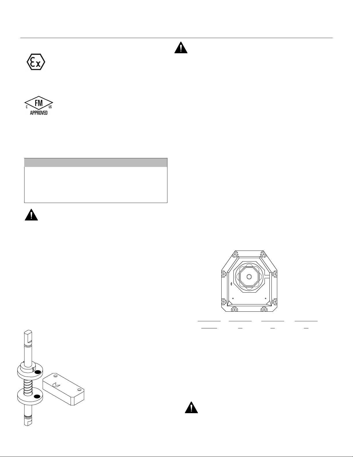
SETTING OF SWITCHES / SENSORS
1. Loosen the cover screws and remove the cover.
Move the valve or valve actuator assembly to the
closed position.
2. Determine which switch is to be set. Move the
corresponding cam as required until the switch
or sensor is actuated.
3. Move the valve or valve actuator assembly
to the open position and repeat step 2.
4. Replace the cover and tighten the screws.
CONDUIT CONNECTIONS A, B, C
B
MONITEUR
MONITEUR
OPEN
A
Conduit
Code
0
5
A
B
E
F
Conduit
Conduit
A
3/4” NPT
3/4” NPT
3/4” NPT
M20
M20
M25
M25
½”NPT Male and Female
Conduits are also available
C
B
n/a
n/a
M20
n/a
M25
WARNING: Unused conduit entries shall be
closed with suitable certified plugs to
maintain the enclosure type of protection
Conduit
C
3/4” NPT
3/4” NPT
M20
M20
M25
M25
M O N I T E U R D E V I C E S I N C O R P O R A T E D
3 6 C o m m e rce Road, Cedar Gro v e , N J 0 7 0 0 9 Te l . ( 9 7 3 ) 8 5 7 - 1 6 0 0 F a x ( 9 7 3 ) 8 5 7 - 7 2 8 9
Form IO-S3A-EN Rev. B Page 1
w w w . m o n i t e u r d e v i c e s . c o m
Installation and Operating Instructions
Moniteur
ELECTRICAL RATINGS
Code
1
3
4
2
T
Code
8
K
See www.moniteurdevices.com or contact Moniteur for electrical ratings on switch types not listed here.
Switch Type
Mechanical - SPDT
Gold Plated - SPDT
Mechanical - DPDT
Tungsten TTL - SPDT
Rhodium TTL - SPDT
Supply
Sensor
P & F NJ2-V3
P & F NBB3-V3-Z4
WARNING: I o prevent fire or explosion, use only
with a certified seal fitting within 18 inches of the position transmitter enclosure.
f indicated on the nameplate: t
Voltage
5-25 VDC
5-60 VDC
15A / 250VAC
1A / 120VAC
10A / 250VAC
3A / 120VAC
0.25A / 120VAC
Load Current /
Target Absent
< 1 mA
< 0.7 mA
DC RatingAC Rating
2.5A / 24VDC, 2A / 48 VDC,
0.5A / 125 VDC, 0.25A / 250 VDC
1A / 24VDC
7A / 24VDC
2A / 24VDC
1A / 24VDC
VPT Series - Sentinel S3
Load Current /
Target Present
3 - 15 mA
4 - 100 mA
Operation
NAMUR
PNP
WARNING: Flange Cover Bolts are Custom Captivating, contact Moniteur for
genuine replacements. M5 Flange Bolts of type 316SS with min yield of 91,000 psi
are an acceptable alternative.
WARNING: Potential Electrostatic Discharge Charging Hazard - Dissipate static
electricity on this device before handling.
Page 2
M O N I T E U R D E V I C E S I N C O R P O R A T E D
3 6 C o m m e rce Road, Cedar Gro v e , N J 0 7 0 0 9 Te l . ( 9 7 3 ) 8 5 7 - 1 6 0 0 F a x ( 9 7 3 ) 8 5 7 - 7 2 8 9
w w w . m o n i t e u r d e v i c e s . c o m
 Loading...