

Page 1

Installation and Operating Instructions
Moniteur
Series 40 Positioners
INSTALLATION & OPERATING INSTRUCTIONS
SERIES 40 Positioners
Form IO2-0406
Page 2

Installation and Operating Instructions
Moniteur
Description of Device
Moniteur's Series 40 pneumatic (3-15psi) and electropneumatic (4-20mA) positioners are advanced control
devices for rotary or linear valves which provide
unparalleled stability in difficult environments.
! Rugged Aluminum Housing With a Triple Corrosion-
Resistant Interior and Exterior Coating stands up to
harsh environments
! Reduced Bleed Pilot Valve reduces air consumption by
more than 50%
! Precise Calibration with simple SPAN and ZERO
adjustments.
! Magnetic 4-20 mA I/P Converter provides automatic
compensation for supply pressure, atmospheric
pressure and ambient temperature changes, and is
unaffected by EMF.
! Zero-Hysteresis Coupling System provides superior
accuracy and repeatability by eliminating "slop".
! Vibration Resistant Design maintains consistent
performance in poor conditions - no resonance effects
from 5 - 200Hz
! Stainless Steel Gauges
Series 40 Positioners
CAUTION: To reduce the risk of ignition of
hazardous atmospheres, disconnect the
device from the supply circuit before
opening. Keep assembly tightly closed
during operation.
Positioning
Moniteur Series 40 positioners can be mounted in any
position.
Mounting Brackets
For the installation of the rotary positioner, a mounting
bracket has been designed for actuators with the 80 x
30 mm NAMUR accessory pattern. For the 130 x 30
pattern, the block-type mounting bracket is available.
See diagrams below:
Bracket for the 80 x 30 NAMUR pattern
! Optional Limit Switches and 4-20mA Feedback
! Each Positoner Performance Tested - Test results are
included with each positioner
Bracket for the 130 x 30 NAMUR pattern
Part Number System
The series and part number are located on the nameplate. The part number can be deciphered in the table below.
4 N1
Series 40 Shaft Rating Pilot Feedback Gauges Indicator
Description
Series:
Pneumatic
Electro-Pneumatic
Shaft
Rotary NAMUR
Linear 10-80mm
Linear 80-150 mm
Code
40
41
N
L
S
-
E 1 S
Description
Electrical Ratings
Standard / None
Ex md IIT6
Intrinsically Safe
Pilot Valve
Standard Orifice
Small Orifice
Extra-Small Orifice
N
Code
S
E
I
1
2
3
-
F
Description
Position Feedback
None
4-20 mA
2 SPDT Limit Switches
Gauges
None
Standard
Indication
Flat Dial
Dome
Code
N
T
S
N
S
F
D
MONITEUR DEVICES INCORPORATED
36 Commerce Road, Cedar Grove, NJ 07009 Tel. (973) 857-1600 Fax (973) 857-7289
www.moniteurdevices.com
Page 1
Page 3
Installation and Operating Instructions
Moniteur
Specifications -3-15 psi Pneumatic
Input Signal 3 - 15 psig
Split Range Available
Impedance N/A
Stroke Range: 0 - 90°
Supply Range: 20 to 100 PSIG
Air Delivery: 7 SCFM
Air Consumption: 0.26 SCFM
Operating Temperature: -4° to +158° F
Linearity +/- 1%
Hysteresis 1% max.
Sensitivity +/- 0.5%
Repeatability +/- 0.5%
Pneumatic Connections: 1/8 NPT - Gauge Ports
1/4 NPT - Supply / Outlet
Series 40 Positioners
Specifications - 4-20 mA Electro-Pneumatic
Input Signal 4 - 20 mA @ 24 VDC
Split Range Available
Impedance 250 +/- 15 ohms
Stroke Range: 0 - 90°
Supply Range: 20 to 100 PSIG
Air Delivery: 7 SCFM
Air Consumption: 0.15 SCFM
Operating Temperature: -4° to +158° F
Linearity +/- 1%
Hysteresis 1% max.
Sensitivity +/- 0.5%
Repeatability +/- 0.5%
Pneumatic Connections: 1/8 NPT - Gauge Ports
1/4 NPT - Supply / Outlet
Enclosure: Designed to NEMA 4, 4X
Enclosure Weight: Approx. 4.8 lbs.
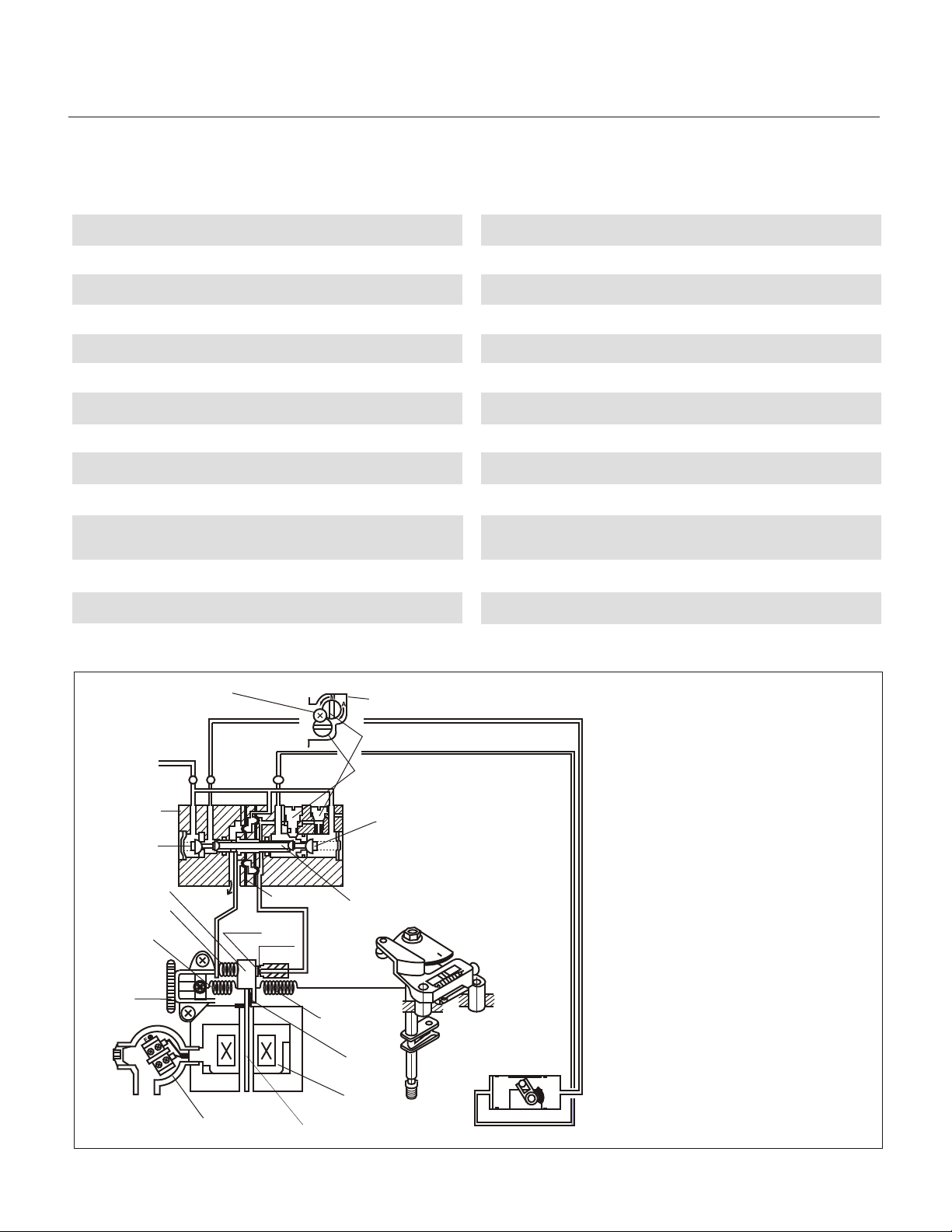
Principle Of Operation
Automatic
Manual
Change-over screw
(Built-in bleed restriction)
Sensitivity adjusting screw
(Adjusts GAIN)
Inlet Valve A
Exhaust Valve
Plate
Spring
Torque
Motor
Air Supply
Pilot Valve
Inlet Valve B
Counter Weight
Compensation
Spring
Zero
adjusting
Spring
Zero
adjusting
Screw
Stopper Screw
Do not move
Terminal Box
Flapper
Diaphragm
Nozzle
Feedback
Spring
Armature
Enclosure: Designed to NEMA 4, 4X
Enclosure Weight: Approx. 6.5 lbs.
OUT 1
As the signal current from the controller
increases, the plate spring of the torque
motor works as a pivot. As the armature
receives the rotary torque in the counter-
OUT 2
clockwise direction, the counter-weight
is pushed to the left, the clearance
between the nozzle and the flapper will
increase, and the nozzle back pressure
will decrease. As a result, the exhaust
valve of the pilot valve moves to the
right, and the output pressure of OUT1
increases (as OUT 2 decreases) to
move the actuator.
The movement of the actuator in turn
rotates the feedback shaft and spring.
The actuator stays in the position where
the spring force is balanced with the
force generated by the input current in
the torque motor. The compensation
spring is for direct feedback of the
Actuator
motion of the exhaust valve, and is
connected to the counter weight to
enhance the stability of the loop. The
zero point is adjusted by changing the
zero adjustment spring tension.
Page 2
MONITEUR DEVICES INCORPORATED
36 Commerce Road, Cedar Grove, NJ 07009 Tel. (973) 857-1600 Fax (973) 857-7289
www.moniteurdevices.com
Page 4
Installation and Operating Instructions
Moniteur
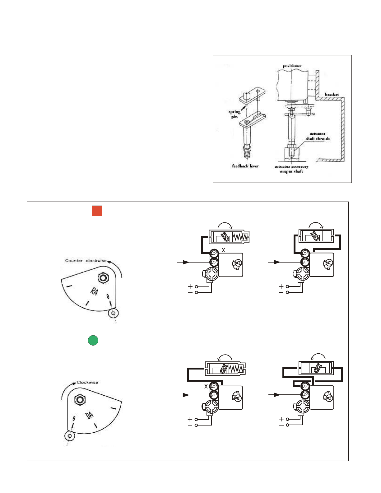
Mounting the Positioner and Attaching the
Feedback Lever
1. Mount the bracket to the actuator. The bracket kits include
screws for both metric and English threads.
2. Mount Feedback lever to actuator -three different feedback
levers are included in the bracket kit with different threads to
match your actuator and are labeled accordingly. Thread the
proper lever into the actuator first before mounting the positioner
and bracket to the actuator.
3. Once the bracket has been mounted to the actuator, mount the
positioner to the bracket. Be sure that the feedback lever is in
perfect alignment with the rotary actuator output shaft. The spring
pin of feedback shaft acts as a guide and should be placed in the
orifice of the feedback lever. Please note that linearity and
hysteresis will suffer if alignment is not correct.
Air Connections
Reverse Acting
6
Spring-Return Actuators Double-Acting Actuators
Series 40 Positioners
Actuator Stem Rotates Counter-Clockwise
As Input Signal Increases(Clockwise to
close) - Cam should be set with RA upwards
(standard factory setting)
Direct Acting
Actuator Stem Rotates Clockwise As Input
Signal Increases(Counter-clockwise to
close) - Cam should be set with DA upwards
6
OUT 1
OUT 2 Port must be plugged
Spring-Return Actuators Double-Acting Actuators
OUT 2
OUT 2
OUT 2OUT 1
OUT 1
OUT 1 Port must be plugged
MONITEUR DEVICES INCORPORATED
36 Commerce Road, Cedar Grove, NJ 07009 Tel. (973) 857-1600 Fax (973) 857-7289
www.moniteurdevices.com
Page 3
Page 5
Installation and Operating Instructions
Moniteur
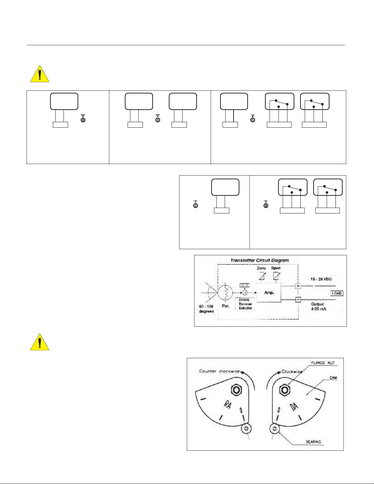
Wiring Diagrams
CAUTION: Always check that the electrical load is within the range stated on the nameplate. Failure
to remain within electrical ratings may result in damage to or premature failure of the electrical
switches, sensors or transmitter electronics.
4-20 mA
INPUT
+ --
1 2
INPUT
GROUND
4-20 mA
INPUT
+ --
1 2
INPUT
Series 41 Standard
4 - 20 mA input
4 - 20 mA input and output
Specifications - Current Output
Power Supply Rating 15 - 28 VDC loop power
Recommended
Power Supply 24 VDC
Output Signal 4 - 20 mA
Operating Temperature -20° to 175
Load Impedance 0 - 10K ohms at 24 VDC
Max. Output 55 mA DC
Linearity +/- 1.0%
Hysteresis 1.0% of full scale
Repeatability +/- 0.5% of full scale
Adjustment Zero and Span in Terminal Box
4-20 mA
OUTPUT
+ --
GROUND
Series 41 w / Output
° F
3 4
OUTPUT
4-20 mA
INPUT
+ --
1 2
INPUT
4-20 mA
OUTPUT
+ --
GROUND
w/ 4-20 mA output
1 2
INPUT
Series 40
Series 40 Positioners
NC
NO
GROUND
3 4 5
SWITCH 1
Series 41 w / Switches
4 - 20 mA input
GROUND
NC
1 2 3
SWITCH 1
w / Switch output
NC
C
6 7 8
SWITCH 2
C
NO
Series 40
NO
NC
C
NO
4 5 6
SWITCH 2
C
Specifications - Limit Switches
Contacts SPDT Form C
AC Rating 5A - 125 VAC / 3A - 250 VAC
DC Rating 1A - 24 VDC
Adjustment cams with set screws
Cam and Indicator Adjustment
WARNING: When adjusting or replacing cams, be sure to shut off air supply to the positioner.
Otherwise, the positioner might react suddenly and cause damage or injury.
1. Loosen the flange nut on the cam. Match the part of
the cam with "0" marked on it with the center of bearing,
as shown to the right. The span adjusting arm unit
should now be aligned.
2.Tighten the flange nut of cam after setting the cam.
3. After cam installation, proceed to adjust zero and
span. Once this is complete, secure the indicator with
the blot (M3) to the feedback shaft. The position for
indicator should be arranged according in the scale
(0 - 90 degrees) shown on the cover.
Page 4
MONITEUR DEVICES INCORPORATED
36 Commerce Road, Cedar Grove, NJ 07009 Tel. (973) 857-1600 Fax (973) 857-7289
www.moniteurdevices.com
Page 6
Installation and Operating Instructions
Moniteur
WARNING: Before adjusting the Span and Zero, or making any other adjustments to the positioner,
make sure all air connections are correct and match your actuator type. See page 3 for details.
Series 40 Positioners
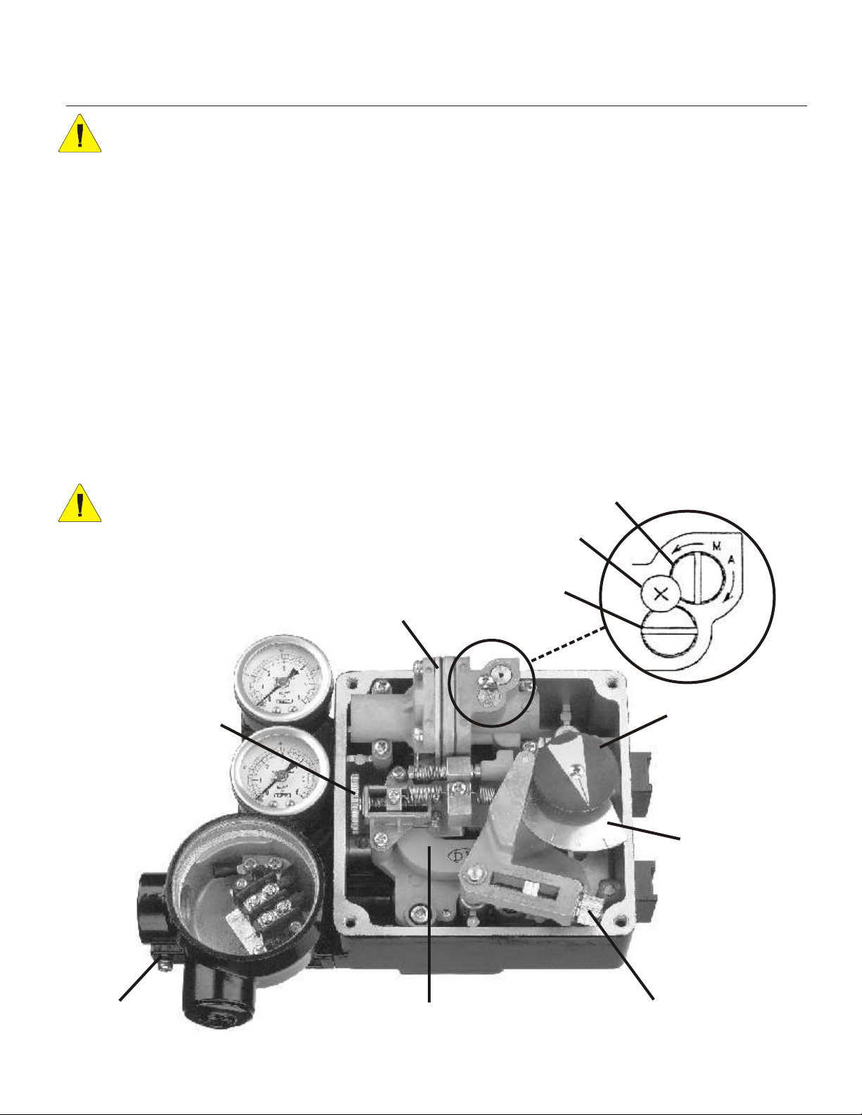
Span and Zero Adjustment
1) Set input signal to 4mA (24 VDC) while positioner is at the 0% or stroke starting point. Turn the zero
adjustment knob clockwise or counter clockwise to set the zero position.
2) Check the stroke of actuator by setting the signal to 20 mA at 24 VDC. If the stroke does not meet 100%, turn
the span adjustment screw clockwise or counter clockwise until 100% is reached.
3) Set input signal back to 4 mA (24 VDC) and adjust the zero adjustment screw until starting point is reached.
4) Repeat the process until the desired set points are reached.
NOTE: Due to variations in circuitry and environmental effects, often 0% is set at 4.5 mA and 100% 13.5 mA to
make sure that at the end points the valve will be fully open or fully closed.
Auto / Manual Operation - Pilot Valve Calibration
For manual operation using an external air regulator, set the Auto / Manual switch on the located on the pilot valve
to M. This will bypass the 4-20 mA input signal. Normally this function is not used.
The pilot valve is calibrated at the factory. For reliable operation of the positioner, no adjustments should be made.
WARNING: Adjusting the factory calibration screw
will void the warranty and may cause irreversible
damage to the positioner.
Auto / Manual Screw
Stopper Screw
Internal View Of the Series 40
Zero Adjusting Screw
Factory Calibration Screw
DO NOT MOVE
Pilot Valve
Visual Indicator
Cam
Terminal Box
MONITEUR DEVICES INCORPORATED
36 Commerce Road, Cedar Grove, NJ 07009 Tel. (973) 857-1600 Fax (973) 857-7289
Torque Motor I/P
www.moniteurdevices.com
Span Adjusting Screw
Page 5
Page 7
Installation and Operating Instructions
Moniteur
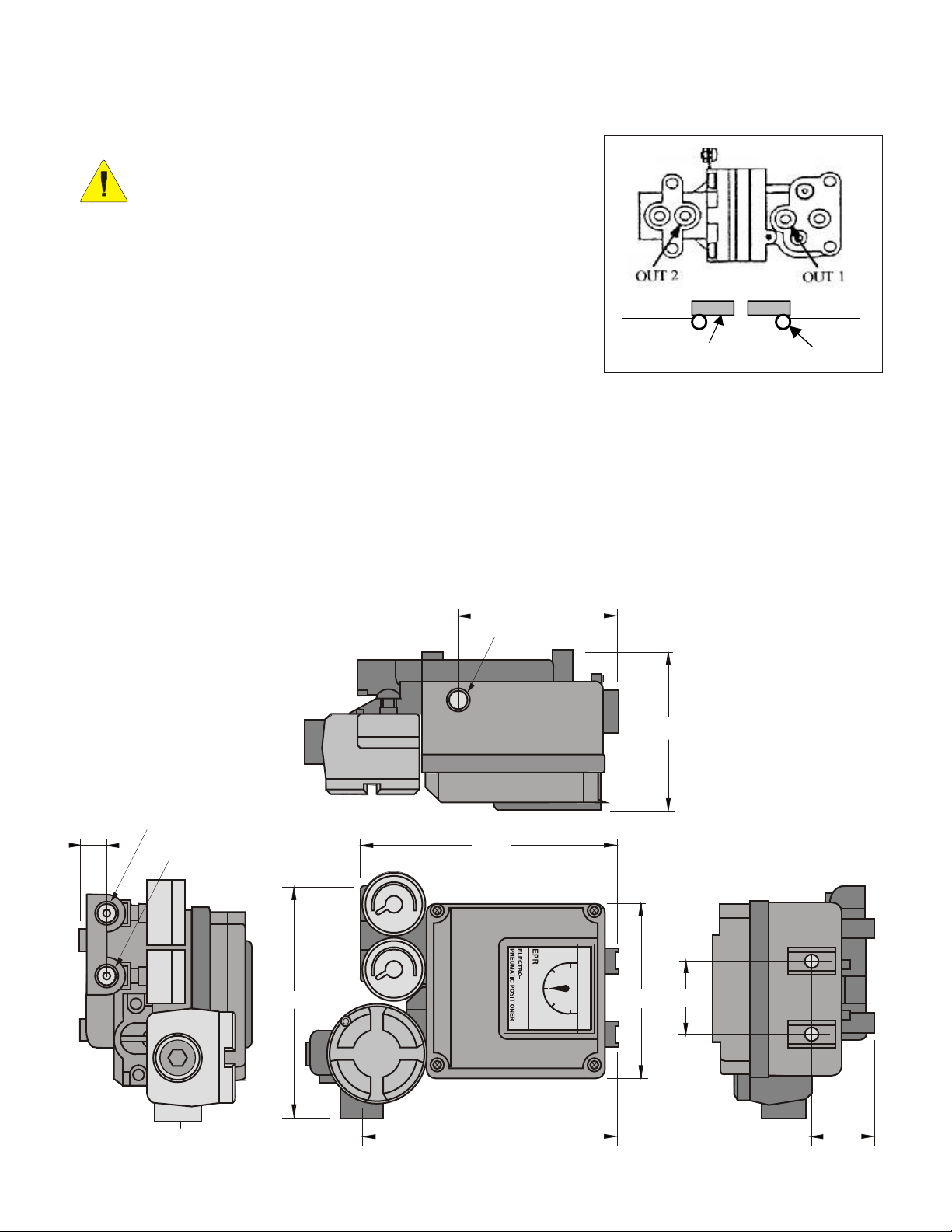
Optional Restricted Pilot Valve Orifice
WARNING: Before removing pilot valve, be sure to disconnect
positioner from the signal and compressed air source.
For improved control using smaller actuators, a restricted pilot valve orifice
kit is included with the positioner. To install, the pilot valve must be
removed from the positioner. Remove the four screws holding the pilot to
the positioner body. As you remove the valve, be sure to hold the
compensation spring (see page 2) in place. Flip the valve so the bottom
faces you. Remove the o-rings from the out 1 and out 2 ports (as shown in
the diagram at right). Place the orifice plates in their place with new o-rings
above them, and re-install the pilot valve, making sure the compensation
spring is back in place. The positioner is now set up for smaller actuators.
Troubleshooting Tips
Hunting
* If your actuator is small, install orifice resitrictions
in ports 1 and 2 of the pilot valve.
* The nozzle might be clogged. Take the metal wire
located in the positioner cover and clean the
nozzle.
Poor Linearity
* Air supply might be unstable - check or install a
pressure regulator.
* Check Zero and Span adjustments
* Loose feedback lever - tighten feedback lever
Poor Hysteresis
* Loose mounting of the actuator to the positioner -
tighten the mounting bracket.
* Adjust the seat, using the seat adjuster (double
acting actuators only)
Series 40 Positioners
orifice
o-ring
Dimensions (in.)
.67
OUT 1 (1/4" NPT)
SUPPLY (1/4" NPT)
6.30
4.33
OUT 2 (1/4" NPT)
6.61
4.38
Moniteur
1.97
4.80
Page 6
6.61
1.63
MONITEUR DEVICES INCORPORATED
36 Commerce Road, Cedar Grove, NJ 07009 Tel. (973) 857-1600 Fax (973) 857-7289
www.moniteurdevices.com
Page 8
Moniteur
Moniteur Devices Inc
36 Commerce Road
Cedar Grove, NJ 07009 USA
Tel. (973) 857-1600
Fax (973) 857-7289
E-mail [email protected]
www.moniteurdevices.com
 Loading...