

Moniteur IO3-0405 User Manual
DESCRIPTION OF DEVICE
The Moniteur Valve Position Transmitter is an electromechnical device that produces an analog output signal
representative of the angular displacement of a quarter
turn valve, or other device operating between 0 and 90
degrees.
FACTORY SETTINGS
Clockwise - to - Close operation (see fig A)
Resistive: 0 - 1k Ohms (selectable)
Current: 4mA Closed , 20mA Open
INSTALLATION
Install the Valve Position Transmitter to the
valve/actuator package. Remove the enclosure cover
and wire unit to the appropriate terminal points.
Provided power must be within the operating
specifications of the devices.
Calibration Procedure (Resistive Output Models)
Calibration Instructions for Moniteur
Transmitter Series - Form IO3-0405
CAUTION: To reduce the risk of ignition of
hazardous atmospheres, disconnect the
device from the supply circuit before
opening. Keep assembly tightly closed
during operation.
CAUTION: Keep fingers and all objects away
from moving gears. Never cycle or move
the valve while adjusting the transmitter.
Verify the position of the valve/actuator package to ensure that the valve is in the position where the resistive
1.
reading will be '0' ohms. (Normally the valve closed position)
For clockwise to close operation(see fig. A) use an ohmmeter to measure resistance between terminal points 9
2.
and 10 on the terminal strip . For counter-clockwise rotation to close, measure resistance between terminal
points 10 and 11 on the terminal strip. In this position, the meter should read "0 ohms" or slightly higher.
If the resistive output does not read near "0 ohms" then a macro adjustment must be made. This is adjusted by
3.
by disengaging the main drive gear. Lift the large center gear slightly from the main transmitter shaft and
rotating the main gear until the desired reading is achieved. Release the main drive gear so that it re-engages
with the main drive shaft.
Cycle the valve/actuator package to the full open position. Reading at 90 degrees of rotation should be close to
4.
1000 ohms +/- 20% . (Less for smaller rotations, more for larger)
Cycle the valve, re-check the output. Re-calibrate if necessary.
5.
Close the transmitter housing. Tighten all screws.
6.
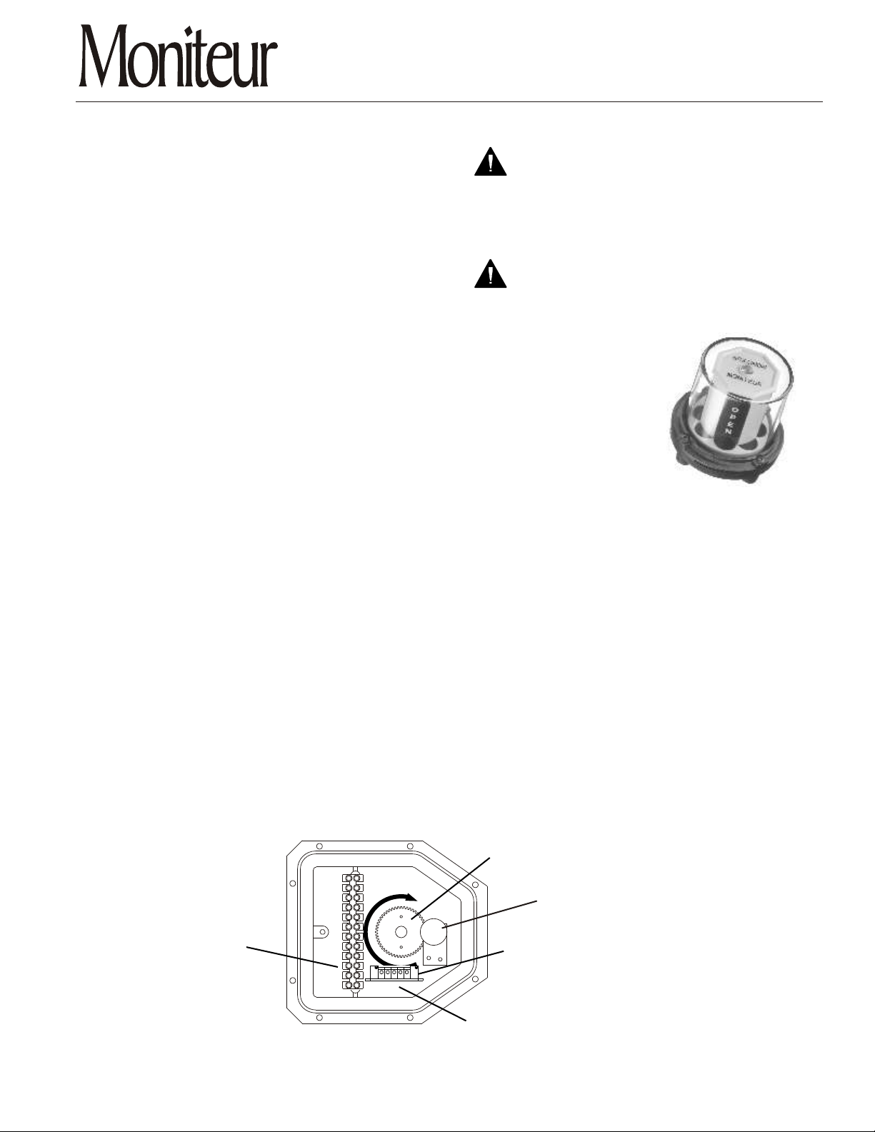
Terminal Block
Figure A
c
o
l
C
C
O
L
C
SPAN
Main Drive Gear
k
W
-
i
s
e
ZERO
--+BWR
Potentiometer
4-20 mA Transmitter
(current unit only)
Circuit Terminal Block
MONITEUR DEVICES INCORPORATED
36 Commerce Road, Cedar Grove, NJ 07009 Tel. (973) 857-1600 Fax (973) 857-7289
www.moniteurdevices.com
Form IO3-0405
Calibration Instructions for Moniteur
Transmitter Series - Form IO3-0405
Calibration Procedure (Resistive Output Models)
Instructions for clock-wise to close operation. See
reverse instructions for counter-clock wise to close.
Verify the position of the valve/actuator package to ensure that the valve is in the 4mA reading position
1.
(normally the valve closed position).
Connect positive and negative leads to the appropriate terminal points. Insure that voltage values are within
2.
units rated values.
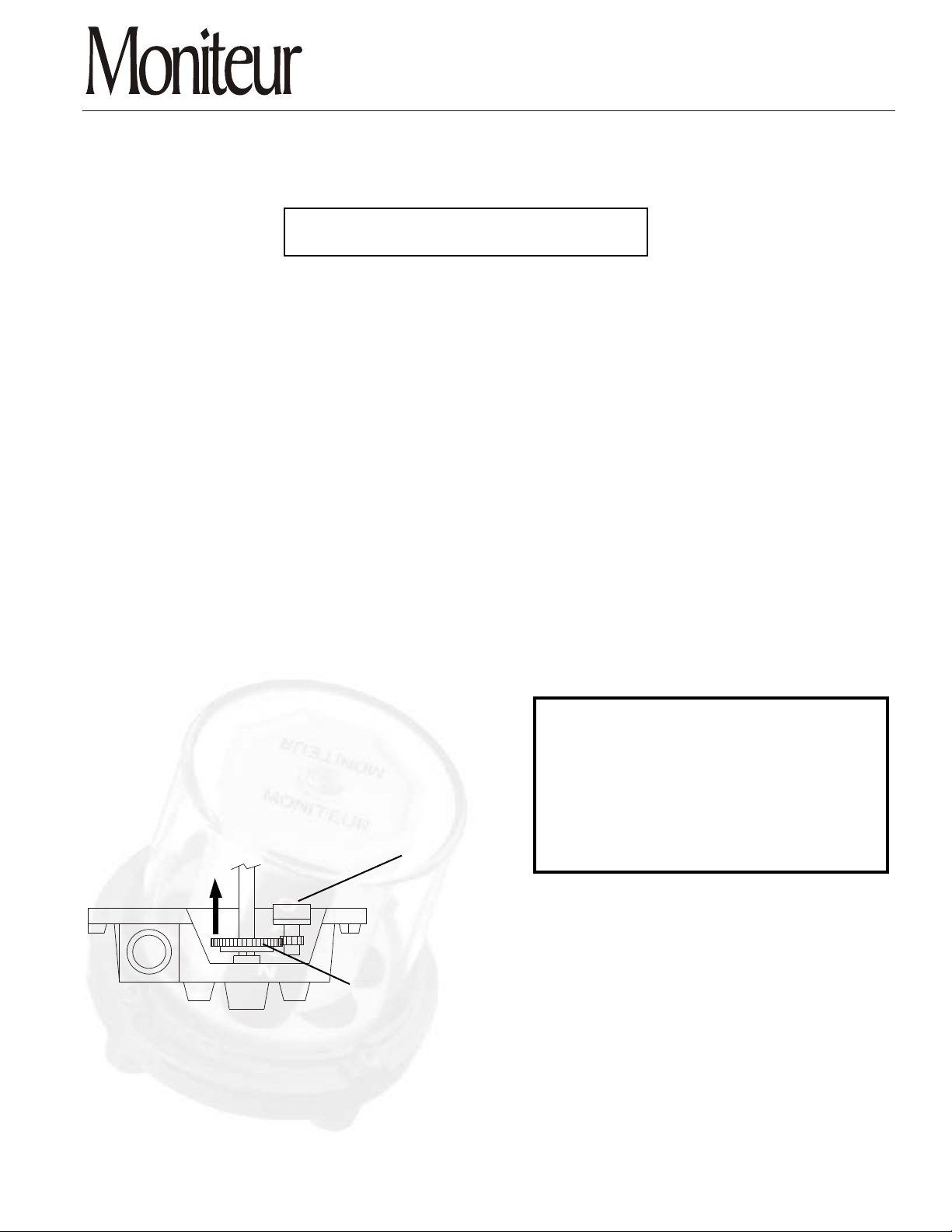
Connect a milliamp meter to the circuit. Lift the large center gear slightly from the main transmitter shaft and
3.
begin to rotate clockwise. Watch the amp meter while rotating. Reading will slowly decrease until the
potentiometer's limit has been reached. At this point, the milliamp output will jump or zero out. Stop rotation
of the main gear. Rotate the main gear counter-clock-wise approximately 1 tooth (10degrees).
Release the main drive gear so that it re-engages with the main drive shaft.
4.
With a small screw driver, turn the adjustment screw on the transmitter board adjustment pot("zero") until the
5.
meter reads 4mA (See Fig A).
Cycle the valve 90 degrees to the full open position.
6.
Turn the adjustment screw on the transmitter board adjustment pot ("span") (See Fig. A)
7.
until the meter reads 20mA.
Cycle the valve and recheck outputs at both ends of stroke. Make readjustments as necessary.
8.
Close the transmitter housing. Tighten all screws.
9.
Reverse Instructions
To use the transmitter with valve systems that rotate in the
counter-clock-wise direct to close, remove all power from the
system. On the circuit board terminal block, the BLACK and
WHITE wire leads must be switched. Connect the BLACK lead
to the terminal point marked (W) and the WHITE lead
connected to the terminal point marked (B). Tighten terminal
block screws. Lastly, when following directions listed above,
reverse the rotation (words in bold print) of the directions. (i.e.
Potentiometer
clockwise becomes counter-clock-wise). Follow directions
above.
Main Drive Gear
Figure B
MONITEUR DEVICES INCORPORATED
36 Commerce Road, Cedar Grove, NJ 07009 Tel. (973) 857-1600 Fax (973) 857-7289
www.moniteurdevices.com
 Loading...