

Moniteur Indicateur VPT User Manual
Installation and Operating Instructions
VPT Series - Form IO1-0202
DESCRIPTION OF DEVICE
The Moniteur Visual Indicator is a mechanical device that
graphically displays the angular displacement of a quarter
turn valve or any other device operating between 0 and 90
degrees. The Moniteur Indicator represents a true
indication of valve position. It is infinitely adjustable, and
delivers a 100% change of indication, displaying 90
degrees of rotation by utilizing an amplified mechanical
drive. Moniteur Valve Position Transmitters have
enclosures meeting the following requirements:
Sentinel
- Nema 4, 4x - Watertight, Nema 7
Explosion-proof and Nema 9 Dust - Ignition-proof,
Class 1, Division 1 Groups C&D, Class I, Division 1
Groups E, F, & G, Class 1, Division 2 Groups A, B
(TTL switches and Inductive Sensors only)
Sentinel II -
Nema 4, 4x Watertight, Nema 7
Explosion-proof and Nema 9 Dust - Ignition-proof,
Class 1, Division 1 Groups A, B, C&D, Class II,
Division 1, Groups E, F, & G
Watchman / Watchman II / Survivor / Scout
- Nema 4,
4x -Watertight
Survivor II
- Nema 4, 4x - Watertight,
Series ‘Q’(FM) Install per drawing no. S2CF
Non-incendive Division 2 All Groups
Series ‘R’(CSA)
Division 2 All Groups
The Survivor II unit must be supplied by an SELV
source in accordance with C22.2 No. 1010.1 Annex H.
PART NUMBER SYSTEM
The series and part number are located
on the nameplate. The part number can
be deciphered in the table below.
Description
Series
Sentinel
Sentinel-II
Watchman
Watchman-II
Survivor
Survivor-II (FM)
Survivor-II (CSA)
Scout
Indicateur
Cover
With Moniteur
Flat Cover (No Moniteur)
Moniteur
No Indicator
Black / Yellow
3-Way Path O,T,F
4-Way Path S
180 degree “T”
Green, Red, Blue / White
Green / Red
Red / Green
0-100%
Code
A
C
F
H
P
Q
R
V
I
M
F
N
Y
O,T,F
S
1
G,R,B
A
C
P
A
Series Cover Moniteur Bearing Shaft Switch Quantity Conduit
Description
Bearing
Bronze
303 Stainless Steel
Shaft
Standard 303 SS
Standard 316 SS
NAMUR 303 SS
Long NAMUR 303 SS
Switch Type
Cherry 15A
SPDT Mechanical
Tungsten TTL 3A
SPDT Non-Contact
Prism Gold Plated 1A
SPDT Mechanical
ITW 10A
DPDT Mechanical
Rhodium TTL 1A
SPST Non-Contact
Krystal TTL 0.3A
SPDT Non-Contact
NEO-X 0.3A
NO Sensor
M Y B 5 1 2 0
M O N I T E U R D E V I C E S I N C O R P O R A T E D
36 Commerce Road, Cedar Grove, NJ 0 7009 Tel. (973) 857-1600 Fax (973) 857-7289
Form IO1-0202
w w w . m o n i t e u r d e v i c e s . c o m
CAUTION: To reduce the risk of ignition of
hazardous atmospheres, disconnect the
device from the supply circuit before
opening. Keep assembly tightly closed
during operation.
Pollution Degree - "4"
Installation Category - "I”
Operating Temperature (deg. C) -40 to 80
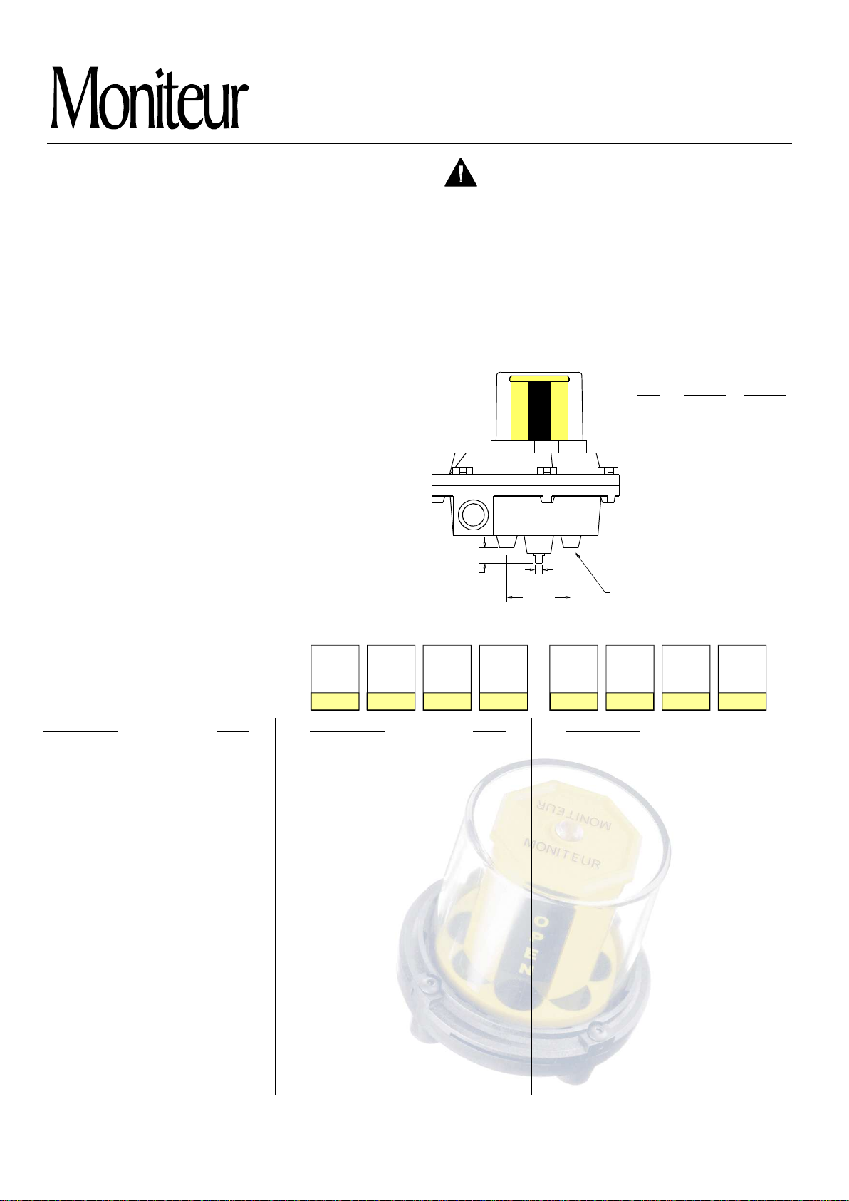
Positioning-
Moniteur Valve Position Transmitters can
be mounted in any position.
Mounting Dimensions (for all switches)
O
P
E
N
STD NAMUR NAMUR
AB0.249 0.156 0.156
0.53 0.62 1.25
B
SQ. BOLT PATTERN
A
2.25
5/16-18 (4x)
-
Code
B
S
1
3
5
E
1
2
3
4
7
L
A
Description
Rhodium TTL 1A
SPDT Non-Contact
Bifurcated TTL 3A
SPST Non-Contact
P&F NJ2-V3 NAMUR
Inductive Sensor
P&F NBB3-V3-Z4
Inductive Sensor
Switch Quantity
Conduit (Watchman / Survivor)
(2) ½" F NPT
(3) ½" F NPT
(1) ½" F + (1) ½" M NPT
Conduit (Sentinel)
(2) ¾" F NPT
(3) ¾ F
"
(2) ¾" F + (1) ½" F NPT
(1) ¾ F + (1) ½ M NPT
" "
Output
(add suffix to part number)
Current 4 - 20mA
Resistive 0 - 1k
Ω
LONG
Code
T
B
8
K
1-6
0
6
8
0
5
6
8
- 420
- 1K
Page 1
Moniteur Devices Inc
Installation and Operating Instructions
INSTALLATION - ADJUSTING THE VISUAL INDICATOR
VPT Series
1. Mount the valve position transmitter to the valve or actuator with the
correct mounting bracket.
2. Determine the true valve position and compare the Moniteur's
Indication with the true valve position. If the Moniteur display is
synchronized, proceed to Step 12. If it is not, continue to Step 3.
3.
Remove the clear Moniteur cover by turning it counter-clockwise to
disengage the detent and then lift it off.
Determine the level of
adjustment that needs to be made. If only a small adjustment is
necessary (less than 20 degrees in either direction), proceed to step 4.
If a larger adjustment is required, such as 45, 90 or 135 degrees from
default, proceed to step 7.
4.
Remove the Moniteur Visual Indicator by lifting it upward off the shaft
and the Infinite Adjusting Ring.
Loosen screws B and C shown in fig.1
(do not remove screws). The Infinite adjusting ring should rotate freely
over the enclosure cover of the Valve Position Transmitter.
5. Return the Moniteur Indicator to the output shaft. As it slides down
along the shaft, be sure that the Moniteur Indicator's base engages
the Infinite Adjusting Ring on pins “E”. (fig.1)
6. Rotate the Moniteur Indicator by applying a light rotational force to the
vertical vanes to synchronize it with the true valve position. Once
aligned, proceed to Step 9. If further adjustment is necessary, you will
need to continue with Step 7.
7.
Remove the Moniteur Visual Indicator by lifting it upward off the shaft
and the Infinite Adjusting Ring. Remove screws B and C from the
InfiniteAdjusting Ring.
Rotate the setting ring and match the number on
the plastic ring with the number cast into the enclosure, according to
the following requirements:
90 - 90
45 - 45
135 - 135
180 - 180
: as shipped from the factory - shipped as “Open”.
: “Open”is 45 degrees CCW in travel from default.
: Open”is 45 degrees CW in travel from default.
“
: “Open”is 90 degrees CW or CCW from default.
(This is the setting to switch default indication from
Open to Closed.)
Return screws B and C to their appropriate threaded holes,
but do not tighten them completely.
Now return the Moniteur
Indicator to the output shaft. Be sure that the Indicator's
base engages the infinite adjusting ring on pins “E”. (fig.1)
8. Rotate the Moniteur Indicator by applying a light rotational
force to the vertical vanes to further synchronize the
Indicator with the true valve position.
9. Remove the Moniteur Indicator, being careful not to rotate
the Infinite Adjustment Ring.
Hold Ring stationary and
tighten screws B and C.
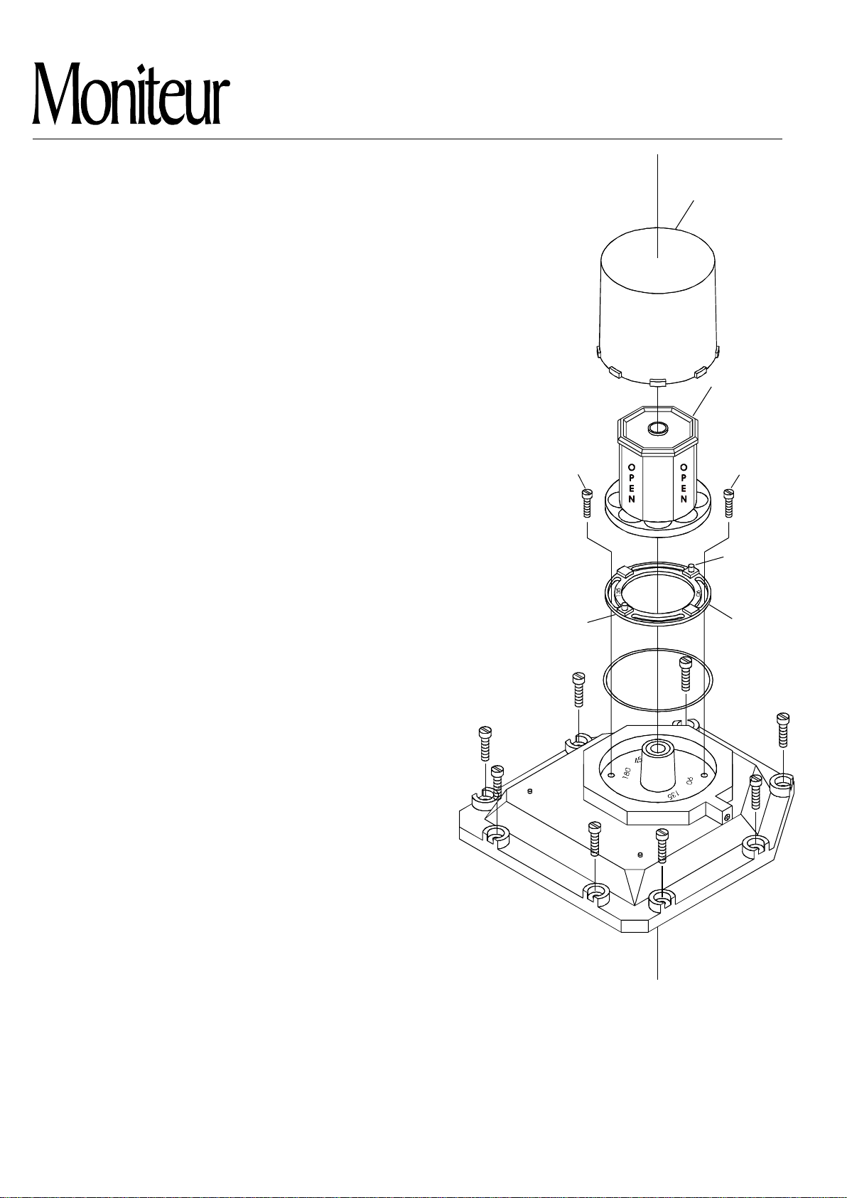
Pin “E”
Clear Cover
Moniteur
MONITEUR
MONITEUR
Screw “C”Screw “B”
Pin “E”
45
180
Adjusting
Ring “A”
10. Return the Moniteur Indicator being certain that both the output shaft and pins “E”
of the Infinite Adjusting Ring are engaged.
11. Return the clear Moniteur cover by inserting it into the breach lock on the
enclosure cover and turning it Clock-wise until the unit engages the detent.
12. Cycle the valve to the opposite extremity. If the Moniteur Indicator is displaying the
correct valve position, installation is complete. If not, it is probably because the
actuator is not moving exactly 90 degrees. Adjust the stroke of the actuator so that
it is rotating 90 degrees and the Moniteur Indicator will indicate the correct valve
position. Installation is now complete.
M O N I T E U R D E V I C E S I N C O R P O R A T E D
Page 2
36 C ommerce Road, Ceda r Grove, NJ 07009 Tel. (973) 857-1600 Fax (973) 857-7289
w w w . m o n i t e u r d e v i c e s . c o m
Moniteur Devices Inc
Fig. 1
 Loading...