

Moniteur 667 User Manual
Companion VPT
Moniteur
Parts Listing
Parts Listing
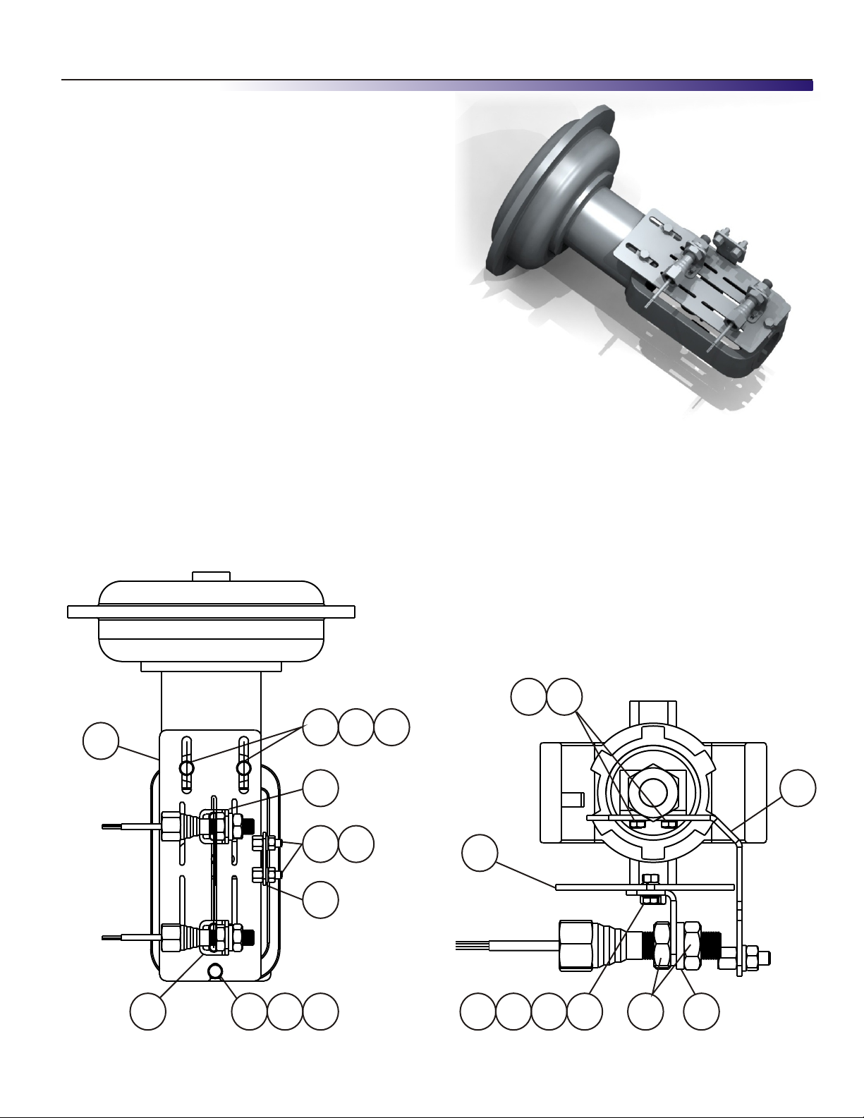
Item Qty Description
Item Qty Description
1 1 Switch-Actuator Target Bracket
1 1 Switch-Actuator Target Bracket
2 1 Main Mounting Bracket
2 1 Main Mounting Bracket
3 2 Switch Mounting Bracket
3 2 Switch Mounting Bracket
4 3 5/16-18 x 3/4” Hex Head Cap Screw
4 3 5/16-18 x 3/4” Hex Head Cap Screw
5 5 5/16” Split Lock Washer
5 5 5/16” Split Lock Washer
6 5 5/16” Flat Washer (0.75” OD)
6 5 5/16” Flat Washer (0.75” OD)
7 4 M5 Hex Head Screw
7 4 M5 Hex Head Screw
8 4 M5 Hex Nut
8 4 M5 Hex Nut
9 4 M5 Lock Washer
9 4 M5 Lock Washer
10 8 M5 Flat Washer
10 8 M5 Flat Washer
11 2 5/8” Split Lock Washer
11 2 5/8” Split Lock Washer
12 4 5/8-18 Jam Nut (supplied w/Companion)
12 4 5/8-18 Jam Nut (supplied w/Companion)
13 2 5/16-18 Hex Nut (supplied w/Companion)
13 2 5/16-18 Hex Nut (supplied w/Companion)
14 2 5/16” Split Lock Washer (supplied w/Companon)
14 2 5/16” Split Lock Washer (supplied w/Companon)
Mounting Instructions
1. Attach the switch-actuator target bracket (item 1)
to the stem connector with the existing screws,
and add the flat washers and lock washers (items
5 and 6).
2. Mount main bracket (item 2) to the actuator with
items 4, 5 and 6
3. Mount switch mounting brackets (item 3) to main
mounting bracket (item 1) with items 7,8,9 and 10.
Mounting Instructions - Fisher 657 / 667 Bracket Kits
4. Thread a Companion VPT through each switch
mounting bracket (item 3) and secure with 2 jam
nuts (item 12 - supplied with the Companion) and
lock washer (item 11).
5. Mount the two magnetic triggers (supplied with the
Companion) to the switch-actuator arm (item 1) with
items 13 and 14 (supplied with the Companion).
6. Adjust the Companion switches on the main
mounting bracket (item 2) and the magnetic triggers
on the switch-actuator bracket (item 1) to the
appropriate positions for the switches to sense each
end of travel of the actuator.
65
2
4
M O N I T E U R D E V I C E S I N C O R P O R A T E D
3 6 C o m m e rce Road, Cedar Gro v e , N J 0 7 0 0 9 Te l . ( 9 7 3 ) 8 5 7 - 1 6 0 0 F a x ( 9 7 3 ) 8 5 7 - 7 2 8 9
4 5 6
3
13 14
1
5 63
w w w . m o n i t e u r d e v i c e s . c o m
2
8 97 10
12
1
11
Form IO-LCS-0909
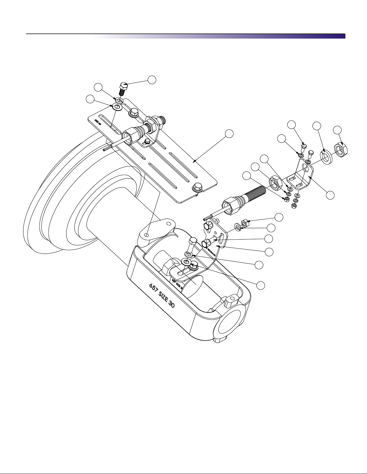
Companion VPT
Moniteur
Exploded View
66
Mounting Instructions - Fisher 657 / 667 Bracket Kits
44
55
77
11
1010
1010
99
88
1111
1212
33
Parts Listing
Item Qty Description
1 1 Switch-Actuator Target Bracket
2 1 Main Mounting Bracket
3 2 Switch Mounting Bracket
4 3 5/16-18 x 3/4” Hex Head Cap Screw
5 5 5/16” Split Lock Washer
6 5 5/16” Flat Washer (0.75” OD)
7 4 M5 Hex Head Screw
8 4 M5 Hex Nut
9 4 M5 Lock Washer
10 8 M5 Flat Washer
11 2 5/8” Split Lock Washer
12 4 5/8-18 Jam Nut (supplied w/Companion)
13 2 5/16-18 Hex Nut (supplied w/Companion)
14 2 5/16” Split Lock Washer (supplied w/Companon)
1313
1414
44
22
55
66
M O N I T E U R D E V I C E S I N C O R P O R A T E D
3 6 C o m m e rce Road, Cedar Gro v e , N J 0 7 0 0 9 Te l . ( 9 7 3 ) 8 5 7 - 1 6 0 0 F a x ( 9 7 3 ) 8 5 7 - 7 2 8 9
w w w . m o n i t e u r d e v i c e s . c o m
Form IO-LCS-0909
 Loading...