

Moniteur 50 User Manual
SIPART PS2 6DR400x-xx
SIPART PS2 PA 6DR410x-xx
Electropneumatic Positioner for
Linear and Rotary Actuators
Manual Order No. C79000-G7476-C158-1

SIPART, SITRANS, SIMATIC
are Siemens registered trademarks.
All other product or system names are (registered) trademarks of their respective owners and must be treated
accordingly .
The reproduction, transmission or use of this document or its contents is not permitted without express written authority . Offenders will be liable
for damages.
All rights created by the granting of patents or registration of a design are reserved.
Technical data subject to change without notice.
2

Contents
0 Information for the Operator 0-1. . . . . . . . . . . . . . . . . . . . . . . . . . . . . . . . . . . . . . . . . . . . .
0.1 General information 0-1. . . . . . . . . . . . . . . . . . . . . . . . . . . . . . . . . . . . . . . . . . .
0.2 Warning notes 0-2. . . . . . . . . . . . . . . . . . . . . . . . . . . . . . . . . . . . . . . . . . . . . . . .
0.3 Qualified personnel 0-3. . . . . . . . . . . . . . . . . . . . . . . . . . . . . . . . . . . . . . . . . . . .
0.4 Use as intended 0-4. . . . . . . . . . . . . . . . . . . . . . . . . . . . . . . . . . . . . . . . . . . . . .
0.5 Technical documentation 0-4. . . . . . . . . . . . . . . . . . . . . . . . . . . . . . . . . . . . . . .
0.6 Warranty information 0-4. . . . . . . . . . . . . . . . . . . . . . . . . . . . . . . . . . . . . . . . . .
0.7 Information about delivery 0-5. . . . . . . . . . . . . . . . . . . . . . . . . . . . . . . . . . . . . .
0.8 Standards and regulations 0-5. . . . . . . . . . . . . . . . . . . . . . . . . . . . . . . . . . . . . .
1 Introduction 1-1. . . . . . . . . . . . . . . . . . . . . . . . . . . . . . . . . . . . . . . . . . . . . . . . . . . . . . . . . . . . .
1.1 General information about the device 1-1. . . . . . . . . . . . . . . . . . . . . . . . . . . .
1.2 The PROFIBUS 1-2. . . . . . . . . . . . . . . . . . . . . . . . . . . . . . . . . . . . . . . . . . . . . . .
1.2.1 PROFIBUS DP and PROFIBUS PA 1-3. . . . . . . . . . . . . . . . . . . . . . . . . . . . . .
1.2.2 Properties of the PROFIBUS PA 1-4. . . . . . . . . . . . . . . . . . . . . . . . . . . . . . . .
2 Design and Method of Operation 2-1. . . . . . . . . . . . . . . . . . . . . . . . . . . . . . . . . . . . . . . . .
2.1 Overview 2-1. . . . . . . . . . . . . . . . . . . . . . . . . . . . . . . . . . . . . . . . . . . . . . . . . . . . .
2.2 Components 2-2. . . . . . . . . . . . . . . . . . . . . . . . . . . . . . . . . . . . . . . . . . . . . . . . . .
2.2.1 Motherboard 2-3. . . . . . . . . . . . . . . . . . . . . . . . . . . . . . . . . . . . . . . . . . . . . . . . . .
2.2.2 Electrical connections 2-3. . . . . . . . . . . . . . . . . . . . . . . . . . . . . . . . . . . . . . . . . .
2.2.3 Pneumatic connections 2-4. . . . . . . . . . . . . . . . . . . . . . . . . . . . . . . . . . . . . . . .
2.2.4 Mounting kit 2-6. . . . . . . . . . . . . . . . . . . . . . . . . . . . . . . . . . . . . . . . . . . . . . . . . .
2.2.5 Purging air switchover 2-6. . . . . . . . . . . . . . . . . . . . . . . . . . . . . . . . . . . . . . . . .
2.2.6 Restrictors 2-6. . . . . . . . . . . . . . . . . . . . . . . . . . . . . . . . . . . . . . . . . . . . . . . . . . .
2.3 Method of operation 2-7. . . . . . . . . . . . . . . . . . . . . . . . . . . . . . . . . . . . . . . . . . .
2.4 State as supplied 2-12. . . . . . . . . . . . . . . . . . . . . . . . . . . . . . . . . . . . . . . . . . . . . .
2.5 Optional modules 2-12. . . . . . . . . . . . . . . . . . . . . . . . . . . . . . . . . . . . . . . . . . . . .
2.5.1 HART module (devices without PROFIBUS PA only) 2-16. . . . . . . . . . . . . . .
2.5.2 Alarm module 2-18. . . . . . . . . . . . . . . . . . . . . . . . . . . . . . . . . . . . . . . . . . . . . . . . .
2.5.3 Jy module 2-18. . . . . . . . . . . . . . . . . . . . . . . . . . . . . . . . . . . . . . . . . . . . . . . . . . . .
2.5.4 Accessories 2-19. . . . . . . . . . . . . . . . . . . . . . . . . . . . . . . . . . . . . . . . . . . . . . . . . .
AG 1198 MG 124 en
Positioner SIP ART PS2/SIPART PS2 PA
C79000-G7476-C158–01
i

3 Preparing for Operation 3-1. . . . . . . . . . . . . . . . . . . . . . . . . . . . . . . . . . . . . . . . . . . . . . . . . .
3.1 Instrument identification (type code) 3-1. . . . . . . . . . . . . . . . . . . . . . . . . . . . .
3.2 Dimension drawings 3-2. . . . . . . . . . . . . . . . . . . . . . . . . . . . . . . . . . . . . . . . . . .
3.3 Assembly 3-3. . . . . . . . . . . . . . . . . . . . . . . . . . . . . . . . . . . . . . . . . . . . . . . . . . . .
3.3.1 Mounting kit “Linear Actuator” 6DR4004–8V 3-4. . . . . . . . . . . . . . . . . . . . . .
3.3.2 Assembly Sequence (see Fig. 3-5) 3-4. . . . . . . . . . . . . . . . . . . . . . . . . . . . . .
3.3.3 Mounting kit “Rotary Actuator” 6DR4004–8D 3-7. . . . . . . . . . . . . . . . . . . . . .
3.3.4 Assembly Sequence (see Fig. 3-6) 3-7. . . . . . . . . . . . . . . . . . . . . . . . . . . . . .
3.4 Electrical connection 3-10. . . . . . . . . . . . . . . . . . . . . . . . . . . . . . . . . . . . . . . . . . .
3.4.1 Connections variations not ex-proof (devices without
PROFIBUS P A) 3-10. . . . . . . . . . . . . . . . . . . . . . . . . . . . . . . . . . . . . . . . . . . . . . .
3.4.2 Connection variants not protected from explosion hazard (devices with PRO-
FIBUS P A) 3-13. . . . . . . . . . . . . . . . . . . . . . . . . . . . . . . . . . . . . . . . . . . . . . . . . . .
3.4.3 Connection variations options not ex-proof 3-15. . . . . . . . . . . . . . . . . . . . . . .
3.4.4 Connection variations ex-proof 3-17. . . . . . . . . . . . . . . . . . . . . . . . . . . . . . . . . .
3.4.5 Connection variations ex-proof (devices with PROFIBUS PA) 3-18. . . . . . .
3.4.6 Connection variations options ex-proof (devices with
PROFIBUS P A) 3-18. . . . . . . . . . . . . . . . . . . . . . . . . . . . . . . . . . . . . . . . . . . . . . .
3.5 Pneumatic connection 3-20. . . . . . . . . . . . . . . . . . . . . . . . . . . . . . . . . . . . . . . . .
3.6 Commissioning 3-21. . . . . . . . . . . . . . . . . . . . . . . . . . . . . . . . . . . . . . . . . . . . . . .
4 Operation 4-1. . . . . . . . . . . . . . . . . . . . . . . . . . . . . . . . . . . . . . . . . . . . . . . . . . . . . . . . . . . . . . .
4.1 Display 4-1. . . . . . . . . . . . . . . . . . . . . . . . . . . . . . . . . . . . . . . . . . . . . . . . . . . . . .
4.2 Control pushbuttons 4-1. . . . . . . . . . . . . . . . . . . . . . . . . . . . . . . . . . . . . . . . . . .
4.3 Modes 4-2. . . . . . . . . . . . . . . . . . . . . . . . . . . . . . . . . . . . . . . . . . . . . . . . . . . . . . .
4.4 Parameters 4-3. . . . . . . . . . . . . . . . . . . . . . . . . . . . . . . . . . . . . . . . . . . . . . . . . . .
4.5 Operation via PROFIBUS P A 4-22. . . . . . . . . . . . . . . . . . . . . . . . . . . . . . . . . . .
4.5.1 Useful data via PROFIBUS 4-24. . . . . . . . . . . . . . . . . . . . . . . . . . . . . . . . . . . . .
4.5.2 Diagnostics acc. to PROFIBUS DP (DDLM_Slave_Diag) 4-31. . . . . . . . . . .
5 Service and Maintenance 5-1. . . . . . . . . . . . . . . . . . . . . . . . . . . . . . . . . . . . . . . . . . . . . . . .
6 Technical Data 6-1. . . . . . . . . . . . . . . . . . . . . . . . . . . . . . . . . . . . . . . . . . . . . . . . . . . . . . . . . .
7 Supply Range 7-1. . . . . . . . . . . . . . . . . . . . . . . . . . . . . . . . . . . . . . . . . . . . . . . . . . . . . . . . . . .
7.1 Supply range of basic instrument 7-1. . . . . . . . . . . . . . . . . . . . . . . . . . . . . . . . . . .
7.2 Supply range of options 7-2. . . . . . . . . . . . . . . . . . . . . . . . . . . . . . . . . . . . . . . . . . .
7.3 Supply range of accessories 7-2. . . . . . . . . . . . . . . . . . . . . . . . . . . . . . . . . . . . . . .
A Appendix A-1. . . . . . . . . . . . . . . . . . . . . . . . . . . . . . . . . . . . . . . . . . . . . . . . . . . . . . . . . . . . . . .
A 1 Index A-1. . . . . . . . . . . . . . . . . . . . . . . . . . . . . . . . . . . . . . . . . . . . . . . . . . . . . . . . . . .
A 2 Device master data file (GSD) A-3. . . . . . . . . . . . . . . . . . . . . . . . . . . . . . . . . . . . .
A 3 SIMATIC object table A-6. . . . . . . . . . . . . . . . . . . . . . . . . . . . . . . . . . . . . . . . . . . . .
A 4 References and catalogs A-13. . . . . . . . . . . . . . . . . . . . . . . . . . . . . . . . . . . . . . . . . .
Positioner SIP ART PS2/SIPART PS2 PA
ii
C79000-G7476-C158–01

Information for the Operator
Information for the Operator
Dear customer,
Before you start work, please read this manual! It contains important
information and data that you must observe to ensure the availability of
the device and save yourself service costs. This will make it considerably easier to use this control equipment and lead to reliable results.
You have acquired a device that can be set up in different configurations:
❑ SIPART PS2 without PROFIBUS PA 6DR400x–xx
❑ SIPART PS2 with PROFIBUS PA 6DR401x–xx
This manual takes each of these possibilities into consideration. Any
differences between the devices are indicated specially.
0.1 General information
0
The product described in this manual left the factory in a perfectly safe
and tested condition. To maintain this condition and to achieve perfect
and reliable operation of this product, it must only be used in the way
described by the manufacturer. Successful and safe operation of this
equipment is dependent on proper handling, installation, operation and
maintenance.
This manual contains the information required for use as intended of
the product it describes. It is addressed to technically qualified personnel specially trained or having relevant knowledge of instrumentation
and control technology, hereafter called automation technology.
Familiarity with and proper technical observance of the safety notes
and warnings contained in this manual are essential for safe installation
and commissioning and for safety in operation and maintenance of the
product described. Only qualified personnel as defined in Section 0.3
has the necessary specialist knowledge to interpret the general safety
notes and warnings given in this document in specific cases and to
take the necessary action.
Positioner SIP ART PS2/SIPART PS2 PA
C79000-G7476-C150–01
0-1

Information for the Operator
The documentation supplied with the instrument is listed in Section 0.5.
This manual is not a permanent part of the scope of supply. For reasons of clarity, it does not contain every detail about every version of
the product described and cannot take every eventuality in installation,
operation, maintenance and use in systems into account. If you require
further information or if problems occur that have not been dealt with in
sufficient detail in this document, please request the required information from your local Siemens office or the office responsible for you.
Functionality, commissioning and operation are described in this manual.
Please pay special attention to the Warning and Note texts. These are
separated from the remaining text by horizontal lines and specially
marked with symbols (see Section 0.2).
0.2 Warning notes
Safety information and warnings are intended to avert danger from the
life and health of users and maintenance personnel and to prevent material damage. They are highlighted in this manual by the headings defined here. They are also marked by warning symbols next to where
they appear. The headings used have the following meaning for the
purposes of this manual and the product labels:
Danger
!
!
!
indicates death, severe personal injury or substantial property damage
will result if proper precautions are not taken.
Warning
indicates death, severe personal injury or substantial property damage
can result if proper precautions are not taken.
Caution
indicates minor personal injury or property damage can result if proper
precautions are not taken.
0-2
Positioner SIP ART PS2/SIPART PS2 PA
C79000-G7476-C150–01

Information for the Operator
☞
Note
indicates important information about the product itself or the respective part of the instruction manual which it is essential to highlight.
0.3 Qualified personnel
The result of unqualified intervention in the instrument or nonobservance of the warnings given in this manual or on product labels can be
severe personal injury and/or serious material damage. Therefore only
properly qualified personnel must make changes and settings in the
instrument.
For the purpose of the safety information in this manual and on the
product labels, qualified personnel are those who
S if they are configuration personnel, are familiar with the safety con-
cepts of automation technology
S if they are operating personnel, have been instructed in the handling
of automation equipment and know the content of this manual relating to operation
S if they are commissioning and/or service personnel, are trained to re-
pair such automation equipment and authorized to energize, de-energize, clear ground and tag circuits and equipment in accordance with
established safety practices
S and are trained in first aid
S and, in the case of ex-proof equipment, are trained and authorized
to carry out work on electrical circuits of equipment subject to explosion hazard.
Warning
!
The instrument must only be installed and commissioned by qualified
personnel.
The instrument is designed for connection to functional and safety extra low voltage.
Electrical safety depends only on the power supply equipment.
Pneumatic actuators exert considerable positioning forces. The safety
precautions of the actuator used must therefore be scrupulously observed during installation and commissioning in order to prevent injuries.
We explicitly draw your attention to the necessity of observing safety
regulations regarding operation in zones subject to explosion hazard, if
applicable.
Positioner SIP ART PS2/SIPART PS2 PA
C79000-G7476-C150–01
0-3

Information for the Operator
0.4 Use as intended
Use as intended for the purpose of this manual means that this product
must only be used for the applications described in the technical description (see also Section 3 of this manual).
The product described in this manual has been developed, manufactured, tested and documented observing the relevant safety standards.
If the handling rules and safety information for configuration, installation, use as intended and maintenance are observed, there is normally
no danger with regard to material damage or for the health of personnel. Extra low voltages that are connected must be fed in by safe isolation.
0.5 Technical documentation
In addition to this manual, the following documentation is also supplied
with the instrument:
❑ Leaflet “Operation – Concise Overview”
Order No. C73000–B7400–C151 (German) without PROFIBUS PA
Order No. C73000–B7476–C151 (English) without PROFIBUS P A
Order No. C79000–B7400–C160 (German) with PROFIBUS PA
Order No. C79000–B7476–C160 (English) with PROFIBUS PA
explains in visualized form the principle of operation and parameterization and automatic commissioning.
❑ “Assembly and Installation Instructions”
Order No. C79000–M7474–C156 (German/English)
contains the information required for assembly and installation.
It is an Instruction Manual as defined in the Directive of the Council
of the European Communities dtd. 23 March 1994 (94/9/EC).
0.6 Warranty information
We should like to point out that the content of this manual is not part of
and does not modify a previous or current agreement, undertaking or
legal relationship. Siemens is bound solely by the contract of sale,
which also contains the complete and exclusive warranty. The contractual warranty conditions are neither extended nor restricted by this
document.
0-4
Positioner SIP ART PS2/SIPART PS2 PA
C79000-G7476-C150–01

0.7 Information about delivery
The scope of delivery is listed on the dispatch papers accompanying
the delivery in accordance with the valid contract of sale.
When you open the packaging please observe the information on the
packaging. Check that the delivery is complete and undamaged. If possible, compare the order number on the rating plates with the ordering
data.
For the supply range please see Section 7.
0.8 Standards and regulations
As far as possible, the harmonized European standards were used to
specify and manufacture this equipment. If harmonized European standards have not been applied, the standards and regulations of the Federal Republic of Germany apply (see also the Technical Data in Section 6).
Information for the Operator
If this product is used outside the area of applicability of these standards and regulations, please observe the standards and regulations in
force in the country where the product is operated.
Positioner SIP ART PS2/SIPART PS2 PA
C79000-G7476-C150–01
0-5

Information for the Operator
0-6
Positioner SIP ART PS2/SIPART PS2 PA
C79000-G7476-C150–01

Introduction
Introduction
1.1 General information about the device
The SIPART PS2 positioner is used to position and control pneumatic
actuators. The instrument operates electropneumatically, compressed
air is used as the auxiliary power.
SIPART PS2 P A
Purpose
In the SIPART PS2 P A version, the positioner is used as a component
in a digital process automation system. It communicates with the master as a slave via the PROFIBUS PS field bus. The field bus is used
not only for communication but also to supply the positioner with electrical power.
The positioner can be used to control, for example values with
1
Models
❑ a linear actuator (Fig. 1-3) or
❑ a rotary actuator VDI/VDE 3845 (Fig. 1-4).
Different ways of mounting are available for linear actuators
❑ NAMUR or IEC 534
❑ integrated mounting (ARCA, SAMSON)
so that the positioner can be mounted and used on all common types
of actuators.
The instrument is available for
❑ double-acting and
❑ single-acting
actuators, and for applications
❑ subject to explosion hazard or
❑ not subject to explosion hazard.
and the variants
❑ without PROFIBUS
❑ with PROFIBUS.
Positioner SIP ART PS2/SIPART PS2 PA
C79000-G7476-C150–01
1-1

Introduction
Housing
Degree of protection
Explosion protection
Options
The electronics including the display and the position feedback and the
valve manifold are integrated in the housing.
The housing is available in two variations:
❑ Plastic housing for double-acting actuators
❑ Metal housing for single-acting actuators
The instrument has degree of protection IP65.
The intrinsically safe version can be operated in hazard area zone 1 or
zone 2.
The instrument can be expanded with different option modules (see
Section 2.5). The following modules are available and can be operated
both singly and in any combination.
module: 2–wire current output 4 to 20 mA for position feedback
❑ J
y
❑ Alarm module: 3 binary outputs and 1 binary input
❑ HART module: HART communication (devices without
PROFIBUS P A only)
Accessories
❑ Manometer block: 2 or 3 manometers for single and double-acting
❑ Flange (NAMUR) for safety valve block
Environmental
protection
Only environmentally compatible materials were used in the packaging
system of this instrument.
The manual is printed on paper bleached using a chlorine–free method.
1.2 The PROFIBUS
The PROFIBUS (Process Field Bus)
❑ is an open communication system for automation
❑ is in use all over the world in thousands of applications
❑ is specified in the European standard EN 50170
positioner
1-2
Positioner SIP ART PS2/SIPART PS2 PA
C79000-G7476-C150–01

1.2.1 PROFIBUS DP and PROFIBUS PA
Introduction
Transmission
technology
Topology
The PROFIBUS P A ( PA = Process Automation) is a variant of the
PROFIBUS DP (DP = Distributed Peripherals) which is widely used in
manufacturing.
The PROFIBUS PA makes use of special transmission technology and
therefore meets the requirements of process automation and process
engineering. This transmission technology is defined in the international
standard IEC 1158–2. The low transmission rate reduces the power
loss and therefore permits intrinsically safe technology for use in zones
subject to explosion hazard.
Moreover, almost any bus topology can be selected, so that bus, star,
tree, and mixed structures are possible. All types of field devices such
as transducers, actuators, analyzers, etc. can be connected to the
PROFIBUS P A.
The main advantages are:
❑ saving in installation costs
❑ the option of more detailed diagnostics thus increasing the availabil-
ity of plant sections
❑ the option of automatic correction of plant documentation
❑ the option of plant optimization during running operation
In an automation system, several PROFIBUS PA trains are usually
connected to the fast PROFIBUS DP via coupling units. The process
control system is also connected to the PROFIBUS DP.
Both bus systems make use of a standard protocol layer. That makes
the PROFIBUS PA a ”communication compatible” extension of PROFIBUS DP into the field.
Positioner SIP ART PS2/SIPART PS2 PA
C79000-G7476-C150–01
1-3
Introduction
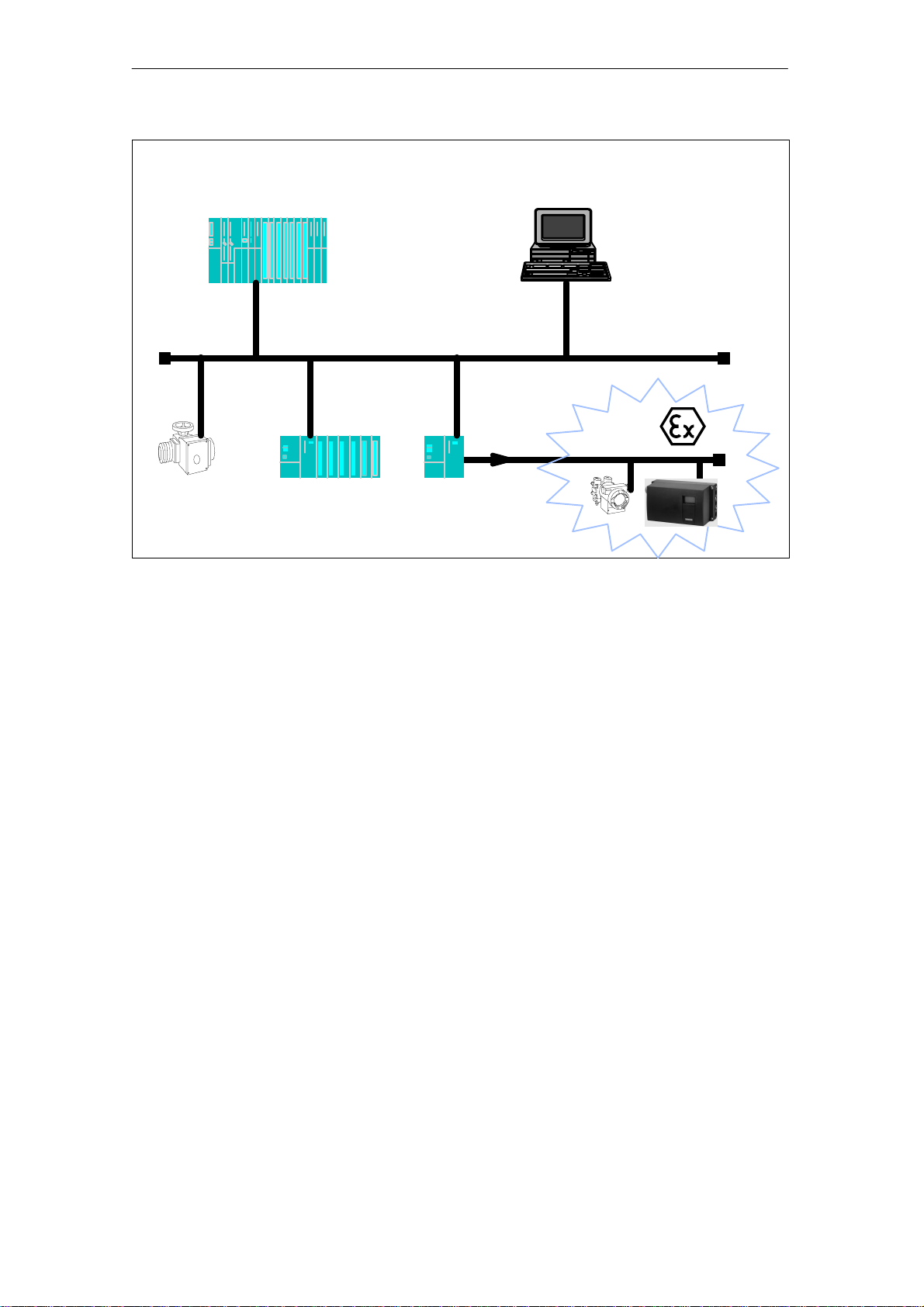
Master
(class 1)
PROFIBUS DP
Slaves
(field devices, distributed I/Os, lower–level controls,
gateway to PROFIBUS P A)
Fig. 1-1 Typical PROFIBUS automation system
Fig. 1-1 shows a section of a typical PROFIBUS automation system.
The control system consists of two masters with distributed tasks:
Master
(class 2)
PROFIBUS P A
J
The master class 1 performs open–loop and closed–loop control tasks,
master class 2 is used for HMI functions. Exchange of measuring and
positioning data is performed cyclically between master 1 and the field
devices. Parallel with this data, the status information of the field devices is transmitted and evaluated in master 1. Parameterization of the
field devices or reading of further device information is not performed in
cyclic operation.
The control system obtains the information required to establish communication from the device–specific device master data files GSD (see
Appendix).
In addition to cyclic operation one or more masters of class 2 can access the field devices non–cyclically. By this method of communication,
further information can be fetched from the devices or settings made in
the devices.
1.2.2 Properties of the PROFIBUS PA
The PROFIBUS PA permits bidirectional communication from a bus
master with the field devices via a shielded, twisted pair. At the same
time the two–wire field devices are powered via the same lines
(current J in Fig. 1-1).
1-4
Positioner SIP ART PS2/SIPART PS2 PA
C79000-G7476-C150–01
Introduction
Profiles
PLS, PC
In addition to the EN standard 50170, the PNO (PROFIBUS user organization) has defined the functionality of the individual field device types
in a profile description. These profiles define minimum functional requirements and optional extensions. The device–internal ”device management” provides the configuration tool of the control system with all
basic information necessary to locate the profile parameters. In that
way, one parameterizing tool can operate all profile–compliant devices,
whatever their type or manufacturer.
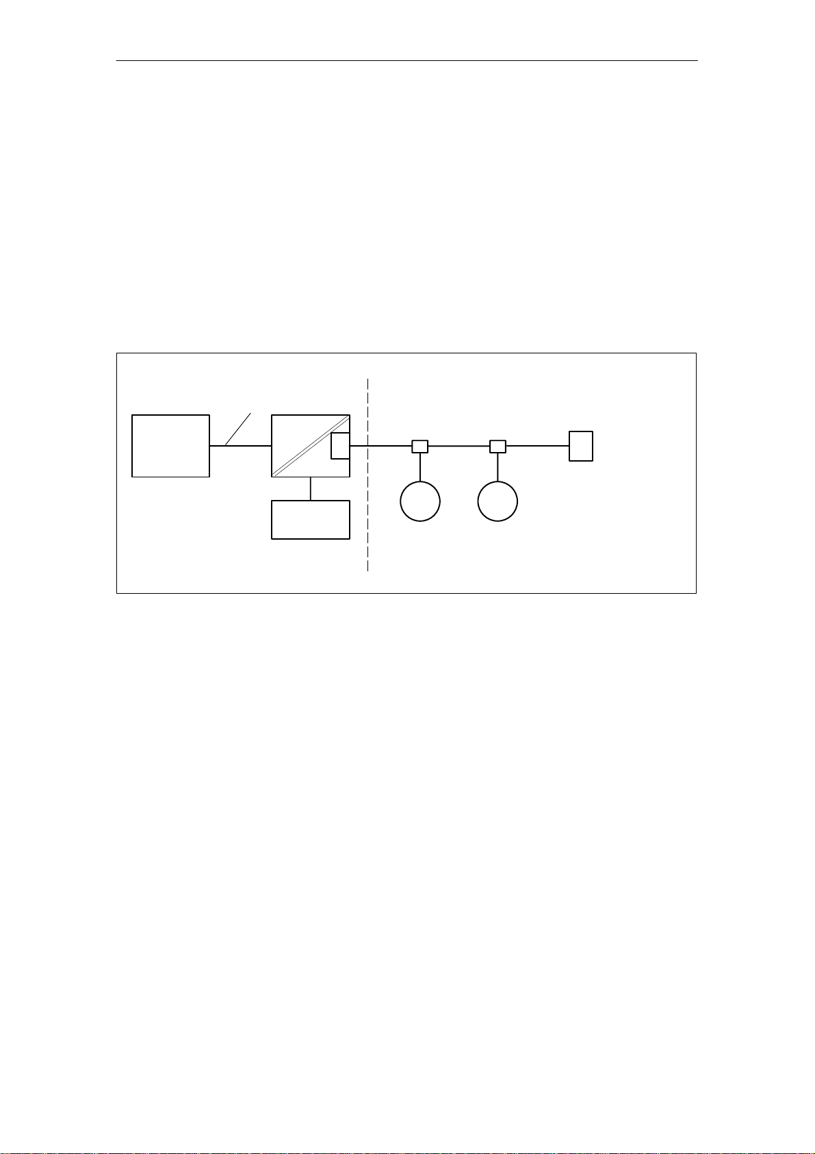
The system must be implemented with one or more PROFIBUS PA
trains depending on the automation task and therefore the number of
field units and the required time response. One PROFIBUS PA train
consists of the components shown in Fig. 1-2.
Control room Field
PROFIBUS DP
Coupler
T
Power
supply
PROFIBUS PA
FG FG
T
additional
line termination
Fig. 1-2 PROFIBUS PA architecture
Link
Control is performed by the central process control system PCS or for
low requirements, by a PC. Usually, the functional signal conversion
DP–PA, bus feed, and bus termination are combined into one linking
module. Depending on the number PROFIBUS PA field devices to be
operated in the automation system and the required time response, a
DP/PA coupler or for higher requirements, a more powerful DP/PA link
is used.
For transmission reasons, the bus must also be fitted with a terminating
resistor T at the remote end. If the recommended bus cable is used,
the theoretically possible maximum line length (sum of all line sections)
is 1900 m.
During configuration, the power requirement of the individual stations
and the voltage drop on the cable must also be taken into account. The
individual FG field devices can be connected to almost any point in the
bus system. For further information see the ”PNO–Leitfaden PROFIBUS P A”/1/.
DP/PA couplers or DP/PA links are powered from a power supply unit
with SEL V (safety extra–low voltage). This power supply unit must
have sufficient back–up reserves to provide back–up power during
short power interruptions.
Positioner SIP ART PS2/SIPART PS2 PA
C79000-G7476-C150–01
1-5

Introduction
The maximum number of devices that you can connect to a bus train
depends on the current consumption and the application conditions.
During operation in a safe zone, the couplers or links supply up to 400
mA to the bus.
In zones subject to explosion hazard, intrinsic safety is only ensured if
the maximum power fed into the bus does not exceed certain voltage
and current values.
These are usually:
EEx ia IIC Current I
Warning
!
To power the intrinsically safe PROFIBUS only certified power supply
units (DP/PA couplers or links) must be used. See the Ex conformity
declaration for the requirements (see Assembly and Installation
Instructions).
< 128 mA, voltage U0<15V
S
From the sum of the maximum current consumption of the connected
devices (acc. to standard = 10 mA per device) and the available current, it is possible to calculate the number of devices that can be connected to a bus train. For safety reasons, a current reserve must be
planned because otherwise there is a risk that a defective device could
overload the bus by increased current consumption and that therefore
the power supply and communication with all the other non–defective
stations could collapse. The size of the required reserve depends on
the current increase in case of fault stated by the device manufacturer.
The electronic current limitation additionally installed in the SIPART
PS2 with PROFIBUS P A ensures a maximum increase of the current
consumption by 3 mA for a defective device.
In order to distinguish the connected process devices from one
another, each device has its own address. The address setting is described in Section 3.6 ”Commissioning”.
For more detailed information about the components, assembly guidelines and configuration, see the technical description of the field
technology package /2/.
1-6
Positioner SIP ART PS2/SIPART PS2 PA
C79000-G7476-C150–01
Introduction
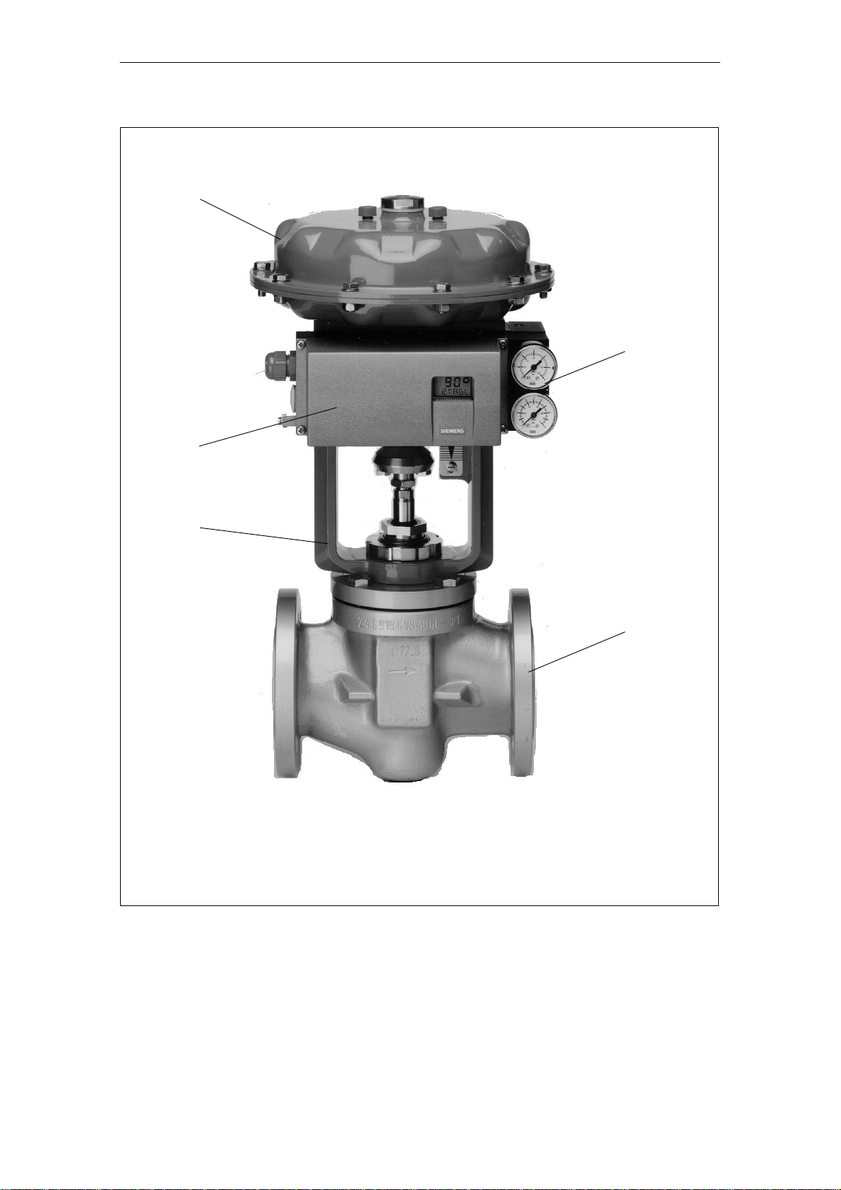
1
4
2
3
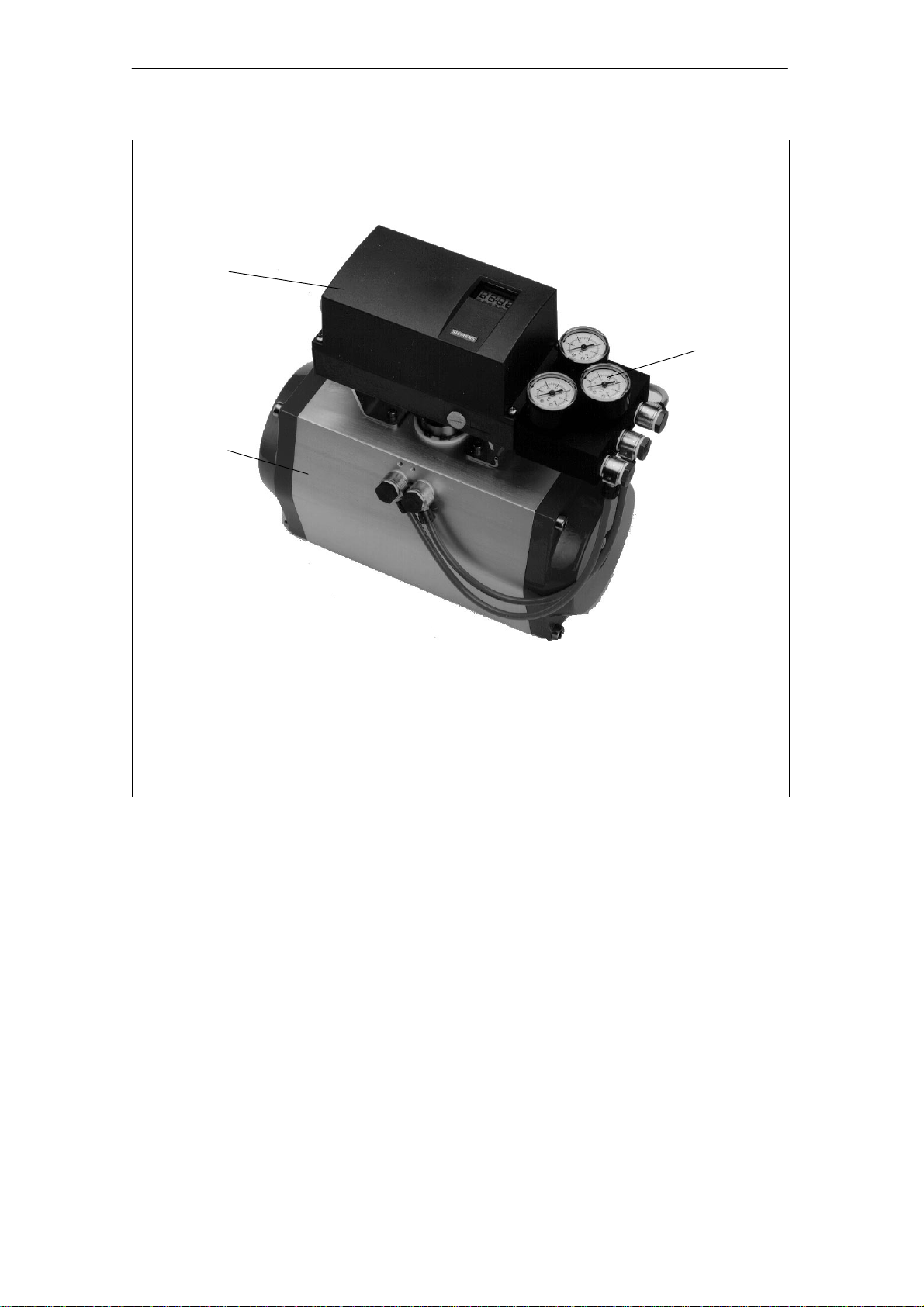
1 Actuator
2 Positioner, single acting in metal housing
3 Intermediate bracket
4 Manometer block, single acting
5 Valve
Fig. 1-3 Positioner mounted on linear actuator (single acting)
5
Positioner SIP ART PS2/SIPART PS2 PA
C79000-G7476-C150–01
1-7
Introduction
1
3
2
1 Positioner, double acting in plastic housing
2 Rotary actuator
3 Manometer block, double acting
Fig. 1-4 Positioner mounted on rotary actuator (double acting)
1-8
Positioner SIP ART PS2/SIPART PS2 PA
C79000-G7476-C150–01

Design and Method of Operation
Design and Method of Operation
This Section describes the mechanical and electrical design, the components of the instrument and the principal method of operation of the
instrument.
2.1 Overview
Introduction
Devices without
PROFIBUS P A
The SIPART PS2 electropneumatic positioner forms a closed-loop control system together with an actuator. The current position of the actuator is acquired via a servo-potentiometer and returned as actual value
x. The setpoint and actual values are output simultaneously on the display.
Setpoint w is formed by a current fed to the SIPART PS2 positioner
which is also used to power the instrument in 2-wire operations. In
3/4–wire operation the power supply is taken from a 24V power input.
2
Devices with
PROFIBUS P A
The setpoint is supplied to the positioner by the control system digitally
via PROFIBUS P A.
The PROFIBUS PA variant of the SIPART PS differs from previous versions by its bus interface. The basic functions including operation and
display have remained almost unchanged. The interface tasks are performed by function blocks 1 to 6 (see Fig. 2-13).
The positioner functions as a predictive 5-step controller, the output
quantity ±∆y of which is used to operate the integrated control valves
with pulse-width-modulated pulses.
These positioning signals effect differences in pressure in the actuator
chamber(s) and consequently adjustment of the actuators until the system deviation is reduced to zero.
Process operation (automatic and manual mode) and configuring
(structuring, initialization and parameterization) is performed with the
three pushbuttons and the display when the housing cover is removed.
The standard version of the basic instrument also has a binary input
(BE1). This input can also be configured individually and is primarily
intended for blocking operating levels.
Positioner SIP ART PS2/SIPART PS2 PA
C79000-G7476-C150–01
2-1
Design and Method of Operation
The actuator position can be output as 2–wire signal Jy = 4 to 20 mA
using the Jy option module.
The actuator can also be monitored for two programmable limit values.
Limit value alarms are output via the alarm option module that can also
monitor and signal the function of the positioner and the actuator. In
automatic operation the system deviation is monitored as a function of
the actuating time. The three binary outputs are implemented as semiconductor outputs and feature self–annunciation, i.e. the outputs respond even if the auxiliary power or the electronics fails.
Depending on how it is configured, the actuator can be blocked, for example, or put into its final position by an external event via the binary
input (BE2) which is also located on the alarm module.
Devices without
PROFIBUS P A
2.2 Components
1
2
3
4
5
6
7
8
9
10
10
Via the optional HART module it is possible to communicate with the
controller.
90°
33°
89
3
6.1
6
6.2
7
11
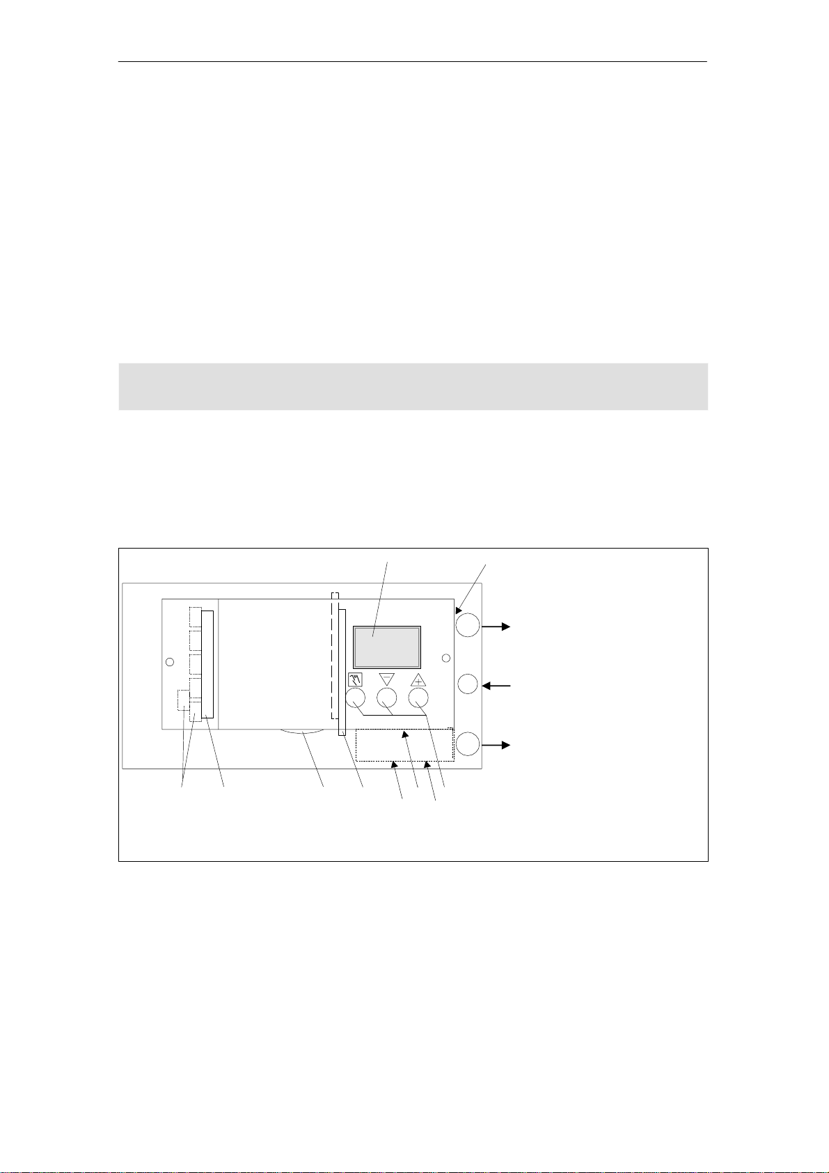
1 Input: inlet air
2 Output: positioning
pressure Y1
3 Display
2
138
4 Output: positioning
pressure Y2
**)
5 Control pushbuttons
6 Restrictor Y1
1
8
6.1 Restrictor Y1
6.2 Restrictor Y2
**)
**)
7 Transmission ratio selector
8 Adjusting wheel clutch
4
238
9 Terminals
Basic instrument
10 Terminals
5
Optional modules
1 1 Purging air selector
**)
for double-acting
actuators
Fig. 2-1 View of the instrument (cover open), devices without PROFIBUS PA
2-2
Positioner SIP ART PS2/SIPART PS2 PA
C79000-G7476-C150–01
Design and Method of Operation
3
11
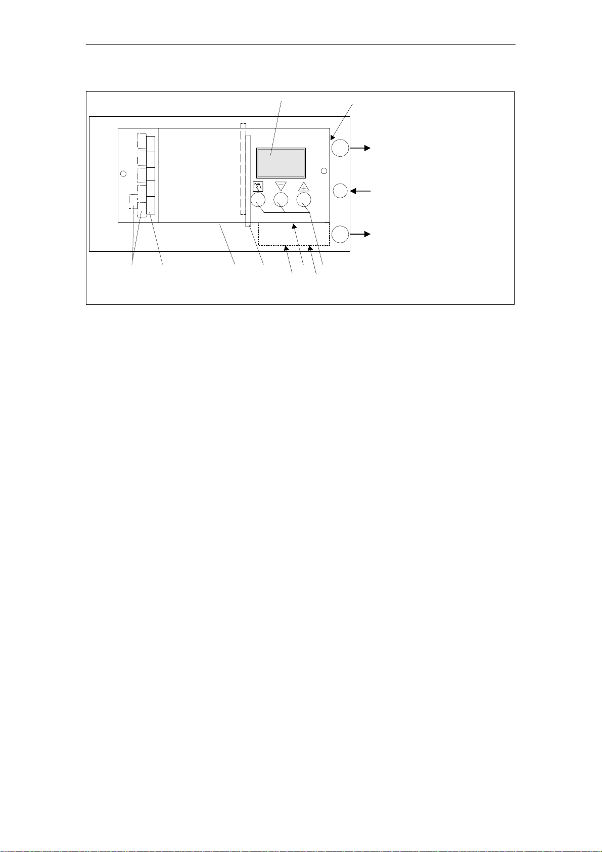
1 Input: inlet air
2 Output: positioning
90°
3
7
9
10
138
8
3 Display
4 Output: positioning
2
5 Control pushbuttons
6 Restrictor Y1
6.1 Restrictor Y1
1
6.2 Restrictor Y2
7 Transmission ratio selector
8 Adjusting wheel clutch
9 Terminals
238
4
10 Terminals
1 1 Purging air selector
**)
for double-acting
10
33°
89
6
7
6.1
5
6.2
actuators
Fig. 2-2 View of the instrument (cover open), devices with PROFIBUS PA
2.2.1 Motherboard
The motherboard contains all electronic elements such as CPU,
memory, ADC. It also contains the display and the control pushbuttons.
pressure Y1
pressure Y2
**)
**)
**)
Basic instrument
Optional modules
The terminal blocks for connecting the option modules are also located
on the motherboard.
2.2.2 Electrical connections
The terminals of the basic instrument, the Jy and the alarm option module are located on the front on the left–hand side and are offset in a
step–shaped arrangement.
A cover protects the modules from being pulled out and prevents incorrect installation.
Positioner SIP ART PS2/SIPART PS2 PA
C79000-G7476-C150–01
2-3

Design and Method of Operation
2.2.3 Pneumatic connections
The pneumatic connections (G1/4) are located on the right-hand side of
the positioner (Fig. 2-3).
Positioning pressure Y1 for single and double–acting actuators
Feedback shaft
Inlet air P
Positioning pressure Y2 for double–acting actuators
Outlet air E with silencer on the underside of the instrument
Fig. 2-3 Pneumatic connection
Z
Two pneumatic connections for the integrated installation of single–acting linear actuators are located on the rear of the positioner:
❑ Positioning pressure Y1
❑ Air outlet E
These connections are locked with screws when supplied (see Fig. 3-2
and Fig. 3-4).
Outlet air E is used to ensure a flow of dry instrument air through the
pick–off area and the spring chamber to prevent corrosion.
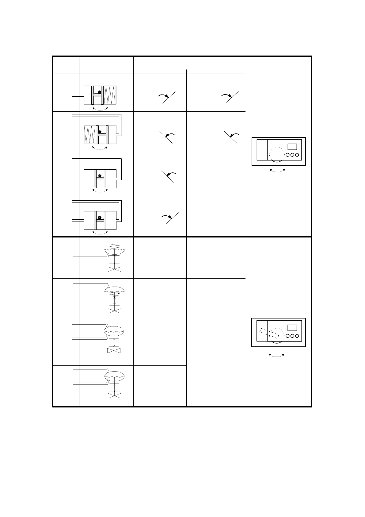
Fig. 2-4 shows pneumatic connection options for various types of actuators with the positioning action and the safety position after auxiliary
power failure.
2-4
Positioner SIP ART PS2/SIPART PS2 PA
C79000-G7476-C150–01
Design and Method of Operation
Positioning
pressure
Connection
Y1
Y1
Y2
Y1
Y1
Y2
Actuator type
OpenClosed
OpenClosed
OpenClosed
OpenClosed
Safety position after auxiliary power failure
electrical pneumatic
Closed Closed
Open Open
Open
Undefined
Closed
On rotary actuators
the counter–clockwise direction of rotation – looking at
the actuating shaft of
the valve – is defined
as “open”
Closed
.
Open
Y1
up
down down
down
Y1
up
down
up up
Y2
Y1
up
down
up
Y1
Y2
up
down
down
Fig. 2-4 Pneumatic connection and positioning action
up down
Undefined
Positioner SIP ART PS2/SIPART PS2 PA
C79000-G7476-C150–01
2-5
Design and Method of Operation
2.2.4 Mounting kit
The positioner can be mounted on nearly all common types of actuators using the appropriate mounting kit.
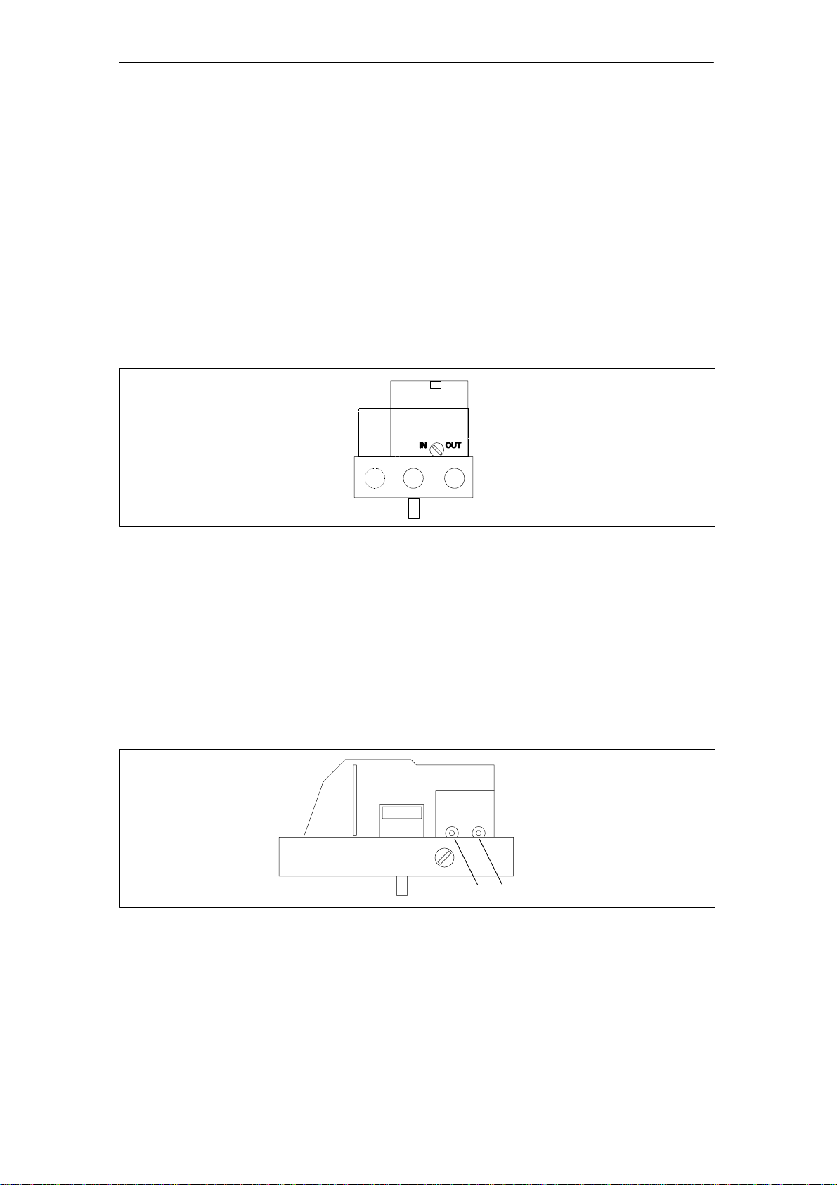
2.2.5 Purging air switchover
The purging air changeover switch above the pneumatic terminal block
(Fig. 2-5) on the valve manifold can be accessed when the housing is
open. When the switch is in position IN the interior of the housing is
purged with very small quantities of clean and dry instrument air. In position OUT the purging air is led directly out of the instrument.
Fig. 2-5 Purging air changeover switch above the pneumatic terminal block, view of the device on the
pneumatic connection side with the cover open
2.2.6 Restrictors
The air flow can be reduced with restrictors Y1 and Y2 (Fig. 2-6) to
achieve actuating times of > 1.5 s on small actuators. Turning the restrictors in the clockwise direction reduces the air flow until it is shut off.
To set the restrictors we recommend closing them first and then opening them again slowly (see Initialization RUN3).
Y1 Y2
Fig. 2-6 Restrictors
2-6
Positioner SIP ART PS2/SIPART PS2 PA
C79000-G7476-C150–01

2.3 Method of operation
The electropneumatic positioner SIPART PS together with the pneumatic actuator forms a control loop in which the actual value x is the position of the actuator rod on linear actuators and the position of the actuator shaft on rotary actuators and the reference variable w is the
actuating current of a controller or manual control station of between
0/4 and 20 mA.
With devices with PROFIBUS PA, the command variable w is set digi-
tally via a bus system.
The stroke or rotational movement of the actuator is transferred to a
servopotentiometer via the necessary mounting accessories, the feedback shaft and reversible gear train without play and then sent to the
analog input of the microcontroller.
This corrects the angular error of the stroke pick–off, if necessary, compares the potentiometer voltage as an actual value x with the setpoint x
fed in via terminals 3 and 7 and calculates the manipulated variable
increments " Dy. Depending on the size and the direction of the system deviation (x–w) the piezoelectric pre–controlled air inlet and air
outlet valve is opened. The volume of the actuator integrates the correcting increments up to actuating pressure y which moves the actuator rod or the actuator shaft approximately proportionally. These correcting increments continue to change the actuating pressure until the
system deviation is zero.
Design and Method of Operation
☞
The pneumatic actuators are available as single–acting and double–acting versions. In the single–acting version only one volume is ventilated
or vented. The resulting pressure is exerted against a spring. In the
double–acting version two volumes act against each other. One volume
is ventilated as the other volume is vented. See block diagrams in Fig.
2-7 and 2-9.
The control algorithm is an adaptive predictive five–point controller.
The valves are actuated with a maintained contact for large system
deviations (high–speed zone). The valves are actuated with pulse–
width–modulated pulses for medium system deviations (short–step
zone).
No positioning pulses are output in the zone of low system deviation
(self-adjusting dead band). The dead-band adaptation and the continual
adaptation of the minimum pulse length in automatic operation allow
the best possible control accuracy to be achieved with the minimum
switching frequencies. The start parameters are determined during the
initialization phase.
Figs. 2-7 to 2-10 show the block diagrams for single and double-acting
actuators, in this example on a linear actuator.
Note
When not under power, the air discharge valve is always open.
Positioner SIP ART PS2/SIPART PS2 PA
C79000-G7476-C150–01
2-7
Design and Method of Operation
1
2
E
H+
E
H–
J
+
E
H–
J
w+
1.5 kΩ
3
9.2 V
4
5
6
HART
module
J
w–
J
w–
BE1
BE1
10
40 Ω
7
8
9
#
Basic instrument
A
w
D
Setpoint
BE1
Actual value
A
x=y
D
Positioning
increments
3V
24V
"dy
3V
24V
A1
A2
y
BE2
3V
3V
3V
D
22
21
#
11
12
31
32
41
42
51
52
Alarm module
A
U
U
61
J
62
Jy module
Piezoelectric
pre–control
3/3 way valve
Y1
Outlet air
E
Y1
138
PZ
Inlet air
8
manometer block
Positioning pressure Y1
up
down
Option
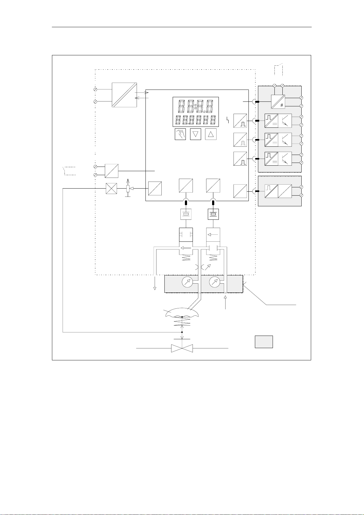
Fig. 2-7 Block diagram diagram for single-acting actuators (2-wire operation, state as supplied), devices
without PROFIBUS PA
2-8
Positioner SIP ART PS2/SIPART PS2 PA
C79000-G7476-C150–01
Design and Method of Operation
Bus interface
BE1
BE1
10
Bus coupling
3
7
9
#
Piezoelectric
pre–control
Basic instrument
w
Setpoint
BE1
Actual value
A
x=y
D
3/3 way valve
Positioning
increments
3V
24V
"dy
3V
24V
A1
A2
y
BE2
3V
3V
3V
D
22
21
#
Alarm module
A
U
U
Jy module
11
12
31
32
41
42
51
52
61
J
62
Y1
Outlet air
E
Y1
138
Positioning pressure Y1
up
down
PZ
8
Inlet air
manometer block
Option
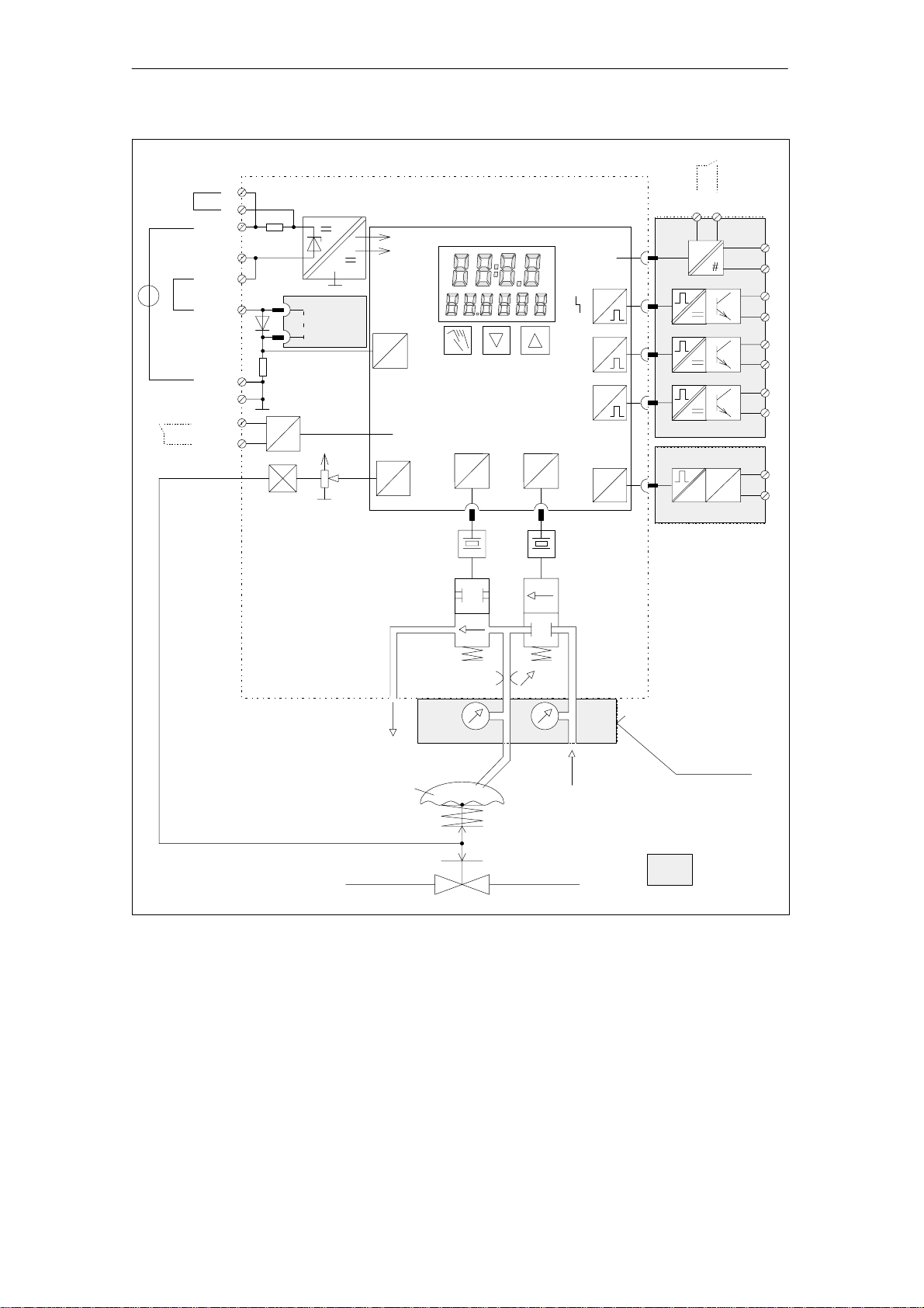
Fig. 2-8 Block diagram diagram for single-acting actuators (2-wire operation, state as supplied), devices
with PROFIBUS PA
Positioner SIP ART PS2/SIPART PS2 PA
C79000-G7476-C150–01
2-9
Design and Method of Operation
1
2
10
1.5 kΩ
3
9.2 V
4
5
6
40 Ω
7
8
9
#
E
H+
E
H–
J
E
+
H–
J
w+
J
w–
J
w–
BE1+
BE1–
Basic instrument
HART
module
A
w
D
Setpoint
BE1
Actual value
x=y
A
D
Positioning
increments
3V
24V
"dy
3V
24V
A1
A2
y
BE2
3V
3V
3V
D
21 22
#
#
11
12
31
32
41
42
51
52
Alarm module
A
U
U
61
62
J
Jy module
Piezoelectic
pre–control
Outlet air
E
Y2
Y2
4/3 way valve
Positioning
Y1
138
Y1
PZ
Inlet air
8
manometer block
pressure Y1
Positioning
up
pressure Y2
down
Option
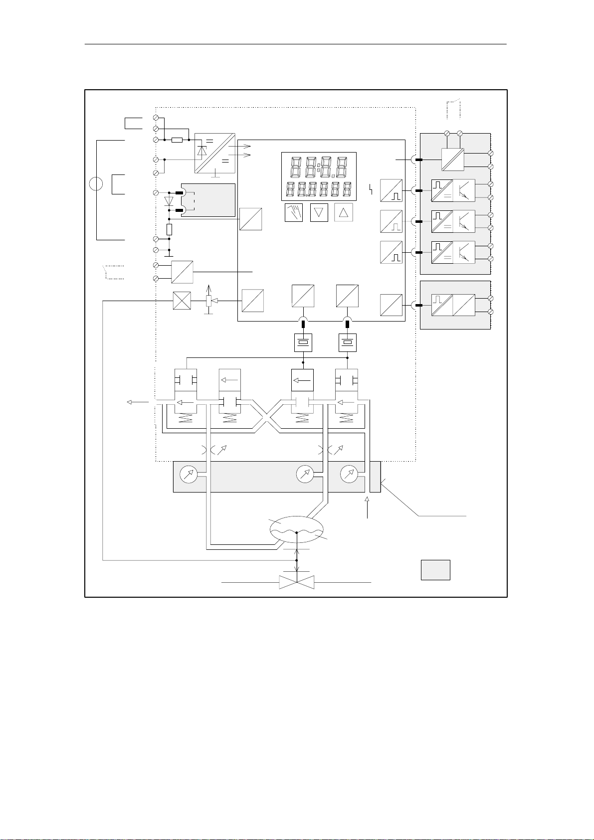
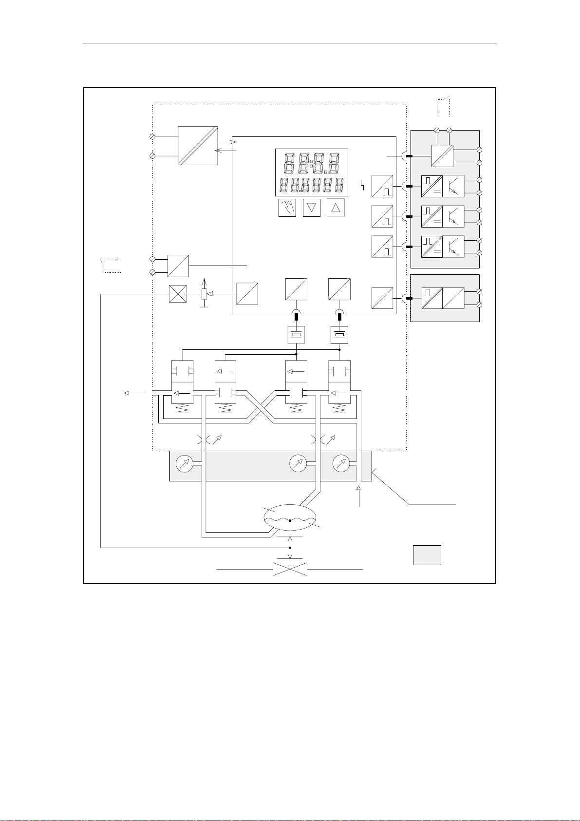
Fig. 2-9 Block diagram for double-acting actuators (2-wire operation, state as supplied), devices with-
out PROFIBUS PA
2-10
Positioner SIP ART PS2/SIPART PS2 PA
C79000-G7476-C150–01
Design and Method of Operation
Bus interface
BE1
BE1
Outlet air
10
Bus coupling
3
7
9
#
Setpoint
Actual value
Piezoelectic
pre–control
Basic instrument
w
BE1
x=y
A
D
Positioning
increments
3V
24V
"dy
3V
24V
A1
A2
21 22
BE2
3V
3V
3V
y
D
A
#
#
Alarm module
U
U
module
J
y
11
12
31
32
41
42
51
52
61
62
J
E
Y2
Y2
238
4/3 way valve
Positioning
pressure Y1
Y1
Y1
138
Positioning
up
pressure Y2
down
PZ
8
Inlet air
manometer block
Option
Fig. 2-10 Block diagram for double-acting actuators (2-wire operation, state as supplied), devices with
PROFIBUS PA
Positioner SIP ART PS2/SIPART PS2 PA
C79000-G7476-C150–01
2-11

Design and Method of Operation
Bus
interface
12 3 4 5 6
Fig. 2-1 1 Block diagram of the bus coupling unit, devices with PROFIBUS PA
Devices with
PROFIBUS P A
1. The EMC filter prevents malfunctions due to electromagnetic
interference.
2. The reverse polarity protection permits connection of the bus cables
in any way and makes installation errors almost impossible.
3. The electronic protection ensures that no impermissibly high current
flows in the event of a fault. That avoids overloading the bus, but
data exchange between the remaining stations not subject to
interference is still possible.
4. The bus interface contains the transmit and receive circuits for the
bus system and the control for the auxiliary power generation.
5. The device internal electronics are isolated by galvanic isolation
from the PROFIBUS PA.
6. The microprocessor interprets the bus commands, initiates device
internal actions and provides position signals, status, and device
data on the bus.
MC
2.4 State as supplied
In the state as supplied no mechanical mounting components are attached to the positioner. These have to be ordered and mounted for the
specific application in accordance with the “Assembly and Installation
Instructions”.
The connections for single and double-acting versions are prepared in
the factory as ordered.
The pneumatic connections on the rear are closed.
2.5 Optional modules
The optional modules are protected and mechanically fixed by a module cover ((1), see Fig. 2-12)
☞
Note
To install the option modules you must first open the housing. As long
as the instrument is open, degree of protection IP65 is not ensured.
2-12
Positioner SIP ART PS2/SIPART PS2 PA
C79000-G7476-C150–01
 Loading...