

Page 1
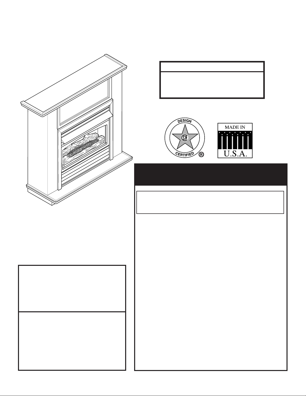
VENT-FREE HEARTH HEATER
OWNER’S OPERATION AND INSTALLATION MANUAL
DHHP/NT
Natural Gas or Propane/LPG
15,000 to 30,000 Btu/Hr
with Thermostat
Shown with Optional Mantel
Which Features a Built-In Base
Warning: This is an unvented gasfired heater. It uses air (oxygen)
from the room in which it is installed.
Provisions for adequate combustion
and ventilation air must be provided.
See page 8.
This appliance may be installed in
an aftermarket, permanently located,
manufactured (mobile) home, where
not prohibited by local codes.
This appliance is only for use with
the type of gas indicated on the rating
plate. This appliance is not convertible
for use with other gases.
WARNINGS
If the information in this manual is not followed exactly,
a fire or explosion may result causing property damage,
personal injury or loss of life.
– Do not store or use gasoline or other flammable
vapors and liquids in the vicinity of this or any
other appliance.
– WHAT TO DO IF YOU SMELL GAS
• Do not try to light any appliance.
• Do not touch any electrical switch; do not use any
phone in your building.
• Immediately call your gas su p p l i e r from a
neighbor's phone. Follow the gas supplier's
instructions.
• If you cannot reach your gas supplier, call the
fire department.
– Installation and service must be performed by
a qualified installer, service agency or the gas
supplier.
Improper installation, adjustment, alteration, service, or
maintenance can cause injury or property damage. Refer
to this manual for correct installation and operational
procedures. For assistance or additional information
consult a qualified installer, service agency, or the gas
supplier.
READ AND SAVE THESE INSTRUCTIONS
Page 2

49D0090 3
CONTENTS
Important Safety Information ..........................3
Specifications ................................................... 5
Local Codes ...................................................... 5
Product Identification ...................................... 6
Safety Device................................................ 6
Piezo Ignition System ................................... 6
Thermostat Heat Control............................... 6
Assembly ......................................................... 6
Installing Hood .............................................. 6
Installing Logs ............................................... 7
Attaching Brass Front Trim ........................... 8
Fresh Air for Combustion and Ventilation ..... 8
Providing Adequate Ventilation ..................... 8
Determining Fresh-Air Flow for Heater
Location ........................................................ 9
Ventilation Air .............................................. 10
Installation ...................................................... 12
Locating Heater........................................... 12
Installation Options ..................................... 13
Connecting to Gas Supply .......................... 17
Operating Instructions................................... 19
For Your Safety Read Before Lighting ........ 19
Lighting Instructions .................................... 20
To Turn Off Gas to Heater........................... 21
Thermostat Control Operation .................... 21
Match Lighting Instructions ......................... 21
Inspecting Heater ........................................... 22
Pilot Flame Pattern ..................................... 22
Burner Flame Pattern.................................. 22
Troubleshooting ............................................. 23
Cleaning and Maintenance ............................ 26
Illustrated Parts List....................................... 27
Accessories .................................................... 28
Warranty.......................................... Back Cover
2 49D0090
Page 3
IMPORTANT SAFETY INFORMATION
INSTALLER
Please leave these instructions with the owner.
OWNER
Please retain these instructions for future reference
.
IMPORTANT
Read this owner’s manual carefully and completely before trying to assemble, operate, or service this heater.
Improper use of this heater can cause serious injury or death from burns, fire, explosion, electrical shock, and
carbon monoxide poisoning.
• Any change to this heater or its controls can be dangerous.
• Improper installation or use of the heater can cause serious injury or death from fire,
burns, explosion or carbon monoxide poisoning.
• Do not allow fans to blow directly into the heater. Avoid any drafts that alter burner
flame patterns. Ceiling fans can create drafts that alter burner flame patterns. Altered
WARNING
burner patterns can cause sooting.
• Do not use a blower insert, heat exchanger insert or other accessory, not approved for
use with this heater where applicable.
CARBON MONOXIDE POISONING: Early signs of carbon monoxide poisoning are similar to the u with headaches,
dizziness and/or nausea. If you have these signs, obtain fresh air immediately. Have the heater serviced as it may not be
operating properly. Get fresh air at once! Have heater serviced. Some people are more affected by carbon monoxide than
others. These include pregnant women, people with heart or lung disease or anemia, those under the inuence of alcohol,
and those at high altitudes.
Propane/LP Gas and Natural Gas: Propane/LP gas and natural gas is odorless. An odor-making agent is added to gas.
The odor helps you detect a gas leak. However, the odor added to gas can fade. Gas may be present even though no odor
exists.
Make certain you read and understand all warnings. Keep this manual for reference. It is your guide to safe and proper
operation of this heater.
1. Due to high temperatures, the appliance should be
located out of trafc and away from furniture and draperies.
2. Surface of heater becomes very hot when running heater.
Keep children and adults away from hot surfaces to avoid
burns or clothing ignition. Heater will remain hot for
a time after shutdown. Allow surfaces to cool before
touching.
3. Carefully supervise young children when they are in the
same room with the apliance.
4. Do not place clothing or other ammable material on
or near the appliance. Never place any objects on the
heater.
5. Make sure screen is in place before running heater.
6. Installation and repair should be done by a qualied
service person.
7. To prevent malfunction and/or sooting, an unvented gas
heater should be cleaned before use at least annually by
a professional service person. More frequent cleaning
may be required due to excessive lint from carpeting,
bedding material, etc. It is imperative that control compartments, burners and circulating air passageways be
kept clean.
8. Keep the appliance area clear and free from combustible
materials, gasoline, and other ammable vapors and
liquids.
Continued on page 4
49D0090 3
Page 4

49D0090 5
IMPORTANT SAFETY INFORMATION
Continued from page 3
10. This appliance is only for use with the type of gas indicated
on the rating plate. This appliance is not convertible for
use with other gases.
11. Do not place propane/LP supply tank(s) inside any structure. Locate propane/ LP supply tank(s) outdoors.
12. If you smell gas
• shut off gas supply
• do not try to light any appliance
• do not touch any electrical switch; do not use any phone
in your building.
• immediately call your gas supplier from a neighbor’s
phone. Follow the gas supplier’s instructions
• if you cannot reachyour gas supplier, call the re depart-
ment
13. This heater shall not be installed in a bedroom or bath-
room.
14. This heater needs fresh, outside air ventilation to run
properly. This heater has an Oxygen Depletion Sensing
(ODS) safety shutoff system. The ODS shuts down the
heater if not enough fresh air is available. See “Air For
Combustion and Ventilation,” pages 8 through 10.
15. Before using furniture polish, wax, carpet cleaner, or
similar products, turn heater off. If heated, the vapors
from these products may create a white powder residue
within burner box or on adjacent walls or furniture.
16. If heater shuts off, do not relight until you provide fresh,
outside air. If heater keeps shutting off, have it serviced.
17. Do not run heater
• where ammable liquids or vapors are used or stored.
• under dusty conditions.
18. Do no t use heater if any part has been under water. Immediately call a qualied service technician to inspect the
room heater and to replace any part of the control system
and any gas control which has been under water.
19. To prevent the creation of soot, follow the instructions in
“Cleaning and Maintenance,” page 26.
23. This unit complies with ANSI Z21.11.2-2001 Unvented
Heaters.
24. Caution: Candles, incense, oil lamps, etc. produce combustion byproducts including soot. Vent-free appliances
will not lter or clean soot produced by these types of
products. In addition, the smoke and/or aromatics (scents)
may be reburnt in the vent-free appliance which can produce odors. It is recommended to minimize the use of
candles, incense, etc. while the vent-free appliance is in
operation.
25. Unvented gas heaters emit moisture into the living area.
In most homes of average construction, this does not pose
a problem. In houses of extremely tight construction,
additional mechanical ventilation is recommended.
26. During manufacturing, fabricating and shipping, various
components of this appliance are treated with certain
oils, lms or bonding agents. These chemicals are not
harmful but may produce annoying smoke and smells
as they are burned off during the initial operation of the
appliance; possibly causing headaches or eye or lung
irritation. This is a normal and temporary occurrence.
The initial break-in operation should last two to three
hours with the burner at the highest setting. Provide
maximum ventilation by opening windows or doors to
allow odors to dissipate. Any odors remaining after this
initial break-in period will be slight and will disappear
with continued use.
27. The appliance and its appliance main gas valve must be
disconnected from the gas supply piping system during
any pressure testing of that system at test pressures in
excess of 1/2 psig (3.5 kPa).
28. The appliance must be isolated from the gas supply
piping system by closing its equipment shutoff valve
during any pressure testing of the gas supply piping
system at test pressures equal to or less than 1/2 psig
(3.5 kPa).
29. This appliance is not a zero clearance replace. Do not
frame this replace into a wall.
20. Turn off and unplug heater and let cool before servicing.
Only a qualied service person should service and repair
heater.
21. Operating heater above elevations of 4,500 feet could
cause pilot outage.
22. To prevent performance problems, do not use a propane/
LP fuel tank of less than 100 lbs. capacity.
4 49D0090
Page 5
SPECIFICATIONS AND LOCAL CODES
NATURAL GAS
NOTE: An external regulator is required to reduce supply pressure to a maximum of 101/2" W.C. on
natural gas systems operating at higher pressure.
Thermostat Pressure
Regulator Pressure Setting: 4" w.c.
Gas Inlet Pressure: 101/2" w.c.
Min. 5" w.c.
PROPANE/LPG
Note: An external regulator is required to reduce supply pressure to a maximum of 13" W.C.
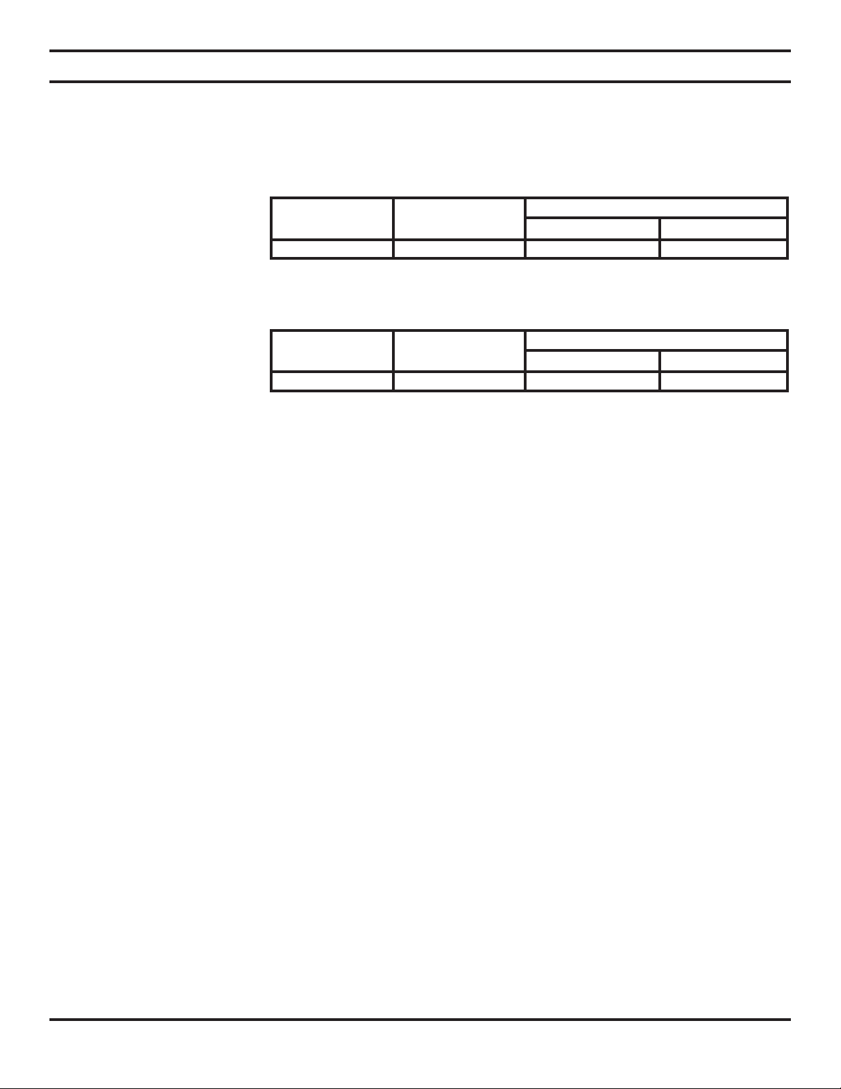
Gas Rate
Model Number Control Max BTU/Hr Min BTU/Hr
DHHNT THERMOSTAT 30,000 15,000
Thermostat Pressure
Regulator Pressure Setting: 10" w.c.
Gas Inlet Pressure: Max. 13" w.c.
Min. 11" w.c.
Gas Rate
Model Number Control Max BTU/Hr Min BTU/Hr
DHHPT THERMOSTAT 30,000 15,000
LOCAL CODES
Follow all local codes. In the absence of local codes, use the latest edition of The National Fuel Gas Code, ANS Z223.1, also
known as NFPA 54. Available from:
American National Standards Institute, Inc. National Fire Protection Association, Inc.
1430 Broadway Batterymarch Park
New York, NY 10018 Quincy, MA 0226
49D0090 5
Page 6
49D0090 7
PRODUCT IDENTIFICATION AND ASSEMBLY
SAFETY DEVICE
This heater has a pilot with an Oxygen Depletion Sensing
(ODS) safety shutoff system. The ODS/pilot is a required
feature for vent-free room heaters. The ODS/pilot shuts
off the heater if there is not enough fresh air.
PIEZO IGNITION SYSTEM
This heater has a piezo ignitor. This system requires no
matches, batteries, or other sources to light heater.
THERMOSTAT HEAT CONTROL
This heater has a thermostat sensing bulb and a control
valve. This results in the greatest heater comfort. This
can also result in lower gas bills.
NOTE: Do not remove Lighting and Warning
Plates from heater.
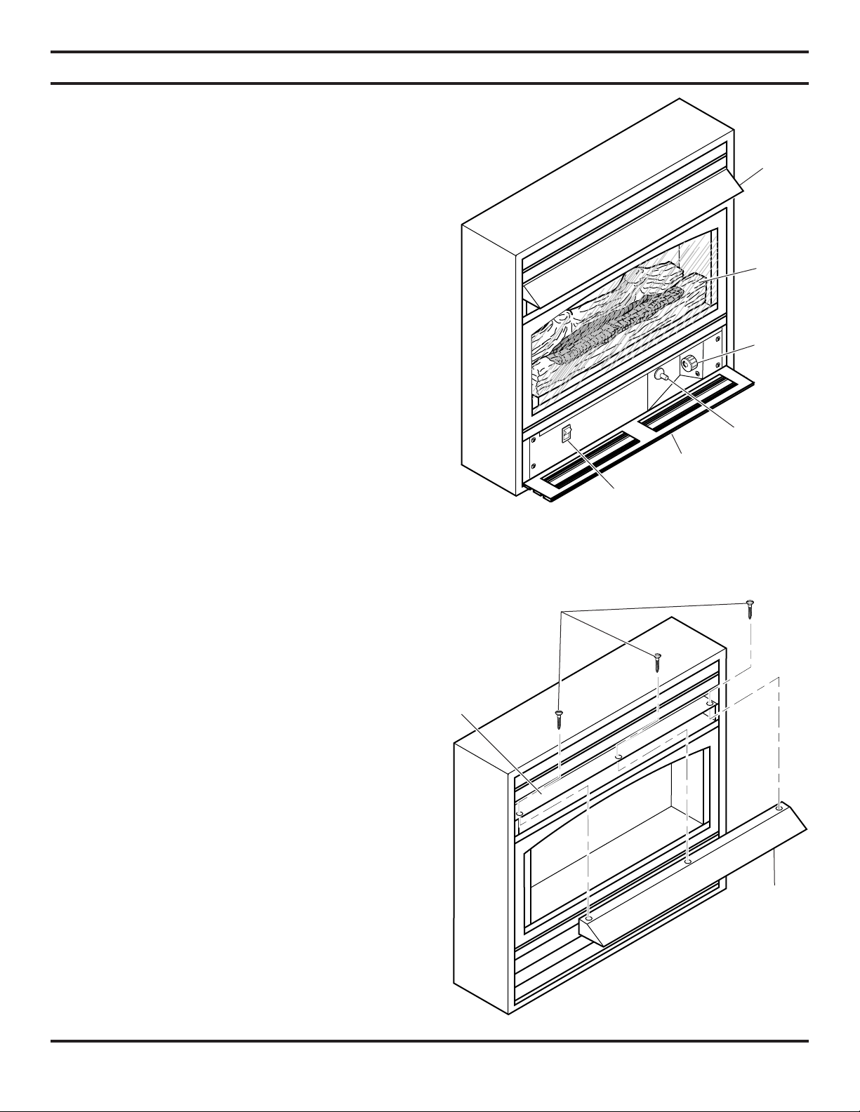
Hood
Screen
Control
Knob
UNPACKING
1. Remove heater from carton.
2. Remove all protective packaging applied to heater
for shipment.
3. Make sure your heater includes the following:
trim
hood
mounting bracket
hardware package which includes:
two (2) 90° angled brackets and shims
four (4) trim screws
three (3) hood screws
two (2) wall mounting screws
two (2) wall spacers
4. Check heater for any shipping damage. If heater is
damaged, promptly inform dealer where you bought
heater.
ASSEMBLY
INSTALLING HOOD
Piezo
Ignitor
Door
Optional Blower
On/Off Switch
Figure 1 - Vent-Free Gas Log Space Heater
Screws
Deflector
1. Remove hood from protective package.
2. Locate three (3) black sheet metal screws inside homeowner’s manual pack.
3. Place hood on deector and line up holes (see Figure 2).
4. Secure hood to deector with three (3) black sheet metal
screws.
NOTE: Side of hood should be on the outside flange
of deflector.
6 49D0090
Figure 2 - Installing Hood
Hood
Page 7
ASSEMBLY
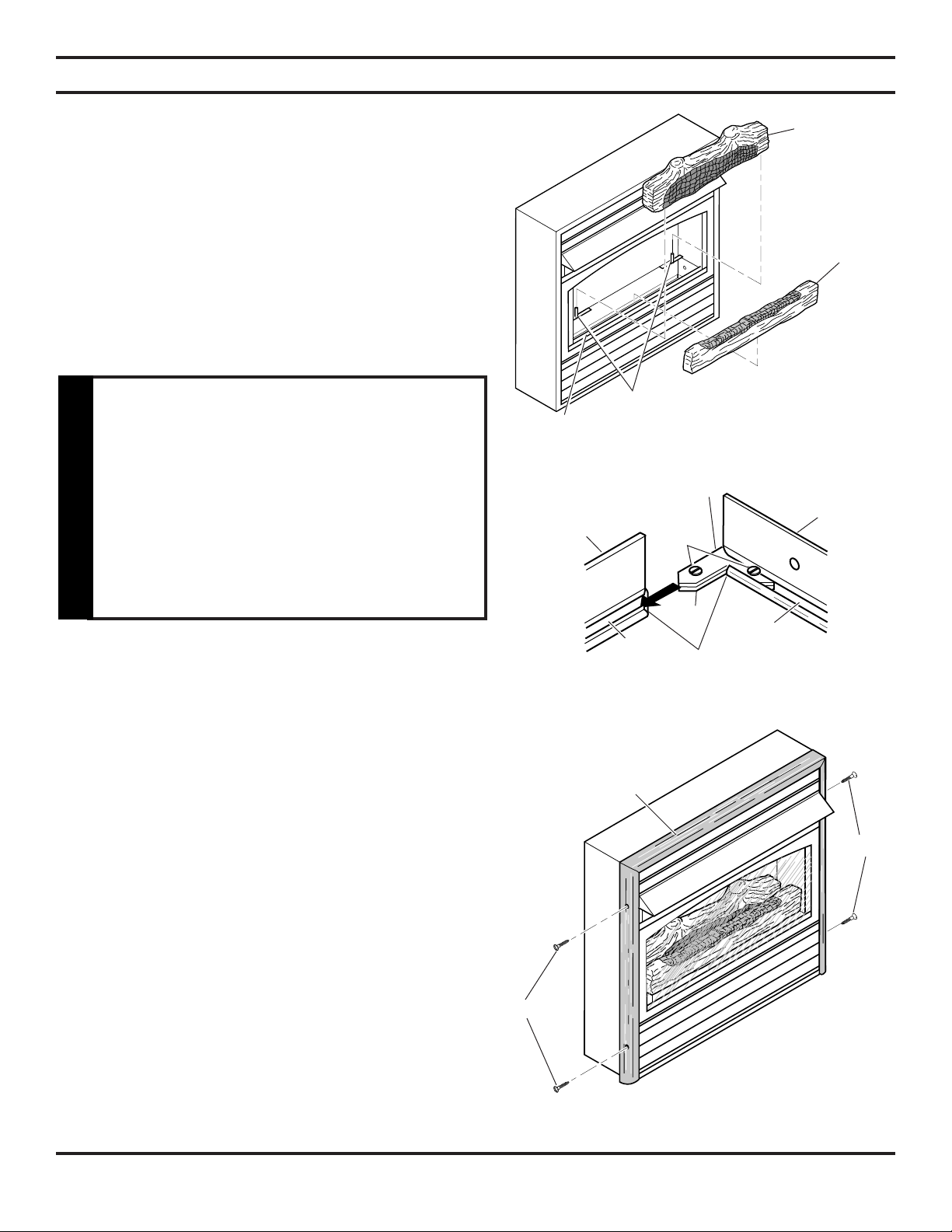
INSTALLING LOGS
NOTE: For easier installation, lay heater on its back.
1. Slide screen up to remove.
2. Remove log from inside of base. Discard protective packaging.
3. Gently slide log on log retaining pin on base assembly (see
Figure 3). The log should t rmly against bottom of log
retaining pin.
4. Place front log in front of burner and behind burner shield.
5. Reattach screen.
WARNING: Always have burner shield
and screen in place before operating
heater. This prev ents excessi ve
temperatures on heater.
Failure t o position t he parts in
accordance with these diagrams or
WARNING
failure to use only parts specifically
approved with this heater may result in
property damage or personal injury.
ATTACHING BRASS FRONT TRIM TO
FRONT PANEL
If any part or parts are missing, contact dealer where you bought
the heater.
Burner
Shield
Side
Brass Trim
Figure 4 - Assembling Bras Trim
Back
Log
Pins
Figure 3 - Installing Logs
Adjusting
Plate
Set
Screws
Shim
Slot
Mitered
Edges
Top Brass
Slot
Front
Log
Trim
1. Remove brass trim from protective packaging. Remove two
(2) 90°-angled mounting brackets and two (2) 90°-angled
shims.
2. Lay trim on the oor face down. Line up the corners with the
top trim at the top and the side trims on the sides.
3. Slide one (1) 90°-angled bracket (with attached screws) and
one (1) 90°-angled shim in the outside corner slot where the
top and side trims meet. Next, slide another bracket and shim
to the inside corner slot. See Figure 4.
4. Hold the corners together securely. Tighten screws on both
brackets with at head screwdriver. Make sure the corners
are ush and there are no spaces.
5. Repeat steps 2 through 4 for other side trim.
7. Place the assembled trim on front of heater cabinet. Attach
on top and sides with four brass screws included in hardware
package. See Figure 5.
49D0090 7
Screws
Assembled
Brass Trim
Screws
Figure 5 - Attaching Brass Trim to Heater
Page 8

49D0090 9
FRESH AIR FOR COMBUSTION AND VENTILATION
WARNING: This heater shall not be installed in a confined space or unusually tight
construction unless provisions are provided for adequate combustion and ventilation
air. Read the following instructions to insure proper fresh air for this and other fuelburning appliances in your home.
WARNING
Today’s homes are built more energy efcient than ever. New materials, increased insulation, and new construction methods
help reduce heat loss in homes. Home owners weather strip and caulk around windows and doors to keep the cold air out
and the warm air in. During heating months, home owners want their homes as airtight as possible.
While it is good to make your home energy efcient, your home needs to breathe. Fresh air must enter your home. All fuelburning appliances need fresh air for proper combustion and ventilation.
Exhaust fans, replaces, clothes dryers, and fuel burning appliances draw air from the house to operate. You must provide
adequate fresh air for these appliances. This will insure proper venting of vented fuelburning appliances.
PROVIDING ADEQUATE VENTILATION
The following are excerpts from National Fuel Gas Code, NFPA 54/ANSI Z223.1, Section 5.3, Air for Combustion and
Ventilation. All spaces in homes fall into one of the three following ventilation classications:
1. Unusually Tight Construction
2. Unconned Space
3. Conned Space
The information on pages 9 and 10 will help you classify your space and provide adequate ventilation.
UNUSUALLY TIGHT CONSTRUCTION
The air that leaks around doors and windows may provide enough fresh air for combustion and ventilation. However, in
buildings of unusually tight construction, you must provide additional fresh air. Unusually tight construction is dened as
construction where:
a. walls and ceilings exposed to the outside atmosphere have a continuous water vapor retarder with a rating
of one perm (6x10-11 kg per pa-sec-m2) or less with openings gasketed or sealed and
b. weather stripping has been added on openable windows and doors and
c. caulking or sealants are applied to areas such as joints around window and door frames, between sole
plates and floors, between wall-ceiling joints, between wall panels, at penetrations for plumbing, electrical,
and gas lines, and at other openings.
If your home meets all of the three criteria above, you must provide additional fresh air. See “Ventilation Air From Outdoors,” page 10.
If your home does not meet all of the three criteria above, proceed to “Determining Fresh- Air Flow For Heater Location,”
page 9.
CONFINED AND UNCONFINED SPACE
The National Fuel Gas Code, ANSI Z223.1 denes a conned space as a space whose volume is less than 50 cubic feet per
1,000 Btu per hour (4.8 m3 per kw) of the aggregate input rating of all appliances installed in that space and an unconned
space as a space whose volume is not less than 50 cubic feet per 1,000 Btu per hour (4.8 m per kw) of the aggregate input
rating of all appliances installed in that space. Rooms communicating directly with the space in which the appliances are
installed*, through openings not furnished with doors, are considered a part of the unconned space. This heater shall not
be installed in a conned space or unusually tight construction unless provisions are provided for adequate combustion and
ventilation air.
* Adjoining rooms are communicating only if there are doorless passageways or ventilation grills between them.
8 49D0090
Page 9

FRESH AIR FOR COMBUSTION AND VENTILATION
DETERMINING FRESH-AIR FLOW FOR HEATER LOCATION
DETERMINING IF YOU HAVE A CONFINED OR UNCONFINED SPACE
Use this worksheet to determine if you have a conned or unconned space.
Space: Includes the room in which you will install heater plus any adjoining rooms with doorless passageways or ventilation grills between the rooms.
1. Determine the volume of the space (length x width x height).
Length x Width x Height = ____________________ cu. ft. (volume of space)
Example: Space size 20 ft. (length) x 16 ft. (width) x 8 ft. (ceiling height) = 2560 cu. ft. (volume of space)
If additional ventilation to adjoining room is supplied with grills or openings, add the volume of these rooms to the total
volume of the space.
2. Divide the space volume by 50 cubic feet to determine the maximum Btu/Hr the space can support.
_____________________(volume of space) ¸ 50 cu. ft. = (Maximum Btu/Hr the space can support)
Example: 2560 cu. ft. (volume of space)¸ 50 cu. ft. = 51.2 x 1000 = 51,200 (maximum Btu/Hr the space can support)
3. Add the Btu/Hr of all fuel burning appliances in the space.
Vent-free heater _______________ Btu/Hr
Gas water heater* _______________ Btu/Hr
Gas furnace _______________ Btu/Hr
Vented gas heater _______________ Btu/Hr
Gas replace logs _______________ Btu/Hr
Other gas appliances* + _______________ Btu/Hr
Total = _______________ Btu/Hr
Example:
Gas water heater 30,000 Btu/Hr
Vent-free heater + 30,000 Btu/Hr
Total = 60,000 Btu/Hr
* Do not include direct-vent gas appliances. Direct-vent draws combustion air from the outdoors and vents to
the out-doors.
4. Compare the maximum Btu/Hr the space can support with the actual amount of Btu/Hr used.
_________________ Btu/Hr (maximum the space can support)
_________________ Btu/Hr (actual amount of Btu/Hr used)
Example: 51,200 Btu/Hr (maximum the space can support)
60,000 Btu/Hr (actual amount of Btu/Hr used)
The space in the above example is a conned space because the actual Btu/Hr used is more than the maximum Btu/Hr the
space can support. You must provide additional fresh air. Your options are as follows:
A. Rework worksheet, adding the space of an adjoining room. If the extra space provides an unconned space, remove
door to adjoining room or add ventilation grills between rooms. See “Ventilation Air From Outdoors,” page 10.
B. Vent room directly to the outdoors. See “Ventilation Air From Outdoors,” page 10.
C. Install a lower Btu/Hr heater, if lower Btu/Hr size makes room unconned.
If the actual Btu/Hr used is less than the maximum Btu/Hr the space can support, the space is an unconned space. You will
need no additional fresh air ventilation.
If the area in which the heater may be operated is smaller than that defined as an
unconfined space or if building is of unusually tight construction, provide adequate
combustion and ventilation air by one of the methods described in the National Fuel
Gas Code, ANSI Z223.1/NFPA 54, Section 5.3 or applicable local codes.
WARNING
49D0090 9
Page 10
49D0090 11
FRESH AIR FOR COMBUSTION AND VENTILATION
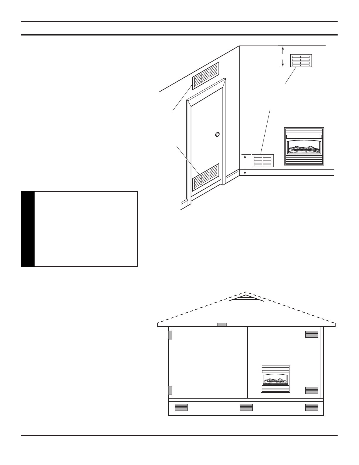
VENTILATION AIR
FROM INSIDE BUILDING
This fresh air would come from an adjoining
unconfined space. When ventilating to an
adjoining unconned space, you must provide
two permanent openings: one within 12" of the
ceiling and one within 12" of the oor on the
wall connecting the two spaces (see options 1
and 2, Figure 6). You can also remove door
into adjoining room (see option 3, Figure 6).
Follow the National Fuel Gas Code, NFPA 54/
ANSI Z223.1, Section 5.3, Air for Combustion
and Ventilation for required size of ventilation
grills or ducts.
Option 1:
Ventilation
Grills into
Adjoining
Room
Option
3:
Remove
Door into
Adjoining
Room
Option 2:
Ventilation Grills into
Adjoining Rooms
Rework worksheet, adding
the space of the adjoining
unconfin ed spa ce. Th e
combine d spaces m ust
have enough fresh air to
supply all appliances in
WARNING
both spaces.
VENTILATION AIR FROM OUTDOORS
Provide extra fresh air by using ventilation
grills or ducts. You must provide two permanent openings: one within 12" of the ceiling
and one within 12" of the oor. Connect these
items directly to the outdoors or spaces open to
the outdoors. These spaces include attics and
crawl spaces. Follow the National Fuel Gas
Code, NFPA 54/ANSI Z223.1, Section 5.3, Air
for Combustion and Ventilation for required
size of ventilation grills or ducts.
IMPORTANT: Do not provide openings
for inlet or outlet air into attic if attic has a
thermostat-controlled power vent. Heated
air entering the attic will activate the power
vent.
Outlet
Air
Outlet
Air
Figure 6 - Ventilation Air from Inside Building
Outlet
Inlet Air
Figure 7 - Ventilation Air from Outdoors
Ventilated
Attic
Air
To Attic
To
Crawl
Space
Ventilated
Crawl Space
10 49D0090
Page 11

This heater is intended for use as supplemental heat. Use this heater along with your
primary heating system. Do not install this heater as your primary heat source. If you
have a central heating system, you may run system’s circulating blower while using
heater. This will help circulate the heat throughout the house. In the event of a power
NOTICE
outage, you can use this heater as your primary heat source.
A qualified service person must install
heater. Follow all local codes.
WARNING
INSTALLATION ITEMS
Before installing heater, make sure you have the items listed below.
INSTALLATION
CHECK GAS TYPE: The gas supply
must be the same as stated on the
heater’s rating plate. If the gas supply
is different, DO NOT INSTALL THE
HEATER. Contact your dealer for the
CAUTION
correct model.
• external regulator (supplied by installer for propane/LPG and 1/2 lb. natural gas systems)
• piping (check local codes) • pipe wrench • tee joint
• sealant (resistant to propane/LP gas) • equipment shutoff valve* • ground joint union
* A CSA design-certied equipment shutoff valve with 1/8” NPT tap is an acceptable alternative to test gauge connec-
tion. Purchase the optional CSA design-certied equipment shutoff valve from your dealer.
49D0090 11
Page 12

49D0090 13
INSTALLATION
LOCATING HEATER
Maintain the minimum clearances shown in
Figure 8. If you can, provide greater clearances
from floor, ceiling, and joining wall.
WARNING
You can locate heater on oor with optional heart base. The heater can also be installed into an optional decorative mantel
(some mantels require the hearth base).
IMPORTANT: Only use optional mantels and hearth base specified in this manual. Purchase the optional mantel
and hearth base from your dealer. See “Accessories,” pages 28 and 29.
The heater may also be mounted on a wall. Optional mantel cannot be used if mounting heater on a wall.
Figure 8 - Mounting Clearances As Viewed From Front of Heater
12 49D0090
Page 13

INSTALLATION
Never install the heater
• in a bedroom or a bathroom • in a
recreational vehicle • where curtains,
furniture, clothing, or other flammable
objects are less than 36 inches from
the front, top, or sides of the heater
• as a fireplace insert
WARNING
• in high traffic areas
This heater creates warm air currents.
These currents move heat to wall
surfaces next to heater. Installing
heater next to vinyl or cloth wall
coverings or operating heater where
impurities (such as tobacco smoke,
aromatic candles, cleaning fluids,
CAUTION
oil or kerosene lamps, etc.) in the air
exist, may discolor walls.
• in windy or drafty areas
IMPORTANT: Vent-free heaters add moisture to the air. Although this is beneficial, installing heater in rooms
without enough ventilation air may cause mildew to form from too much moisture. See Fresh Air for Combustion
and Ventilation, pages 8 through 10.
For convenience and efciency, install heater
If you install the heater in a home
garage
• heater pilot and burner must be at
least 18 inches above floor.
• locate heater where moving vehicle
CAUTION
will not hit it.
• where there is easy access for operation, inspection, and
service.
• in coldest part of room.
An optional fan kit is available from your dealer. See
“Accessories,” pages 28 and 29. If planning to use fan,
locate heater near an electrical outlet.
INSTALLATION OPTIONS
There are three options for mounting this heater.
A. Mounting heater to wall
B. Mounting heater to optional hearth base
C. Mounting heater to optional mantel (some mantels require the hearth base)
Continued
49D0090 13
Page 14

49D0090 15
INSTALLATION
Continued
A. MOUNTING HEATER TO WALL
Mounting Bracket
The mounting bracket is located in the package tray (see Figure 9). Remove mounting bracket from tray.
Only use last hole on each end of mounting bracket to attach bracket to wall. These two holes are 16 inches apart from their
centers (see Figure 9). Attach mounting bracket to wall studs. This method provides the strongest hold. Insert mounting
screws through mounting bracket and into wall studs.
Mounting
Marking Screw Locations
1. Tape mounting bracket to wall where heater will be located.
Make sure mounting bracket is level.
Bracket
Maintain minimum clearances shown
in Figure 9. If you can, provide greater
clearances from floor and joining wall.
WARNING
2. Mark screw locations on wall (see Figure 9).
Note: Only mark last hole on each end of mounting
bracket. Insert mounting screws through these
holes only.
3. Remove tape and mounting bracket from wall.
Attaching Mounting Bracket to Wall
Note: Mounting screws and spacers are in hardware package. The hardware package is provided with
heater.
Attaching To Wall Studs
For attaching mounting bracket to wall studs
1. Drill holes at marked locations using 9/64” drill bit.
2. Place mounting bracket onto wall. Line up last hole on each end of bracket with holes drilled in wall.
3. Insert mounting screws through bracket and into wall studs.
4. Tighten screws until mounting bracket is rmly fastened to wall studs.
NOTE: You may mount the unit anywhere on a concrete wall.
Figure 9 - Mounting Bracket Clearances
Attaching Mounting Bracket To Wall
14 49D0090
Page 15

INSTALLATION
Placing Heater on Mounting Bracket
1. Install wall spacers.
2. Attach two (2) rubber bumpers to back of
heater as shown in Figure 10.
3. Locate two (2) horizontal slots on back panel
of heater.
4. Place heater onto mounting bracket. Slide
horizontal slots onto stand-out tabs on mounting bracket.
B. MOUNTING HEATER ON OPTIONAL HEARTH BASE
Tools needed:
• #2 Phillips screwdriver • slotted screwdriver
• electric drill (if securing base to oor)
The optional hearth base kit includes the following:
• Hearth Base • 4 Wood Screws • 4 Sheet Metal Screws
• Hearth Insert • 4 Anchors • 2 Brass Screws • Brass Base Trim
Note: To secure hearth base to floor, follow instructions under “Securing Hearth Base to Floor,” page 16.
If not securing hearth base to floor, proceed to “Mounting Heater to Optional Hearth Base,” page 16.
Stand-Out
Tabs
Horizontal Slots
Mounting
Bracket
(already
attached
to wall)
Rubber
Bumpers
Figure 10 - Mounting Heater Onto
Mounting Bracket
Continued
49D0090 15
Page 16

49D0090 17
INSTALLATION
Continued
Mounting Heater to Optional Hearth Base
1. Lay heater on its back on a table with the
bottom of heater overhanging the edge of
the table.
2. Remove 2 shipping screws in bottom of heater.
Discard shipping screws.
3. Line up mounting holes on top of hearth
base with holes in bottom of heater (see
Figure 11).
4. Using a Phillips screwdriver, secure hearth
base to heater with four sheet metal screws
(see Figure 11).
5. Stand heater up on base.
6. Place hearth insert in hearth base as shown in
Figure 12.
7. Assemble brass trim (see steps 1 through
7 under “Assembling and Attaching Brass
Trim,” page 7).
8. Slide base trim on heater base. Attach brass
trim to base with two brass screws included
as shown in Figure 12.
Bottom of Heater
Shipping Screw
Holes for
Securing Heater
to Floor
Figure 11 - Attaching Heater to Hearth Base
Mounting
Holes
Sheet Metal
Screws
Securing Hearth Base to Floor
1. Position hearth base in desired location. Mark holes for
drilling (See Figure 11). Remove hearth base.
2. For carpeted oor, make a small cut with a sharp knife
at marked locations before drilling. If securing to a
wood oor, drill a 3/4" deep hole using a 1/8" diameter
drill bit. Do not use anchors in wood oors. If securing
to a concrete oor, drill a 1 3/8" deep hole using a 5/32"
diameter concrete drill bit. Completely insert anchors
into each hole.
3. Mount heater to hearth base following steps under
Mounting Heater to Optional Hearth Base. After mounting heater, position heater and hearth base over drilled
holes. With slotted screwdriver, secure hearth base to
oor with four wood screws.
C. MOUNTING HEATER TO OPTIONAL MANTEL.
See Instructions Included With Mantel Kit.
IMPORTANT: Only use the optional mantels specified in this manual. See “Accessories,” pages 28 and 29 for
proper mantel kits. This heater is only approved for use with mantels designed for this heater. Do not use these
mantels with any other product.
Figure 12 - Placing Hearth Insert on Heater
Base and Attaching Brass Base Trim
Screw
Brass Base
Trim
16 49D0090
Page 17

CONNECTING TO GAS SUPPLY
INSTALLATION
This appliance requires a 3/8” NPT
(National Pipe Thread) inlet connection
to the pressure regulator.
WARNING
Never connect heater to private (nonutility) gas wells. This gas is commonly
known as wellhead gas.
WARNING
The installer must supply an external regulator. The external
regulator will reduce incoming gas pressure. You must reduce
incoming gas pressure to between 11 and 14 inches of water
column. If you do not reduce incoming gas pressure, heater
regulator damage could occur. Install external regulator with
the vent pointing down as shown in Figure 13. Pointing the
vent down protects it from freezing rain or sleet.
Use only new, black iron or steel pipe. Internally- tinned copper tubing may be used
in certain areas. Check your local codes. Use pipe of 1/2" or greater diameter to allow
proper gas volume to heater. If pipe is too small, undue loss of pressure will occur.
CAUTION
A qu alified service perso n must
connect heater to gas supply. Follow
all local codes.
WARNING
External
Regulator
Vent
Pointing
Down
Figure 13 - External Regulator with Vent
Pointing Down
Propane/LP
Supply Tank
Installation must include an equipment shutoff valve, union,
Use pipe joint sealant that is resistant
to liquid petroleum (LP) gas.
CAUTION
Apply pipe joint sealant lightly to male threads. This will prevent excess sealant from going into pipe. Excess sealant in pipe
could result in clogged heater valves.
IMPORTANT: Hold pressure regulator with wrench when connecting it to gas piping and/or fittings.
Pipe Coupling
To Gas Log
Set or to Gas
Valve
Locations that the Pressure Tapping
Point May be Installed
Figure 14 - Gas Connection
and plugged 1/8” NPT tap. Locate NPT tap within reach for
test gauge hook up. NPT tap must be upstream from heater
(see Figure 14).
IMPORTANT: Install an equipment shutoff valve in an
accessible location. The equipment shutoff valve is for
turning on or shutting off the gas to the appliance.
Gas Supply Inlet
Shutoff
Valve
Pipe
49D0090 17
Page 18

49D0090 19
INSTALLATION
CHECKING GAS CONNECTIONS
Pressure Testing Gas Supply Piping System
Test Pressures In Excess Of 1/2 PSIG (3.5 kPa)
1. Disconnect appliance with its appliance main gas valve
(control valve) and equipment shutoff valve from gas
supply piping system. Pressures in excess of 1/2 psig will
damage heater regulator.
2. Cap off open end of gas pipe where equipment shutoff
valve was connected.
Test all gas piping and connections
for leaks after installing or servicing.
Correct all leaks at once.
WARNING
Never use an open flame to check
for a leak. Apply a mixture of liquid
soap and water to all joints. Bubbles
3. Pressurize supply piping system by either using compressed
air or opening propane/LP supply tank valve.
4. Check all joints of gas supply piping system. Apply mixture
of liquid soap and water to gas joints. Bubbles forming
show a leak.
5. Correct all leaks at once.
6. Reconnect replace and equipment shutoff valve to gas
supply. Check reconnected ttings for leaks.
Test Pressures Equal To or Less Than 1/2
PSIG (3.5 kPa)
1. Close equipment shutoff valve (see Figure 15).
2. Pressurize supply piping system by either using compressed air or
opening propane/LP supply tank valve.
3. Check all joints from propane/LP supply tank to equipment shutoff
valve (see Figure 15). Apply mixture of liquid soap and water to gas
joints. Bubbles forming show a leak.
forming show a leak. Correct all leaks
at once.
WARNING
Make sure external regulator has
been installed between propane/LP
supply and heater. See guidelines
und “Connecting to Gas Supply,”
CAUTION
page 15.
Open
Equipment
Shutoff
Valve
Closed
4. Correct all leaks at once.
Pressure testing heater gas connections
1. Open equipment shutoff valve (see Figure 15).
2. Open propane/LP supply tank valve.
3. Make sure control knob of heater is in the OFF position.
4. Check all joints from equipment shutoff valve to thermostat gas
valve (see Figure 16). Apply mixture of liquid soap and water to
gas joints. Bubbles forming show a leak.
5. Correct all leaks at once.
6. Light heater (see Operating Heater, pages 19 through 21). Check
all other internal joints for leaks.
7. Turn off heater (see “To Turn Off Gas to Heater,” page 19.
8. Replace front panel.
18 49D0090
Figure 15 - Equipment Shutoff Valve
Thermostat Gas Valve Location
Propane/LP
Supply Tank
Equipment Sutoff
Valve
Figure 16 - Checking Gas Joints
Page 19

OPERATING INSTRUCTIONS
FOR YOUR SAFETY READ BEFORE LIGHTING
A. This appliance is equipped with an ignition device
If you do not follow these instruction
exactly, a fire or explosion may result
causing property damage, personal
injury or loss of life.
WARNING
WHAT TO DO IF YOU SMELL GAS:
• Do not attempt to light any appliance.
• Do not touch any electric switch; do not use any phone in your building.
• Immediately call your gas supplier from a neighbor's phone. Follow the gas supplier's instructions.
• If you cannot reach your gas supplier, call the re department.
C. Use only your hand to push in, or turn the gas control knob. Never use tools. If the knob will not push in or
turn by hand, don't try to repair it. Call a qualied service technician. Force or attempted repair may result
in a re or explosion.
which automatically lights the pilot. If the piezo is not
working properly, see “Match Lighting Instructions,”
page 21.
B. BEFORE OPERATING smell all around the appli-
ance area for gas. Be sure to smell next to the oor
because some gas is heavier than air and will settle on
the oor.
D. Do not use this appliance if any part of it has been under water. Immediately call a qualied service tech-
nician to inspect the appliance and to replace any part of the control system and any gas control that has
been under water.
Control
Knob
Piezo
Door
Ignitor
Optional Blower
On/Off Switch
Figure 17 - Location of Piezo Ignitor and Control Knob
49D0090 19
Page 20

49D0090 21
OPERATING INSTRUCTIONS
LIGHTING INSTRUCTIONS
1. STOP! Read the safety information label.
2. Make sure the manual shutoff valve is fully open.
3. This gas log set is equipped with an ignition device (piezo) which automatically lights the pilot. If piezo
ignitor does not light the pilot, refer to instructions for “Match Lighting Instructions”, page 21.
4. Turn gas control knob clockwise to the OFF position.
5. Wait (5) minutes to clear out any gas. Then smell for gas, including near the oor. If you smell gas,
STOP! Follow the instructions under “What To Do if You Smell Gas,” page 17. If you don't smell gas, go to
next step.
6. From OFF position, turn the gas control knob counterclockwise to PILOT position. Push in control
knob for 5 seconds. See Figure 20. NOTE: If you are running the heater for the first time, it will be
necessary to press in the control knob for 30 seconds or longer to allow air to bleed out
of the gas piping.
7. With control knob pressed in, push down and release ignitor button. This will light pilot. The pilot is attached
to the front of burner. If needed, keep pressing ignitor button until pilot lights. Note: If pilot does not
stay lit, refer to “Troubleshooting,” pages 32 through 25. Also contact a qualified service
person or gas supplier for repairs. Until repairs are made, light pilot with match. To light
pilot with match, see “Match Lighting Instructions,” page 21.
8. Keep control knob pressed in for 30 seconds after lighting pilot. After 30 seconds, release control knob.
• If control knob does not pop up when released, contact a qualied service person or gas supplier for
repairs.
Note: If pilot goes out, repeat steps 4 through 8 . This heater has a safety interlock system. Wait
one (1) minute before lighting pilot again.
9. Turn control knob counterclockwise counterclockwise to desired heating level. The main
burner should light. Set control knob to any heat level between HI and LO. For thermostat operation, see
page 21.
Do not try to adjust heating levels by
using the equipment shutoff valve.
WARNING
Control
Knob
Piezo
Ignitor
Ignitor Electrode
Thermocouple
(NG only)
Thermocouple (LP only)
Pilot Burner
Figure 18 - Control Knob In The OFF Position
20 49D0090
Figure 19 - Pilot
Page 21

OPERATING INSTRUCTIONS
TO TURN OFF GAS TO HEATER
SHUTTING OFF HEATER
1. Turn control knob clockwise to OFF position to completely shut off the heater.
2. If applicable: Turn off all electric power to the heater.
SHUTTING OFF BURNER ONLY (PILOT STAYS LIT)
Turn control knob clockwise to the PILOT position.
THERMOSTAT CONTROL OPERATION
The thermostatic control used on this heater differs from standard thermostats. Standard thermostats simply
turn on and off the burner. The thermostat used on this heater senses the room temperature. The thermostat
adjusts the amount of gas ow to the burner. This increases or decreases the burner ame height. At times the
room may exceed the set temperature. If so, the burner will shut off. The burner will cycle back on when room
temperature drops below the set temperature.
The control knob can be set to any heat level between HI and LO.
Note: The thermostat sensing bulb measures the temperature of air near the heater cabinet.
This may not always agree with room temperature (depending on housing construction,
installation location, room size, open air temperatures, etc.). Frequent use of your heater will
let you determine your own comfort levels.
MATCH LIGHTING INSTRUCTIONS
1. Open lower access door (see Figure 1, page 6).
2. Follow steps 1 through 6 under Lighting Instructions, page 20.
3. With control knob pressed in, strike match. Hold match to pilot until pilot lights.
4. Keep control knob pressed in for 30 seconds after lighting pilot. After 30 seconds, release control knob.
Now follow step 9 under Lighting Instructions, page 20.
5. Close lower access door. Contact your dealer to relace or repair the piezo ignitor.
49D0090 21
Page 22

49D0090 23
INSPECTING HEATER
Check pilot ame pattern and burner ame pattern often.
PILOT FLAME PATTERN
Figure 20 shows a correct pilot ame pattern.
Figure 21 shows an incorrect pilot ame pattern. The incorrect pilot ame is not touching the thermocouple. This will cause
the thermocouple to cool. When the thermocouple cools, the heater will shut down.
If pilot ame pattern is incorrect, as shown in Figure 21
• turn heater off (see “To Turn Off Gas to Appliance,” page 21)
• see “Troubleshooting,” pages 24 through 26
Thermocouple
for Natural
Thermocouple
for LP
Figure 21 - Correct Pilot Flame Pattern
Thermocouple
for Natural
Thermocouple
for LP
Figure 22 - Incorrect Pilot Flame
Pattern Pilot Burner
BURNER FLAME PATTERN
Figure 22 shows a correct burner ame pattern. Figure 23 shows an incorrect burner ame pattern. The incorrect burner
ame pattern shows yellow tipping of the ame. It also shows the ame higher than one inch above the log.
Note: When using the heater the first time, the flame will be opaque orange/yellow for approximately one
hour until the log cures.
If yellow tipping occurs, your heater
could produce increased levels of
carbon monoxide. If burner flame
pattern shows yellow tipping, follow
instructions, bottom of this page.
WARNING
Do not mistake orange flames with
yellow tipping. Dirt or other fine
particles enter the heater and burn
causing brie f patche s of ora nge
NOTICE
flame.
Top of Flame Even
If pilot ame pattern is incorrect, as shown
in Figure 23,
• turn heater off (see “To Turn Off Gas
to Appliance,” page 21)
• see “Troubleshooting,” pages 24
through 26.
Figure 22 - Correct Burner
22 49D0090
with Top of Log
Figure 24 - Incorrect Burner
Flame Pattern
Yellow Tippping
Flame Pattern
Page 23

TROUBLESHOOTING
turn off and unplug heater and let
cool before servicing. Only a qualified
service person should service and
repair heater.
WARNING
OBSERVED
PROBLEM
When ignitor button
is pressed, there is no
spark at ODS/pilot
When ignitor button
is pressed, there is
spark at ODS/pilot but
not ignition
Never use a wire, needle, or similar
object to clean ODS/pilot. This can
damage ODS/ pilot unit.
CAUTION
Note: All troubleshooting items are listed in order of operation.
POSSIBLE CAUSE
1. Ignitor electrode positioned wrong
2. Ignitor electrode broken
3. Ignitor electrode not connected to ignitor cable
4. Ignitor cable pinched or wet
5. Broken ignitor cable
6. Bad piezo ignitor
1. Gas supply turned off or equipment shutoff
valve closed
2. Control knob not in PILOT position
3. Control knob not pressed in while in
PILOT position
4. Air in gas lines when installed
5. Depleted gas supply
6. ODS/pilot is clogged
7. Gas regulator setting is not correct
REMEDY
1. Replace pilot
2. Replace pilot
3. Reconnect ignitor cable
4. Free ignitor cable if pinched by any metal
or tubing. Keep ignitor cable dry
5. Replace ignitor cable
6. Replace piezo ignitor
1. Turn on gas supply or open equipment
shutoff valve
2. Turn control knob to PILOT position
3. Press in control knob while in PILOT
position.
4. Continue holding down control knob. Repeat
igniting operation until air is removed
5. Contact local gas company
6. Clean ODS/pilot (see “Cleaning and
Maintenance,” page 26) or replace ODS/
pilot assembly
7. Replace gas regulator
ODS/pilot lights but
ame goes out when
control knob is released
49D0090 23
1. Control knob not fully pressed in
2. Control knob not pressed in long enough
3. Safety interlock system has been triggered
4. Equipment shutoff valve not fully open
5. Thermocouple connection loose at control
valve
6. Pilot ame not touching thermocouple, which
allows thermocouple to cool, causing pilot
flame to go out. This problem could be
caused by one or both of the following:
A) Low gas pressure
B) Dirty or partially clogged ODS/pilot
7. Thermocouple damaged
8. Control valve damaged
1. Press in control knob fully
2. After ODS/pilot lights, keep control knob
pressed in 30 seconds
3. Wait one minute for safety interlock
system to reset. Repeat ignition operation
4. Fully open equipment shutoff valve
5. Hand tighten until snug, then tighten 1/4
turn more
6. A) Contact local gas company
B) Clean ODS/pilot (see “Cleaning and
Maintenance,” page 26) or replace ODS/
pilot assembly
7. Replace thermocouple
8. Replace control valve
Continued
Page 24

49D0090 25
TROUBLESHOOTING
Continued
OBSERVED
PROBLEM
POSSIBLE CAUSE
REMEDY
Burner does not light
after ODS/pilot is lit
Delayed ignition of
burner
Burner backring
during combustion
Yellow ame during
burner combustion
Slight smoke or odor
during initial operation
1. Burner orice is clogged
2. Burner orice diameter is too small
3. Inlet gas pressure is too low
1. Manifold pressure is too low
2. Burner orice is clogged
1. Burner orice is clogged or damaged
2. Burner damaged
3. Gas regulator defective
1. Not enough air
2. Gas regulator defective
1. Residues from manufacturing processes
1. Clean burner (see “Cleaning and Mainte-
nance,” page 26) or replace burner orice
2. Replace burner orice
3. Contact local gas company
1. Contact local gas company
2. Clean burner (see “Cleaning and Mainte-
nance,” page 26) or replace burner orice
1. Clean burner (see “Cleaning and Mainte-
nance,” page 26) or replace burner orice
2. Replace burner
3. Replace gas regulator
1. Check burner for dirt and debris. If found,
clean burner (see “Cleaning and Mainte-
nance,” page 26)
2. Replace gas regulator
1. Problem will stop after a few hours of operation
Heater produces a
whistling noise when
burner is lit
White powder residue
forming within burner
box or on adjacent
walls or furniture
1. Turning control knob to HI position when
burner is cold
2. Air in gas line
3. Air passageways on heater blocked
4. Dirty or partially clogged burner orice
1. When heated, vapors from furniture
polish, wax, carpet cleaners, etc. turn into
white powder residue
1. Turn control knob to LO position andlet
warm up for a minute
2. Operate burner until air is removed from
line. Have gas line checked by local gas
company
3. Observe minimum installation clearances
(see Figure 8, page 12)
4. Clean burner (see “Cleaning and Mainte-
nance,” page 26) or replace burner orice
1. Turn heater off when using furniture polish,
wax, carpet cleaners, or similar products
Continued
24 49D0090
Page 25

TROUBLESHOOTING
If you smell gas
• Shut off gas supply.
• Do not try to light any appliance.
• Do not touch any electrical switch; do not use any phone in your building.
• Immediately call your gas supplier from a neighbor’s phone. Follow the gas supplier’s
WARNING
IMPORTANT: Operating heater where impurities in air exist may create odors. Cleaning supplies, paint, paint
remover, cigarette smoke, cements and glues, new carpet or textiles, etc., create fumes. These fumes may mix
with combustion air and create odors.
OBSERVED
PROBLEM
instructions.
• If you cannot reach your gas supplier, call the fire department.
POSSIBLE CAUSE
REMEDY
Heater produces a
clicking/ticking noise
just after burner is lit or
shut off
Heater produces
unwanted odors
Heater shuts off in use
(ODS operates)
Gas odor even when
control knob is in OFF
position
Gas odor during combustion
1. Metal expanding while heating or contracting while cooling
1. Heater burning vapors from paint, hair
spray, glues, etc. (see IMPORTANT statement above)
2. Gas leak. See Warning statement at top of
page
1. Not enough fresh air is available
2. Low line pressure
3. ODS/pilot is partially clogged
1. Gas leak. See Warning statement at top of
page
2. Control valve defective
1. Foreign matter between control valve and
burner
2. Gas leak. See Warning statement at top of
page
1. This is common with most heaters. If noise
is excessive, contact qualied service
person
1. Ventilate room. Stop using odor causing
products while heater is running
2. Locate and correct all leaks (see “Checking
Gas Connections,” page 18)
1. Open window and/or door for ventilation
2. Contact local propane/LP company
3. Clean ODS/pilot (see “Cleaning and Main-
tenance,” page 26)
1. Locate and correct all leaks (see “Checking
Gas Connections,” page 18)
2. Replace control valve
1. Take apart gas tubing and remove foreign
matter
2. Locate and correct all leaks (see “Checking
Gas Connections,” page 18)
49D0090 25
Page 26

49D0090 27
CLEANING AND MAINTENANCE
You must keep control areas, burner, and circulating air passageways of heater clean.
Inspect these areas of heater before each use. Have heater inspected yearly by a qualified
service person. Heater may need more frequent cleaning due to excessive lint from
carpeting, pet hair, bedding material, etc.
CAUTION
CLEANING BURNER INJECTOR HOLDER ANDPILOT AIR INLET HOLE
The primary air inlet holes allow the proper amount of air to
mix with the gas. This provides a clean burning ame. Keep
these holes clear of dust, dirt, lint, and pet hair. Clean these
air inlet holes prior to each heating season. Blocked air holes
will create soot. We recommend that you clean the unit every
three months during operation and have heater inspected yearly by a qualied service person.
We also recommend that you keep the burner tube and pilot assembly clean and free of dust and dirt. To clean these parts
we recommend using compressed air no greater than 30 PSI. Your local computer store, hardware store, or home center may
carry compressed air in a can. You can use a vacuum cleaner
in the blow position. If using compressed air in a can, please
follow the directions on the can. If you don’t follow directions
on the can, you could damage the pilot assembly.
Turn off heater and let cool before
cleaning.
WARNING
Ports/Slots
Injector
Holder
1. Shut off the unit, including the pilot. Allow the unit to
cool for at least thirty minutes.
2. Inspect burner, pilot, and primary air inlet holes on injector holder for dust and dirt (see Figure 24).
3. Blow air through the ports/slots and holes in the burner.
4. Check the injector holder located at the end of the burner
tube again. Remove any large particles of dust, dirt, lint,
or pet hairs with a soft cloth or vacuum cleaner nozzle.
5. Blow air into the primary air holes on the injector
holder.
6. In case any large clumps of dust have now been pushed
into the burner repeat steps 3 and 4.
Clean the pilot assembly also. A yellow tip on the pilot ame
indicates dust and dirt in the pilot assembly. There is a small pilot air inlet hole about two inches from where the pilot ame
comes out of the pilot assembly (see Figure 25). With the unit off,
lightly blow air through the air inlet hole. You may blow through a
drinking straw if compressed air is not available.
Primary Air
Inlet Hole
Burner
Tube
Figure 24 - Injector Holder On Outlet Burner Tube
Pilot Air
Inlet Hole
CABINET
AIR PASSAGEWAYS
• Use a vacuum cleaner or pressurized air to clean.
EXTERIOR
• Use a soft cloth dampened with a mild soap and water mixture.
Wipe the cabinet to remove dust.
Pilot
Assembly
Figure 25 - Pilot Inlet Air Hole
26 49D0090
Page 27

ITEM
DESCRIPTION
QTY DHHNT
ILLUSTRATED PARTS LIST
DHHPT
1 Burner
2
Injector
3
ODS Pilot Valve Tube, 3/16
4
ODS Pilot Assembly
5 T-stat Control Valve
6 Pressure Valve Regulator
7
Piezo Wire
8
Burner Valve Tube, 5/16
9
Piezo Ignitor
LOG SET
10
Front Log
11 Rear Log
1
1 49D0200 49D0200
1
49D0080 49D0081
49D0050
1 26D2529
1 11V0701
1 24D0305 24D0306
1
00K0632
1 49D0071K
1 14D0503
1 49D0053
1 49D0052 49D0052
49D0050
14D0476
11V0701
00K0632
49D0071K
14D0503
49D0053
Failure t o position t he parts in
accordance with these diagrams or
failure to use only parts specifically
approved with this appliance may
result in property damage or personal
WARNING
injury.
49D0090 27
Page 28

49D0090 29
ACCESSORIES
Brass
Louvers
LBHH
BRASS LOUVERS - LBHH
Polished brass louvers — two (2) top and three (3) bottom
HEARTH BASE - HHB
For locating heater on the oor. Includes brass trim. Complete
installation instructions included.
Hearth Base
HHB
CORNER SURROUNDS
WITH HEARTH
CSHHF-O - Oak wood with
honey oak nish
CSHHF-DC - Birch wood with
dark cherry nish
Complete assembly instructions
included.
28 49D0090
Page 29

ACCESSORIES
THERMOSTAT FORCED AIR BLOWER - BLOHH
Provides better heat distribution. Makes heater more efcient. Compete installation
and operating instructions included.
WALL SURROUNDS WITH HEARTH
WSHHF-O - Oak wood with honey oak nish
WSHHF-DC - Birch wood with dark
cherry nish
Complete assembly instructions included.
49D0090 29
Page 30

49D0090 31
NOTES
30 49D0090
Page 31

NOTES
49D0090 31
Page 32

MONESSEN HEARTH SYSTEMS
LIMITED LIFETIME WARRANTY POLICY
LIFETIME WARRANTY
The following components are warranted for life to the original owner, subject to proof of purchase: Firebox,
Combustion Chamber, Heat Exchanger, Grate and Stainless Steel Burners.
FIVE YEAR WARRANTY
The following components are warranted for 5 years to the original owner, subject of proof of purchase: Ceramic
Fiber Logs, Catalytic Filter and Aluminized Burners.
BASIC WARRANTY
Monessen Hearth Systems (MHS) warrants the components and materials in your gas appliance to be free from
manufacturing and material defects for a period of one year from date of installation. After installation, if any of
the components manufactured by MHS in the appliance are found to be defective in materials or workmanship,
MHS will, at its option, replace or repair the defective components at no charge to the original owner. MHS will
also pay for reasonable labor costs incurred in replacing or repairing such components for a period of one year
from the date of installation. Any products presented for warranty repair must be accompanied by a dated proof
of purchase.
This Limited Warranty will be void if the appliance is not installed by a qualied installer in accordance with
the installation instructions. The Limited Lifetime Warranty will also be void if the appliance is not operated
and maintained according to the operating instructions supplied with the appliance, and does not extend to (1)
rebox/burner assembly damage by accident, neglect, misuse, abuse, alteration, negligence of others, including
the installation thereof by unqualied installers, (2) the costs of removal, reinstallation or transportation of defective parts on the appliance, or (3) incidental or consequential damage. All service work must be performed by an
authorized service representative.
This warranty is expressly in lieu of other warranties, express or implied, including the warranty of mechantability
of tness for purpose and of all other obligations or liabilities. Monessen Hearth Systems, Inc. does not assume for
it any other obligations or liability in connection with the sale or use of the appliance. In states that do not allow
limitations on how long an implied warranty lasts, or do not allow exclusion of indirect damages, those limitations
of exclusions may not apply to you. You may also have additional rights not covered in this Limited Warranty.
MHS reserves the right to investigate any and all claims against the Limited Warranty and decide upon method
of settlement.
For information about this warranty, contact:
Technical Services
Monessen Hearth Systems
149 Cleveland Drive
Paris, Kentucky 40361
May 2002 P/N 49D0090 • Rev. 1
 Loading...