

Page 1
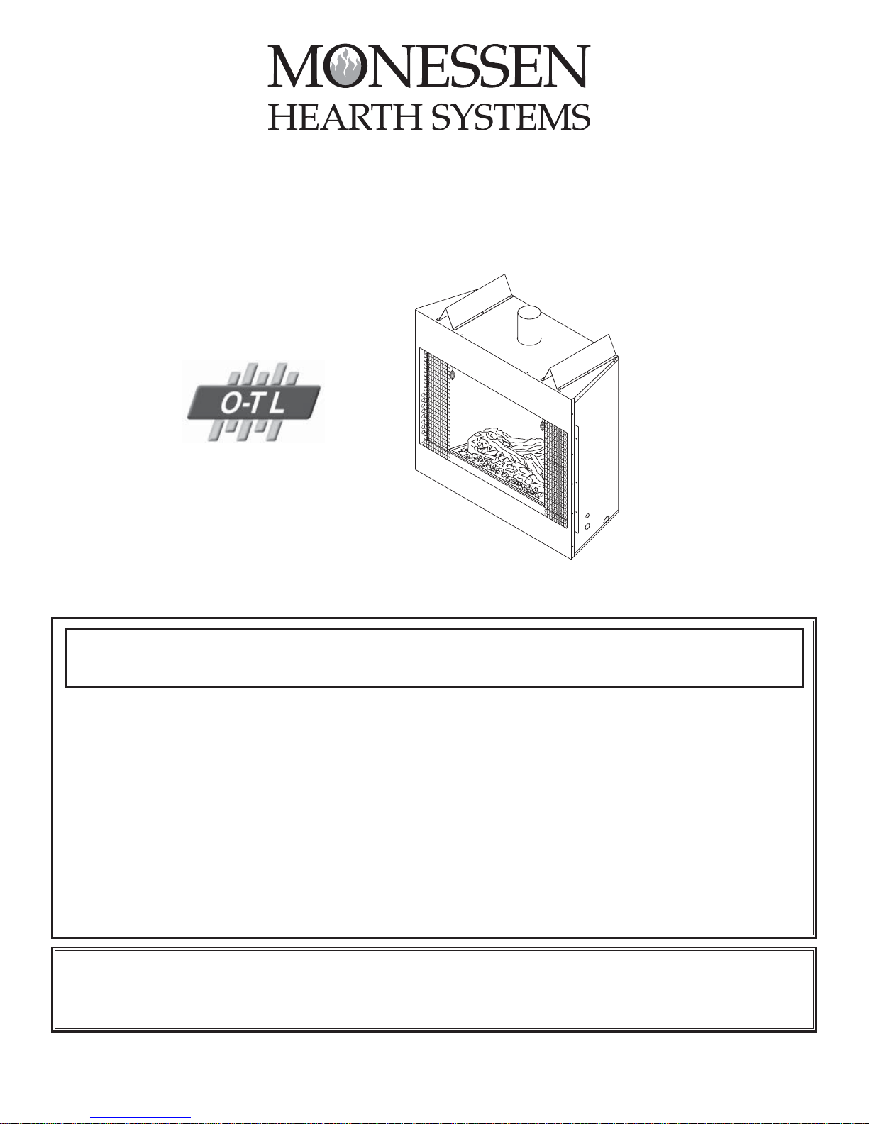
BBV400NV/BBV400NE SERIES
B-VENT DECORATIVE GAS APPLIANCE
INSTALLATION, OPERATION AND MAINTENANCE MANUAL
READ THIS MANUAL BEFORE INSTALLING OR OPERATING THIS APPLIANCE. THIS INSTALLATION, OPERATION AND MAINTENANCE
MANUAL
MUST BE LEFT WITH APPLIANCE FOR FUTURE REFERENCE.
WARNING: IF THE INFORMATION IN THIS MANUAL IS NOT FOLLOWED EXACTL Y, A FIRE OR EXPLOSION MAY RESULT
CAUSING
DO NOT STORE OR USE GASOLINE OR OTHER FLAMMABLE VAPORS AND LIQUIDS IN THE VICINITY OF THIS OR ANY OTHER
APPLIANCE
PROPERTY DAMAGE, PERSONAL INJURY OR LOSS OF LIFE.
.
WHA T TO DO IF YOU SMELL GAS
• DO NOT TRY TO LIGHT ANY APPLIANCE.
• DO NOT TOUCH ANY ELECTRICAL SWITCH; DO NOT USE ANY PHONE IN YOUR BUILDING.
• IMMEDIATELY CALL YOUR GAS SUPPLIER FROM A NEIGHBOR’S PHONE. FOLLOW THE GAS SUPPLIER’S
INSTRUCTIONS
• IF YOU CANNOT REACH YOUR GAS SUPPLIER, CALL THE FIRE DEPARTMENT.
INST ALLATION AND SERVICE MUST BE PERFORMED BY A QUALIFIED INST ALLER, SERVICE AGENCY OR THE GAS SUPPLIER.
DANGER: FAILURE TO FOLLOW THESE INSTRUCTIONS CAREFULLY AND WITHOUT ERROR, OR FAILURE TO HEED ANY
ALL WARNINGS IN THESE INSTRUCTIONS CAN RESULT IN AN EXPLOSION, FIRE OR THE PRODUCTION OF CARBON
AND
MONOXIDE
GAS WHICH CAN CAUSE PROPERTY DAMAGE, BODILY INJURY OR DEATH.
.
53D9015. Rev. 1 03/03
Page 2

TABLE OF CONTENTS
CONGRATULA TIONS!
You have chosen the finest B-vent gas fireplace system available. Y our fireplace has been designed for
years of decorative viewing enjoyment. Please take time to read this entire manual before installing or
operating your system.
Important Information .......................................................................................................................2-4
Appliance System Components ................................................................................ ..5
Clearances ........................
Installation Preparation
Fireplace and Venting Installation ..................................................................................................9
Venting Requirements ........... .............................................................................................10
Gas Supply Connections .............................. .................................................................11
Electrical Wiring .....................................................................................................................................11
Electronic Ignition ................................................................................... .....................12
Fireplace Setup ....................................................................................................................................13
Operating Instructions .....................................................................................................................14-15
Maintenance Instructions ................................................................................................................15-16
Outside Combustion Air Precautions and Recommendations .............................................................17
Combustion Air Assembly .....................................................................................................................18
Troubleshooting .....................................................................................................................................19
Repair Parts List...................................................................................................................................20
................. .................................. ............................................6
...................................................................................................7-8
LISTING AND CODE APPROVALS
U.S. and Canada Certification
The BBV400NV Series Gas Appliance has been tested in accordance with the ANSI Z21.501998/CSA M2.22-M98 Standard for Vented Gas Fireplaces and have been LISTED by OMNITest Laboratories, Inc. for installation and operation as described in these Installation and
Operating Instructions. All components are UL, AGA, CGA, or CSA safety certified.
Local Codes
Check with your local building code agency prior to installing this appliance to ensure
compliance with local codes, including the need for permits and follow-up inspections. This
installation must conform with local codes or, in the absence of local codes, in the USA with
the National Fuel Gas Code, ANSI Z223.1-latest edition.
2
53D9015. Rev 1 03/03
Page 3

IMPORTANT INFORMATION
2
"Warning: If not installed, operated and maintained in accordance with the manufacturer’s
instructions, this product could expose you to substances in fuel or from fuel combustion which
can cause death or serious illness and which are known to the state of California to cause cancer,
birth defects or other reproductive harm. Also, operation, installation and servicing of this product
could expose you to airborne particles of glass wool fibers known to the state of California to
cause cancer through inhalation."
The gas fireplace must be installed and serviced by a qualified installer to conform with local codes. In the
absence of local codes, install to the current National Fuel Gas Code, ANSI Z223.1.
The fireplace and its individual shutoff valve must be disconnected from the gas supply piping system during any
pressure testing of that system at test pressures in excess of 1/2 psig.
The fireplace must be isolated from the gas supply piping system by closing its individual manual shutoff valve
during any pressure testing of the gas supply piping system at test pressures equal to or less than 1/2 psig.
Pressures in excess of 1/2 psig will cause damage to the control valve and may cause damage to the shutoff
valve.
Model BBV400NV (Natural Gas):
Maximum Input: 18,000 BTU Per Hour
Minimum Inlet Gas Supply Pressure: 4.5 inches water column
Maximum Inlet Gas Supply Pressure: 7 inches water column
Manifold Pressure Under Flow Conditions: 3.5 inches water column
Notice: This appliance operates with a yellow, smoky flame. When properly adjusted according
to these instructions, small amounts of carbon (soot) will be deposited on the outlet section of
the air terminal and possibly on surrounding structure. If not properly adjusted and operated
according to these instructions, carbon (soot) will accumulate in larger quantities on the air
terminal and surrounding structure and objects.
Do not attempt to operate the burner at an input rate other than that given by the flame adjustment valve.
Illustrations throughout these instructions reflect typical installations and are for design purposes only. Actual
installation may vary slightly due to individual design preferences. However, minimum and maximum clearances
must be maintained at all times. The illustrations and diagrams in these instructions are not drawn to scale.
Any additions, changes or conversions required in order for the appliance to satisfactorily meet the application
needs must be made by a distributor or dealer using factory specified and approved parts.
This product is manufactured to use natural gas. A natural gas unit can be converted to use propane, but ONLY
if converted by a qualified service technician and ONLY if the Natural Gas to Propane Gas Conversion Kit is
used.
If any assistance is required during installation, please contact your local dealer or the Customer Service
Department.
For Massachusetts Residences Only:
• This product must be installed by a licensed plumber or gas fitter when installed within the
Commonwealth of Massachusetts. Flexline installation must not exceed 36 inches.
3
53D9015. Rev 1 03/03
Page 4

IMPORTANT INFORMATION
This fireplace is a decorative gas appliance.
Do not burn wood or other materials in this fireplace.
Adults and especially young children should be alerted to the hazards of high temperatures and should stay away
to avoid burns or clothing ignition.
Supervise young children when they are in the same room as the fireplace.
Due to high temperatures, the fireplace should be located out of traffic and away from furniture and draperies.
Clothing or other flammable material should not be placed on or near the fireplace.
The fireplace glass door must be in place when the appliance is operating.
Any safety screen or guard removed for servicing the appliance must be replaced prior to operating the fireplace.
It is imperative that the control compartments, burners and circulating air passageways of the fireplace and
venting system are kept clean.
The fireplace and its venting system should be inspected before use and at least annually by a qualified service
person.
5
More frequent cleaning may be required due to excessive lint from carpeting, bedding material, etc.
The fireplace area must be kept clear and free from combustible materials, gasoline and other flammable vapors
and liquids.
This fireplace must not be connected to a chimney flue servicing a separate solid fuel burning appliance.
Under no circumstances should the fireplace be modified.
The fireplace is not intended for use with a thermostat.
Do not use this appliance if any part has been under water.
Immediately call a qualified service technician to inspect the appliance and to replace any part of the control
system which has been under water.
This appliance must be installed with the draft hood in the same atmospheric pressure zone as the combustion air
inlet to the appliance.
4
53D9015. Rev 1 03/03
Page 5
APPLIANCE SYSTEM COMPONENTS
GD36B
GD36PB
OAC4 OUTSIDE
AIR ASSEMBLY
A list of the components that may safely be used with this appliance are listed below.
6
MODELS
BBV400NV Standing Pilot, Natural Gas
BBV400NE Electronic Ignition, Natural Gas
†
Field convertible to propane gas.
Must be installed with one of the glass doors shown below.
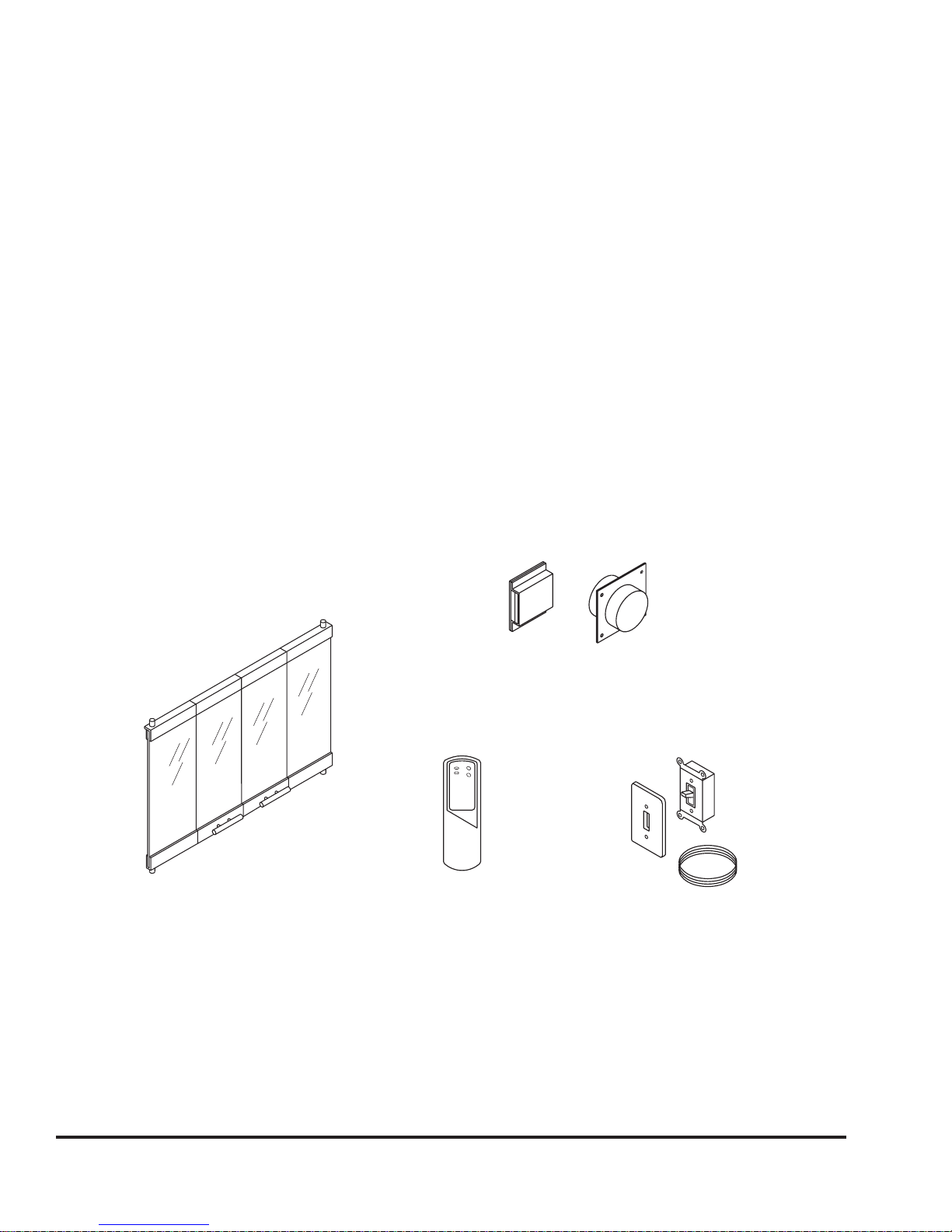
GLASS DOORS
GD36PB Polished Brass Glass Door
GD36B Black Finish Glass Door
††
OPTIONAL
Shown below.
ACCESSORIES
CK35E LP Conversion Kit for Electronic Ignition Model
CK35L LP Conversion Kit for Standing Pilot Model
RC2 Hand Held Remote Control
GFWS Wall Switch
OAC4 Outside Air Kit
†
†
††
††
OAC4 OUTSIDE
AIR ASSEMBLY
GD36B
GD36PB
RC2
HAND HELD REMOTE
CONTROL
GFWS
REMOTE WALL SWITCH
This gas appliance has been tested and listed for use with the optional components listed on this page. Many
optional components may be purchased separately and installed at a later date. However, installation of a blower
kit will require electrical power. T o avoid costly reconstruction, electrical power should be connected to the appliance
at the time of initial appliance installation for possible addition of these accessories at a later date.
5
53D9015. Rev 1 03/03
Page 6

CLEARANCES TO COMBUSTIBLE MATERIALS
GAS LINE
KNOCKOUT
JUNCTION BOX
KNOCKOUT
TOP VIEW
FRONT VIEW
SIDE VIEW
15 1/2" MIN.
FRAMING DIM.
1 7/8"
3 1/2"
6 1/8"
5 1/2"
38"
36"
39" MIN.
FRAMING DIM.
MIN.
FRAMING
DIM.
Sides: 1/2 inch Back: 1/2 inch Bottom: 0 inch
Top: 0 to Top of Spacers Front: 24 inches Ceiling: 48 inches
Vent Pipe: As specified by vent manufacturer.
Notice: Spacers are provided on the top of the unit which allow the fireplace to be listed as a "0" clearance
appliance. A ˚" clearance to combustibles must be maintained from the flat surfaces of the sides and back of the
appliance.
When the fireplace is installed directly on carpeting, vinyl tile or other combustible material other than wood
flooring, the fireplace shall be installed on a metal or wood panel extending the full width and depth of the appliance.
Adequate combustion and ventilation air must be provided. Provide adequate accessibility clearance for servicing
and operating the fireplace. Never obstruct the front opening of the fireplace.
F
IGURE 1
36 1/2"
MIN.
FRAMING
DIM.
FRAMING DIM.
FRONT VIEW
TOP VIEW
36"
38"
39" MIN.
7 13/16"
15"
36 1/2"
33"19 5/8"
15 1/2" MIN.
FRAMING DIM.
6 1/8"
3 1/2"
5 1/2"
4 1/8"
1 7/8"
SIDE VIEW
GAS LINE
KNOCKOUT
JUNCTION BOX
KNOCKOUT
6
53D9015. Rev 1 03/03
Page 7

INSTALLATION PREPARATION
This gas fireplace and its components are tested and safe when installed in accordance with this installation
manual. Report your dealer any parts damaged in shipment, particularly the condition of the glass. Do not install
any unit with damaged, incomplete, or substitute parts.
Read all of the instructions before starting the installation. Follow these instructions carefully during the
installation to ensure maximum safety and benefit. Failure to follow these instructions will void the owner’s
warranty and may present a fire hazard.
When planning a fireplace installation, it is necessary to determine:
• Where the unit is to be installed.
• The vent system configuration to be used.
• Gas supply piping requirements.
• Electrical wiring requirements.
• Framing and finishing details.
• Whether optional accessories - devices such as a fan, wall switch, or remote control - are desired.
HIGH ALTITUDE INSTALLATION
For U.S. installation, units are tested and approved for elevations from 0-2000 feet. When installing this unit at an
elevation above 2000 feet, United States codes require a decrease of the input rating by changing the existing
burner orifice to a smaller size. Input should be reduced 4% for each 1000 feet above sea level. Check with the
local gas utility for proper orifice size identification. Consult your local gas company for assistance in determining
the proper orifice for your locality or refer to ANSI Z223.1-the latest edition, Appendix F.
This appliance has been converted for use at an altitude of
Orifice Size Manifold Pressure
Input (Btu/hr) Fuel T ype
Date of Conversion Converted By
7
53D9015. Rev 1 03/03
Page 8
INSTALLATION PREPARATION
61 3/4"
35 1/4"
1/2" MIN. (13 MM)
30 13/16"
15 1/2"
1" MIN. (25 MM)
39"
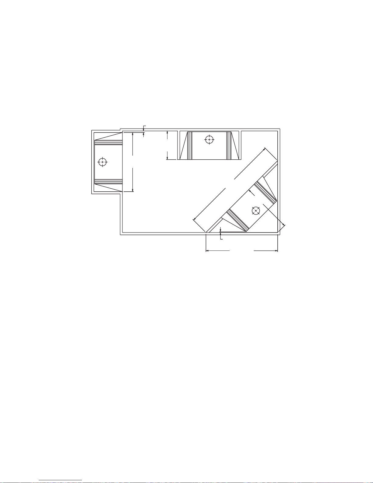
APPLIANCE LOCATIONS AND SPACE REQUIREMENTS
This appliance may be installed along a wall, across a corner or use an exterior chase. The BBV400NV Series
may be installed directly on the floor or on a raised platform to enhance its visual impact. Figure 2 illustrates a
variety of ways the appliance may be located in a room.
Due to high temperatures, the appliance should be located out of traffic and away from furniture and draperies.
1" MIN. (25 MM)
F
IGURE 2
15 1/2"
39"
61 3/4"
30 13/16"
1/2" MIN. (13 MM)
35 1/4"
FRAMING THE ENCLOSURE
Figure 3 shows a typical framing of this appliance assuming combustible materials are used. All required clearances
shown in Figures 1 and 3 to combustibles around the appliance must be adhered to. Any framing at the back and
sides of the appliance must be outside the spacers. Any framing on top of the appliance must be above the top
spacers.
Fireplace framing can be built before or after the fireplace is set in place. Framing should be positioned to
accommodate wall coverings and fireplace facing material.
8
53D9015. Rev 1 03/03
Page 9

12"
MAX.
3 1/2" MIN.
NON-COMBUSTIBLE
MATERIAL
12" MIN. FROM
FIREPLACE OPENING
TO BOTTOM OF
COMBUSTIBLE
MANTEL
2"MIN.
STORM COLLAR
FLASHING
APPROVED COWL
6 FT.
MIN.
AS SPECIFIED BY VENT
MANUFACTURER.
"B" VENT CLEARANCE
MINIMUM CLEARANCE AS
MANUFACTURER.
SPECIFIED BY VENT
SUPPORT
LISTED CEILING
GAS VENT
4" TYPE "B"
WALL
1/2" AIR SPACE TO SIDES
AND REAR OF FIREPLACE.
GAS APPLIANCE
FLOOR
FIREPLACE AND VENTING INSTALLATION
COWL
CHIMNEY
FIGURE 3
APPROVED COWL
STORM COLLAR
FLASHING
4" TYPE "B"
GAS VENT
6 FT.
MIN.
LISTED CEILING
SUPPORT
12" MIN. FROM
FIREPLACE OPENING
TO BOTTOM OF
COMBUSTIBLE
MANTEL
3 1/2" MIN.
NON-COMBUSTIBLE
MATERIAL
12"
MAX.
FLOOR
MINIMUM CLEARANCE AS
SPECIFIED BY VENT
MANUFACTURER.
"B" VENT CLEARANCE
AS SPECIFIED BY VENT
2"MIN.
MANUFACTURER.
1/2" AIR SPACE TO SIDES
AND REAR OF FIREPLACE.
WALL
GAS APPLIANCE
APPROVED
COWL
AS SPECIFIED
BY VENT
MANUFACTURER.
APPROVED THIMBLE FOR
4" TYPE "B" GAS VENT
THROUGH WALL
12" MIN. FROM
FIREPLACE OPENING
TO BOTTOM OF
COMBUSTIBLE
MANTEL
3 1/2" MIN.
NON-COMBUSTIBLE
MATERIAL
FLOOR
12"
MAX.
2" MIN.
SUPPORT
4" TYPE "B" GAS VENT
CHIMNEY
WALL
1/2" AIR SPACE TO SIDES
AND REAR OF FIREPLACE.
GAS APPLIANCE
53D9015. Rev 1 03/03
1 FT.
MIN.
"0" CLEARANCE TO SPACERS
9
Page 10

VENTING REQUIREMENTS
Warning: Do not connect this appliance to a chimney flue serving a separate solid fuel burning appliance.
Carbon deposits (Soot) and creosote from solid fuels can clog the vent from the appliance causing
poisonous carbon monoxide to be released into the room in which the appliance is installed.
All vented gas-fired appliances when operating correctly produce small concentrations of carbon monoxide along
with other combustion products. Should something interfere with the operation of the appliance, it is possible for
the appliance to produce deadly quantities of poisonous carbon monoxide. All flue products from this appliance
must be vented to the outside at all times. Never operate an appliance designed to be vented without a correctly
working vent system connected to the appliance.
Warning: V enting of this appliance is one of the most important parts of the installation. V enting systems
must be installed and inspected according to these instructions and local codes or in the absence of local
codes, according to the National Fuel Gas Code Z223.1 - Latest edition, by a licensed or otherwise qualifed
installer.
Your local gas company should have copies of the National Fuel Code Z223.1 or other installation codes applicable
to your area.
Venting requirements and accepted methods vary greatly depending on the particular installation. It is impossible
to thoroughly define all possible installation circumstances in this manual. The following instructions and illustrations
are general guidelines only . All venting material must be instatlled according to local codes, or in the absence of
such codes, according to the National Fuel Gas Code Z223.1.
Warning: An improperly vented gas-fired appliance can lead to death from carbon monoxide posioning.
Venting materials are not provided with this appliance and must be purchased separately.
This appliance must be installed using 4" type “B” vent that has been listed by a nationally recognized testing
agency..
Attach the vent pipe to the appliance using four (4) sheet metal screws.
Vent must maintain minimum rise of ˘ inch per foot of horizontal run.
Venting terminals shall not be recessed into a wall or siding.
10
53D9015. Rev 1 03/03
Page 11

GAS SUPPLY CONNECTIONS
Both rigid and flexible gas lines are approved for use with these appliances. Consult you local codes for approved
gas piping practices. Some local codes may require the installation of a manual main shut-off valve and union
external to the appliance. Approved components must be used and the union must be of the ground joint type.
1. Knockouts are on each side of the fireplace outer jacket for convenience in running the gas line to the unit.
2. Choose the gas line routing that results in the shortest length of run and requires the least number of fittings
and joints to avoid excessive pressure drop.
3. Connect the gas line to the inlet side of the gas valve.
NOTE: Compounds used on thread joints of gas piping must be resistant to the actions of liquefied
petroleum gases.
A 1/8 inch (3 mm) N.P.T. plugged tapping, accessible for test gauge connection, should be provided in the
gas supply line leading to the unit’s shutoff valve.
4. After gas piping installation is complete, carefully check all piping connections for gas leaks using a leak
detecting solution.
Caution: The gas valve can be damaged if subjected to more than ˚ psig during pressure testing
of the gas piping system. The gas valve must be disconnected or isolated from the piping system
during pressure testing.
ELECTRICAL WIRING
NOTE: This appliance must be electrically wired and grounded in accordance with local codes
and/or with the National Electric Code ANSI/NFPA 70 - Latest Edition, and Canadian Electrical
Code C22.1.
1. Model BBV400NV uses a millivolt standing pilot valve system and does not require a 110 volt supply for
operation.
Warning: Do not connect 110 Vac to millivolt valve. This will cause the unit to malfunction and
destroy the valve control system.
11
53D9015. Rev 1 03/03
Page 12

ELECTRONIC IGNITION
TAP
LIMIT SWITCH
WALL
GAS CONTROL/ELECTRONIC IGNITION ROUTING
PILOT
TO BURNER
GAS LINE-OUT
EQUIVALENT.
WITH SAME OR
DEGREE C. REPLACE
WIRE TYPE 105
SUPPLY
PILOT GAS
GROUND
PILOT BURNER
GND
COMMON
LINE
120V. 60 Hz.
POWER SUPPLY
TRANSFORMER
SWITCH
IGNITION WIRE
TAP
PRESSURE
OUTLET
ELECTRONIC CONTROL
CONTROL ADJUST. SCREW
INLET PRESSURE
IN
GAS CONTROL VALVE
GAS SUPPLY - IN
ON
OFF
MV
PV
PV
MV
SPARK
(OPT)
TH-W
24V
(GND)
24V
(BURNER)
GND
PV
MV/PV
MV
WARNING
PV-1A MAX. MV-1A MAX.
24V, 60 Hz
90 SEC. L.O.
100% SHUTOFF IP
S8600H
device that has been wet - replace it.
it gets wet. Never try to use a
This device can malfunction if
serious injury or death.
Explosion hazard. Can cause
3. Model BBV400NE requires connection to a 110 VAC supply from a remote wall switch to the Junction Box.
Connect the 110 VAC supply to the transformer leads and the receptacle. Insure that the 110 VAC supply is
properly grounded to the unit. Figure 4.
Caution!: Always make sure the power is "OFF" before attempting to install or service any electrical
wiring or components.
FIGURE 4
GAS CONTROL/ELECTRONIC IGNITION ROUTING
PILOT
DEGREE C. REPLACE
WIRE TYPE 105
WITH SAME OR
EQUIVALENT.
GAS LINE-OUT
TO BURNER
PILOT BURNER
GROUND
GAS CONTROL VALVE
GAS SUPPLY - IN
IN
CONTROL ADJUST. SCREW
OUTLET
PRESSURE
TAP
PILOT GAS
SUPPLY
MV
MV
OFF
ON
PV
PV
ELECTRONIC CONTROL
S8600H
100% SHUTOFF IP
90 SEC. L.O.
24V, 60 Hz
PV-1A MAX. MV-1A MAX.
PV
(GND)
24V
24V
GND
(BURNER)
7
6
5
4
IGNITION WIRE
WARNING
Explosion hazard. Can cause
serious injury or death.
This device can malfunction if
it gets wet. Never try to use a
device that has been wet - replace it.
MV
MV/PV
3
21
INLET PRESSURE
TAP
(OPT)
TH-W
8
LIMIT SWITCH
POWER SUPPLY
SPARK
9
WALL
SWITCH
TRANSFORMER
120V. 60 Hz.
LINE
COMMON
GND
12
53D9015. Rev 1 03/03
Page 13

FIREPLACE SETUP
1. Remove the box containing the log from the firebox and discard the two (2) shipping pads. Carefully remove
the log from the box.
2. Position log over burner as shown in Figure 5. Wear protective gloves to place glowing ember meterial in front
and on top of burner tube. The ember material should be separated into small (nickel size) pieces and spread
evenly in front of burner. Lava rock may be placed on the hearth around the ember material.
Warning: Improper log placement may result in production of increased quanities of poisonous
carbon monoxide and soot.
3. Install the glass door assembly supplied separately from this package. The glass door is installed by inserting
the top two (2) pins into the receiving holes above the fireplace opening and then inserting two (2) pins into the
bottom. Use care not to bump or scratch the glass. Glass door assembly model number GD36PB or model
number GD36B must be installed when the fireplace is in use.
IGURE 5
F
BURNER TUBE
EMBER MATERIAL
LAVA ROCK
DO NOT COVER
LARGE PORT HOLES
13
53D9015. Rev 1 03/03
Page 14

GAS VALVE SHOWN IN PILOT POSITION
CONTROL
KNOB
PILOT ADJUSTMENT
SCREW
SUPPLY
GAUGE PORT
MANIFOLD
GAUGE PORT
HI/LO FLAME
ADJUSTMENT KNOB
TP
TH
TP
TH
OPERATING INSTRUCTIONS
A. BEFORE LIGHTING smell all around the appliance area for gas. Be sure to smell
next
to the floor because some gas is heavier than air, and will settle on the f
loor.
WHAT TO DO IF YOU SMELL GAS
Do not try to light any appliance.
Do not touch any electrical switch; do not use any phone in your buil
ding.
Immediately call your gas supplier from a neighbor's phone. Follow th
e supplier's
instructions.
If you cannot reach your gas supplier, cal
l the fire department.
B. Use only your hand to push in or turn knob. Never use tools. If the knob will
not push
in or turn by hand, don't try to repair it; call a qualified service techni
cian Forced or
attempted repair may result in a fire or explosion.
C. Do not use this appliance if any part has been under water. Immediately call aa
qualified service technician to inspect the appliance and to replace any pa
rt of the
control system and any gas control which has been under water.
WARNING!
IF YOU DO NOT FOLLOW THESE INSTRUCTIONS EXACTLY, A FIRE OR
EXPLOSION MAY RESULT CAUSING PROPERTY DAMAGE, PERSONAL
INJURY OR LOSE IF LIFE.
FOR YOUR SAFTEY READ BEFORE LIGHTING
Warning!: Never operate this unit with the glass removed.
FOR YOUR SAFTEY READ BEFORE LIGHTING
WARNING!
IF YOU DO NOT FOLLOW THESE INSTRUCTIONS EXACTLY, A FIRE OR
EXPLOSION MAY RESULT CAUSING PROPERTY DAMAGE, PERSONAL
INJURY OR LOSE IF LIFE.
A. BEFORE LIGHTING smell all around the appliance area for gas. Be sure to smell
to the floor because some gas is heavier than air, and will settle on the f
loor.
next
WHAT TO DO IF YOU SMELL GAS
Do not try to light any appliance.
Do not touch any electrical switch; do not use any phone in your buil
Immediately call your gas supplier from a neighbor's phone. Follow th
ding.
e supplier's
instructions.
If you cannot reach your gas supplier, cal
B. Use only your hand to push in or turn knob. Never use tools. If the knob will
in or turn by hand, don't try to repair it; call a qualified service techni
l the fire department.
not push
cian Forced or
attempted repair may result in a fire or explosion.
C. Do not use this appliance if any part has been under water. Immediately call
qualified service technician to inspect the appliance and to replace any pa
rt of the
control system and any gas control which has been under water.
MILLIVOLT STANDING PILOT SYSTEM
1. If an optional wall mounted switch or appliance mounted On/Off switch was used, switch to the “OFF” position.
2. Turn off all electrical power to the appliance.
3. Open the hinged lower grille. Push in gas control knob slightly and turn clockwise to “OFF”.
4. Wait five (5) minutes to clear out any gas. If you then smell gas do not attempt to light. Follow the instructions
in the warning above. If you do not smell gas proceed to the next step.
5. Depress gas valve control knob partially, and turn counterclockwise to the pilot position. Figure 6.
6. Depress control knob in until it stops and hold
in this position while pushing the red piezo
ignitor button until the pilot lights. The control
knob should be held depressed for a few
seconds. Release the control knob and the
pilot should remain lit.
7. Depress the control knob partially and turn
counterclockwise to the "ON" position.
8. If an optional wall switch or appliance mounted
switch was used, switch to "ON". The main
burner should now be "ON".
9. Close the lower grille.
14
53D9015. Rev 1 03/03
F
IGURE 6
ADJUSTMENT KNOB
TP
TH
TP
TH
PILOT ADJUSTMENT
HI/LO FLAME
SCREW
GAS VALVE SHOWN IN PILOT POSITION
MANIFOLD
GAUGE PORT
L
O
I
H
O
F
F
O
N
CONTROL
KNOB
SUPPLY
GAUGE PORT
P
I
L
O
T
Page 15

OPERATING INSTRUCTIONS
TO TURN OFF GAS TO APPLIANCE
1. TURN GAS CONTROL KNOB
CLOCKWISE TO OFF.
2. TURN OFF ALL ELECTRICAL
POWER TO THE UNIT.
3. SHUT OFF MAIN GAS SUPPLY
VALVE TO THE UNIT.
GAS CONTROL
KNOB
POSITION
INDICATER
ON
OFF
ELECTRONIC IGNITION SYSTEM
1. STOP! Read the safety information at the beginning of this section.
2. Turn off the electric power to the appliance.
3. This appliance is equipped with an ignition device which automatically lights the pilot. Do
NOT try to light the
pilot by hand.
4. Open control access panel.
5. Turn gas control knob clockwise to "OFF". Refer to Figure 7.
F
IGURE 7
POSITION
INDICATER
ON
OFF
GAS CONTROL
KNOB
TO TURN OFF GAS TO APPLIANCE
1. TURN GAS CONTROL KNOB
CLOCKWISE TO OFF.
2. TURN OFF ALL ELECTRICAL
POWER TO THE UNIT.
3. SHUT OFF MAIN GAS SUPPLY
VALVE TO THE UNIT.
6. Wait five (5) minutes to clear out any gas. If you then smell gas, STOP! Follow the instructions in the warning
on page 14. If you do not smell gas, go to next step.
7. Turn gas control knob counterclockwise to "ON".
8. Close control access panel.
9. Turn on all electric power to the appliance.
10. If the appliance will not operate, follow the instructions "To Turn Of f Gas To Appliance" and call your service
technician or gas supplier.
MAINTENANCE INSTRUCTIONS
1. Control Compartment - Keep the control compartment clean by brushing and vacuuming at least once a year.
Always turn off the gas valve and all electrical power to the unit before cleaning.
2. Checking Flame Patterns - The burner flame pattern should be checked periodically. The flames should be
steady and not lifting. See Figure 8.
3. Vent System Inspection - The appliance and vent system should be inspected at least annually. A qualified
service person should check vent pipe and all connections for tightness and to make sure there is no blockage
at the termination, no unusual corrosion or other damage.
4. The appliance area must be kept clear and free from combustible materials, gasoline and other flammable
vapors and liquids.
15
53D9015. Rev 1 03/03
Page 16

RED GLOWING EMBERS
1. LOOK DOWN BETWWEN THE LOGS TO SEE THE BURNER.
THE FLAMES SHOULD BE STABLE ON THE BURNER.
2. THE FLAMES SHOULD BE BLUE AT THE BURNER AND
YELLOW AT THE TOP.
3. INSURE THAT THE PILOT FLAME IS STABLE AND
CONTACTING THE THERMOPILE.
YELLOW TIPPED FLAMES
LOW MASS
THERMOCOUPLE
THERMOCOUPLE
PILOT
MAINTENANCE INSTRUCTIONS
YELLOW TIPPED FLAMES
FIGURE 8
1. LOOK DOWN BETWWEN THE LOGS TO SEE THE BURNER.
THE FLAMES SHOULD BE STABLE ON THE BURNER.
2. THE FLAMES SHOULD BE BLUE AT THE BURNER AND
YELLOW AT THE TOP.
3. INSURE THAT THE PILOT FLAME IS STABLE AND
CONTACTING THE THERMOPILE.
RED GLOWING EMBERS
THERMOCOUPLE
PILOT
LOW MASS
THERMOCOUPLE
5. Insure that the flow of combustion and ventilation air is not obstructed.
6. Do not use this appliance if any part has been under water. Immediately call a qualified service technician to
inspect the appliance and to replace any part of the control system and any gas control which has been under
water.
7. This appliance must only be operated with glass door model number GD36PB or model number GD36B
properly installed per the Fireplace Setup instruction section of this manual. If the door is damaged or broken,
it may only be replaced by a complete assembly as supplied by the manufacturer. See the Repair Parts List.
8. Never attempt to replace the glass panel with another piece of glass or use any other substitute materials.
9. Never attempt to operate this appliance with a broken glass door.
10. When removing or replacing the glass door for cleaning or inspection, care must be taken not to abuse the
glass panel by striking, slamming shut, or scratching against other surfaces.
11. Only trim kits and other optional accessories supplied by the manufacturer may be used with this appliance.
Draft relief openings must never be covered or blocked.
12. Cleaning the glass - Wear gloves while handling the glass door assembly. DO NOT REMOVE GLASS DOOR
WHEN HOT. Handle the glass door with care to avoid striking or scratching the glass. Clean the inside and
outside surfaces of the glass panel using a mild detergent and water solution with a soft cloth. Do
abrasive cleansers which might scratch the glass surface. Do not attempt to clean the glass when the surface
is hot. The glass door must be properly reinstalled after cleaning. Do not operate this appliance without the
glass door properly in place.
13. Service - Any service to the burner/gas control system or electrical system and its components, must only be
performed by a qualified service technician.
16
53D9015. Rev 1 03/03
not use
Page 17

OUTSIDE COMBUSTION AIR PRECAUTIONS & RECOMMENDATIONS
CONCRETE SLAB INSTALLATION
(OPTIONAL OUTSIDE AIR RUNS)
INLET GRILLE
IN SOFFIT
(OVERHANG)
8' MAX.
TO OUTSIDE WALL
DUCT EXTENDED
TO MISS JOIST
NOTE: The use of outside air for combustion is optional unless required by building codes. It is only necessary
to supply outside combustion air to one side of the fireplace. Use the model OAC4 combustion air kit.
1. Extremely long runs and numerous turns in the duct leading from the fireplace to the combustion air assembly
should be avoided. These conditions will increase the resistance to the free flow of air through the duct.
Refer to Figure 9 for methods of installing the outside air for combustion assemblies.
2. The combustion air assembly should be located at an exterior location, which is not likely to be accidentally
blocked in any manner. The assembly should be located above the snow line to prevent blockage by snow
accumulation.
3. The combustion air inlet assembly should never be mounted in a garage or storage area where combustible
fumes such as gasoline might be drawn into the fireplace.
4. Combustion air can be drawn from the crawl space under a house when an adequate supply of air is
provided by open ventilation.
5. Do not take combustion air from attic space or garage space.
DUCT EXTENDED
TO MISS JOIST
TO OUTSIDE WALL
INSTALLATION ABOVE BASEMENT
OR CRAWL SPACE
FIGURE 9
INLET GRILLE
8' MAX.
IN SOFFIT
(OVERHANG)
CONCRETE SLAB INSTALLATION
(OPTIONAL OUTSIDE AIR RUNS)
17
53D9015. Rev 1 03/03
Page 18

LONGER LENGTH OF THE TUBE
TO OUTSIDE.
INSERT SHORTEST SIDE OF
THE TUBE THROUGH THE
FIREPLACE OUTER WRAP.
STEP 1: SECURE OUTSIDE AIR STARTING
COLLAR TO LEFT SIDE OF FIREPLACE WITH
FOUR SHEET METAL SCREWS PROVIDED.
STEP 2: SECURE OUTSIDE
DUCT TO STARTING COLLAR
WITH DUCT CLAMP OR SCREWS.
SCREWS
6" DIA. HOLE FOR OAC4
NAIL
HOLES
COMBUSTION AIR ASSEMBLY
MODEL OAC-4 COMBUSTION AIR ASSEMBLY
1. Remove the cover plate from the 4-inch outlet opening location on the left outside of the fireplace. DO NOT
remove the cover if the outside air will not be connected.
2. Place the starting collar (4 inch) into the hole on the left side of the fireplace. Fasten it in place with the four
sheet metal screws provided.
3. Cut a 6-inch diameter opening for model OAC-4 in the outside wall covering where the outside vent is to be
located.
4. Select and cut a piece of duct sufficient length to attach to the fireplace and protrude at least three inches
beyond the face of the wall to which the inlet air vent will be attached. The duct may be cut with a standard
pocket knife (use FP-4 U duct for maximum efficiency and safety). Do not use a combustible duct. Always
use UL Listed Class 0 or 1 duct material. If it is necessary to splice the duct, a Model 403 duct connector
should be used to splice duct sections.
5. If the duct is the insulated type, push the insulation back from one end of the duct approximately two
inches.
6. Slip the exposed end of the duct over the starting collar on the fireplace.
7. Using the sheet metal screws or duct clamps, secure the duct to the starting collar and to the outside vent.
8. Nail or screw the outside vent to the surface of the wall.
FIGURE 10
SCREWS
INSERT SHORTEST SIDE OF
THE TUBE THROUGH THE
FIREPLACE OUTER WRAP.
6" DIA. HOLE FOR OAC4
NAIL
HOLES
STEP 1: SECURE OUTSIDE AIR STARTING
COLLAR TO LEFT SIDE OF FIREPLACE WITH
FOUR SHEET METAL SCREWS PROVIDED.
18
53D9015. Rev 1 03/03
LONGER LENGTH OF THE TUBE
TO OUTSIDE.
STEP 2: SECURE OUTSIDE
DUCT TO STARTING COLLAR
WITH DUCT CLAMP OR SCREWS.
Page 19

TROUBLESHOOTING
While the manufacturer has made every reasonable effort to insure that this heater operates properly and
satisfactorily , sometimes problems do arise. The following troubleshooting chart lists several problems with their
probable cause and solution. Any adjustments and/or replacements must be made by a qualified person. Do not
replace any component with a different type. Only use components supplied by the manufacturer of this heater .
Problem
Flame too large.
Noisy flame.
Yellow excessive flame.
Floating flame.
Delayed ignition.
Cause
Pressure regulator set too high.
Defective regulator on heater.
Burner orifice too large. Replace with correct size.
Noisy pilot.
Burr in orifice.
Too little primary air.
Clogged burner ports.
Misaligned orifice.
Clogged vent system
Blocked venting.
Insufficient primary air .
Improper pilot location.
Pilot flame too small.
Burner ports clogged. Clean ports.
Solution
Reset, using manometer.
Replace.
Reduce pilot gas.
Remove burr or replace.
Clean air intake to burners..
Clean ports.
Realign or replace burner .
Clean.
Clean.
Clean intake to burners.
Reposition pilot.
Check orifice, increase gas.
Failure to ignite.
Main burner won’t turn OFF .
Main burner won’t turn ON.
Burner and pilot flame go
out.
Low pressure. Adjust pressure regulator.
Main gas OFF . Open manual valve.
Defect in gas valve.
Defective auto. pilot valve.
Defective auto. valve.
Defective auto. valve.
Defective thermocouple.
Defective switch.
Poorly functioning vent system
Gas supply interrupted.
Defective thermocouple or control
Replace.
Clean or replace.
Replace.
Replace.
Repair or replace.
Replace.
If pilot can be relit but main burner and pilot go
off after ignition, have vent system checked and
corrected immediately .
Attempt to relight pilot and main burner. If unable
to relight pilot, check thermocouple and/or control.
Replace.
19
53D9015. Rev 1 03/03
Page 20

PARTS LIST
Part
077155A
077154A
077101A
073728A
066308A
077403A
073390A
073391A
057958A
057955A
057956A
060874A
053297A
053298A
Description
All repair part orders should be placed through your local dealer. To ensure prompt and accurate service, please
provide the following information when placing a repair part order: Model number of your Appliance, Part Name,
Part Number, and Quantity of parts needed.
Technical Service Department
2813 W. Mall Drive, Unit B.
Florence, Alabama 35630.
Tel. - 1-866-500-5671
www.monessenhearth.com
Description
Glass Door Brass
Glass Door Black
Log Set
Burner
Orifice (Natural #45)
Orfice (LP #55)
Pilot (Standing Piiot Natural)
Pilot (Standing Pilot LP)
Piezo Ignitor
Gas Valve (Standing Pilot Natural)
Gas Valve (Standing Pilot LP)
Pilot (Electronic Ignitor)
Gas Valve (Electronic Ignitor)
Transformer Assembly
Electronic Ignitor Module
Part
077155A
077154A
077101A
073728A
066308A
077403A
073390A
073391A
057958A
057955A
057956A
060874A
053297A
053298A
052139A
20
53D9015. Rev 1 03/03
Page 21

NOTES
21
53D9015. Rev 1 03/03
Page 22

NOTES
22
53D9015. Rev 1 03/03
Page 23

NOTES
23
53D9015. Rev 1 03/03
Page 24

ATTENTION
APPLIANCE
INSTALLER
PLEASE RETURN THESE OPERATING
AND
INSTALLATION INSTRUCTIONS
TO THE APPLIANCE FOR
53D9015. REV 1 03/03
CONSUMER USE.
 Loading...