

Page 1
Stainless Steel Outdoor Kit Installation Instructions
Model: AVFLSTSSODK
This stainless steel outdoor kit is designed to allow
installation of the model AVFLST42 see-through replace
on an exterior wall so the control side is on the interior of
the building, and the opposite side is viewable from outside
the building.
This kit comes pre-assembled and ready to install. It must
be installed on the unit before the replace is secured into
its nal position.
After installation, exterior noncombustible nishing material
such as stone or brick may be placed over the outer
surround of the facing kit only. Do not cover any portion of
the inner glass window frame.
NOTE: Remove four shipping brackets from each corner on
the inside of the face prior to installation.
Kit contents:
• Facing kit assembly .................................................... 1
• Side face caps ............................................................ 2
• Glass door assembly .................................................. 1
• #8 X 1/2" hex head screws ........................................ 12
• #8 X 1/2" ss hw tek screws ........................................... 6
• #8 X 1" ss epoxy coated pan head screws ................... 3
• 24 x 1" Phillips pan head screws ............................... 10
• #10 x 1/2" od fender washer, zinc plated ................... 10
• Installation brackets .................................................... 6
• Instructions .................................................................. 1
Installation Instructions
NOTE: The stainless steel outdoor kit can only be installed
on the side of the replace designed to face the outside of
the building. The interior side of the replace has the control
system accessible through the lower access panel.
1. Remove all loose contents from the AVFLST42 seethrough replace including hardware, packaging
materials, screens and both access panels.
2. Carefully lean unit so the outdoor side is facing up. Use
a helper or lean against a suitable prop.
3. Remove the black face from the non-control side of the
unit held in place by 24 screws (four on the left, four
on the right, four on the bottom, ve on the top, four
on the inner rebox and three on the top of the inner
rebox.) See Figure 2. Both noncombustible brackets
and standoffs must be removed on the non-control side
and may be discarded.
4. Install face caps to left and right sides of replace using
supplied screws. Figure 3.
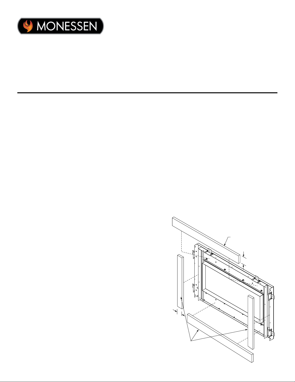
Noncombustible
Insulation
(not supplied)
3¼"
Tools/Supplies required:
• Short handle Phillips head screwdriver
• Long handle Phillips head screwdriver
• Caulk gun & caulk suitable for outside use
NOTE: To improve the thermal insulation properties of
your outdoor kit, we recommend installing four (4) strips of
noncombustible insulation (not supplied) behind the facing
kit inside the perimeter of the outer frame. Before installing
the face, install insulation with a thin coat of construction
adhesive. Figure 1.
2¾"
Noncombustible
Insulation
(not supplied)
Figure 1. Installing recommended insulation
20308722 0616 Rev. 1
Page 2
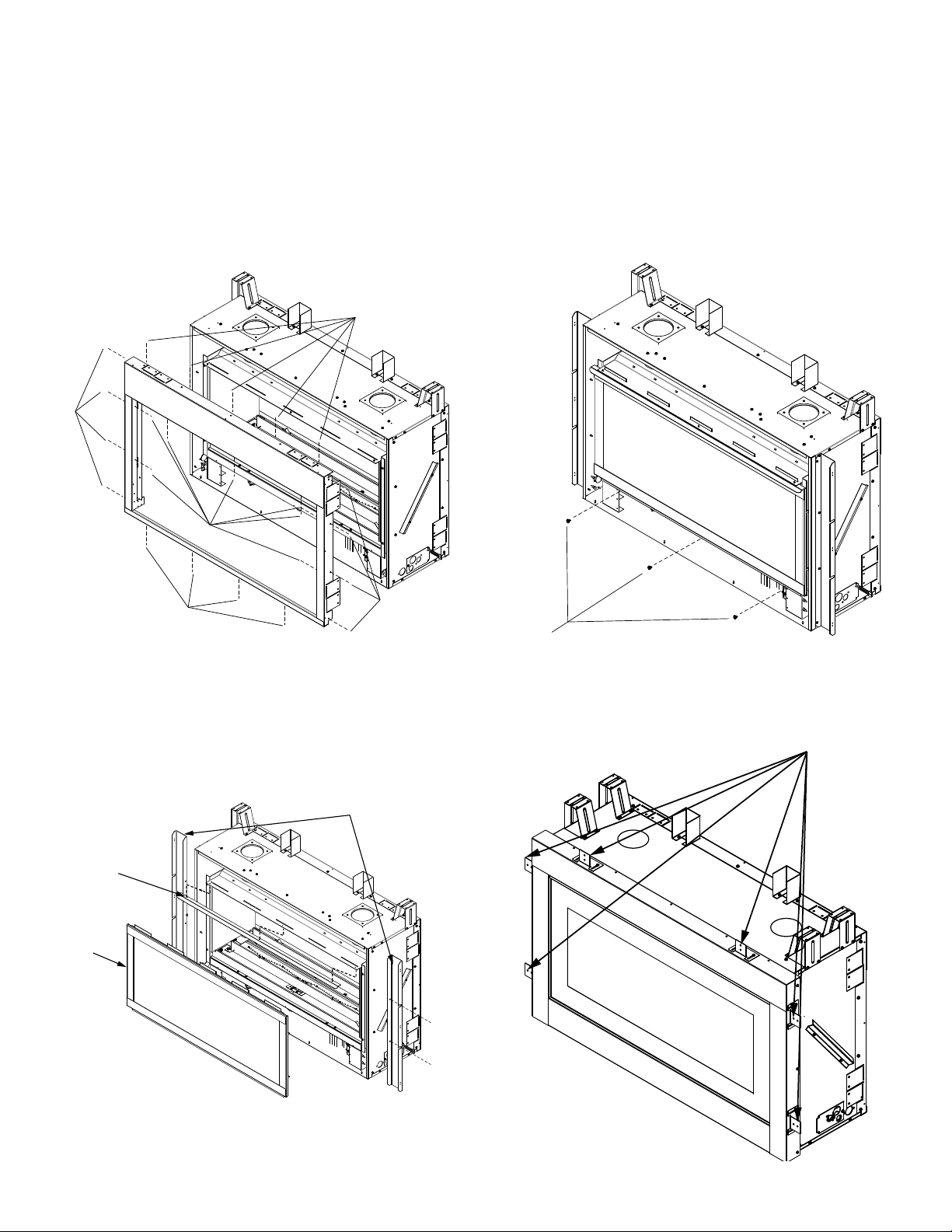
5. Install the glass door seal bracket with the three (3)
Phillips pan head screws that were on the top of the
inner rebox. Figure 3.
NOTE: Before proceeding, ensure the glass on the outdoor
side of the replace is cleaned thoroughly.
6. Install the glass door by aligning the ngers at the top
of the door frame with the slots inside the glass door
seal bracket, and slide into place at an angle. After
ngers are fully engaged, rest the glass door against
the bottom of the rebox to align the three mounting
holes. Use the supplied screws to secure in place. See
Figure 4.
Remove screws
Remove
screws
7. Afx the outdoor kit to the top and sides of the unit using
supplied #8 stainless steel screws.
8. Carefully return replace to upright position.
9. Install installation brackets. Installation brackets can be
positioned to accommodate the thickness of the outer
wall sheathing. Figure 6.
Remove screws
Remove screws
Figure 2. Remove the black face from the unit
Glass door
seal bracket
Glass door
Remove screws
Glass door screws
Figure 4. Glass door and face caps installed
Installation brackets
Face caps
Figure 3. Install glass door and face caps
2
Face cap
Screw installation
Figure 5. Face attached to caps
20308722
Page 3

10. Position replace in nal installation location. Secure
the installation brackets to the wall framing. Install
electrical supply, gas supply and venting according to
installation instructions supplied with your replace.
11. Install facing material, following the parameters in the
gure below. Caulk around facing material to weatherseal facing kit. Figure 7.
Sheathing can go to
zero clearance on
sides of unit.
Figure 6. Installation bracket and sheathing
Noncombustible
facing material must
overlap face by at
least 3/4"
Noncombustible facing
material must not extend
beyond this edge
Adjustable installation
bracket
Noncombustible
facing material must
overlap face by at
least 3/4"
Noncombustible facing
material must not extend
beyond this edge
Noncombustible
facing material must
overlap face by at
least 3/4"
Noncombustible facing
material must not extend
beyond this edge
Figure 7. Facing material installed
20308722
Noncombustible
facing material must
overlap face by at
least 3/4"
Noncombustible facing
material must not extend
beyond this edge
Seal these seams with caulk
3
Page 4

149 Cleveland Drive • Paris, Kentucky 40361
www.monessenhearth.com
4
20308722
 Loading...