

Page 1
1
Monessen • AVFL60 Installation Manual • 4605-901 Rev. A • 05/17
Models:
AVFL60NIP
AVFL60PIP
Installation Manual
Installation and Appliance Setup
INSTALLER: Leave this manual with party responsible for use and operation.
OWNER: Retain this manual for future reference.
NOTICE: DO NOT discard this manual!
In the Commonwealth of Massachusetts
installation must be performed by a licensed
plumber or gas tter.
See Table of Contents for location of
additional Commonwealth of Massachusetts
requirements.
• DO NOT store or use gasoline or other am-
mable vapors and liquids in the vicinity of this
or any other appliance.
• What to do if you smell gas
- DO NOT try to light any appliance.
- DO NOT touch any electrical switch. DO
NOT use any phone in your building.
- Leave the building immediately.
- Immediately call your gas supplier from
a neighbor’s phone. Follow the gas supplier’s instructions.
- If you cannot reach your gas supplier, call
the re department.
• Installation and service must be performed
by a qualied installer, service agency, or the
gas supplier.
WARNING:
FIRE OR EXPLOSION HAZARD
Failure to follow safety warnings exactly
could result in serious injury, death, or
property damage.
ARTISAN
SERIES
This is an unvented gas-red heater. It uses air
(oxygen) from the room in which it is installed.
Provisions for adequate combustion and ventil-
ation air must be provided. Refer to Page 6.
DO NOT install this unit in a bedroom or
bathroom. Please refer to page 6 Section F for
proper unit placement.
Page 2

2
Monessen • AVFL60 Installation Manual • 4605-901 Rev. A • 05/17
Safety Alert Key:
• DANGER! Indicates a hazardous situation which, if not avoided will result in death or serious injury.
• WARNING! Indicates a hazardous situation which, if not avoided could result in death or serious injury.
• CAUTION! Indicates a hazardous situation which, if not avoided, could result in minor or moderate injury.
• NOTICE: Used to address practices not related to personal injury.
Table of Contents
Installation Standard Work Checklist ....................3
1 Product Specic and Important Safety Information
A. Appliance Certication ............................4
B. BTU Specications ...............................4
C. High Altitude Installations ..........................4
D. Non-Combustible Materials Specication. . . . . . . . . . . . . . 4
E. Combustible Materials Specication ................. 4
F. Electrical Codes .................................4
2 Getting Started
A. Design and Installation Considerations ............... 5
B. Tools and Supplies Needed ........................ 5
C. Inspect Appliance and Components ..................5
D. Getting Started ..................................6
E. Planning the Installation ........................... 6
F. Adequate Combustion Ventilation Air ................. 6
3 Framing and Clearances
A. Fireplace & Framing Dimension Diagrams. . . . . . . . . . . . . 8
B. Clearances and Height Requirements ................9
C. Good Faith Wall Surface TV Guidelines ..............10
D. Constructing the Appliance Chase .................. 11
E. Floor Protection ................................ 11
4 Appliance Preparation
A. Securing and Leveling the Appliance ................12
B. Installing Non-Combustible Facing Material ..........13
5 Gas Information
A. Fuel Type .....................................14
B. Gas Pressure ..................................14
C. Gas Service Access .............................14
D. Connect to Gas ................................16
E. Valve Access ..................................17
F. Check Gas Pressure ............................ 17
G. Gas Connection ................................18
6 Electrical Information
A. General Information .............................19
B. Wiring Requirements ............................20
7 Final Installation
A. Dome Light Bulb Installation ......................22
B. Black Magic Glass Installation .....................22
C. Installation of Air Deection Glass .................. 23
D. Fireglass Only Placement ........................23
E. Glass and Optional Stone Kit Placement ............. 23
F. Placement of Optional Logs .......................24
G. Lighting Instructions (IPI) .........................26
8 Finishing
A. Facing and Finishing Instructions ...................27
B. Operation During a Power Outage ..................29
C. Detailed Component Operating Instructions.—Intellire Plus
ODS .........................................30
D. Troubleshooting ................................ 31
E. Accessories ................................... 33
Page 3
3
Monessen • AVFL60 Installation Manual • 4605-901 Rev. A • 05/17
Installation Standard Work Checklist
Appliance Install Sections 2 and 4 (Pg. 5 & 12)
Verified that the chase is insulated and sealed.
Required non-combustible board is installed.
Gas Section 5 (Pg 14)
Proper appliance for fuel type.
Leak check performed and inlet pressure verified.
Verified proper air shutter setting for installation type.
Customer:
Lot/Address:
Model
(circle one): AVFL60NIP, AVFL60PIP
Date Installed:
Location of Fireplace:
Installer:
Dealer/Distributor Phone #
Serial #:
Comments: Further description of the issues, who is responsible (Installer/ Builder/ Other Trades, etc) and corrective
action needed _____________________________________________________________________________________
Comments Communicated to party responsible ____________________ by ______________________on ___________
(Builder / Gen. Contractor/) (Installer) (Date)
?YHW , ON F I SEY
___________________________
___________________________
___________________________
___________________________
___________________________
Verifi ed clearances to combustibles.
Fireplace is level
ed and secured.
Adequate provisions for combustion and ventilation air have been verified.
___________________________
___________________________
___________________________
___________________________
___________________________
Finishing Section 8 (Pg 27)
Combustible materials not installed in non-combustible areas.
Verifi ed all clearances meet installation manual requirements.
Finishing done correctly using inside fit or overlap fit method.
Bottom finishing template and finishing guards removed.
Mantels and wall projections comply with installation manual requirements.
___________________________
___________________________
___________________________
___________________________
___________________________
___________________________
___________________________
___________________________
___________________________
Manual bag and all of its contents are removed from inside/under
___________________________
___________________________
the appliance and given to party responsible for use and operation.
Started appliance and veried no gas leaks exist.
Lights work in all switched positions (if so equipped). ___________________________
4605-902A 05/17
= Contains updated information.
Hearth & Home Technologies recommends the following:
• Photographing the installation and copying this checklist for your file.
• That this checklist remain visible at all times on the appliance until the installation is complete.
This standard work checklist is to be used by the installer in conjunction with, not instead of, the instructions contained in this
installation manual.
WARNING! Risk of Fire or Explosion! Failure to install appliance according to these instructions could
lead to a fire or explosion.
ATTENTION INSTALLER:
Follow this Standard Work Checklist
Glass & Stone Section 7 (Pg 22-25)
All packaging and protective materials removed (inside & outside of appliance).
Media installed correctly.
Glass assembly installed and secured.
Accessories installed properly.
Electrical Section 6 (Pg 19)
Unswitched power (110-120 VAC) provided to the appliance.
Switch wires properly installed.
Page 4
4
Monessen • AVFL60 Installation Manual • 4605-901 Rev. A • 05/17
This product is listed to ANSI standards for "Unvented
Room Heaters” and applicable sections of "Gas Burning
Heating Appliances for Manufactured Homes" and "Gas
Fired Appliances for Use at High Altitude."
A. Appliance Certication
D. Non-Combustible Materials Specication
Material which will not ignite and burn. Such materials are
those consisting entirely of steel, iron, brick, tile, concrete,
slate, glass or plasters, or any combination thereof.
Materials that are reported as passing ASTM E 136,
Standard Test Method for Behavior of Materials in
a Vertical Tube Furnace at 750 ºC shall be considered
non-combustible materials.
E. Combustible Materials Specication
Materials made of or surfaced with wood, compressed pa-
per, plant bers, plastics, or other material that can ignite
and burn, whether ame proofed or not, or plastered or
unplastered shall be considered combustible materials.
F. Electrical Codes
NOTICE: This appliance must be electrically wired
and grounded in accordance with local codes or, in the
absence of local codes, with National Electric Code
ANSI/NFPA 70-latest edition or the Canadian Electric
Code CSA C22.1.
• A 110-120 VAC circuit for this product must be pro-
tected with ground-fault circuit-interrupter protection,
in compliance with the applicable electrical codes,
when it is installed in locations such as in bathrooms
or near sinks.
NOT INTENDED FOR USE AS A PRIMARY HEAT SOURCE.
This appliance is tested and approved as either supplemen-
tal room heat or as a decorative appliance. It should not be
factored as primary heat in residential heating calculations.
NOTICE: This installation must conform with local codes.
In the absence of local codes you must comply with the
National Fuel Gas Code, ANSI Z223.1-latest edition in
the U.S.A.
1
Product Specic and Important Safety Information
B. BTU Specications
C. High Altitude Installations
NOTICE: If the heating value of the gas has been reduced,
these rules do not apply. Check with your local gas utility
or authorities having jurisdiction.
When installing above 4500 feet elevation: Reduce input
rate 4% for each 1000 feet above 4500 feet.
Check with your local gas utility to determine proper
orice size.
MODEL: AVFL60NIP, AVFL60PIP
LABORATORY: CSA
TYPE: Unvented Room Heaters
STANDARD: ANSI Z21.11.2.2013
Models
Maximum
Input BTU/h
Minimum
Input
BTU/h
Orice
Size
(DMS)
AVFL60NIP (0-4500 FT) 38,000 25,000 #44
AVFL60PIP (0-4500 FT) 37,000 29,000 #54
GAS PRESSURES
NOTE: For LP models an external regulator is required
to reduce supply pressure to a maximum of 13" w.c.
NATURAL PROPANE (LP)
Inlet Minimum 5.0" w.c. 11.0" w.c.
Inlet Maximum 10.5" w.c. 13.0" w.c.
Regulator Pressure
Setting
3.5" w.c. 10" w.c.
Pilot Regulator 3.5" w.c. —
Page 5
5
Monessen • AVFL60 Installation Manual • 4605-901 Rev. A • 05/17
2
Getting Started
A. Design and Installation Considerations
Installation MUST comply with local, regional, state and
national codes and regulations. Consult insurance carrier,
local building inspector, re ofcials or authorities having
jurisdiction over restrictions, installation inspection and
permits.
Before installing, determine the following:
• Where the appliance is to be installed.
• Gas supply piping.
• Electrical wiring requirements.
• Framing and nishing details.
• Whether optional accessories—devices such as a wall
switch or remote control—are desired.
Improper installation, adjustment, alteration, service or
maintenance can cause injury or property damage. For
assistance or additional information, consult a qualied
service technician, service agency or your dealer.
Installation and service of this appliance should
be performed by qualied personnel. Hearth
& Home Technologies recommends HHT
Factory Trained or NFI certied professionals.
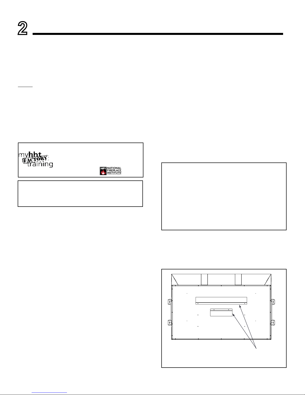
C. Inspect Appliance and Components
• Carefully remove the appliance and components from
the packaging.
• NOTE: Remove rear packaging brackets (2) before
installing unit. See Figure 2.1.
• The accessories and fronts may be shipped in separate
packages.
• Media may be packaged separately.
• Report to your dealer any parts damaged in shipment,
particularly the condition of the glass.
• Read all of the instructions before starting the installation. Follow these instructions carefully during the
installation to ensure maximum safety and benet.
WARNING! Risk of Fire or Explosion! Damaged parts
could impair safe operation. DO NOT install damaged, incomplete or substitute components. Keep appliance dry.
B. Tools and Supplies Needed
Before beginning the installation be sure that the following
tools and building supplies are available.
• Tape measure
• Pliers
• Hammer
• Gloves
• Voltmeter
• Level
• Manometer
• Framing material
• Phillips screwdriver
• Framing square
• Plumb line
• Safety glasses
• Reciprocating saw
• Flat blade screwdriver
• 1/2 - 3/4 in. length, #6 or #8 Self-drilling screws
• Non-corrosive leak check solution
• Electric drill and bits (1/4 in. magnetic)
• External regulator (for propane/LPG only)
• Piping which complies with local codes
• Pipe sealant approved for use with propane/LPG
(Resistant to sulfur compounds)
Hearth & Home Technologies disclaims any responsibility
for, and the warranty will be voided by, the following actions:
• Installation and use of any damaged appliance.
• Modication of the appliance.
• Installation other than as instructed by Hearth & Home
Technologies.
• Installation and/or use of any component part not approved
by Hearth & Home Technologies.
Any such action may cause a re hazard.
WARNING! Risk of Fire, Explosion or Electric Shock!
DO NOT use this appliance if any part has been under
water. Call a qualied service technician to inspect the
appliance and to replace any part of the control system
and/or gas control which has been under water.
• Manual shutoff valve
• Sediment trap
• Tee joint
• Pipe wrench
Rear View
Remove brackets before
installation and replace
screws
Figure 2.1 Bracket Removal
Page 6

6
Monessen • AVFL60 Installation Manual • 4605-901 Rev. A • 05/17
D. Getting Started
Verify that all listed parts have been received. You should
have the following:
• Unvented gas heater
• Two (2) anchoring screws
• Installation and Owner’s instructions
• 6" non-combustible board
• Deector glass
• Five (5) bags reglass
• Two (2) 90 watt bulbs
• RC300 remote control
Carefully inspect the contents for shipping damage. If any
parts are missing or damaged, immediately inform the
dealer from whom you purchased the appliance. Do not
attempt to install any part of the appliance unless you
have all parts in good condition.
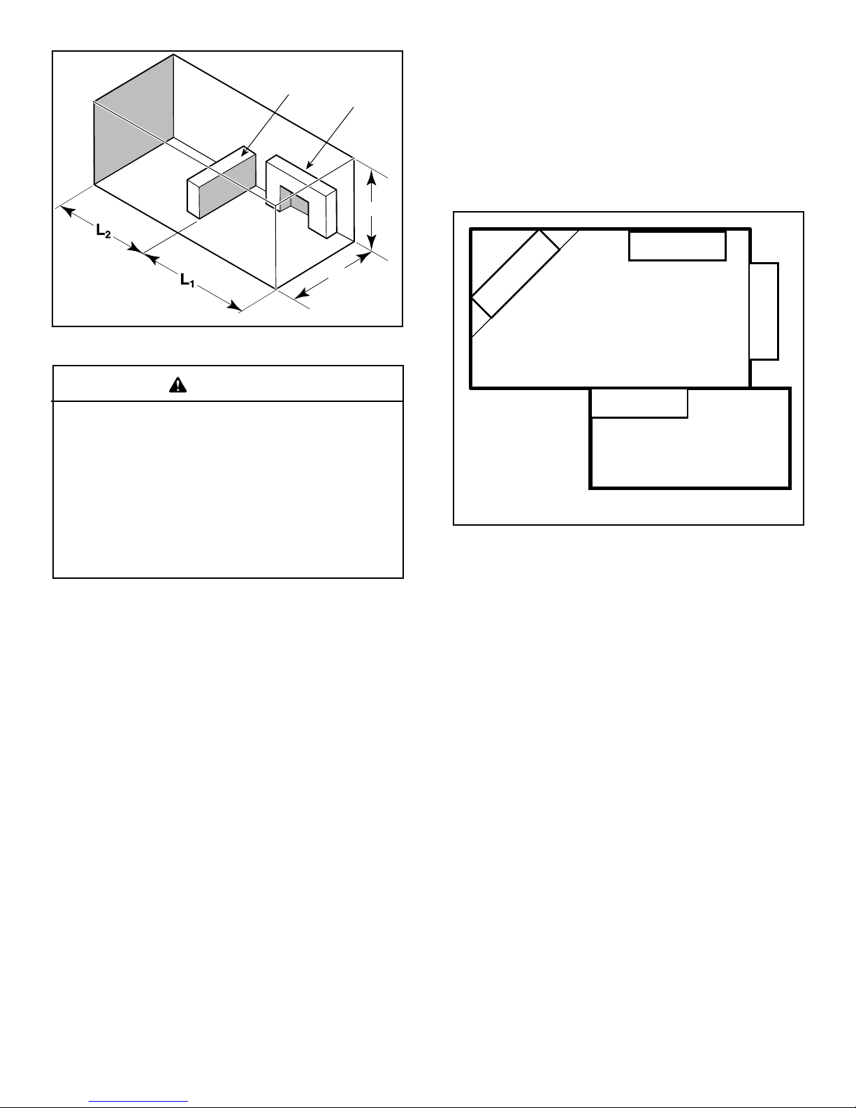
F. Adequate Combustion Ventilation Air
This heater shall not be installed in a conned space or
unusually tight construction unless provisions are provided
for adequate combustion and ventilation air.
The National Fuel Gas Code, (ANSI Z223.1/NFPA54),
denes a conned space as a space whose volume is less
than 50 cubic feet per 1,000 BTU per hour (4.8m
3
per kw)
of the aggregate input rating of all appliances installed in
that space, and an unconned space as a space whose
volume is not less than 50 cubic feet per 1,000 BTU per
hour (4.8 m3 per kw) of the aggregate input rating of all
appliances installed in that space. Rooms communicating
directly with the space in which the appliances are installed,
through openings not furnished with doors, are considered
a part of a conned space.
Unusually tight construction is dened as construction
where:
a. Walls and ceilings exposed to the outside atmosphere
have a continuous water vapor retarder with a rating of
1 perm (6 x 10
11
kg per pa/sec-m2) or less with openings
gasketed or sealed, and
b. Weather stripping has been added to windows and
doors, and
c. Caulking or sealants are applied to areas such as joints
around window and door frames, between sole plates
and oors, between wall-ceiling joints, between wall
panels, at penetrations for plumbing, electrical and gas
lines and other openings.
The following formula can be used to determine the maxi-
mum heater rating per the denition of unconned space:
BTU/Hr = (L1 + L2) Ft x (W) Ft x (H) Ft
50
Consider two connecting rooms with an open area
between, with the following dimensions:
L1 = 151/2 Ft., L2 = 12 Ft., W = 12 Ft., H = 8 Ft.
BTU/Hr = (151/2 + 12) x (12) x (8)
50
If there were a door between the two rooms the calculation
would be based only on the room with the heater.
BTU/Hr = (151/2) x (12) x (8)
50
Do not install the heater:
• Where curtains, furniture, clothing, or
other ammable objects are less than
36" from the front of the heater.
• In high trafc areas.
• In windy or drafty areas.
E. Planning the Installation
When planning the installation of the replace it is necessary to determine where the unit is to be installed and
whether optional accessories are desired. Gas supply
piping should also be planned. The following steps represent the normal sequence of installation. Each installation
is unique, however, and might require a different sequence.
1. Position replace in desired location. Refer to the Fire-
place Location (page 8, Figure 3.2) and Clearances
and Height Requirements (page 9, Figures 3.4 and 3.5)
sections and Fireplace and Framing Dimensions (page
8, Figure 3.2) illustration found in this manual.
NOTE: Be sure all packing material has been removed
from under and behind the unit.
2. Install following the instructions found in this manual.
3. Field wire main power supply to junction box. Refer to the
Electrical Installation section (page 19). (Electrical connections should only be performed by an experienced,
licensed certied service person).
4. Plumb gas line. Gas line may be run either through
bottom of unit or left side. There is no right side access.
Refer to the Connect the Gas (page 16, Figure 5.4)
section found in this manual. (Gas connections should
only be performed by an experienced, licensed/certied
service person).
5. Complete nish wall material and/or surround.
WARNING
WARNING
Gloves are recommended when handling
ceramic ber logs to prevent skin irritation
from loose bers. Logs are fragile—handle
with care.
Page 7
7
Monessen • AVFL60 Installation Manual • 4605-901 Rev. A • 05/17
W
H
Counter
Fireplace
If the area in which the heater may be
operated does not meet the required volume
for indoor combustion air, combustion and
ventilation air shall be provided by one
of the methods described in the National
Fuel Gas Code, ANSI Z223.1/NFPA 54, the
International Fuel Gas Code or applicable
local codes.
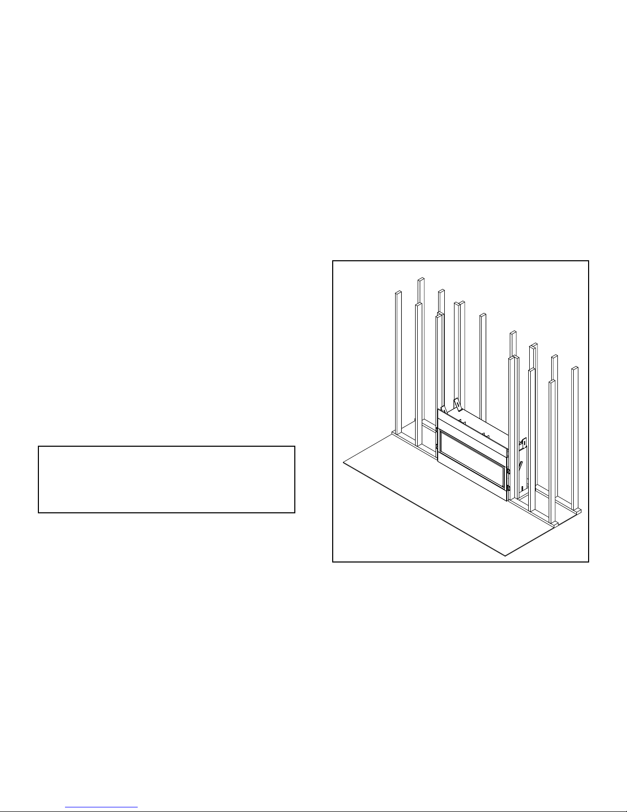
Figure 2.12
FIREPLACE LOCATION
This unvented gas heater requires no outside venting and
burns cleanly and efciency. As a zero-clearance unvented
gas heater, it can be installed against (or recessed into)
any wall that is accessible to a gas line.
Carefully select the best location for installation of your
unvented replace. The following factors should be taken
into consideration.
• Clearance to side wall, ceiling, woodwork and window
or other combustibles. Refer to Clearance and Height
Requirements section on Page 9. Minimum clearances
to combustibles must be maintained.
• Location must not be affected by drafts caused by
kitchen exhaust fans, ceiling fans, return air registers
for forced air furnaces / air conditioners, windows or
doors.
• Installation must provide adequate ventilation and
combustion air.
• DO NOT INSTALL THIS MODEL IN A BEDROOM
OR BATHROOM.
• Location should be out of high trafc areas and
away from furniture and draperies due to heat from
rebox.
Figure 2.3
• Never obstruct the front opening of the unvented re-
place or restrict the ow of combustion and ventilation
air.
• Minimize modications to existing construction. Refer
to Figure 2.2 below for location suggestions.
• Do not install in the vicinity where gasoline or other
ammable liquids may be stored. The unvented rebox must be kept clear and free from the combustible
materials.
NOTICE: Illustrations reect typical installations and are
FOR DESIGN PURPOSES ONLY. Illustrations/diagrams
are not drawn to scale. Actual installation could vary due
to individual design preference.
It is important to follow the framing and nishing instructions step by step to ensure proper placement of replace
in the surrounding framing/nishing materials.
WARNING
Page 8
8
Monessen • AVFL60 Installation Manual • 4605-901 Rev. A • 05/17
3
Framing and Clearances
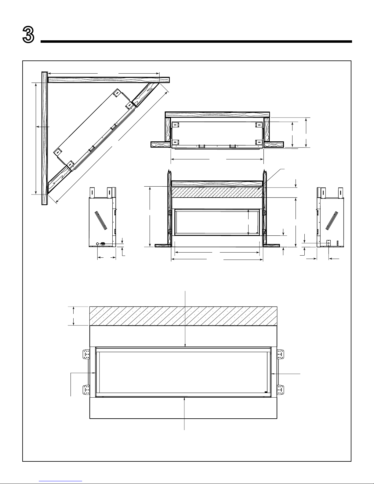
Figure 3.1 Fireplace and Framing Dimensions
A. Fireplace and Framing Dimensions
Figure 3.2 - Optional Facing Installation
"
NON COMBUSTIBLE BOARD
SUPPLIED
16-1/8”
18”
55-7/8”
67-3/16”
67-3/16”
95”
11”
1-7/8”
36-3/8”
51”
55-3/8”
16”
6”
6-7/8”
29-3/4”
2-3/8”
7”
Corner Framing
Gas
Rough
Opening
Height
Rough Opening Width
Rough
Opening
Depth
Actual
Actual
Actual
Electrical
View
NON-COMBUSTIBLE
NON-COMBUSTIBLE
6”
ONLY NON-COMBUSTIBLE
MATERIAL ON FACE OF UNIT.
ONLY
NON-COMBUSTIBLE
MATERIAL ON FACE
OF UNIT.
ONLY NON-COMBUSTIBLE
MATERIAL ON FACE OF UNIT.
ONLY
NON-COMBUSTIBLE
MATERIAL ON FACE
OF UNIT.
Page 9
9
Monessen • AVFL60 Installation Manual • 4605-901 Rev. A • 05/17
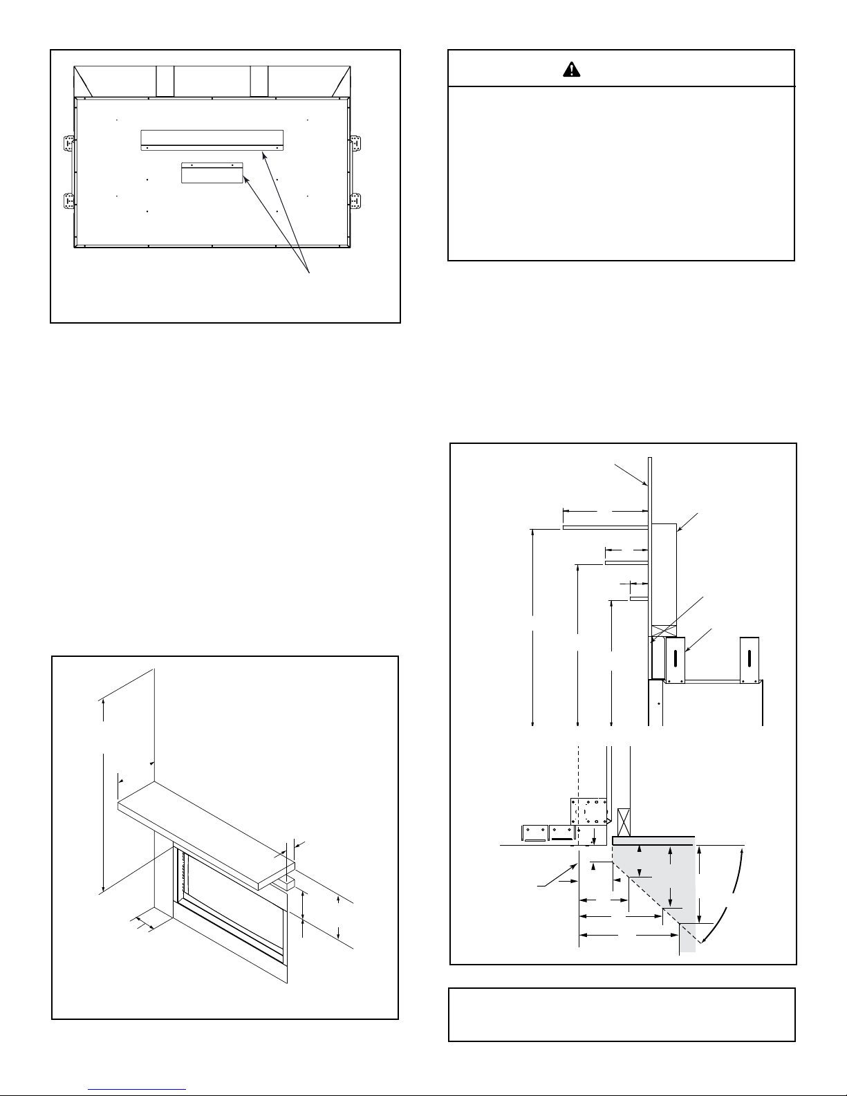
B. Clearances and Height Requirements
Ensure that minimum clearances shown in Figures 3.4
and 3.5 are maintained. Left and right clearances are
determined when facing the front of the rebox.
Follow these instructions carefully to ensure safe installation. Failure to follow these requirements may create a
re hazard.
Sidewall Clearances — The clearance from the inside of
the appliance to any combustible adjacent wall should not
be less than 6". Figure 3.4.
Ceiling Clearance — The ceiling or any other combustible
material must be at least 36" from the rebox opening.
Figure 3.4
Back Wall Clearance — The appliance may be placed
against a combustible back wall.
The dimensions shown in Figures 3.4 and
3.5 are minimum clearances to maintain
when installing this heater. Left and right
clearances are determined when facing the
front of the heater.
Follow these instructions carefully to
ensure safe installation. Failure to follow
instructions exactly can create a re hazard.
Floor Clearance — The replace may be installed directly
on a combustible oor or a raised platform of an appropriate height. Do not place replace on carpeting, vinyl, tile or
other soft oor coverings. It may, however, be placed on at
wood, plywood, particle board or other hard surfaces. Be
sure replace rests on a solid continuous oor or platform
with appropriate framing for support so that no cold air can
enter from under the rebox.
Mantel clearances — Must meet the clearance requirements detailed in Figures 3.4 and 3.5.
Figure 3.4 Sidewall and Ceiling Clearances
Figure 3.5 – Mantel Clearances
28"
6"
18"
12"
23"
Wall
Stud
Insulation
Board
Stando
2-1/2"
SIDE VIEW
6"
5"
3"
4¹⁄₂"
45°
1"
3¹⁄₂"
1¹⁄₂"
2¹⁄₂"
Fireplace
Opening
TOP VIEW
36" Minimum
From Opening
12
" Max.
Depth
2
1
/2" Max
Depth
18
" Min.
From Opening
28
" Min.
From Opening
6
" Min.
Rear View
Remove brackets before
installation and replace
screws
Figure 3.3 Bracket Removal
WARNING
See Good Faith Guidelines for TV Installations on
page 10, Figure 3.6.
Page 10
10
Monessen • AVFL60 Installation Manual • 4605-901 Rev. A • 05/17
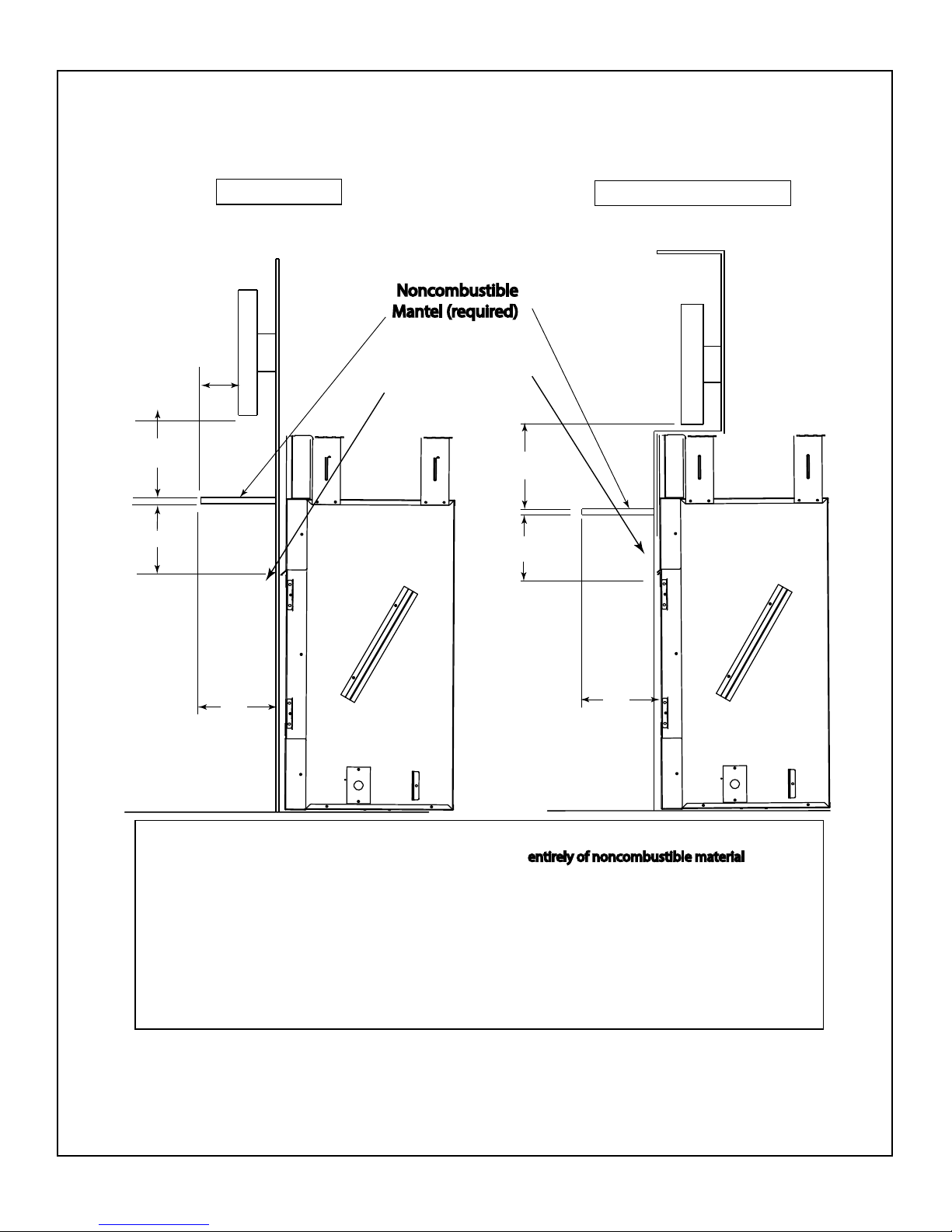
Figure 3.6 Good Faith TV Guidelines
C. Good Faith Wall Surface TV Guidelines
Good Faith Guidelines for TV Installaons above a Typical Gas Fireplace
Notes:
1. TV installation as shown requires the mantel be constructed entirely of noncombustible material
as it is below the allowable height for a combustible mantel.
2. These are good faith recommended clearances only and not a guarantee of compliance with all TV
manufacturers’ maximum allowable operating temperatures.
3. Since every home has unique air ow characteristics and maximum allowable operating temperatures
can vary from manufacturer to manufacturer and from model to model, actual TV temperatures should be
validated at the time of each installation. TVs should not be used in situations where the actual TV
temperature exceeds the manufacturers’ maximum allowable operating temperatures identied in the
TV’s technical specications. Contact the TV’s manufacturer directly if you cannot locate this information
or have questions regarding the information.
TV on the wall
TV recessed into the wall
TV
TV
6” Min.
4” Min.
12”
Min.
28”
4” Min.
28”
12”
Min.
Measured from top
of rebox opening.
Noncombustible
Mantel (required)
Page 11
11
Monessen • AVFL60 Installation Manual • 4605-901 Rev. A • 05/17
E. Floor Protection
NOTICE: Install appliance on hard metal or wood surfaces
extending full width and depth. DO NOT install directly
on carpeting, vinyl, tile or any combustible material other
than wood.
WARNING! Risk of Fire! Maintain specied air space
clearances to appliance and vent pipe:
• Insulation and other materials must be secured to prevent
accidental contact.
• The chase must be properly blocked to prevent blown
insulation or other combustibles from entering and
making contact with replace or chimney.
• Failure to maintain airspace could cause overheating
and re.
Figure 3.7 Floor Protection
D. Constructing the Appliance Chase
A chase is a vertical box-like structure built to enclose the
gas appliance.
NOTICE: Construction of the chase may vary with the type
of building. These instructions are not substitutes for the
requirements of local building codes. Therefore, you MUST
check local building codes to determine the requirements
to these steps.
Chases should be constructed in the manner of all outside walls of the home to prevent cold air drafting prob-
lems. The chase should not break the outside building
envelope in any manner.
Walls, ceiling, base plate and cantilever oor of the chase
should be insulated. Vapor and air inltration barriers
should be installed in the chase as per regional codes for
the rest of the home. Additionally, in regions where cold
air inltration may be an issue, the inside surfaces may be
sheet rocked and taped (or an equivalent method may be
used) to achieve maximum air tightness.
To further prevent drafts, the wall shield and ceiling re-
stops should be caulked with caulk with a minimum of
300ºF continuous exposure rating to seal gaps. Gas line
holes and other openings should be caulked with caulk
with a minimum of 300ºF continuous exposure rating or
stuffed with unfaced insulation. If the appliance is being
installed on a cement surface, a layer of plywood may be
placed underneath to prevent conducting cold up into the
room.
Note: Figure 3.4 and Figure 3.5, and Figure 3.7 show the
replace installed on the oor. However, this replace can
be elevated off the oor provided that the replace is properly
supported by framing materials and the ceiling clearances are
maintained.
Page 12

12
Monessen • AVFL60 Installation Manual • 4605-901 Rev. A • 05/17
4
Appliance Preparation
A. Securing and Leveling the Appliance
WARNING! Risk of Fire! Prevent contact with:
• Sagging or loose insulation
• Insulation backing or plastic
• Framing and other combustible materials
Block openings into the chase to prevent entry of blownin insulation. Make sure insulation and other materials
are secured.
DO NOT notch the framing around the appliance
standoffs. Failure to maintain air space clearance could
cause overheating and re.
To properly position, level, and secure the appliance, see
below. Nailing tabs are provided to secure the appliance
to the framing members.
• Bend out the two nailing tabs on each side.
• Place the appliance into position.
• Keep nailing tabs ush with the framing. See Figure 4.2.
• Level the appliance from side to side and front to back.
• Shim the appliance as necessary. It is acceptable to use
wood shims underneath the appliance.
• Secure the appliance to the framing by using nails or
screws through the nailing tabs.
Some gures in manual show the replace installed on the
oor. However, this replace can be elevated off the oor
provided that the replace is properly supported by framing
materials and the ceiling clearances are maintained.
Figure 4.2 Securing Fireplace to Framing
Combustible
Material
Framing Members
6 in.
Nailing Flange
Nailing Flange
Nailing Flange
Screws
Screws
Figure 4.1 Noncombustible Facing Installation
6"
MOUNTING
POINTS
55-3/8"
Standoffs
35-3/4"
Framing
55-7/8"
Page 13

13
Monessen • AVFL60 Installation Manual • 4605-901 Rev. A • 05/17
Setting the Fireplace into the Framing
The left and right nailing tabs were designed as a means
to ensure the replace is mounted ush with the framing
materials. See Figures 4.2 and 4.3.
1. Bend out all nailing tabs. The AVFL60 has four nailing
tabs, two on each side in the middle of the unit.
2. Screw each nailing tab to the adjoining framing material. See Figures 3.1-3.7 for framing and clearance
details.
Figure 4.3 Nailing Tabs
Figure 4.4 Install Non-Combustible Facing Material
B. Installing Non-Combustible Facing Material
WARNING! Risk of Fire!
• Follow these instructions exactly.
• Facing materials must be installed properly to prevent
re.
• No materials may be substituted without authorization
by Hearth & Home Technologies.
• Non-Combustible facing material needs to be at least 6”
high and the full width of the unit.
• Attach non-combustible facing material to the framing
members with regular sheetrock screws.
• Use a wet or dry towel or soft brush to remove dust or
dirt from facing material.
• See Section 8 for nishing materials guidelines.
Page 14

14
Monessen • AVFL60 Installation Manual • 4605-901 Rev. A • 05/17
A. Fuel Type
• This appliance is equipped for either natural or propane
gas. Field conversion is not permitted.
• Make sure the appliance is compatible with available gas
types.
B. Gas Pressure
• Optimum appliance performance requires proper input
pressures.
• Gas line sizing requirements will be determined in ANSI
Z223.1 National Fuel Gas Code in the USA.
• Pressure requirements are:
5
Gas Information
Note: Have the gas supply line installed in accordance with
local codes, if any. If not, follow ANSI 223.1. Installation
should be done by a qualied installer approved and/or
licensed as required by the locality. (In the Commonwealth
of Massachusetts installation must be performed by a
licensed plumber or gas tter).
Note: A listed (and Commonwealth of Massachusetts ap-
proved) 1/2 in. (13 mm) T-handle manual shut-off valve
and exible gas connector are connected to the 1/2 in. (13
mm) control valve inlet.
• If substituting for these components, please consult
local codes for compliance.
Fire Risk.
Explosion Hazard.
High pressure will damage valve.
• Disconnect gas supply piping BEFORE
pressure testing gas line at test pressures
above 1/2 psig.
• Close the manual shutoff valve BEFORE
pressure testing gas line at test pressures
equal to or less than 1/2 psig.
WARNING
WARNING! Risk of Fire or Explosion! High pressure
will damage valve. Low pressure could cause explosion.
• Verify inlet pressures. Verify minimum pressures when
other household gas appliances are operating.
• Install regulator upstream of valve if line pressure is
greater than 1/2 psig.
• Valve pressure taps are accessible by removing the
control door. See Figures 5.1 & 5.2.
Figure 5.1. Valve Pressure Tap
NOTE: This appliance does include a manual gas shutoff
valve that is located in the valve compartment. This manual
gas shutoff valve is accessible for service by removing the
con tro l doo r. See Fi gur e 5.2 . The valve is most accessible
if it is located forward in the control cavity of the appliance.
Depending upon local code, an additional manual gas
shutoff, in a readily accessible area may be required and
located upstream from the appliance.
C. Gas Service Access
NATURAL PROPANE (LP)
Inlet Minimum 5.0" w.c. 11.0" w.c.
Inlet Maximum 10.5" w.c. 13.0" w.c.
Regulator Pressure
Setting
3.5" w.c. 10" w.c.
Pilot Regulator 3.5" w.c. —
TEST PORT "A"
Page 15

15
Monessen • AVFL60 Installation Manual • 4605-901 Rev. A • 05/17
Led
Buttons
Valve
Control
Module
ODS
Module
ODS
Adapter
Battery
Backup
Aux
Figure 5.2 Valve Access
Page 16

16
Monessen • AVFL60 Installation Manual • 4605-901 Rev. A • 05/17
D. Connect to Gas
NOTICE: A qualied gas appliance installer must connect
the heater to the gas supply. Consult all local codes.
Use new black iron or steel pipe. Internally
tinned copper or copper tubing can be used
per National Fuel Code, section 2.6.3, providing
gas meets hydrogen sulde limits, and where
permitted by local codes. Gas piping system
must be sized to provide minimum inlet
pressure (Listed on Data Plate) at the maximum
ow rate (BTU/hr). Undue pressure loss will
occur if the pipe is too small.
A manual shutoff valve must be installed
upstream of the appliance. Union tee and
plugged 1⁄8" NPT pressure tapping point should
be installed upstream of the appliance. Figure
5.3
A sediment trap should be installed upstream
to prevent moisture and contaminants from
passing through the pipe to appliance controls
and burners. Failure to do so could prevent the
appliance from operating reliable. Figure 5.3
IMPORTANT: Loosen the pipe adapter on the ex tube
before installing to the system piping.
Always use an external regulator for all propane/LPG heat-
ers only, to reduce the supply tank pressure to a maximum
of 13" w.c. This is in addition to the internal regulator in the
heater valve.
When tightening the joint to the valve, hold the valve
securely to prevent movement.
Test all gas joints from the gas meter to the heater valve for
leaks using a gas analyzer or soap and water solution after
completing connection. DO NOT USE AN OPEN FLAME.
CHECK GAS TYPE: The gas supply must be the
same as stated on the heater’s rating plate. If
the gas supply is different, DO NOT INSTALL
THE HEATER. Contact your dealer for the
correct model.
Connecting directly to an unregulated
propane/LP tank can cause an explosion.
DO NOT USE OPEN FLAME TO CHECK
FOR GAS LEAKS.
GAS LINE IN
GAS LINE IN
Figure 5.3 Gas Line In
When an appliance is connected to a xed piping system, the installation must conform with local codes,or in
the absence of local codes with the National Fuel Gas
Code, ANSI Z223.1/NFPA 54 or International Fuel Gas
Code.
THIS APPLIANCE IS EQUIPPED FOR
EITHER NATURAL OR PROPANE GAS.
FIELD CONVERSION IS NOT PERMITTED.
WARNING
WARNING
WARNING
WARNING
Page 17

17
Monessen • AVFL60 Installation Manual • 4605-901 Rev. A • 05/17
E. Valve Access
The valve and controls are located in the appliance con-
trol box. See Figure 5.4.
The control box and controls can be accessed by lifting
engine assembly and shown in Figure 5.4.
• Make sure unit is off and cool.
• Remove media and deection glass panel from
hearth pan.
• Remove two (2) screws securing burner assembly to
appliance, set aside.
• Lift the burner assembly and place the two engine
supports, provided under the Engine, against lower
front space at the bottom of the face, and slide into
the slots at the bottom of the engine assembly. See
Figure 5.4.
• Locate valve on face of engine assembly.
• Gas line sizing requirements will be determined in
ANSI Z233.1 National Fuel Gas Code in the USA.
• Pressure requirements are:
These pressures can be veried by lifting engine and
removing control cover to reveal the valve.
When an appliance is connected to a xed piping sys-
tem, the installation must conform with local codes,or in
the absence of local codes with the National Fuel Gas
Code, ANSI Z223.1/NFPA 54 or International Fuel Gas
Code.
Engine Support
Figure 5.4 Valve Access
F. Check Gas Pressure
Check the gas pressure with the appliance burning and
the control set to HIGH.
Open control access door at bottom front of unit to nd
valve and regulator referred to below.
The valve regulator controls the burner pressure which
should be checked at the pressure test point.
Turn captured screw counterclockwise two or three turns
and then place tubing to pressure gauge over test point.
Use test point “A” closest to gas inlet. After taking pres-
sure reading, be sure and turn captured screw clockwise
rmly to reseal. Do not over torque. Check for gas leaks.
See Figure 5.5.
TEST PORT 'A'
Figure 5.5 Pressure Test Point Location
Screen
Access
Panel
Figure 5.6 Gas and Electrical Access - Remove Screen
Page 18

18
Monessen • AVFL60 Installation Manual • 4605-901 Rev. A • 05/17
Figure 5.7 Gas Fitting Access
G. Gas Connection
• Refer to Figure 5.7 for location of gas ex line access in
appliance.
• Gas line may be run through the left side or right bottom
of the appliance. See Figure 5.3.
• The gap between supply piping and gas access hole
may be caulked with caulk with a minimum of 300ºF
continuous exposure rating or stuffed with noncombustible, unfaced insulation to prevent cold air
inltration.
• Ensure that gas line does not come in contact with outer
wrap of the appliance. Follow local codes.
• Pipe incoming gas line into valve compartment.
• Connect incoming gas line to the 1/2 in. (13 mm)
connection on manual shutoff valve.
WARNING! Risk of Fire or Explosion! Support control
when attaching pipe to prevent bending gas line.
• A small amount of air will be in the gas supply lines.
WARNING! Risk of Fire or Explosion! Gas build-up during line purge could ignite.
• Purge should be performed by qualified service
technician.
• Ensure adequate ventilation.
• Ensure there are no ignition sources such as sparks
or open ames.
H. High Altitude Installations
NOTICE: If the heating value of the gas has been reduced,
these rules do not apply. Check with your local gas utility
or authorities having jurisdiction.
When installing above 4500 feet elevation reduce input
4% for each 1000 feet above 4500 feet.
Check with your local gas utility to determine proper ori-
ce size.
Gas
Valve
Control
Module
Battery
Backup
Light the appliance. It will take a short time for air to purge
from lines. When purging is complete the appliance will
light and operate normally.
WARNING! Risk of Fire, Explosion or Asphyxiation!
Check all ttings and connections with a non-corrosive
commercially available leak-check solution. DO NOT use
open ame. Fittings and connections could have loosened during shipping and handling.
WARNING! Risk of Fire! DO NOT change valve settings.
This valve has been preset at the factory.
18" Flex Line
Page 19

19
Monessen • AVFL60 Installation Manual • 4605-901 Rev. A • 05/17
A. General Information
WARNING! Risk of Shock or Explosion! DO NOT wire
110-120 VAC to the valve or to the appliance wall switch.
Incorrect wiring will damage controls.
NOTICE: This appliance must be electrically wired and
grounded in accordance with local codes or, in the absence
of local codes, with National Electric Code ANSI/NFPA
70-latest edition.
• Wire the appliance junction box to unswitched 110-
120 VAC. This is required for proper operation of the
appliance.
• A 110-120 VAC circuit for this product must be protected
with ground-fault circuit-interrupter protection, in
compliance with the applicable electrical codes, when
it is installed in locations such as in bathrooms or near
sinks.
• Low voltage and 110/120 VAC voltage cannot be shared
within the same wall box.
6
Electrical Information
Electrical Service and Repair
WARNING! Risk of Shock! Label all wires prior to disconnection when servicing controls. Wiring errors can
cause improper and dangerous operation. Verify proper
operation after servicing.
WARNING! Risk of Shock! Replace damaged wire with
type 105º C rated wire. Wire must have high temperature
insulation.
Junction Box Installation
WARNING! Risk of Shock! Label all wires prior to disconnection when servicing controls. Wiring errors can
cause improper and dangerous operation. Verify proper
operation after servicing.
WARNING! Risk of Shock! Replace damaged wire with
type 105° C rated wire. Wire must have high temperature
insulation.
Accessories Requirements
• This appliance may be used with a wall switch, or optional
wall mounted thermostat and/or a remote control.
Wiring for optional Hearth & Home Technologies approved
accessories should be done now to avoid reconstruction.
Follow instructions that come with those accessories.
Figure 6.1 Cover Plate for Junction Box
Junction Box Wiring
1. This should be done before framing the replace. Wire
the receptacle into an electrical circuit.
2. The junction box cover has a Romex style strain relief
connector located in the Owner’s Manual. After con-
necting the wires, route the wire leads through this
connector. Refer to the wiring diagram in Figure 6.2.
Electrical connections should only be performed
by a qualied, licensed electrician. Main power
must be off when connecting to main electrical
power supply or performing service. All wiring
shall be in compliance with all local, city and
state codes. The appliance, when installed,
must be electrically grounded in accordance
with local codes or in the absence of local
codes, with the National Electrical Code ANSI/
NFPA 70 (latest edition) and Canadian Electrical
Code, CSA C22.1.
CAUTION
Label all wires before disconnecting when
servicing controls. Wiring errors can cause
improper and dangerous operation.
Do not connect wall switch to 110 V circuit.
Figure 6.2 - Junction Box Wiring Diagram
120V AC
60Hz
Factory Supplied
Not Supplied
Junction Box
WARNING
WARNING
Page 20

20
Monessen • AVFL60 Installation Manual • 4605-901 Rev. A • 05/17
Figure 6.3 IntelliFire™ Plus ODS Wiring Diagram
B. Wiring Requirements
Intellire™ Plus ODS Ignition System Wiring
NOTICE: Batteries should only be used as a power source
in the event of an emergency power outage. Batteries
should not be used as a primary long-term power source.
Battery polarity must be correct when installing batteries.
When using batteries as a power source, the 6-volt
transformer must be unplugged from the receptacle.
Do not store batteries in the battery pack when the
appliance is powered by the 6 volt transformer connected
to permanent electrical service.
• Wire the appliance junction box to 110-120 VAC for
proper operation of the appliance.
WARNING! Risk of Shock or Explosion! DO NOT wire
IFP ODS controlled appliance junction box to a switched
circuit. Incorrect wiring will override IFP ODS safety lockout.
• Refer to Figure 6.3 or 6.4, IFP ODS Wiring Diagram.
• This appliance is equipped with an Intellire™ Plus
control valve which operates on a 6 volt/1.5 AMP system.
• Plug the 6 volt transformer plug into the appliance junction
box to supply power to the unit OR install 4 AA cell
batteries (not included) into the battery pack before use.
Accessories Requirements
• This appliance ships standard with a remote control.
Wiring for optional Hearth & Home Technologies approved
accessories should be done now to avoid reconstruction.
Follow instructions that come with those accessories.
TO JUNCTION
BOX (120V)
I
S
RC300 4.5V DC
(AAA X 3)
TO JUNCTION
BOX 120VAC
TO OPTIONAL
COMPONENTS
GROUND
ORANGE
(PILOT)
GREEN
(MAIN)
BROWN
BLACK
RED
BROWN/RED
OPTIONAL ON/OFF
SWITCH
BATTERY PACK
6V DC
FLAME
MODULATION
AUX300 MODULE
AUX 1
AUX 2
FAN
WHITE
ORANGE
CONTROL MODULE
6V DC
SUPPLY
PILOT
THERMOCOUPLE MODULE
19026-GM931 Control Box ODS
19093-Thermalcouple Module Wire
K19084 8K-1 Adapter Box
K99085 GM8K-1
ODS Adapter Box
THERMOCOUPLE
THERMOCOUPLE
SENSOR
SENSOR
Page 21

21
Monessen • AVFL60 Installation Manual • 4605-901 Rev. A • 05/17
Figure 6.4 Wiring Diagram
LED STRIP
LED STRIP
TRANSFORMER
CONTROL
MODULE
JUNCTION BOX
TOP BUTTON
ON/HI/MED/LO/OFF
BOTTOM BUTTON
Color Selection
RED
WHITE
YELLOW
BLACK
RED
BLACK
BLACK
BLACK
BLACK
BLACK
Page 22

22
Monessen • AVFL60 Installation Manual • 4605-901 Rev. A • 05/17
7
Final Installation
A. Dome Light Bulb Installation
NOTE: This unit is shipped without bulbs installed to pre-
vent any damage to the bulb lament during transport. This
unit is shipped with a total of two (2) 90W bulbs.
Dome Light Bulb Installation
CAUTION
Turn OFF the main power supply before performing any service work on the unit, including install-
ing or replacing light bulbs.
1. Remove three screws holding the left dome light
cover in place. See Figure 7.2.
Light cover
screws
Figure 7.1– Dome Light Position
Figure 7.2– Dome Light Screws
TOP LIGHT LOCATION
The Black Magic Glass liner is packaged and shipped
with the unit. Before install, remove the glass panels and
place on a at, clean surface and inspect for damage.
NOTE: Before beginning installation remove the two L
shaped brackets from the manual pack along with two #8
phillips head screws.
NOTE: After gas and electric are connected and the unit
has been test red the glass can be installed.
1. Place the rear glass panel against the rear wall of the
rebox, resting on top of the engine base. The dimples
in the glass will face the rebox.
2. Place the left side panel between the engine base
and rebox, resting on the botton of the rebox ledge.
Secure with supplied L bracket to the top of the rebox
witht the supplied screw.
3. Repeat step 2 on the right side.
NOTE: When removing the black glass from the unit, be
cautious of the rear panel falling forward once the side
panels are removed.
B. Black Magic Glass Installation
Figure 7.3 Black Magic Glass Installation
2. Insert (1) bulb provided into socket
3. Replace dome light cover with three screws
4. Repeat on right side light cover
Page 23

23
Monessen • AVFL60 Installation Manual • 4605-901 Rev. A • 05/17
C. Installation of Air Deection Glass
NOTE: If installing optional driftwood logs be sure to
install log pin brackets prior to installing air deection
glass or reglass. See pages 24 and 25 for instructions.
NOTE: The air deection glass must be installed prior
to placing any reglass or stone media on the burner. To
install the air deection glass simply place the edge of
the deection glass into the two position tabs (located at
the front of the engine base) and slide into ngers until
reaching the bottom of the tab slots, in front of the burner
ports. The glass should stand upright, neither leaning
forward nor backward.
NOTE: The optional stone kit and log kit are to be installed
alone and never in combination.
D. Fireglass Only Placement
NOTE: Five (5) bags of reglass are supplied with the
replace.
Figure 7.4– Air Deection Glass and Stone Placement
Both bags may be used to cover the entire oor and burner.
We advise against using additional reglass as too much
can cut off the proper amount of air the burner needs to
burn cleanly. This may cause sooting.
1. Spread reglass evenly in one layer over the entire oor
and burner. It is important to not have the reglass too
thick on ported area (single layer only).
2. Turn burner on and adjust reglass over ported areas
to achieve an even, clean ame.
E. Glass and Optional Stone Kit Placement
1. For best results, spread reglass evenly over the entire
oor and burner making sure the glass is not too thick
over the burner ports (single layer only). See Figure 7.4.
2. Place the stones randomly in front of and behind the
burner. CAUTION: Do not allow stones to sit directly
on burner or in ame. See Figure 7.4 and 7.5.
3. Turn burner on and adjust reglass over the ported area
to achieve an even, clean ame.
Example of stone accessory placement
Burner surface. DO NOT place stones in the gray shaded area.
Air deflection glass
Deection glass tabs
Page 24

24
Monessen • AVFL60 Installation Manual • 4605-901 Rev. A • 05/17
F. Placement of Optional Logs
WARNING: Turn off replace and allow to cool completely before beginning installation.
Kit Contents:
• Three driftwood logs
• Support pin brackets
• #8 bracket mounting screws
NOTE — Do not handle logs with your bare hands. Always
wear gloves to prevent skin irritation from logs. After
handling the logs, wash your hands with soap and water
to remove any traces of bers.
NOTE: Prior to installing the log set, you must rst install the
pin brackets on the burner. Fireglass and the air deection
glass should only be installed after the pin brackets are in
place. The logs must then be placed in the unit after the
reglass and air deection glass. If the optional logs are
added after the air deection glass and reglass are in use,
move the reglass away from the areas in Figure 7.6 and
install the support brackets, then arrange reglass evenly
across burner again.
The positioning of the logs is critical to the safe
and clean operation of this heater. Sooting and
other problems may result if the logs are not
properly and rmly positioned in the appliance.
Never add additional logs or embellishments
such as pine cones, vermiculite or rock wool to
the heater. Only use the logs supplied with the
optional log kit (AVFL60DLS).
Failure to position the parts in accordance with
diagrams below or to use only parts specically
approved for this heater may result in property
damage or personal injury.
1. Mount the four log support pin brackets using mounting holes and screws provided in locations indicated
in Figure 7.7.
2. Place the large rear log (#1) by aligning the holes in
the bottom of each log with the four pins at the back
of the burner. Logs are marked “Rear Left” and “Rear
Right” for easy identication.
Figure 7.5– Stone Placement
Figure 7.6– Log Pin Assembly
PIN PLACEMENT FOR
REAR LOGS
AIR DEFLECTION
GLASS
REAR
FRONT
Figure 7.7– Pin Placement for Accessory Logs
WARNING
Page 25

25
Monessen • AVFL60 Installation Manual • 4605-901 Rev. A • 05/17
3. The front driftwood log does not utilize a pin bracket.
This log can be placed behind the front deection glass
with the area marked on the gure below. THIS LOG
CAN ONLY BE PLACED WITHIN THIS AREA. The
log cannot be placed on the burner area. It can be
adjusted left to right as desired. See Figure 7.8.
FRONT LOG
PLACEMENT
AREA
DO NOT PLACE LOGS
IN THIS AREA
REAR LOG
PINS
REAR
FRONT
Figure 7.8– Log Placement
Page 26

26
Monessen • AVFL60 Installation Manual • 4605-901 Rev. A • 05/17
G. Lighting Instructions (IPI)
4604-200
FOR YOUR SAFETY READ BEFORE LIGHTING
TO TURN OFF GAS TO APPLIANCE
1. Equipped with wall switch: Turn ON/OFF switch to OFF.
Equipped with remote or wall control: Press OFF button.
Equipped with thermostat: Set temperature to lowest setting.
WARNI NG: If you do not follow these instructions exactly, a fi re or explosion may result causing property damage, personal injury or loss of life.
GAS
VALVE
A. This appliance is equipped with an intermittent pilot ignition (IPI) device which
automatically lights the burner. DO NOT try to light the burner by hand.
B. BEFORE LIGHTING, smell all around the appliance area for gas. Be sure to smell
next to the fl oor because some gas is heavier than air and will settle on the fl oor.
WHAT TO DO IF YOU SMELL GAS
• DO NOT try to light any appliance.
• DO NOT touch any electric switch; do not use any phone in your building.
• Immediately call your gas supplier from a neighbor’s phone. Follow the gas supplier’s instructions.
• If you cannot reach your gas supplier, call the fi re department.
C. DO NOT use this appliance if any part has been under water. Immediately call
a qualifi ed service technician to inspect the appliance and to replace any part of
the control system and any gas control which has been under water.
LIGHTING INSTRUCTIONS (IPI)
2. Wait fi ve (5) minutes to clear out any gas. Then smell for gas, including near the
fl oor. If you smell gas, STOP! Follow “B” in the Safety Information located on the
top of this label. If you do not smell gas, go to next step.
3. To light the burner:
Equipped
with wall switch: Turn ON/OFF switch to ON.
Equipped with remote or wall control: Press ON or FLAME button.
Equipped with thermostat: Set temperature to desired setting.
4. If the appliance does not light after three tries, call your service technician or gas
supplier.
2. Service technician should turn off electric power to the control when performing
service.
1. This appliance is equipped with an ignition device which automatically
lights the burner. DO NOT try to light the burner by hand.
4604-201
.
WARNING:
NOT FOR USE WITH SOLID FUEL
DO NOT CONNECT LINE VOLTAGE (110/120 VAC OR 220/240 VAC) TO THE CONTROL VALVE.
Improper installation, adjustment, alteration, service or maintenance can cause
injury or property damage. Refer to the owner’s information manual provided with
this appliance. For assistance or additional information, consult a qualifi ed installer,
service agency or the gas supplier.
This appliance needs fresh air for safe operation and must be installed so there are
provisions for adequate combustion and ventilation air.
Keep burner and control compartment clean. See installation and operating instructions accompanying appliance.
Hot while in operation. DO NOT touch. Keep children, clothing, furniture, gasoline
and other liquids having fl ammable vapors away.
,enon fi ;yna fi ,sedoc lacol htiw ecnadrocca ni dellatsni eb tsum ecnailppa sihT
follow the National Fuel Gas Code, ANSIZ223.1/ NFPA 54, or the National Gas and
Propane Installation code, CSA B149.1.
CAUTION:
For additional information on operating your
Hearth & Home Technologies fi replace, please refer to www.fi replaces.com.
Page 27

27
Monessen • AVFL60 Installation Manual • 4605-901 Rev. A • 05/17
8
Finishing
A. Facing and Finishing Instructions
WARNING! Risk of Fire! Comply with all minimum clear-
ances to combustibles as specied. Framing closer than the
minimums listed must be constructed entirely of noncombustible materials (i.e., steel studs, concrete board, etc.).
Finishing Instructions
It is important to follow the framing and nishing instructions to ensure proper placement of replace into the surrounding framing/nishing materials.
Wall sheathing materials 1/2 in. thick are specied in
this installation manual to properly align with the non-
combustible material.
WARNING! Risk of Fire! Non-combustible board MUST
be installed. DO NOT remove or cover it with combustible
material, such as:
• Drywall (gypsum board)
• Plywood
• Materials that do not meet the ASTM E 136 Non-combustibility standard (below).
Removal of installed, non-combustible board and/or use
of materials not meeting the ASTM E 136 standard could
cause re.
Non-Combustible Materials Specication
Material which will not ignite and burn. Such materials are
those consisting entirely of steel, iron, brick, tile, concrete,
slate, glass or plasters, or any combination thereof.
Materials that are reported as passing ASTM E 136,
Standard Test Method for Behavior of Materials in a
Vertical Tube Furnace at 750 ºC.
WARNING! Risk of Fire! Maintain specied air space
clearances to combustibles. Inadequate air space could
cause overheating and re.
NOTICE: The maximum nishing material not only includes
the decorative nish materials (marble, tile, slate, etc) but
also the thin set, lath, and adhesive used to attach the
decorative nish material.
Finishing Materials
This section discusses installation details associated
with the Inside and Overlap Fit methods and species
additional non-combustible materials required.
NOTICE: Surface temperatures around the appliance will
become warm while the appliance is in operation. Ensure
finishing materials used for all surfaces (floor, walls,
mantels, etc.) will withstand temperatures up to 190°F.
Tape wall board joints around the replace opening with
berglass-mesh tape. It will provide a more crack-resistant joint than paper tape. Fill, smooth and nish wall
joints with chemically setting-type joint compound. It will
provide a more crack-resistant joint than air-drying light-
weight compound.
Finish and Sealing Joints
All joints between the nished wall sheathing and the appliance must be sealed with non-combustible materials.
Sealants, such as caulk or mastic used to seal the gap
between the wall and the replace, should be rated at a
minimum continuous exposure to 300ºF.
Painting
If desired nishing includes a painted wall, 100% acrylic
latex with compatible primer is recommended around this
appliance. Oil-based or standard acrylic paints may discolor due to heat exposure.
The appliance is designed to mate with 1/2 in. wall
sheathing materials such as drywall, plywood, wood
composites, or non-combustible materials.
• Finishing Around Perimeter of Unit (Install Option
#1)
Gypsum wallboard (drywall) joints can be nished up to
the perimeter of the left, right and bottom edge of the unit
ush with the face. The 6” of suppied nom-combustible
must be used at the top of the unit where the gypsum
board can then be nished to the left, right and top edge
of the non-combustible board.
• Finishing Around Opening of Unit (Install Option #2)
NOTE: With this installation option, the unit must be
recessed to the depth of the non-combustible being used
to ensure nish is ush with surrounding wall. This is
the recommended install option for all trim kits such as
the AVFL60TKI, AVFL60CFCV, AVFL60CFBT. Refer
to Trim Kit instructions for Option #2 installation before
starting.
The 6” non-combustible must rst be installed above
the unit in the same manor as insatllation option #1,
ush with the top face of the unit. In this option, non-
combustible is required for all material covering the face
of the unit. The non-combustible may be installed up to
the rebox opening but must not overlap which would
impede the removal of the screen. When installing
material around the rebox opening, install the sheet
with a pre-cut hole for the rebox opening in a single
sheet, if possible. This will minimize joints across the
replace face and reduce cracking.
Page 28

28
Monessen • AVFL60 Installation Manual • 4605-901 Rev. A • 05/17
To Reduce the Risk of Sheetrock Cracking:
DO
Use all purpose joint compound.
Use eggshell paint
(100% acrylic latex paint, gloss or semi-gloss).
To Avoid Sheetrock Cracking:
DO NOT
Use a quick set or light weight joint compound.
Use at paint.
In extreme cases, lab tests have shown yellow pigments
fading out of paints over time due to heat. Vent run and
installation location will have an effect on wall temperature
and fading. If fading occurs, consider avoiding paint that
contains yellow pigment.
In regards to the sheetrock mud, apply a smooth, even
layer, covering a wide area of the wall for the best results.
For best results, follow the tips below.
WARNING! Risk of Fire! DO NOT apply combustible
materials beyond the minimum clearances. Comply with
all minimum clearances to combustibles as specied in
this manual. Overlapping materials could ignite and will
interfere with proper operation of doors and louvers.
WARNING! Risk of Fire! DO NOT install drywall or
other combustible materials directly onto the installed
non-combustible board. Overlapping materials could
ignite.
Finish with non-combustible
up to unit opening. Cannot
cover the opening so that
screen can be removed.
NON-COMBUSTABLE
NON-COMBUSTABLE
6”
Install
Option #2
Install
Option #1
Install
Option #1
Install
Option #2
Install
Option #1
(page 27)
Install
Option #2
(page 27)
Install
Option #1
Install
Option #2
Figure 8.1 - Finishing Around Unit
Page 29

29
Monessen • AVFL60 Installation Manual • 4605-901 Rev. A • 05/17
NOTICE: Some functionality will be lost when using
battery backup including remote control, lights, or any
other auxiliary functions that require household 110-120
VAC power.
B. Operation During A Power Outage
NOTICE: Batteries should only be used as a power source
in the event of an emergency power outage. Batteries
should not be used as a primary long-term power source.
The IntelliFire™ Plus ODS intermittent pilot ignition system
comes with a battery backup system that enables the
system to operate in a power outage. The system offers
seamless transition from household AC power to battery
backup. A factory-installed battery pack is located in the
control cavity of the appliance. See Figure 8.2. Battery
longevity and performance will be affected by long term
exposure to the service temperatures of this appliance.
To Operate Fireplace Using Battery Power (DC):
1. Access the control cavity of the appliance. See
Figure 8.2 for location. Lift the screen frame off of
the appliance and lift the access panel out of the front
edge of the unit..
2. Locate the battery tray and insert four AA cell batteries.
See Figure 8.2. Battery polarity must be correct or
module damage will occur. A complete wiring diagram
is included in the Electrical section of the appliance
Installation Manual.
3. Turn the appliance on according to the instructions
below for the appropriate type of control:
Standard Wall Switch or Factory-Installed ON/OFF
Switch:
• Toggle the switch as you would under normal
circumstances.
Wireless Remote:
• Remote receiver is integrated into the ignition module
• Use the remote to turn the appliance on.
• To preserve battery life, do not use the HI/LO ame or
THERMOSTAT options.
Ignition Module:
• Remove screws on left and right sides of component
heat shield and lift it out of the control cavity.
• Locate the ignition module in the control cavity.
• Slide the ON/REMOTE/OFF switch to the ON position.
• Reinstall component heat shield.
To Return to Operation Using Electrical (AC) Power
CAUTION! Risk of Overheating! Component heat shield
MUST be installed before operating appliance. Electrical
components will be damaged.
Standard Wall Switch or Factory-Installed ON/OFF
Switch:
• Remove screws on left and right sides of component
heat shield and lift it out of the control cavity.
• Toggle the switch to OFF.
• Remove the batteries from the battery tray.
• Reinstall component heat shield.
• Replace bottom glass shield and decorative front on
appliance.
Wireless Remote:
• Remove screws on left and right sides of component
heat shield and lift it out of the control cavity.
• Slide the ON/REMOTE/OFF switch to the REMOTE
position.
• Remove the batteries from the battery tray.
• Reinstall component heat shield.
• . Replace bottom glass shield and decorative front on
appliance.
Ignition Module:
• Remove screws on left and right sides of component
heat shield and lift it out of the control cavity.
• Slide the ON/REMOTE/OFF switch to the REMOTE
position.
• Remove the batteries from the battery tray.
• Reinstall component heat shield.
• . Replace bottom glass shield and decorative front on
appliance.
Control Cavity
(shown in gray)
Battery Tray
Control Module
Figure 8.2– Control Cavity Location
Page 30

30
Monessen • AVFL60 Installation Manual • 4605-901 Rev. A • 05/17
Figure 8.3 Control Module
Control Module Operation
1. The control module has an ON/OFF/REMOTE selector
switch that must be set. See Figure 8.3.
OFF Position: Appliance will ignore all power inputs and
will not respond to any commands from a wall switch or
remote. The unit should be in the OFF position during
installation, service, battery installation, fuel conversion,
and in the event that the control goes into LOCK-OUT
mode as a result of an error code.
ON Position: Appliance will ignite and run continuously
in the HI ame setting, with no adjustment in ame
output. This mode of operation is primarily used for
initial installation or power outage operation with battery
backup.
REMOTE Position: Appliance will initiate commands
from an optional wired wall switch and/or the wireless
remote (RC300).
2. If using a wired wall switch with the module in REMOTE
mode, the ame output can be adjusted with the HI/LO
selector switch on the module. See Figure 8.3. Note
that the ame HI/LO selector switch will become inactive
once an optional remote control (RC200/RC300) is
programmed to the control module. Note that the control
module will always ignite the replace on HI and remain
so for the initial 10 seconds of operation. If the HI/LO
is switched to the LO position, the ame output will
automatically drop to the lowest setting after the ame
has been established for 10 sec. After this 10 second
period, the ame can be adjusted from HI to LO with
the switch.
3. The control module has safety feature that automatically
shuts down the replace after 9 hours of continuous
operation without receiving a command from the RC300
remote.
4. If you intend to use both an optional wired wall switch
and the RC300 remote control to operate your replace,
the wall switch will override any commands given by
the remote.
5. Module Reset
This module may lock-out under certain conditions.
When this occurs, the appliance will not ignite or
respond to commands. The module will go into
lock-out mode by emitting three audible beeps, then
continuously displaying a RED/GREEN error code at
its status indicator LED.
• Check battery tray. Remove batteries if installed.
Batteries should only be installed for use during power
outages.
• Locate the module selector switch. (See Figure 8.3).
• Set the module selector switch to the OFF position.
• Wait ve (5) minutes to allow possible accumulated gas
to clear.
• Set the module selector switch to ON or REMOTE
position.
• Start the appliance.
WARNING! Risk of Explosion! DO NOT press the mod-
ule reset switch more than one time within a ve minute time period. Gas could accumulate in rebox. Call a
qualied service technician.
Nine Hour Safety Shutdown Feature
The appliance has a safety feature that automatically
shuts down the replace after nine hours of continuous
operation without receiving a command from the wall
switch or optional remote.
NG/LP GAS-TYPE
SELECTOR SWITCH
SELECTOR
SWITCH
FLAME HI/LOW
SWITCH
STATUS
INDICATOR LED
MODULE
Appliance ON/OFF
Use the IntelliFire™ Plus Remote Control to control the
ON/OFF function of the appliance. Follow instructions
included with the remote control. If desired, a wall switch
may be installed to control the ON/OFF function of the
appliance.
C. Detailed Component Operating Instruc-
tions— Intellire™ Plus ODS
Page 31

31
Monessen • AVFL60 Installation Manual • 4605-901 Rev. A • 05/17
With proper installation, operation, and maintenance your gas appliance will provide years of trouble-free service. If you do
experience a problem, this troubleshooting guide will assist a qualied service technician in the diagnosis of a problem and
the corrective action to be taken. This troubleshooting guide can only be used by a qualied service technician. Contact
your dealer to arrange a service call by a qualied service technician.
D. Troubleshooting
IntelliFire™ Plus ODS Ignition System
Symptom Possible Cause Corrective Action
1. Pilot won’t light.
The ignitor/module
makes noise, but no
spark.
A. Incorrect wiring. Verify “S” wire (white) for sensor and “I” wire (orange) for ignitor are
connected to correct terminals on module and pilot assembly.
B. Loose connections or electrical
shorts in the wiring.
Verify no loose connections or electrical shorts in wiring from module to pilot assembly. Verify connections underneath pilot assembly
are tight; also verify igniter and ame sense wires are not grounding
out to metal chassis, pilot burner, pilot enclosure, mesh screen if
present, or any other metal object.
C. Ignitor gap is too large. Verify gap of igniter to right side of pilot hood. The gap should be
approximately .095 in. (2.41 mm) to .135 in. (3.43 mm).
2. Pilot won’t light,
there is no noise or
spark.
A. No power, transformer installed
incorrectly, or depleted batteries.
Verify that transformer is installed and plugged into module. Check
voltage of transformer at connection to module. Acceptable readings of a good transformer are between 6.4 and 6.6 volts DC. Battery power supply voltage must be at least 4 volts. If less than 4
volts, replace batteries.
B. A shorted or loose connection in
wiring conguration or wiring harness.
Remove and reinstall the wiring harness that plugs into module.
Verify there is a tight t. Verify pilot assembly wiring to module. Remove and verify continuity of each wire in wiring harness. Replace
any damaged components.
C. Improper wall switch wiring. Verify that 110-120 VAC power is “ON” to junction box.
D. Module not grounded. Verify black ground wire from module wire harness is grounded to
metal chassis of appliance.
3. Pilot sparks, but
pilot will not light.
A. Gas supply is off or lacking pres-
sure.
Verify that incoming gas line ball valve is “open." Verify that inlet
pressure reading is within acceptable limits.
B. Ignitor gap is too large. Verify gap of igniter to right side of pilot hood. The gap should be
approximately .095 in. (2.41 mm) to .135 in. (3.43 mm).
C. Module is not grounded. Verify module is securely grounded to metal chassis of appliance.
D. Pilot valve solenoid voltage is out
of spec.
Verify that 1.5 to 1.8 VDC is supplied to pilot solenoid from module.
If below 1.5 volts, replace module. If 1.5 volts or greater, replace
valve.
Page 32

32
Monessen • AVFL60 Installation Manual • 4605-901 Rev. A • 05/17
Intellire™ Plus Ignition System - (continued)
Symptom Possible Cause Corrective Action
4. Pilot lights but continues to spark, and main
burner will not ignite.
(If the pilot continues
to spark after the
pilot ame has been lit,
ame rectication has
not occurred.)
A. A shorted or loose connection in ame
sensing rod.
Verify all connections to wiring diagram in manual. Verify
connections underneath pilot assembly are tight. Verify
ame sense or igniter wires are not grounding out to metal
chassis, pilot burner, pilot enclosure or screen if present, or
any other metal object.
B. Poor ame rectication or contaminated
ame sensing rod.
With xed glass assembly in place, verify that ame is engulng ame sensing rod on left side of pilot hood. Flame
sensing rod should glow shortly after ignition. With a multi-
meter, verify that current in series between module and
sense lead is at least 0.14 microamps. Verify correct pilot
orice is installed and gas inlet is set to pressure specications. Polish ame sensing rod with ne steel wool to
remove any contaminants that may have accumulated on
ame sensing rod.
C. Module is not grounded. Verify module is securely grounded to metal chassis of ap-
pliance. Verify that wire harness is rmly connected to the
module.
D. Damaged pilot assembly or contami-
nated ame sensing rod.
Verify that ceramic insulator around the ame sensing rod
is not cracked, damaged, or loose. Verify connection from
ame sensing rod to white sensor wire. Polish ame sensing rod with ne steel wool to remove any contaminants
that may have accumulated on ame sensing rod. Verify
continuity with a multi-meter with ohms set at lowest range.
Replace pilot if any damage is detected.
5. Appliance lights and
runs for a few minutes
and then shuts down
and/or appliance cycles
on and off.
A. A shorted or loose connection in ame
sensing rod.
Verify all connections to wiring diagram in manual. Verify
connections underneath pilot assembly are tight. Verify
ame sense or igniter wires are not grounding out to metal
chassis, pilot burner, pilot enclosure or screen if present, or
any other metal object.
B. Poor ame rectication or contaminated
ame sensing rod.
Verify that ame is engulng ame sensing rod on left side
of pilot hood. Flame sensing rod should glow shortly after
ignition. With a multi-meter, verify that current in series between module and sense lead is at least 0.14 microamps.
Verify correct pilot orice is installed and gas inlet is set to
pressure specications. Polish ame sensing rod with ne
steel wool to remove any contaminants that may have ac-
cumulated on ame sensing rod.
C. Logs are set up incorrectly. Remove and reinstall logs per the log placement
instructions.
D. Damaged pilot assembly or contami-
nated ame sensing rod.
Verify that ceramic insulator around the ame sensing rod
is not cracked, damaged, or loose. Verify connection from
ame sensing rod to white sensor wire. Polish ame sensing rod with ne steel wool to remove any contaminants
that may have accumulated on ame sensing rod. Verify
continuity with a multi-meter with ohms set at lowest range.
Replace pilot if any damage is detected.
Page 33

33
Monessen • AVFL60 Installation Manual • 4605-901 Rev. A • 05/17
E. Accessories
Remote Controls, Wall Controls and Wall
Switches
Follow the instructions supplied with the control installed
to operate your replace:
For safety:
• Install a switch lock or a wall/remote control with child
protection lockout feature.
• Keep remote controls out of reach of children.
Contact your dealer if you have questions.
• Fireglass Media
-Diamond
-Bronze
-Onyx
-Sapphire
• Wall Mount Switch Kit (IPIWK)
This kit allows the appliance to be turned on and off with
a simple rocker switch and provides LED control conve-
nience.
• Driftwood Log Set (AVFL60DLS)
This log set adds a new twist to the contemporary look of
the AVFL60 with a three piece set.
• Optional Finish Kits
The AVFL60 has three optional nish kits that will customize your unit.
-AVFL60TKI - Black textured inside t trim kit
-AVFL60CFVC - Contemporary variegated copper
face
-AVFL60CFBT - Contemporary black textured face
• Optional Stone Kit (SKAVFL60)
-The look of water tumbled stones adds interest and
appeal to your replace.
Page 34

34
Monessen • AVFL60 Installation Manual • 4605-901 Rev. A • 05/17
Monessen, a brand of Hearth & Home Technologies
7571 215th Street West, Lakeville, MN 55044
www.monessenhearth.com
Please contact your Monessen dealer with any questions or concerns.
For the location of your nearest Monesen dealer,
please visit www.monessenhearth.com
 Loading...