

Page 1
PM-Remote User‟s Guide
PM-Remote User’s Guide
PM-Remote is a Windows PC based program to enable a user to communicate remotely with a range of panel meters
in the ACT series and Frequency to Voltage Transmitters in the F2Ax series. The program allows the instruments to be
configured (set up) and for data to be viewed in real time on the PC. There is also a method to incorporate the live data
into an Excel spreadsheet. This manual applies to Software Rev 1.0.35 or later.
Table of Contents
Table of Contents .............................................................................................................................................................. 1
1.0 Installation .............................................................................................................................................................. 2
1.1 Software Installation .......................................................................................................................................... 2
1.2 Installation of USB Drivers ................................................................................................................................. 3
1.3 Insert USB Cable (if applicable) ........................................................................................................................ 3
2.0 PM-Remote Software ............................................................................................................................................ 4
2.1 Connection Options ........................................................................................................................................... 4
2.1.1 Serial Port ...................................................................................................................................................... 4
2.1.2 Ethernet ......................................................................................................................................................... 4
2.2 Terminal Mode ................................................................................................................................................... 5
2.2.1 Display Area .................................................................................................................................................. 5
2.2.2 Command List ................................................................................................................................................ 5
2.2.3 Command Line .............................................................................................................................................. 5
2.3 Configuration Mode ........................................................................................................................................... 5
2.3.1 General .......................................................................................................................................................... 6
2.3.2 Alarms ............................................................................................................................................................ 6
2.3.3 Advanced ....................................................................................................................................................... 7
2.4 Display Mode ..................................................................................................................................................... 7
2.4.1 Display Configuration..................................................................................................................................... 8
2.5 Enable ExcelTM ................................................................................................................................................. 8
2.6 Record ............................................................................................................................................................... 9
Page 1 Rev 1.08 062019
Page 2
PM-Remote User‟s Guide
1.0 Installation
1.1 Software Installation
This installation is detailed for a Windows 7 system – It is similar for other Windows operating systems.
Note: Before reinstalling or upgrading the software, remove existing versions using the Control Panel:
Programs and Features or Add/Remove Programs.
The PM Remote Software can be downloaded from the monarchinstrument.com
website. Once the .ZIP file has been
downloaded, double-click the file and it will
open a folder called „PMRemote_Software
file resources‟ on your system. Run
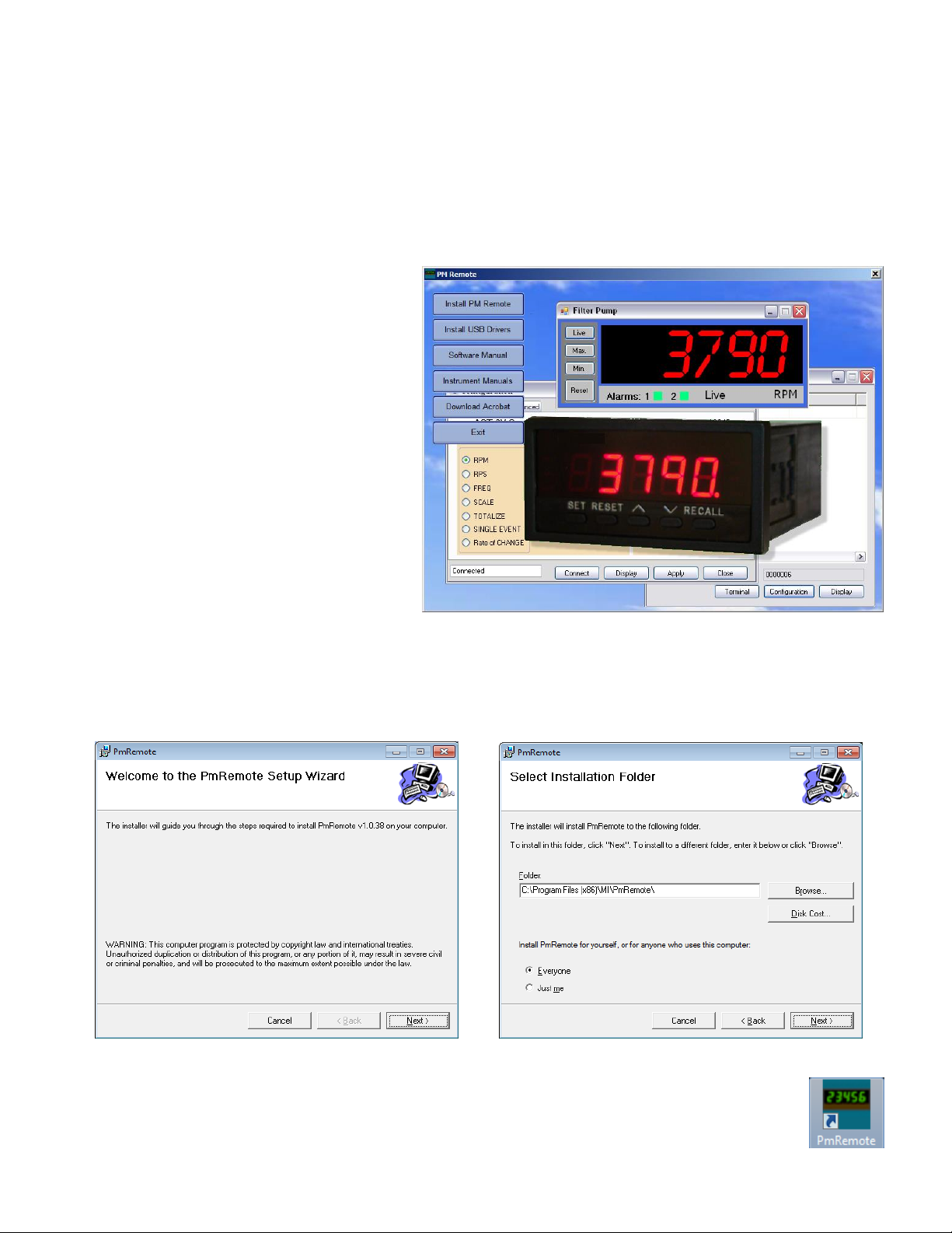
CD_Start.exe. The installation program will
launch and display the menu as shown right.
The help files are in PDF format. If
necessary, click on the “Download Acrobat”
button to install the latest version of Acrobat
Reader.
To install the main application, click the
“Install PM Remote” button. This will launch
the PM-Remote setup wizard shown below
left. Click the “Next >” button to continue to the license agreement. Accept the license agreement – “I Agree” (or
quit the installation) and click the “Next >” button to continue. You will then be asked to enter your information –
name and business. Enter the information if you wish and click the “Next >” button to continue. Now select the
installation folder – shown below right. If you wish to change the default for any reason, enter the new install
location. If you want the software to be available for any user on this computer, make sure to select “Everyone”.
Click the “Next >” button.
On the “Confirm Installation” screen, click the “Next >” button. The software will be installed.
Note: This program requires the DotNet component. If it is not found on the system it will be installed.
When completed click the “Close” button. A shortcut icon (shown right) will be placed on the desktop.
It is now necessary to install the USB drivers.
Page 2 Rev 1.08 062019
Page 3
PM-Remote User‟s Guide
1.2 Installation of USB Drivers
Note: Ensure the USB programming cable is NOT plugged in during this installation.
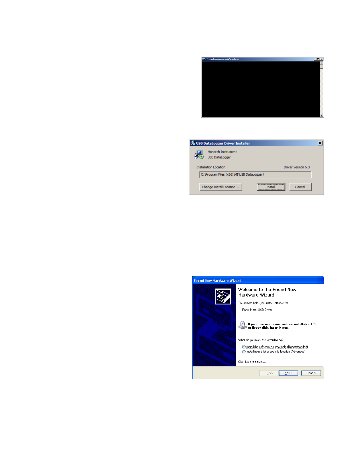
From the Install menu select “Install USB Drivers”. Because PM
Remote Software is used for multiple products that use different
USB components, two different USB Drivers will be installed. A
batch file will run and a DOS window (shown right) will remain
on the screen until both USB drivers have been installed.
The first USB driver is for products using the FTDI USB
component. This driver will automatically install without any
user interaction. Note: Files for this driver are stored in the
„PMRemote_Software file resources‟ folder in the FTDI VCP Driver directory.
The second USB driver is for products using the SiliconLab
USB component. This driver will bring up the Installer
window shown right. Note: This installer is stored in the
„PMRemote_Software file resources‟ folder in the
SiliconLab VCP Driver directory.
The default installation location will be shown, if you wish
to change it for any reason, click on Change Install
Location… and enter the new install location. Click the “Install” button. The system will be scanned and then the
driver software will be installed. Follow any instructions.
You may get the Window‟s Security or Unsigned Driver warning message – click “Install this driver software
anyway” or “Continue Anyway” and the driver software will be installed. Click “OK” once installation is complete.
The DOS window from the batch file will close once both USB drivers have been installed.
1.3 Insert USB Cable (if applicable)
For units that will be connected to the PC via USB, insert
the USB cable into the USB slot on the computer.
If this is the first time use of the USB connected product,
your computer will notify you “Found New Hardware”.
For products that use the FTDI USB component, the Found
New Hardware message will pop up in the bottom right area
of your screen. No further action is necessary.
For products that use the SiliconLabs USB component, you
will get the Found New Hardware Wizard as shown right.
Select the “Install the software automatically” option and
click the “Next >” button. Your system should find the USB
drivers installed from section 1.2. Note: The file needed by the wizard is “PanelMeterVCP.inf” which should be
found automatically.
You may get the Window‟s Logo testing or Unsigned Driver warning message – click “Install this driver software
anyway” or “Continue Anyway”. The wizard will copy the necessary files and indicate that it is done. Click the
“Finish” button. The product is now ready for use.
Page 3 Rev 1.08 062019
Page 4

PM-Remote User‟s Guide
2.0 PM-Remote Software
To start the PM-Remote software, double click the icon shown right.
In order for the software to function a remote panel meter must be plugged into the PC either via:
1) A USB port on the PC:
a. ACT-1X or F2A1X using the USB Programming Cable
b. ACT-3X with Serial Communication option using the
USB Programming Cable
c. ACT-3X or F2A3X with USB option
2) An RS-232 DB9 Cable (ACT-3X with RS-232 option)
3) An Ethernet cable (ACT-3X or F2A3X with Ethernet option)
Within PM-Remote there are two options to connect - via Serial
Port/USB or Ethernet. Choose the option that matches the interface on
the device you have. Note: The ACT-3X/F2A3X USB interface
emulates a Virtual Com Port (VCP) and should be selected as a
Serial Port.
2.1 Connection Options
There are two possible methods of connecting to remote units:
2.1.1 Serial Port
The Serial Port option is for the RS-232 connection or the
USB Virtual Com Port whereby the USB port looks like a
Serial Com Port to the PC. Select the “Serial Port” radio
button. The User needs to select the correct Com Port
from the drop down menu. You can check the correct port
using the PC Device Manager. For Windows 7: Click Start, Control Panel, Device Manager, Ports (COM &
LPT). For XP: Click Start, Control Panel, System, Hardware tab, Device Manager, Ports (COM & LPT).
The correct port will be listed as Panel Meter USB Driver.
If you know the Baud Rate select it from the drop down menu otherwise check “Auto Baud” which will
automatically determine the baud rate. You can also select a Baud rate and click the “Force Baud” button
which will set the remote unit baud rate to that selected. Finally click the “Connect” button to make the
connection. It will turn green when the connection is made.
2.1.2 Ethernet
The Ethernet connection requires that the remote unit be
connected to the Ethernet. Select the “Ethernet” radio button.
You need to set the remote unit IP Address – this is what you
set on the remote unit front panel – refer to the device user manual.
There are four modes of operation of the program: ASCII Terminal mode, Configuration mode, Real Time Display
mode, and Excel export. Select the operation mode to work with by clicking the button at the bottom of the window.
Note: Only one mode can be used at a time – except for Enable Excel which requires Display be active.
As long as the program is active a small icon will appear at the right of the task bar.
Page 4 Rev 1.08 062019
Page 5

PM-Remote User‟s Guide
COMMAND
LINE
2.2 Terminal Mode
Selecting “Terminal” from the start up window will launch the Terminal Mode Program, a serial ASCII
communication program that allows the user to send and receive ASCII strings to/from the remote unit. The list of
commands is available in the User Manual for the product. This window can be sized by dragging the edges.
The Terminal mode window is shown right with the following areas
highlighted:
2.2.1 Display Area
This area is used to display results sent from the remote
unit. When the area fills the window scrolls. The scroll bars
can be used to scroll back through data. The “Clear”
button is used to clear the display area.
2.2.2 Command List
This is a list of commands (not complete) that can be sent
to the remote unit. Double click the command to send it to
the remote unit or click it once to enter it into the command
line where it can be modified if needed and sent by
clicking the “Send” button.
2.2.3 Command Line
Commands entered here are sent to the remote unit when the “Send” button is clicked (or the enter key is
pressed).
2.3 Configuration Mode
The configuration mode is a Graphical User Interface (GUI) that allows easy set up of the remote unit. The
configuration is device dependent. After selecting a communication option click the “Configuration” button on the
startup window.
When the Configuration window opens it will attempt to connect with the remote unit automatically. To connect
manually click the “Connect” button.
The window will display the type of device
connected, its serial number and current
configuration depending on which device is
attached and its options (an example is shown
right). There are three tabs – General, Alarms
and Advanced. (Not all tabs apply to all
devices.)
To save the configuration data to the remote
unit click the “Apply” button. To view the live
display, click the “Display” button. To exit the
application, click the “Close” button. The “Help”
button will bring up this file.
Page 5 Rev 1.08 062019
Page 6

PM-Remote User‟s Guide
2.3.1 General
These are the most frequently used options that can be set by the user. Refer to the device User manual
for a full definition of the options available.
Mode of Operation – select how the unit is configured to operate. Choices are dependent on the unit type
attached. The ACT-1X, F2A1X and F2A3X will have limited CH-1 (Channel 1) Mode Selections. The
ACT-3X has both CH-1 and CH-2 modes.
To set the mode – RPM in the above example, select the radio button to the left of the desired mode as
shown.
The Scale mode has the option to enter a scale factor. The scale factor can be used to program the
display in any units the user wants. It takes an input in Hz (cycles per second) and multiplies it by the scale
factor and this is what is displayed. The scale factor can be fractional.
Note: To change the PPR (Pulses Per Revolution) used by the ACT or F2A Series, you must select the
Scale mode. Then enter the Scale Factor as determined by: Scale=60/PPR
Check the device user manual for a description of the operating modes.
Display – Allows the user to set the number of decimal points shown on the instrument display and the
display update rate (in seconds).
Analog Output – Allows the user to set the value for Full Scale and Zero output of the analog option
installed in the unit. If the option is not installed then the entry area will be grayed out and values cannot
be entered. The data is entered in display units. (eg – if the unit is displaying RPM the analog output is set
in RPM). The Zero Scale can in fact be non zero for greater resolution. For example if you have a 4 to
20mA output, the unit can be set for a zero of 1000 and a full scale value of 2000 giving a span of 1000
over the 16mA change in output.
2.3.2 Alarms
Device dependent, this tab allows the
user to set up the alarm options of the
remote unit. There is a sub tab for each
alarm. Not all devices have alarm
capability.
Setpoint – The value at which the alarm
is activated (in displayed units)
Deadband – The value added (low
alarm) or subtracted (high alarm) to the
setpoint to create a reset point. As shown
right, the alarm setpoint is 200, so the
reset point will be 180.
Alarm Type – Check High, Low or Off
Latching – If checked, the alarm will set but will not reset until a physical reset signal is received from the
front button or rear input.
Page 6 Rev 1.08 062019
Page 7

PM-Remote User‟s Guide
Lock Out – If checked, the alarm will not activate until the setpoint has been reached. (For example if the
alarm is a low alarm at 1000, the alarm will not activate on start up until the alarm setpoint has been
reached, then it will activate.)
Fail Safe – If checked, the sense of the output relays will be reversed. The relays will activate when NOT
in alarm. In the event of a power fail, the relays will drop out as if the alarm had been set.
2.3.3 Advanced
This tab is for the more advanced features. Options are device dependent. Refer to device User Manual.
Zero Time – The gate time that the unit
will use to determine an input of zero (in
seconds – 12 seconds is a low of 5 RPM).
Gate Time – The rate at which the unit will
measure input at higher speed. The Fast
time will update serial data faster at
reduced accuracy.
Input Signal Trigger – Select the sense of
the input pulse trigger.
Output Pulse - Select the sense of the
optional pulse output.
Local Live Display: - Allows the user to customize the local display (see below):
Window Header – the text string displayed on the top of the local digital display
Eng Units - Engineering Units or any text string displayed on the bottom right of the display
Note: To save these settings for future recall – press the “Apply” button
PassCode – The five number code used to prevent unauthorized setting of the remote unit via its front
panel. No code means the remote input will be unlocked.
The “Config Load” and “Config Save” buttons allow the user to load saved configurations or save the
current configuration to the local PC media.
The “Detail” button pops up a window and shows an overview of the current settings of the connected unit.
Clicking “Detail” again will close it.
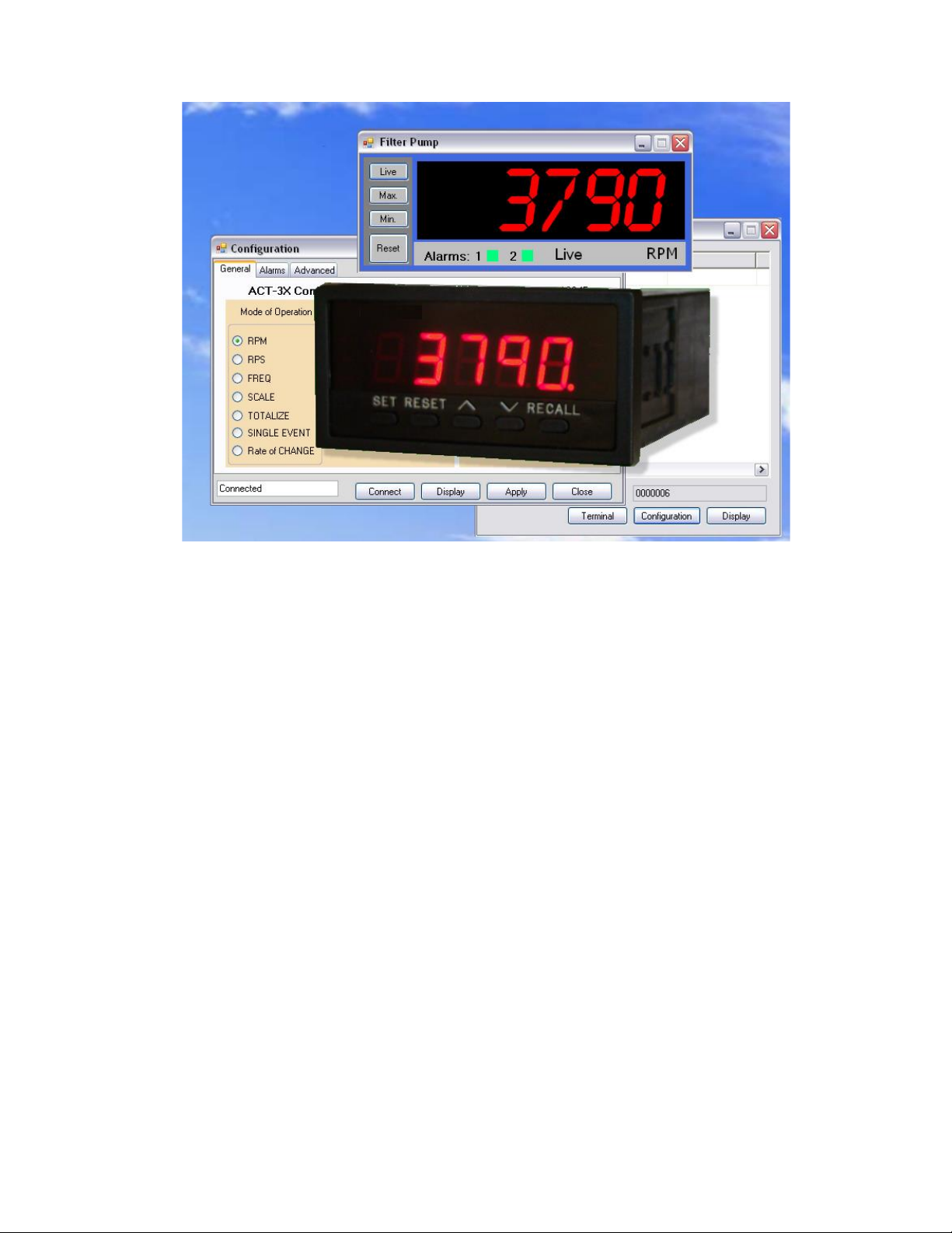
2.4 Display Mode
The display mode pops up a real time display of the remote unit
readings. The user can view live data, the maximum or
minimum (at the time the button is clicked) and alarm status –
also shown in real time.
Note that the Windows Header – “Filter Pump” and engineering
units – “RPM” in the example shown right is set in the
configuration Advanced tab – Section 2.3.3 above.
Page 7 Rev 1.08 062019
Page 8

PM-Remote User‟s Guide
There are four buttons on the left of the display:
Live Click to show live data.
Max. Click to show Maximum value.
Min. Click to show Minimum value.
Clear Click to clear maximum, minimum.
Alarm Reset Click to clear alarm.
Total Reset Click to clear totals. Only available if the channel is configured as totalize.
Along the bottom of the display are boxes that indicate status:
Alarms: A green box means the alarm is not set. A red box means the alarm is active.
Live Toggle: A green box to the left of the word “LIVE” will toggle on and off as data is updated
2.4.1 Display Configuration
The display colors can be set by the user. Right click anywhere on the display area. This will pop up the
configuration option. Select the following:
Configuration Go to the Configuration menu – Section 2.3
Background Color Choose a background color
Display Color Choose a display (segment) color
Save Colors Save Colors to PC configuration file
Click the “X” in the top right corner of the Display Window to exit.
2.5 Enable ExcelTM
Note: The Display must be running in order for the “Enable Excel” option to work. If it is not, it can be launched
by clicking the “Display” button at the startup window.
Note: You need to have Microsoft ExcelTM version 2003 or later
on your system.
Clicking the “Enable Excel” button will open up an Excel
spreadsheet and will export the “live” data to cells on the
spreadsheet in real time. The value will update as long as the
remote unit is attached and the PC display mode is active. You can
open new worksheets and use this data as you wish.
In Excel the PmRemote tab is where the data source is. It will show
“Value” - the live data, “Device ID” - the window header and “Eng
Units” – the engineering units. A live example is given in the
spreadsheet on the “Sheet1” tab. Use this data by referring to it in
cells on your own tab (eg. “=+PmRemote!A2”).
The live example can be deleted.
If you do not wish to see the digital displays you can right
click the “Display” button and select “Hide All”. This will
hide all displays. To see them again right click the
“Display” button and select “Show All”.
Note: When done, make sure to click the “Disable Excel” button to remove the driver from memory.
Page 8 Rev 1.08 062019
Page 9

PM-Remote User‟s Guide
2.6 Record
The record mode pops up a record window to allow the user to
record data.
Click the Setup button to allow the user choose the recording
rate/interval and where to record the data. After recording is
stopped, the recorded data can be viewed by opening the saved
file.
If the connected device is THProbe, the data can be saved as
Track-It format and can be viewed by our Track-It Software.
Page 9 Rev 1.08 062019
 Loading...