

Page 1
15 Columbia Drive
Amherst, NH 03031 USA
Phone: (603) 883-3390
Fax: (603) 886-3300
E-mail: support@monarchinstrument.com
Website: www.monarchinstrument.com
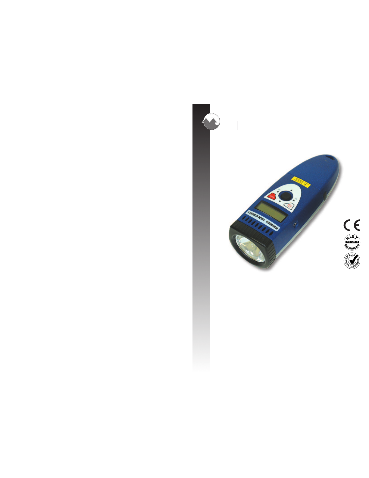
PALM STROBE x
Pocket-Size, Portable Stroboscope
Stroboscope Portable de Poche
Estroboscopio Portatil de Bolsillo
MONARCH INSTRUMENT
Instruction Manual
Patented
Breveté
Patento Estroboscopio
Impreso en los EEUU.
El derecho de autor 2010 Monarch Instrument, reservó bien
1071-4205-S10R
1071-4205-313R - 1210
Page 2
Safeguards and Precautions
1. Read and follow all instructions in this manual carefully, and retain this manual for
future reference.
2. Do not use this instrument in any manner inconsistent with these operating
instructions or under any conditions that exceed the environmental specifications
stated.
3. Certain strobe frequencies can trigger epileptic seizures in those prone to that
type of attack.
4. User should not stare directly at the light source.
5. Prolonged exposure to the light can cause headaches in some people.
6. Objects viewed with this product may appear to be stationary when in fact they
are moving at high speeds. Always keep a safe distance from moving machinery
and do no touch the target.
7. There are lethal voltages present inside this product. Refer to the section on
Lamp Replacement before attempting to open this product.
8. Do not allow liquids or metallic objects to enter the ventilation holes on the
stroboscope as this may cause permanent damage and void the warranty.
9. Do not allow cables extending from the unit to come into contact with rotating
machinery, as serious damage to the equipment, or severe personal injury or
death may occur as a result.
10. This instrument may not be safe for use in certain hazardous environments, and
serious personal injury or death could occur as a result of improper use. Please
refer to you facility’s safety program for proper precautions.
11. This product contains Nickel Metal Hydride batteries which must be disposed of
in accordance with Federal, State and Local Regulations. Do not incinerate.
Batteries should be shipped to a reclamation facility for recovery of the metal and
plastic components as the proper method of waste management. Refer to section
7.3 of this manual, and contact your distributor for appropriate product return
procedures.
12. This instrument is not user serviceable. For technical assistance, contact the
sales organization from which you purchased the product or Monarch Instrument
directly.
In order to comply with EU Directive 2002/96/EC on Waste Electrical
and Electronic Equipment (WEEE): This product may contain material
which could be hazardous to human health and the environment. DO
NOT DISPOSE of this product as unsorted municipal waste. This product
needs to be RECYCLED in accordance with local regulations, contact
your local authorities for more information. This product may be returnable
to your distributor for recycling - contact the distributor for details.
Esta página intencionalmente blanco de izquierda.
Page 3

1.0 SPECIFICATIONS ................................................................................... E-1
2.0 OVERVIEW ............................................................................................ E-2
2.1 Display Panel ................................................................................ E-3
3.0 PREPARATION FOR USE ....................................................................... E-3
3.1 Power ............................................................................................ E-3
3.2 Input / Output Connections ............................................................ E-3
4.0 OPERATION ............................................................................................ E-4
4.1 Internal Mode - Standard Strobe Operation ..................................... E-4
4.2 External Input Mode ....................................................................... E-5
4.3 Tach Mode (No Flash) - External Input Required ............................ E-6
5.0 USING THE STROBOSCOPE TO MEASURE RPM ................................ E-6
6.0 LAMP REPLACEMENT ........................................................................... E-7
7.0 BATTERY PACK...................................................................................... E-8
7.1 Low Battery Indication .................................................................... E-9
7.2 Charging the Battery Pack ............................................................. E-9
7.3 Battery Disposal .......................................................................... E-10
8.0 OPTIONS AND ACCESSORIES ............................................................. E-11
TABLE OF CONTENTS
TABLE OF CONTENTS
Monarch Instrument’s Limited Warranty applies. See
www.monarchinstrument.com for details.
Warranty Registration and Extended Warranty coverage available online at
www.monarchinstrument.com.
8.0 OPCIONES Y ACCESORIOS
PSx Batería NiMH adicional Paquete azul de Batería (uno es suministrado con la luz
Estroboscópica)
SPSR-115/230 El Sensor de ser-accionó para TTL, la entrada del disparador o la operación
del modo de Tacómetro; incluye ROS-P sensor óptico con 8 cable de pie,
115/230 Vac recharger Universal y 12 pulgadas de cinta reflectora.
PS Cable de Entrada Pulso Cable de entrada, 6 pie {1.8 M}, 1/8 pulgada {3.5 mm} tapón estéreo
al conector masculino de BNC. Utilizado con el Sensor de ser-accionó.
PS Cable de Salida El Cable de la Producción de pulso, 6 pie {1.8 M}, 1/8 pulgada {3.5 mm}
mono tapón al conector masculino de BNC. Utilizado con Recaudadores de
Datos de Vibración.
PSC-2U Recharger universal (Juego) para el Paquete de Batería de PSx - Universal
100 a 230 recharger de Vac con tapones variados de adaptador (uno es
suministrado con la luz Estroboscópica cuando ordenado como 115/230)
CC-9 Cerrar con picaporte que lleva el caso para PALM STROBE x con la
provision para accesorios
PS Holster La funda que lleva el caso para la PALM STROBE x y reserva Paquete de
Batería que prende el lazo de cintura
L-1905 PALM STROBE x reserva lámparas (flashtubes), paquete gemelo
S-11
Page 4
E-1
1.0 SPECIFICATIONS
Internal Mode:
Flash Range 100 - 12,500 FPM (Flashes per Minute)
Flash Rate Accuracy The greater of ±0.5 FPM or ±0.01% of reading
Flash Rate Resolution (Setting) 0.1 FPM
Display Update Rate Continuous
External/Tachometer Mode:
Flash Range and Display 5.0 to 12,500 FPM - External flash rates to 0 are acceptable
Tachometer Measurements 5 to 250,000 RPM - No flash
Accuracy The greater of ±0.1 FPM or ±0.01% of reading
Display Update Rate 1 second typical
Trigger to Flash Delay < 5 µsec
External Input 0 to 5 volt TTL Compatible (12V pk max)
1 µsec min pulse width, Positive edge triggered
Time Base Stable Crystal Oscillator
Display 6-digit alphanumeric backlit LCD display with 0.3 inch [7.62 mm] high digits
Indicators Low Battery, On Target Indicator, Locked On, External Mode, Tachometer
Mode, ÷2 ×2
Adjustment Four Quadrant Tuner Button with decade select for flash rate up or down,
multiply by 2 and divide by 2
Memory Saves eight programmable flash rates and last flash rate at power down
Output Pulse 350 µsec positive pulse, 5 Vdc typical
Power Removable 6 Vdc Rechargeable Battery Pack with Integral Electronics Charge
Control for rechargers (PSC-2U Recharger: 9 Vdc @ 500mA)
Light Power 150 mJ/Flash up to 3000 FPM, 7.9 Watts @ 6000 FPM
Flash Duration 10 - 30 microseconds typical
Run Time 2 hours at 1800 FPM and 1 hour at 6000 FPM typical with fully charged
batteries
Charge Time about 4 hours
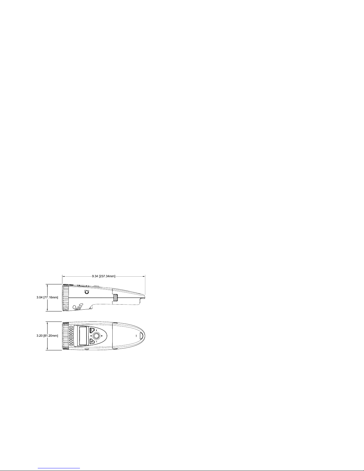
Weight 1.2 lbs [544 g] including Battery Pack
Figure 1 Dimensions in Inches [mm]
7.2 Cargar el Paquete de Batería
El Paquete de la Batería puede ser recargado en tiempo. Usted no necesita esperar hasta que la
condición baja de batería sea indicada. El Paquete de la Batería no necesita para estar en la luz
Estroboscópica para cargar.
Para cargar el Paquete de Batería:
1. Cerciórese la luz Estroboscópica está apagado o quita el Paquete de Batería de la luz
Estroboscópica.
2. Tape el cable de recharger en el enchufe de recharger de batería en el Paquete de Batería (vea
la figura 2 para la ubicación).
3. Tape el recharger en una salida de pared de red de C.A.
LA NOTA: Cuando se usa el recharger Universal, la marca segura el tapón correcto
del adaptador es metido en el recharger antes de tapar el recharger en la
salida de pared.
El CUIDADO: El uso de rechargers de otra manera que el uno suministrado (PSC-2U)
pueden dañar el estroboscopio y vaciar la garantía.
El módulo de la batería contiene red de circuitos para controlar el cambio. El ámbar DIRIGIDO
parpadea constante indicar que la batería es cargada. El DIRIGIDO girará el ámbar sólido como
carga completa cercano. Una vez que la carga es completada, las vueltas DIRIGIDAS sólido
verde y el recharger chorrearán un poco la carga la batería. El Paquete de la Batería puede ser
utilizado en este punto.
LA NOTA: El tiempo total de la carga es típicamente acerca de 4-5 horas. El Paquete
de la Batería puede ser dejado en chorrea un poco la carga indefinidamente.
El DIRIGIDO indica también ese cargar ha parado debido a un problema. El DIRIGIDO parpadeará
5,6,7 o 8 corto rojo parpadea y entonces un largo verde parpadea para indicar lo siguiente: 5 = sobre
el voltaje, 6 = sobre la corriente, 7 = demasiado caliente, y 8 = demasiado frío.
7.3 Disposición de Batería
Antes de deshacer del Paquete de Batería, el usuario debe quitar las baterías de Metal de Níquel
Hydride. Para hacer esto, quitar los cuatro tornillos en el bajo el lado del Paquete de Batería y
separar las mitades del caso, exponiendo la batería. Quite los cables de la cinta de batería y lugar
sobre las terminales de batería para prevenirlos de shorting. La batería debe ser mandada a un
reciclaje central o vuelto a la fábrica. El resto de las partes ahora puede ser deshecho de.
S-10
Page 5
2.0 OVERVIEW
The PALM STROBE x is a sophisticated stroboscope with many features, yet remains simple to
operate. It is a pocket-size, lightweight, industrial strength, single-handed operation instrument that
fits in the palm of your hand. A four Quadrant Tuner Button adjusts the flash rate, and provides
multiply or divide by 2 functions. A large, bright, backlit, 6-digit alphanumeric LCD display shows
the flash rate and mode of operation. The Strobe can store and recall eight programmable flash rate
settings and the last used setting in non-volatile memory, so that the unit “remembers” all the flash
rates when the power is turned off.
The Strobe has a removable, rechargeable Battery Pack which provides up to 2 hours of continuous
use depending on the flash rate. This Battery Pack clips in and out with no tools required. An
optional second Battery Pack allows for longer operation in the field. A ¼-20 UNC thread bushing
on the underside of the Strobe allows for tripod mounting. The Strobe locks “ON” for hands free
operation.
The Input/Output phone jack will accept an external input up to the maximum FPM and can be used
with an external Self-Powered Sensor to measure RPM. The Input/Output phone jack will also
provide TTL output pulses for each flash.
E-2
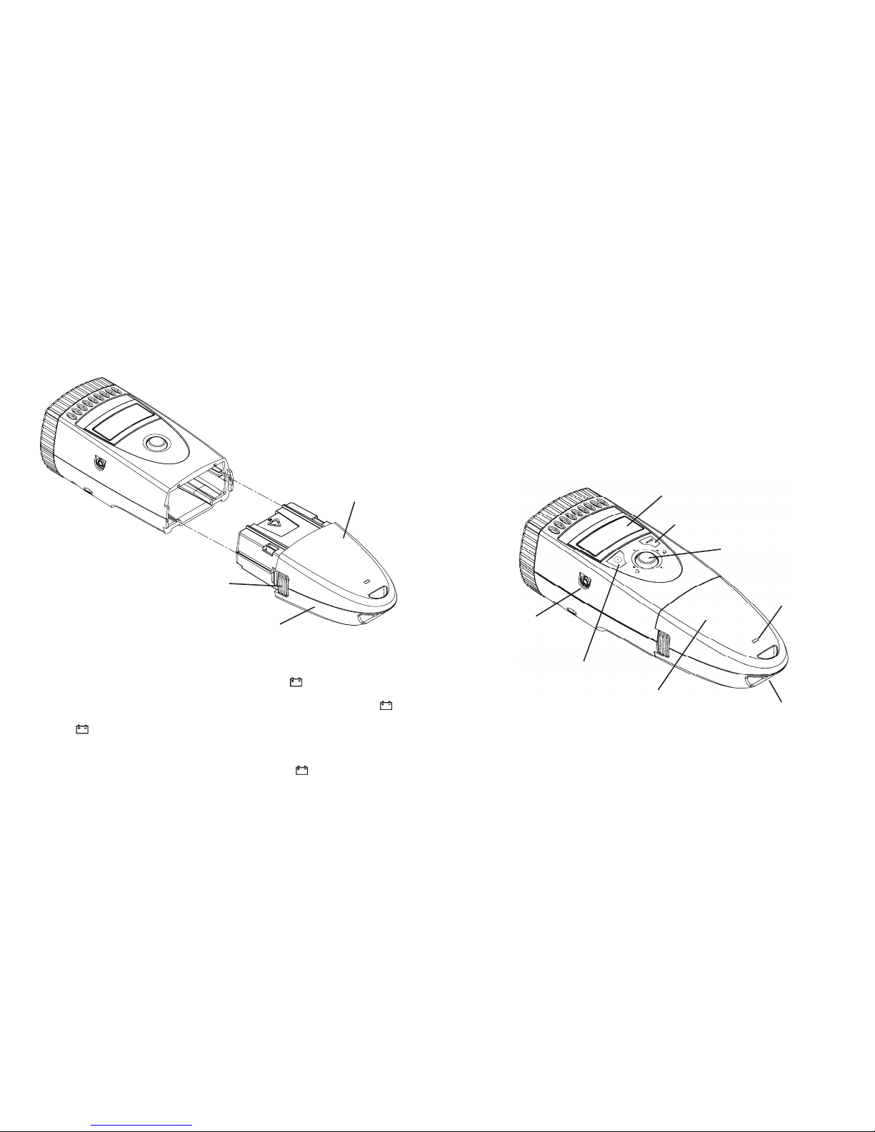
Input/Output
Phone Jack
Battery
Charge
Indicator
Battery
Recharger
Socket
Figure 2 PALM STROBE x
Tuning Button
This product protected by U.S.A. Patents D492,805 and 6,945,666.
LCD Display
Removable
Battery Pack
Power Button
Mode Button
El Paquete de la Batería puede ser quitado apretando los dos picaportes a ambos lados de la unidad
mientras tirando suavemente el Paquete de Batería exterior (vea la figura 8). Para instalar el Paquete
de Batería, deslicelo en la luz Estroboscópica hasta que usted oiga que los picaportes del lado
comprometen y cierran. Empareje la cima y el fondo colora al meter el Paquete de Batería en la luz
Estroboscópica. El Paquete de la Batería es adaptado para que no pueda ser metido en la luz
estroboscópica al revés.
El CUIDADO: Las terminales en el Paquete de Batería son recessed. HAGA NO
BREVEMENTE ESTAS CONEXIONES. Hay un fusible interno no-utilizable
de resettable para la protección.
La Figura 8 La Eliminación del Paquete de la Batería / la Instalación
7.1 Indicación Baja de Batería
Cuándo las baterías son bajas, el icono Bajo de Batería ( ) es demostrado. La luz
Estroboscópica puede ser utilizada todavía para un tiempo corto. Cuándo la carga de batería es
agotada aún más, la luz Estroboscópica parará destellar, el icono Bajo de Batería ( ) será
demostrado, y entonces la luz Estroboscópica apagará completamente. Cuándo el icono Bajo de
Batería ( ) es demostrado, las necesidades de Paquete de Batería para ser recargadas (vea la
sección 7.2).
La NOTA: Si las baterías le es descargadas no podrá correr la unidad. La unidad no
puede empezar todo, ni el icono Bajo de Batería ( ) pueden ser demostrados
y entonces la luz Estroboscópica apagará. Recargue el Paquete de Batería o
lo reemplaza con una unidad completamente cargada.
S-9
La prensa
ambos lado
para liberar
La NOTA: La cima del igual y el
caso del fondo coloran
al deslizar Paquete de
Batería en la luz
Estroboscópica.
La cima
es azul
El fondo es gris
Page 6
E-3
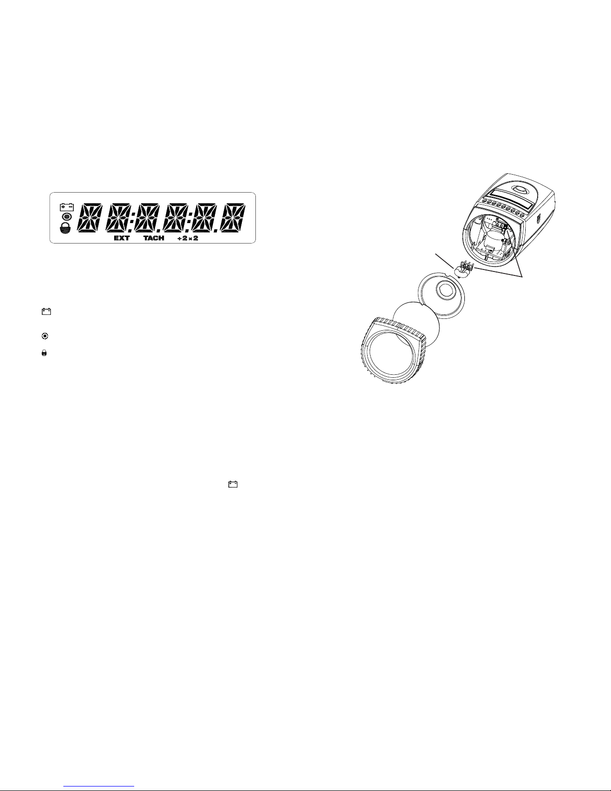
2.1 Display Panel
The display panel consists of a backlit, liquid crystal display with six alphanumeric digits
which indicate modes, flash rates, etc. (see Figure 3).
Other icons or messages in the display indicate the following:
Displayed when the battery is getting low. There is protection circuitry in the
unit that will prevent the battery from being over discharged or prevent the unit
from being operated with a low battery.
On Target Indicator for Tachometer Mode and Remote Sensor in External Input
Mode
Shown on the display to indicate that the Strobe is locked on.
EXT Shown on the display when the Strobe is in the External Input Mode.
TACH Shown on the display when the Strobe is in the Tachometer Mode.
÷2 ×2 When this icon is shown on the display, rocking the tuning button to the left will
divide the current flash rate by two and rocking the tuning button to the right will
multiply the current flash rate by two.
3.0 PREPARATION FOR USE
PALM STROBE x may be hand held or mounted on a tripod or other user supplied bracket using the
¼-20 UNC bushing in the base of the unit.
3.1 Power
PALM STROBE x has a removable Nickel Metal Hydride Battery Pack that clips in and out of
the main strobe housing. The Battery Pack should be charged before use (see section 7.0). The
Strobe has a protection feature that prevents the Strobe from operating if the battery voltage is
low. This condition is indicated by no flash and the Low Battery icon ( ) will be displayed
(see section 7.1). At this time the Battery Pack must be recharged or exchanged for a fully
charged Battery Pack. The actual operating time of the stroboscope depends on the flash rate
and duty cycle of operation. Slower flash rates increase the operating time.
3.2 Input / Output Connections
PALM STROBE x has a TTL Input/Output phone jack on the side of the stroboscope. This
jack accepts a 1/8 inch (3.5 mm) stereo phone plug and can be used for external triggering or
synchronization of the stroboscope or for providing a TTL pulse output, synchronous with the
flash.
Figure 3 Display Panel
S-8
La Figura 7 Reemplazo de Lámpara
Vuelva a instalar el reflector y entonces posicione el lente anterior en el igualar del lugar los cortes en
el lente con las dos pequeñas etiquetas en la envoltura para prevenir la rotación de lente (vea la figura
7). Estire los parachoques de caucho sobre la cima y mitades de caso de fondo para conservar el
reflector y lente anterior.
7.0 PAQUETE DE BATERÍA
La PALMSTROBE x es quedado con NiMH recargable (Metal de Níquel Hydride) baterías. Estas
baterías contienen menos metales tóxicos que NiCD (Cadmio de Níquel) y son clasificados actualmente
“ambientalmente amistoso”. Ellos tienen también 30% más capacidad que baterías de NiCD del
mismo tamaño.
Como NiCDs, baterías de NiMH son propenso a la auto-descarga - 10 a 15% de la carga son
perdidos en las primeras 24 horas entonces continúa a razón de 0,5 a 1% por día. Para el desempeño
máximo, cargue las baterías apenas antes del uso.
Cuándo no en uso, las baterías deben ser cargadas por lo menos cada tres meses, de otro modo la
capacidad de batería será reducida o las baterías pueden llegar a ser inutilizables.
Cargue las baterías utilizan antes y permiten 3-5 ciclos de cargar y descargar para baterías
para alcanzar la capacidad repleta.
El cerco contiene la electrónica del control a carga sin peligro y apropiadamente las baterías. Nunca
quite las baterías del cerco y la tentativa para cargar externamente. Siempre utilice el corcel
suministrado (PSC-2U).
Empareje los
puntos rojos para
la polaridad
L-1905 Lámpara
Page 7
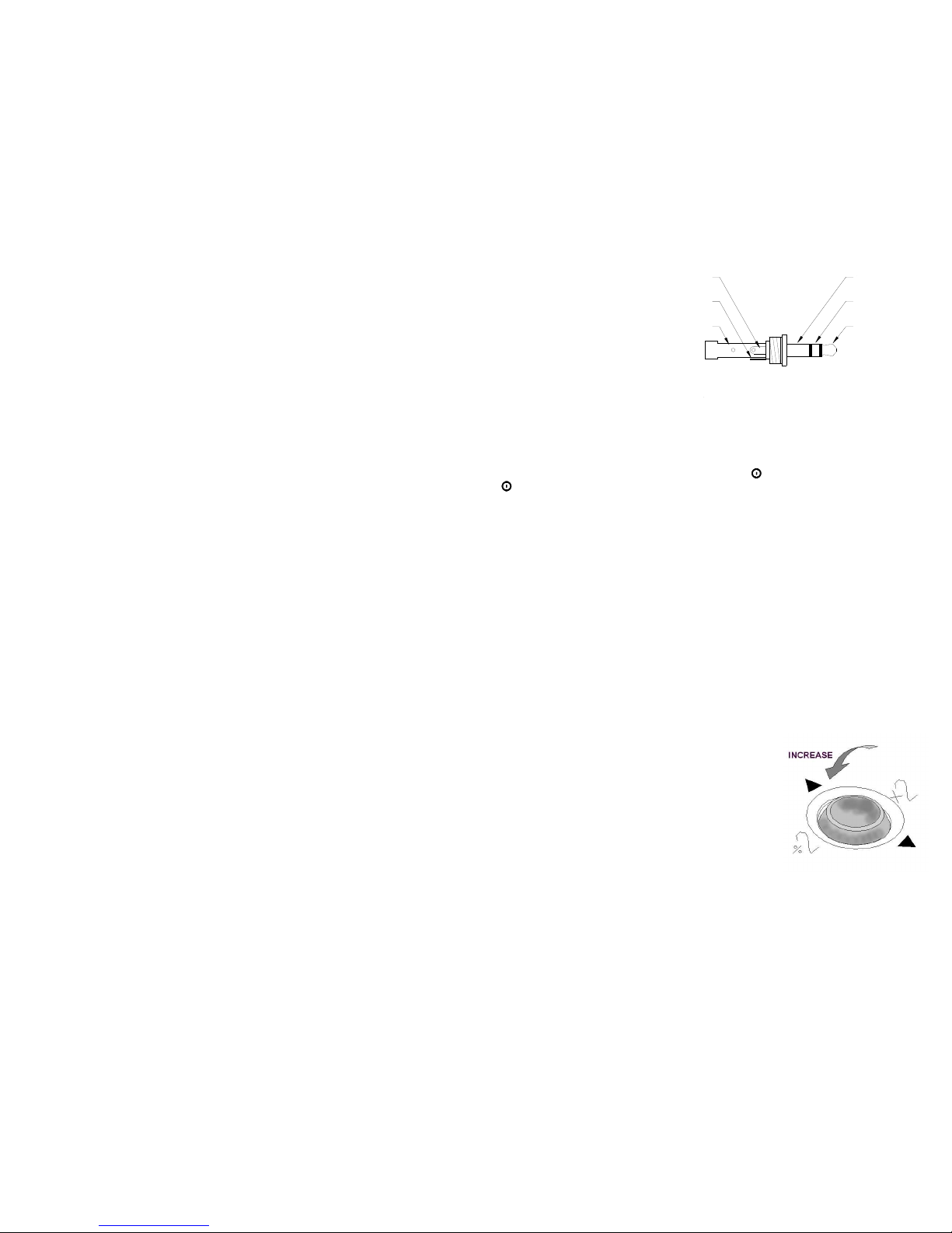
Figure 5 Tuning button
The jack’s outer
connection (barrel) is
common, the inner or
center connection is the
signal, and the tip is the
pulse output (see Figure
4). The input and output
are TTL compatible.
With no external input the
Strobe provides a TTL
compatible pulse output from the Strobe’s internal oscillator. If an external input is applied, the
output pulse mimics the input pulse. The jack has no voltage output for a sensor.
4.0 OPERATION
To turn on the stroboscope, press and release the On/Off ( ) button. Press and release the On/Off
( ) button again to turn the Strobe off.
When the Strobe is powered up, it will begin flashing immediately at the last internal flash rate
displayed. The last digit changed will flash for 5 seconds allowing the digit to be changed again. Rock
the tuning button up or down to change the flashing digit. Rock the tuning button left or right to
select a different digit to change.
The flash rate is displayed on the LCD display in flashes per minute, which typically is the same
as RPM.
The PALM STROBE x has three primary operating modes (Internal, External Input and Tach) and
three functions (÷2 ×2, Recall and Store) that are adjusted by the MODE button. By default, the
Strobe powers up in the Internal Mode. Pressing the MODE button will change the mode/function
in the following order: ÷2 ×2, Recall, Store, External, Tach, Internal. The ÷2 ×2, Recall and Store
functions are only applicable to the Internal Mode.
In the Internal Mode, the tuner button adjusts the flash rate from the minimum to the maximum
number of Flashes Per Minute (FPM or RPM). In the External Input Mode, an external signal from
another strobe or a remote self-powered sensor is used to trigger the flash and the tuner button has
no effect. In the Tach Mode the unit will not flash, but will display the input from an external (self-
powered) sensor as RPM up to 250,000 RPM.
4.1 Internal Mode - Standard Strobe Operation
In the Internal Mode the stroboscope generates it’s own
frequency variable speed signals and functions like a typical
stroboscope. This is the default start up mode.
The rubber tuning button functions as a joystick. The
tuning button is sensitive in four directions. Place your
thumb on the button and use a rocking motion (forward,
back, or side-to-side) to control it (see Figure 5). It is
possible to adjust the Strobe in 0.1 FPM increments.
E-4
Signal Output
Common
(GND)
Common
(GND)
Signal Input
Signal Output
Figure 4 Input/Output Connector Detail
Signal Input
S-7
Si un Sensor Optico Remoto o Sensor Magnético son utilizados para presentir un pulso por la
revolución (el Modo de Entrada Externo), la lectura de salida demostrará directamente en RPM
(FPM) sin cualquier ajuste requerido.
En casos cuando usted puede cerrar el dispositivo e instalar un pedazo de cinta reflectora, entonces
un tacómetro óptico es más fácil de utilizar para la medida de RPM. Puede utilizar el PALM
STROBE x con un sensor externo como un tacómetro óptico. Estroboscopios deben ser utilizados
cuando usted no puede cerrar el dispositivo. El ojo humano no es engañado fácilmente a ver una
imagen parada por un estroboscopio cuando la tasa rápida es más lenta que 300 FPM. Por lo tanto,
estroboscopios son casi igual imposibles utilizar debajo de 300 FPM para la inspección o para medir
RPM.
6.0 REEMPLAZO DE LÁMPARA
La ADVERTENCIA: Antes procurar para quitar la lámpara, la marca segura el
estroboscopio es apagado y quita el Paquete de Batería (vea la
sección 7.0). Permita la lámpara para refrescar esperar por lo
menos 5 minutos.
El estroboscopio es diseñado para descargar los voltajes altos internos dentro de 30 segundos. Sin
embargo, el cuidado debe ser ejercitado al reemplazar la lámpara.
Para cambiar la lámpara es necesario para sólo quitar el lente anterior, que es contenido el lugar por
los parachoques de caucho. Curiosee los parachoques de caucho del fin de la unidad. El reflector es
contenido el lugar por el lente anterior y hace como afloja, pero no es necesario para quitar el reflector.
Tenga la lámpara con una tela entre su forefingir y el pulgar y lo mece apoya y adelante suavemente
al sacando. No procure girar la lámpara. La lámpara es socketed y saldrá fácilmente cuando tirado
derecho fuera.
La ADVERTENCIA: No toque la nueva lámpara con dedos descubiertos.
Las lámparas son polarizadas y deben ser puestas en el enchufe que empareja la polaridad. Utilizar
una hilas libertan tela para tener la lámpara, el igual arriba el punto rojo en el tapón con el punto rojo
en el enchufe y mecer suavemente la lámpara de aquí para allá al empujar en lugar (vea la figura 7).
Cerciórese la lámpara está en recto y centrado en el hoyo de reflector.
Page 8
E-5
To change the flash rate:
1. Press the tuning button. The last digit changed will begin blinking.
2. Rock the tuning button to the left or right to select which digit to change. The digit blinking
is the one to be changed.
3. Rock the tuning button up or down to increase or decrease the value of the blinking digit.
The digit will stop blinking after 5 blinks and the Strobe will continue to flash at the new
flash rate.
To multiply or divide the current flash rate by 2:
1. Press the MODE button once. The ÷2 ×2 icon will be displayed.
2. Rock the tuning button to the left for ÷2 or right for ×2. (Rocking the tuning button up or
down while in the ÷2 ×2 Mode will have no effect.)
3. Repeat steps 1 and 2 each time you want to multiply or divide the flash rate.
NOTE: If a multiply or divide operation will exceed the limits of the unit, upper limit or lower
limit, the display will indicate OVER or UNDER and no change will be made to the
flash rate.
To select a flash rate from a Preset (memory) location:
1. Press the MODE button once. The ÷2 ×2 icon will be displayed.
2. Press the MODE button again (without pressing the rubber tuning button in between).
“RECALL” will be displayed.
3. Rock the tuning button up or down to select a preset flash rate. The display will show “R
MEMX”, where X=the present location (1-8), and then display the flash rate saved in that
location and begin flashing at the specified flash rate with each press of the button.
4. Press the MODE button to return to the Internal Mode using the selected flash rate.
To store the current flash rate in a Preset (memory) location:
1. Press the MODE button once. The ÷2 ×2 icon will be displayed.
2. Press the MODE button a second time (without pressing the rubber tuning button in
between). “RECALL” will be displayed.
3. Press the MODE button again (without pressing the rubber tuning button in between).
“STORE” will be displayed.
4. Rock the tuning button up or down to select the location in which to store the current flash
rate. The display will show “S MEMX”, where X=the present location (1-8), and then
display the flash rate saved in that location.
5. Once you have selected a preset location to overwrite, press the MODE button to save the
current flash rate in that location. “SAVING” will be displayed and then you will return to
the Internal Mode.
4.2 External Input Mode
Press the MODE button (without pressing the tuning button in between) until the EXT icon is
displayed. An external input is required (TTL compatible source from a self-powered sensor).
In the External Input Mode there are no flash rate adjustments the user can make. The flash
rate is triggered by the TTL input signal. This mode is used to synchronize the flash to an
external event (for example, from an optical sensor) to stop or freeze motion for timing studies
or balancing machines. The flash will be triggered on the rising edge of the external input pulse.
The maximum input is 12,500 FPM, above which the Strobe will no longer flash.
4.3 Modo del Tacómetro (Ningún Destello) - La Entrada Externa Requirio
Apriete el botón del MODO (sin apretar el botón de la sintonía de en medio) hasta que el icono
de TACH sea demostrado. En el Modo de Tacómetro que la unidad leera la señal de la entrada
externa (sensor de ser-accionó) y demostrara la lectura en el despliegue de VCL, sin asignar
destellar la lámpara. La luz Estroboscópica puede leer hasta 250,000 RPM en este modo.
5.0 UTILIZAR EL ESTROBOSCOPIO PARA MEDIR RPM
El uso primario para un estroboscopio es de parar el movimiento para propósitos diagnósticos de
inspección. Sin embargo el estroboscopio puede ser utilizado para medir debe ser visible para el al
360° de la rotación (por ejemplo. El fin de un túnel). Segundo, el objeto debe tener alguna parte
extraordinaria en ello, como un cerrojo, la manera o la imperfección claves para utilizar como un
punto de referencia. Si el objeto para ser visto es perfectamente simétrico, entonces el usuario
necesita marcar el objeto con un pedazo de cinta o pintura en una sola ubicación para ser utilizado
como un punto de referencia. Mire sólo en el punto de referencia.
Si la velocidad de la rotación está dentro de la gama del estroboscopio, el comienzo en la tasa más alta
del destello y ajusta la tasa rápida hacia abajo. En algún punto usted parará el movimiento con sólo
un solo punto de referencia del objeto en la vista. Note que en una tasa rápida dos veces ese tha la
velocidad verdadera de la imagen usted verá dos imágenes (puntos de referencia). Cuando usted se
acerca la velocidad correcta usted puede ver tres, cuatro o más imágenes en armonía de la velocidad
verdadera. La SOLA primera imagen que usted ve es la velocidad verdadera. Para confirmar la
velocidad verdadera, notar la lectura y ajustar el estroboscopio a exactamente media esta lectura, o
apretar apenas el +2 botón. Usted otra vez debe ver una sola imagen (que puede ser fase cambiada con
respecto a la primera imagen vista).
Por ejemplo, al ver un túnel con una sola manera clave usted verá una imagen inmóvil de la manera
clave en la velocidad verdadera y en 1/2, 1/3, 1/4, etc., de la velocidad verdadera. Usted verá 2
imágenes de la manera clave en 2 veces la velocidad verdadera, 3 manera clave en 3 veces etc. El
Destello Por Minuto (FPM) iguala las Revoluciones de túneles Por Minuto (RPM) en la tasa
más alta del destello que da sólo una imagen inmóvil de la llave lejos.
La Figura 6 Se opone girando en 3000 RPM
Si la velocidad está fuera de la gama repleta de la escala del estroboscopio (14.000 FPM), puede ser
medido utilizando el método del cálculo de armonía y multipoint. La estrella en la tasa más alta del
destello y ajusta la tasa rápida hacia abajo. Usted encontrará múltiples imágenes tan están enterado
de éstos. Note la tasa rápida de la SOLA primera imagen que usted encuentra, llama esta velocidad
“A”. Continúe disminuir la tasa rápida hasta que usted encuentre una SOLA segunda imagen. Note
esta velocidad como “B”. Continúe disminuir la velocidad hasta que usted alcance un thrid SOLA
imagen en la velocidad “C”.
Para un dos calculo del punto que la velocidad verdadera es dada por: RPM = AB/(A-B)
Para un tres calculo de punto: RPM = 2XY(X+Y)/(X-Y)2 donde X = (A-B) y Y = (B-C)
S-6
La imagen parada 1/4 tiempos ½ tiempos 1 tiempo 2 tiempos 3 tiempos 4 tiempos
Destella la Tasa (FPM) 750 1500 3000 6000 9000 12000
Page 9

4.3 Tach Mode (No Flash) – External Input Required
Press the MODE button (without pressing the tuning button in between) until the TACH icon
is displayed. In the Tachometer Mode the unit will read the signal from the external input
(self-powered sensor) and display the reading on the LCD display, without flashing the lamp.
The Strobe can read up to 250,000 RPM in this mode.
5.0 USING THE STROBOSCOPE TO MEASURE RPM
The primary use for a stroboscope is to stop motion for diagnostic inspection purposes. However,
the stroboscope can also be used to measure speed. In order to do this, several factors need to be
considered. First, the object being measured should be visible for all 360° of rotation (e.g. the end of
a shaft). Second, the object should have some unique part on it, like a bolt, key way or imperfection
to use as a reference point. If the object being viewed is perfectly symmetrical, then the user needs
to mark the object with a piece of tape or paint in a single location, while the object is stationary, to
be used as a reference point. Look only at the reference point.
If the speed of rotation is within the range of the stroboscope, start at the highest flash rate and adjust
the flash rate down. At some point you will stop the motion with only a single reference point of the
object in view. Note that at a flash rate twice the actual speed of the image you will see two images
(reference points). As you approach the correct speed you may see three, four or more images at
harmonics of the actual speed. The first SINGLE image you see is the true speed. To confirm the
true speed, note the reading and adjust the stroboscope to exactly half this reading, or just press the
left of the joystick button for the ÷2 function. You should again see a single image (which may be
phase shifted with respect to the first image seen).
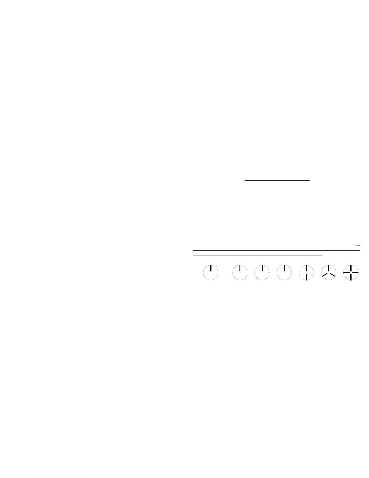
For example, when viewing a shaft with a single key way, you will see one stationary image of the
key way at the actual speed and at 1/2,1/3,1/4, etc, of the actual speed. You will see 2 images of the
key way at 2 times the actual speed, 3 key way images at 3 times, etc. (see Figure 6). The Flash Per
Minute (FPM) equals the shaft’s Revolutions Per Minute (RPM) at the highest flash rate
that gives only one stationary image of the key way.
Figure 6 Object Rotating at 3000 RPM
If the speed is outside the full scale range of the stroboscope (12,500 FPM), it can be measured using
the method of harmonics and multipoint calculation. Start at the highest flash rate and adjust the
flash rate down. Be aware that you will encounter multiple images. Note the flash rate of the first
SINGLE image you encounter, and call this speed “A”. Continue decreasing the flash rate until you
encounter a second SINGLE image, and note this speed as “B”. Continue decreasing the speed until
you reach a third SINGLE image at speed “C”.
For a two point calculation the actual speed is given by: RPM = AB/(A-B)
For a three point calculation: RPM = 2XY(X+Y)/(X-Y)2 where
X = (A-B) and
Y = (B-C)
E-6
Stopped Image 1/4 times 1/2 times 1 time 2 times 3 times 4 times
Flash Rate (FPM) 750 1500 3000 6000 9000 12000
S-5
Para cambiar la tasa rápida:
1. Apriete el botón de la sintonía. El ultimo dígito cambiado empezara parpadear.
2. Meza el botón de la sintonía a la izquierda o el derecho de escoger cual dígito para cambiar.
El parpadear del dígito es el uno ser cambiado.
3. Meza el botón de la sintonía arriba o para aumentar hacia abajo o para disminuir el valor del
dígito que parpadea. El dígito parara parpadear despues de que 5 parpadeen y el
estroboscopio continuara destellar como la nueva tasa rápida.
Para multiplicar o divider el destello actual por 2:
1. Apriete el botón del MODO una vez. El +2 icono x2 será demostrado.
2. Meza el botón dela sintonía a la izquierda paea +2 o el derecho para x2 (Meciendo el botón
de la sintonía arriba o hacia abajo mientras en el +2 x2 Modo no tendra efecto).
3. Repita los pasos 1 y 2 cada vez usted quiera multiplicar o divider la tasa rápida.
LA NOTA: Si uno multiplica o divide la operación excedera los límites de la
unidad, el límite superior o el límite más bajo, el despliegue indicara
SOBRE o BAJO y ningun cambio será hecho a la tasa rápida.
Para escoger una tasa rápida de un Presente (la memoria) la ubicación:
1. Apriete el botón del MODO una vez. El + 2 x 2 icono será demostrado.
2. Aprieta el botón MODO otra vez (sin apretar el caucho de la sintonía en medio).
“RECUERDE” será demostrado.
3. Meza el botón de la sintonía arriba o para escoger hacia abajo un fijo la tasa rápida. El
despliegue mostrara “MEMX R”, donde X = la ubicación presente (1-8), y entonces
demostrara la tasa rápida salvada en esa ubicación y empieza destellar en la tasa especificada
del destello con cada prensa del botón .
4. Apriete el botón del MODO de volver al Modo Interno que utilize la tasa escogida del
destello.
Para almacenar la tasa rápida actual en un Fijo (la memoria) la ubicación:
1. Apriete el botón del MODO una vez. La +2x2 icono será demostrado.
2. Apriete el MODO abrocha un segundo tiempo (sin apretar el caucho que afina el botón en
medio). “RECUERDE” será demostrado.
3. Apriete el botón del MODO otra vez (sin apretar el caucho que afina el botón en medio).
La “TIENDA” será demostrada.
4. Meza el botón de la sintonía arriba o para escoger hacia abajo la ubicación en la que
almacenar la tasa rápida actual. El despliegue mostrara “S MEMX”, donde X = la ubicación
presente (1-8), y entonces demostrara la tasa rápida salvada en esa ubicación.
5. Una vez que usted ha escogido un fija la ubicación para escribir para reemplazar, para
apretar el botón del MODO de salvar la tasa rápida actual en esa ubicación. “SALVAR”
será demostrado y entonces usted volvera al Modo Interno.
4.2 Modo de Externo Externa
Apriete el botón del MODO (sin apretar el botón de la sintonía en medio) hasta que el icono de
EXT sea demostrado. Una entrada externa es requerida (TTL la fuente compatible de un sensor
de ser-accionó).
En el Modo de Externo Externa no hay los ajustes rápidos de la tasa que el usuario puede hacer.
La tasa rápida es provocada por el TTL señal de entrada. Este modo es utilizado para sincronizar
el destello a un acontecimiento externo (por ejemplo, de un sensor optico) parar o congelar el
movimiento para studios de tiempo o equilibrar maquinas. El destello será provocado en la rilla
creciente del pulso de entrada externo.
La entrada maxima es 12,500 FPM, encima de que la luz Estroboscópica hace no destello más
largo.
Page 10

E-7
If a Self-Powered Sensor is used to sense one pulse per revolution (External Input Mode), the
readout will display directly in RPM (FPM) without any adjustment required.
In instances when you can shut down the device and install a piece of reflective tape, then an optical
tachometer is easier to use for RPM measurement. You can use the PALM STROBE x with an
external sensor as an optical tachometer. Stroboscopes need only be used as a tachometer when
you can’t shut down the device. The human eye is not easily tricked into seeing a stopped image
by a stroboscope when the flash rate is slower than 300 FPM. Therefore, a stroboscope image is
difficult to use below 300 FPM for inspection or to measure RPM.
6.0 LAMP REPLACEMENT
WARNING: Before attempting to remove the lamp, make sure the stroboscope is
turned off and remove the Battery Pack (see section 7.0). Allow the lamp
to cool, waiting at least 5 minutes.
The stroboscope is designed to discharge the internal high voltages within 30 seconds. However,
caution should be exercised when replacing the lamp.
To change the lamp it is necessary only to remove the front lens, which is held in place by the rubber
bumper. Pry the rubber bumper off the end of the unit. The reflector is held in place by the front lens
and will come loose, but is not necessary to remove the reflector. Hold the lamp with a cloth between
your forefinger and thumb and rock it back and forth gently while pulling out. Do not attempt to
rotate the lamp. The lamp is socketed and will come out easily when pulled straight out.
WARNING: Do NOT touch the new lamp with bare fingers.
The lamps are polarized and must be put into the socket matching polarity. Using a lint free cloth
to hold the lamp, match up the red dot on the plug with the red dot on the socket and gently
rock the lamp back and forth while pushing it into place (see Figure 7). Make sure the lamp is in
straight and centered in the reflector hole.
La Figura 5 Botón de
Sintonía
La conexión exterior del
gato (barril) es común, la
conexión interior o central
es la señal, y la punta son
la salida de pulso (ve
Figura 4). La entrada y la
salida son TTL
compatibles.
Con ninguna entrada
externa que la luz
Estroboscópica proporciona un TTL la producción compatible de pulso del oscilador interno de
la luz Estroboscópica. Si una entrada externa es aplicada, el pulso de salida imita el pulso de
entrada. El gato tiene no salida de voltaje para un sensor.
4.0 OPERACIÓN
Para prender el estroboscopio, la prensa y liberar el botón de accione ( ). La prensa y libera el botón
de accione ( ) otra vez para apagar la luz estroboscópica.
Cuando la luz Estroboscópica es encendida, empieza a destellar inmediatamente en la ultima tasa rápida
interna demostrada. El ultimo dígito cambiado destellara por 5 segundos que permiten el dígito para ser
cambiados otra vez. Meza el botón de la sintonía arriba o para cambiar hacia abajo el dígito intermitente.
Meza el botón de la sintonía dejo o el derecho de escoger un dígito diferente para cambiar.
La tasa rápida es demostrada en el despliegue de VCL en destellos por minute, que es tipicamente
igual que RPM.
La PALM STROBE x tiene tres modos operadores primaries (Interno, Entrada Externa y Tach) y
tres funciones (÷2 ×2, Recuerda y Almacena) eso es ajustado por el botón de MODO. Por omisión,
la luz Estroboscópica encendido en el Modo Interno. Apretar el botón del MODO cambiara la modo/
función en la orden siguiente: ÷2 ×2, Recuerdan, la Tienda, Externo, Tach, Interno. El ÷2 ×2,
Recuerde y Almacene las funciones son solo applicable al Modo Interno.
En el Modo Interno, el botón del afinador ajusta la tasa rápida del minimo al numero maximo de
Destellos Por Minuto (FPM o RPM). En el Modo de Entrada Externo, una señal externa de otra
luz estroboscópica o un sensor remote de ser-accionó es utilizada para provocar el destello y el botón
del afinador no tiene efecto. En el Modo de Tach que la unidad no destellara, pero demostrara la
entrada de un externo (ser-accionó) sensor como RPM hasta 250,000 RPM.
4.1 Modo Interno - La Operación Estroboscópica Uniforme
En el Modo Interno que el estroboscopio engendra es propia
frecuencia la señal variable dela velocidad y funciones como
un estroboscopio típico. Esto es el comienzo predefinido
arriba el modo.
El caucho que afina el botón funciona como una palabra de
mando. El botón de la sintonía es sensible en cuatro
direcciones. Coloque el pulgar en el botón y utilice un
movimiento mecedor (forward, la espalda, o el lado a lado)
controlando (vea la Figura 5). Es possible ajustar la luz
estroboscópica en 0.1 incrementos de FPM.
S-4
Salida de
Pulso
Comun (GND)
Comun (GND)
Señale la
Entrada
Salida de
Pulso
La Figura 4 Detalle de Conector de Entrada - Salida
Señale la
Entrada
Page 11

E-8
Figure 7 Lamp Replacement
Reinstall the reflector and then position the front lens in place matching up the notches on the lens
with the two small tabs on the housing to prevent lens rotation (see Figure 7). Stretch the rubber
bumper over the top and bottom case halves to seal in the reflector and front lens.
7.0 BATTERY PACK
The PALMSTROBE x Battery Pack is fitted with rechargeable NiMH (Nickel Metal Hydride)
batteries. These batteries contain fewer toxic metals than NiCd (Nickel Cadmium) and are currently
classified “environmentally friendly”. They also have 30% more capacity than NiCd batteries of the
same size.
Like NiCds, NiMH batteries are prone to self-discharge - 10 to 15% of charge is lost in the first
24 hours then continues at a rate of 0.5 to 1% per day. For maximum performance, charge the
batteries just prior to use.
When not in use, the batteries should be charged at least every three months, otherwise the battery
capacity will be reduced or the batteries may become unusable.
Charge the batteries before use and allow 3-5 cycles of charging and discharging for batteries
to reach full capacity.
The enclosure contains control electronics to properly and safely charge the batteries. Never remove
the batteries from the enclosure and attempt to charge externally. Always use the charger supplied
(PSC-2U).
Match the red dots
for polarity
L-1905 Lamp
S-3
2.1 Entrepaño del Despliegue
El entrepaño del despliegue consiste en una pantalla de cristal liquid de backlit con seis dígitos
alfanuméricos que indicant los modos, destella las tasas, etc. (Vea la figura 3).
Otros iconos o los mensajes en el despliegue indican lo siguiente:
Demostro cuando la batería consigue bajo. Hay red de circuitos de protección en
la unidad que prevendrá la batería de es sobre descargado o previene la unidad de
ser operado con una batería baja.
En el Indicador del Objetivo para el Modo de Tacómetro y Sensor Remoto en el
Modo Externo
Mostrado en el despliegue para indicar que la luz Estroboscópica es cerrada en.
EXT Mostrado en el despliegue cuando la luz Estroboscópica está en el Modo de Entrada
Externo.
TACH Mostrado en el despliegue cuando la luz Estroboscópica está en el Modo Tacómetro.
÷2 ×2 Cuando este icono es mostrado en el despliegue, meciendo el botón de la sintonía
a la izquierda dividira la tasa rápida actual por dos y meciendo el botón de la
sintonía multiplicara a la derecha la tasa rápida actual por dos.
3.0 PREPARACIÓN PARA EL USO
PALM STROBE x puede ser mano tenida o montada en un trípode u otro usuario suministró
corchete que utiliza el buje de UNC ¼-20 en la base de la unidad.
3.1 Poder
PALM STROBE x tiene un Paquete movible de Batería de Metal de Niquel Hydride que sujeta
en y fuera de la envoltura principal de luz estroboscópica. El Paquete de Batería debe ser
cargado antes uso (vea la sección 7.0). La luz Estroboscópica tiene la caracteristica de la
protección que previene la luz Estroboscópica de operar si el voltaje de batería es bajo. Esta
condición es indicad por ningun destello, y el icono Bajo de Batería ( ) será demostrado (vea
la sección 7.1). En este momento el Paquete de Batería debe ser recargado o debe ser cambiado
para un Paquete completamente cargado de Batería. El tiempo operador verdadero del
estroboscopio depende del ciclo rápido de la tasa y el debr de la operación. Las tasas rápida más
lentas aumentan el tiempo operador.
3.2 Conexiones de Entrada-Salida
PALM STROBE x tiene un gato de teléfono de Entrada-Salida de TTL en el lado del estroboscopio.
Este gato acepta una 1/8 pulgada (3.5 mm) tapon stereo de teléfono y puede ser utilizado para
provocar o sincronizar externos del estroboscopio o para proporcionar una producción de pulso
de TTL, síncrono con el destello.
Figure 3 Entrepaño del Despliegue
Page 12

The PALMSTROBE x Battery Pack can be removed by pressing the two latches on either side of the
unit while gently pulling the Battery Pack outwards (see Figure 8). To install the Battery Pack, slide
it into the Strobe until you hear the side latches engage and lock. Match the top and bottom colors
when inserting the Battery Pack into the Strobe. The Battery Pack is keyed so that it cannot be
inserted into the Strobe upside down.
CAUTION: The terminals on the Battery Pack are recessed. DO NOT SHORT THESE
CONNECTIONS. There is a non-serviceable internal resettable fuse
for protection.
Figure 8 Battery Pack Removal / Installation
7.1 Low Battery Indication
When the batteries are low, the Low Battery icon ( ) is displayed. The Strobe may still
be used for a short time. When the battery charge is further depleted, the Strobe will stop
flashing, the Low Battery icon ( ) will be displayed, and then the Strobe will completely shut
off. When the Low Battery icon ( ) is displayed, the Battery Pack needs to be recharged (see
section 7.2).
NOTE: If the batteries are discharged you will not be able to run the unit. The unit may not
start at all, or the Low Battery icon ( ) may be displayed and then the Strobe will
shut off. Recharge the Battery Pack or replace it with a fully charged unit.
7.2 Charging the Battery Pack
The Battery Pack may be recharged at any time. You do not need to wait until the low battery
condition is indicated. The Battery Pack does not need to be in the Strobe for charging.
E-9
Press both sides
to release
NOTE: Match top and bottom case
colors when sliding Battery
Pack into the Strobe.
Top is blue
Bottom is gray
2.0 VISTA GENERAL
La PALM STROBE x es un estroboscopio sofisticado con muchas caracteristicas, mas se queda
sencillo de operar. Es una fuerza de bolsillo, ligera e industrial, sin ayuda instrumento de operación
que queda en la palma de la mano. Un cuatro Botón del Afinador del Cuadrante ajusta la tasa rápida,
y proporciona multiplica o divide por 2 funciones. Un grande, brillante, backlit, el despliegue
alfanumérico de 6 dígitos de VCL muestra la tasa y el modo rápidos de operación. Esta luz
Estroboscópica puede almacenar y poder recorder ocho scenarios rápidos programables de la tasa y
la ultima colocación utilizada en la memorioa permanente, para que la unidad “recuerde” todas las
tasas rápidas cuando el poder es apagado.
La luz Estroboscópica tiene un Paquete movible y recargable de Batería que proporciona hasta 2
horas del uso continuo dependiendo de la tasa rápida. Este Paquete de la Batería sujeta en y fuera con
ningunos instrumentos requeridos. Un segundo Paquete opcional de la Batería tiene en cuenta la
operación más larga en el campo. Un buje del hilo de UNC ¼-20 en la cara inferior de la luz
Estroboscópica tiene en cuenta montar de tripode. La luz Estroboscópica cierra “EN” para manos
liberta la operación.
El concetor del gato del teléfono de la producción de pulso aceptara una entrada externa hasta el
maximum FPM. El modo del Tacómetro medira la velocidad giratoria hasta 250,000 RPM con un
sensor opcional de Ser-Accionó (SPSR).
S-2
Conector de
Entrada-Salida
Indicador
de Carga
de Batería
Enchufe de
Batería
Recargeble
La Figura 2 PALM STROBE x
Botón de Sintonía
Este product protegido por EEUU. Patenta D492,805 y 6,945,666.
Desplieque de LCD
Paquete Movible
de Batería
Accione el Botón
Modo de Botón
Page 13

To charge the Battery Pack:
1. Make sure the Strobe is off or remove the Battery Pack from the Strobe.
2. Plug the recharger cable into the battery recharger socket on the Battery Pack (see Figure
2 for location).
3. Plug the recharger into an AC mains wall outlet.
NOTE: When using the Universal recharger, make sure the correct adapter plug
is inserted into the recharger before plugging the recharger into the wall
outlet.
CAUTION: Use of rechargers other than the one supplied (PSC-2U) may damage
the stroboscope and void the warranty.
The battery module contains circuitry to control the charge. The amber LED blinks steady to
indicate that the battery is being charged. The LED will turn solid amber as it nears complete
charge. Once the charge is completed, the LED turns solid green and the recharger will trickle
charge the battery. The Battery Pack may be used at this point.
NOTE: The total charge time is typically about 4-5 hours. The Battery Pack may be left on
trickle charge indefinitely.
The LED also indicates that charging has stopped due to a problem. The LED will blink 5, 6,
7, or 8 short red blinks and then one long green blink to indicate the following: 5 = over voltage,
6 = over current, 7 = too hot, and 8 = too cold.
7.3 Battery Disposal
Prior to disposing of the Battery Pack, the user must remove the Nickel Metal Hydride batteries.
To do this, remove the four screws on the under side of the Battery Pack and separate the case
halves, exposing the battery. Remove the cables from the battery and place tape over the
battery terminals to prevent them from shorting. The battery should be sent to a recycling
center or returned to the factory. The rest of the parts may now be disposed of.
E-10S-1
1.0 ESPECIFICACIONES
El Modo Interno:
La Gama Rápida 100 - 12,500 FPM (Destella por Minuto)
Certeza Rápida de Tasa El más grande de FPM ±0.5 o ±0.01% de lectura
Resolución Rápida de Tasa 0.1 FPM
El Despliegue actualize la Tasa Continuo
El Modo Externo/Tacómetro:
La Gama rápida y Demuestra 5.0 a 12,500 FPM - Externos y mismo que internas a 0 son aceptables
Medidas de Tacómetro 5 a 250,000 RPM - Ningún destello
Certeza El más grande de FPM ±0.1 o ±0.01% de lectura
El despliegue Actualiza la Tasa 1 segundo típico
El disparador para Destellar la Demora < 5 µsec
Entrada externa 0 a 5 volt TTL Compatible (pk 12V max)
1 anchura de pulso de min de µsec, La orilla Positiva provocó
Base de Tiempo Oscilador Fijo de Cristal
Despliegue Despliegue alfanumérica de 6 dígitos de VCL, backlit con 0.3 pulgada {7.62 mm}
los dígitos altos
Indicadores Indicación Baja de Batería, En el Indicador del Objetivo, Cerrada En, Modo
Externo, Modo Tacómetro, ÷2 ×2
Ajuste Un cuatro Botón del Afinador del Cuadrante con la década selecciona para la tasa
rápida arriba o hacia abajo, multiplique por 2 y divida por 2
Memoria Guarda ocho tasas rápidas programables y dura la tasa rápida en apaga
Pulso de Salida 350 µsec pulso positivo, 5 Vdc típico
Poder Movible 6 Vdc Paquete Recargable de Batería con Control Integrante de Carga de
Electrónica para rechargers (PSC-2 or PSC-2U Recharger: 9 Vdc @ 500mA)
Poder Ligero 150 mJ/Destello hasta 3000 FPM
Duración Rápida 10 - 30 microsegundos típico
Corra Tiempo 2 horas típicas en 1800 FPM y más de 1 hora en 6000 FPM con baterías cargadas
Cargue Tiempo aproximadamente 4 horas
Peso 1.2 lbs {544 g} inclusive Paquete de Batería
La Figura 1 Las dimensiones en Pulgadas [mm]
Page 14

8.0 OPTIONS AND ACCESSORIES
PSx Battery Additional NiMH blue Battery Pack (one is supplied with the Strobe)
SPSR-115/230 Self-Powered Sensor for TTL trigger input or Tachometer mode operation;
includes ROS-P optical sensor with 8 foot cable, 115/230 Vac Universal recharger
and 12 inches of reflective tape
PS Input Cable Pulse Input Cable, 6 foot [1.8 m], 1/8 inch [3.5 mm] stereo plug to male BNC
connector. Used with the SPSR Self-Powered Sensor.
PS Output Cable Pulse Output Cable, 6 foot [1.8 m], 1/8 inch [3.5 mm] mono plug to male BNC
connector. Used with Vibration Data Collectors.
PSC-2U Universal Recharger (Kit) for PSx Battery Pack – Universal 100 to 230 Vac
recharger with assorted adapter plugs
CC-9 Latching carrying case for PALM STROBE x with provision for accessories
PS Holster Holster carrying case for PALM STROBE x and spare Battery Pack that clips on
belt loop
L-1905 PALM STROBE x spare lamps (flashtubes), twin pack
E-11
1.0 ESPECIFICACIONES ............................................................................. S-1
2.0 VISTA GENERAL .................................................................................... S-2
2.1 Entrepaño del Despliegue .............................................................. S-3
3.0 PREPARACIÓN PARA EL USO .............................................................. S-3
3.1 Poder ............................................................................................. S-3
3.2 Conexiones de Entrada-Salida ...................................................... S-3
4.0 OPERACIÓN ........................................................................................... S-4
4.1 Modo Interno - La Operación Estroboscópica Uniforme ................. S-4
4.2 Modo de Entrada Externo .............................................................. S-5
4.3 Modo del Tacometro (Ningún Destello)-La Entrada Externa Requirio . S-6
5.0 UTILIZAR EL ESTROBOSCOPIO PARA MEDIR RPM ............................ S-6
6.0 REEMPLAZO DE LÁMPARA .................................................................. S-7
7.0 PAQUETE DE BATERÍA ......................................................................... S-8
7.1 Indicación Baja de Batería ............................................................. S-9
7.2 Cargar el Paquete de Batería ......................................................... S-9
7.3 Disposición de Batería ................................................................. S-10
8.0 OPCIONES Y ACCESORIOS ................................................................. S-11
TABLA DE CONTENIDO
TABLA DE CONTENIDO
La Garantía Limitado de Monarch Instrument se aplica. Vea
www.monarchinstrument.com para los detalles.
La Matricula de la Garantía y el alcance Prolongado de la Garantía disponibles en línea
www.monarchinstrument.com.
Page 15

This page intentionally left blank.
Salvaguardias y Precauciones
1. Lea y siga todas instrucciones en este manual con cuidado, y retenga este manual
para la referencia future.
2. No utilice este instrument en ninguna manera contradictoria con estas
instrucciones operadoras ni bajo ninguna condición que exceda las
especificaciones ambientales indicadas.
3. El uso de este producto puede inducir un ataque epilectico en personas pronas a
este tipo del ataque.
4. Los usuarios no deben mirar fijamente directamente en la fuente ligera.
5. Le exposición prolongada a la luz puede causar dolores de cabeza en algunas
personas.
6. Los objetos vieron con este producto puede aparecer ser inmovil cuando de
hecho ellos mueven las altas velocidades. Siempre se mantiene a una distancia
prudencial de la maquinaria movil y no hace toque el objeto.
7. Hay los voltajes mortals presentan dentro de este product. Refierase a la sección
en el Reemplazo de Lámpara antes procurar para abrir este producto.
8. No utilice permite liquidos u objetos metalicos entrar los hoyos de la ventilación
en el estroboscopio como esto puede causar el dano permanente y vaciar la
garantia.
9. No utilice permite cables que extiendan de la unidad para tocar girar maquinaria,
como el dano grave al equipo, o la herida o la muerte personales severas pueden
ocurrir como resultado.
10. Este instrument no puede estar a salvo para uso en ciertos ambientes peligrosos,
y la herida o la muerte personales graves podrian ocurrir a consecuencia del uso
impropio. Refierase por favor a su programa de la seguridad de la facilidad para
precauciones apropiadas.
11. Este product contiene baterías de Metal De Niquel Hydride que deben ser
deshechadas de acuerdo con Federal, el Estado, & las Regulaciones Locales. No
incinere. Las baterías deben ser enviadas a una facilidad de la recuperación para
la recuperación del metal y componentes plasticos como el metodo apropiado
del tratamiento de desechos. Contacte distribuidor para procedimientos
apropiados de regreso de product.
12. Este instrument no es serviceable de usuario. Para la ayuda tecnica, contacte la
organización de ventas de que usted compró el producto o Monarch Instrument
directamente.
Para obedecer con EU Directiva 2002/96/EC en el Desecho el Equipo
Electronico (WEEE) :
Este producto puede contener la material que podria ser la salud humana
prejudicial para y el ambiente. No se DESHAGA de este product el desecho
municipal como no clasificado. Estas necesidades del product para SER
RECICLADAS de acuerdo con las regulaciones locales, contactan a sus
administración local para más información. Este product puede ser returnable a su
distribuidor para el recicla-contacta el distribuidor para detalles.
Page 16

Printed in the U.S.A.
Copyright 2010, Monarch Instrument, all rights reserved
1071-4205-113R 1210
PALM STROBE x
Estroboscopios Portátiles de Bolsillo
MONARCH INSTRUMENT
La instruccion Manual
Patento
Estroboscopio
N.I.S.T. La
calibracion
incluyo
15 Columbia Drive
Amherst, NH 03031 USA
Telefono: (603) 883-3390
El fax: (603) 886-3300
Correo electronic: support@monarchinstrument.com
El sitio web: www.monarchinstrument.com
Page 17

15 Columbia Drive
Amherst, NH 03031 USA
Téléphone : (603) 883-3390
Télécopie : (603) 886-3300
Courriel : support@monarchinstrument.com
Site web : www.monarchinstrument.com
PALM STROBE x
Stroboscope Portable de Poche
MONARCH INSTRUMENT
Manuel d’utilisation
Breveté
N.I.S.T.
Calibrage
inclus
Imprimé aux États-Unis.
Propriété intellectuelle 2010 Monarch Instrument, tous droits réservés
1071-4205-F10R
1210
Page 18

Mises en garde et précautions d’emploi
1. Veuillez lire et suivre avec soin les instructions contenues dans ce manuel, et
garder celui-ci pour référence ultérieure.
2. N’utilisez pas cet appareil d’une manière non conforme au mode d’emploi ou
dans des conditions qui ne respectent pas les critères de protection de
l’environnement préconisés.
3. L’utilisation de ce produit peut provoquer des crises d’épilepsie chez les personnes
prédisposées à ce genre de crise.
4. Les utilisateurs ne devraient pas dévisager directement à la source légère.
5. L’exposition prolongée à la lumière peut causer des maux de tête dans quelques gens.
6. Les objets observés avec cet appareil peuvent apparaître immobiles alors qu’ils
se déplacent à très grande vitesse. Gardez toujours une distance de sécurité
avec les appareils en mouvement et ne touchez pas la cible.
7. Certains types d’alimentation à l’intérieur de cet appareil peuvent être mortels.
Référez-vous à la section sur le Remplacement de la lampe avant d’essayer
d’ouvrir cet appareil.
8. Ne laissez pas pénétrer du liquide ou des objets métalliques dans les espaces de
ventilation du stroboscope car cela pourrait causer des dégâts irréparables et
invalider la garantie.
9. Ne laissez pas les câbles branchés a l’appareil entrer en contact avec des appareils
rotatifs pour éviter de causer d’importants dégâts à l’appareil, des blessures
graves ou même un accident mortel.
10. Cet appareil n’est pas fiable lorsqu’il est utilisé dans certains environnements
dangereux et une utilisation inappropriée pourrait causer des blessures graves
ou même un accident mortel. Veuillez vous référer au programme de sécurité de
vos installations pour prendre les précautions d’usage.
11. Cet appareil contient des batteries au nickel-métal-hydrure qui doivent être
recyclées conformément aux règles fédérales, locales et de celles des états. Ne
pas incinérer. La batterie doit être renvoyée vers un site spécialisé pour la
récupération des métaux et des composants plastiques : telle est la méthode
appropriée de gestion des déchets. Se référer à sectionner 7,3 de ce manuel, et
veuillez contacter le distributeur pour connaître les procédures appropriées de
renvoi des appareils.
12. Cet appareil ne peut pas être réparé par l’utilisateur Pour toute assistance
technique, veuillez contacter directement le service des ventes qui vous a vendu
le produit ou l’appareil Monarch.
Pour la conformité avec la directive de l’UE 2002/96/EC sur les équipements
électroniques et électriques de récupération (WEEE) : ce produit peut contenir
des matériaux dangereux pour la santé et pour l’environnement. N’ÉLIMINEZ
PAS ce produit parmi les déchets municipaux non triés. Ce produit doit être
RECYCLÉ conformément aux réglementations locales. Veuillez contacter les autorités
locales compétentes pour plus d’informations. Ce produit doit être retourné à votre
distributeur pour son recyclage. Veuillez contacter le distributeur pour plus d’informations.
Cette page est laissée vierge volontairement.
Page 19

1.0 CARACTÉRISTIQUES TECHNIQUES ...................................................... F-1
2.0 VUE D’ENSEMBLE .................................................................................F-2
2.1 Tableau d’affichage ......................................................................... F-3
3.0 PRÉPARATION À L’EMPLOI ..................................................................... F-3
3.1 Alimentation ................................................................................... F-3
3.2 Branchements d’Entrée / de Sortie .................................................F-3
4.0 FONCTIONNEMENT ................................................................................. F-4
4.1 Internal Mode (« Mode interne ») - Fonctionnement standard du
stroboscope ...................................................................................F-4
4.2 Mode (« Entrée externe ») ..............................................................F-6
4.3 Mode tachymètre - Entrée externe requise .....................................F-6
5.0 UTILISATION DU STROBOSCOPE POUR MESURER LES RPM ............... F-6
6.0 REMPLACEMENT DE LA LAMPE .............................................................F-7
7.0 BLOC-PILE ............................................................................................... F-8
7.1 Indication de batterie faible ............................................................. F-9
7.2 Charge du bloc-pile ....................................................................... F-10
7.3 Élimination de la batterie .............................................................. F-10
8.0 OPTIONS ET ACCESSOIRES ................................................................. F-11
TABLE DES MATIÈRES
TABLE DES MATIÈRES
La garantie limitée sur les appareils Monarch s’applique. Veuillez consulter
le site www.monarchinstrument.com pour plus de détails.
L’enregistrement et la prolongation de la garantie sont disponibles en ligne
sur le site www.monarchinstrument.com.
8.0 OPTIONS ET ACCESSOIRES
Batterie PSx Batterie supplémentaire NiMH bleue (une batterie de ce type est déjà fournie
avec l’appareil)
SPSR-115/230 Capteur autoalimenté pour déclencher un signal d’entrée TTL ou un
fonctionnement en mode Tachymètre ; comprend un capteur optique ROS-P
équipé d’un câble de 2,5 m, un chargeur universel 115/230 volts et un ruban
réfléchissant de 12 pouces.
Câble d’entrée Le Câble pour d’entrée de signal, 1,8 m, prise de stéréo de 3,5 mm pour
branchement sur un connecteur de type BNC mâle. Utilisé avec le SPSR SelfPowered Sensor.
Câble de sortie Le Câble pour sortie de signal, 1,8 m, prise mono de 3,5 mm pour branchement
sur un connecteur de type BNC mâle. Utilisé avec les Collecteurs de Données de
Vibration.
PSC-2U Chargeur universel (Kit) pour batterie PSx ; chargeur universel de 100 à 230 volts
équipé d’un adaptateur (déjà fourni avec un stroboscope livré dans sa version
115 / 230 volts)
CC-9 Valise verrouillable de transport du PALM STROBE x avec emplacements pour
les accessoires
PS Holster Étui de transport du PALM STROBE x et batterie de rechange qui s’accroche au
passant de ceinture.
L-1905 Lampes de rechange pour PALM STROBE x (tubes flash), livrées par paquet de
deux
F-11
Page 20

F-1
1.0 CARACTÉRISTIQUES TECHNIQUES
Internal Mode (« Mode interne ») :
Capacité de flash De 100 à 12 500 flashs par minute (FPM)
Précision de la vitesse de flash Le plus grand de ±0,5 FPM ou ±0,01% du résultat
Résolution de la vitesse de flash De 0,01 FPM
Vitesse de mise à jour de l’affichage Instantanée
Modes externes :
Capacité et affichage de flash De 5 à 12 500 FPM - Vitesses de flash externe jusqu’à
zéro acceptables
Mesures du tachymètre De 5 à 250 000 RPM - Aucun flash
Précision Le plus grand de ±0,1 FPM ou ±0,01% du résultat
Vitesse de mise à jour de l’affichage Généralement 1 seconde
Déclenchement du Flash Delay (« Retard du flash ») <5 µsec en général
Entrée externe 0 à 5 V Compatible TTL (12 V pk max), durée minimum d’impulsion
de 1 µsec, Côté positif déclenché
Base temporelle Oscillateur à cristal ultra stable
Affichage Affichage LCD à 6 chiffres alphanumériques de 7,62 mm
Témoins Batterie Faible, On Target (« Sur cible »), Locked On (« bloqué »), et icônes
EXT, TACH et ÷2 ×2
Ajustement Un bouton de réglage à quatre cadrans avec la décennie choisit pour vitesse de
flash en haut ou en bas, multiplier par 2 et diviser par 2
Mémoire Mémorisation du dernier réglage avant l’arrêt de l’appareil et restauration
lorsqu’il est remis en marche. 8 vitesses de flash réglables par l’utilisateur.
Signal de sortie Impulsion positive de 350 µsec, 5 V d.c. généralement
Alimentation Un bloc-pile rechargeable et amovible de 6 V d.c. avec le Contrôle de Charge
d’Electronique Intégral pour chargeur (PSC-2U chargeur : 9 V d.c. à 500 mA)
Rendement lumineux 150 M Joules par flash jusqu’à 3 000 FPM, 7,9 watts à 6000 FPM
Durée du flash Généralement 10-30 microsecondes
Durée de fonctionnement 2 heures en général à 1 800 FPM et plus d’une heure à 6 000 FPM avec
batterie chargée
Durée de charge à peu près 4 heures
Poids 544 g, bloc-pile comprises
Figure 1 Dimensions en pouce [mm]
7.2 Charge du bloc-pile
Le bloc-pile peut être rechargé à tout moment. Il ne vous est pas nécessaire d’attendre l’indication
de batterie faible. Il n’est pas nécessaire que le bloc-pile soit à l’intérieur de l’appareil au
moment du chargement.
Pour charger le bloc-pile :
1. Assurez-vous que le stroboscope est éteint ou retirez le bloc-pile du stroboscope.
2. Branchez le câble du chargeur dans la prise du chargeur de batterie sur le bloc-pile (pour
l’emplacement, voir Figure 2).
3. Branchez le chargeur dans une prise de courant alternatif.
REMARQUE : lorsque vous utilisez le chargeur universel, assurez-vous que l’adaptateur
approprié est bien branché dans le chargeur avant de brancher le
chargeur dans la prise murale.
ATTENTION : l’utilisation d’un chargeur différent de celui qui a été fourni
(PSC-2U) peut endommager le stroboscope et invalider la garantie.
Le module de batterie contient un circuit intégré pour le contrôle du chargement. Le témoin
DEL de couleur ambre clignote en continu pour indiquer que la batterie est en cours de
chargement. Le témoin DEL devient de couleur ambre unie en phase finale de chargement.
Dès que le chargement est terminé, le témoin LED devient vert uni et le chargeur charge le blocpile à régime lent. Le bloc-pile peut être utilisé à ce stade.
REMARQUE : la durée totale de chargement est généralement de 4 heures. La batterie peut
être laissée en mode de chargement lent indéfiniment.
Le témoin DEL indique également que le chargement a été interrompu à cause d’un problème.
Le témoin DEL émet 5, 6, 7 ou 8 flashs rouges courts et un flash vert long pour donner les
indications suivantes : 5 = survoltage, 6 =suralimentation, 7= trop chaud et 8 = trop froid.
7.3 Élimination de la batterie
Avant de se débarrasser du stroboscope équipé d’un bloc-pile, l’utilisateur doit retirer les
batteries au nickel-métal-hydrure. Pour accomplir cette tâche, retirez les quatre vis situées sous
le bloc-pile et séparez les compartiments pour accéder à la batterie. Retirez les câbles de la
batterie et mettez un ruban adhésif sur les bornes de la batterie afin d’éviter tout court-circuitage.
La batterie doit être envoyée vers un centre de recyclage ou retournée à l’usine. Les autres
composants peuvent être mis à la poubelle.
F-10
Page 21

F-2
Connecteur
d’entrée / de
sortie
Témoin du
niveau de
charge de
la batterie
Prise pour le
chargeur de
batterie
Bouton de réglage
Affichage LCD
Bloc-pile
amovible
Bouton d’alimentation
Bouton de sélection de mode
2.0 VUE D’ENSEMBLE
Le PALM STROBE x est un stroboscope sophistiqué équipé de nombreuses fonctions, mais son
utilisation reste simple. Il s’agit d’un appareil de poche, qui tient dans la paume de la main, léger et
de résistance industrielle. Un bouton de réglage à quatre cadrans permet de régler la vitesse du flash
et il offre la fonction « diviser » ou « multiplier » par deux. Un écran d’affichage LCD alphanumérique
à six chiffres large, brillant et éclairé par l’arrière indique la vitesse de flash et le mode de fonctionnement.
Ce stroboscope peut stocker et mémoriser huit réglages programmables de vitesse de flash et le
réglage utilisé en dernier dans une mémoire fixe de sorte que l’appareil « se souvient » de toutes les
vitesses de flash quand l’appareil est éteint.
Le stroboscope possède un bloc-pile rechargeable et amovible qui garantit une utilisation en continu
de deux heures en fonction de la vitesse de flash choisie. Ce bloc-pile se loge et se déloge sans outil.
Un deuxième bloc-pile en option permet de prolonger le travail sur le terrain. Une douille de ¼-20
UNC placée sous le stroboscope permet la fixation d’un trépied. Le stroboscope s’enclenche sur
ON (« Marche ») pour une utilisation mains libres.
Le connecteur de sortie d’impulsions de la prise téléphonique accepte une source extérieure jusqu’au
niveau FPM maximum. Le Mode tachymètre, équipé d’un capteur autoalimenté en option mesure la
vitesse de rotation jusqu’à 250 000 tours/minute (RPM).
Figure 2 PALM STROBE x
Cet appareil est protégé par les brevets américains D492,805 et 6,945,666.
Le bloc-pile peut être retiré en appuyant sur les deux sécurités sur chaque côté de l’appareil puis le
tirant délicatement vers l’extérieur (voir Figure 8). Pour installer le bloc-pile, faites-le glisser à
l’intérieur du stroboscope jusqu’à ce que vous entendiez les crochets s’engager et se bloquer sur leur
position. Faites correspondre les couleurs du haut et du bas lorsque vous insérez le bloc-pile dans le
stroboscope. Le bloc-pile se fiche dans l’appareil et ne peut donc pas être inséré à l’envers.
ATTENTION : les extrémités du bloc-pile sont encastrées. NE COURT-CIRCUITEZ PAS
CES CONNECTIONS. L’appareil est doté d’un fusible de protection
interne, non réparable et réglable.
Figure 8 Retrait / installation du bloc-pile
7.1 Indication de batterie faible
Quand les batteries sont faibles, l’icône « Batterie faible » s’affiche. Le stroboscope
peut encore fonctionner pendant une courte durée Quand la batterie est totalement déchargée,
le stroboscope s’arrête de flasher, l’icône « Batterie faible » s’affiche, puis le stroboscope
s’éteint complètement. Quand l’icône « Batterie faible » s’affiche, le bloc-pile doit être rechargé
(voir section 7.2).
REMARQUE : si les batteries sont déchargées, vous ne pouvez pas faire fonctionner l’appareil.
L’appareil ne peut pas s’allumer, ou l’icône « Batterie faible » s’affiche, puis
le stroboscope s’éteint. Rechargez le bloc-pile ou remplacez-le avec un bloc
totalement chargé.
F-9
Appuyez sur les
deux côtés pour
relâcher
REMARQUE: faites correspondre les
couleurs en haut et en bas de
l’appareil lorsque vous insérez le blocpile dans le stroboscope.
Le haut
est bleu
Le base est gris
Page 22

F-3
2.1 Tableau d’affichage
Figure 3 Tableau d’affichage
Le tableau d’affichage se compose d’un affichage à cristaux liquides éclairé par l’arrière avec six
numéros alphanumériques qui indiquent les modes, les vitesses de flash, etc., (voir Figure 3).
D’autres icônes ou messages sur le tableau d’affichage donnent les indications suivantes :
Affiché lorsque la batterie est faible. Il existe un circuit intégré de protection dans
l’appareil qui empêche la décharge excessive de la batterie ou une utilisation de
l’appareil avec une batterie faible.
Témoin de cible pour le mode Tachymètre et pour le capteur à distance en mode
Entrée externe
Apparaît sur le tableau d’affichage pour indiquer que le stroboscope est
« bloqué ».
EXT Apparaît sur l’affichage lorsque le stroboscope est en mode Entrée externe.
TACH Apparaît sur l’affichage lorsque le stroboscope est en mode Tachymètre.
÷2 ×2 Lorsque cette icône apparaît sur le tableau d’affichage, le fait de tourner le
bouton de réglage sur la gauche divisera la vitesse de flash par deux alors que le
fait de tourner le bouton de réglage sur la droite multipliera la vitesse de flash par
deux.
3.0 PRÉPARATION À L’EMPLOI
Le stroboscope PALM STROBE x peut se porter à la main ou être fixé sur un trépied ou sur toute
autre fixation équipée de la douille ¼-20 UNC située sur la partie inférieure de l’appareil.
3.1 Alimentation
Le PALM STROBE x est équipé d’un bloc-pile amovible de batteries au nickel-métal-hydrure
qui se loge et se déloge du réceptacle central du stroboscope. Le bloc-pile doit être chargé avant
utilisation (voir la section 7.0). Le stroboscope est équipé d’une fonction de protection qui
l’empêche de fonctionner si l’alimentation de la batterie est trop faible. Dans ce cas-là, aucun
flash n’est émis et l’icône indiquant que la batterie est faible ( ) s’affiche sur l’écran (voir
section 7.1). À ce stade, le bloc-pile doit être rechargé ou échangé contre un bloc-pile totalement
chargé. La durée d’utilisation effective du stroboscope dépend de la vitesse de flash et du cycle
d’utilisation. Des vitesses plus lentes de flash augmentent le temps d’utilisation.
3.2 Branchements d’Entrée / de Sortie
Le PALM STROBE x possède un jack d’entrée/sortie situé sur le côté de l’appareil. Celui-ci
accepte une prise casque stéréo de 3,5 mm et peut être utilisé pour un déclenchement externe ou
une synchronisation du stroboscope ou pour fournir une sortie de signal synchronisée avec le
flash.
F-8
Figure 7 Remplacement de la lampe
Réinstallez le réflecteur et positionnez la lentille frontale installée en faisant correspondre les encoches
de la lentille avec les deux petits onglets sur le réceptacle afin d’éviter que la lentille ne tourne (voir
Figure 7). Placez la protection en caoutchouc sur le dessus et le dessous du boîtier afin de maintenir
ensemble le réflecteur et la lentille frontale.
7.0 BLOC-PILE
Le PALM STROBE x BLOC-PILE est équipé de batteries rechargeables NiMH (Cadmium Nickel).
Ce type de batterie contient moins de métaux toxiques que les batteries NiCd (Cadmium Nickel) et
se classe actuellement dans la catégorie des produits qui « respectent l’environnement ». Leur autonomie
est en outre 30 % supérieure à celle des batteries NiCd de la même taille.
Comme les batteries NiCd, les batteries NiMH ont tendance à se décharger ; Entre 10 et 15 % de la
charge peut être perdue au cours des premières 24 heures, puis l’appareil continue à perdre entre 0,5 et 1 %
de sa charge par jour. Pour une performance optimale, chargez les batteries avant utilisation.
Lorsqu’elles ne sont pas utilisées, les batteries doivent être chargées tous les trois mois au moins,
sinon leur capacité en sera réduite et elles pourraient devenir inutilisables.
Chargez les batteries avant utilisation et comptez 3 à 5 cycles de chargement et de
déchargement pour que les batteries atteignent leur capacité maximale d’autonomie.
Le boîtier contient des composants électroniques de contrôle qui permettent de charger en toute sécurité,
et de manière adéquate, les batteries. Ne retirez jamais les batteries de leur boîtier pour essayer de les
recharger en externe. Utilisez le chargeur fourni en toutes circonstances (PSC-2U).
Faites correspondre
les points rouges
avec le «plus» et le
«moins»
Lampe L-1905
Page 23

La connexion extérieure de
la prise (le baril) est
commun, la connexion
intérieur ou de centre est
le signal, et la pointe est la
sortie de signal (Voir
Figure 4). Les sorties et les
entrées sont compatibles
TTL.
Sans entrée externe, le
stroboscope offre une
sortie de signal compatible TTL émis à partir de l’oscillateur interne du stroboscope. Si un
signal externe est émis, le signal de sortie reproduit le signal d’entrée. La prise n'a pas de sortie
de tension pour un détecteur.
4.0 FONCTIONNEMENT
Pour allumer le stroboscope, appuyez puis relâchez le bouton On/ Off (« Marche/Arrêt »).
Appuyez et relâchez le bouton On/ Off (« Marche/Arrêt ») à nouveau pour éteindre le
stroboscope.
Quand le stroboscope est chargé, il commence à clignoter immédiatement dès que la dernière vitesse de
flash interne est affichée. Le dernier chiffre clignotera pendant 5 secondes ce qui permet de le changer à
nouveau. Faites tourner le bouton de réglage de haut en bas pour changer le chiffre qui clignote. Faites
tourner le bouton de gauche à droite pour sélectionner un nouveau chiffre à changer.
La vitesse de flash s’affiche sur l’écran LCD en flash par minute, ce qui est généralement la même
chose que le RPM.
Le PALM STROBE x possède trois modes de fonctionnement (Interne, Externe et Tach) et trois
fonctions (÷2 ×2, Recall and Store, « Rappel et enregistrement ») qui se règlent grâce au bouton
MODE. Par défaut, le stroboscope s’allume sur Internal Mode (« Mode interne »). Le fait d’appuyer
sur le bouton MODE change le mode/la fonction dans l’ordre suivant :÷2×2, Recall (« Rappel »),
Store (« Enregistrement »), External (« Externe »), Tach, Internal (« Interne »). Les fonctions ÷2×2,
Recall and Store (« Rappel et enregistrement ») ne sont utilisables que sur Internal Mode (« Mode
interne »).
Sur Internal Mode (« Mode interne »), le bouton de réglage permet de régler la vitesse de flash du
chiffre minimum au chiffre maximum ou flash par minute (FPM ou RPM). Sur External Mode
(« Mode externe »), un signal externe d’un autre stroboscope ou d’un capteur autoalimenté à distance
peut être utilisé pour déclencher le flash et le bouton de réglage n’a aucun effet. Sur Tach Mode
(« Mode tach ») l’appareil ne clignote pas, mais il affiche le signal d’entrée d’un capteur externe
(autoalimenté) tel que le RPM pouvant atteindre 250 000 RPM.
4.1 Internal Mode (« Mode interne ») - Fonctionnement standard du
stroboscope
En Internal Mode (« Mode interne »), le stroboscope émet ses propres signaux et fonctionne
comme un stroboscope réglable classique. Ceci est le mode démarrage par défaut.
Le bouton de réglage en caoutchouc fonctionne comme une manette de jeu. Le bouton de réglage
se déplace dans quatre directions. Placez votre pouce sur le bouton et faites-le tourner (en avant,
F-4
Sortie de
signal
Commun
(GND)
Commun
(GND)
Entrée de
signal
Sortie de
signal
Figure 4 Détail sur Branchements d’Entrée / de
Sortie
Entrée de
signal
F-7
Si la vitesse est plus élevée que la capacité maximale du stroboscope (14 000 FPM), elle peut être
mesurée en utilisant la méthode des harmoniques et du calcul multipoints. Démarrez à la vitesse de
flash la plus élevée et réglez la vitesse de flash en la baissant progressivement. Vous rencontrerez des
images multiples, prenez donc cette information en compte. Veuillez noter que la vitesse de flash de
la première image UNIQUE que vous rencontrerez est baptisée vitesse « A ». Continuez à baisser la
vitesse de flash jusqu’à ce que vous rencontriez une deuxième image UNIQUE. Veuillez noter cette
vitesse comme vitesse « B ». Continuez à baisser progressivement la vitesse jusqu’à ce que vous
obteniez une troisième image UNIQUE à la vitesse « C ».
:Pour un calcul en deux points, la vitesse en cours s’obtient ainsi : RPM = AB / (A-B)
:Pour un calcul en trois points : RPM = 2XY(X+Y)/(X-Y)2 où
X = (A-B) et
Y = (B-C)
Si un capteur optique à distance ou un capteur magnétique est utilisé pour mesurer un signal par
révolution (Mode externe), le résultat s’affiche directement en RPM (FPM) sans qu’aucun réglage ne
soit nécessaire.
Dans le cas où il est possible d’éteindre l’appareil et de placer un ruban adhésif réfléchissant, il est alors
plus facile d’utiliser un tachymètre optique pour effectuer une mesure de RPM. Vous pouvez utiliser la
PALM STROBE x avec un détecteur externe comme un tachymètre optique. Les stroboscopes doivent
être utilisés quand vous ne pouvez pas éteindre l’appareil. L’œil de l’homme peut être facilement, et
illusoirement, amené à voir une image arrêtée par un stroboscope quand la vitesse de flash est inférieure à
300 FPM. Par conséquent, il est impossible d’utiliser des stroboscopes à des vitesses inférieures à
300 FPM pour effectuer des contrôles ou des mesures de RPM.
6.0 REMPLACEMENT DE LA LAMPE
AVERTISSEMENT : avant d’essayer de retirer la lampe, assurez-vous que le stroboscope
est éteint et retirez le bloc-pile (voir section 7.0). Laissez refroidir la
lampe au moins 5 minutes.
Les stroboscopes sont conçus pour décharger des hautes tensions internes en 30 secondes. Il faut
cependant faire attention au moment de changer la lampe.
Pour changer la lampe il est simplement nécessaire de retirer la lentille frontale qui est maintenue
grâce à la protection en caoutchouc. Retirez la protection en caoutchouc de l’extrémité de l’appareil.
Le réflecteur est soutenu par la lentille frontale et se détachera, mais il n’est pas nécessaire de retirer
le réflecteur. Tenez la lampe avec un chiffon entre le pouce et l’index et faites-la bouger lentement
d’avant en arrière pour la retirer. N’essayez pas de faire tourner la lampe. La lampe est fichée et se
retire facilement en tirant dessus.
AVERTISSEMENT : NE touchez PAS la lampe neuve avec vos doigts à nu.
Les lampes comportent un « plus » et un « moins » et doivent donc être placées dans la prise dans le
bon sens. En vous équipant d’un tissu non pelucheux, faites correspondre le point rouge sur
la lampe avec le point rouge sur la prise et faites balancer doucement la lampe lorsque vous la
mettez en place (voir Figure 7). Assurez-vous que la lampe est bien droite et centrée dans le trou de
réflecteur.
Page 24

Figure 5 Bouton de réglage
F-5
en arrière, ou d’un côté à l’autre) pour le contrôler (voir
Figure 5). Il est possible de régler le stroboscope par
incréments de 0,1 FPM.
Pour changer la vitesse de flash :
1. Appuyez sur le bouton de réglage. Le dernier chiffre
modifié commencera à clignoter.
2. Faites tourner le bouton de gauche à droite pour
sélectionner un nouveau chiffre à changer. Le chiffre
qui clignote est celui qui doit être changé.
3. Tournez le bouton de réglage de haut en bas pour
augmenter ou diminuer la valeur du chiffre qui clignote.
Ce chiffre s’arrêtera de clignoter après cinq flashs et le stroboscope continuera de clignoter
à la nouvelle vitesse de flash.
Pour multiplier ou pour diviser la vitesse de flash par deux :
1. Appuyez sur le bouton MODE. L’icône ÷2 ×2 s’affiche.
2. Faites tourner le bouton de réglage à gauche pour ÷2 ou à droite pour x2. (Faire tourner le
bouton de réglage de haut en bas en Mode ÷2 ×2 n’a aucun effet).
3. Répétez les étapes 1 et 2 chaque fois que vous voulez multiplier ou diviser la vitesse de
flash.
REMARQUE : si une opération de multiplication ou de division dépasse les limites de
l’appareil, en plus ou en moins, l’écran d’affichage indiquera OVER
(« Dépassement ») ou UNDER (« Insuffisant ») et aucun changement de
vitesse de flash ne sera effectué.
Pour sélectionner une vitesse de flash à partir d’une Présélection (mémoire) :
1. Appuyez sur le bouton MODE. L’icône ÷2 ×2 s’affiche.
2. Appuyez de nouveau sur le bouton MODE (sans appuyer sur le bouton de réglage en
caoutchouc entre temps). La mention RECALL (« RAPPEL ») s’affiche.
3. Faites tourner le bouton de réglage de haut en bas pour sélectionner une vitesse de flash
prédéfinie. L’écran affiche la mention « R MEMX » (X équivalant au lieu actuel [entre 1 et
8]), puis affiche ensuite la vitesse de flash sauvegardée à cet endroit et commence à clignoter
à la vitesse de flash choisie à chaque pression du bouton.
4. Appuyez sur le bouton MODE pour revenir sur Internal Mode (« Mode interne ») en
utilisant la vitesse de flash choisie.
Pour enregistrer la vitesse de flash en cours comme une Présélection (mémoire) :
1. Appuyez sur le bouton MODE. L’icône ÷2 ×2 s’affiche.
2. Appuyez de nouveau sur le bouton MODE (sans appuyer sur le bouton de réglage en
caoutchouc entre temps). La mention RECALL (« RAPPEL ») s’affiche.
3. Appuyez de nouveau sur le bouton MODE (sans appuyer sur le bouton de réglage en
caoutchouc entre temps). La mention STORE (« ENREGISTRER ») s’affiche.
4. Faites tourner le bouton de haut en bas pour sélectionner l’endroit où la vitesse de flash en
cours sera enregistrée. L’écran affiche la mention « R MEMX » (X équivalant au lieu actuel
[entre 1 et 8]), puis affiche ensuite la vitesse de flash sauvegardée à cet endroit.
5. Dès que vous avez choisi un endroit prédéfini à modifier, appuyez sur le bouton MODE pour
sauvegarder la vitesse de flash à cet endroit. La fonction SAVING (« SAUVEGARDE »)
s’affiche et vous serez renvoyé sur Internal Mode (« Mode interne »).
4.2 Mode (« Entrée externe »)
Appuyez sur le bouton MODE (sans appuyer sur le bouton de réglage entre temps) jusqu’à ce
que l’icône EXT s’affiche. Une entrée externe est requise (une source compatible TTL provenant
d’un capteur autoalimenté).
Sur External Mode (« Mode externe »), l’utilisateur ne peut effectuer aucun réglage de vitesse
de flash. La vitesse de flash est déclenchée par le signal d’entrée. Ce mode est utilisé pour
synchroniser le flash d’un événement extérieur (par exemple, à partir d’un capteur optique)
pour arrêter ou geler l’image animée lors d’études de synchronisation ou d’un équilibrage de
machines. Le flash sera déclenché sur la crête du signal de l’entrée externe.
L’entrée maximale est de 12 500 FPM, seuil au-delà duquel le stroboscope ne flashera plus.
4.3 Mode tachymètre - Entrée externe requise
Appuyez sur le bouton MODE (sans appuyer sur le bouton de réglage entre temps) jusqu’à ce
que l’icône TACH s’affiche. En Tachometer Mode, l’appareil lira le signal de l’entrée externe
(capteur autoalimenté) et affichera le résultat sur l’écran LCD, sans faire flasher la lampe. Le
stroboscope peut lire jusqu’à 250 000 RPM dans ce mode.
5.0 UTILISATION DU STROBOSCOPE POUR MESURER LES RPM
La fonction première d’un stroboscope est d’arrêter l’image à des fins de diagnostic de contrôle.
Cependant le stroboscope peut être également utilisé pour mesurer la vitesse (en RPM ou RPS). Afin
d’accomplir cette tâche, plusieurs éléments doivent être pris en compte. D’abord, l’objet mesuré
doit être visible à 360 ° degrés (comme par exemple, l’extrémité d’un arbre). Deuxièmement, l’objet
doit comporter un élément unique, tel qu’un boulon, un chemin de clavette ou une imperfection, qui
sera utilisé comme point de référence. Si l’objet observé est parfaitement symétrique, l’utilisateur
devra marquer celui-ci avec un adhésif ou un trait de peinture à un seul endroit qui servira de point de
référence. Regardez uniquement le point de référence.
Si la vitesse de rotation entre dans la fourchette du stroboscope, commencez avec la vitesse de flash la plus
élevée et réglez la vitesse de flash en la baissant progressivement. À ce stade, vous fixerez le mouvement
en ayant un seul point de référence pour l’objet observé. Veuillez noter que lorsque la vitesse de flash est
doublée par rapport à la vitesse de l’image, vous verrez deux images (points de référence). Lorsque vous
vous rapprocherez la vitesse correcte, vous pourrez voir trois, quatre images, ou plus, aux harmoniques de
la vitesse en cours. La première image UNIQUE que vous verrez sera à la vitesse normale. Pour confirmer
la vitesse normale, veuillez noter le résultat et régler le stroboscope sur la moitié de cette valeur, ou
appuyez sur le bouton ÷2. Vous verrez à nouveau une seule image (dont la phase peut être changée par
rapport à la première image observée).
Par exemple, lorsque vous observez un arbre avec un seul chemin de clavette vous voyez une seule
image fixe du chemin de clavette à la vitesse en cours et à 1/2, 1/3, 1/4 etc., de la vitesse effective. Vous
verrez deux images du chemin de clavette à la vitesse effective, multipliée par deux, 3 chemins de
clavette multipliés par trois, etc. Le flash par Minute (FPM) est égal à la Révolution par Minute
(RPM) de l’arbre à la vitesse de flash la plus élevée qui donne une seule image fixe du
chemin de clavette.
Figure 6 un objet effectuant une rotation à 3 000 RPM
F-6
Image arrêtée 1/4 temps 1/2 temps 1 temp 2 temps 3 temps 4 temps
Vitesse de flash (FPM) 750 1500 3000 6000 9000 12000
 Loading...