

Page 1

Printed in the U.S.A.
Copyright 2009 Monarch Instrument, all rights reserved
1071-4220-111R
1209
MONARCH INSTRUMENT
Instruction Manual
Nova-Strobe vbx
Vibration Battery x Strobe
15 Columbia Drive
Amherst, NH 03031 USA
Phone: (603) 883-3390
Fax: (603) 886-3300
E-mail: support@monarchinstrument.com
Website: www.monarchinstrument.com
Page 2

Safeguards and Precautions
CE DECLARATION OF CONFORMITY
1. Read and follow all instructions in this manual carefully, and
retain this manual for future reference.
2. Do not use this instrument in any manner inconsistent with
these operating instructions or under any conditions that
exceed the environmental specifications stated.
3. Use of this product may induce an epileptic seizure in persons
prone to this type of attack.
4. Objects viewed with this product may appear to be stationary
when in fact they are moving at high speeds. Always keep a
safe distance from moving machinery and do no touch the target.
5. There are lethal voltages present inside this product. Refer to
the section on Lamp Replacement before attempting to open
this product.
6. Do not allow liquids or metallic objects to enter the ventilation
holes on the stroboscope as this may cause permanent
damage and void the warranty.
7. Do not allow cables extending from unit to come into contact
with rotating machinery, as serious damage to the equipment,
or severe personal injury or death may occur as a result.
8. This instrument may not be safe for use in certain hazardous
environments, and serious personal injury or death could occur
as a result of improper use. Please refer to your facility’s
safety program for proper precautions.
9. This product contains Nickel Metal Hydride batteries which
must be disposed of in accordance with Federal, State, & Local
Regulations. Do not incinerate. Batteries should be shipped to
a reclamation facility for recovery of the metal and plastic
components as the proper method of waste management.
Contact distributor for appropriate product return procedures.
As Manufacturer:
Monarch Instrument
Division of Monarch International Inc.
15 Columbia Drive, Amherst NH 03031 USA
declares under Monarch’s sole responsibility that the product:
Name: Nova-Strobe X Series
Models: bbx, dbx, pbx, vbx
to which this declaration relates is in conformity with the following standards:
EN61326:1997 EMC /A1:1998/A2:2001/A3:2003 Class A
Specifically CISPR 16-1:2003/CISPR 16-2:2003
EN55011:1998/A1:1999/A2:2002 EN61000-4-2 EN61000-4-3
EN61010-1:2001-2 Safety Regulation
and therefore conforms with the requirements of Council Directive 89/336/EEC
relating to electromagnetic compatibility and 73/23/EEC relating to the low voltage
directive with amendments, when operated in accordance with the user guide.
EMC testing of this product was performed by Retlif Testing Laboratories, NH, in
February of 2007 (File R-4702N-5).
14th February, 2007
Manufacturer (Amherst,NH) Alan Woolfson, VP Engineering (Authorized Signature)
Page 3

10.0 OPTIONS AND ACCESSORIES
C-4027 Set of mating 1/8 inch (3.5mm) stereo phone plugs (to
provide TTL signal and sensor power)
CA-4044-6 6 foot (1.8M) input / output cable, 1/8 inch (3.5mm)
male phone plug to male BNC connector
CA-4045-6 6 foot (1.8M) input / output cable, 1/8 inch (3.5mm)
male phone plug to 1/8 inch (3.5mm) male phone plug
for daisy chaining strobes together
CA-4046-6 6 foot (1.8M) Accelerometer input cable, 1/8 inch
(3.5mm) male phone plug to BNC with BNC union
connector
CC-7 Latching carrying case for Strobe with provision for
accessories
L-1903 Digital Stroboscope replacement lamp
SPC-1 Splash proof Protective Cover for battery model
Stroboscopes ONLY
ROS-P Remote Optical Sensor with 8 foot (2.5 m) cable for
triggering strobe
T- 5 Reflective tape. 5 foot (1.5 m) roll, 0.5 inch wide
MT-190P Magnetic Sensor/Amplifier with 8 foot (2.5 m) cable
for triggering strobe
IRS-P Infrared Sensor for use without reflective target at 0.5
inch (12 mm) gap with 8 foot (2.5 m) cable for triggering
strobe
Accelerometer 100 mV/g with 6 foot coiled cable, ¼” x 28 Tapped Hole
30
10. This instrument is not user serviceable. For technical
assistance, contact the sales organization from which you
purchased the product.
In order to comply with EU Directive 2002/96/EC on Waste
Electrical and Electronic Equipment (WEEE): This product
may contain material which could be hazardous to human health
and the environment. DO NOT DISPOSE of this product as unsorted municipal waste. This product needs to be RECYCLED in
for more information. This product may be returnable to your distributor for
recycling - contact the distributor for details.
Monarch Instrument’s Limited Warranty applies. See
www.monarchinstrument.com for details.
Warranty Registration and Extended Warranty coverage available
online at www.monarchinstrument.com.
TABLE OF CONTENTS
TABLE OF CONTENTS
accordance with local regulations, contact your local authorities
1.0 OVERVIEW ............................................................................. 1
1.1 Display Panel / Definition of Buttons ........................... 2
2. 0 PREPARATION FOR USE ........................................................ 4
2.1 Power............................................................................ 4
2.2 Input / Output Connections .......................................... 4
3.0 MENU ...................................................................................... 6
4. 0 OPERATION ............................................................................ 7
4.1 Internal Mode - Standard Strobe Operation ............... 8
4.2 Internal Mode - TACH Frequency Generator ............. 10
4.3 External Input Mode ................................................... 11
Page 4

4.4 Tachometer Mode - External Input Required............ 11
4.5 External Delay Modes (Phase Shifting) .................... 12
4.6 Lock Modes - Accelerometer Input Required .......... 12
4.7 Power Up Features .................................................... 14
5.0 APPLICATIONS .................................................................... 15
5.1 Using the Stroboscope to Measure RPM ................. 15
5.2 Balancing and Phase Measurement ......................... 17
5.3 Phase Analysis ........................................................... 19
5.4 Motion Studies ............................................................ 21
6.0 LIMITATIONS OF REMOTE OPTICAL SENSORS .................. 22
7. 0 LAMP AND FUSE REPLACEMENT ....................................... 23
7.1 Lamp Replacement .................................................... 23
7.2 Fuse ............................................................................. 25
8.0 BATTERY AND POWER SUPPLY SPECIFICS ....................... 25
8.1 Low Battery Indication ............................................... 2 6
8.2 Charging the Batteries ............................................... 26
8.3 External Power Supply/Recharger ............................ 27
8.4 Battery Disposal ......................................................... 27
9.0 SPECIFICATIONS .................................................................. 28
10.0 OPTIONS AND ACCESSORIES ............................................ 30
General:
Time Base Ultra Stable Crystal Oscillator
Display LCD display with 6 numeric 0.506 inch [12.85 mm] high
digits and 5 alphanumeric 0.282 inch [7.17 mm] high digits
Indicators Battery level, On Target, TIME, AUTO, ALT, TACH, LOCK,
and EXT icons
Knob Adjustment Digital Rotary switch with 36 detents per revolution;
velocity sensitive
Memory Last setting before power down is remembered and
restored on next power up. 9 user settable flash rates.
Output Pulse 40 µsec positive/negative pulse (menu selectable),
3.3 Vdc typical
Input Power Internal Rechargeable Batteries 6 Vdc, External AC
recharger (115 Vac to 230 Vac)
Light Output Average: 11 Watts at 3000 FPM, >13 Watts above
3450 FPM
Instantaneous (per flash): 230 mJoule typical to
3450 FPM
Flash Duration 10-25 microseconds (auto adjust with flash rate)
Flash Tube (Lamp) Life 100 million flashes
Run Time 2 hours typical at 1800 FPM, and over 1 hour at
6000 FPM with fully charged batteries
Charge Time 4-5 hours typical with PSC-pbxU
Weight 1.875 lbs [0.8505 kg] including batteries
This product is designed to be safe for indoor use under the following
conditions (per IEC61010-1).
Operating Temperature 32-104 ºF [0-40 °C]
NOTE: Safety thermal feature will set unit into TACH Mode (stops
flashing) in the event of internal overheating.
Humidity Maximum relative humidity 80% for temperature up to 88 °F [31
°C] decreasing linearly to 50% relative humidity at 104 °F [40 °C]
29
Page 5

9.0 SPECIFICATIONS
1.0 OVERVIEW
Internal Mode:
Flash Range 30 - 50,000 FPM (Flashes Per Minute)
Flash Rate Accuracy 0.004% of setting or ± last digit
Flash Rate Resolution 0.01 to 1 FPM (menu selectable), 0.1 FPM
max resolution above 9,999.99 FPM
Display Update Rate Instantaneous
External Modes:
Flash Range and Display same as internal mode - External flash rates to
0 are acceptable
Tachometer Measurements 5 to 250,000 RPM
Accuracy: ±0.001% of reading or ± last digit
Display Update Rate 0.5 second typical
Trigger to Flash Delay 5 µsec typical
Phase Delay Phase: 0.1 to 359.9 degrees, Time: 0.01 to 1000
milliseconds, Auto: 0 to 200 VRPM
External Input TTL Compatible (24V pk max), 500 nanosec min pulse
width, Positive or Negative edge triggered (menu selectable)
Tracking (Accelerometer) Mode:
Flash Range 100 - 50,000 FPM (Flashes Per Minute)
Tachometer Measurements 100 to 50,000 RPM
Accuracy: ±1 RPM
Display Update Rate 0.5 second typical
Trigger to Flash Delay 5 µsec typical
Phase Delay Phase: 0.1 to 359.9 degress, Time: 0.01 to 1000
milliseconds, Auto: 0 to 200 VRPM
Tracking Filter Selectable Wide and Narrow Bandwidths. The filter
may not lock below 100 FPM
External Input 10 or 100 mV/g accelerometer sensitivity (menu selectable)
Positive or Negative edge triggered (menu selectable)
Accelerometer Power 18 Vdc ±10% @ 2mA (menu selectable: on=yes, off=no)
28
The Nova-Strobe vbx is a truly portable, battery-operated stroboscope
that is suited for a wide range of industrial, institutional, and educational
applications, and is able to interface with several of the Vibration Data
Collectors that are currently available. Several interface cables are available.
Sturdy and compact, the strobe can be operated anywhere in the plant or
field to permit visual inspection (freeze motion), phase shift studies, and
digital measurement of rotary, reciprocating, or linear motions of various
equipment while it is in operation.
The Nova-Strobe vbx has a special “tuning” circuit that allows it to track
vibration transducer (accelerometer) signals. This capability makes it
different from general-purpose strobe lights. It also has a Narrow and Wide
Bandwidth filter selection to discriminate fundamentals from harmonics.
The Narrow Bandwidth filter limits the influence of harmonics around the
selected frequency, providing a more stable phase reading.
The Nova-Strobe vbx requires an input signal to synchronize the flash rate
with an external source, typically a vibration transducer in the tracking
mode or optical pickup in the external mode. This signal is applied, using a
special cable, to the Input (S pointing into socket) jack connector on the
side of the strobe light. The Nova-Strobe vbx generates a tachometer signal
that is on the Output (T pointing away from socket) jack. Information
about the use of these signals is given in other sections of this manual.
Special adapter cables are available to suit several commercially available
Vibration Analyzers.
The Nova-Strobe vbx is ideally suited for:
1. Balancing
2. Inspection of High Speed Rotating Parts
3. Motion Analyses, or Phase Shift Measurement
4. Over speed Trip Tests
5. Online coupling Inspections
6. RPM/RPS Measurements
1
Page 6

7. All applications suited to a general purpose, phase shifting
stroboscope (Nova-Strobe pbx)
The Nova-Strobe vbx can also be used as a highly accurate, remote electronic
digital tachometer for direct measurement of RPM/RPS (speed) without
special reflective tape or markings. RPM results are updated and displayed
approximately every ½ second on the LCD display.
When charging, the strobe will indicate CHRGE in the bottom right of the
display. The recharger will fast charge the batteries for about 4-5
hours and then trickle charge the batteries.
Allow the recharger to charge the batteries until the display shows
DONE for peak battery life performance. If the batteries are not
charged to 100% regularly, the batteries will lose capacity.
1.1 Display Panel / Definition of Buttons
The display panel consists of
a backlighted liquid crystal
display with six numeric digits
on top and five alphanumeric
digits on the bottom, which
indicate modes, flash rates,
etc. (see Figure 1).
Additional information
displayed include:
PHASEPHASE
PHASE Indicates Phase
PHASEPHASE
Delay Mode is
active
TIME Indicates Time Delay Mode is active
AUTO Indicates Auto Phase Shifting Mode (virtual RPM) is
active
ALT. Indicates alternate function of each button (lower section)
and knob will be used
TACH Tachometer Mode active (strobe won’t flash)
LOCK Lock onto the accelerometer signal for input
EXT External Input Mode active
2
Figure 1 Display Panel
8.3 External Power Supply/Recharger
The external power supply/recharger (PSC-pbxU) can also be used to
run the stroboscope continuously from the AC mains (115/230 Vac).
To power the strobe with the external power supply/recharger
(PSC-pbxU):
1. Plug the power supply/recharger cable into the recharger socket
(located below the display panel behind the handle).
2. Plug the power supply/recharger into an AC mains wall outlet.
3. Press (and lock) the trigger switch to operate. If the trigger switch
is not pressed, the unit will start charging.
8.4 Battery Disposal
Prior to disposing of the Nova-Strobe vbx, the user must remove the
Nickel-Metal Hydride batteries. To do this, remove the lens, reflector and
lamp as detailed in the Lamp Replacement section. This will expose four
(4) screws that must be removed so the reflector housing can be dismantled.
There are four (4) additional screws in the case half opposite the input and
output jacks that must be removed. The case halves can now be separated,
exposing the batteries. Remove the cables from the batteries and place
tape over the battery terminals to prevent them from shorting. The
batteries should be sent to a recycling center or returned to the factory.
The rest of the parts may now be disposed of.
27
Page 7

The enclosure contains control electronics to properly and safely charge the
batteries. Never remove the batteries from the enclosure and attempt to
charge externally. Only use the recharger supplied (PSC-pbxU).
8.1 Low Battery Indication
When the batteries are charged, there will be no battery indication.
When the batteries are low, the Low Battery icon will blink in the
display. The strobe may still be used for a short time.
Low Battery Icon = Outline blinking (very little time left)
The strobe has a protection feature that prevents the strobe from
operating if the battery voltage is too low. This condition is indicated
by no flash and the display shows “LO BAT”. At this time the
batteries must be recharged (section 8.2 Charging the Batteries) or
powered by the power supply/charger (section 8.3 External Power
Supply/Charger). Remember to release the trigger switch.
8.2 Charging the Batteries
The unit may be recharged at any time. You do not need to wait until
the low battery condition is indicated.
To charge the Nova-Strobe vbx with the power supply/recharger:
1. Release the trigger so the strobe is off.
2. Plug the recharger cable into the recharger socket (located below
the display panel behind the handle).
3. Plug the recharger into an AC mains wall outlet (115/230 Vac).
CAUTION: Use of rechargers other than the one supplied
(PSC-pbxU) will damage the stroboscope and
void the warranty.
26
On Target Indicator for Tachometer Mode and Remote
Sensor in External Mode
- - - - - Indicates input frequency exceeds the limit of the
stroboscope
Battery charge indication, not shown if fully charged (see
section 8.1)
Below the display are six membrane buttons which control the operation
of the Stroboscope. They are:
Multiplies flash rate by 2 times
ALT Function - Starts Menu (See section 3.0)
Hold when powering up to show all segments, then Rev #
and display test
Divides flash rate by 2
Hold when powering up to reset factory defaults
In Internal/External Mode - Toggles display between RPM
and RPS. In External Phase or Time Delay Mode -Cycles
display through RPM, RPS, Phase and Time. In Auto Mode
– Cycles display through RPM, RPS, VRPM and VRPS.
ALT Function - Toggles Tach Mode (flashing) on/off
Manually cycle through Internal, External, Wide Lock,
and Narrow Lock Modes
ALT Function - Memory - Reads and Stores 9 preset
flash rates
Activates Alternate Function for buttons (lower section)
and knob
3
Page 8

In Internal Mode, toggles between normal flash rate adjust
and “phase” delay adjust
In External and Lock Modes, cycles through External only
(no delay), Phase, Time and Auto (VRPM)
ALT Function – In Lock Mode, toggles Filter tracking
The ALT FUNCTION button toggles ALT. in the display. When ALT. is
displayed, the buttons will perform their secondary function listed in
the lower section of each button. It also changes how the tuning knob
works.
2.0 PREPARATION FOR USE
The Strobe may be hand held or mounted on a tripod or other user supplied
bracket using the ¼-20 UNC bushing at the base of the handle.
2.1 Power
The Nova-Strobe vbx has internal rechargeable batteries and may also
be powered by an external AC power supply (PSC-pbxU). If using
the internal batteries, the unit should be charged before use (see section
8.2 Charging the Batteries). The actual operating time of the
stroboscope will depend on the flash rate and duty cycle of operation.
The strobe can also be run continuously from the AC mains with the
power supply supplied (PSC-pbxU, see section 8.3 External Power
Supply/Charger).
2.2 Input / Output Connections
The Nova-Strobe vbx has input and output jacks on the left side of the
stroboscope. These can be used for external triggering or
synchronization (daisy chaining two or more strobes). These jacks
accept 1/8" (3.5mm) phone plugs (input – stereo, output – mono).
4
CAUTION: Do NOT allow the reflector to contact the lamp.
4. Reinstall the reflector and then position the front lens in place
matching up the notches on the lens with the two small tabs on
the housing to prevent lens rotation (see Figure 4). Push the tabs
on the front rim outward and press the lens into place.
7.2 Fuse
Under normal operating conditions, the fuse within the stroboscope
should never blow. Examples of abnormal operating conditions would
be foreign materials entering the strobe, such as water, pulp, ink, etc.
The Nova-Strobe vbx has a resettable fuse, which will reset once
conditions are normal again.
8.0 BATTERY AND POWER SUPPLY SPECIFICS
The Nova-Strobe vbx is fitted with rechargeable NiMH (Nickel Metal
Hydride) batteries. These batteries contain fewer toxic metals than NiCd
(Nickel Cadmium) and are currently classified “environmentally friendly”.
They also have 30% more capacity than NiCd batteries of the same size.
Like NiCds, NiMH batteries are prone to self-discharge - 10 to 15% of
charge is lost in the first 24 hours then continues at a rate of 0.5 to 1% per
day. For maximum performance, charge the batteries just prior to use.
When not in use, the batteries should be charged at least every three months,
otherwise the battery capacity will be reduced or the batteries may become
unusable.
Charge the batteries before use and allow 3-5 cycles of charging and
discharging for batteries to reach full charge capacity.
25
Page 9

To change the lamp:
1. Push apart the two tabs on the side of the reflector housing and
remove the lens using a small screwdriver to help pry one tab and
lift the lens. Take care not to pry the tab any more than is necessary
to free the lens. The reflector is held in place by the front lens and
will come loose, but it is not necessary to remove the reflector.
2. Hold the lamp with a cloth between your forefinger and thumb
and rock it back and forth gently while pulling out. Do not attempt
to rotate the lamp. The lamp is socketed and will come out easily
when pulled straight out.
WARNING: Do NOT touch the new lamp with bare fingers.
3. The lamps are polarized and must be put into the socket matching
polarity. Using a lint free cloth, match up the red dot on the
plug with the red dot on the socket and gently rock the lamp
while pushing it into place (see Figure 4). Make sure the lamp is
in straight and centered in the reflector hole.
The input and output are TTL compatible. See Figures 2 and 3 for
connector connection detail.
Signal Input
Voltage Out to
Sensor/Accel.
Common
(GND)
Common
(GND)
Voltage Out to
Sensor/Accel.
Signal Input
Figure 2 Input Connector Detail (Stereo plug)
Pulse Output
from Strobe
Common
(GND)
Common
(GND)
Pulse Output
from Strobe
24
Red Dots
Notches
Figure 4 Lamp Replacement
Figure 3 Output Connector Detail (Mono plug)
The optional Accelerometer, ROS-P (Remote Optical Sensor), MT190P (Magnetic), or IRS-P (Infrared) sensors may also be used to
trigger the unit.
In the External Input Mode, the Signal from the tip is used and +6V
power is applied to the ring. In the Lock modes, the accelerometer
signal is on the ring and the tip is unused. The accelerometer can be
powered externally (
ANALZANALZ
ANALZ = YES) or by the strobe (
ANALZANALZ
ANALZANALZ
ANALZ = NO). See
ANALZANALZ
ANALZ menu for details.
5
Page 10

NOTE: When using external sensors that are powered by the Nova-
Strobe vbx, e.g. Remote Optical Sensor (ROS-P), the sensor
must be plugged in before the stroboscope is turned on, or
the remote sensor may not be powered up.
The input jack (S pointing into socket) enables an external signal to
trigger the strobe. The strobe must be placed in the External Input
Mode by pressing the INPUT button on the display panel. When in
External Input Mode, EXT will be shown on the display. The polarity
of the input pulse can be set in the MENU options.
With no external input, the output jack (T pointing away from socket)
provides a TTL compatible pulse from the strobe’s internal oscillator.
If an external input is applied, the output pulse is in sync with the
input pulse. This output pulse may be used to trigger a second
stroboscope synchronously to illuminate larger areas. Many strobes
can be “daisy chained”. The output jack of one strobe is connected to
the input jack of the next strobe causing all the strobes to flash together
and be controlled by the first strobe in the chain. The polarity of the
output pulse can be set in the MENU options.
3.0 MENU
The strobe has a Menu, which allows the user to select settings such as
number of decimal places, backlight on or off, positive or negative edge for
input and output signal, and input blanking on or off.
To enter the MENU:
1. Press the ALT FUNCTION button and then the MENU button.
2. SETUP and the menu option will be displayed.
3. Turn the tuning knob to cycle through the main menu selections.
4. Once the desired menu option is displayed, press the MENU button
again to select/save it. Press any other button to cancel selection.
6
when using a delayed flash mode. The Nova-Strobe vbx has an “Input Blanking”
feature to allow it to ignore this false trigger.
Even with the Input Blanking, large delays cannot be obtained using an ROS
if the strobe’s flash is triggering the ROS. The duration of the ROS pulse in
response to the strobe’s flash is about 0.5 milliseconds to 1.1 milliseconds
depending on the flash rate. This limits the largest delay possible because
the flash swamps the signal from the ROS, and consequently it will not
provide the pulse from the reflective marker. If large delays are desired,
reposition the ROS so it is away from the strobe’s direct flash or use a
magnetic sensor. Moving the ROS 6 to 12 inches will help.
The Input Blanking feature itself limits the maximum delay, which is
detrimental to non-optical sensors. It is possible to disable (or enable) the
blanking in the Nova-Strobe vbx. (see section 3.0 MENU).
7.0 LAMP AND FUSE REPLACEMENT
7.1 Lamp Replacement
WARNING: Before attempting to remove the lamp, make
sure the stroboscope is turned off and any
mains cord is removed from the AC outlet. Allow
the lamp to cool waiting at least 5 minutes.
The stroboscope is designed to discharge the internal high voltages
within 30 seconds. However, caution should be exercised when replacing
the lamp.
The lamp can be replaced by using just a pocket screwdriver. It is not
necessary to remove any screws to replace the lamp.
23
Page 11

For these tests the strobe light should be set on a tripod. A long cable
will be needed for the sensor. The sensor should be mounted on a
magnetic base.
Follow the same 5 steps outlined in the previous section for General
Preparation for phase analysis, and then follow these steps:
1. Mark the piping system off in given intervals and note the location of
supports or hangers. For example, use 6-foot intervals. Draw a
simple diagram on paper.
2. Start at the machine end, adjust the strobe light to running speed, and
note the phase reading using the clock face method. (For reference,
adjust the phase marker to the 12:00 o’clock). Move the vibration
transducer to each location, noting the phase reading at each.
NOTE: Do not move the strobe, just the vibration sensor. Do not
change the Phase Angle control knob after the initial reference
has been set.
3. The phase markings should “walk” around the clock face as the
sensor is moved to each location. Each time the marking is at or near
12:00 o’clock, the motion is at or near maximum and is in phase with
the reference point. Each time the marking is at or near 6:00 o’clock,
the motion is at or near maximum in the opposite direction and is out
of phase with the reference point.
6.0 LIMITATIONS OF REMOTE OPTICAL SENSORS
Remote Optical Sensors have a slight limitation when used with the NovaStrobe vbx because they sense not only the reflective marker but the strobe
flash as well. If the ROS is positioned near the strobe, the light from the strobe
may cause the ROS to trigger the stroboscope at the wrong time, especially
22
5. Turn the black tuning knob to edit the menu option.
6. Press the MENU button to save your changes. Press any other button
to cancel.
7. Press any button other than MENU to exit the Main Menu.
8. DONE will be displayed.
Below is a list of the menu items:
DECPTDECPT
DECPT- Decimal Point (none, 1 or 2)
DECPTDECPT
BLITEBLITE
BLITE- Backlight (Yes=On or No=Off)
BLITEBLITE
INPUTINPUT
INPUT- Positive (pos) or Negative (neg) Edge for Input Signal
INPUTINPUT
OUTPTOUTPT
OUTPT- Positive (pos) or Negative (neg) Edge for Output Signal
OUTPTOUTPT
BLANKBLANK
BLANK- Input Blanking (Yes=On or No=Off), see section 6.0
BLANKBLANK
ACCELACCEL
ACCEL- Select 10mV/g or 100mV/g for the accelerometer sensitivity
ACCELACCEL
ANALZANALZ
ANALZ - Select YES if an analyzer is being used to power the
ANALZANALZ
accelerometer or NO if the strobe to power the accelerometer.
4.0 OPERATION
To turn on the stroboscope, depress and hold the trigger. The trigger may be
locked in position using the side locking button. To lock the stroboscope
on, depress the trigger as far as it will go and then press the locking button.
Once the locking button is set you may release the trigger and the trigger will
be held in place. To unlock the stroboscope, simply depress the trigger and
then release.
There are five operating modes for the Nova-Strobe vbx. These are Internal,
External Input, External Phase Delay, External Time Delay, and Auto (Virtual
RPM). All but the Internal Mode require an external input signal.
In the Internal Mode the knob adjusts the flash rate. In the External
Input Mode an external signal is used to trigger the flash and the knob has
no effect. The External Delay Modes (Phase, Time and Auto) enable the
7
Page 12

user to vary the stopped motion image at any point in the cycle without
having to move the trigger source location. The Lock modes use the signal
from an accelerometer/input source.
4.1 Internal Mode - Standard Strobe Operation
In the Internal Mode the stroboscope generates it’s own signals and
functions like a tunable stroboscope. The strobe is in the Internal
Mode when nothing is plugged into the input jack or when manually
set using the INPUT button.
To change the flash rate:
With the power on, turn the knob counter clockwise to increase the flash
rate and clockwise to decrease it. The knob is velocity sensitive. Turn the
knob slowly to have each “click” is equal to 0.01 FPM. Turning the knob
more quickly will adjust the FPM by larger steps. When adjusting flash
rate, quickly turn the knob (or use the x2 or ÷2 buttons) to coarsely
change the FPM. Then slowly turn the knob for fine adjustments.
NOTE: There are maximum and minimum values in each mode
beyond which you cannot adjust. If you are adjusting the
rate and you reach a value which on the next increment would
exceed the maximum flash rate, the display will not increment.
The same is true if you try to adjust the flash rate below the
minimum flash rate.
To multiply or divide the current flash rate by 2:
In addition to the knob, there are two buttons on the display panel
marked x2 and ÷2. This enables the user to instantly double or halve
the reading on the display to the maximum or minimum values allowed.
This feature is useful for checking harmonics in the internal flashing
mode.
8
to an area above any split line, to the bearing cap. Note the phase
angle at each of these locations.
2. The reference mark should stay at the 12:00 o’clock position for each
of these measurements. If phase changes/shifts (probably to 6:00
o’clock) at any of these measurement points, there is looseness at the
mechanical joint.
Checking for unbalance:
1. If the vibration transducer is moved from the vertical position on the
bearing to another radial position, the reference mark will move to the
new position if there is a significant amount of unbalance. The
reference mark will follow the vibration transducer around the clock
only if the once per turn vibration is caused by unbalance.
Checking for alignment:
1. Alignment checks can be made by moving the vibration transducer to
each end of the machines in a train. The vibration transducer is
positioned axially at these locations for these measurements. Keep
track of the phase for each measurement location.
2. As the vibration transducer is moved to each location, it’s direction
keeps changing from North to South, for example. When it changes
direction, phase will shift from 12:00 o’clock to 6:00 o’clock.
3. If you move across a coupling and phase does not change as expected,
a misalignment condition can be the cause.
5.4 Motion Studies
The Nova-Strobe vbx can be a useful tool to determine how a mechanical
support or a piping system is moving. It allows the user to find points of
maximum motion as well as minimum motion. This is important if a new
pipe hanger is to be installed or if a brace is going to be added to dampen a
vibration condition.
21
Page 13

This section outlines the preparations and use of the strobe light in order
to be assured the measurements you are making are correct.
NOTE: A data collector or vibration analyzer is not needed in order to
do phase analysis. You do need a method of powering the
vibration transducer, you can use a self-generating velocity
transducer to “drive” the strobe light, or you can set
ANALZANALZ
ANALZ to
ANALZANALZ
NO in the menu and the strobe will power the vibration
transducer (accelerometer).
General preparation for phase analysis is as follows:
1. It is important to use a magnetic mounting base on the vibration
transducer.
2. Use a transducer cable that is long enough to allow you to get some
distance away from the strobe light.
3. Mount the strobe on a tripod so it can be fixed in one location.
4. Connect the vibration transducer to the strobe light (using a power
source or a data collector).
5. Start all measurements with the vibration transducer mounted on a
bearing housing in the vertical direction. (This is a good habit to get
into). Aim the strobe light at the selected reference mark and turn it
on. Adjust the flash rate to running speed and then set it to the
LOCK mode. Using the Phase adjust, position the reference mark to
the 12:00 o’clock position.
NOTE: Do not move the strobe location between
measurements.
Checking for looseness:
1. Keeping the vibration transducer in the vertical direction, move the
vibration transducer from the foundation, to the base plate, to a foot,
Alternate Knob Function (multiple by 2, 3, 4, 5, etc.)
The tuning knob functions differently when ALT. is displayed. The
current flash rate is used as an adder. The knob will add (counter
clockwise) or subtract (clockwise) that initial flash rate for each “click”
the knob is turned. This in effect allows the user to multiply the initial
flash rate by 2, 3, 4, 5, etc up to the maximum flash rate. This is very
helpful on fan blades. Using this feature, one can superimpose the
blades on top of each other and check for blade tracking, bent blades,
lead and lag tests, etc.
For example: A 3 bladed fan is spinning at 3600 RPM. The strobe is
flashing at 3600 FPM. Press the ALT FUNCTION button to display
ALT. Then turn the knob counter clockwise 2 clicks. The strobe will
now flash at 10,800 FPM (effectively 3600 times 3). The fans blades
will be all superimposed on each other. One can now see if the blades
are out of alignment, bent, etc. by viewing the blades from the front or
viewing from the side edge of the blades.
To select a flash rate from a Preset (memory) location:
1. Press the ALT FUNCTION button and then the MEMORY button.
2. READ will be displayed.
3. Turn the tuning knob to cycle through the preset flash rates.
4. Once the desired flash rate is displayed, press the MEMORY
button to select it. Press any other button to cancel.
5. DONE will be displayed.
To store the current flash rate in a Preset (memory) location:
1. Press the ALT FUNCTION button and then the MEMORY button.
2. READ will be displayed.
3. Do NOT turn the knob and press the MEMORY button again.
4. STORE will be displayed.
5. Turn the tuning knob to cycle through the memory locations.
20
9
Page 14

6. Once the desired memory location is displayed, press the
MEMORY button to store the current flash rate in that location.
Press any other button to cancel.
7. DONE will be displayed.
Internal “Phase” Delay / Jog
Once the flash rate has been adjusted to give a stopped motion image,
the PHASE DELAY button may be used with the knob to increase or
decrease the phase of the reference mark location. Use the PHASE
DELAY button and knob to bring a reference mark, such as a key way,
into your line of sight.
To adjust the “Phase” Delay:
1. Press the PHASE DELAY button.
2. PHASE will be displayed on the bottom line and the current flash
rate will be displayed on the top line.
3. Turn the tuning knob to adjust the phase of the reference mark.
4. Press the PHASE DELAY button again to turn the “Phase” Delay
mode off.
4.2 Internal Mode - TACH Frequency Generator
In the Internal Mode, the strobe can be used as a frequency generator
(outputting TTL pulses) without having the strobe flash. The pulse
output will still occur at the flash rate; the strobe is just not flashing.
To stop flashing:
Press the ALT FUNCTION button and then the TACH button. The
TACH icon will be displayed.
To start flashing again:
Press the ALT FUNCTION button and then the TACH button. The
TACH icon will go away and the strobe will start flashing again.
10
allow it to be placed at a reference location. It may also be noted that slight
adjustment of the Phase Angle control knob may be required before each
measurement, to assure that the reference location is repeated.
If the data collector you are using does not respond to the phase reference
signal supplied to it by the strobe, it is possible that the Trigger Set-up in
the vibration data collector may be reversed. If so, change the set-up from
“positive” trigger slope to “negative”, or vice versa, and try again.
When the strobe is tuned in the Internal (INT) mode, and then switched to
LOCK mode, the filter in the strobe will track slight changes in speed. If
the speed changes too much or too fast, the strobe will lose LOCK/
TRACK and stop flashing. It will be necessary to switch back to Internal
(INT) mode and repeat the adjustments. Also, try switching between the
Narrow and Wide Bandwidth LOCK to optimize results. Generally, the
Wide Bandwidth will give best tracking results but the Narrow Bandwidth
will give better stabilization.
NOTE: When it is necessary to have repeatable phase measurements, it
is necessary to write down the transducer locations used. Also,
the transducer mounting method should be the written down.
Stud mounting or magnetic base mounting is preferred since
data taken with hand-held transducers may lead to significant
phase differences.
5.3 Phase Analysis
The Nova-Strobe vbx can be used to measure movement of parts of a
machine, couplings and machine cases in a machine train. The direction of
movement (Phase) reveals important information about looseness,
unbalance and alignment.
This section is not intended to be a comprehensive review of these
measurements. Refer to one of the many training notes and application
notes written over the years on these techniques.
19
Page 15

Connect the proper interface cable between the strobe and the data collector
or analyzer. See wiring diagram to build the cable. The Input (Up Arrow)
and Output (Down Arrow) jacks are located on the left side of the strobe.
Connect the vibration transducer (this may be a separate cable or an
integral cable) to the strobe cable.
NOTE: The vibration transducer provides the signal the strobe uses as
a phase trigger source and therefore is the input to the strobe.
The vibration transducer also provides the vibration signal to
the data collector or analyzer. The interface cable provides a
“TEE” connection to both. The strobe provides the phase
referenced tachometer signal (output), which is used as a TTL
input to the data collector or analyzer for triggering.
Now you are ready to go to work!
Follow the operating instructions outlined at the beginning of this section
for tuning the strobe to 1X running speed. After the reference mark has
been “frozen” (as nearly as possible, but slight rotation is acceptable).
Press the Input/Memory button until the LOCK icon is on. The flash rate
is now derived from the vibration transducer. Phase information is only
valid when operating in the LOCK mode.
Press the Phase Delay button until PHASE is shown on the display. Using
the control knob, position the reference mark to a “convenient reference
location”. The data collector can now be employed to receive and process
the phase information as supplied to it by the strobe and the transducer.
After the information is received, simply release the trigger on the strobe,
proceed to the next point, and then repeat the process.
NOTE: The trigger must stay depressed until the data collector or
analyzer is through processing the data.
For certain data collectors that do not provide constant power out to
transducers that so require, it may be necessary to command the analyzer
to begin taking the data before the phase image becomes stable enough to
18
4.3 External Input Mode
In the External Input Mode the user can’t make any flash rate adjustments.
The flash rate is a function of the input signal. This mode is used to
synchronize the flash to an external event (for example, from an optical
sensor) to stop or freeze motion. The flash will be triggered on the rising or
falling edge (menu selectable) of the external input pulse.
To put the strobe into the External Input Mode, connect a signal to the
external input and press the INPUT button on the display panel until
EXT is displayed.
4.4 Tachometer Mode - External Input Required
When an external input is supplied to the unit and the strobe is put in the
Tachometer-External Mode, the unit will read the signal from the external
input (sensor) and display the reading on the LCD display without flashing
the lamp. The strobe will not flash in the Tachometer Mode.
To enter the Tachometer-External Mode:
1. Press the INPUT button until EXT is displayed.
2. Press the ALT FUNCTION button and then the TACH button.
The TACH icon will be displayed.
NOTE: If the external input signal exceeds the maximum flash rate,
the strobe will go into the Tachometer Mode automatically.
To exit the Tachometer-External Mode:
1. Press the ALT FUNCTION button and then the TACH button.
The TACH icon will go away.
2. The unit will remain in the External Input Mode unless the INPUT
button is pressed to change the mode.
11
Page 16

4.5 External Delay Modes (Phase Shifting)
There are three External Delay Modes: Phase Delay, Time Delay,
and Auto (Virtual RPM). In the External Phase Delay Mode the
flash is triggered 0.1 to 359.9 degrees after each external signal pulse.
The knob sets the amount of delay in degrees. In the External Time
Delay Mode the flash is triggered 0.01 to 1000 milliseconds after each
external signal pulse. The knob sets the amount of delay in milliseconds.
In the Auto (Virtual RPM) Mode the flash is triggered by increasing
amounts after the external trigger pulse so that the image will appear to
rotate at a given (virtual) RPM or RPS. The knob sets this virtual
RPM or RPS.
To enter one of the External Delay Modes:
1. Ensure there is an external input plugged into the unit and press
the INPUT button on the display panel until EXT is displayed.
2. Press the Phase Delay button to cycle to the desired mode.
3. Use knob to adjust delay/angle (phase, time or virtual RPM).
To exit the External Delay Mode:
1. Press the PHASE DELAY button to cycle back to External only.
2. The word PHASE or the TIME or AUTO icon will go away.
4.6 Lock Modes – Accelerometer Input Required
In the LOCK Modes the vibration transducer (accelerometer) controls
the flash rate. Prior to setting the LOCK Mode, the strobe MUST be
operated in the Internal Mode. The accelerometer must be properly
connected and powered, usually by the external Vibration Analyzer,
and must be mounted in place. Special cable assemblies are available
for several commercially available Vibration Analyzers, or you may
“steal” the accelerometer signal and feed it into the strobe input as
detailed above.
12
5.2 Balancing and Phase Measurement
The Nova-Strobe vbx contains an internally tuned filter that is incorporated
in a phase shifting network, which allows the shaft reference mark to be
directed at any convenient location on the machine while balancing or
performing motion studies (phase measurement) along a machine’s casing
or along a machine train. Examples of a convenient location are the machine’s
horizontal split line, top or bottom dead center, or the plane of the reference
transducer.
NOTE: It is advisable to “LOG” this reference location, so that it may
be utilized in future studies or balancing procedures.
To set-up for balancing or phase measurement, a data collector or vibration
analyzer must be used that is capable of interfacing with the Nova-Strobe
vbx. The instrument must then be set up to obtain and record the phase
information supplied to it from the strobe and the reference transducer.
As a general set-up guideline for the data collector or analyzer, in order to
be triggered properly and to read phase properly, check the following:
1. Set the instrument to accept an external tachometer trigger signal.
The strobe light will provide this signal.
2. Set the frequency range for order analysis (10 orders full scale works
best). This insures the 1X frequency will be centered in the 1X (first
order) filter which is a must for repeatable phase measurements.
3. Set the vibration instrument to display averaged spectrum and phase
data (4 or 8 averages).
4. Set transducer power to On.
NOTE: Application Notes are available for some data collectors that
describe their particular set-up configurations. Check the
Owners Manual for your data collector for proper setup
configurations.
17
Page 17
Stopped Image 1/4 times 1/2 times 1 time 2 times 3 times 4 times
Flash Rate (FPM) 1250 2500 5000 10000 15000 20000
Example: Object Rotating at 5000 RPM
If the speed is outside the full scale range of the stroboscope (50,000
FPM), it can be measured using the method of harmonics and multipoint
calculation. Start at the highest flash rate and adjust the flash rate down.
You will encounter multiple images so be aware of these. Note the flash
rate of the first SINGLE image you encounter, call this speed “A”. Continue
decreasing the flash rate until you encounter a second SINGLE image.
Note this speed as “B”. Continue decreasing the speed until you reach a
third SINGLE image at speed “C”.
For a two point calculation the actual speed is given by:
RPM = AB/(A-B)
For a three point calculation: RPM = 2XY(X+Y)/(X-Y)2 where
X = (A-B) and
Y = (B-C)
If a Remote Optical Sensor or Magnetic Sensor is used to sense one pulse
per revolution (External mode), the readout will display directly in RPM
(FPM) without any adjustment required.
In instances when you can shut down the device and install a piece of
reflective tape, then an optical tachometer is easier to use for RPM
measurement. Stroboscopes must be used when you can’t shut down
the device. The human eye is not easily tricked into seeing a stopped
image by a stroboscope when the flash rate is slower than 300 FPM.
Therefore, stroboscopes are just about impossible to use below 300 FPM
for inspection or to measure RPM.
Once set up, you have to tune the strobe to set the center frequency of
the filters to work with the accelerometer. Using the Internal Mode,
adjust the flash rate of the strobe to stop motion of the target of
interest. Press the Input/Memory button until the LOCK icon is on.
The strobe will now use the signal from the accelerometer to control
the flash rate using the wide band filter lock. Press the Input/Memory
button again to go into the narrow band filter lock. The LOCK icon
will blink.
The Narrow and Wide Bandwidth filters can be used to optimize its
ability to lock onto the vibration signal at any speed. The Wide
bandwidth will allow the strobe to track the signal over a fairly wide
range of speed change and should be used when tracking the fundamental
frequency (in simple systems).
On machines such as a gear drives, reciprocating engines, or any drive
with multiple fundamental frequency excitation, the strobe could
encounter difficulty tracking the designated signal, due to the tracking
filter’s normal bandwidth. If substantial levels of multiple fundamental
frequencies, or fundamentals with harmonics occur within a selected
bandwidth, the shaft reference may appear to oscillate, or drift
substantially, when viewed with the Nova-Strobe vbx. Also, if the
accelerometer cannot be positioned on the primary point of interest, a
fundamental frequency of something other than that of the primary
point of interest may be predominant. In these cases, use the Internal
(INT) Mode and flash rate adjust to stop the motion of the primary
point of interest, then use the Narrow Bandwidth LOCK Mode. The
filter is far more sensitive and will better be able to discriminate the
required signal. However, it will not be able to track over widely
varying speed changes, which will require retuning in the Internal (INT)
Mode.
16
13
Page 18

After the image has been locked and the Narrow or Wide Bandwidth
has been optimized for the speed and/or background noise on the
sensor signal, the Phase knob can be used to adjust the phase of the
output pulse (and image) - refer to the Phase Analysis section later in
this manual for adjusting the Phase Angle control.
After you have the unit in either the wide or narrow lock mode and you
have a steady RPM, you can turn on tracking.
To turn on Filter Tracking:
Press the ALT FUNCTION button and then the PHASE DELAY button.
The strobe will display “
TRACKTRACK
TRACK” for a moment. Now the Wide or Narrow
TRACKTRACK
bandpass filter will automatically attempt to track input RPM. This is
useful if you want to see how the vibration changes over a wide RPM
range. It will track as long as the RPM doesn’t change too quickly. As
RPMs change, the phase of the image is likely to change as the filter tracks.
To turn off Filter Tracking:
Press the ALT FUNCTION button and then the PHASE DELAY button.
The strobe will display “
NO TRNO TR
NO TR” for a moment.
NO TRNO TR
4.7 Power Up Features
When the strobe is powered up it will remember the last settings.
Press and hold the x2/MENU button, then turn on the strobe by
depressing the trigger switch. This will turn on all the display segments
for two seconds or until you release the button. It will then show the
software revision, “REV x.x” and then go through a display diagnostic.
Press and hold the ÷2 button, then turn on the strobe by depressing
the trigger switch. This will restore the factory programmed presets.
5.0 APPLICATIONS
5.1 Using the Stroboscope to Measure RPM
The primary use for a stroboscope is to stop motion for diagnostic
inspection purposes. However the stroboscope can be used to measure
speed (in RPM / RPS). In order to do this several factors need to be
considered. First, the object being measured should be visible for all 360°
of rotation (e.g. The end of a shaft). Second, the object should have some
unique part on it, like a bolt, key way or imperfection to use as a reference
point. If the object being viewed is perfectly symmetrical, then the user
needs to mark the object with a piece of tape or paint in a single location to
be used as a reference point. Look only at the reference point.
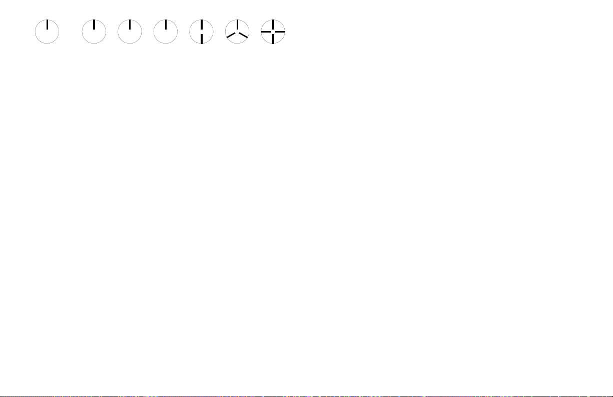
If the speed of rotation is within the range of the stroboscope, start at the
highest flash rate and adjust the flash rate down. At some point you will
stop the motion with only a single reference point of the object in view.
Note that at a flash rate twice the actual speed of the image you will see
two images (reference points). As you approach the correct speed you
may see three, four or more images at harmonics of the actual speed. The
first SINGLE image you see is the true speed. To confirm the true speed,
note the reading and adjust the stroboscope to exactly half this reading, or
just press the ÷2 button. You should again see a single image (which may
be phase shifted with respect to the first image seen).
For example, when viewing a shaft with a single key way you will see one
stationary image of the key way at the actual speed and at 1/2,1/3,1/4, etc,
of the actual speed. You will see 2 images of the key way at 2 times the
actual speed, 3 key way at 3 times, etc.
equals the shaft’s Revolutions Per Minute (RPM) at the highest
flash rate that gives only one stationary image of the key way.
The Flashes Per Minute (FPM)
14
15
 Loading...