

Page 1
Nova-Strobe dax
and / et / y
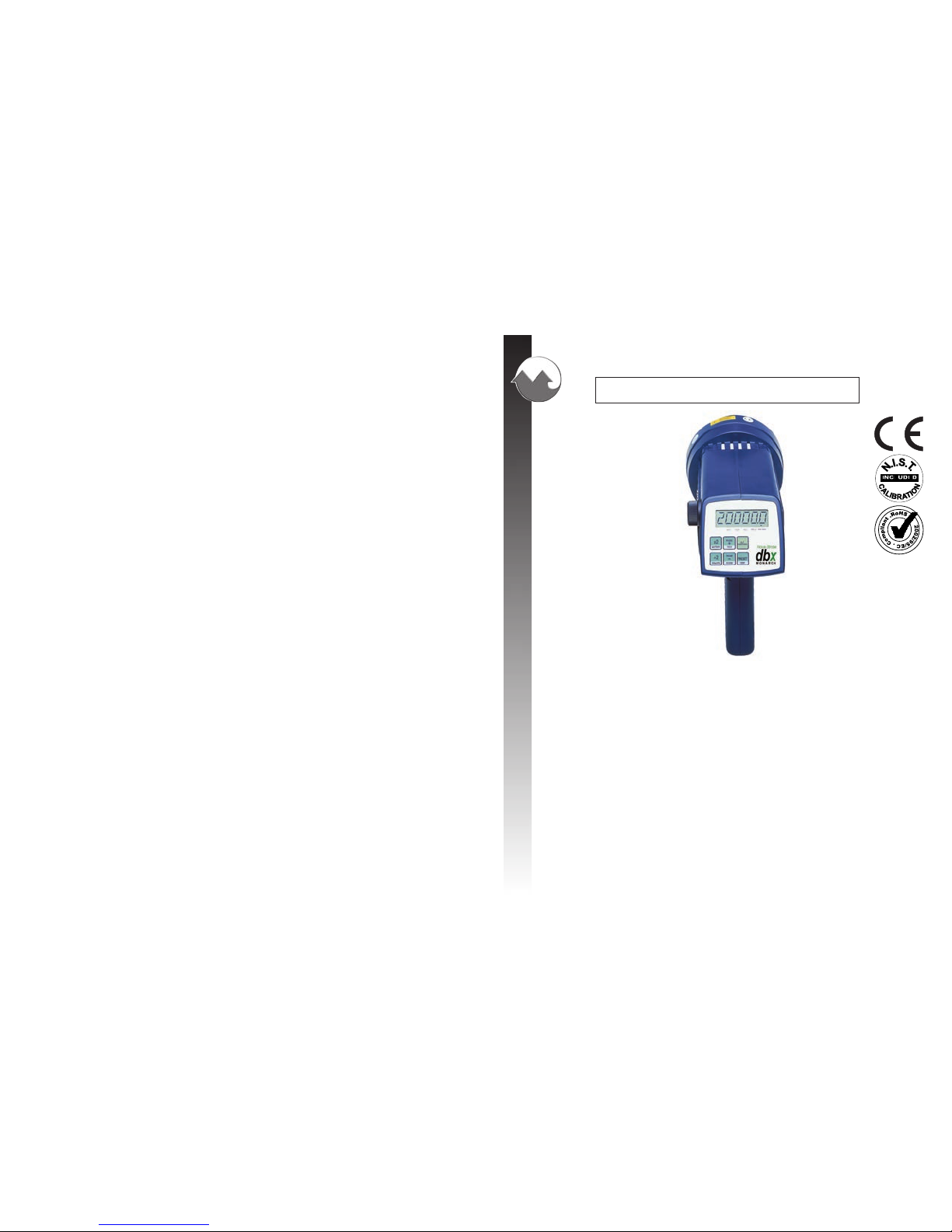
Nova-Strobe dbx
Portable Deluxe Stroboscopes
Stroboscopes portables de qualité supérieure
Estroboscopios Portátiles de lujo
MONARCH INSTRUMENT
Instruction Manual
15 Columbia Drive
Amherst, NH 03031 USA
Phone: (603) 883-3390
Fax: (603) 886-3300
E-mail: support@monarchinstrument.com
Website: www.monarchinstrument.com
(Nova-Strobe dbx shown /
montré / mostrado)
Impreso en los EEUU.
El derecho de autor 2010 Monarch Instrument, reservó bien
1071-4203-514R
1071-4203-714R
- 0510
Distributed by MicroDAQ.com, Ltd
www.MicroDAQ.com
(603) 746-5524
Page 2
Safeguards and Precautions
1. Read and follow all instructions in this manual carefully, and
retain this manual for future reference.
2. Do not use this instrument in any manner inconsistent with
these operating instructions or under any conditions that
exceed the environmental specifications stated.
3. Certain strobe frequencies can trigger epileptic seizures in
those prone to that type of attack.
4. Users should not stare directly at the light source.
5. Prolonged exposure to the light can cause headaches in some
people.
6. Objects viewed with this product may appear to be stationary
when in fact they are moving at high speeds. Always keep a
safe distance from moving machinery and do no touch the
target.
7. There are lethal voltages present inside this product. Refer to
the section on Lamp Replacement before attempting to open
this product.
AC Stroboscopes that have three wire mains cable must
have the earth wire connected to a suitable Earth point.
8. Do not allow liquids or metallic objects to enter the ventilation
holes on the stroboscope as this may cause permanent
damage and void the warranty.
9. Do not allow cables extending from unit to come into contact
with rotating machinery, as serious damage to the equipment,
or severe personal injury or death may occur as a result.
LA DECLARACION DE Ce DE LA CONFORMIDAD
Cuando Fabrica:
Monarch Instrument
La división del Monarch International Inc.
15 Columbia Drive, Amherst NH 03031 USA
declara bajo el Monarch’s única responsabilidad que el product:
a que esta declaración relaciona está en la
conformidad con los estándares siguientes:
y por lo tanto se conforma con los requisitos del Concilio Directivo 2004/108/EG
que relaciona la compatibilidad electromagnéticos y 2006/95/EC que relaciona a la
directiva baja del voltaje cuando operado de acuerdo con la guía de usuario. EMC
que prueba de este producto fue realizado por Retlif Testing Laboratories, NH (el
Archivo R-4702N-5).
Nombre: Serie Nova-Strobe X
Modelo: bbx, dbx, pbx, vbx
15th January, 2010
El fabricante (Amherst,NH) Alan Woolfson, Vice Presidente que Dirige (Autorizó Firma)
EN61326:1997 EMC /A1:1998/A2:2001/A3:2003 La Clase A
Específicamente CISPR 16-1:2003/CISPR 16-2:2003
EN55011:1998/A1:1999/A2:2002 EN61000-4-2 EN61000-4-3
EN61010-1:2001-2 Norma de Seguridad
Distributed by MicroDAQ.com, Ltd www.MicroDAQ.com (603) 746-5524
Page 3
10. This instrument may not be safe for use in certain hazardous
environments, and serious personal injury or death could occur
as a result of improper use. Please refer to your facility’s
safety program for proper precautions.
11. The Nova-Strobe bbx contains Nickel Metal Hydride batteries
which must be disposed of in accordance with Federal, State,
& Local Regulations. Do not incinerate. Batteries should be
shipped to a reclamation facility for recovery of the metal and
plastic components as the proper method of waste
management. Contact distributor for appropriate product
return procedures.
12. This instrument is not user serviceable. For technical
assistance, contact the sales organization from which you
purchased the product or Monarch Instrument directly.
In order to comply with EU Directive 2002/96/EC on Waste
Electrical and Electronic Equipment (WEEE): This product
may contain material which could be hazardous to human health
and the environment. DO NOT DISPOSE of this product as unsorted municipal waste. This product needs to be RECYCLED in
accordance with local regulations, contact your local authorities
for more information. This product may be returnable to your distributor for
recycling - contact the distributor for details.
Monarch Instrument’s Limited Warranty applies. See
www.monarchinstrument.com for details.
Warranty Registration and Extended Warranty coverage available
online at www.monarchinstrument.com.
LA DECLARACION DE Ce DE LA CONFORMIDAD
Cuando Fabrica:
Monarch Instrument
La división del Monarch International Inc.
15 Columbia Drive, Amherst NH 03031 USA
declara bajo el Monarch’s única responsabilidad que el product:
a que esta declaración relaciona está en la
conformidad con los estándares siguientes:
y por lo tanto se conforma con los requisitos del Concilio Directivo 2004/108/EG
que relaciona la compatibilidad electromagnéticos y 2006/95/EC que relaciona a la
directiva baja del voltaje cuando operado de acuerdo con la guía de usuario. EMC
que prueba de este producto fue realizado por Retlif Testing Laboratories, NH (el
Archivo R-4702N-4). La seguridad que prueba por el Archivo Técnico de la
Construcción NSXDA-0207.
Nombre: Serie Nova-Strobe X
Modelo: bax, dax
15th January, 2010
El fabricante (Amherst,NH) Alan Woolfson, Vice Presidente que Dirige (Autorizó Firma)
EN61326:1997 EMC /A1:1998/A2:2001/A3:2003 La Clase A
Específicamente CISPR 16-1:2003/CISPR 16-2:2003
EN55011:1998/A1:1999/A2:2002 EN61000-4-2 EN61000-4-3
EN61000-4-4 EN61000-4-5 EN6100-4-6 EN6100-4-3
EN61010-1:2001-2 Norma de Seguridad
Distributed by MicroDAQ.com, Ltd www.MicroDAQ.com (603) 746-5524
Page 4

T ABLE OF CONTENTS
T ABLE OF CONTENTS
1.0 OVERVIEW ..........................................................................E-1
1.1 Display Panel / Definition of Buttons ........................ E-1
2.0 PREPARA TION FOR USE ..................................................... E-3
2.1 Power.........................................................................E-3
2.2 Input / Output Connections ....................................... E-3
3.0 MENU ...................................................................................E-5
4.0 OPERATION.........................................................................E-6
4.1 Internal Mode - Standard Strobe Operation ............ E-6
4.2 Internal Mode - T ACH Frequency Generator ............ E-9
4.3 External Input Mode .................................................. E-9
4.4 Tachometer Mode - External Input Required.........E-10
4.5 Power Up Features .................................................E-10
5.0 USING THE STROBOSCOPE TO MEASURE RPM ............. E-11
6.0 LAMP AND FUSE REPLACEMENT ....................................E-13
6.1 Lamp Replacement .................................................E-13
6.2 Fuse Replacement ..................................................E-15
7.0 BA TTERY POWERED MODELS ONL Y ...............................E-16
7.1 Low Battery Indication ............................................E-16
7.2 Charging the Batteries............................................E-17
7.3 Battery Disposal ...................................................... E-18
8.0 SPECIFICATIONS...............................................................E-18
9.0 OPTIONS AND ACCESSORIES .........................................E-21
9.0 OPCIONES Y ACCESORIOS
C-4027 El conjunto de aparear 1/8 pulgada (3.5mm) tapones estéreos
de teléfono (proporcionar TTL el poder de la señal y el sensor)
CA-4044-6 6 pie {1.8m} la Entrada/cable de Producción, 1/8 pulgada
{3.5mm} tapón masculino de teléfono al conector masculino
de BNC
CA-4045-6 6 pie {1.8 M} la Entrada/cable de Producción, 1/8 pulgada {3.5
mm} tapón masculino de teléfono a 1/8 pulgada {3.5 mm}
tapón masculino de teléfono para luces estroboscópicas de
encadenar de daysi juntos
CC-7 Cerrar con picaporte que lleva el caso para la luz Estroboscópica
con la provisión para accesorios
L-1903 Lámpara digital de reemplazo de Estroboscopio
PSC-2U Recharger universal, 115/230 Vac con EEUU, U.K., AU,
Tapones de Adaptador de euro para la batería operaron NuevoLUZ Estroboscópicas
ROS-P El Sensor Optico remoto con 8 pie {2.5m} cable para provocar
luz estroboscópica
T-5 La cinta reflectora - 5 pie {1.5m} el rollo, 0.5 pulgada {12.7
mm} lejos
MT-190P El Sensor/Amplificador magnético del Disparador con 8 pie
{2.5m} cable para provocar luz estroboscopica
IRS-P El Sensor infrarrojo para el uso sin el objetivo reflector en 0.5
pulgada {12 mm} el espacio con 8 pie {2.5m} cable para
provocar luz estroboscópica
SPC-1 Salpique la prueba la Cubierta Protectora para la Batería Accionó
luz Estroboscópica SOLO
S-21
Distributed by MicroDAQ.com, Ltd www.MicroDAQ.com (603) 746-5524
Page 5
E-1
1.0 OVERVIEW
All descriptions in this manual apply to both the battery powered (dbx)
and AC mains powered (dax) digital stroboscopes except where noted.
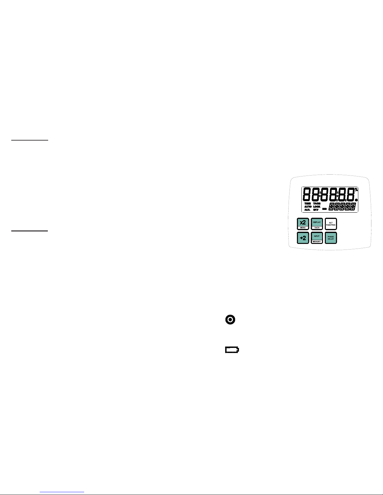
1.1 Display Panel / Definition of Buttons
The display panel consists of
a backlighted liquid crystal
display with six numeric digits
on top and five alphanumeric
digits on the bottom, which
indicate modes, flash rates, etc.
(see Figure 1).
Additional information
displayed include:
TIME Unused
AUTO Unused
ALT
. Indicates
alternate function of each button (lower section) and
knob will be used
TACH Tachometer Mode active (strobe won’t flash)
LOCK Unused
EXT External Input Mode active
On Target Indicator for Tachometer Mode and
Remote Sensor in External Mode
- - - - - Indicates input frequency exceeds the limit of the
stroboscope
(Battery Powered Model Only) Low Battery
indication, see section 7.0
Figure 1 Display Panel
S-20
dbx Especifico:
El disparador para Destellar la Demora 5 µsec típico
Poder de Entrada La batería accionó: Las Baterías Recargables
internas 6 Vdc, recharger Externo de C.A. (100
Vac a 240 Vac, 50/60 Hz)
Produccion Ligera El promedio: 13 Vatios típicos >4000 FPM
Instantáneo (por el destello): 230 mJoule típico
a 4000 FPM
Corra Tiempo 2 horas típicas en 1800 FPM, y más de 1 hora
en 6000 FPM con baterias cargadas
Cargue Tiempo 4-5 horas típicas con PSC-2U
Peso 1.875 lbs {0.8505 kg) including batteries
dax Específico:
El disparador para Destellar la Demora 5 µsec típico
Poder de Entrada C.A. accionó: 115 Vac O 230 V ac, 35VA (ordenó
como)
Produccion Ligera El Poder medio: 15.5 Vatios típicos > 4000
FPM
Instantáneo (por el destello): 230 mJoule típico
a 4000 FPM
Corra Tiempo Continuo dentro de limitaciones de temperatura.
Las aberturas no deben ser restringidas. La
unidad debe estar horizaontal.
Peso 1.55 lbs {0.70 kg}
Distributed by MicroDAQ.com, Ltd www.MicroDAQ.com (603) 746-5524
Page 6

E-2
Below the display are six membrane buttons which control the operation
of the Stroboscope. They are:
Multiplies flash rate by 2 times
ALT Function - Starts Menu (See section 3.0)
Hold when powering up to show all segments, then
Rev # and display test
Divides flash rate by 2
Hold when powering up to reset factory defaults
Toggles display between RPM and RPS
ALT Function - Toggles Tach Mode (flashing) on/off
Manually toggles between Internal and External Modes
AL T Function - Memory - Reads and Stores 9 preset
flash rates
Activates Alternate Function for buttons (lower section)
and knob
In Internal Mode, toggles between normal flash rate
adjust and “phase” adjust
The ALT FUNCTION button toggles AL T
. in the display. When AL T . is
displayed, the buttons will perform their secondary function listed in
the lower section of each button. It also changes how the tuning knob
works.
S-19
El despliegue Actualiza la Tasa 0.5 segundo típico
Entrada externa TTL Compatible (pk 24V Max), 500 anchura de pulso
de min de nanosec, la orilla Positiva o Negativa provocó
(menú seleccionable)
Pulso de Salida 40 µsec pulso positivo/negativo (menú seleccionable),
3.3 Vdc típico
La nota: dax - los conectores de Entrada-Salida aislaron
del poder De C.A
Base de Tiempo Oscilador Fijo ultra de Cristal
Despliegue El despliegue de VCL con 6 numérica 0.506 pulgada
{12.85mm} los dígitos altos y 5 alfanumérica 0.282
pulgada {7.17 mm} los digitos altos
Indicadores El nivel de la batería, En el Objetivo, En AL T , En TACH,
y En iconos de EXT
Ajuste de Perilla El interruptor Rotatorio digital con 36 detents por
revolución; la V elocidad sensible
Memoria Dure poniendo antes poder es recordado hacia abajo y
es restaurado en próximo poder arriba. 9 destello de
settable de usuario valora.
Duracion Rapida 10-25 microsegundos (el auto ajusta con la tasa rápida)
El T ubo rápido (Lámpara) la vida 100 millones destellan
Este producto es diseñado para estar a salvo para uso interior bajo las
condiciones siguientes (por IEC61010-1).
T emperatura operadora 32-104 ºF {0-40 ºC}
LA NOT A: La seguridad la característica térmica pondrá la unidad
en el Modo de T ACH (las paradas que destellan) en caso
de recalentar interno.
Humedad Maximun humedad relativa 80% para la
temperatura hasta 88 ºF {31 ºC} disminuyendo
linealmente a 50% de humedad relativa en 104
ºF {40 ºC}
Distributed by MicroDAQ.com, Ltd www.MicroDAQ.com (603) 746-5524
Page 7
E-3
2.0 PREPARATION FOR USE
The Strobe may be hand held or mounted on a tripod or other user supplied
bracket using the ¼-20 UNC bushing at the base of the handle.
2.1 Power
The AC powered strobe must have its power cord plugged into an AC
outlet (115Vac or 230V ac).
The battery powered strobe has internal rechargeable batteries. The
unit should be charged before use (see section 7.0). The actual operating
time of the stroboscope depends on the flash rate and duty cycle of
operation. Slower flash rates (below 4,000 FPM) increase the operating
time. Note that the strobe will not operate from the recharger supplied
with the unit.
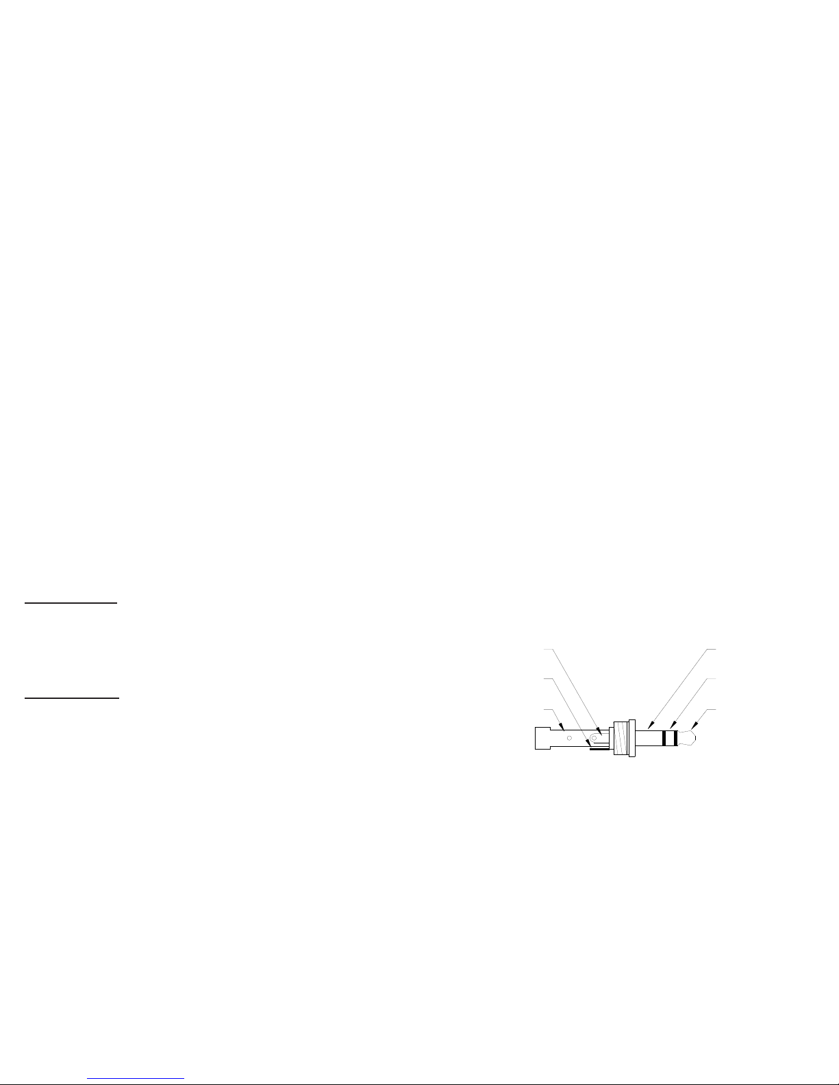
2.2 Input / Output Connections
The strobe has input and output jacks on the left side of the stroboscope.
These can be used for external triggering or synchronization (daisy
chaining two or more strobes). These jacks accept 1/8" (3.5mm) phone
plugs (input - stereo, output - mono). The input and output are TTL
compatible. See Figures 2 and 3 for connector connection detail.
Signal Input
+6V Out to
Sensor
Common
(GND)
Common
(GND)
+6V Out to
Sensor
Signal Input
Figure 2 Input Connector Detail (Stereo plug)
S-18
pico. Si las baterías no son cargadas a 100% de regulary, las baterías
perderán la capacidad.
7.3 Disposición de Batería
Antes de deshacer de la luz estroboscópica a pilas, el usuario debe
quitar las baterías de Níquel-Metal Hydride. Para hacer esto, quite el
lente, el reflector y la lámpara como detallado en la sección del Reemplazo
de Lámpara. Esto expondrá cuatro (4) los tornillos que deben ser
quitados tan la envoltura de reflector puede ser desmantelada. Hay
cuatro (4) los tornillos de addiotionsl en la mitad del caso frente a los
gatos de la entrada y la producción que debe ser quitado. Las mitades
del caso ahora pueden ser separadas, exponiendo las baterías. Quite los
cables de la cinta de baterías y lugar sobre las terminales de batería para
prevenirlos de shorting. Las baterías deben ser mandadas a un reciclaje
central o vueltos a la fábrica. El resto de las partes ahora puede ser
deshecho de.
8.0 ESPECIFICACIONES
El Modo Interno:
La Gama Rapida 30-20,000 FPM (Destella por Minuto)
Certeza Rapida de Tasa 0.004% de escenarios o ± dura el dígito
Resolucion Rapida de Tasa 0.01 a 1 FPM (menú seleccionable), 0,1 FPM
la resolución máx Encima 9,999.99 FPM
El Despliegue actualize la Tasa Instantaneo
El Modo Externo:
La Gama rápida y Demuestra las tasas rápidas, modo-externos y
mismo que internas a 0 son aceptables
Medidas de Tacometro 5 a 250,000 RPM
La certeza: ± 0.001% de la lectura o ±
dura el dígito
Distributed by MicroDAQ.com, Ltd www.MicroDAQ.com (603) 746-5524
Page 8
E-4
The input jack (p pointing into socket) enables an external signal to
trigger the strobe. Inserting a plug into the input jack will automatically
put the strobe into the External Input Mode. The INPUT button can
be used to toggle between Enternal Input Mode and Internal Mode.
When the plug is removed, the strobe will be put back into the Internal
Mode. The polarity of the input pulse can be set in the MENU
options.
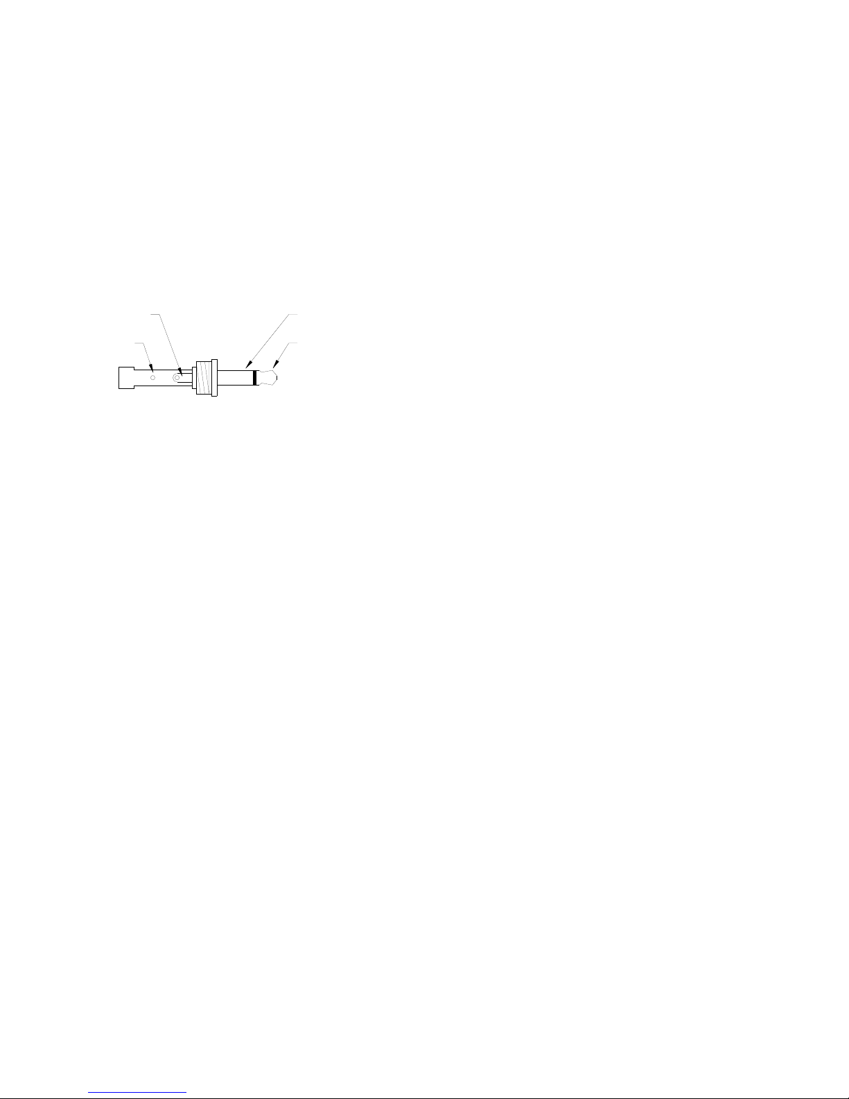
With no external input, the output jack (q pointing away from socket)
provides a TTL compatible pulse from the strobe’s internal oscillator.
If an external input is applied, the output pulse is in sync with the
input pulse. This output pulse may be used to trigger a second
stroboscope synchronously to illuminate larger areas. Many strobes
can be “daisy chained”. The output jack of one strobe is connected to
the input jack of the next strobe causing all the strobes to flash together
and be controlled by the first strobe in the chain. The polarity of the
output pulse can be set in the MENU options.
Pulse Output
from Strobe
Common
(GND)
Common
(GND)
Pulse Output
from Strobe
Figure 3 Output Connector Detail (Mono plug)
S-17
La luz Estroboscópica tiene una característica de la protección que
previene la luz estroboscópica de operar si el voltaje de batería es
demasiado bajo. Esta condición es indicada por ningún destello y
las exposiciones del despliegue “LO BA T” (“AQUI BATEA”). En
este momento las baterías deben ser recargadas. Recuerde de liberar el
interruptor del disparador.
7.2 Cargar las Baterías
La unidad puede ser recargada en tiempo. Usted no necesita esperar
hasta que la batería baja, la condición sea indicada.
Para cargar la batería luz estroboscópica accionada con el
recharger:
1. Libere el disparador tan la luz estroboscópica está apagada.
2. Tape el cable de recharger en el enchufe de recharger (localizó
debajo del entrepaño del despliegue detrás del asidero).
3. Tape el rechar ger en una salida de pared de red de C.A.
El CUIDADO El uso de rechargers de otra manera que
el uno suministrado (PSC-2U) dañarán el
estroboscopio y vaciarán la garantía.
Cuándo el tapón de recharger es metido en el gato de recharger, la luz
estroboscópica entrará el Modo que Carga. Cerciórese el interruptor
del disparador no es deprimido. La luz estroboscópica no hará nada al
cargar (por ejemplo. no destellará y los botones no tienen función).
Cuándo la luz estroboscópica carga, la luz estroboscópica indicará
CHRGE en el derecho inferior del despliega. El recharger cargará
rápidamente las baterías para acerca de 4-5 horas y entonces chorreará
un poco la carga las baterías.
Permita el recharger para cargar las baterías hasta que el despliegue
muestre HECHO (DONE) para el desempeño de la vida de batería de
Distributed by MicroDAQ.com, Ltd www.MicroDAQ.com (603) 746-5524
Page 9

E-5
3.0 MENU
The strobe has a Menu which allows the user to select settings such as
number of decimal places, backlight on or off and positive or negative edge
for input and output signal.
To enter the MENU:
1. Press the ALT FUNCTION button and then the MENU button.
2. SETUP and the menu option will be displayed.
3. Turn the tuning knob to cycle through the main menu options.
4. Once the desired menu option is displayed, press the MENU button to
select it. Press any other button to cancel.
5. Turn the tuning knob to edit the menu option setting.
6. Press the MENU button to save your changes. Press any other button
to cancel.
7. Press any button other than MENU to exit the Main Menu.
8. DONE will be displayed.
Below is a list of the menu items:
DECPT- Decimal Point (none, 1 or 2)
BLITE- Backlight (Yes=On or No=Off)
INPUT- Positive (pos) or Negative (neg) Edge for Input Signal
OUTPT- Positive (pos) or Negative (neg) Edge for Output Signal
S-16
7.0 LA BA TERIA ACCIONO LOS MODELOS SOLO
El Nova-Strobe dbx es quedado con NiMH recargable (Metal de Níquel
Hydride) baterías. Estas baterías contienen menos metales tóxicos que NiCD
(Cadmio de Níquel) y son clasificados actualmente “ambientalmente
amistoso”. Ellos tienen también 30% más capacidad que baterías de NiCD
del mismo tamaño.
Como NiCDs, baterías de NiMH son propenso a la auto-descarga - 10
a 15% de la carga son perdidos en las primeras 24 horas entonces continúa
a razón de 0,5 a 1% por día. Para el desempeño máximo, cargue las baterías
apenas antes del uso.
Cuándo no en uso, las baterías deben ser cargadas por lo menos cada tres
meses, de otro modo la capacidad de batería será reducida o las baterías
pueden llegar a ser inutilizables.
Cargue las baterías utilizan antes y permiten 3-5 ciclos de cargar y
descargar para baterías para alcanzar la capacidad repleta.
El cerco contiene la electrónica del control a carga sin peligro y
apropiadamente las baterías. Nunca quite las baterías del cerco y la tentativa
para cargar externamente. Siempre utilice el corcel suministrado
(PSC-2U).
7.1 Indicación baja de Batería
Cuándo las baterías son cargadas, no habrá icono Bajo de Batería.
Cuándo las baterías son bajas, el icono Bajo de Batería parpadeará en el
despliega. La luz estroboscópica todavía puede ser utilizada para un
tiempo corto.
Icono Bajo de Batería = Resuma Parpadear (muy poco tiempo
dejó)
Distributed by MicroDAQ.com, Ltd www.MicroDAQ.com (603) 746-5524
Page 10

4.0 OPERATION
To turn on the stroboscope, depress and hold the trigger. The trigger may be
locked in position using the side locking button. To lock the stroboscope on,
depress the trigger as far as it will go and then press the locking button. Once the
locking button is set you may release the trigger and the trigger will be held in
place. To unlock the stroboscope, simply depress the trigger and then release.
NOTE: Unit must power down completely (OFF will be displayed and then
disappear) before unit will power on again. This is normal operation.
There are three major operating modes for the Strobe. These are Internal,
External Input and Charging (Battery powered model only). In the
Internal Mode, the knob adjusts the flash rate. In the External Input
Mode, an external signal is used to trigger the flash and the knob has no
effect. The Charging Mode (Battery powered model only) is when the
strobe has the battery recharger plugged into it. The strobe will continuously
display the state of the battery charge while being recharged.
4.1 Internal Mode - Standard Strobe Operation
In the Internal Mode the stroboscope generates it’s own signals and
functions like a tunable stroboscope. The strobe is in the Internal
Mode when nothing is plugged into the input jack or when manually
set using the INPUT button.
To change the flash rate:
With the power on, turn the knob counter clockwise to increase the flash
rate and clockwise to decrease it. The knob is velocity sensitive. Turn the
knob slowly to have each “click” is equal to 0.01 FPM. Turning the knob
more quickly will adjust the FPM by larger steps. When adjusting flash
rate, quickly turn the knob (or use the x2 or ÷2 buttons) to coarsely
change the FPM. Then slowly turn the knob for fine adjustments.
E-6 S-15
4. Vuelva a instalar el reflector y entonces posicione el lente anterior
en el igualar del lugar los cortes en el lente con las dos pequeñas
etiquetas en la envoltura para prevenir la rotación de lente (ve la
figura 4). Empuje las etiquetas en el borde anterior exterior y
apriete el lente en el lugar.
6.2 Funda el Reemplazo
Bajo condiciones de funcionamiento normales, el fusible dentro del
estroboscopio nunca debe soplar
. Los ejemplos de condiciones de
funcionamiento anormales serían las materias extranjeros que entran la
luz estroboscópica, tal como agua, la pulpa, la tinta, etc.
La C.A. Accionó estroboscopio tiene un fusible reemplazable dentro
de la unidad, que puede ser conseguir acceso a quitando el lente y el
reflector - se refiere para figurar 4. Si las necesidades de fusible para ser
reemplazadas, reemplacen sólo con un fusible del mismo tipo y el
valor: El Golpe rápido - 750mA, 2AG.
La ADVERTENCIA: Antes procurar para reemplazar el
fusible, la marca segura el
estroboscopio es apagado y cualquier
cuerda de red es quitada de la salida
de C.A. Permita la lámpara para
refrescar esperar por lo menos 5
minutos.
La Batería Accionó estroboscopio tiene un fusible de resettable, que
repondrá una vez condiciones son normales otra vez.
Distributed by MicroDAQ.com, Ltd www.MicroDAQ.com (603) 746-5524
Page 11
E-7
NOTE: There are maximum and minimum values in each mode
beyond which you cannot adjust. If you are adjusting the
rate and you reach a value which on the next increment would
exceed the maximum flash rate, the display will not increment.
The same is true if you try to adjust the flash rate below the
minimum flash rate.
T o multiply or divide the current flash rate by 2:
In addition to the knob, there are two buttons on the display panel
marked x2 and ÷2. This enables the user to instantly double or halve
the reading on the display to the maximum or minimum values allowed.
This feature is useful for checking harmonics in the internal flashing
mode.
Alternate Knob Function (multiple by 2, 3, 4, 5, etc.)
The tuning knob functions differently when ALT
. is displayed. The
current flash rate is used as an adder. The knob will add (counter
clockwise) or subtract (clockwise) that initial flash rate for each “click”
the knob is turned. This in effect allows the user to multiply the initial
flash rate by 2, 3, 4, 5, etc up to the maximum flash rate. This is very
helpful on fan blades. Using this feature, one can superimpose the
blades on top of each other and check for blade tracking, bent blades,
lead and lag tests, etc.
For example: A 3 bladed fan is spinning at 3600 RPM. The strobe is
flashing at 3600 FPM. Press the ALT FUNCTION button to display
ALT. Then turn the knob counter clockwise 2 clicks. The strobe will
now flash at 10,800 FPM (effectively 3600 times 3). The fans blades
will be all superimposed on each other. One can now see if the blades
are out of alignment, bent, etc. by viewing the blades from the front or
viewing from the side edge of the blades.
S-14
no curiosear la etiqueta más que es necesario para libertar el lente.
El reflector es contenido el lugar por el lente anterior y se aflojará,
pero no es necesario para quitar el reflector.
2. Tenga la lámpara con una tela entre su índice y el pulgar y lo mece
apoya y adelante suavemente al sacando. No procure girar la
lámpara. La Lámpara es socketed y saldrá fácilmente cuando tirado.
La Advertencia: no toque la nueva lámpara con dedos
descubiertos.
3. Las lámparas son polarizadas y deben ser puestas en el enchufe
que empareja la polaridad. Utilizar una hilas libertan tela, el
igual arriba el punto rojo en el tapón con el punto rojo en el
enchufe y mecen suavemente la lámpara al empujar en lugar (V ea
la Figura 4). Cerciórese lámpara está en recto y centrado en el
hoyo de reflector.
El CUIDADO: No permita el reflector para contactar la
lámpara.
Figura 4 Reemplazo de Lámpara
Los Puntos
Rojos
Los Cortes
Distributed by MicroDAQ.com, Ltd www.MicroDAQ.com (603) 746-5524
Page 12

E-8
To select a flash rate from a Preset (memory) location:
1. Press the ALT FUNCTION button and then the MEMORY button.
2. READ will be displayed.
3. Turn the tuning knob to cycle through the preset flash rates.
4. Once the desired flash rate is displayed, press the MEMORY
button to select it. Press any other button to cancel.
5. DONE will be displayed.
To store the current flash rate in a Preset (memory) location:
1. Press the ALT FUNCTION button and then the MEMORY button.
2. READ will be displayed.
3. Do NOT turn the knob and press the MEMORY button again.
4. STORE will be displayed.
5. Turn the tuning knob to cycle through the memory locations.
6. Once the desired memory location is displayed, press the
MEMORY button to store the current flash rate in that location.
Press any other button to cancel.
7. DONE will be displayed.
Internal “Phase” Delay
Once the flash rate has been adjusted to give a stopped motion image,
the PHASE DELAY button may be used with the knob to increase or
decrease the phase of the reference mark location. Use the PHASE
DELAY button and knob to bring a reference mark, such as a key way,
into your line of sight.
To adjust the “Phase” Delay:
1. Press the PHASE DELAY button.
2. PHASE will be displayed on the bottom line and the current flash
rate will be displayed on the top line.
S-13
Si un Sensor Optico Remoto o Sensor Magnético son utilizados para
presentir un pulso por la revolución (el modo externo), la lectura de salida
demostrará directamente en RPM (FPM) sin cualquier ajuste requerido.
En casos cuando usted puede cerrar el dispositivo e instalar un pedazo de
cinta reflectora, entonces un tacómetro óptico es más fácil de utilizar para la
medida de RPM. Estroboscopios deben ser utilizados cuando usted no
puede cerrar el dispositivo. El ojo humano no es engañado fácilmente a ver
una imagen parada por un estroboscopio cuando la tasa rápida es más lenta
que 300 FPM. Por lo tanto, estroboscopios son casi igual imposibles utilizar
debajo de 300 FPM para la inspección o para medir RPM.
6.0 LA LAMPARA
Y FUNDE EL REEMPLAZO
6.1 Reemplazo de lámpara
La advertencia: Antes procurar para quitar la lámpara, la
marca segura el estroboscopio es
apagado y cualquier cuerda de red es
quitada de la salida de C.A. Permita la
lámpara para refrescar esperar por lo
menos 5 minutos.
El estroboscopio es diseñado para descargar los voltajes altos internos
dentro de 30 segundos. Sin embargo, el cuidado debe ser ejercitado al
reemplazar la lámpara.
La lámpara puede ser reemplazada utilizando apenas un destornillador
de bolsillo. No es necesario para quitar ningún tornillo para
reemplazar la lámpara.
Para cambiar la Lampara:
1. Empuje aparte las dos etiquetas en el lado del reflector que alberga
y quita el lente que utiliza un pequeño destornillador para ayudar
a curiosear una etiqueta y levantar el lente. T ome el cuidado para
Distributed by MicroDAQ.com, Ltd www.MicroDAQ.com (603) 746-5524
Page 13
E-9
3. Turn the tuning knob to adjust the location (phase) of the reference
mark.
4. Press the PHASE DELAY button again to turn the “Phase” Delay
mode off.
4.2 Internal Mode - TACH Frequency Generator
In the Internal Mode, the strobe can be used as a frequency generator
(outputting TTL pulses) without having the strobe flash. The pulse
output will still occur at the flash rate; the strobe is just not flashing.
To stop flashing:
Press the ALT FUNCTION button and then the TACH button. The
TACH icon will be displayed.
T o start flashing again:
Press the ALT FUNCTION button and then the TACH button. The
TACH icon will go away and the strobe will start flashing again.
4.3 External Input Mode
In the External Input Mode the user can’t make any flash rate adjustments.
The flash rate is a function of the input signal. This mode is used to
synchronize the flash to an external event (for example, from an optical
sensor) to stop or freeze motion. The flash will be triggered on the rising or
falling edge (menu selectable) of the external input pulse.
The strobe is in the External Input Mode whenever there is a plug in
the input jack. When the strobe is in the External Input Mode, EXT
will be displayed.
S-12
Por ejemplo, al ver un túnel con una sola manera clave usted verá una imagen
inmóvil de la manera clave en la velocidad verdadera y en 1/2, 1/3, 1/4, etc.,
de la velocidad verdadera. Usted verá 2 imágenes de la manera clave en 2
veces la velocidad verdadera, 3 manera clave en 3 veces etc.
El Destello Por
Minuto (FPM) iguala las Revoluciones de túneles Por Minuto (RPM)
en la tasa más alta del destello que da sólo una imagen inmóvil de la
llave lejos.
Ejemplo: Se opone girando en 5000 RPM
Si la velocidad está fuera de la gama repleta de la escala del estroboscopio
(14.000 FPM), puede ser medido utilizando el método del cálculo de armonía
y multipoint. La estrella en la tasa más alta del destello y ajusta la tasa
rápida hacia abajo. Usted encontrará múltiples imágenes tan están enterado
de éstos. Note la tasa rápida de la SOLA primera imagen que usted encuentra,
llama esta velocidad “UN”. Continúe disminuir la tasa rápida hasta que
usted encuentre una SOLA segunda imagen. Note esta velocidad como “B”.
Continúe disminuir la velocidad hasta que usted alcance un thrid SOLA
imagen en la velocidad “C”.
Para un dos calculo del punto que la velocidad verdadera es dada por:
RPM = AB/(A-B)
Para un tres calculo de punto:
RPM = 2XY(X+Y)/(X-Y)2 donde
X = (A-B) y
Y = (B-C)
La imagen parada 1/4 tiempos
1/2 tiempos 1 tiempo 2 tiempos
3 tiempos 4 tiempos
Destella Tasa (FPM) 1250 2500 5000 10000 15000 20000
Distributed by MicroDAQ.com, Ltd www.MicroDAQ.com (603) 746-5524
Page 14

E-10
4.4 Tachometer Mode - External Input Required
When an external input is supplied to the unit and the strobe is put in the
Tachometer Mode, the unit will read the signal from the external input
(sensor) and display the reading on the LCD display without flashing the
lamp. The strobe will not flash in the Tachometer Mode.
To enter the External Tachometer Mode:
1. Plug an external input into the unit.
2. Press the ALT FUNCTION button and then the TACH button.
The T ACH icon will be displayed.
NOTE: If the external input signal exceeds the maximum flash rate,
the strobe will go into the Tachometer Mode automatically.
To exit the External Tachometer Mode:
1. Press the ALT FUNCTION button and then the TACH button.
The T ACH icon will go away .
2. The unit will remain in the External Input Mode unless the INPUT
button is pressed to change the mode.
4.5 Power Up Features
When the strobe is powered up it will remember the last settings.
Press and hold the x2/MENU button, then turn on the strobe by
depressing the trigger switch. This will turn on all the display segments
for two seconds or until you release the button. It will then show the
software revision, “REV x.x” and then go through a display diagnostic.
Press and hold the ÷2 button, then turn on the strobe by depressing
the trigger switch. This will restore the factory programmed presets.
S-11
todos los segmentos del despliegue por dos segundos o hasta que usted
libere el botón. Entonces mostrará la revisión de software,
REVOLUCION X.X y entonces atravesará un despliegue diagnóstico.
La prensa y tiene el botón ÷2, entonces vuelta en la luz estroboscópica
deprimiendo el interruptor de tigger. Esto restaurará la fábrica
programada fija.
5.0 UTILIZAR EL ESTROBOSCOPIO PARA
MEDIR RPM
El uso primario para un estroboscopio es de parar el movimiento para
propósitos diagnósticos de inspección. Sin embargo el estroboscopio puede
ser utilizado para medir debe ser visible para el al 360‘ de la rotación (por
ejemplo. El fin de un túnel). Segundo, el objeto debe tener alguna parte
extraordinaria en ello, como un cerrojo, la manera o la imperfección claves
para utilizar como un punto de referencia. Si el objeto para ser visto es
perfectamente simétrico, entonces el usuario necesita marcar el objeto con
un pedazo de cinta o pintura en una sola ubicación para ser utilizado como
un punto de referencia. Mire sólo en el punto de referencia.
Si la velocidad de la rotación está dentro de la gama del estroboscopio, el
comienzo en la tasa más alta del destello y ajusta la tasa rápida hacia abajo.
En algún punto usted parará el movimiento con sólo un solo punto de
referencia del objeto en la vista. Note que en una tasa rápida dos veces ese
tha la velocidad verdadera de la imagen usted verá dos imágenes (puntos de
referencia). Cuando usted se acerca la velocidad correcta usted puede ver
tres, cuatro o más imágenes en armonía de la velocidad verdadera. La SOLA
primera imagen que usted ve es la velocidad verdadera. Para confirmar la
velocidad verdadera, notar la lectura y ajustar el estroboscopio a exactamente
media esta lectura, o apretar apenas el +2 botón. Usted otra vez debe ver
una sola imagen (que puede ser fase cambiada con respecto a la primera
imagen vista).
Distributed by MicroDAQ.com, Ltd www.MicroDAQ.com (603) 746-5524
Page 15

E-11
5.0 USING THE STROBOSCOPE TO MEASURE
RPM
The primary use for a stroboscope is to stop motion for diagnostic inspection
purposes. However the stroboscope can be used to measure speed (in
RPM / RPS). In order to do this several factors need to be considered. First,
the object being measured should be visible for all 360° of rotation (e.g. The
end of a shaft). Second, the object should have some unique part on it, like
a bolt, key way or imperfection to use as a reference point. If the object
being viewed is perfectly symmetrical, then the user needs to mark the
object with a piece of tape or paint in a single location to be used as a
reference point. Look only at the reference point.
If the speed of rotation is within the range of the stroboscope, start at the
highest flash rate and adjust the flash rate down. At some point you will
stop the motion with only a single reference point of the object in view.
Note that at a flash rate twice the actual speed of the image you will see two
images (reference points). As you approach the correct speed you may see
three, four or more images at harmonics of the actual speed. The first
SINGLE image you see is the true speed. To confirm the true speed, note
the reading and adjust the stroboscope to exactly half this reading, or just
press the ÷2 button. You should again see a single image (which may be
phase shifted with respect to the first image seen).
For example, when viewing a shaft with a single key way you will see one
stationary image of the key way at the actual speed and at 1/2,1/3,1/4, etc,
of the actual speed. You will see 2 images of the key way at 2 times the
actual speed, 3 key way at 3 times, etc. The Flashes Per Minute (FPM)
equals the shaft’s Revolutions Per Minute (RPM) at the highest flash
rate that gives only one stationary image of the key way.
S-10
La luz estroboscopica es el Modo De Entrada Externo simper que hay
un tapon en el gato de entrada. Cuando la luz estroboscopica este en el
Modo De Entrada Externo, EXT sera demostrado.
4.4 Modo del Tacómetro – La Entrada Externa
Requirio
Cuando una entrada externa es suministrada a la unidad y la luz
estroboscopica es puesta en el Modo de Tacómetro, la unidad leera la
señal de la entrada externa (sensor) y demostrara la lectura en el
despliegue de VCL sin destellar la lampara. La luz estroboscopica no
destellara en el Modo de Tacómetro.
Para entrar el Modo Externa de Tacómetro:
1. Inserte una entrada externa en la unidad.
2. Apriete el boton de la FUNCION De ALT y entonces el boton de
TACH. El icono de TACH será demostrado.
LA NOT A: Si la señal de entrada externa excede la tasa rapida maxima,
la luz estroboscopica entrara el Modo de Tacometro
automaticamente.
Para salir el Modo Externa de Tacómetro:
1. Apriete el boton de la FUNCION De ALT y entonces el boton de
TACH. El icono de TACH se ira.
2. La unidad se quedará en el Modo de Entrada Externa a menos que
el botón INPUT sea apretado para cambiar el modo.
4.5 Poder Arriba Caracteristicas
Cuando las luces estroboscopicas lo son encendidos recordara los ultimos
scenarios.
La prensa y tiene el botón x2/MENU, entonces vuelta en la luz
estroboscópica deprimiendo el interruptor de tigger. Esto prenderá
Distributed by MicroDAQ.com, Ltd www.MicroDAQ.com (603) 746-5524
Page 16

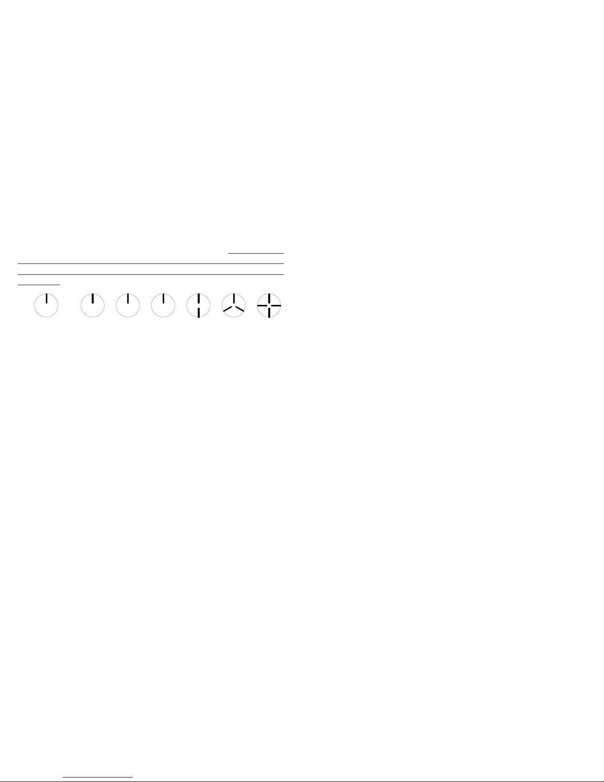
Example: Object Rotating at 5000 RPM
If the speed is outside the full scale range of the stroboscope (20,000 FPM),
it can be measured using the method of harmonics and multipoint calculation.
Start at the highest flash rate and adjust the flash rate down. You will
encounter multiple images so be aware of these. Note the flash rate of the
first SINGLE image you encounter, call this speed “A”. Continue decreasing
the flash rate until you encounter a second SINGLE image. Note this speed
as “B”. Continue decreasing the speed until you reach a third SINGLE
image at speed “C”.
For a two point calculation the actual speed is given by:
RPM = AB/(A-B)
For a three point calculation:
RPM = 2XY(X+Y)/(X-Y)2 where
X = (A-B) and
Y = (B-C)
If a Remote Optical Sensor or Magnetic Sensor is used to sense one pulse
per revolution (External mode), the readout will display directly in RPM
(FPM) without any adjustment required.
In instances when you can shut down the device and install a piece of reflective
tape, then an optical tachometer is easier to use for RPM measurement.
Stroboscopes must be used when you can’t shut down the device. The
human eye is not easily tricked into seeing a stopped image by a stroboscope
when the flash rate is slower than 300 FPM. Therefore, stroboscopes are just
about impossible to use below 300 FPM for inspection or to measure RPM.
Stopped Image 1/4 times 1/2 times 1 time 2 times
3 times 4 times
Flash Rate (FPM) 1250 2500 5000 10000 15000 20000
E-12
Para ajustar la Demora de “Fase”:
1. Apriete el boton de la DEMORA De FASE.
2. PHASE (La FASE) será demostrada en la última línea y la tasa
rápida actual será demostrada en la línea primera.
3. Gire la perilla de la sintonía para ajustar la fase de la llamada.
4. Apriete el boton de la DEMORA De FASE otra vez para apagar
el modo de la Demora de “Fase”.
4.2 Modo Interno – El Generaor de la Frecuencia
de T ACH
En el Modo de Interna, la luz estroboscopica puede ser utilizada como
un generador de frecuencia (produciendo pulsos de TTL) sin tener el
destello estroboscopico. La produccion de pulso ocurrira todavia en la
tasa rapida; la luz estroboscopica apenas no destella.
Para parar destellar:
Apriete el boton de la FUNCION De ALT y entonces boton de T ACH. El
icono de T ACH será demostrado.
Para empezar a destellar otra vez:
Apriete el boton de la FUNCION De ALT y entonces boton de TACH. El
icono de T ACH se ira y la luz estroboscopica empezara a destellar otra vez.
4.3 Modo De Entrada Externo
En el Modo De Entrada Externo que el usuario no puede hacer ajustes
rapidos de la tasa. La tasa rapida es una function de la señal de entrada.
Este modo es utilizado para sincronizar el destello a un acontecimiento
externo (por ejemplo, de un sensor optico) parar o congelar el
moviemiento. El destello sera provocado en el subir o caer la orilla
(menu seleccionable) del pulso de entrada externo.
S-9
Distributed by MicroDAQ.com, Ltd www.MicroDAQ.com (603) 746-5524
Page 17

E-13
6.0 LAMP AND FUSE REPLACEMENT
6.1 Lamp Replacement
WARNING: Before attempting to remove the lamp, make
sure the stroboscope is turned off and any
mains cord is removed from the AC outlet. Allow
the lamp to cool waiting at least 5 minutes.
The stroboscope is designed to discharge the internal high voltages
within 30 seconds. However, caution should be exercised when replacing
the lamp.
The lamp can be replaced by using just a pocket screwdriver. It is not
necessary to remove any screws to replace the lamp.
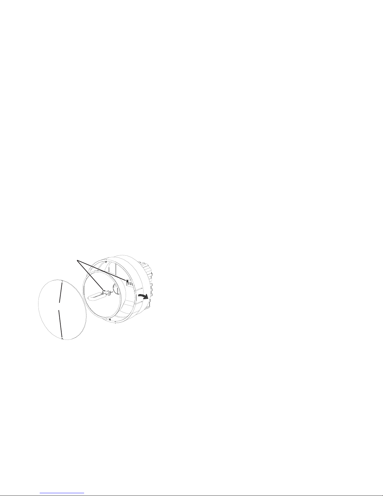
To change the lamp:
1. Push apart the two tabs on the side of the reflector housing and
remove the lens using a small screwdriver to help pry one tab and
lift the lens. T ake care not to pry the tab any more than is necessary
to free the lens. The reflector is held in place by the front lens and
will come loose, but it is not necessary to remove the reflector.
2. Hold the lamp with a cloth between your forefinger and thumb
and rock it back and forth gently while pulling out. Do not attempt
to rotate the lamp. The lamp is socketed and will come out easily
when pulled straight out.
WARNING: Do NOT touch the new lamp with bare fingers.
3. The lamps are polarized and must be put into the socket matching
polarity . Using a lint free cloth, match up the red dot on the
plug with the red dot on the socket and gently rock the lamp
S-8
sobrepuestas en uno al otro. Uno ahora puede ver si las hojas no estan
alineadas, dobladas, etc. viendo las hojas de la frente o viendo de la
orilla del lado de las hojas.
Para escoger una tasa rapida de un Fijó (la memoria) la ubicación:
1. Aprieta el boton de la FUNCION de ALT y entonces el boton de
MEMORIA.
2. READ (LEA) sera demostrado.
3. Gire la perilla de la sintonia al ciclo por las tasas rapidas presents.
4. Una vez que la tasa deseada del destello es demostrada, apriete el
boton de la MEMORIA para escogerlo. Apriete cualquier otro
boton para cancelar.
5. DONE (HECHO) sera demostrado.
Para almacenar la tasa rapida actual en un Fijó (la memoria) la
ubicación:
1. Aprieta el boton de la FUNCION de ALT y entonces el boton de
MEMORIA.
2. READ (LEA) sera demostrado.
3. No gire la perilla y apriete el boton de la MEMORIA otra vez.
4. STORE (La TIENDA) sera demostrado.
5. Gire la perilla de la sintonia al ciclo por las ubicaciones de la
memoria.
6. Una vez que la ubicación deseada de la memoria es demostrada,
apriete el boton de la MEMORIA para almacenar la tasa rapida
actual en esa ubicación. Apriete cualquier otro boton para cancelar .
7. DONE (HECHO) sera demostrado.
La Demora Interna De La “Fase”
Una vez que la tasa rapida ha sido ajutada para dar una imagen parade
del movimiento, el boton de la DEMORA De FASE puede ser utilizado
con la perilla para aumentar o disminuir la fase de la ubicación de
llamada. Utilice el boton de la DEMORA De FASE y perilla para traer
una llamada, tal como una manera clave, en su visual.
Distributed by MicroDAQ.com, Ltd www.MicroDAQ.com (603) 746-5524
Page 18

E-14
while pushing it into place (see Figure 4). Make sure the lamp is
in straight and centered in the reflector hole.
CAUTION: Do NOT allow the reflector to contact the lamp.
4. Reinstall the reflector and then position the front lens in place
matching up the notches on the lens with the two small tabs on
the housing to prevent lens rotation (see Figure 4). Push the tabs
on the front rim outward and press the lens into place.
Figure 4 Lamp Replacement
Red Dots
Notches
S-7
grande. Al ajustar la tasa del destello, girar rapidamente la perilla (o utilizar
el x2 o +2 botones) cambiar toscamente el FPM. Entonces gire lentamente
la perilla para ajustes de multa.
LA NOT A: Hay dos valores maximos y minimos en cada modo mas
alla de que usted no puede ajustar. Si usted ajusta la tasa y
usted alcanza un valor que en el proximo incremento
excederia la tasa rapida maxima, el despliegue no
incrementara. El mismo es verdad si usted trata de ajustar
la tasa rapida debajo de la tasa rapida minima.
Para multiplicar o divider la tasa rapida actual por 2:
Ademas de la perilla, hay dos botones en el entrepaño de espalda
marcaron x2 y ÷2. Esto permite al usuario a duplicar instantaneamente
o para compartir la lectura en el despliegue al maximo o el minimo valor
permitido. Esta caracteristica es util para verificar armonia en el modod
intermitente interno.
Alterne la Funcion de la Perilla (el multiplo por 2, 3, 4, 5, etc.)
La perilla de la sintonia funciona de forma distinta cuando ALT
. es
demostrado. La tasa rapida actual es utilizada como un sumando. La
perilla agregara (contra a la derecha) o (a la derecha) eso inicial destella
la tasa para cada “click” que la perilla es girada. Esto vigente permite al
usuario a multiplicar la tasa rapida inicial por 2, 3, 4, 5, etc. hasta la tasa
rapida maxima. Esto es muy util en hojas de ventilador. Utilizando esta
caracteristica, uno puede sobreponer las hojas encima de uno al otro y
el cheque para rastrear de hoja, hojas dobladas, dirigen y se retrasan las
pruebas, etc.
Por ejemplo: Un 3 ventilador de bladed gira en 3600 RPM. La luz
estroboscopica destella en 3600 FPM. Apriete el boton de la FUNCION
de ALT para demostrar ALT. Entronces gire la perilla contra a la derecha
2 cliques. La luz estroboscopica ahora destellara en 10,800 FPM
(efectivamente 3600 veces 3). Las hojas de ventiladores que todo seran
Distributed by MicroDAQ.com, Ltd www.MicroDAQ.com (603) 746-5524
Page 19

E-15
6.2 Fuse Replacement
Under normal operating conditions, the fuse within the stroboscope
should never blow. Examples of abnormal operating conditions would
be foreign materials entering the strobe, such as water, pulp, ink, etc.
The AC Powered stroboscope has a replaceable fuse inside the unit,
which may be accessed by removing the lens and reflector - refer to
Figure 4. If the fuse needs to be replaced, replace only with a fuse of
the same type and value: Fast Blow - 750mA, 2AG.
WARNING: Before attempting to replace the fuse, make
sure the stroboscope is turned off and any
mains cord is removed from the AC outlet. Allow
the lamp to cool waiting at least 5 minutes.
The Battery Powered stroboscope has a resettable fuse, which will
reset once conditions are normal again.
4.0 OPERACION
Para aprender el estroboscopio, deprimir y tener el disparador. El disparador
puede ser encerrado la posicion que utilize el lado que cierra el boton. Para cerrar
el estroboscopio en, deprime el disparador por lo que ira y entonces apretara el
boton que cierra. Una vez que el boton que cierra le es puesto puede liberar el
disparador y el disparador sera contenido el lugar. Para desatrancar el
estroboscopio, deprime simplemente el disparador y entonces liberacion.
LA NOT A: La unidad debe apagar completamente (OFF será demostrado y
entonces desaparece) antes que unidad enchufará en otra vez. Esto
es operación normal.
Hay tres modos de operadores mayors para la luz estroboscopica . Estos son la
Entradas Internas y Externas y Cargando (Bateria el modelo accionado solo). En
el Modo Interno, la perilla ajusta la tasa rapida. En el Modo de entrada Externo,
una señal externa es utilizada para provocar el destello y la perilla no tiene
efecto. El Modo que Carga (Bateria acciono el modelo solo) es cuando la luz
estroboscopica tiene el rechanger de bateria tapo en ello. La luz estroboscopica
demostrara continuamente el estado de la carga de bateria mientras ser recargado.
4.1 Modo Interno- La Operacion Estroboscopica
Uniforme
En el Modo Interno que el estroboscopico engendra es propias señales y
las funciones como un estroboscopio de tunable. La luz estroboscopica
esta en el Modo Interno cuando nada es tapado en el gato de entrada o
cuando manualmente conjunto que utilize el boton INPUT.
Para cambiar la tasa rapida:
Con el poder en, gire la perilla contra a la derecha para aumentar la tasa
rapida y a la derecha para disminuirlo. La perilla es la velocidad sensible.
Gire la perilla para tener lentamente cada “click” es igual a 0.01 FPM. La
curva que la perilla mas ajustara rapidamente el FPM por pasos mas
S-6
Distributed by MicroDAQ.com, Ltd www.MicroDAQ.com (603) 746-5524
Page 20

E-16
7.0 BATTERY POWERED MODELS ONLY
The Nova-Strobe dbx is fitted with rechargeable NiMH (Nickel Metal
Hydride) batteries. These batteries contain fewer toxic metals than NiCd
(Nickel Cadmium) and are currently classified “environmentally friendly”.
They also have 30% more capacity than NiCd batteries of the same size.
Like NiCds, NiMH batteries are prone to self-discharge - 10 to 15% of
charge is lost in the first 24 hours then continues at a rate of 0.5 to 1% per
day. For maximum performance, charge the batteries just prior to use.
When not in use, the batteries should be charged at least every three months,
otherwise the battery capacity will be reduced or the batteries may become
unusable.
Charge the batteries before use and allow 3-5 cycles of charging and
discharging for batteries to reach full capacity.
The enclosure contains control electronics to properly and safely charge the
batteries. Never remove the batteries from the enclosure and attempt to
charge externally. Always use the charger supplied (PSC-2U).
7.1 Low Battery Indication
When the batteries are charged, there will be no battery indication.
When the batteries are low, the Low Battery icon will blink in the
display. The strobe may still be used for a short time.
Low Battery Icon = Outline blinking (very little time left)
The strobe has a protection feature that prevents the strobe from
operating if the battery voltage is too low. This condition is indicated
by no flash and the display shows “LO BAT”. At this time the
batteries must be recharged. Remember to release the trigger switch.
S-5
causa que todas las luces estroboscopicas destellen junto y sean
controlado por la primera luz estroboscopica en la cadena. La polaridad
del pulso de salida puede ser puesta en las opciones de MENU.
3.0 MENU
La luz estroboscopica tiene un Menu que permite al usuario a escoger los
scenarios tales como el numero de lugares de decimal, alumbra de fondo en
o lejos, y la orilla positive o negative para la señal de la entrada y la produccion
Para entrar a MENU:
1. Apriete el boton de la FUNCION de ALT y entonces el boton de
MENU.
2. Arreglo y la opcion de menu seran demostrados.
3. Gire la perilla de la sinfonia al ciclo por las selecciones principales
del menu.
4. Una vez que la opcion deseada del menu es demostrada, apriete el
boton de MENU para escogerlo. Apriete cualquier otro boton
para cancelar.
5. Gire la perilla de la sintonia para redactor la opcion de menu.
6. Apriete el boton de MENU para salvar cambios. Apriete cualquier
otro boton para cancelar.
7. La prensa cualquier boton de otra manera que MENU para salir el
Menu principal.
8. DONE (HECHO) sera demostrado.
Debajo es una lista de los articulos de menu:
DECPT- Punto decimal (ninguno, 1 o 2)
BLITE- Alumbra de fondo: Yes (Si) = En o No (No) = EN
INPUT- LA ENTRADA- Positivo (el punto de ventas) o Negativo
(neg) la Orilla para la Señal de entrada
OUTPT- Positivo (el punto de ventas) o Negativo (neg) la Orilla para
la Señal de salida
Distributed by MicroDAQ.com, Ltd www.MicroDAQ.com (603) 746-5524
Page 21

E-17
7.2 Charging the Batteries
The unit may be recharged at any time. You do not need to wait until
the low battery condition is indicated.
To charge the batter y powered strobe with the recharger:
1. Release the trigger so the strobe is off.
2. Plug the recharger cable into the recharger socket (located below
the display panel behind the handle).
3. Plug the recharger into an AC mains wall outlet (115/230 Vac).
CAUTION: Use of rechargers other than the one supplied
(PSC-2U) will damage the stroboscope and void
the warranty.
When the recharger plug is inserted into the recharger jack, the strobe
will go into the Charging Mode. Make sure the trigger switch is not
depressed. The strobe will not do anything else when charging (e.g. it
will not flash and the buttons have no function).
When charging, the strobe will indicate CHRGE in the bottom right of the
display. The recharger will fast charge the batteries for about 4-5
hours and then trickle charge the batteries.
Allow the recharger to charge the batteries until the display shows
DONE for peak battery life performance. If the batteries are not charged
to 100% regularly, the batteries will lose capacity.
S-4
El gato de entrada (p señalando en el enchufe) permite una señal externa a
provocar la luz estroboscopica. Meter un tapon en el gato de entrada
pondra automaticamente la luz estroboscopica en el Modo de entrada
Externo. El botón INPUT puede ser utilizado para bascular entre el Modo
de entrada Externo y el Modo Interno. Cuando el tapon es quitado, la luz
estroboscopica sera vuelta a poner en el Modo Interno. La polaridad del
pulso de entrada puede ser puesta en las opciones de MENU.
Con ninguna entrada externa, el gato de salida (q señalando lejos del
enchufe) proporciona un TTL pulso compatible del oscilador interno
de luz estroboscopica. Si una entrada externa es aplicada, el pulso de
salida esta en la sincronizacion con el pulso de entrada. Este pulso de
salida puede ser utilizado para provocar un Segundo sytnchronously
de estroboscopio para iluminar areas mas grande. Muchas luces
estroboscopicas pueden ser “margarita encadeno” estroboscopica que
Salida Pulso
Comun (GND)
Comun (GND)
Salida Pulso
Figura 3 Detalle de Salida del Conector (Mono T apon)
Señale la Entrada
+6V Fuera al
Sensor
Comun (GND)
Comun (GND)
+6V Fuera al
Sensor
Señale la Entrada
Figura 2 Detalle de Entrada del Conector (T apon Estereo)
Distributed by MicroDAQ.com, Ltd www.MicroDAQ.com (603) 746-5524
Page 22

E-18
7.3 Battery Disposal
Prior to disposing of the battery-powered strobe, the user must remove
the Nickel Metal Hydride batteries. To do this, remove the lens,
reflector and lamp as detailed in the Lamp Replacement section. This
will expose four (4) screws that must be removed so the reflector
housing can be dismantled. There are four (4) additional screws in the
case half opposite the input and output jacks that must be removed.
The case halves can now be separated, exposing the batteries. Remove
the cables from the batteries and place tape over the battery terminals
to prevent them from shorting. The batteries should be sent to a
recycling center or returned to the factory. The rest of the parts may
now be disposed of.
8.0 SPECIFICATIONS
Internal Mode:
Flash Range 30 - 20,000 FPM (Flashes Per Minute)
Flash Rate Accuracy 0.004% of setting or ± last digit
Flash Rate Resolution 0.01 to 1 FPM (menu selectable), 0.1 FPM
max resolution above 9,999.99 FPM
Display Update Rate Instantaneous
External Modes:
Flash Range and Display same as internal mode - External flash rates
to 0 are acceptable
Tachometer Measurements 5 to 250,000 RPM
Accuracy: ±0.001% of reading or ± last
digit
Display Update Rate 0.5 second typical
S-3
2.0 PREPARACION PARA EL USO
La luz Estroboscopica puede ser mano tenida o montada en un tripode u
otro usuario suministro parenthesis que utilize el buje de UNC ¼-20 en la
base del asidero.
2.1 Poder
La C.A. acciono luz estroboscopica debe tener su cuenta del poder
tapada en una salida de C.A. (115 Vac o 230 Vac).
La bacteria acciono luz estroboscopica tiene baterias recargables
internas. La unidad debe ser cargada antes uso (vea la seccion 7.0). El
tiempo operador verdadero del estroboscopio depende del ciclo rapido
de la tasa y el deber de la operacion. Las tasas rapidas mas lentas
(debajo de 4.000 FPM) aumenta el tiempo operador. Note que la luz
estroboscopica no operara del recharger suministro con la unidad.
2.2 De Entrada / Las Conexiones de salida
La luz estroboscopica tiene los gastos de la entrada y la produccion en
el lado izquierdo del estroboscopio. Estos pueden ser utilizados para
provocar o sincronizar externos (margarita que encadena dos o mas
luces estroboscopicas). Estos gatos aceptan 1/8” (phone 3.5mm) tapa
(de entrada-estereo, la produccion – mono). La entrada y la produccion
son TTL compatibles. V eal as figures 2 y 3 para el detalle de la conexion
del conector.
Distributed by MicroDAQ.com, Ltd www.MicroDAQ.com (603) 746-5524
Page 23

E-19
External Input TTL Compatible (24V pk max), 500 nanosec
min pulse width,
Positive or Negative edge triggered (menu
selectable)
Output Pulse 40 µsec positive/negative pulse (menu
selectable), 3.3 Vdc typical
Note: dax – Input/Output connectors isolated
from AC power
Time Base Ultra Stable Crystal Oscillator
Display LCD display with 6 numeric 0.506 inch [12.85
mm] high digits and
5 alphanumeric 0.282 inch [7.17 mm] high digits
Indicators Battery level, On T arget, AL T, T ACH, and EXT
icons
Knob Adjustment Digital Rotary switch with 36 detents per
revolution; velocity sensitive
Memory Last setting before power down is remembered
and restored on next power up. 9 user settable
flash rates.
Flash Duration 10-25 microseconds (auto adjust with flash rate)
Flash Tube (Lamp) Life 100 million flashes
This product is designed to be safe for indoor use under the following
conditions (per IEC61010-1).
Operating Temperature 32-104 ºF [0-40 °C]
NOTE: Safety thermal feature will set unit into TACH Mode (stops
flashing) in the event of internal overheating.
Humidity Maximum relative humidity 80% for temperature
up to 88 °F [31 °C] decreasing linearly to 50%
relative humidity at 104 °F [40 °C]
S-2
- - - - - Indica la frecuencia de entrada exceed el limite del
estroboscopio
(Batería el Modelo Accionado Solo) la indicacion de
Batería, vea la seccion 7.0
Debajo del despliegue son seis botones de mebrana que controlan la
operacion del estroboscopio. Ellos son:
Multiplica la tasa rapida por 2 veces
La Funcion ALT – Empieza Menu (Vea la seccion 3.0)
Tenga el accionar arriba mostrar todos los segmentos,
entonces Revolucion # y la prueba del Despliegue
Divide la tasa rapida por 2
Tenga al accionar arriba reponer los defectos de fábrica
Demuestra/Tach: Basculadores demuestran entre
RPM y la Funcion de RPS
La Funcion ALT – Bascula en el Modo de Tach
(destellando) en/lejos
La de Entrada/Memoria: Manualmente basculadores
entre la Funcion Interna y Externa de Modos
La Funcion ALT -Lee y Almacena 9 fijas las tasas rapidas
Activa la Funcion Alterna para botones (baja la seccion
mas baja) y la perilla
Sincronice la Demora: En el Modo Interno,
basculadores entre la tasa rapida normal ajustan y
“sincronizan” la demora justa
El boton de la FUNCION de ALT bascule ALT
. en el despliegue.
Cuando ALT.
es demostrado, los botones realizaran su function
secundaria listo en la seccion mas baja de cada boton. Cambia tambien
como los trabajos de perilla de sintonia.
Distributed by MicroDAQ.com, Ltd www.MicroDAQ.com (603) 746-5524
Page 24

E-20
dbx Specific:
Trigger to Flash Delay 5 µsec typical
Input Power Battery powered: Internal Rechargeable
Batteries 6 Vdc, External AC recharger (100 Vac
to 240 Vac, 50/60 Hz)
Light Output Average: 13 Watts typical > 4000 FPM
Instantaneous (per flash): 230 mJoule typical
to 4000 FPM
Run Time 2 hours typical at 1800 FPM, and over 1 hour at
6000 FPM with fully charged batteries
Charge Time 4-5 hours typical with PSC-2U
Weight 1.875 lbs [0.8505 kg] including batteries
dax Specific:
Trigger to Flash Delay 5 µsec typical
Input Power AC powered: 115 Vac OR 230 Vac, 35VA (as
ordered)
Light Output Average Power: 15.5 W atts typical > 4000 FPM
Instantaneous (per flash): 230 mJoule typical
to 4000 FPM
Run Time Continuous within temperature limitations.
Vents must not be restricted. Unit must be
horizontal.
Weight 1.55 lbs [0.70 kg]
S-1
1.0 VISTA GENERAL
Todas descripciones en este manual aplican a la batería accionó (dbx) y red
de C.A. accionó (dax) estroboscopios digitales menos donde notaron.
1.1 Entrepaño del Despliegue / la Definicion de Botones
El Entrepaño del despliegue
consiste en una pantalla de
cristal liquid alumbrada de
fondo con seis digitos
numericos en la cima y cinco
digitos alfanumericos en el
buttom, que indica los modos,
destellan las tasas, etc. (V ea la
figura 1).
La informacion adicional
demostrada incluye:
TIME EL TIEMPO
- No Usado
AUTO EL AUTO - No Usado
ALT
. Indica la function alterna de cada boton (la seccion
mas baja) la perilla sera utilizada
TACH El Modo del Tacometro de TACH active (luz
estroboscopica no destellara)
LOCK CIERRE - No Usado
EXT El Modo de entrada Externo active
En el indicador del Objetivo para el Modo de
Tacometro y Re-Sensor de particular en el Modo
externo
Figura 1 Entrepaño del
Despliegue
Distributed by MicroDAQ.com, Ltd www.MicroDAQ.com (603) 746-5524
Page 25

9.0 OPTIONS AND ACCESSORIES
C-4027 Set of mating 1/8 inch (3.5mm) stereo phone plugs (to provide
TTL signal and sensor power)
CA-4044-6 6 foot [1.8 m] Input / Output cable, 1/8 inch [3.5 mm] male
phone plug to male BNC connector
CA-4045-6 6 foot [1.8 m] Input / Output cable, 1/8 inch [3.5 mm] male
phone plug to 1/8 inch [3.5 mm] male phone plug for daisy
chaining strobes together
CC-7 Latching carrying case for Strobe with provision for
accessories
L-1903 Digital Stroboscope replacement lamp
PSC-2U Universal Recharger, 115/230 Vac with USA, U.K., AUS,
Euro Adapter Plugs for battery operated Nova-Strobes
ROS-P Remote Optical Sensor with 8 foot [2.5 m] cable for triggering
strobe
T -5 Reflective tape - 5 foot [1.5 m] roll, 0.5 inch [12.7 mm] wide
MT -190P Magnetic Trigger Sensor/Amplifier with 8 foot [2.5 m] cable
for triggering strobe
IRS-P Infrared Sensor for use without reflective target at 0.5 inch
[12 mm] gap with 8 foot [2.5 m] cable for triggering strobe
SPC-1 Splash proof Protective Cover for Battery Powered Strobe
ONLY
E-21
T ABLA DE CONTENIDO
T ABLA DE CONTENIDO
1.0 VISTA GENERAL ................................................................. S-1
1.1 Entrepaño del Despliegue/la Definicion de Botones S-1
2.0 PREPARACION P ARA EL USO........................................... S-3
2.1 Poder .................................................................................... S-3
2.2 De Entrada / Las Conexiones de salida ....................... S-3
3.0 MENU .................................................................................. S-5
4.0 OPERACION ....................................................................... S-6
4.1 Modo Interno - La Operacion Estroboscopica Uniforme .... S-6
4.2 Modo Interno - El Generaor de la Frecuencia de TACH ....... S-9
4.3 Modo De Entrada Externo ................................................ S-9
4.4 Modo del Tacometro - La Entrada Externa Requirio ....... S-10
4.5 Poder Arriba Caracteristicas ....................................... S-10
5.0 UTILIZAR EL ESTROBOSCOPIO P ARA MEDIR RPM .......S-11
6.0 LA LAMP ARA Y FUNDE EL REEMPLAZO ........................ S-13
6.1 Reemplazo de lámpara .................................................. S-13
6.2 Funda el Reemplazo ....................................................... S-15
7.0 LA BA TERIA ACCIONO LOS MODELOS SOLO............... S-16
7.1 Indicación baja de Batería ............................................. S-16
7.2 Cargar las Baterías ......................................................... S-17
7.3 Disposición de Batería ................................................... S-18
8.0 ESPECIFICACIONES ........................................................ S-18
9.0 OPCIONES Y ACCESORIOS ............................................ S-21
Distributed by MicroDAQ.com, Ltd www.MicroDAQ.com (603) 746-5524
Page 26

CE DECLARATION OF CONFORMITY
As Manufacturer:
Monarch Instrument
Division of Monarch International Inc.
15 Columbia Drive, Amherst NH 03031 USA
declares under Monarch’s sole responsibility that the product:
to which this declaration relates is in conformity with the following standards:
and therefore conforms with the requirements of Council Directive 2004/108/EG
relating to electromagnetic compatibility and 2006/95/EC relating to the low voltage
directive when operated in accordance with the user guide. EMC testing of this
product was performed by Retlif T esting Laboratories, NH (File R-4702N-4). Safety
testing per Technical Construction File NSXDA-0207.
Name: Nova-Strobe X Series
Models: bax, dax
15th January, 2010
Manufacturer (Amherst,NH) Alan Woolfson, VP Engineering (Authorized Signature)
EN61326:1997 EMC /A1:1998/A2:2001/A3:2003 Class A
Specifically CISPR 16-1:2003/CISPR 16-2:2003
EN55011:1998/A1:1999/A2:2002 EN61000-4-2 EN61000-4-3
EN61000-4-4 EN61000-4-5 EN6100-4-6 EN6100-4-3
LVD EN61010-1:2001-2 Safety Regulation
10. Este instrument no puede estar a salvo para uso en ciertos
ambientes peligrosos, y la herida o la muerte personales
graves podrian ocurrir a consecuencia del uso impropio.
Refierase por favor a su programa de la seguridad de la
facilidad para precauciones apropiadas.
11. Este product contiene baterias de Metal De Niquel Hydride
que deben ser deshechadas de acuerdo con Federal, el
Estado, & las Regulaciones Locales. No incinere. Las baterias
deben ser enviadas a una facilidad de la recuperacion para la
recuperacion del metal y componentes plasticos como el
metodo apropiado del tratamiento de desechos. Contacte
distribuidor para procedimientos apropiados de regreso de
product.
12. Este instrument no es serviceable de usuario. Para la ayuda
tecnica, contacte la organización de ventas de que usted
compró el producto o Monarch Instrument directamente.
Para obedecer con EU Directiva 2002/96/EC en el Desecho
el Equipo Electronico (WEEE) :
Este producto puede contener la material que podria ser la salud
humana prejudicial para y el ambiente. No se DESHAGA de este
product el desecho municipal como no clasificado. Estas
necesidades del product para SER RECICLADAS de acuerdo
con las regulaciones locales, contactan a sus administracion local para
mas informacion. Este product puede ser returnable a su distribuidor para
el recicla-contacta el distribuidor para detalles.
La Gurantia Limitado de Monarch Instrument se aplica. Vea
www.monarchinstrument.com para los detalles.
La Matricula de la Garantía y el alcance Prolongado de la Garantía
disponibles en linea
www.monarchinstrument.com.
Distributed by MicroDAQ.com, Ltd www.MicroDAQ.com (603) 746-5524
Page 27

CE DECLARATION OF CONFORMITY
As Manufacturer:
Monarch Instrument
Division of Monarch International Inc.
15 Columbia Drive, Amherst NH 03031 USA
declares under Monarch’s sole responsibility that the product:
to which this declaration relates is in conformity with the following standards:
and therefore conforms with the requirements of Council Directive 2004/108/EG
relating to electromagnetic compatibility and 2006/95/EC relating to the low voltage
directive when operated in accordance with the user guide. EMC testing of this
product was performed by Retlif Testing Laboratories, NH, in February of 2007
(File R-4702N-5). Safety testing per Technical Construction File NSXPB-0207.
Name: Nova-Strobe X Series
Models: bbx, dbx, pbx, vbx
15th January, 2010
Manufacturer (Amherst,NH) Alan Woolfson, VP Engineering (Authorized Signature)
EN61326:1997 EMC /A1:1998/A2:2001/A3:2003 Class A
Specifically CISPR 16-1:2003/CISPR 16-2:2003
EN55011:1998/A1:1999/A2:2002 EN61000-4-2 EN61000-4-3
LVD: EN61010-1:2001-2 Safety Regulation
Salvaguardias y Precauciones
1. Lea y siga todas instrucciones en este manual con cuidado, y
retenga este manual para la referencia future.
2. No utilice este instrument en ninguna manera contradictoria
con estas instrucciones operadoras ni bajo ninguna condicion
que exceda las especificaciones ambientales indicadas.
3. El uso de este producto puede inducir un ataque epilectico
en personas pronas a este tipo del ataque.
4. Los usuarios no deben mirar fijamente directamente en la
fuente ligera.
5. La exposición prolongada a la luz puede causar dolores de
cabeza en algunas personas.
6. Los objetos vieron con este producto puede aparecer ser
inmovil cuando de hecho ellos mueven las altas velocidades.
Siempre se mantiene a una distancia prudencial de la
maquinaria movil y no hace toque el objeto.
7. Hay los voltajes mortals presentan dentro de este product.
Refierase a la seccion en el Reemplazo de Lampara antes
procurar para abrir este producto.
Estroboscopios de C.A que tienen tres cables de red
de alambre deben tener el alambre de la tierra
conectado a un punto conveniente de la Tierra.
8. No utilice permite liquidos u objetos metalicos entrar los
hoyos de la ventilacion en el estroboscopio como esto puede
causar el dano permanente y vaciar la garantia.
9. No utilice permite cables que extiendan de la unidad para
tocar girar maquinaria, como el dano grave al equipo, o la
herida o la muerte personales severas pueden ocurrir como
resultado.
Distributed by MicroDAQ.com, Ltd www.MicroDAQ.com (603) 746-5524
Page 28

Printed in the U.S.A.
Copyright 2010 Monarch Instrument, all rights reserved
1071-4203-114R 0510
Nova-Strobe dax
y
Nova-Strobe dbx
Estroboscopios Portátiles de lujo
MONARCH INSTRUMENT
La instruccion Manual
15 Columbia Drive
Amherst, NH 03031 USA
Telefono: (603) 883-3390
El fax: (603) 886-3300
Correo electronic: support@monarchinstrument.com
El sitio web: www.monarchinstrument.com
(Nova-Strobe dbx
mostrado)
N.I.S.T. La
calibracion
incluyo
Distributed by MicroDAQ.com, Ltd www.MicroDAQ.com (603) 746-5524
Page 29

Nova-Strobe dax
et
Nova-Strobe dbx
Stroboscopes portables de qualité supérieure
MONARCH INSTRUMENT
Manuel d’utilisation
15 Columbia Drive
Amherst, NH 03031 USA
Téléphone: (603) 883-3390
Télécopie: (603) 886-3300
Courriel: support@monarchinstrument.com
Site web: www.monarchinstrument.com
(Nova-Strobe dbx montré)
N.I.S.T.
Calibrage
inclus
En qualité de fabricant:
Monarch Instrument
Division de Monarch International Inc.
15 Columbia Drive, Amherst NH 03031 USA
déclare sous la seule responsabilité de Monarch que le produit:
se rapportant à la présente déclaration est conforme aux normes suivantes:
et par conséquent conforme aux exigences définies par la Directive du Conseil
2004/108/EG relative à la compatibilité électromagnétique et à la Directive 2006/
95/EC relative à la directive sur les faibles tensions lorsqu’il est utilisé
conformément aux conditions définies dans le manuel d’utilisation. Un test
EMC de ce produit a été effectué par les laboratoires Retlif Testing Laboratories,
dans le New Hampshire (Dossier R-4702N-5).
Imprimé aux États-Unis.
Propriété intellectuelle 2010 Monarch Instrument, tous droits réservés
1071-4203-414R
15th January, 2010
Fabricant (Amherst,NH) Alan Woolfson, VP en Ingénierie (Signature autorisée)
DÉCLARATION DE CONFORMITÉ POUR LA
COMMUNAUTÉ EUROPÉENNE
Nom: Nova-Strobe X Series
Modèles: bbx, dbx, pbx, vbx
EN61326:1997 EMC /A1:1998/A2:2001/A3:2003 Class A
En particulier CISPR 16-1:2003/CISPR 16-2:2003
EN55011:1998/A1:1999/A2:2002 EN61000-4-2 EN61000-4-3
EN61010-1:2001-2 Règles de sécurité
0510
Distributed by MicroDAQ.com, Ltd www.MicroDAQ.com (603) 746-5524
Page 30

Mises en garde et précautions d’emploi
1. Veuillez lire et suivre avec soin les instructions contenues
dans ce manuel, et garder celui-ci pour référence ultérieure.
2. N’utilisez pas cet appareil d’une manière non conforme au
mode d’emploi ou dans des conditions qui ne respectent pas
les critères de protection de l’environnement préconisés.
3. L’utilisation de ce produit peut provoquer des crises
d’épilepsie chez les personnes prédisposées à ce genre de
crise.
4. Les utilisateurs ne devraient pas dévisager directement à la
source légère.
5. L'exposition prolongée à la lumière peut causer des maux de
tête dans quelques gens.
6. Les objets observés avec cet appareil peuvent apparaître
immobiles alors qu’ils se déplacent à très grande vitesse.
Gardez toujours une distance de sécurité avec les appareils
en mouvement et ne touchez pas la cible.
7. Certains types d’alimentation à l’intérieur de cet appareil peuvent
être mortels. Référez-vous à la section sur le Remplacement
de la lampe avant d’essayer d’ouvrir cet appareil.
Les stroboscopes c.a. équipés de trois câbles
principaux doivent avoir une prise de terre branchée
sur un endroit approprié.
8. Ne laissez pas pénétrer du liquide ou des objets métalliques
dans les espaces de ventilation du stroboscope car cela pourrait
causer des dégâts irréparables et invalider la garantie.
9. Ne laissez pas les câbles branchés à l’appareil entrer en
contact avec des appareils rotatifs pour éviter de causer
d’importants dégâts à l’appareil, des blessures graves ou
même un accident mortel.
En qualité de fabricant:
Monarch Instrument
Division de Monarch International Inc.
15 Columbia Drive, Amherst NH 03031 USA
déclare sous la seule responsabilité de Monarch que le produit:
se rapportant à la présente déclaration est conforme aux normes suivantes:
et par conséquent conforme aux exigences définies par la Directive du Conseil
2004/108/EG relative à la compatibilité électromagnétique et à la Directive
2006/95/EC relative à la directive sur les faibles tensions lorsqu’il est utilisé
conformément aux conditions définies dans le manuel d’utilisation. Un test
EMC de ce produit a été effectué par les laboratoires Retlif Testing Laboratories,
dans le New Hampshire (Dossier R-4702N-4). Test de sécurité selon le dossier
technique NSXDA-0207.
Nom: Nova-Strobe X Series
Modèles: bax, dax
15th January, 2010
Fabricant (Amherst,NH) Alan Woolfson, VP en Ingénierie (Signature autorisée)
EN61326:1997 EMC /A1:1998/A2:2001/A3:2003 Class A
En particulier CISPR 16-1:2003/CISPR 16-2:2003
EN55011:1998/A1:1999/A2:2002 EN61000-4-2 EN61000-4-3
EN61000-4-4 EN61000-4-5 EN6100-4-6 EN6100-4-3
EN61010-1:2001-2 Règles de sécurité
DÉCLARATION DE CONFORMITÉ POUR LA
COMMUNAUTÉ EUROPÉENNE
Distributed by MicroDAQ.com, Ltd www.MicroDAQ.com (603) 746-5524
Page 31

10. Cet appareil n’est pas fiable lorsqu’il est utilisé dans certains
environnements dangereux et une utilisation inappropriée
pourrait causer des blessures graves ou même un accident
mortel. Veuillez vous référer au programme de sécurité de
vos installations pour prendre les précautions d’usage.
11. Cet appareil contient des batteries au nickel-métal-hydrure
qui doivent être recyclées conformément aux règles
fédérales, locales et de celles des états. Ne pas incinérer. La
batterie doit être renvoyée vers un site spécialisé pour la
récupération des métaux et des composants plastiques : telle
est la méthode appropriée de gestion des déchets. Veuillez
contacter le distributeur pour connaître les procédures
appropriées de renvoi des appareils.
12. Cet appareil ne peut pas être réparé par l’utilisateur Pour
toute assistance technique, veuillez contacter directement
le service des ventes qui vous a vendu le produit ou l’appareil
Monarch.
Pour la conformité avec la directive de l’UE 2002/96/EC
sur les équipements électroniques et électriques de
récupération (WEEE) : ce produit peut contenir des matériaux
dangereux pour la santé et pour l’environnement. N’ÉLIMINEZ
PAS ce produit p armi les déchets municipaux non triés. Ce produit
doit être RECYCLÉ conformément aux réglementations locales. Veuillez
contacter les autorités locales compétentes pour plus d’informations. Ce
produit doit être retourné à votre distributeur pour son recyclage. Veuillez
contacter le distributeur pour plus d’informations.
La garantie limitée sur les appareils Monarch s’applique. Veuillez
consulter le site
www.monarchinstrument.com pour plus de
détails.
L’enregistrement et la prolongation de la garantie sont disponibles
en ligne sur le site www.monarchinstrument.com.
9.0 OPTIONS ET ACCESSOIRES
C-4027 Prises de téléphone stéréo adaptées de 3,5 mm (pour fournir un
signal TTL et une alimentation capteur)
CA-4044-6 Câble d’entrée / de sortie de 1,8 m, prise téléphone mâle de 3,5 mm
pour branchement sur un connecteur de type BNC mâle
CA-4045-6 Câble d’entrée / de sortie de 1,8 m, prise de téléphone mâle de
3,5 mm pour branchement sur une prise de téléphone mâle de
3,5 mm pour le montage en série de stroboscopes
CC-7 Caisse de transport à loquets pour stroboscope avec emplacements
pour les accessoires
L-1903 Lampe de rechange pour stroboscope numérique
PSC-2U Chargeur universel, 115/230 volts équipé d’un adaptateur pour les
États-Unis, le Royaume-Uni, l’Australie et l’Europe pour les
stroboscopes Nova qui fonctionnent sur batterie
ROS-P Capteur optique à distance équipé d’un câble de 2,5 m pour
déclencher un stroboscope
T-5 Rouleau adhésif réfléchissant de 1,5 m de longueur et 12,7 mm de
largeur
MT-190P Capteur optique à distance équipé d’un câble de 2,5 m pour
déclencher un stroboscope
IRS-P Capteur infrarouge pour une utilisation sans cible réfléchissante
avec un espacement de 12 mm équipé d’un câble de 2,5 m pour
déclencher un stroboscope
SPC-1 Protection contre les éclaboussures pour les stroboscopes
fonctionnant sur batterie UNIQUEMENT
F-22
Distributed by MicroDAQ.com, Ltd www.MicroDAQ.com (603) 746-5524
Page 32

T ABLE DES MA TIÈRES
TABLE DES MA TIÈRES
1.0 VUE D’ENSEMBLE .............................................................. F-1
1.1 Tableau d’affichage / Définition des boutons ............ F-1
2.0 PRÉPARATION À L’EMPLOI................................................ F-3
2.1 Alimentation ....................................................................... F-3
2.2 Branchements d’Entrée / de Sortie .............................. F-3
3.0 MENU ................................................................................... F-5
4.0 FONCTIONNEMENT ............................................................. F-6
4.1 Internal Mode (« Mode interne ») - Fonctionnement
standard du stroboscope ............................................... F-6
4.2 Internal Mode (« Mode interne ») - Générateur de
fréquences TACH ............................................................ F-10
4.3 External Input Mode (« Mode entrée externe ») ..... F-10
4.4 Mode Tachymètre - Entrée externe requise ........... F-10
4.5 Fonctions d’alimentation ............................................... F-11
5.0 UTILISATION DU STROBOSCOPE POUR MESURER LES
RPM................................................................................... F-12
6.0 REMPLACEMENT DE LA LAMPE ET DU FUSIBLE ........... F-14
6.1 Remplacement de la lampe.......................................... F-14
6.2 Remplacement du fusible ............................................. F-16
7.0 MODÈLES ÉQUIPÉS DE BATTERIE UNIQUEMENT........... F-17
7.1 Indication de batterie faible .......................................... F-17
7.2 Charge des batteries ..................................................... F-18
7.3 Élimination de la batterie .............................................. F-19
8.0 CARACTÉRISTIQUES TECHNIQUES................................. F-19
9.0 OPTIONS ET ACCESSOIRES............................................ F-22
Humidité Taux d’humidité relative maximum de 80 % pour des
températures de 31 °C maximum pouvant descendre jusqu’à
un taux d’humidité relative de 50 % à une température de 40 °C.
Caractéristiques dbx :
Déclenchement du Flash Delay (« Retard du flash ») 5 µsec en général
Alimentation interne Équipé d’une batterie: batteries internes
rechargeables de 6 V d.c., chargeur c.a. externe (100 à 240 volts,
50/60 Hz)
Rendement lumineux Moyenne: 13 watts en général jusqu’à plus
4 000 FPM
Instantané (par flash): 230 M Joules en général jusqu’à
4 000 FPM
Durée de fonctionnement 2 heures en général à 1800 FPM et plus d’une
heure à 1 600 FPM avec batterie chargée
Durée de charge 4 à 5 heures en général avec le PSC - 2U
Poids 0,8505 kg, batteries comprises
Caractéristiques dax :
Déclenchement du Flash Delay (« Retard du flash ») 5 µsec en général
Alimentation interne Courant alternatif (c.a.) : 115 V a.c. OU
230 V a.c., 35 V a.c. (conformément à la demande)
Rendement lumineux Puissance moyenne: 15,5 watts en général
jusqu’à 4 000 FPM
Instantané (par flash): 230 M Joules en général jusqu’à
4 000 FPM
Durée de fonctionnement Continue dans les limites de température
prévues. Les fentes ne doivent pas être bloquées. L’appareil doit
être placé à l’horizontale.
Poids 0,7 kg
F-21
Distributed by MicroDAQ.com, Ltd www.MicroDAQ.com (603) 746-5524
Page 33

F-1
1.0 VUE D’ENSEMBLE
Toutes les descriptions données dans ce manuel s’appliquent à la fois aux
stroboscopes avec alimentation par batterie (dbx) et aux stroboscopes
numériques avec alimentation au secteur alternatif (dax), sauf mention
contraire.
1.1 Tableau d’affichage / Définition des boutons
Le tableau d’affichage se
présente sous la forme d’un
affichage à cristaux liquides
éclairé par l’arrière avec six
numéros en haut et cinq
numéros alphanumériques en
bas qui indiquent les modes,
les vitesses de flash, etc., (voir
Figure 1).
On compte parmi les
informations
complémentaires affichées :
TIME Non utilisé
AUTO Non utilisé
ALT. Indique que la fonction secondaire de chaque bouton
(partie du bas) et manette sera utilisée
TACH Le mode Tachymètre est activé (le stroboscope ne
flashera pas)
LOCK Non utilisé
EXT Le mode Entrée externe est activé
Figure 1 T ableau d’affichage
F-20
Modes externes :
Capacité et affichage de flash Similaires à celle du mode interne -
Vitesses de flash externe jusqu’à zéro acceptables
Mesures du tachymètre De 5 à 250 000 RPM
Précision : ±0,001 % du résultat ou ± du dernier chiffre
Vitesse de mise à jour de l’affichage Généralement 0,5 seconde
Entrée externe Compatible TTL (24 V pk max), durée minimum
d’impulsion de 500 nanosecondes.
Côté positif ou négatif déclenché (à choisir dans le menu)
Signal de sortie Impulsion positive/négative de 40 µsec (à choisir
dans le menu), 3,3 V d.c. généralement
Remarque : dax – connecteurs d’entrée/de sortie isolés de la
source de courant alternatif
Base temporelle Oscillateur à cristal ultra stable
Affichage Affichage LCD à 6 chiffres numériques de 12,85 mm et de
5 chiffres alphanumériques de 7,17 mm
Témoins Niveau de charge, On Target (« Sur cible ») et icônes ALT,
TACH, et EXT
Réglage du bouton Sélecteur numérique rotatif équipé de 36 cliquets par
révolution ; sensible à la vitesse d’exécution
Mémoire Mémorisation du dernier réglage avant l’arrêt de l’appareil et
restauration lorsqu’il est remis en marche. 9 vitesses de flash
réglables par l’utilisateur.
Durée du flash 10-25 microsecondes (réglage automatique de la vitesse
du flash)
Durée de vie du tube du flash (lampe) 100 millions de flashs
Cet appareil a été conçu pour une utilisation sécurisée en intérieur si les
conditions suivantes sont respectées (définies par l’IEC61010-1).
Température de fonctionnement de 0 à 40 °C
REMARQUE: la fonction de sécurité thermique déclenche le Mode
TACH (arrêt du flash) en cas de surchauffe interne.
Distributed by MicroDAQ.com, Ltd www.MicroDAQ.com (603) 746-5524
Page 34

F-2
Témoin de cible pour le mode Tachymètre et pour le
capteur à distance en mode Entrée externe
- - - - - Indique que la fréquence d’entrée dépasse la limite du
stroboscope
(Modèle alimenté par batterie uniquement) Pour
toutes les indications sur la batterie, voir la section 7.0
Sous l’écran d’affichage se trouvent six boutons à membrane qui
contrôlent le fonctionnement du stroboscope. Il s’agit de:
Multiplie la vitesse de flash par 2
ALT Function - Menu de démarrage (Voir section 3.0)
Maintenir appuyé lorsqu’il se charge pour afficher tous
les segments, puis procéder au test Rev # et au test
d’affichage
Divise la vitesse de flash par 2
Maintenir appuyé lorsqu’en cours de chargement pour
réinitialiser les réglages d’origine
Fait basculer l’affichage entre RPM et RPS
ALT Function - Fait basculer le mode Tach entre on
(« Marche ») / off (« Arrêt »)
(« Entrée/Mémoire ») - Fait basculer manuellement
entre les modes Externe et Interne
ALT Function - Lit et enregistre 9 vitesses de flash
prédéfinies
Active les fonctions secondaires des boutons (partie
inférieure)
F-19
Laissez le chargeur recharger la batterie jusqu’à ce que l’écran affiche
DONE (« TERMINÉ ») afin de profiter d’une autonomie maximale de la
batterie. Si les batteries ne sont pas rechargées à 100 % régulièrement,
elles perdront de la capacité.
7.3 Élimination de la batterie
Avant d’éliminer le stroboscope équipé d’une batterie, l’utilisateur doit
retirer les batteries au nickel-métal-hydrure. Pour accomplir cette tâche,
retirez la lentille, le réflecteur et la lampe comme indiqué dans la section
Remplacement de la lampe. Après cela, quatre (4) vis seront découvertes,
lesquelles doivent être retirées pour démonter le boîtier du réflecteur. On
trouve quatre (4) vis supplémentaires dans le compartiment du boîtier, qui
doivent être retirées, entre le jack d’entrée et de sortie. Les compartiments
du boîtier peuvent à présent être séparés et révéler ainsi les batteries.
Retirez les câbles des batteries et mettez un ruban adhésif sur les bornes
des batteries afin d’éviter tout court-circuitage. Les batteries doivent être
envoyées vers un centre de recyclage ou retournées à l’usine. Les autres
composants peuvent être mis à la poubelle.
8.0 CARACTÉRISTIQUES TECHNIQUES
Internal Mode (« Mode interne ») :
Capacité de flash De 30 à 20 000 flashs par minute (FPM)
Précision de la vitesse de flash 0,004 % du réglage ou du ±dernier chiffre
Résolution de la vitesse de flash De 0,01 à 1 FPM (à choisir dans le
menu), 0,1 FPM max. et résolution supérieure à 9999, 99 FPM
Vitesse de mise à jour de l’affichage Instantanée
Distributed by MicroDAQ.com, Ltd www.MicroDAQ.com (603) 746-5524
Page 35

F-3
Temps de propagation de phase: en mode Interne,
fait basculer entre réglage de la vitesse normale de flash
et le réglage du retard de « phase »
Le bouton AL T FUNCTION fait basculer sur ALT
.
sur l’écran d’affichage.
Quand ALT. s’affiche, les boutons remplissent leurs fonctions
secondaires répertoriées dans la partie inférieure de chaque bouton.
Cela change également la manière dont le bouton de réglage fonctionne.
2.0 PRÉPARATION À L’EMPLOI
Le stroboscope peut se porter à la main ou être fixé sur un trépied ou sur toute
autre fixation à l’aide de la douille ¼-20 UNC située sur la poignée de l’appareil.
2.1 Alimentation
Le cordon d’alimentation du stroboscope équipé d’une alimentation c.a. doit
être branché dans une prise de courant alternatif (115 V c.a. ou 230 V c.a.).
Le stroboscope alimenté par batterie possède un système interne de
batteries rechargeables. L’appareil doit être chargé avant utilisation
(voir la section 7.0). La durée d’utilisation effective du stroboscope
dépend de la vitesse de flash et du cycle d’utilisation. Des vitesses de
flash plus lentes (inférieures à 4 000 FPM) augmentent le temps
d’utilisation. Veuillez noter que le stroboscope ne fonctionnera pas à
partir du chargeur fourni avec l’appareil.
2.2 Branchements d’Entrée / de Sortie
Le stroboscope est équipé de jacks d’entrée et de sortie situés sur le
côté gauche de l’appareil. Ceux-ci peuvent être utilisés pour un
déclenchement externe ou pour une synchronisation (dans le cas de
l’assemblage en série de deux ou de plusieurs stroboscopes). Ces
sorties acceptent des prises téléphones de 3,5 mm (entrée stéréo, sortie
F-18
l’icône Low Battery («Batterie faible») = Contour clignotant (très
faible autonomie)
Le stroboscope est équipé d’une fonction de protection qui l’empêche
de fonctionner si l’alimentation de la batterie est trop faible. Dans ce
cas, aucun flash n’est émis et l’écran affiche « LO BAT » (batterie
faible). À ce stade, la batterie doit être rechargée. N’oubliez pas de
relâcher l’interrupteur à détente.
7.2 Charge des batteries
Le bloc peut être rechargé à tout moment. Il ne vous est pas nécessaire
d’attendre l’indication de batterie faible.
Pour charger la batterie d’alimentation du stroboscope:
1. Relâcher le mécanisme afin d’éteindre le stroboscope.
2. Brancher le câble du chargeur dans la prise du chargeur (située
sous l’écran d’affichage derrière la poignée).
3. Branchez le chargeur dans une prise de courant alternatif.
ATTENTION: l’utilisation d’un chargeur différent de celui qui a
été fourni (PSC-2U) peut endommager le
stroboscope et invalider la garantie.
Quand le chargeur est branché dans la prise du chargeur, le stroboscope
se met en Charging Mode (« Mode charge »). Assurez-vous que
l’interrupteur n’est pas déverrouillé. Le stroboscope ne peut remplir
aucune fonction lorsqu’il se recharge (par exemple, il ne flashe pas et
les boutons sont inopérants).
Quand le stroboscope charge, le stroboscope indiquera CHRGE dans
l’inférieur droit de l’écran d’affichage. Le chargeur chargera rapidement
les batteries en 4-5 heures et alors le chargeur charge à régime lent les
batteries.
Distributed by MicroDAQ.com, Ltd www.MicroDAQ.com (603) 746-5524
Page 36

F-4
Sortie de pulse
Commun
(GND)
Commun
(GND)
Sortie de pulse
Figure 3 Détail sur la sortie (pour prise mono)
Entrée de signal
+6V sortie
vers capteur
Commun
(GND)
Commun
(GND)
+6V sortie
vers capteur
Entrée de signal
Figure 2 Détail sur l’entrée (pour prise stéréo)
mono). Les sorties et les entrées sont compatibles TTL. Voir les
Figures 2 et 3 pour plus de détails sur les branchements.
Le jack d’entrée (p pointé vers la fiche) permet à un signal externe de déclencher
le stroboscope. Le fait d’insérer une prise dans le jack d’entrée déclenche
automatiquement le Entrée Externe mode. Le bouton INPUT peut être utilisé
pour basculer entre Entrée Externe mode et le mode Interne. Dès que la prise est
retirée, le stroboscope se remet sur mode Interne. La polarité du signal d’entrée
peut être réglée à partir des options du MENU.
Sans entrée externe, le jack de sortie (q pointant vers l’extérieur de la prise)
offre un signal compatible TTL à partir de l’oscillateur interne du stroboscope.
Si un signal externe est transmis, le signal de sortie est synchronisé avec le signal
d’entrée. Le signal de sortie peut être utilisé pour déclencher un second
F-17
7.0 MODÈLES ÉQUIPÉS DE BATTERIE
UNIQUEMENT
Le Nova-Strobe dbx est équipé de batteries rechar geables NiMH (Cadmium
Nickel). Ce type de batterie contient moins de métaux toxiques que les
batteries NiCd (Cadmium Nickel) et se classe actuellement dans la catégorie
des produits qui « respectent l’environnement ». Leur autonomie est en
outre 30 % supérieure à celle des batteries NiCd de la même taille.
Comme les batteries NiCd, les batteries NiMH ont tendance à se
décharger ; Entre 10 et 15 % de la charge peut être perdue au cours des premières
24 heures, puis l’appareil continue à perdre entre 0,5 et 1 % de sa charge par
jour. Pour une performance optimale, chargez les batteries avant utilisation.
Lorsqu’elles ne sont pas utilisées, les batteries doivent être chargées tous
les trois mois au moins, sinon leur capacité en sera réduite et elles pourraient
devenir inutilisables.
Chargez les batteries avant utilisation et comptez 3 à 5 cycles de
chargement et de déchargement pour que les batteries atteignent
leur capacité maximale d’autonomie.
Le boîtier contient des composants électroniques de contrôle qui permettent de
charger en toute sécurité, et de manière adéquate, les batteries. Ne retirez jamais
les batteries de leur boîtier pour essayer de les recharger en externe. Utilisez le
chargeur fourni en toutes circonstances (PSC-2U).
7.1 Indication de batterie faible
Quand les batteries sont chargées, il y aura aucune l’icône Low Battery
(«Batterie faible»). Quand les batteries sont faible, l’icône Low Battery
(«Batterie faible») clignotera dans l’écran d’affichage. Le stroboscope
pourrait être toujours utilisé pour un chômage partiel.
Distributed by MicroDAQ.com, Ltd www.MicroDAQ.com (603) 746-5524
Page 37

F-5
stroboscope, de manière synchronisée, afin d’éclairer des zones plus étendues.
De nombreux stroboscopes peuvent être utilisés en série. Le jack de sortie d’un
stroboscope est relié au jack d’entrée d’un autre stroboscope ce qui a pour effet
de faire flasher ensemble tous les stroboscopes qui sont contrôlés par le premier
stroboscope de la série. La polarité du signal d’entrée peut être réglée à partir
des options du MENU.
3.0 MENU
Le stroboscope propose un Menu qui permet à l’utilisateur de sélectionner
certains réglages tels que le nombre de décimales, l’arrêt ou la marche de
l’éclairage arrière, et le côté positif ou négatif du signal d’entrée et de sortie.
Pour entrer dans le MENU:
1. Appuyez sur le bouton ALT FUNCTION, puis sur le bouton MENU.
2. Appuyez sur UP (« Vers le haut ») et l’option de menu s’affiche.
3. Tournez le bouton de réglage pour passer en revue les choix proposés
dans le menu principal.
4. Dès que l’option de menu désirée s’affiche, appuyez sur le bouton
MENU pour la sélectionner. Appuyez sur n’importe quel autre bouton
pour annuler.
5. Tournez le bouton de réglage pour éditer l’option du menu.
6. Appuyez sur le bouton MENU pour sauvegarder vos changements.
Appuyez sur n’importe quel autre bouton pour annuler.
7. Appuyez sur n’importe quel bouton, sauf le bouton MENU, pour
sortir du Menu principal.
8. La mention DONE (« Terminé ») s’affiche.
La liste ci-dessous répertorie les choix du menu :
DECPT-Décimales (aucune, une ou deux)
BLITE- Lumière arrière (Oui = On ou Non = Off)
INPUT- Côté positif (pos) ou négatif (neg) pour le signal d’entrée
OUTPT- Côté positif (pos) ou négatif (neg) pour le signal de sortie
F-16
4. Réinstallez le réflecteur et positionnez la lentille frontale installée
en faisant correspondre les encoches de la lentille avec les deux
petits onglets sur le réceptacle afin d’éviter que la lentille ne
tourne (voir Figure 4). Repoussez les onglets sur le devant vers
l’extérieur et placez la lentille..
6.2 Remplacement du fusible
Dans des conditions normales d’utilisation, le fusible à l’intérieur du
stroboscope ne doit jamais sauter. On peut citer comme conditions
anormales d’utilisation, par exemple, la pénétration de corps étrangers
dans le stroboscope comme de l’eau, du jus, de l’encre, etc.
Le stroboscope alimenté sur secteur c.a. est équipé d’un fusible
remplaçable auquel on peut accéder en retirant la lentille et le réflecteur
- voir Figure 4. Si le fusible doit être remplacé, utilisez uniquement un
fusible du même type et de la même valeur soit un Fusible Rapide 750
mA, 2AG.
AVERTISSEMENT: avant d’essayer de retirer la lampe,
assurez-vous que le stroboscope est
éteint et que les câbles de branchement
ont été retirés de la prise de courant
alternatif. Laissez refroidir la lampe au
moins 5 minutes.
Le stroboscope équipé d’une batterie possède un fusible réglable qui
se réinitialise dès que les conditions d’utilisation sont à nouveau
normales.
Distributed by MicroDAQ.com, Ltd www.MicroDAQ.com (603) 746-5524
Page 38

4.0 FONCTIONNEMENT
Pour allumer le stroboscope, détachez et maintenez le déclencheur sur la
poignée enfoncé. Le mécanisme peut être bloqué sur sa position grâce au
bouton de blocage situé sur le côté. Pour bloquer le stroboscope, enfoncez
le déclencheur autant que possible, puis appuyez sur le bouton de blocage.
Dès que le bouton de blocage est enclenché, vous pouvez relâcher le
déclencheur qui se mettra en place. Pour débloquer le stroboscope, appuyez
simplement sur le déclencheur, puis relâchez-le.
REMARQUE: L'unité doit couper la tension complètement (OFF sera affiché
et disparaît alors) avant que l'unité alimentera sur encore.
Ceci est l'opération normale.
Le stroboscope possède trois modes de fonctionnement. Internal, External
Input (« Entrée interne et externe ») et Charging
(« En charge ») (sur le modèle
équipé de batterie uniquement). En Internal Mode (« Mode interne »), le
bouton permet de régler la vitesse de flash. En mode External Input (« Entrée
externe »), un signal externe est utilisé pour déclencher le flash et le bouton de
réglage n’a aucun effet. Le mode Charging (« En charge ») (sur le modèle
équipé de batterie uniquement) fonctionne lorsque le chargeur de batterie est
branché sur le stroboscope). Le stroboscope affiche en continu le niveau de
chargement de la batterie lorsque celle-ci se recharge.
4.1 Internal Mode (« Mode interne ») -
Fonctionnement standard du stroboscope
Sur Internal Mode (« Mode interne ») le stroboscope émet ses
propres signaux et fonctionne comme un stroboscope réglable. Le
stroboscope se met sur le Mode interne quand rien n’est branché sur le
jack d’entrée ou quand il est réglé manuellement grâce au bouton INPUT
(« Entrée »).
F-6 F-15
par la lentille frontale et se détachera, mais il n’est pas nécessaire
de retirer le réflecteur.
2. Tenez la lampe avec un chif fon entre le pouce et l’index et faitesla bouger lentement d’avant en arrière pour la retirer. N’essayez
pas de faire tourner la lampe. La lampe est fichée et se retire
facilement en tirant dessus.
AVERTISSEMENT: NE touchez PAS la lampe neuve avec
vos doigts à nu.
3. Les lampes comportent un « plus » et un « moins » et doivent
donc être placées dans la prise dans le bon sens. En vous équipant
d’un chiffon non pelucheux, faites correspondre le point
rouge sur la lampe avec le point rouge sur la prise et faites
balancer doucement la lampe lorsque vous la mettez en place (voir
Figure 4). Assurez-vous que la lampe est bien droite et centrée
dans le trou de réflecteur.
ATTENTION: NE laissez PAS le réflecteur entrer en contact
avec la lampe.
Figure 4 Remplacement de la lampe
Points
Rouges
Encoches
Distributed by MicroDAQ.com, Ltd www.MicroDAQ.com (603) 746-5524
Page 39

F-7
Pour changer la vitesse de flash :
Quand l’appareil est allumé, tournez le bouton dans le sens inverse des
aiguilles d’une montre afin d’augmenter la vitesse de flash et dans le sens
des aiguilles d’une montre pour la réduire. Le bouton réagit à la vitesse
d’exécution. Tournez le bouton lentement afin que chaque « clic »
corresponde à 0,01 FPM. Tournez le bouton plus rapidement pour régler
le FPM sur des mouvements plus importants. Lorsque vous réglez la
vitesse du flash, tournez rapidement le bouton (ou utilisez les boutons x2
ou ÷2) pour changer au hasard le FPM. Puis tournez lentement le bouton
pour effectuer des réglages plus précis.
REMARQUE : il existe des valeurs minimales et maximales pour
chaque mode au-delà desquelles vous ne pourrez pas
effectuer de réglages. Si vous réglez la vitesse jusqu’à
atteindre une valeur supérieure qui dépasse la vitesse
de flash maximale, l’affichage ne s’effectuera pas. La
même chose prévaut si vous essayez de régler la vitesse
de flash en-dessous de la vitesse minimale de flash.
Pour multiplier ou pour diviser la vitesse de flash par deux :
En plus du bouton de réglage, il existe deux boutons sur le panneau
arrière marqués x2 and ÷2. Cela permet à l’utilisateur de doubler ou
de diviser par deux instantanément la lecture sur l’écran d’affichage les
valeurs maximales et minimales permises. Cette fonction est utile
pour vérifier les harmoniques sur le mode de flash interne.
Alternate Knob Function (« Fonction secondaire du bouton »)
(multiples de 2, 3, 4, 5, etc.)
Le bouton de réglage fonctionne différemment lorsque la fonction AL T .
est affichée. La vitesse de flash en cours est utilisée comme une fonction
d’ajout. Ce bouton permet d’ajouter (dans le sens inverse des aiguilles
d’une montre) ou de soustraire (dans le sens des aiguilles d’une montre)
cette vitesse initiale de flash à chaque « clic » provoqué par le bouton
F-14
Dans le cas où il est possible d’éteindre l’appareil et de placer un ruban adhésif
réfléchissant, il est alors plus facile d’utiliser un tachymètre optique pour effectuer
une mesure de RPM. Les stroboscopes doivent être utilisés quand vous ne
pouvez pas éteindre l’appareil. L’œil de l’homme peut être facilement, et
illusoirement, amené à voir une image arrêtée par un stroboscope quand la
vitesse de flash est inférieure à 300 FPM. Par conséquent, il est impossible
d’utiliser des stroboscopes à des vitesses inférieures à 300 FPM pour effectuer
des contrôles ou des mesures de RPM.
6.0 REMPLACEMENT DE LA LAMPE ET DU
FUSIBLE
6.1 Remplacement de la lampe
AVERTISSEMENT: avant d’essayer de retirer la lampe,
assurez-vous que le stroboscope est
éteint et que les câbles de branchement
ont été retirés de la prise de courant
alternatif. Laissez refroidir la lampe au
moins 5 minutes.
Les stroboscopes sont conçus pour décharger des hautes tensions
internes en 30 secondes. Il faut cependant faire attention au moment
de changer la lampe.
La lampe peut être remplacée en utilisant un simple tournevis de poche.
Il n’est pas nécessaire de retirer de vis pour remplacer la lampe.
Pour changer la lampe :
1. Écartez les deux tablettes sur le côté du réceptacle du réflecteur et
retirez la lentille en utilisant un petit tournevis afin d’écarter une
des tablettes pour retirer la lentille. Prenez soin de ne pas trop
écarter la tablette pour retirer la lentille Le réflecteur est soutenu
Distributed by MicroDAQ.com, Ltd www.MicroDAQ.com (603) 746-5524
Page 40

F-8
que vous faites tourner. Cela permet en réalité à l’utilisateur de multiplier
la vitesse initiale de flash par 2, 3,4,5, etc. jusqu’à la vitesse maximale
de flash. Cela s’avère très utile pour les pales de ventilateur. En utilisant
cette fonction, on peut superposer les pales les unes sur les autres et
vérifier le suivi des pales, l’état des pales inclinées, les tests d’avancée
et de retard, etc.
Par exemple: un ventilateur à 3 trois pales tourne à 3 600 RPM. Le
stroboscope clignote à 3 600 FPM. Appuyez sur le bouton ALT
FUNCTION pour afficher ALT. Puis tournez le bouton de réglage,
dans le sens des aiguilles d’une montre, jusqu’à entendre deux clics. Le
stroboscope flashera alors à 10 800 FPM (soit effectivement 3 fois
3 600). Les pales du ventilateur se superposeront les unes aux autres.
On peut voir ainsi si les pales sont alignées, inclinées, etc., en observant
les pales par devant ou sur leurs tranches.
Pour sélectionner une vitesse de flash à partir d’une Présélection
(mémoire) :
1. Appuyez sur le bouton ALT FUNCTION, puis sur le bouton
MEMORY.
2. La mention READ (« LIRE ») s’affiche.
3. Tournez le bouton de réglage pour faire défiler les vitesses de
flash présélectionnées.
4. Dès que l’option de menu désirée s’affiche, appuyez sur le bouton
MEMORY pour la sélectionner. Appuyez sur n’importe quel
autre bouton pour annuler.
5. La mention DONE (« TERMINÉ ») s’affiche.
Pour enregistrer la vitesse de flash en cours comme une
Présélection (mémoire) :
1. Appuyez sur le bouton ALT FUNCTION, puis sur le bouton
MEMORY.
2. La mention READ (« LIRE ») s’affiche.
F-13
Révolution par Minute (RPM) de l’arbre à la vitesse de flash la plus
élevée qui donne une seule image fixe du chemin de clavette.
Exemple : un objet effectuant une rotation à 5 000 RPM
Si la vitesse est plus élevée que la capacité maximale du stroboscope (20 000
FPM), elle peut être mesurée en utilisant la méthode des harmoniques et du
calcul multipoints. Démarrez à la vitesse de flash la plus élevée et réglez la
vitesse de flash en la baissant progressivement. Vous rencontrerez des
images multiples, prenez donc cette information en compte. Veuillez noter
que la vitesse de flash de la première image UNIQUE que vous rencontrerez
est baptisée vitesse « A ». Continuez à baisser la vitesse de flash jusqu’à ce
que vous rencontriez une deuxième image UNIQUE. Veuillez noter cette
vitesse comme vitesse « B ». Continuez à baisser progressivement la vitesse
jusqu’à ce que vous obteniez une troisième image UNIQUE à la vitesse
« C ».
Pour un calcul en deux points, la vitesse en cours s’obtient ainsi :
RPM = AB / (A-B)
Pour un calcul en trois points :
RPM = 2XY(X+Y)/(X-Y)2 où
X = (A-B) et
Y = (B-C)
Si un capteur optique à distance ou un capteur magnétique est utilisé pour
mesurer un signal par révolution (Mode externe), le résultat s’affiche
directement en RPM (FPM) sans qu’aucun réglage ne soit nécessaire.
Image arrêtée 1/4 temps 1/2 temps 1 temps
2 temps 3 temps 4 temps
Vitesse de flash (FPM) 1 250 2 500 5 000 10 000 15 000 20 000
Distributed by MicroDAQ.com, Ltd www.MicroDAQ.com (603) 746-5524
Page 41

F-9
3. NE tournez PAS le bouton et appuyez de nouveau sur le bouton
MEMORY (« MÉMOIRE »).
4. La mention STORE (« ENREGISTREMENT ») s’affiche.
5. Tournez le bouton de réglage pour faire défiler les espaces
d’enregistrement.
6. Dès que l’espace d’enregistrement désiré s’affiche, appuyez sur
le bouton MEMORY (« MÉMOIRE ») afin d’enregistrer la vitesse
de flash en cours dans cet espace. Appuyez sur n’importe quel
autre bouton pour annuler.
7. La mention DONE (« TERMINÉ ») s’affiche.
Delay (« Retard de phase interne ») de « Phase » interne
Dès que la vitesse de flash a été réglée pour donner une image arrêtée,
le bouton PHASE DELAY (« TEMPS DE PROPAGATION DE
PHASE ») peut être utilisé pour augmenter ou diminuer la phase de
l’endroit de référence. Utilisez le bouton PHASE DELA Y (« TEMPS
DE PROP AGATION DE PHASE ») et le bouton de réglage pour faire
apparaître une marque de référence, telle qu’un chemin de clavette
dans votre champ de vision.
Pour régler le Temps de propagation de phase :
1. Appuyez sur le bouton PHASE DELAY.
2. La mention PHASE s’affiche sur la ligne du bas et la vitesse de flash
en cours s’affiche sur la ligne du haut.
3. Tournez le bouton de réglage pour régler la phase de la marque de
référence.
4. Appuyez de nouveau sur le bouton PHASE DELAY (« TEMPS
DE PROPAGATION DE PHASE ») pour éteindre le mode
« Temps de propagation ».
F-12
5.0 UTILISATION DU STROBOSCOPE POUR
MESURER LES RPM
La fonction première d’un stroboscope est d’arrêter l’image à des fins de
diagnostic de contrôle. Cependant le stroboscope peut être également utilisé
pour mesurer la vitesse (en RPM ou RPS). Afin d’accomplir cette tâche,
plusieurs éléments doivent être pris en compte. D’abord, l’objet mesuré
doit être visible à 360 ° degrés (comme par exemple, l’extrémité d’un arbre).
Deuxièmement, l’objet doit comporter un élément unique, tel qu’un boulon,
un chemin de clavette ou une imperfection, qui sera utilisé comme point de
référence. Si l’objet observé est parfaitement symétrique, l’utilisateur devra
marquer celui-ci avec un adhésif ou un trait de peinture à un seul endroit qui
servira de point de référence. Regardez uniquement le point de référence.
Si la vitesse de rotation entre dans la fourchette du stroboscope, commencez
avec la vitesse de flash la plus élevée et réglez la vitesse de flash en la
baissant progressivement. À ce stade, vous fixerez le mouvement en ayant
un seul point de référence pour l’objet observé. V euillez noter que lorsque la
vitesse de flash est doublée par rapport à la vitesse de l’image, vous verrez
deux images (points de référence). Lorsque vous vous rapprocherez la
vitesse correcte, vous pourrez voir trois, quatre images, ou plus, aux
harmoniques de la vitesse en cours. La première image UNIQUE que vous
verrez sera à la vitesse normale. Pour confirmer la vitesse normale, veuillez
noter le résultat et régler le stroboscope sur la moitié de cette valeur, ou
appuyez sur le bouton ÷2. Vous verrez à nouveau une seule image (dont la
phase peut être changée par rapport à la première image observée).
Par exemple, lorsque vous observez un arbre avec un seul chemin de clavette
vous voyez une seule image fixe du chemin de clavette à la vitesse en cours
et à 1/2, 1/3, 1/4 etc., de la vitesse effective. Vous verrez deux images du
chemin de clavette à la vitesse effective, multipliée par deux, 3 chemins de
clavette multipliés par trois, etc. Le flash par Minute (FPM) est égal à la
Distributed by MicroDAQ.com, Ltd www.MicroDAQ.com (603) 746-5524
Page 42

F-10
4.2 Internal Mode (« Mode interne ») - Générateur
de fréquences T ACH
Sur Internal Mode (« Mode interne »), le stroboscope peut être utilisé
comme un générateur de fréquences (externalisant les signaux TTL) sans
produire de flash. Le signal de sortie continue de se produire à la vitesse du
flash ; le stroboscope ne flashe tout simplement pas.
Pour arrêter le flash :
Appuyez sur le bouton ALT FUNCTION, puis sur le bouton TACH.
L’icône
T ACH s’affiche.
Pour reprendre le flash :
Appuyez sur le bouton ALT FUNCTION, puis sur le bouton TACH.
L’icône T ACH disparaîtra et le stroboscope recommencera à flasher.
4.3 External Input Mode (« Mode entrée externe »)
Sur External Input Mode (« Mode entrée externe »), l’utilisateur ne peut
pas effectuer de réglage de vitesse de flash. La vitesse de flash est une
fonction du signal d’entrée. Ce mode est utilisé pour synchroniser le flash
d’un événement extérieur (par exemple, à partir d’un capteur optique)
pour arrêter ou geler l’image animée. Le flash se déclenche sur la crête
inférieure ou supérieure (à choisir dans le menu) du signal d’entrée externe.
Le stroboscope se place sur External Input Mode (« Mode entrée
externe ») chaque fois qu’une prise est branchée dans le jack d’entrée.
Quand le stroboscope est sur External Input Mode (« Mode entrée
externe »), EXT s’affiche.
4.4 Mode tachymètre - Entrée externe requise
Quand une entrée externe arrive dans l’appareil et que le stroboscope
est placé sur T achometer Mode (« Mode tachymètre »), l’appareil lira
le signal de l’entrée externe (capteur) et affichera le résultat sur l’écran
F-11
LCD sans faire flasher la lampe. Le stroboscope ne flashera pas en
Mode tachymètre.
Pour entrer le Mode Externe de Tachymètre:
1. Insérer une entrée externes dans l'unité.
2. Appuyez sur le bouton
ALT FUNCTION, puis sur le bouton
TACH. L’icône TACH s’af fiche.
REMARQUE : Si le signal d’entrée externe dépasse la vitesse de
flash maximale, le stroboscope se place en
Mode tachymètre automatiquement.
Pour sortir le Mode Externe de Tachymètre :
1. Appuyez sur le bouton
ALT FUNCTION, puis sur le bouton
TACH. L’icône TACH disparaît.
2. L'unité restera dans Mode Entrée Externe à moins que le bouton
INPUT est appuyé pour changer le mode.
4.5 Fonctions d’alimentation
Quand le stroboscope est alimenté il garde en mémoire les derniers
réglages.
Maintenez le doigt appuyé sur le bouton x2/MENU, puis allumez le
stroboscope en relâchant l’interrupteur. Cela permet d’activer tous les
éléments de l’affichage pendant 2 secondes ou plus tant que vous
n’aurez par relâché le bouton. La révision du logiciel « REV x.x »
apparaîtra avant de procéder à un diagnostic en mode affichage.
Maintenez le doigt appuyé sur le bouton ÷2, puis allumez le
stroboscope en relâchant l’interrupteur. Cela permet de rétablir les
réglages préprogrammés d’origine.
Distributed by MicroDAQ.com, Ltd www.MicroDAQ.com (603) 746-5524
 Loading...