

Monarch Nova-Strobe bbx, Nova-Strobe bax/et, Nova-Strobe bax/y, Nova-Strobe bax Instruction Manual
Page 1
Nova-Strobe bax
and / et / y
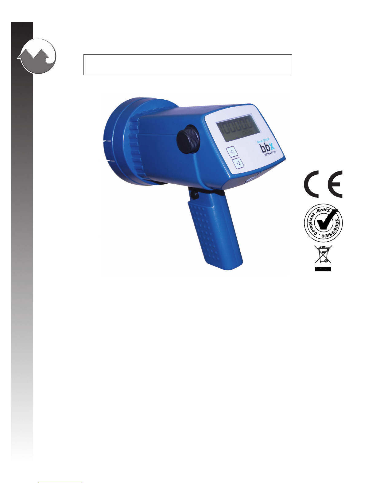
Nova-Strobe bbx
Portable Stroboscopes
Stroboscopes portables
Estroboscopios Portátiles
MONARCH INSTRUMENT
Instruction Manual
(Nova-Strobe bbx
shown / montré /
mostrado)
www.GlobalTestSupply.com
Find Quality Products Online at: sales@GlobalTestSupply.com
Page 2
Safeguards and Precautions
LA DECLARACION DE Ce DE LA CONFORMIDAD
Cuando Fabrica:
Monarch Instrument
La división del Monarch International Inc.
15 Columbia Drive, Amherst NH 03031 USA
declara bajo el Monarch’s única responsabilidad que el product:
a que esta declaración relaciona está en la conformidad con los estándares siguientes:
y por lo tanto se conforma con los requisitos del Concilio Directivo 2004/108/EG
que relaciona la compatibilidad electromagnéticos y 2006/95/EC que relaciona a la
directiva baja del voltaje cuando operado de acuerdo con la guía de usuario. EMC
que prueba de este producto fue realizado por Retlif Testing Laboratories, NH (el
Archivo R-4702N-5).
Nombre: Serie Nova-Strobe X
Modelo: bbx, dbx, pbx, vbx
EN61326:1997 EMC /A1:1998/A2:2001/A3:2003 La Clase A
Específicamente CISPR 16-1:2003/CISPR 16-2:2003
EN55011:1998/A1:1999/A2:2002 EN61000-4-2 EN61000-4-3
EN61010-1:2001-2 Norma de Seguridad
1. Read and follow all instructions in this manual carefully, and
retain this manual for future reference.
2. Do not use this instrument in any manner inconsistent with
these operating instructions or under any conditions that
exceed the environmental specifications stated.
3. Certain strobe frequencies can trigger epileptic seizures in
those prone to that type of attack.
4. Users should not stare directly at the light source.
5. Prolonged exposure to the light can cause headaches in some
people.
6. Objects viewed with this product may appear to be stationary
when in fact they are moving at high speeds. Always keep a
safe distance from moving machinery and do no touch the
target.
7. There are lethal voltages present inside this product. Refer to
the section on Lamp Replacement before attempting to open
this product.
AC Stroboscopes that have three wire mains cable must
have the earth wire connected to a suitable Earth point.
8. Do not allow liquids or metallic objects to enter the ventilation
9. Do not allow cables extending from unit to come into contact
holes on the stroboscope as this may cause permanent
damage and void the warranty.
with rotating machinery, as serious damage to the equipment,
or severe personal injury or death may occur as a result.
Find Quality Products Online at: sales@GlobalTestSupply.com
www.GlobalTestSupply.com
Page 3

TABLE OF CONTENTS
TABLE OF CONTENTS
1.0 OVERVIEW ..........................................................................E-1
1.1 Display Panel / Definition of Buttons ........................E-1
2.0 PREPARA TION FOR USE ..................................................... E-2
2.1 Power.........................................................................E-2
3.0 OPERATION.........................................................................E-2
3.1 Power Up Features ...................................................E-3
4.0 USING THE STROBOSCOPE TO MEASURE RPM ...............E-4
5.0 LAMP AND FUSE REPLACEMENT ......................................E-6
5.1 Lamp Replacement ................................................... E-6
5.2 Fuse Replacement ....................................................E-7
6.0 BA TTERY POWERED MODELS ONL Y .................................E-8
6.1 Low Battery Indication ..............................................E-9
6.2 Charging the Batteries..............................................E-9
6.3 Battery Disposal ......................................................E-10
7.0 SPECIFICATIONS............................................................... E-1 1
8.0 OPTIONS AND ACCESSORIES .........................................E-13
Find Quality Products Online at: sales@GlobalTestSupply.com
www.GlobalTestSupply.com
Page 4
E-1
1.0 OVERVIEW
All descriptions in this manual apply to both the “basic” battery powered
(bbx) and “basic” AC mains powered (bax) digital stroboscopes except
where noted.
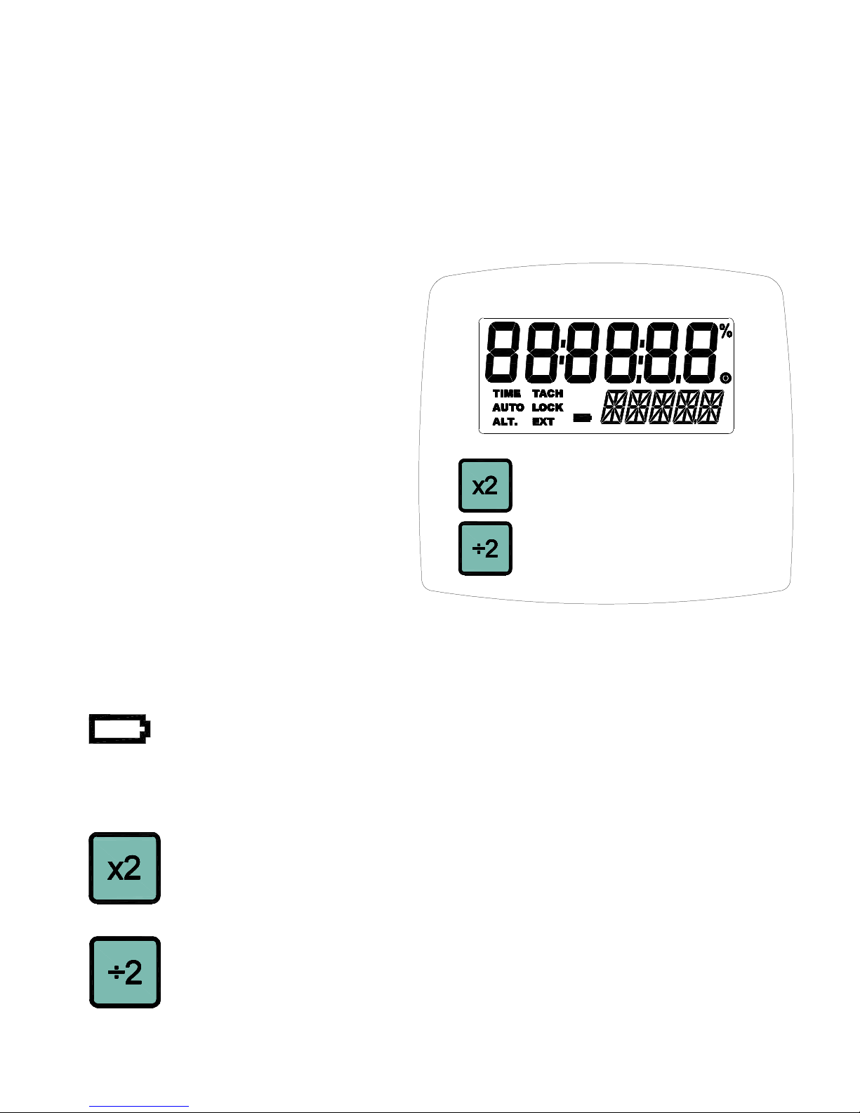
1.1 Display Panel / Definition of Buttons
The display panel consists of
a backlighted liquid crystal
display with six numeric
digits on top and five
alphanumeric digits on the
bottom, which indicate
modes, flash rates, etc. (see
Figure 1).
Additional information
displayed include:
- - - - - Indicates input
frequency exceeds
the limit of the
stroboscope
(Battery Powered Model Only) Battery indication, see
section 6.0
Below the display are two membrane buttons:
Multiplies flash rate by 2 times
Hold when powering up to show all segments, then Rev #
and display test
Divides flash rate by 2
Hold when powering up to reset factory defaults
Figure 1 Display Panel
www.GlobalTestSupply.com
Find Quality Products Online at: sales@GlobalTestSupply.com
Page 5

4.0 USING THE STROBOSCOPE TO MEASURE
RPM
The primary use for a stroboscope is to stop motion for diagnostic inspection
purposes. However the stroboscope can be used to measure speed (in
RPM / RPS). In order to do this several factors need to be considered. First,
the object being measured should be visible for all 360° of rotation (e.g. The
end of a shaft). Second, the object should have some unique part on it, like
a bolt, key way or imperfection to use as a reference point. If the object
being viewed is perfectly symmetrical, then the user needs to mark the
object with a piece of tape or paint in a single location to be used as a
reference point. Look only at the reference point.
If the speed of rotation is within the range of the stroboscope, start at the
highest flash rate and adjust the flash rate down. At some point you will
stop the motion with only a single reference point of the object in view.
Note that at a flash rate twice the actual speed of the image you will see two
images (reference points). As you approach the correct speed you may see
three, four or more images at harmonics of the actual speed. The first
SINGLE image you see is the true speed. To confirm the true speed, note
the reading and adjust the stroboscope to exactly half this reading, or just
press the ÷2 button. You should again see a single image (which may be
phase shifted with respect to the first image seen).
For example, when viewing a shaft with a single key way you will see one
stationary image of the key way at the actual speed and at 1/2,1/3,1/4, etc,
of the actual speed. You will see 2 images of the key way at 2 times the
actual speed, 3 key way at 3 times, etc. The Flashes Per Minute (FPM)
equals the shaft’s Revolutions Per Minute (RPM) at the highest flash
rate that gives only one stationary image of the key way.
E-4
Find Quality Products Online at: sales@GlobalTestSupply.com
www.GlobalTestSupply.com
Page 6

Stopped Image 1/4 times 1/2 times 1 time 2 times 3 times 4 times
Flash Rate (FPM) 833 1250 2500 5000 7500 10000
Example: object rotating at 2500 RPM
If the speed is outside the full scale range of the stroboscope (10,000 FPM),
it can be measured using the method of harmonics and multipoint calculation.
Start at the highest flash rate and adjust the flash rate down. You will
encounter multiple images so be aware of these. Note the flash rate of the
first SINGLE image you encounter, call this speed “A”. Continue decreasing
the flash rate until you encounter a second SINGLE image. Note this speed
as “B”. Continue decreasing the speed until you reach a third SINGLE
image at speed “C”.
For a two point calculation the actual speed is given by:
RPM = AB/(A-B)
For a three point calculation:
RPM = 2XY(X+Y)/(X-Y)2 where
X = (A-B) and
Y = (B-C)
In instances when you can shut down the device and install a piece of
reflective tape, then an optical tachometer is easier to use for RPM
measurement. Stroboscopes must be used when you can’t shut down
the device. The human eye is not easily tricked into seeing a stopped image
by a stroboscope when the flash rate is slower than 300 FPM. Therefore,
stroboscopes are just about impossible to use below 300 FPM for inspection
or to measure RPM.
E-5
Find Quality Products Online at: sales@GlobalTestSupply.com
www.GlobalTestSupply.com
Page 7

5.0 LAMP AND FUSE REPLACEMENT
5.1 Lamp Replacement
WARNING: Before attempting to remove the lamp, make
sure the stroboscope is turned off and any
mains cord is removed from the AC outlet. Allow
the lamp to cool waiting at least 5 minutes.
The stroboscope is designed to discharge the internal high voltages
within 30 seconds. However, caution should be exercised when replacing
the lamp.
The lamp can be replaced by using just a pocket screwdriver . It is not
necessary to remove any screws to replace the lamp.
To change the lamp:
1. Push apart the two tabs on the side of the reflector housing and
remove the lens using a small screwdriver to help pry one tab and
lift the lens. T ake care not to pry the tab any more than is necessary
to free the lens. The reflector is held in place by the front lens and
will come loose, but it is not necessary to remove the reflector.
2. Hold the lamp with a cloth between your forefinger and thumb
and rock it back and forth gently while pulling out. Do not attempt
to rotate the lamp. The lamp is socketed and will come out easily
when pulled straight out.
W ARNING: Do NOT touch the new lamp with bare fingers.
3. The lamps are polarized and must be put into the socket matching
polarity . Using a lint free cloth, match up the red dot on the
plug with the red dot on the socket and gently rock the lamp
E-6 S-7
Page 8

E-7
while pushing it into place (see Figure 4). Make sure the lamp is
in straight and centered in the reflector hole.
CAUTION: Do NOT allow the reflector to contact the lamp.
4. Reinstall the reflector and then position the front lens in place
matching up the notches on the lens with the two small tabs on
the housing to prevent lens rotation (see Figure 2). Push the tabs
on the front rim outward and press the lens into place.
5.2 Fuse Replacement
Under normal operating conditions, the fuse within the stroboscope
should never blow . Examples of abnormal operating conditions would
be foreign materials entering the strobe, such as water, pulp, ink, etc.
Figure 4 Lamp Replacement
Red Dots
Notches
www.GlobalTestSupply.com
Find Quality Products Online at: sales@GlobalTestSupply.com
Page 9

The AC Powered stroboscope has a replaceable fuse inside the unit,
which may be accessed by removing the lens and reflector - refer to
Figure 2. If the fuse needs to be replaced, replace only with a fuse of
the same type and value: Fast Blow - 750mA, 2AG.
W ARNING: Before attempting to replace the fuse, make
sure the stroboscope is turned off and any
mains cord is removed from the AC outlet. Allow
the lamp to cool waiting at least 5 minutes.
The Battery Powered stroboscope has a resettable fuse, which will
reset once conditions are normal again.
6.0 BA TTER Y POWERED MODELS ONLY
The Nova-Strobe bbx is fitted with rechargeable NiMH (Nickel Metal
Hydride) batteries. These batteries contain fewer toxic metals than NiCd
(Nickel Cadmium) and are currently classified “environmentally friendly”.
They also have 30% more capacity than NiCd batteries of the same size.
Like NiCds, NiMH batteries are prone to self-discharge - 10 to 15% of
charge is lost in the first 24 hours then continues at a rate of 0.5 to 1% per
day. For maximum performance, charge the batteries just prior to use.
When not in use, the batteries should be charged at least every three months,
otherwise the battery capacity will be reduced or the batteries may become
unusable.
Charge the batteries before use and allow 3-5 cycles of charging and
discharging for batteries to reach full capacity.
The enclosure contains control electronics to properly and safely charge the
batteries. Never remove the batteries from the enclosure and attempt to
charge externally. Always use the charger supplied (PSC-2U).
E-8
Find Quality Products Online at: sales@GlobalTestSupply.com
www.GlobalTestSupply.com
Page 10

E-9
6.1 Low Battery Indication
When the batteries are charged, there will be no battery indication.
When the batteries are low, the Low Battery icon will blink in the
display. The strobe may still be used for a short time.
Low Battery Icon = Outline blinking (very little time left)
The strobe has a protection feature that prevents the strobe from
operating if the battery voltage is too low . This condition is indicated
by no flash and the display shows “LO BAT”. At this time the
batteries must be recharged. Remember to release the trigger switch.
6.2 Charging the Batteries
The unit may be recharged at any time. You do not need to wait until
the low battery condition is indicated.
To charge the battery powered strobe with the recharger:
1. Release the trigger so the strobe is off.
2. Plug the recharger cable into the recharger socket (located below
the display panel behind the handle).
3. Plug the recharger into an AC mains wall outlet (115/230 Vac).
CAUTION: Use of rechargers other than the one supplied
(PSC-2U) will damage the stroboscope and void
the warranty.
When the recharger plug is inserted into the recharger jack, the strobe
will go into the Charging Mode. Make sure the trigger switch is not
depressed. The strobe will not do anything else when charging (e.g. it
will not flash and the buttons have no function).
www.GlobalTestSupply.com
Find Quality Products Online at: sales@GlobalTestSupply.com
Page 11

When charging, the strobe will indicate CHRGE in the bottom right of the
display . The recharger will fast charge the batteries for about 4-5
hours and then trickle charge the batteries.
Allow the recharger to charge the batteries until the display shows
DONE for peak battery life performance. If the batteries are not charged
to 100% regularly, the batteries will lose capacity.
6.3 Battery Disposal
Prior to disposing of the battery-powered strobe, the user must remove
the Nickel-Metal Hydride batteries. To do this, remove the lens,
reflector and lamp as detailed in the Lamp Replacement section. This
will expose four (4) screws that must be removed so the reflector
housing can be dismantled. There are four (4) additional screws in the
case half opposite the input and output jacks that must be removed.
The case halves can now be separated, exposing the batteries. Remove
the cables from the batteries and place tape over the battery terminals
to prevent them from shorting. The batteries should be sent to a
recycling center or returned to the factory. The rest of the parts may
now be disposed of.
E-10
Find Quality Products Online at: sales@GlobalTestSupply.com
www.GlobalTestSupply.com
Page 12

7.0 SPECIFICATIONS
Internal Mode:
Flash Range 30 - 10,000 FPM (Flashes Per Minute)
Flash Rate Accuracy ±1 FPM
Flash Rate Resolution 1 FPM
Display Update Rate Instantaneous
Time Base Ultra Stable Crystal Oscillator
Display LCD display with 6 numeric 0.506 inch
[12.85 mm] high digits and
5 alphanumeric 0.282 inch [7.17 mm] high
digits
Indicators Battery level
Knob Adjustment Digital Rotary switch with 36 detents per
revolution; velocity sensitive
Memory Last setting before power down is remembered
and restored on next power up
Flash Duration 10-25 microseconds (auto adjust with flash
rate)
Flash Tube (Lamp) Life 100 million flashes
This product is designed to be safe for indoor use under the following
conditions (per IEC61010-1).
Operating Temperature 32-104 ºF [0-40 °C] (May be operated for short
time periods, slightly beyond stated temperature
range)
NOTE: Safety thermal feature will set unit into TACH Mode (stops
flashing) in the event of internal overheating. Unit must
then be power cycled.
Humidity Maximum relative humidity 80% for temperature
up to 88 °F [31 °C] decreasing linearly to 50%
relative humidity at 104 °F [40 °C]
E-1 1
Find Quality Products Online at: sales@GlobalTestSupply.com
www.GlobalTestSupply.com
Page 13

E-12
bbx Specific:
Input Power Battery powered: Internal Rechargeable
Batteries 6 Vdc, External AC recharger (100 V ac
to 240 Vac, 50/60 Hz)
Light Output Average: 13 Watts typical > 4000 FPM
Instantaneous (per flash): 230 mJoule typical
to 4000 FPM
Run Time 2 hours typical at 1800 FPM, and over 1 hour at
6000 FPM with fully charged batteries
Charge Time 4-5 hours typical with PSC-2U
Weight 1.875 lbs [0.8505 kg] including batteries
bax Specific:
Input Power AC powered: 115 Vac OR 230 Vac, 35VA (as
ordered)
Light Output Average Power: 15.5 Watts typical > 4000 FPM
Instantaneous (per flash): 230 mJoule typical
to 4000 FPM
Run Time Continuous within temperature limitations.
Vents must not be restricted. Unit must be
horizontal.
Weight 1.55 lbs [0.70 kg]
 Loading...