

Page 1
Instruction Manual
MONARCH INSTRUMENT
Printed in the U.S.A.
Copyright 2011 Monarch Instrument, all rights reserved
1071-8309-112R
0411
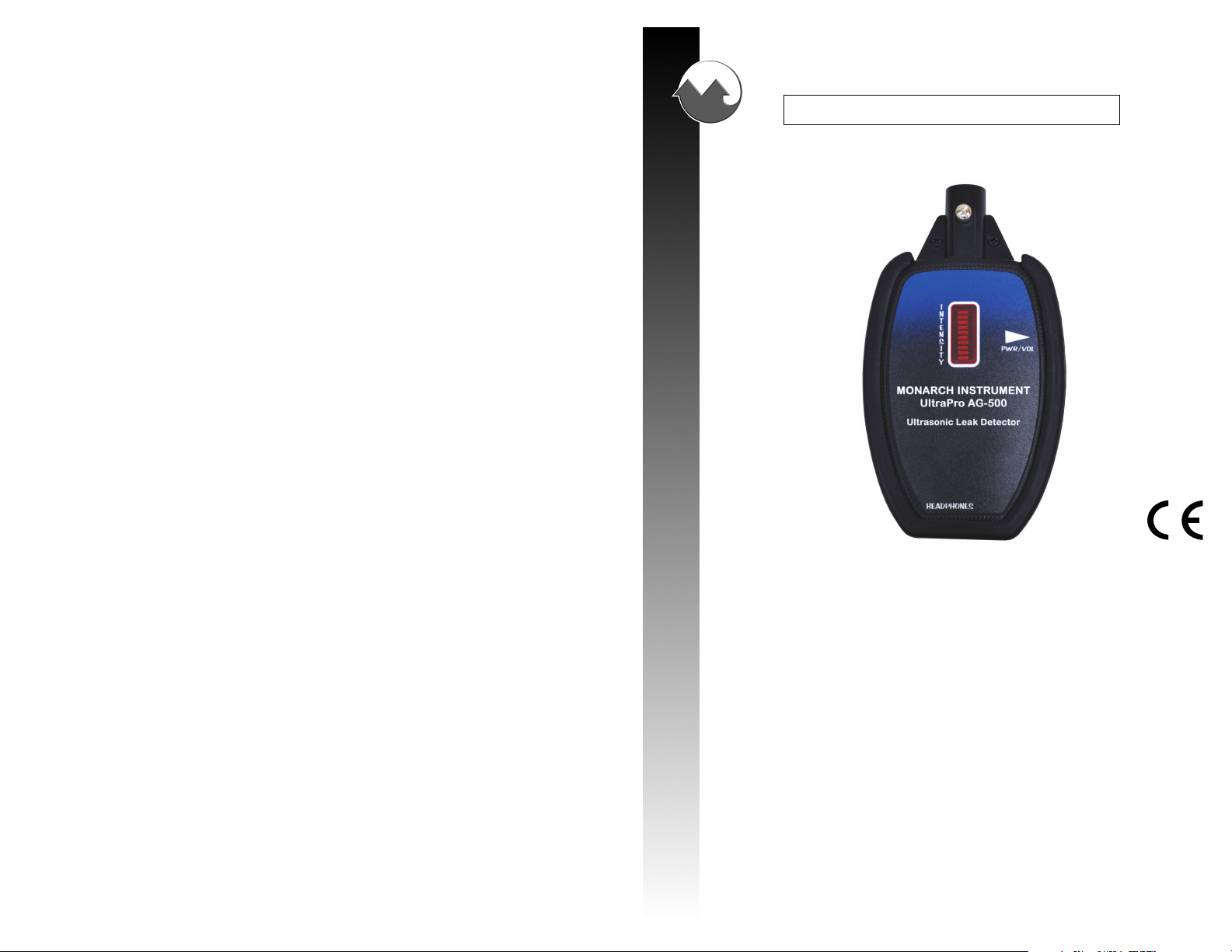
Monarch UltraPro AG-500
Ultrasonic Leak Detector
15 Columbia Drive
Amherst, NH 03031 USA
Phone: (603) 883-3390
Fax: (603) 886-3300
E-mail: support@monarchinstrument.com
Website: www.monarchinstrument.com
Page 2

TABLE OF CONTENTS
TABLE OF CONTENTS
General Principal of Operation ................................................................. 1
General Applications ................................................................................ 1
Why Use Ultrasonic Listening Devices? ................................................... 1
UltraPro AG-500 OVERVIEW .................................................................. 2
The UltraPro AG-500 System................................................................... 2
UltraPro AG-500 Receiver ........................................................................ 2
Probes ..................................................................................................... 3
Tone Generator ........................................................................................ 3
Receiver and Tone Generator Guidelines .................................................. 3
Batteries and Replacement ...................................................................... 3
Calibration ............................................................................................... 3
OPERATING INSTRUCTIONS
Using Air or Contact Probes
The air and contact probes are used to optimize the response depending on the type of inspection.
The air probe is best used for detecting ultrasounds associated with a pressure leak or an
electrical corona. The contact probe is best used to detect the ultrasounds generated from within
a casing such as in a gear, bearing, pump, solenoid, valve, or steam trap housing.
Specific Applications
For air/gas and electrical leaks - Use receiver with black air probe for better pinpointing of leaks.
A leak is very directional and sounds like a rushing sound. Scan side to side as you walk toward the
increasing sound (suspected leak). You should decrease volume as the sound increases to reduce
fatigue.
For analyzing internal sounds - such as for mechanical bearings, gears, rotors, or turbulence in
pneumatics, steam valves, and solenoids or electrical discharge like in top over coils. Attach the
contact probe making sure it is seated in the nose of the receiver with the thumbscrew firmly screwed
down. Hold tip of probe to appropriate areas while equipment is running. For a wheel bearing,
safely jack car and touch stationary hub while turning wheel by hand.
For analyzing non-pressurized vessels - such as for windshield/door leak. Turn Tone Generator
on and position in vehicle with nose pointing toward suspect area. Close all openings such as doors,
windows, etc. and walk around exterior with the receiver. Listen for increased and decreased sounds
from the Tone Generator leaking through cracks and voids in gaskets, etc.
Safety Precautions .................................................................................. 4
Basic Operational Procedures ................................................................. 4
Scanning Techniques ............................................................................... 4
Using LED Graph on Receiver and/or Headphones ............................ 4
Using Air or Contact Probes .............................................................. 5
Specific Applications ................................................................................ 5
TECHNICAL SPECIFICATIONS ............................................................... 5
Warranty Information ................................................................................ 5
SAFEGUARDS AND PRECAUTIONS
Read and follow all instructions in this manual carefully, and retain this manual
for future reference.
Do not use this instrument in any manner inconsistent with these operating instructions
or under any conditions that exceed the environmental specifications stated.
This instrument is not user serviceable. For technical assistance, contact the sales
organization from which you purchased the product.
In order to comply with EU Directive 2002/96/EC on Waste Electrical and Electronic
Equipment (WEEE): This product may contain material which could be hazardous to
human health and the environment. DO NOT DISPOSE of this product as unsorted municipal
waste. This product needs to be RECYCLED in accordance with local regulations,
contact your local authorities for more information. This product may be returnable to
your distributor for recycling - contact the distributor for details.
TECHNICAL SPECIFICATIONS
Circuitry: Solid State - no calibration required
Frequency Response: 44 kHz Centered
Power Requirement: Standard 9-Volt
Battery Life: Approx. 15 hours
Power Consumption: 30 mA, typical
Headphone Connector: 3.5mm phone plug
Housing: Chemical Resistant ABS with Protective rubber boot
Dimensions: Receiver: Width: 4.0” [10.2 cm], Depth: 1.0” [2.5 cm], Length: 6.0”
[15.2 cm]
Tone Generator: Width: 1.5” [3.8 cm], Depth: 1.25” [3.2 cm], Length:
5.0” [12.7 cm]
Weight: UltraPro Receiver: 8 oz [226.8 g], System: 1.7 lbs [771.1 g]
Operating Temp. Range: 50 to 140 °F [10 to 60 °C]
Warranty Information
Monarch Instrument’s Limited Warranty applies. See www.monarchinstrument.com
for details.
Warranty Registration and Extended Warranty coverage available online at
www.monarchinstrument.com.
5
Page 3

OPERATING INSTRUCTIONS
Safety Precautions
While the UltraPro AG-500 allows you to focus on diagnosing a problem in a fast and effective
manner, never lose awarness of your surroundings.
• The UltraPro AG-500 and probes are an extension of your hand. Keep a safe distance from
moving parts and electrical areas.
• Never over reach or de-stabilize your footing while using the UltraPro AG-500.
• Always be aware of the headphone cord when near moving parts.
• Never use the air or contact probes as a lever, pry bar, or for other unintended purposes.
• Never use the contact probe for diagnosing electrical problems.
Basic Operational Procedures
Note: Please read all safety precautions above before proceeding.
The UltraPro AG-500 ultrasonic detector is simple to use. No Calibration or training is required.
Use the following steps:
1. Plug the headphones into the jack on the bottom of the Receiver. Do not place the
headphones on before you turn on the power.
2. Select the air or contact probe as needed (see Using Air or Contact Probes section).
3. Turn the rotary knob clockwise to “on” and watch for the LED bar to settle to the bottom
position.
4. Place the headphones on and adjust the volume until you can just hear the background
noise (hiss). Please note that increasing the volume does not increase the unit’s detection
sensitivity. Setting the volume control too high can lead to operator fatigue.
5. When using the air probe, point the probe in the direction of your free hand while lightly
rubbing your forefinger and thumb together 2+ feet away. The response should be the
sound of sandpaper on wood. You can vary the distance and increase/decrease the level of
volume accordingly. While performing this test, familiarize yourself with the directional
sensitivity of the probe while sweeping the probe past your fingers at various distances.
6. When using the contact probe, adjust the sensitivity while lightly rubbing your finger along
the tip of the rod.
Scanning Techniques
Using LED Graph on Receiver and/or HeadphonesFor Locating Leaks
Depending on the amount of ultrasonic signature being detected, use either the level of intensity
on the LED graph and/or the audible amount of sound through the headphones. As you get
closer to the problem decrease the volume. As the sound gets louder, repeat the process until
you have pinpointed the location. Please note that the volume control is independent of the bar
graph intensity during an inspection. With minute leaks, the LED bar graph may not move up
from the first position. In this situation, use the audible signal as discussed above.
4
General Principal of Operation
The UltraPro AG-500 operates on the principle of detecting high frequency ultrasonic waves that are
created by turbulence or friction from all moving parts, liquids and gases. These ”sounds” reside far above
the range of the human ear and tend to be highly directional. This directional aspect of ultrasonic waves
allows one to isolate a suspect signature sound from other background noises and detect its exact location.
Ultrasonic leak detection is very useful in preventive maintenance, trouble-shooting, quality control and
diagnostics in the automotive, industrial, manufacturing and process industries.
General Applications
1. Air/Vacuum Leaks Both vacuum and compressed air leaks create an energy packet or
wave front, which can result in an ultrasonic emission with a
differential of 1 psi and/or a hole down to 0.005”.
2. Gas and liquid turbulence Turbulence associated with internal/external valve leaks, cavitation,
and blockages in liquid and air/gas lines.
3. Electrical discharge Electrical discharge associated with insulation breakdown, tracking,
corona, and arcing.
4. Mechanical wear Condition of mechanical wear in bearings, injectors, valves and
race assemblies, shafts, and gears. Also accurate indication of
proper lubrication in anti-friction bearings.
5. Sound generation Can be used in conjunction with Tone Generators to detect
container cracks and leaks in seals, window/door seals and tanks.
(The Tone Generator is matched to UltraPro peak response.)
Why Use Ultrasonic Listening Devices?
The human ear only hears about 1/3 of the existing spectrum of sound. Actually most of us are
capable of detecting nothing above the 12,000 to 14,000 cycles per second level, depending upon age
and other factors. Ultrasound is in the 20,000 to 43,000 cycles per second range. For a leak to happen
there must be an opening in the system that carries a gas or fluid. As the hole is rarely uniform, the
jagged edges cause the escaping liquid or gas into random circular motions or turbulence. This
turbulence is what the UltraPro detects. It is commonly known that faults, malfunctions, and/or
flaws in mechanical, electrical, and pneumatic devices, as well as manufactured container type
objects, start as small defects or leaks. The physical size of these defects is of such relatively small
size the sounds that they produce are above the range of human hearing and are not detectable aurally.
Since these sounds are above the normal level of hearing, the UltraPro AG-500 is required to
transform or convert the ultrasound to an audible level. The UltraPro AG-500 incorporates a process
whereby the audible signal bears a close likeness to the natural incoming sample. We call this process
“Sound Signature Technology”; the result is a gas leak sounds like a “hiss” and a defective bearing
sounds like a “clicking or chatter”.
The UltraPro AG-500 uses a technology called heterodyning to convert the ultrasonic range into the
audible range. Since this unit is tuned to listen to the ultrasonic range, it is unaffected by everyday
sounds such as wind, voices, and traffic which can further mask the technician’s ability to listen for
a potential problem. The UltraPro AG-500 also incorporates AGC (Automatic Gain Control),
which allows one to study ultrasonic sounds associated with the roar of a valve leak or literally the
blink of an eye. AGC stops the need for high/low sensitivity switches by allowing the internal
circuitry to seek the optimum level of gain for the given situation. This allows the UltraPro AG-500
total ease-of-use and immediate application without having to fiddle with knobs or seeking correct
settings. The UltraPro AG-500 was designed to be extremely effective yet easy to use, allowing the
technician to concentrate on analyzing the problem and not on the operation of the instrument.
1
Page 4

UltraPro AG-500 OVERVIEW
The UltraPro AG-500 is a unique diagnostic test instrument that has achieved outstanding results in
reducing downtime and maintenance related costs. Through the detection of ultrasonic sound, the
UltraPro AG-500 is used to inspect and check such items as ignition systems, vacuum problems, air
brake systems, bearings, gear trains, cam and tappet assemblies, internal combustion engine valving
and piston blow-by, gaseous piping and ducting, seals in refrigerated van bodies, air ducts, hydraulic
systems, Freon leaks, and many other components.
The UltraPro AG-500 System consists of an ultrasound receiver, ultrasound tone generator, air
probe, contact probe and headphones. The receiver is sensitive only to ultrasonic energy in the
frequency range of 36,000 to 44,000 Hz. The energy is amplified by internal circuitry and converted
to audible sounds, available through the headphones, and an intensity reading on the red LED
display. The ultrasonic receiver is used with the tone generator to check for faulty seals in nonpressurized enclosures like automotive cabin windows/doors/roofs, etc. It is fast and easy to use and
takes very little training! The tone generator “fills the item being tested with noise” for the receiver
to detect at the leak source.
Probes
Both the air and contact probes are precision parts, designed to optimize the response of the
UltraPro AG-500 Receiver when needed. The 12” air probe serves to extend reach or to facilitate in
isolating a leak among multiple suspect areas. The contact probe is supplied with a rubber groment
which should be installed 0.25” from the threaded cap end. Do not modify the probes in any way and
never use the probes for anything other than described in this manual.
Tone Generator
The Tone Generator emits a warble output centered at 40kHz for use in testing seal
integrity in non-pressurized vessels. The human ear cannot hear this output, so the Tone
Generator must be used with the UltraPro AG-500 Receiver and headphones. The Tone
Generator is powered by (1) 9-Volt battery, and can operate up to 40 feet [12 m] to
locate leaks. If the red indicator on the Tone Generator is on, the unit is emitting noise.
Verify operation with the receiver.
The UltraPro AG-500 System
1. UltraPro AG-500 Receiver
5
2. Tone Generator
3. Two Probes: 12” air probe and a precision
6
length contact probe
4. Two Headphone sets: high-fidelity
4
1
microbuds (shipped in case pocket) and
over-ear headphones
5. Padded carrying case
4
2
3
6. Two 9-Volt batteries (in case pocket)
UltraPro AG-500 Receiver
The UltraPro AG-500 Receiver is an easy-to-use unit incorporating audio feedback and a 10 bar LED
indicator for visual intensity of signal. The receiver has a permanently fixed 2” directional receiver
port, 3.5 mm stereo jack and a rotary on/off volume control switch. It is powered by (1) 9-Volt
battery.
The LED display allows the user to zero in on a steady state source of ultrasonic sound when
locating a gaseous or vacuum leak or using the tone generator. Simply watch for a rise in the bar levels
as you get closer to the location of the leak/noise source.
Simply use the method described in step 5 under the Basic Operational Procedures to test the
performance of the receiver. If no sound is heard, replace the battery.
Receiver and Tone Generator Guidelines
• The UltraPro AG-500 Receiver and Tone Generator are rugged but still precision instruments.
Avoid rough handling.
• The carrying case should be used whenever possible for protection and transportation.
• The port openings of the Receiver and Tone Generator contain the heart of the UltraPro AG-
500’s operation, a precision transducer/transmitter. During use, guard against any foreign matter
or liquids from entering these areas.
• The Receiver and Tone Generator are not waterproof and should be protected from the elements.
• To prolong battery life, make sure each unit is turned off when not in use.
Batteries and Replacement
Both the UltraPro AG-500 Receiver and Tone Generator use one 9-volt battery each. Alkaline are
required. To replace the battery in the Receiver, the protective rubber boot has to be removed first.
When replacing the Tone Generator battery, be careful not to strain or pinch wires. Always remove
the battery during a period of long storage.
Calibration
The UltraPro AG-500 system has been optimally tuned at the factory and should require no recalibration during its life under normal conditions.
2
3
 Loading...