

Page 1
Monarch is a trademark of Avery Dennison
Retail Information Services LLC.
Avery Dennison is a trademark of Avery Dennison Corp.
TC9906APQR Rev. AD 9/12 2010 Avery Dennison Corp. All rights reserved.
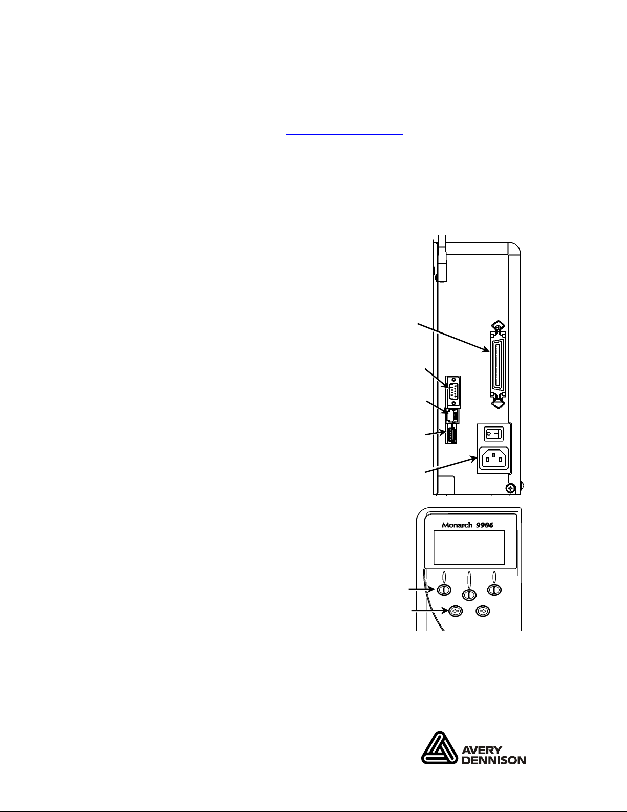
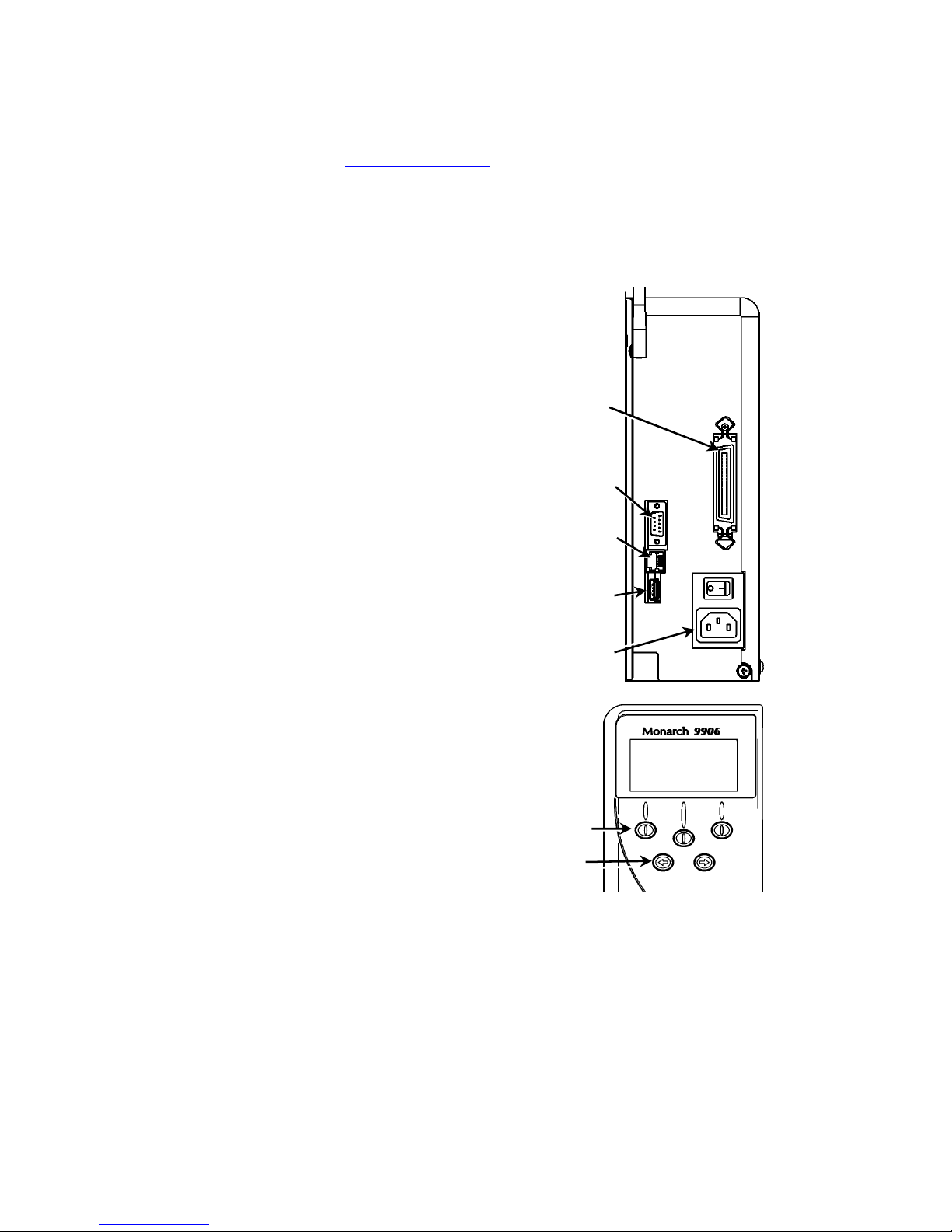
Serial Port
Host USB
Device USB
Power Cable
Connection
Parallel Port
(optional)
QUICK REFERENCE
This Quick Reference contains supply loading and general care
and maintenance procedures for the Monarch® 9906 printer. For
more detailed information, refer to the Operator’s Handbook
available on our Web site (www.monarch.com
). For information
about creating formats, configuring the printer, or programming
the printer, refer to the Packet Reference Manual on our Web
site.
Review the safety information in the Regulatory Compliance
document included with your printer. Information in this
document supercedes information in previous versions. Check
our Web site for the latest documentation and
release information.
Connecting the Cables
The power supply automatically
switches between 115V and 230V.
1. Plug the power cable into the
socket and the other end into
a grounded electrical outlet.
2. Connect the communications
cable into the appropriate port.
3. Turn on the printer. Press ( I )
to turn on and ( O ) to turn off
the printer.
Using the Control Panel
The control panel consists of a fourline LCD display, three function
buttons, and two navigation buttons.
The function of each button varies
depending on the task.
The LCD display:
Indicates power when text or
other information is shown
Indicates conditions requiring
immediate attention (low battery,faults, errors) using a red
background
Shows menu prompts, printer settings, function button
assignments, values, etc.
Function
Buttons
Navigation
Buttons
MPCL
Online
FEED
TLabel MENU
Page 2
2-EN
Printhead Tab
Retaining Latch
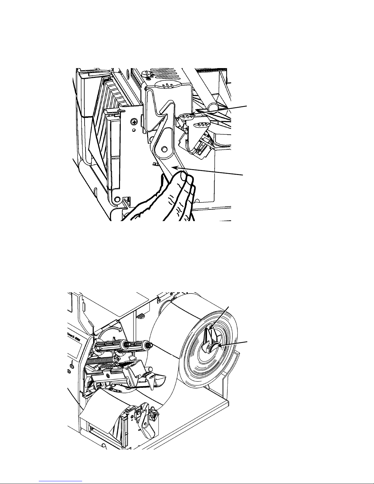
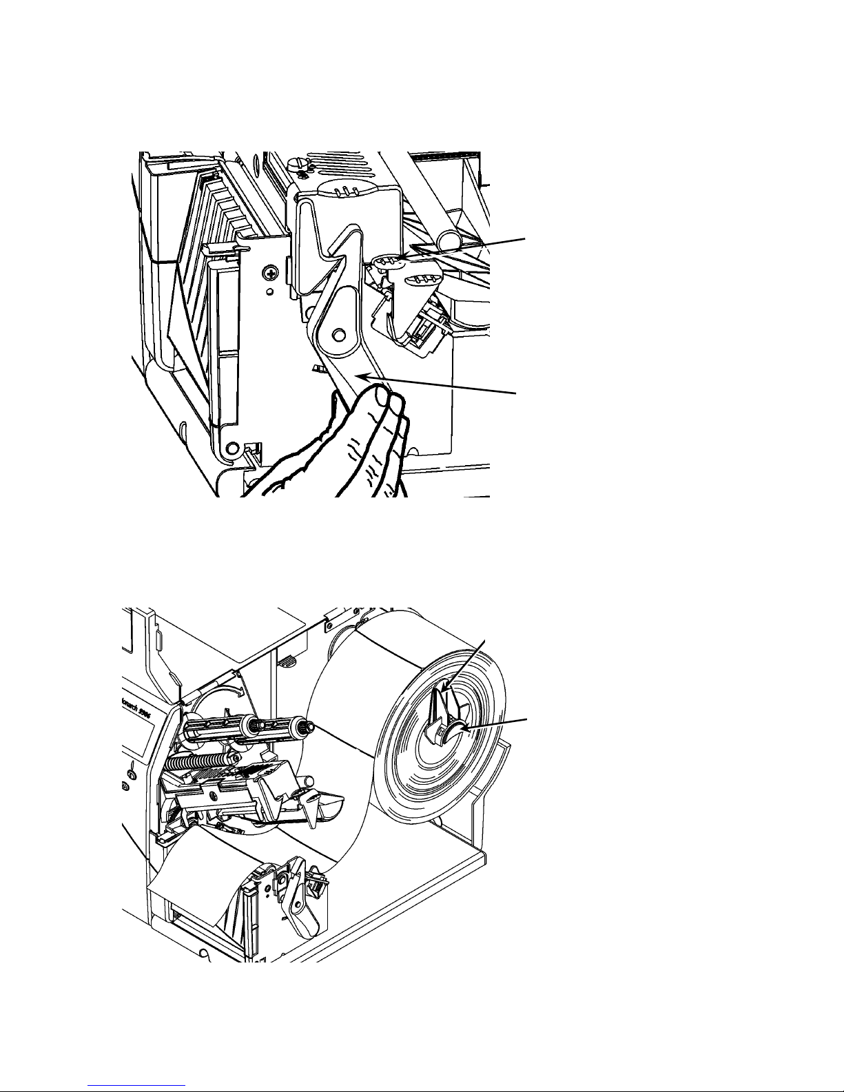
Loading Labels or Tags
1. Open the cover.
2. Unlock the printhead by turning the retaining latch.
3. Lift the printhead assembly using the printhead tab until the
assembly locks into place.
4. Place the roll of supply on the supply holder, located against
the inside of the printer.
5. Adjust the supply holder guide so that it barely touches the
roll, making sure the supply roll turns freely.
Supply Holder Guide
Supply Holder
Page 3
EN-3
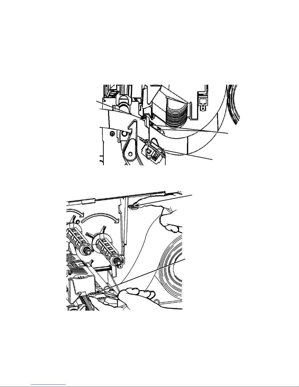
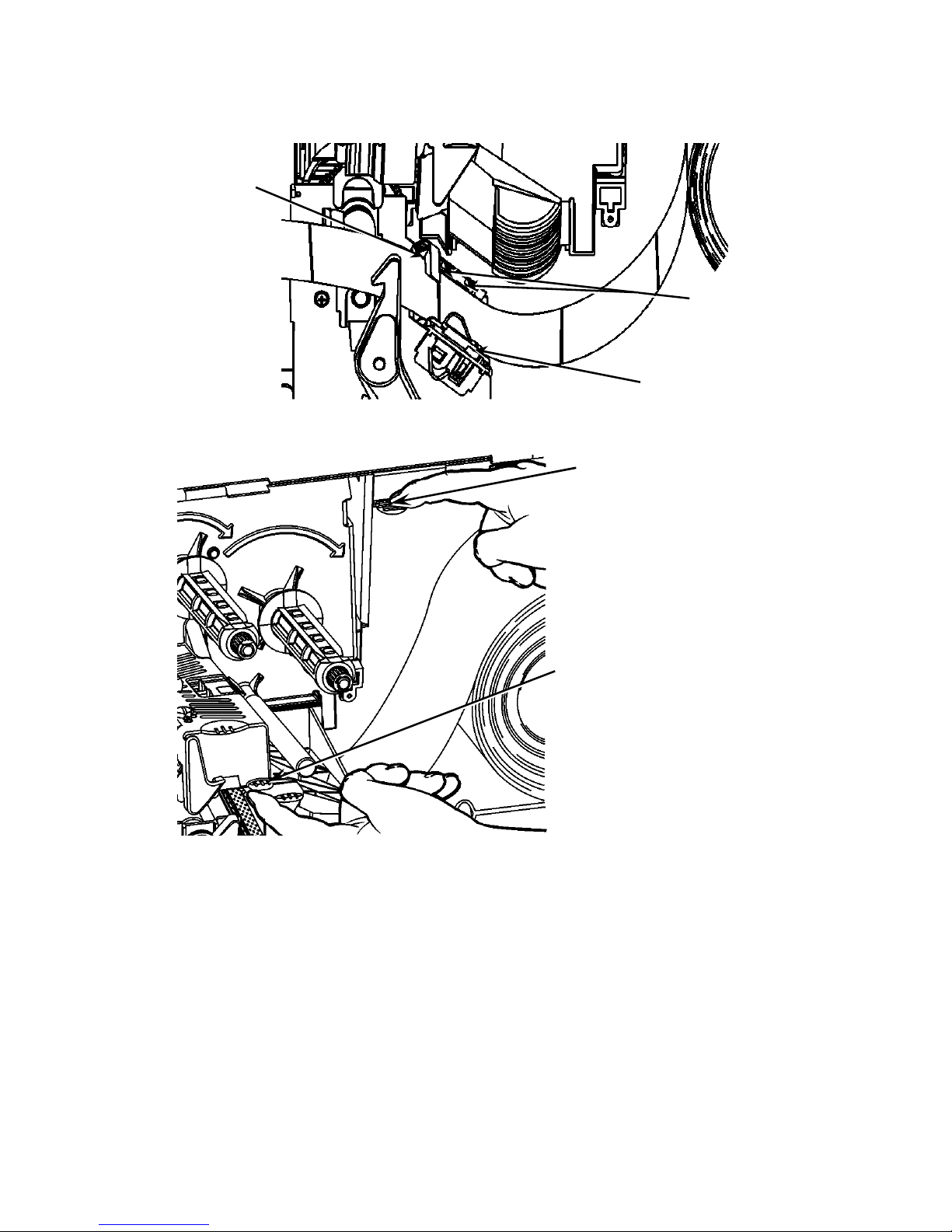
6. Push down on the supply lever to unlock the supply guide.
7. Lay the label strip across the supply guide so that a few
inches extend past the front of the printer.
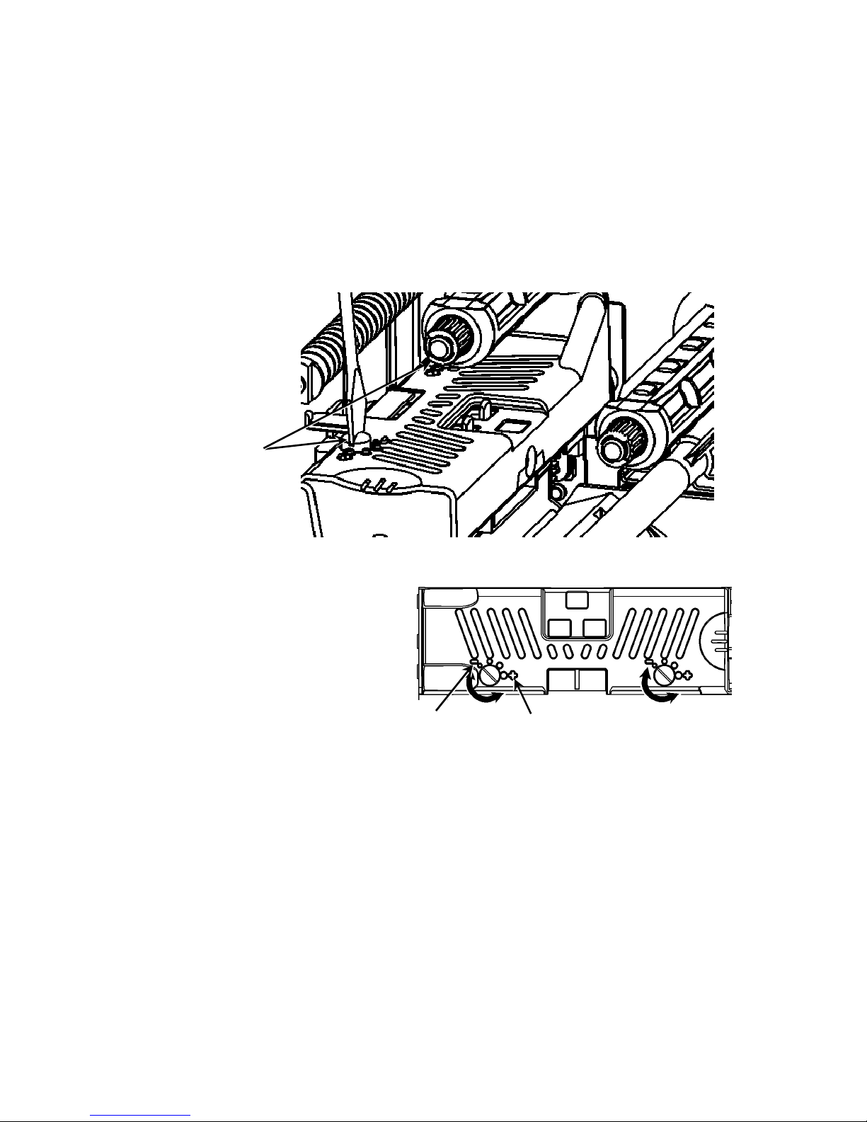
8. Tuck the supply under the nibs and in between the die cut
sensor.
9. Adjust the supply guide so that it barely touches the supply.
Push up on the supply lever to lock the supply guides into
place.
10. Hold the printhead assembly by the printhead tab while
pushing the printhead release.
Printhead Release
Printhead Tab
Supply Lever
Nibs
Die Cut
Sensor
Page 4
4-EN
11. Close the printhead by pressing down on the thumb well until
you hear it click into place.
12. Close the printer’s cover.
13. Press FEED.
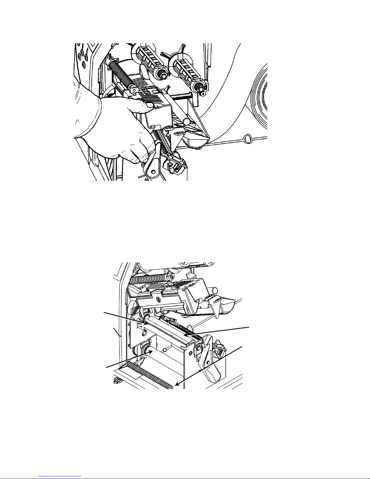
Loading Labels for the Optional Peel Mode
1. Remove the labels from the first 10 inches of the liner.
2. Press down on the exit cover tabs to open the exit cover.
3. Feed the liner over the peel bar, along the chute, and out
through the lower opening in the exit cover.
4. Close the exit cover.
5. Close the printer’s cover.
6. Press FEED.
For additional supply loading options, refer to the Operator’s
Handbook.
Peel Roller
Lower Opening
Platen Roller
Peel Bar
Page 5
EN-5
Adjusting the Printhead Pressure Dials
The default setting is least pressure, which provides optimal
printing in most cases. If you see smudging, ribbon wrinkling, or
poor print quality, you may need to adjust the printhead pressure
dials.
The two dials are located on either edge of the printhead
assembly (inside and outside). The dials may be set to different
positions; however, the inside dial should be equal to or more
pressure than the outside dial. When using 4” wide supply both
knobs should be set at equal pressure. Use a coin or flathead
screwdriver to adjust the dials.
Each dial has four settings:
Least pressure
Light pressure
Medium pressure
Most pressure
Print a test label to check the printhead pressure; make
adjustments as necessary. Refer to the Operator’s Handbook for
additional information.
Loading Ribbon
1. Open the cover.
2. Unlock the printhead by turning the printhead retaining latch.
3. Lift the printhead assembly using the printhead tab until the
assembly locks into place.
Printhead
Pressure Dials
Least
Pressure
Most Pressure
Page 6
6-EN
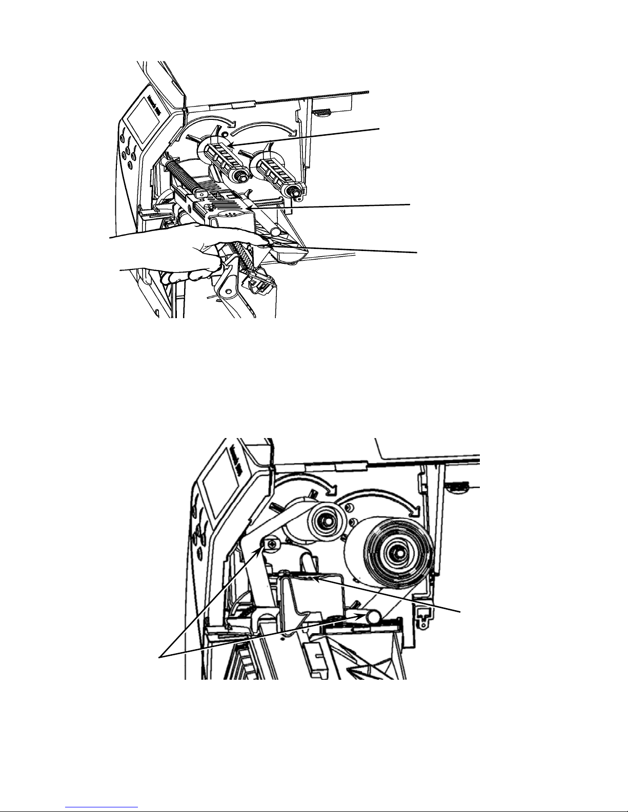
4.
Push the deflector tab down.
5. Slide the extra ribbon core onto the take-up reel as far as it
will go.
6. Remove the new ribbon from the package.
7. Slide the ribbon all the way onto the back reel. Carefully
unwind a few inches from the bottom of the ribbon roll.
8. Feed the ribbon under both ribbon rollers and printhead.
9. Make sure the ribbon is straight and centered throughout the
path.
10. Tape the ribbon to the take-up core.
11. Rotate the take-up core until the leader is past the printhead.
Take-up Reel
Printhead
Assembly
Deflector Tab
Thumb
well
Ribbon
Rollers
Page 7
EN-7
12.
Remove any slack in the ribbon by turning the take-up reel
clockwise.
13. Hold the printhead assembly by the printhead tab while
pressing down on the printhead release.
14. Close the printhead by pressing down on the thumb well until
you hear it click into place.
15. Close the printhead. Close the printer’s cover.
16. Press FEED.
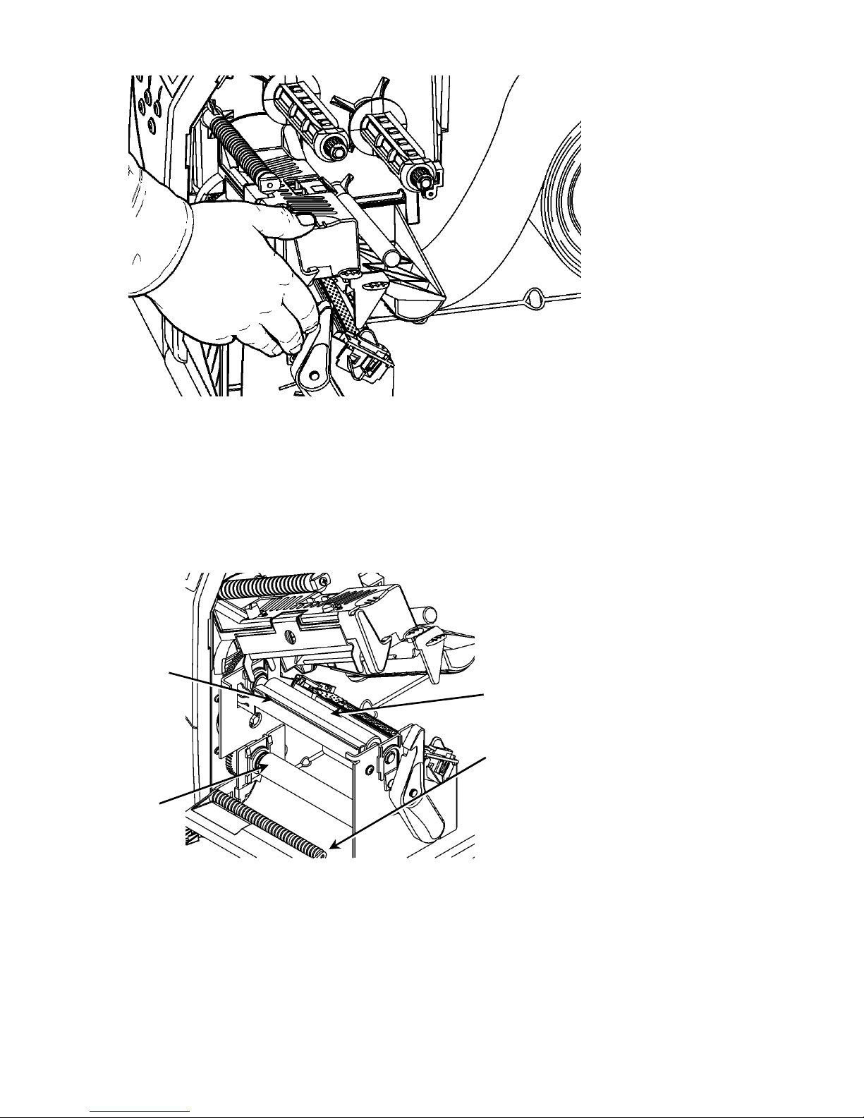
Cleaning
Clean the printhead as described to maintain printhead life.
Caution: Do not use sharp objects to clean the printhead or
touch the printhead; this may damage the printhead
and require a service charge.
1. Turn off the printer, open the cover and the printhead
assembly.
2. Remove the label roll and ribbon (when cleaning the
printhead).
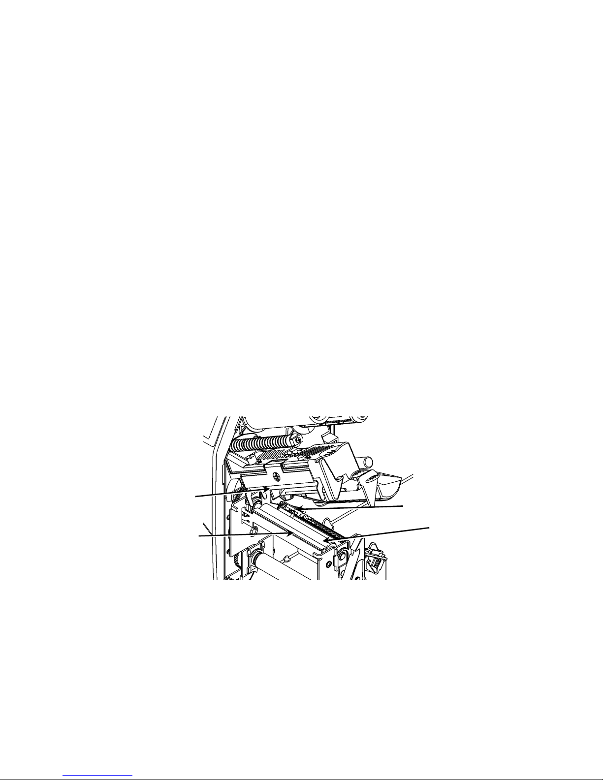
3. Press down on the exit cover tabs to open the exit cover.
4. Spray the supply path, including supply sensor, with
compressed air to remove dust.
5. Use a CLEAN-STRIP (part number 120350) to clean and
remove adhesive build-up from the platen roller, peel bar,
sensor, and printhead.
6. Let the printer dry, then reload supplies.
7. Close the exit cover.
8. Close the printhead assembly and the printer’s cover.
9. Turn on the printer. Press FEED.
Platen Roller
Printhead
Sensor
Peel Bar
Page 8
8-EN
Selecting the Interpreter
The 9906 printer includes four Interpreter options; MPCL, MLI,
WMS XML, and Easy-Plug. For more information about MLI refer
to the MLI Quick Reference, for more information about WMS
XML refer to the XML Quick Reference, for more information
about Easy-Plug refer to the Easy-Plug Manual included on the
CD-ROM.
From the Main Menu, select Setup, then:
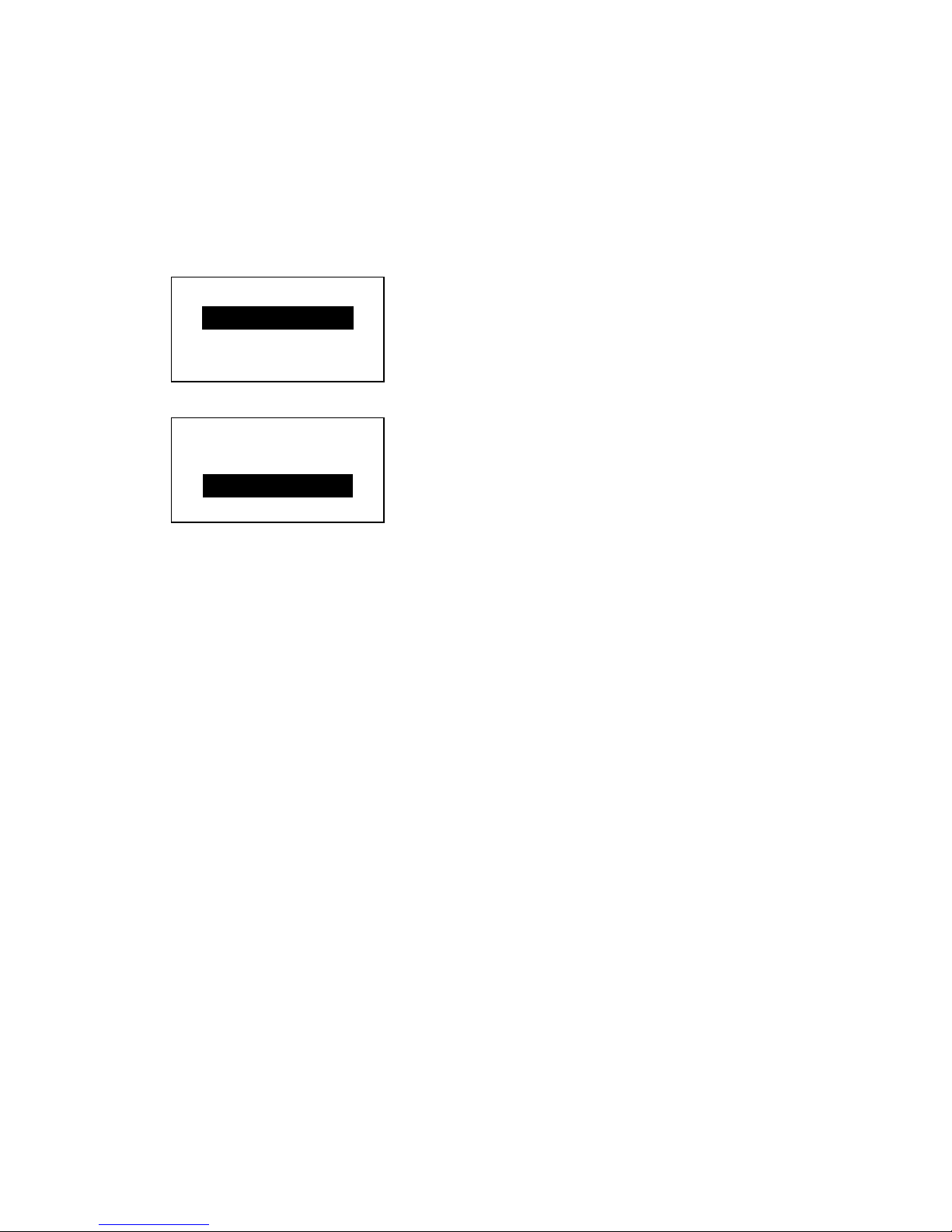
1. Press or until Inter preter is on the display.
SETUP
Interpreter
MPCL
CHANGE BACK
2. Press CHANGE then press until Easy-Plug is on the display.
MAIN MENU
Interpreter
Easy-Plug
SET CANCEL
3. Press SET to save the change.
The printer reboots automatically after selecting an
interpreter. This process may take several seconds.
When you print test labels with MLI set as the interpreter,
the model number appears as M9906MLI.
When you print test labels with Easy-Plug set as the
interpreter, the model number appears as M9906EP.
Page 9
EN-9
RFID (if installed)
The 9906 printer with RFID has been engineered to program
(encode) an RFID (Radio Frequency Identification) label
(commonly called “RFID tags”) before the label’s format is
printed. RFID tags contain an embedded RFID inlay (chip and
antenna).
RFID is only available using die cut or black mark supplies.
The printer supports Class 1 Generation 2 (C1Gen2) protocol
encoding.
RFID supplies can be damaged by static electricity.
Ground yourself by touching metal, such as the
printer’s metal base, before handling the supplies.
The UHF radio operates in the 902 – 928 MHz frequency range
in accordance with FCC Rules and Regulations.
RFID Setup Menu
Use the RFID Setup Menu to Read a tag, set the RF Power, and
Clear Data.
The Read Tag menu item lets you read the EPC data
programmed into an RFID tag.
Refer to the RFID Web Setup Utility at
http://www.servisource1.com/prnutil/rfidsetup
to set the RF
Power setting.
The printer stores the number of successful and failed
programmed tags. Clear this record using the Clear Data menu
item. Depending on your application and volume of labels
printed, you may want to clear this data daily or after each batch.
To access the RFID settings, from the Main Menu select Setup,
then RFID.
If the RFID tag is not programmable for any reason, the label
may print with an overstrike pattern, indicating that it should not
be used. Your System Administrator should set the desired Error
Action accordingly.
If you see RFID errors 740 – 749, see your System
Administrator.
Refer to the Operator’s Handbook and Application Notes for more
information.
SETUP
← RFID →
SELECT BACK
Page 10
10-EN
Troubleshooting
This section lists common problems and their solutions.
Problem Action
Error message
appears during
startup
Turn off the printer, wait fifteen seconds
and then turn on the printer. Call
Customer Service if the error message
reappears.
Does not print.
Check supply and ribbon, send a
corrected format and batch packet.
Does not feed. Adjust the printhead pressure dials.
Partially printed data.
Clean the printhead, send a corrected
format packet.
Light/Heavy printing,
printing shadows or
voids.
Clean the printhead, change supply,
adjust the print contrast, check the
printhead pressure dials, check the
ribbon.
Serial bar codes do
not scan.
Leave printhead unlatched when not in
use, use a print speed of 2.5 ips, adjust
the print contrast.
Liner is wrapped
around platen or peel
roller.
Carefully remove the liner. Make sure
the liner tears at the saw-toothed tear
edge when using backfeed and peel
mode.
Printer does not read
or program the RFID
tag.
See your System Administrator
Page 11

EN-11
Common Errors
Error Description/Action
002 Name must be 1 to 8 char acters inside quot es.
005 Invalid supply width.
018 Invalid code page sele ction.
025 Data length is too long.
101 Format referenced by batch not in memory.
400 Invalid character fol lowing {.
403 Field separator was not found.
409 Printer memory is full. Delete unused items.
410 Parity mismatch.
411 Framing error (baud r ate mismatch).
412 Flow control mismatch.
413 Online receive buffer is full. Check flow control.
611 Font, bar code, or density in the batch does not fit the f ormat.
612 Data in this line of the b atch is missing or d oesn’t match format.
613 Reference point off suppl y.
614 Portion of field off suppl y or invalid c haracter in the packet.
703
Printer sensed a calibration of different-si zed black marks.
Make sure the correct supply type is loaded.
704
Printer has not sensed a supply mark when expected or is out
of supplies. Make sure your printer is s et to the appropriate
supply type. Reload supply. Clean the sensor.
751
Printer did not sense a black mark when expecte d. Press
ESCAPE to continue printing. Change supply.
752 Printer sensed a m ark in the wrong p lace.
753 Printer sensed a mark th at is too long.
754
Check for a ribbon jam or remove an y slack in the ribbo n. Load
a new ribbon.
755 Printhead is open. Cl ose the print head.
756 Load supply and/ or clean the sens or.
757
Load supply (supply length mismatch). Press FEED.
758
Supply is not seen, on-demand sens or is broken, or a la bel was
removed too quickly. Check for a label jam or reload s upplies.
763
Waiting to dispense label. Press FEED.
765
Printhead has less than 8 bad dots and can shift b ar code fields
to avoid bad dots. Press ESCAPE to continue printing.
768
Printhead has more than 8 bad dots or is not connected.
Connect or replace the print head.
Page 12

12-EN
RFID Errors
See the RFID Application Notes for more information. Check with your System
Administrator about the format. The p rinter does not recalibrate (feed a blank
label) after an RFID error.
Error Description/Action
052
Data type in the RFID Data Field is in valid.
053
The starting block in the RFID Data Fiel d is invalid.
226
Rule Record Line xx. Upload device is in valid.
228
Memory class identifier is invalid.
229
Byte code is invalid.
230
Lock code is invalid.
715 Invalid data length/data mismatch in the RFID Data Field. This
error also occurs when there is an error in the Expanded
C1Gen2 fields.
732 RFID Hardware Error. A non-RFID printer received a format
containing an RFID Data Field.
740
Command, hardware, or memory allocation error.
741 RFID tag missing - not found in the area inside the printe r where
the RFID tag is programmed. Check supp ly loading. Make sur e
the RFID tag was not moved out of the programm able range.
742 Tag erase failed. The RFID tag was found in the RF Field, b ut
could not be erased.
743 Program tag failed. The RFID tag was found in the RF Field, but
could not be programmed.
744 Tag locked fail. The RFID tag is u nable to be progr ammed
because it is already locked.
746 Lock tag fail. The RFID tag has not been locked to pre vent
reprogramming.
747 Time out failure. An RFID command (read, program, etc.) has
failed to complete in the maximum amount of allowed time.
748 Invalid data length/data mismatch from RFID interrogator
module.
749 RFID Verify Fail. The RFID verification process failed after
writing (programming) tag.
Page 13
ZH-1
串行端口
设备USB
主USB
连接电源线
并行 端口
(选件)
快速参考
本
《快速参考》
包含Monarch® 9906打印机的装载介质及一般保养与维护程序。有关更详细的
信息,请参阅本公司网站(www.monarch.com
)上的
《操作员手册》有关创建版式、配置
打印机或设定打印机程序的信息,请参阅本公司网站上的
《编程员手册》
。
查阅随打印机提供的“
合规信息”
文档。本文档中的信息将取代以前版本中的信息。请访问本公
司网站获取最新的说明文档和发布信息。
连接电缆
电源可以在115 V和230 V之间自动切换。
1. 将电源线一端插入插口,
另一端接入接地的电源插座。
2. 将通信电缆连接到
相应的端口。
3. 开启打印机。
按
(I) 开启打印机;按
(O)关闭打印机。
使用控制面板
控制面板由一个四线LCD显示器、
三个功能按钮和两个导航按钮组成。
每个按钮的功能因具体任务而异。
LCD显示器:
在显示文本或其它
信息时,显示器会指示电量
使用红色背景显示需要即时注意的状况
(电量不足、故障或出错)
显示菜单提示、打印机设置、功能按
钮的指定功能、值,等等。
MPCL
Online
FEED
TLabel MENU
功能按钮
导航按钮
Page 14
2-ZH
打印头突起部分
锁闩
装载标签纸或条码纸
1. 打开护盖。
2. 旋转锁闩,解除打印头的锁定。
3. 使用打印头上的突起部分抬起打印头装置,直至打印头装置锁定到位。
4. 将介质卷安装在位于打印机内侧的介质支架上。
5. 调整介质支架导纸器,使它刚刚能接触到介质卷,确保介质卷可以自由转动。
6. 按下介质控制杆,解除介质导纸器的锁定。
介质支架导纸器
介质支架
Page 15
ZH-3
7. 将标签条放在介质导纸器上,仅留几英寸的长度穿过打印机前部。
8. 将介质卷入喙口下面,穿过模切传感器的开口。
9. 调整介质导纸器使其刚好接触到介质。推起介质控制杆,锁定介质导纸器。
10. 按下打印头释放杆,同时通过打印头的突起部分握住打印头装置。
打印头释放杆
打印头突起部分
介质控制杆
喙口
模切传感器
Page 16
4-ZH
11. 按下拇指槽直至听到咔哒声,关闭打印头。
12. 关闭打印机护盖。
13. 按FEED(送纸)。
装载用于可选剥离模式的标签纸
1. 取下衬层从头算起10英寸长度上的标签纸。
2. 按下退纸盖扣以打开退纸盖。
3. 将衬层输送到剥离杆上,沿着斜槽从退纸盖的底部开口穿出。
4. 关闭退纸盖。
5. 关闭打印机护盖。
6. 按FEED(送纸)。
有关其它介质装载选项,请参阅
《操作员手册》。
剥离滚筒
底部开口
压纸滚筒
剥离杆
Page 17

ZH-5
调整打印头压力盘
默认设置为最小压力,该设置在大多数情况下可提供最佳打印效果。
如果您发现色带变脏、起褶,或打印质量差,则需要调整打印头压力盘。
两个压力盘都位于打印头装置的边缘(内侧及外侧)。
两个压力盘可调节到不同位置; 但是,内盘压力应等于或高于外盘压力。 使用 4
英寸宽介质时,应调节两个旋钮至相同压力。
使用一枚硬币或一字螺丝刀调整压力盘。
每个压力盘都有四个设置值:
最小压力
低压
中压
最大压力
请打印一份测试标签,以检查打印头压力; 然后作出必要调整。
有关其它信息,请参阅
操作员手册
。
装载色带
1. 打开护盖。
2. 旋转打印头锁闩,解除打印头的锁定。
3. 使用打印头上的突起部分抬起打印头装置,直至打印头装置锁定到位。
打印头压力盘
最小压力
最大压力
Page 18

6-ZH
4. 按下导纸板突起部分。
5. 将多余的色带芯滑动到卷带盘上它所能达到的最远位置。
6. 从包装中取出新色带。
7. 将色带滑动到回卷筒上。从色带卷底部小心地展开几英寸色带。
8. 仔细地将色带穿过色带卷筒和打印头下方。
9. 确保色带伸直,从中间穿过通道。
10. 将色带缠在卷带芯上。
11. 旋转卷带芯,直至色带的空白片段穿过打印头。
12. 顺时针旋转卷带盘,将色带拉平无褶皱。
13. 按下打印头释放杆,同时通过打印头的突起部分握住打印头装置。
14. 按下拇指槽直至听到咔哒声,关闭打印头。
15. 关闭打印头。关闭打印机护盖。
16. 按FEED(送纸)。
卷带盘
打印头装置
导纸板突起部分
拇指槽
Page 19

ZH-7
清洁
您必须按照说明清洁打印头,以便延长打印头的寿命。
小心:请勿使用锋利的物体清洁打印头或接触打印头。否则可能导致打印头损坏且
需要支付检修费用。
1. 关闭打印机电源,打开护盖和打印头装置。
2. 取下标签卷和色带(若要清洁打印头)。
3. 按下退纸盖扣以打开退纸盖。
4. 若要去除传感器上的灰尘和碎片,可使用压缩空气喷除。
5. 请使用 CLEAN-STRIP(部件号
120350)清洁和去除压纸滚筒、剥离杆、传感器和打印头上的粘性累积物。
6. 让打印机充分晾干,然后重新装载介质。
7. 关闭退纸盖。
8. 关闭打印头装置和打印机护盖。
9. 开启打印机。按FEED(送纸)。
选择译码机
9906 打印机包括四个译码机选件:MPCL、MLI、WMS XML 和 Easy-Plug。有关 MLI
的详细信息,请参阅
MLI 快速参考
;有关 WMS XML 的详细信息,请参阅
XML
快速参考
;有关 Easy-Plug 的详细信息,请参阅光盘中随附的
Easy-Plug 手册
。
在 Main Menu(主菜单)中,选择 Setup(设置),然后:
1. 按 或 直到 Interpreter(译码机)出现在显示屏上。
SETUP
Interpreter
MPCL
CHANGE BACK
2. 按 CHANGE(更改)然后按 直到 Easy-Plug 出现在显示屏上。
MAIN MENU
Interpreter
Easy-Plug
SET CANCEL
压纸滚筒
打印头
传感器
剥离杆
Page 20

8-ZH
3. 按 SET(设置)保存更改。
打印机将会在选择译码机后自动重启。此程序可能需要几秒钟来完成。
若您在将 MLI 设为译码机时打印测试标签,型号将显示为 M9906MLI。
若您在将 Easy-Plug 设为译码机时打印测试标签,型号将显示为 M9906 EP。
RFID(若有安装)
配有 RFID 的 9906
打印机设计为可以在打印标签格式之前编程(编码)RFID(射频识别)标签(通常也叫做“射
频标签”)。RFID 标签包含内置的 RFID 嵌入物(芯片和天线)。
只有使用模切标签或黑标标签时才具有 RFID 功能。
打印机支持 Class 1 Generation 2 (C1Gen2) 协议编码。
RFID
介质会被静电损坏。在操作介质之前触摸金属物质,如打印机的金属基座,使身
体接地。
依据 FCC 法律和法规,UHF 无线电应该在 902 – 928 MHz
的频率范围内工作。
RFID 设置菜单
RFID Setup Menu(RFID 设置菜单)可用来读取标签、设置 RF 功率和清除数据。
Read Tag(读取标签)菜单项目可让您读取编程到 RFID 标签中的 EPC 数据。
在http://www.servisource1.com/prnutil/rfidsetup
的RFID网络设置实用程序设置RF功率设置。
打印机会存储成功和失败编程标签的数量。若要清除此记录,可使用 Clear
Data(清除数据)菜单项目。根据您的应用和打印的标签量,您可以选择每日或完成一个批量
作业后清除此数据。
要访问 RFID 设置,请从 Main Menu(主菜单)选择 Setup(设置),然后选择 RFID。
如果由于某种原因 RFID
标签不可编程,标签可能会采用重复打印方式进行打印,表明不应使用该标签。您的系统管理
员应相应地设置所需的误动作。
如果您看到 RFID 错误 740 – 749,请联系您的系统管理员。
有关详细信息,请参阅《操作员手册》和《应用说明》。
故障排除
本部分列出常见故障及相应的解决办法。
故障 解决办法
启动过程中出现错误消息。 关闭打印机,等待15秒后重新开启打印机。如果仍
然出现错误消息,请致电客户服务中心。
不能打印。 检查介质和色带,发送修正后的格式和批作业数据
包。
SETUP
← RFID →
SELECT BACK
Page 21

ZH-9
不能送纸。 调整打印头压力盘。
打印数据不完整。 清洁打印头,发送修正后的格式数据包。
打印颜色过浅/过深,打印出
现阴影或空白。
清洁打印头,更换介质,调整打印对比度,检查打
印头压力盘,检查色带。
串行条码无法扫描。 不使用打印头时不要用锁闩锁住,使用2.5 IPS打印
速度,调整打印对比度。
衬层裹住压纸滚筒或剥离滚
筒。
小心取下衬层。确保在使用标签回撤和剥离模式时
利用锯齿状的撕纸边撕断衬层。
打印机不能读取或编程
RFID 标签。
请联系您的系统管理员。
Page 22

10-ZH
常见错误
错误 说明/解决办法
002
名称必须是包含在引号内的1 - 8个字符。
005
介质宽度无效。
018
代码页选项无效。
025
数据长度过长。
101
内存中没有按批参考的格式。
400
{ 后存在无效字符。
403
未找到字段分隔符。
409
打印机内存已满。删除不用的项目。
410
奇偶校验不一致。
411
帧错误(波特率不一致)。
412
流量控制不一致。
413
在线接收缓冲区已满。检查流量控制。
611
字体、条形码或批作业的密度与格式不符。
612
批作业该行的数据丢失或者与格式不符。
613
参考点不在介质上。
614
字段部分不在介质上,或者数据包中存在无效字符。
703
打印机感应到对不同尺寸的黑色标记校准。确保装载正确的介质类型。
704
当介质即将或已经用尽时,打印机未感应到介质标记。确保打印机设置为
合适的介质类型。补充介质。和/或清洁传感器。
751
打印机无法在需要时感应到黑色标记。按ESC APE(退出/清除),然后继
续打印。更换介质。
752
打印机在错误的位置感应到标记。
753
打印机感应到标记过长。
754
检查色带是否卡住,或拉直任何松弛的色带。装载新色带。
755
打印头打开。关闭打印头。
756
装载介质和/或清洁传感器。
757
装载介质(介质长度不符)。按FEED(送纸)。
Page 23

ZH-11
错误 说明/解决办法
758
未找到介质、按需传感器损坏,或者过快地取下标签。检查标签纸是否卡
住,或者重新装载介质。
763
等待分配标签纸。按FEED(送纸)。
765
打印头有8个以下坏点,可以通过移动条形码区避免坏点。按
ESCAPE(退出/清除),然后继续打印。
768
打印头有超过8个坏点,或无法连接。连接或更换打印头。
RFID的错误
错误 说明/解决办法
052
RFID 数据字段中的数据类型必须是 0、1、2 或
3。更多信息,请与系统管理员联系。
053
RFID 数据字段中的起始数据块无效。
226
规则记录行 xx。选项 6 的上传设备必须设置为 H(主机)。
228
内存类标识符无效。选项 64 的标识符必须是 A (AFI)、D (DSFID) 或 E
(EAS)。更多信息,请参考
《
HF
应用手册》
。
229
字节码无效。选项 64 的字节码必须是 8 位(1
字节)字符。更多信息,请参考
《
HF
应用手册》
。
230
锁机码无效。选项 64 的锁机码必须是 0(解锁)或
1(锁定)。更多信息,请参考
《
HF
应用手册》
。
715
无效的数据长度/数据不一致。RFID
数据字段中数据的数据长度不正确,或者所选数据类型与时机输入的数据
类型不一致。有关数据长度和数据类型的更多信息,请参阅
《
RFIDMP
应用手册》或《
HF
应用手册》
。当 Expanded C1Gen2
字段中存在错误时也会显示此错误消息。请咨询您的系统管理员,确定您
的数据格式。
740
命令、硬件、目录或内存分配错误。系统可能发生了 RFID
硬件或内存分配错误。
741
RFID 标签缺失。在 RF 字段中找不到标签。在 RF 字段(编程了 RFID
标签的打印机内的区域)中找不到 RFID
标签。检查介质是否加载。如果您进行了介质或打印位置设置,请确保
RFID 标签没有移出可编程范围。
Page 24

12-ZH
错误 说明/解决办法
742
擦除标签失败。在 RF 字段中可以找到 RFID
标签,但是无法将其擦除。增加重试次数。有关更多信息,请参阅
《
RFID
MP
应用手册》或《
HF
应用手册》
。
743
编程标签失败。在 RF 字段中可以找到 RFID
标签,但是无法进行编程。增加重试次数。有关更多信息,请参阅
《
RFID
MP
应用手册》或《
HF
应用手册》
。
744
标签锁定错误。由于 RFID
标签已被锁定,因此无法进行编程。该标签将被视为损坏的 RFID
标签。有关更多信息,请参阅
《
RFIDMP
应用手册》或《
HF
应用手册》
。
746
锁定标签失败。RFID
标签未被锁定,以防重新编程。该标签将被视为损坏的 RFID
标签。有关更多信息,请参阅
《
RFIDMP
应用手册》或《
HF
应用手册》
。
747
超时错误。RFID 命令(读取、编程等等)没有在最大允许时间内完成。
748
RFID 询问器模块出现无效的数据长度/数据不一致。RFID
询问器模块在从打印机接收的数据中发现错误。有关更多信息,请参阅
《
RFIDMP
应用手册》或《
HF
应用手册》
。
749
RFID 验证失败。在写入(编程)标签后,RFID
验证过程失败。该标签将被视为损坏的 RFID
标签。有关更多信息,请参阅
《
RFIDMP
应用手册》或《
HF
应用手册》
。
Page 25

JA-1
シリアル ポート
ホストUSB
デバイス USB
電源ケーブル
コネクター
パラレル ポート
(オプション)
クイックガイド
この
クイックガイド
ではMonarch® 9906プリンターに関する用紙などの補給、一般的なお手
入れとメンテナンス方法を説明します。より詳しい情報は次のホームページでのOperator
’
s
Handbook
(取り扱い説明書)
を参照してください
(www.monarch.com
)。書式の作製、プリンターの設定、プリンターのプログラムについては
、当社ホームページでの Packet Reference Ma nual を参照してください。
プリンターに同梱のRegulatory Compliance
(規制準拠性)
所収の安全に関する情報をお読み
ください。この文書に所収の情報は、これ以前の版の情報に優先します。最新の文書とリリー
ス情報は、当社ホームページをご覧ください。
ケーブルの接続
電源部は自動的に
115V と 230V の切り替えをします。
1. ソケットに電源ケーブルを差込み、
もう片方を接地付きのコンセントに
差込みます。
2. 通信ケーブルを該当するポートに接続
します。
3. プリンターをオンにします。
プリンターをオンにするには( I )を、
オフにするには( O )を押します。
コントロールパネルの使用
コントロールパネルには4行の液晶ディ
スプレー、ファンクションボタン3つ、
ナビゲーションボタン2つがあります。
各ボタンの機能はタスクによって異なります。
液晶ディスプレーには次が表示されます。
テキストその他の情報が表示されている
際にパワーを表示する。
赤い背景で、今すぐ処置の必要な状態
(電池切れ、故障、エラー)を表示します。
メニュープロンプト、プリンターの設定、ファンクションボタンへの割り当て、数値な
どを表示します。
MPCL
Online
FEED
TLabel MENU
ファンクシ
ョンボタン
ナビゲーシ
ョンボタン
Page 26

2-JA
プリントヘッドタブ
取り付けラッチ
ラベルやタグの装着
1. カバーを開けます。
2. プリントヘッドの取り付けラッチを回してロック解除します。
3. プリントヘッドタブを持って、プリントヘッド部が正しい位置にロックされるまでプリ
ントヘッド部を上げます。
4. プリンター内部に接している用紙ホルダーにロールを入れます。
5. 用紙ホルダーガイドを調節してこれがちょうどロールに接触する程度にし、またロール
が自由に回転するようにします。
用紙ホルダーガイド
用紙ホルダー
Page 27

JA-3
6. 用紙レバーを押し下げて用紙ガイドのロックを解除します。
7. 用紙ガイドに渡ってラベルのストリップを置き、プリンターの前に数インチはみ出るよ
うにします。
8. 用紙をニブの下、ダイカットセンサーの間に通します。
9. 用紙ガイドを調節してこれがちょうど用紙に触れる程度にします。用紙レバーを押し上
げ、用紙ガイドを通常位置にロックします。
10. プリントヘッド解除を押し下げつつ、プリントヘッドを持ってプリントヘッド部位置を
保ちます。
用紙レバー
ニブ
ダイカットセンサー
プリントヘッド解除
プリントヘッドタブ
Page 28

4-JA
11. クリック音がしてプリントヘッドが通常位置に入るまでサムウェルを押し下げて、プリ
ントヘッドを閉じます。
12. プリンターカバーを閉じます。
13. FEED(用紙供給)を押す。
ピールモード(オプション)でのラベルの装着
1. ライナーの端から10インチ(25cm)ラベルを取り出します。
2. 出口カバーのタブを押して出口カバーを開きます。
3. シュートに沿ってライナーをピールバー上に装着し、出口カバーの下部開口部まで出し
ます。
4. 出口カバーを閉じます。
ピールバー
プラテンローラー
ピールローラー
下部開口部
Page 29

JA-5
5. プリンターカバーを閉じます。
6. FEED(用紙供給)を押す。
用紙の装着についてその他のオプションは、Operator’s
Handbook
(取り扱い説明書)を参照してください。
プリントヘッド圧力ダイヤルの調節
既定の設定は最小圧で、ほとんどの場合これで最良の印刷ができます。
ぼけ、リボンのしわ、印刷不良が起きた場合には、プリントヘッド圧ダイアルの
調節が必要な場合があります。
プリントヘッド部の両端(内側と外側)に2つのダイアルがあります。
ダイヤルは別の位置にセットすることはできますが、
内側のダイヤルは外側のダイヤルと同じか、高い設定にしておく必要があります
。
4インチ巾の用紙を使用する場合には、ノブは両方とも同じ圧力に設定してくださ
い。 コインか、マイナスドライバーでダイヤルの調節をしてください。
各ダイヤルには4つの設定値があります。
最小圧
軽圧
中圧
最大圧
プリントヘッド圧
最小圧
最大圧
Page 30

6-JA
テストラベルに印刷してプリントヘッド圧をチェックし、
必要に応じて調節をしてください。 詳しくは
取扱説明書
を参照してください。
リボンの装着
1. カバーを開けます。
2. プリントヘッドの取り付けラッチを回してロック解除します。
3. プリントヘッドタブを持って、プリントヘッド部が正しい位置にロックされるまでプリ
ントヘッド部を上げます。
4. 偏向タブを押し下げます。
5. 余分なリボンのコアを巻き取りリールに、行き着くところまでスライドさせます。
6. パッケージから新しいリボンを取り出します。
7. 後部リールに、行き着くところまでリボンをスライドさせます。リボンロールの下から
数インチ分、注意深く巻きをほどきます。
8. リボンローラーとプリントヘッド両方の下に注意深くリボンを進めます。
巻き取りリール
プリントヘッ
ド部
偏向タブ
Page 31

JA-7
9. 経路を通じてリボンが真っ直ぐで中心を通っていることを確認します。
10. リボンを巻き取りコアにテープで貼ります。
11. 巻き取りコアを、先端部がプリントヘッドを越えるまで回転します。
12. 巻き取りコアを時計回りに回して、リボンの緩みを取ります。
13. プリントヘッド解除を押し下げつつ、プリントヘッドを持ってプリントヘッド部位置を
保ちます。
14. プリントヘッドを、クリック音がするまでサムウェルを押し下げて閉じます。
15. プリントヘッドを閉じます。 プリンターカバーを閉じます。
16. FEED (用紙供給)を押す。
クリーニング
プリントへッドの寿命を維持するためには、次に述べるようにプリントヘッドの掃除を行な
う必要があります。
注意:プリントへッドの掃除や、プリントヘッドに触れるには、先の尖ったもの
を使用しないでください。尖ったものはプリントヘッドを痛め、そのため
修理料金が発生することがあります。
1. プリンターをオフにし、カバーを開き、プリントヘッド部を開きます。
2. プリントヘッドの掃除をしている場合は、ラベルロールとリボンを取り外します。
3. 出口カバーのタブを押して出口カバーを開きます。
4. 埃やゴミをセンサーから除去するには、圧縮エアを吹き付けてください。
サム ウェル
Page 32

8-JA
5. プラテンローラー、プラテンローラー、センサー、印刷ヘッドにたまった粘着剤を除去
し清浄するには、 CLEAN-STRIP (品番120350) を使用してください。
6. プリンターが乾いてから用紙を入れなおします。
7. 出口カバーを閉じます。
8. プリントヘッド部とプリンターカバーを閉じます。
9. プリンターをオンにします。 FEED(用紙供給)を押します。
インタープリタの選択
9906 プリンターには、MPCL、MLI、WMS XML、Easy-Plug という4つのインタープリタ
オプションがあります。MLI に関する詳細はMLI
クイックリファレンス
を、WMS XML
に関する詳細は XML
クイックリファレンス
を参照してください。Easy-Plug
に関する情報は、CD-ROMに入っている Easy-Plug
マニュアル
を参照してください。
メイン メニューから Setup を選択し:
1. インタープリタが画面に表示されるまで、 または を押してください。
SETUP
Interpreter
MPCL
CHANGE BACK
2. CHANGE を押し、 Easy-Plug が画面に表示されるまで を押してください。
MAIN MENU
Interpreter
Easy-Plug
SET CANCEL
プラテンローラー
印刷ヘッド
センサー
ピールバー
Page 33

JA-9
3. SET を押して変更を保存します。
プリンターはインタープリタを選択した後自動的に再起動します。このプロセスには
数秒かかることがあります。
MLI をインタープリタとして設定しラベルの印刷テストを行うと、モデル番号はと
M9906MLI と表示されます。
Easy-Plug
をインタープリタとして設定しラベルの印刷テストを行うと、モデル番号はと
M9906EP と表示されます。
RFID (機能をインストールする場合)
RFID 機能付きの 9906 プリンターは、ラベルのフォーマットを印刷する前に、RFID (Radio
Frequency Identification) ラベル (一般には、「RFID タグ」と呼ばれます)
をプログラミング (エンコード) するように設計されています。RFID タグには、RFID
インレイ (チップとアンテナ) が埋め込まれています。
RFID で使用できるサプライは、ダイ カット用紙とブラック マーク用紙だけです。
プリンターは、Class 1 Generation 2 (C1Gen2)
プロトコルのエンコーディングに対応しています。
RFID
用のサプライは、静電気で損傷する可能性があります。サプライを取り扱う際
は、事前に、プリンターの金属部分など、金属に触れて体から静電気を逃がし
てください。
UHF 無線は、FCC 規則および法令に従い、902 ~ 928MHz の周波数範囲で動作します。
RFID セットアップ メニュー
タグの読み取り、RF 電力の設定、データの消去には、RFID Setup メニューを使用します。
[Read Tag] メニュー項目では、RFID タグにプログラミングされた EPC
データを読み取ることができます。
RF の電力レベル設定については、
RFID Web Setup Utility
にhttp://www.servisource1.com/prnutil/rfidsetup.
プリンターは、プログラミングに成功したタグと失敗したタグの数を保存します。この記録
を消去するには、[Clear Data]
メニュー項目を使用します。このデータは、ご使用のアプリケーションおよび印刷するラベ
ルの数量に合わせて、毎日消去することも各バッチ操作の終了後に消去することもできます
。
Page 34

10-JA
メイン メニューから RFID 設定にアクセスするには、[Setup]、[RFID] の順に選択します。
何らかの理由で RFID
タグをプログラミングできない場合は、ラベルが重ね打ちされた状態で印刷され、使用でき
ないことが示されます。システムの管理者は、エラーへの対応策を状況に合わせて設定する
必要があります。
RFID エラー 740 ~ 749 が表示されている場合は、システム管理者に相談してください。
詳しくは、オペレーター ハンドブックおよびアプリケーション
ノートを参照してください。
トラブルシューティング
このセクションではよくある問題とその解決法を説明します。
問題 解決法
起動時にエラーメッセージが
出る。
プリンターをオフにして15秒待ち、もう一度オ
ンにしてください。エラーメッセージがもう一
度出るようならば、カスタマーサービスに連絡
をしてください。
プリントできない。 用紙とリボンをチェックし、正しいフォーマッ
トとバッチパケットを送ってください。
用紙を供給できない。 プリントヘッド圧力ダイヤルを調節してくださ
い。
データの一部のみがプリント
される。
プリントヘッドの掃除をし、正しいフォーマッ
トのパケットを送ってください。
印字が濃すぎたり、薄すぎた
りする。影や空きができる。
プリントヘッドを掃除し、用紙をチェックし、
プリントコントラストを調節し、プリントへッ
ド圧力ダイヤルとチェックし、リボンをチェッ
クしてください。
問題 解決法
シリアルバーコードのスキャ
ンができない。
プリントヘッドを使用しないときはラッチを外
しておき、プリントスピード2.5 ipsを使用し、
SETUP
← RFID →
SELECT BACK
Page 35

JA-11
プリントコントラストを調節してください。
ライナーがプラテンやピール
ローラーに巻きつく。
ライナーを注意深く取り除いてください。バッ
クフィードやピールモード使用中は、ライナー
がのこぎり状の切り取りエッジで切り取られる
ようにしてください。
よくあるエラー
エラー 意味とアクション
002
引用符の内部の名前は1から8文字の長さでなければなりません。
005
用紙幅が間違っています。
018
コードページの選択が間違っています。
025
データ長が長すぎます。
101
バッチのフォーマット基準がメモリーにありません。
400
{ の後の文字に間違いがあります。
403
フィールドセパレータが見つかりません。
409
プリンターメモリーが満杯です。使用しないアイテムを削除してください。
410
パリティーが不一致です。
411
フレーミングエラー(ボーレートのミスマッチ)。
412
フローコントロールのミスマッチ。
413
オンライン受信バッファーが満杯です。フローコントロールをチェックし
てください。
611
バッチ内のフォント、バーコード、濃さがフォーマットに合いません。
612
バッチ内のこのラインのデータが欠けているか、フォーマットに合ってい
ません。
613
基準ポイントが用紙の外にあります。
614
フィールドの一部が用紙の外側にあるか、パケットに無効な文字がありま
す。
703
プリンターがサイズの異なるブラックマークの較正を検知しました。正し
い用紙タイプを装着していることを確認してください。
704
用紙マークが来るべき時に検出されなかったか、用紙切れになっている。プ
リンターが適切な用紙タイプに設定されていることを確認してください。用
紙を装着してください。
および/またはセンサーをクリーニング。
Page 36

12-JA
エラー 意味とアクション
751
プリンターが黒マークを検出するべきときに検出しなかった。
ESCAPE(エスケープ/クリアー)を押してプリントを継続してください
。 用紙を換えてください。
752
プリンターが検出すべきでないところでマークを検出しました。
753
プリンターが検出したマークが長すぎます。
754
リボンの引っかかりをチェックし、リボンのたわみを取り除いてください。
新しいリボンを装着してください。
755
プリントヘッドが開いています。 プリントヘッドを閉じてください。
756
用紙を装着してくださいおよび/またはセンサーをクリーニング。
757
用紙を装着してください(用紙の長さが合っていません)。FEED(用紙
供給)を押してください。
758
用紙が見えない、オンデマンドセンサーが故障している、またはラベルを
取り除くのが早すぎた。ラベルの引っかかりをチェックするか、用紙を装
着しなおしてください。
763
ラベルが出て来るのを待機中です。FEED(用紙供給)を押してください。
765
プリントヘッド上のよくないドットは8個未満で、バーコードをシフトす
ることでよくないドットを避けることができます。ESCAPE(エスケー
プ/クリアー)を押してプリントを継続してください。
768
プリントヘッドに良く無いドットが8個より多くあるか、接続されていま
せん。プリントヘッドを接続するか、交換してください。
RFID エラー
詳しくは、RFID のアプリケーション
ノートを参照してください。システム管理者と相談して、フォーマットをチェックしてくだ
さい。RFID エラーの発生後に、プリンターは再校正 (ブランク ラベルのフィード)
されません。
エラー 意味とアクション
052 RFID データ フィールドのデータ型が無効です。
053 RFID データ フィールドの開始ブロックが無効です。
226 罫線記録行 xx。アップロードされたデバイスが無効です。
228 メモリ クラス識別子が無効です。
229 バイト コードが無効です。
230 ロック コードが無効です。
Page 37

JA-13
エラー 意味とアクション
715 RFID データ
フィールドのデータ長の無効/データ不一致。このエラーは、拡張 C1Gen2
の各フィールドにエラーがある場合も発生します。
732 RFID ハードウェア エラー。非 RFID プリンターが、RFID データ
フィールドを含むフォーマットを受け取りました。
740 コマンド、ハードウェア、またはメモリの割り当てエラー。
741 RFID タグの消失 - プリンター内部の、RFID
タグがプログラミングされている領域に RFID
タグがありません。サプライのロードをチェックしてください。RFID
タグが、プログラミング可能な範囲から移動されていないか確認して
ください。
742 タグの消去に失敗しました。RFID タグはRF
フィールドにありましたが、消去できませんでした。
743 タグのプログラミングに失敗しました。RFID タグはRF
フィールドにありましたが、プログラミングできませんでした。
744 失敗。タグはロックされています。RFID
タグはすでにロックされているため、プログラミングできません。
746 タグのロックに失敗しました。再プログラミングを防止するために
RFID タグのロックを試みましたが、ロックされませんでした。
747 タイムアウトが発生しました。RFID コマンド
(読み取り、プログラミングなど)
が、許可される時間内に完了しませんでした。
748 RFID インテロゲーター (質問器)
モジュールのデータ長の無効/データ不一致。
749 RFID の検証に失敗しました。タグに書き込み (プログラミング)
を行った後、RFID の検証プロセスが失敗しました。
Page 38

14-JA
Page 39

KO-1
직렬 포트
호스트 USB
병렬
포트(옵션)
전원 케이블
연결
장치 USB
빠른 참조 설명서
이
빠른 참조 설명서
에서는 Monarch® 9 906 프린터에 대한 용품 공급 및 일반 주의 사항
그리고 유지 보수 절차를 설명합니다. 자세한 내용은 본사 웹 사이트에서 확인할 수 있는
Operator’s Handbook(
작업자 핸드북
)을 참조하십시오 (www.monarch.com ). 형식 만들기,
프린터 구성 또는 프린터 프로그래밍에 대한 자세한 내용은 본사 웹 사이트의 Packet
Reference Manual (
프로그래머 설명서
)을 참조하십시오.
프린터와 함께 제공되는
규정 준수
문서를 주의 깊게 읽어보십시오. 이 문서의 정보는 이전
버전의 정보를 대체합니다. 최신 문서와 릴리스 정보에 대해서는 웹 사이트를 참조하십시오.
케이블 연결
전원 공급 장치는 115V와 230V 사이를
자동으로 전환합니다.
1. 전원 케이블을 소켓에 연결하고 다른
한쪽을 접지된 전기 콘센트에 연결합니다.
2. 통신 케이블을 관련 포트에 연결합니다.
3. 프린터를 켭니다. 프린터를 키려면 ( I )를
누르고 끄려면 ( O )를 누릅니다.
제어판 사용
제어판은 4개의 LCD 디스플레이,
3개의 기능 버튼, 그리고 2개의 탐색
버튼으로 구성됩니다. 각 기능 버튼의
역할은 작업에 따라 다양합니다. LCD 디스플레이:
텍스트나 다른 정보가 나타날 때 전원을
표시합니다.
빨간색 배경을 사용하여 즉각적인 주의를 필요로
하는 조건(배터리 약함, 장애, 오류)을
표시합니다.
메뉴 프롬프트, 프린터 설정, 기능 버튼 할당,
값
등을 표시합니다.
기능 버튼
탐색 버튼
MPCL
Online
FEED TLabel MENU
Page 40

2-KO
인쇄 헤드 탭
고정 걸쇠
라벨 또는 태그 로딩
1. 덮개를 엽니다.
2. 고정 걸쇠를 돌려 인쇄 헤드의 잠금을 해제합니다.
3. 인쇄 헤드 어셈블리가 올바른 위치에서 잠길 때까지 인쇄 헤드 탭을 사용하여 인쇄 헤드
어셈블리를 들어올립니다.
4. 서플라이 롤을 프린터 내부 반대 방향으로 위치하고 있는 서플라이 홀더에 부착합니다.
5. 서플라이 홀더 가이드가 롤에 살짝 닿을 정도로 조절합니다. 이때 서플라이 롤이
자유롭게
움직일 수 있어야 합니다.
6. 서플라이 레버를 아래로 눌러 서플라이 가이드의 잠금을 해제합니다.
서플라이 홀더 가이드
서플라이 홀더
Page 41

KO-3
7. 라벨 스트립이 프린터 전면으로 몇 cm 정도 나오도록 서플라이 가이드를 따라
위치시킵니다.
8. 다이 컷 센서(die cut sensor) 사이에서 닙(nib ) 아래로 서플라이를 끼워넣습니다.
9. 서플라이 가이드가 서플라이에 살짝 닿을 정도로 위치를 조정합니다. 서플라이 레버를
밀어올려 서플라이 가이드를 올바른 위치에서 잠급니다.
10. 인쇄 헤드 릴리스를 밀고 있는 상태에서 인쇄 헤드 탭으로 인쇄 헤드
어셈블리를
잡습니다.
인쇄
헤드릴리
스
인쇄
헤드탭
서플라이 레버
닙
다이 컷, 블랙
마크, 가장자리
조리개 센서
Page 42

4-KO
11. 제자리에 위치하여 찰칵 소리가 날 때까지 썸웰(thumb well)을 아래로 눌러 인쇄 헤드를
닫습니다.
12. 프린터의 덮개를 닫습니다.
13. FEED(공급)를 누릅니다.
필 모드(옵션)를 위한 라벨 로딩
1. 라이너의 최초 25.4cm(10인치)에서 라벨을 제거합니다.
2. 출구 덮개 탭을 아래로 눌러 출구 덮개를 엽니다.
3. 라이너를 출구 덮개의 하단 개구부를 통과하여 활송
장치(chute)를 따라 필 바 위로
공급합니다.
4. 출구 덮개를 닫습니다.
5. 프린터의 덮개를 닫습니다.
6.
FEED(공급)를 누릅니다.
추가적인 서플라이 로딩 옵션에 대해서는 Operator’s Handbook (
작업자 핸드북)을
참조하십시오
.
필 바
플래튼
롤러
필 롤러
하단 개구부
Page 43

KO-5
인쇄 헤드 압력 다이얼 조절
기본 설정은 최소 압력이며, 대부분의 경우 이 설정을 통해 최적의 인쇄가 가능합니다. 얼룩,
리본 주름 또는 저급한 인쇄 품질 문제가 발생하는 경우 인쇄 헤드 압력 다이얼을 조정해야 할
수 있습니다.
두 다이얼은 인쇄 헤드 어셈블리의 한쪽 가장자리에 설치되어 있습니다(내부 및 외부).
다이얼을 다른 위치로 설정할 수 있습니다. 그러나 내부 다이얼의
압력은 외부 다이얼의 압력
이상으로 설정해야 합니다. 너비가 10.16cm(4인치)인 서플라이를 사용하는 경우 양쪽 노브를
동일한 압력으로 설정해야 합니다. 동전이나 일자 드라이버를 사용하여 다이얼을 조정합니다.
각 다이얼은 다음 4가지 설정을 가집니다.
최소 압력
약한 압력
중간 압력
최대 압력
시험 라벨을 인쇄하여 인쇄 헤드의 압력을
확인한 후 필요한 만큼 조정합니다. 자세한 내용은
Operator’s Handbook(
작업자 핸드북
)을 참조하십시오.
리본 로딩
1. 덮개를 엽니다.
2. 인쇄 헤드 고정 걸쇠를 돌려 인쇄 헤드의 잠금을 해제합니다.
3. 인쇄 헤드 탭을 사용하여 인쇄 헤드 어셈블리가 제자리에서 잠길 때까지 인쇄 헤드
어셈블리를 들어올립니다.
인쇄 헤드
압력 다이얼
최소 압력
최대 압력
Page 44

6-KO
4. 디플렉터 탭을 아래로 누릅니다.
5. 여분의 리본 코어를 테이크업 릴로 최대한 밀어넣습니다.
6. 포장에서 새 리본을 꺼냅니다.
7. 리본을 후면 릴로 최대한 밀어넣습니다. 리본 롤의 하단에서부터 몇 cm 정도 조심스럽게
풉니다.
8. 리본 롤러와 인쇄 헤드 아래로 리본을 천천히 공급합니다.
9. 리본이 일직선이며 경로 전체에서 중심에 위치하는지 확인합니다.
10. 리본을
테이크업 코어에 고정시킵니다.
11. 처음 부분(리더)이 인쇄 헤드를 지날 때까지 테이크업 코어를 회전시킵니다.
12. 리본에 느슨한 부분이 있다면 테이크업 릴을 시계 방향으로 돌려 이를 제거합니다.
13. 인쇄 헤드 릴리스를 아래로 밀고 있는 상태에서 인쇄 헤드 탭으로 인쇄 헤드 어셈블리를
잡습니다.
테이크업 릴
인쇄 헤드
어셈블리
디플렉터 탭
썸웰 (Thumb well)
Page 45

KO-7
14. 찰칵 소리가 날 때까지 썸웰을 올바른 위치까지 누릅니다.
15. 인쇄 헤드를 닫습니다. 프린터의 덮개를 닫습니다.
16. FEED(공급)를 누릅니다.
청소
인쇄 헤드의 수명을 유지하려면 아래에 설명된 대로 인쇄 헤드를 청소해야 합니다.
주의: 날카로운 물체를 사용하여 인쇄 헤드를 청소하거나 이 물체를 인쇄 헤드에
접촉시키지마십시오. 이로 인해 인쇄 헤드가 손상되어 수리 요금을 부담해야 할 수
있습니다.
1. 프린터를 끄고
덮개와 인쇄 헤드 어셈블리를 엽니다.
2. 라벨 롤과 리본을 제거합니다(인쇄 헤드 청소 시).
3. 출구 덮개 탭을 아래로 눌러 출구 덮개를 엽니다.
4. 센서에서 먼지나 오물을 제거하려면 에어스프레이를 분사합니다.
5. 플래튼 롤러, 필 바, 센서 및 인쇄 헤드의 접착물을 청소 및 제거하려면 청소 스트립(부품
번호 120350)을 사용합니다.
6. 프린터를
건조시킨 후에 서플라이를 다시 로드합니다.
7. 출구 덮개를 닫습니다.
8. 인쇄 헤드 어셈블리와 프린터의 덮개를 닫습니다.
9. 프린터를 켭니다. FEE D(공급)를 누릅니다.
Interpreter 선택
9906 프린터에는 4개의 Interpreter 옵션인 MPCL, MLI, W MS XML 및 Easy-Plug가
포함됩니다. MLI, WMS XML, Easy-Plug에 대한 자세한 내용은 CD-ROM에 포함된 MLI
Quick Reference, XML Quick Reference, Easy-Plug Manual 을 각각 참조하십시오.
기본 메뉴에서 Setup(설정)을 선택한 다음,
1. Interpreter가 디스플레이에 표시될 때까지 또는 을 누릅니다.
SETUP
플래튼 롤러
인쇄 헤드
센서
필 바
Page 46

8-KO
Interpreter
MPCL
CHANGE BACK
2. CHANGE(변경)를 누르고 Easy-Plug가 디스플레이에 표시될 때까지 을 누릅니다.
MAIN MENU
Interpreter
Easy-Plug
SET CANCEL
3. SET(설정)를 눌러 변경 내용을 저장합니다.
Interpreter 선택 후 프린터가 자동으로 다시 부팅됩니다. 이 프로세스는 몇 초 정도
걸립니다.
Interpreter로 MLI 설정을 사용하여 테스트 레이블을 인쇄하는 경우 모델 번호가
M9906MLI로 나타납니다.
Interpreter로 Easy-Plug 설정을 사용하여 테스트 레이블을 인쇄하는 경우 모델
번호가 M9906EP로 나타납니다.
RFID(설치된 경우)
RFID가 있는 9906 프린터는 라벨의 형식이 인쇄되기 전에 RFID(Radio Frequency
Identification) 라벨(일반적으로 “RFID 태그”라고 부름)을 프로그래밍(인코드)하도록
설계되었습니다. RFID 태그에는 임베디드 RFID 인레이(칩 및 안테나)가 들어 있습니다.
RFID는 다이 컷이나 블랙 마크 서플라이를 사용할 때만 이용할 수 있습니다.
이 프린터는 Class 1 Generation 2(C1Gen2) 프로토콜 인코딩을 지원합니다.
RFID 서플라이는 정전기에 의해 손상될 수 있습니다. 작업자는 서플라이를
취급하기 전에 프린터의 금속 부분과 같은 금속 물질에 접촉하여 스스로를
접지시켜야 합니다.
UHF 무선 통신 장치는 FCC 법규 및 규정에 부합하도록 902 – 928MHz의 주파수 범위 내에서
작동합니다.
Page 47

KO-9
RFID Setup(RFID 설정) 메뉴
RFID Setup(RFID 설정) 메뉴를 사용하여 태그를 읽고, RF 전원을 설정하고, 데이터를 지울
수 있습니다.
Read Tag(태그 읽기) 메뉴 항목을 사용하면 RFID 태그에 프로그래밍된 EPC 데이터를 읽을
수 있습니다.
RF 전원 설정을 설정 http: //www.servisource1.co m/prnutil/rfidsetup
에서 RFID 웹 설정
유틸리티를 참조하십시오.
이 프린터는 성공하거나 실패한 여러 프로그램 태그를 저장합니다. Clear Data(데이터
지우기) 메뉴 항목은 이러한 기록을 지우는 데 사용합니다. 작업 유형과 인쇄된 라벨 양에
따라 이러한 데이터를 매일 지우거나 각 일괄 작업 이후에 지울 수 있습니다.
RFID 설정에 액세스하려면 Main Menu(기본 메뉴)에서 Setup(설정), RFID를 차례로
선택하십시오.
어떠한 이유로 RFID 태그를 프로그래밍할 수 없는 경우 라벨은 사용 금지를 의미하는 겹침
인쇄 패턴으로 인쇄됩니다. 이러한 경우 시스템 관리자는 원하는 오류 조치를 설정해야
합니다.
RFID 오류 740 – 749가 표시되면 시스템 관리자에게 문의합니다.
자세한 내용은
Operator’s Handbook
(작업자 핸드북) 및
Application Notes
(애플리케이션
노트)를 참조하십시오.
SETUP
← RFID →
SELECT BACK
Page 48

10-KO
문제 해결
이 절에서는 일반적인 문제와 그에 대한 해결 방법을 설명합니다.
문제 조치
시작 시 오류 메시지가
표시됩니다.
프린터를 끄고 15초를 기다린 후에 프린터를 켭니다. 오류
메시지가 다시 표시되면 고객 서비스에 연락합니다.
인쇄가 되지 않습니다. 서플라이와 리본을 검사하고 올바른 형식과 배치 패킷을
보냅니다.
공급이 되지 않습니다. 인쇄 헤드 압력 다이얼을 조절합니다.
부분적으로 인쇄됩니다. 인쇄 헤드를 청소하고 올바른 형식의 패킷을 보냅니다.
너무 진하게/연하게
인쇄되거나, 인쇄 그림자
또는 공백이 발생합니다.
인쇄 헤드를 청소하고 서플라이를 바꾸고 인쇄 대비를
조절하고 인쇄 헤드 압력 다이얼과 리본을 검사합니다.
직렬 바코드가 스캔되지
않습니다.
인쇄 헤드를 사용하지 않은 동안에는 풀어두고 2.5ips의 인쇄
속도를 사용하며 인쇄 대비를 조절합니다.
라이너가 플래튼 또는 필
롤러 주위에서 감깁니다.
라이너를 조심스럽게 제거합니다. 후면 공급 및 필 모드를
사용하는 경우 라이너 티어가 톱니의 티어 가장자리에 있는지
확인합니다.
프린터가 RFID 태그를
판독 또는 프로그래밍하지
못합니다.
시스템 관리자에게 문의합니다.
Page 49

KO-11
일반적인 오류
오류 설명/조치
002
이름은 1 - 8자여야 하며 따옴표로 묶어야 합니다.
005
서플라이 너비가 올바르지 않습니다.
018
올바르지 않은 코드 페이지를 선택했습니다.
025
데이터 길이가 너무 깁니다.
101
배치에서 참조한 형식이 메모리에 없습니다.
400
{ 뒤에 올바르지 않은 문자가 있습니다.
403
필드 구분자를 찾을 수 없습니다.
409
프린터 메모리가 가득
찼습니다. 사용하지 않는 항목을 삭제하십시오.
410
패리티 불일치입니다.
411
프레이밍 오류입니다(전송 속도 불일치).
412
흐름 제어 불일치입니다.
413
온라인 수신 버퍼가 가득 찼습니다. 흐름 제어를 검사합니다.
611
글꼴, 바코드 또는 배치의 밀도가 형식에 맞지 않습니다.
612
배치의 이 줄에 있는 데이터가 누락되었거나 형식이 일치하지 않습니다.
613
서플라이에 참조점이 없습니다.
614
서플라이에 필드 부분이 없거나 패킷에 올바르지 않은 문자가 있습니다.
703
프린터가 다른 크기의 블랙 마크의 교정을 감지했습니다. 올바른 서플라이
유형을 로드했는지 확인합니다.
704
서플라이 마크가 감지되어야 할 때 또는 서플라이가 부족할 때 프린터에서
이를 감지하지 않았습니다. 프린터에 적합한 서플라이 유형이 설정되어
있는지 확인합니다. 서플라이를 보충합니다.
및/또는 센서를 청소합니다.
751
블랙 마크가 감지되어야 할 때 프린터에서 이를 감지하지 않았습니다.
인쇄를 계속하려면 ESC APE(ESC)를 누릅니다. 서플라이를 교체합니다.
752
프린터가 잘못된 위치에서 마크를 감지했습니다.
753
프린터가 너무 긴 마크를 감지했습니다.
754
리본 걸림을 검사하거나 리본에서 느슨한 부분을 제거합니다. 새 리본을
로드합니다.
755
인쇄 헤드가 열린 상태입니다.
인쇄 헤드를 닫습니다.
756
서플라이를 로드합니다및/또는 센서를 청소합니다.
757
서플라이를 로드합니다(서플라이 길이 불일치). FEED(공급)를 누릅니다.
758
서플라이가 보이지 않거나 주문형 센서가 손상되었거나 라벨이 너무 빨리
제거되었습니다. 라벨 걸림을 검사하거나 서플라이를 다시 로드합니다.
Page 50

12-KO
763
라벨을 분배하기 위해 대기 중입니다. FEED(공급)를 누릅니다.
765
인쇄 헤드에 8개 미만의 불량 도트가 있으며 불량 도트를 방지하기 위해
바코드 필드를 이동시킬 수 있습니다. 인쇄를 계속하려면
ESCAPE(ESC)를 누릅니다.
768
인쇄 헤드에 8개 이상의 불량 도트가 있거나 인쇄 헤드가 연결되지
않았습니다. 인쇄 헤드를 연결하거나 교체합니다.
RFID 오류
오류 설명/조치
052 RFID 데이터 필드의 데이터 유형이 올바르지 않습니다.
053 RFID 데이터 필드의 시작 블록이 올바르지 않습니다.
226 규칙 레코드 라인 xx입니다. 업로드 장치가 올바르지 않습니다.
228 메모리 등급 식별자가 올바르지 않습니다.
229 바이트 코드가 올바르지 않습니다.
230 잠금 코드가 올바르지 않습니다.
715 RFID 데이터 필드에 올바르지 않은 데이터 길이/데이터 불일치가
있습니다. 확장된 C1Gen2 필드에 오류가 잇는 경우에도 이 오류가
발생합니다.
732 RFID 하드웨어 오류입니다. 비 RFID 프린터가 RFID 데이터 필드를 가진
형식을 수신했습니다.
740 명령, 하드웨어 또는 메모리 할당 오류입니다.
741 RFID 태그 누락 - RFID 태그가 프로그래밍된 프린터 내부의 영역에서 찾을
수 없습니다. 서플라이 로딩을 확인합니다. RFID 태그가 프로그래밍
가능한 범위를 벗어나지 않도록 해야 합니다.
742 태그를 삭제할 수 없습니다. RF 필드에서 RFID 태그를 찾았지만 삭제할 수
없습니다.
743 태그를 프로그래밍할 수 없습니다. RF 필드에서 RFID 태그를 찾았지만
프로그래밍할 수 없습니다.
744 태그를 잠글 수 없습니다. RFID 태그가 이미 잠겨있기 때문에 RFID 태그를
프로그래밍할 수 없습니다.
746 태그 잠금에 실패했습니다. 재프로그래밍을 방지하기 위해 RFID 태그가
잠금되지 않았습니다.
Page 51

KO-13
오류 설명/조치
747 시간 초과 실패입니다. RFID 명령(읽기, 프로그래밍 등)을 허용된 최대
시간 내에 완료할 수 없습니다.
748 RFID 판독기 모듈에 올바르지 않은 데이터 길이/데이터 불일치가
있습니다.
749 RFID 검증에 실패했습니다. 태그 쓰기(프로그래밍) 후에 RFID 검증
프로세스가 실패했습니다.
Page 52

14-KO
 Loading...