

Page 1

Monarch 9400™ Series
Thermal Printe r
Programmer’s Manual
TC9400PM Rev. A 8/90 ©1990 Monarch Marking Systems, Inc. All rights reserved.
Page 2

Each product and program carries a respective written
warranty, the only warranty on which the c ustomer can rel y.
Monarch reserves the rig ht to make changes in the product
and the programs and their availability at any time and without
notice. Although Monarch has made every effort to provide
comple te and accurate information in thi s manual, Monarch
shall not be liable for any omissions or inaccuracies. Any
update will be incorporated in a late edition of this manual.
CAUTION
This equipment can interfere with radio communication.
The equipment complies with limits for a Cla ss A
computi ng device pursuant to FCC Rules, Subpart J, Part
15, which pr ovide reasonable protection against such
interference when operated in a commercial environment.
Operation in a residenti al area can cause interference
which the user must correct at his own expense.
This digital apparatus does not exceed the Class A limits
for radio noise for digital apparatus set out in the Radio
Inter ference Regul ations of the C anadian Department of
Communications.
Page 3

Table of Contents
1. Introduction.....................................................................1-1
2. Overview..........................................................................2-1
3. Communication Requirements......................................3-1
Input Characteristics ..................................................3-1
Data Flow Control ..........................................3-2
Setting Communication Values..................................3-3
Cable Interface...........................................................3-5
4. Message Structures........................................................4-1
Creating Online Data Stre ams...................................4-1
Transmitt in g Online Data Streams.............................4-1
Error Notificatio n ........................................................4 -3
Monetary Symbols..................................................... 4- 4
Commands.................................................................4 -5
Programming Conventions ............................4-5
Format Data...............................................................4-6
Format Header Record..................................4-7
Te xt Fiel d Record..................................................... 4-10
Bar Code Field R ec ord.............................................4-14
Line Field..................................................................4-21
Batch Data................................................................4 -26
Batch Header Record...................................4-26
Entering Print Data for Fields.......................4-30
Using Multiple Batches with One Format.....4-32
Using Previously Defined Print Data............4-32
Batch Separators .........................................4-33
Table of Contents
i
Page 4

5. Using Graphics................................................................5-1
Defining Graphic Image Data .....................................5-1
Placi ng the Image in a Format................................... 5-8
Clear Image Buff er.......................................5-11
Compressing the Data Stream.....................5-12
6. Quick References............................................................6-1
Te xt Font Sizes...........................................................6- 1
9425/9445/9465/9474 Fonts..........................6-1
9420/9440 Fonts ............................................6-3
Character Width (in Dots) ..........................................6-3
Parallel Character Width (in Dots) for the 9425,
9445, and 9474..............................................6 -4
Serial Character Wid th (in D ots) for 9465......6-4
Parallel Character Width (in Dots) for 9465 .. 6-5
Parallel Character Width (in Dots) for
9420/9440 Fonts ............................................6-5
Serial Character Width (in D ots) for
9420/9440 Fonts ............................................6-6
Bar Codes ......................................................6-6
Bar Code Densi ties........................................6-7
Bar Code Densi ties (9425/9445/9474) ...........6-8
Bar Code Densi ties (9420/9440)....................6-9
Bar Code Densities (9465, Parallel Print)....6-10
Bar Code Densities (9465, Serial Print)....... 6-11
Line Width................................................................6-12
Line Widths (9425/9445/9474 and
9420/9440)...................................................6-12
Horizontal Line Widt hs (9465)......................6-13
Vertical Line Widths ( 9465).......................... 6-14
Special Characters...................................................6-15
Code 128 Function Code s.......................................6-15
9420/9440 Horizontal Print Location........................6-16
ASCII Characters.....................................................6-18
English/Metric Conversion .......................................6-20
English/Metric Conversion (cont.)............................6-21
9400 Series Programmer’s Manual
ii
Page 5

Appendix A: Sample Data Strea ms...................................A-1
Formats, Text and Bar Code Fields ...........................A-1
Line Fields..................................................................A-2
Graphic Images..........................................................A -3
Compressed Graphic Data ........................................A-5
Appen dix B: Code 128 Information...................................B-1
Bar Code Width..........................................................B-2
Quiet Zone..................................................................B-4
Function Codes..........................................................B-5
Ta ble A-1 . 128 Bar Code Ch a racte r Sets..................B-6
Index...............................................................................Index-1
Table of Contents
Table of Contents
iii
Page 6

9400 Series Programmer’s Manual
iv
Page 7

1. Introduction
This manual tells you how to enter onl i ne formats and batch
data for downloading to Monarch 9400™ series print ers.
The following printers are covered by this manual.
• 9425
• 9445
• 9465
• 9474
Other manuals you may need are
Equipment Manual
Contains general setup and
maintenance proced ures.
Operator’s Handbook
Explains data entry and batch
control for offline printing.
User’s Manual
Tells about creat i ng and entering
offline formats.
To get the best perform ance from your printer, read the
documents that tell you how to use it. If you have any
questions or problems you can’t solve, we’ll be glad to help.
Introduction
1-1
Page 8

9400 Series Programmer’s Manual
1-2
Page 9

2. Overview
The 9400 Series Thermal Printer can receive print data online
from a host computer. During online communication, the host
computer treats the printer as an RS-23 2 ty pe pri nter. For the
printer to communicate online, you will need an RS-232 cable.
For mainframe communication, you may need a protocol
converter.
To transmit data from the host com puter requires
communication controls for the download operatio n. Refer to
the next section, "Communication Requirements."
Three types of data ca n be transmitted:
Format data The user-designed lay out for online
formats. These formats are used by online
batches for printing.
NOTE: These online formats can also be
used offline. However, formats
created offline cannot be used
online.
Batch data Contains the format number and actual
data to be printed on the supply. Batch
data is downloaded to the printer and
combined with a for m at stored in the printer.
Graphic data Contains the actual pix el data which forms
a graphic image.
NOTE: Format, batch, and graphic data are stored when you
turn the power off.
Format and graphic data may be sent at any time.
Since batch data is combined with a format for printing, the
format and graphic data for a batch must reside in the printer
before sending the batch.
Overview
2-1
Page 10

Each data type has its own data stream structure. Refer to
"Message Structures" in this manual.
9400 Series Programmer’s Manual
2-2
Page 11

3. Communication Requirements
To enable communications between the printer and the
computer, the printer c om m uni cations setup must matc h the
setup for the host computer. The options are:
• Baud rate
• Parity
• Data flow control
• Data bits
• Stop bits
All online data uses the ASCII (American Standard Code for
Information Interchange) character code for interpretation of
bits as charac ters.
Input Characteristics
Below are the input characteristics for communications. The
defaults are shown in bold print.
• Asynchronous
• Full duplex
• Selecta bl e options:
Baud rate 110, 300, 600, 1200, 2400, 4800, 9600
Parity No parity, Odd, Even
Data flow Xon/Xoff, Data Termin al R e a dy (D TR )
Data bits Seven (7) or eight (8)
Stop bits One (1) or two (2)
Modify thes e communication settings on your printer as
necessary to match the settings on your host computer. See
"Setting Communication Values" in this chapter.
Communication
Requirements
3-1
Page 12

There are three main buffers: batch, format, and graphic. The
printer also has a 1024 byte input buffer which holds data until
it is processed into the respective buffer(s).
Data Flow Control
The printer uses Xon/Xoff or data terminal ready (DTR) for
data flow control. DTR flow control is usually required if you
are using an IBM-PC, unless the PC has a special Xon-Xoff
program.
In DTR mode, the printer activates DTR when the printer can
accept more data from th e h ost and deactivates when the
printer’s rec ei ve buffer is nea rl y full. In Xon/X off M ode, the
printer sends the Xon character when the printer can accept
more data and sends Xoff when the printer buffer is nearly full.
In either mode, once the printer has indicated that its buffer is
nearly full (by sending Xoff or deactivating DTR), up to 134
additional characters may be accepted without losing any data.
The printer does not require any hardware or software signals
from the host system in order to operate.
NOTE: Flow control characters can be changed offline
through the Printer Configuration mode.
The total number of formats, batches, and graphics is only
limited by the amount of memory available.
9400 Series Programmer’s Manual
3-2
Page 13
Setting Communication Values
To set the communication parameters, follow the instructions
below. For more information on operating the printer, refer to
the
Operator’s Handbook
.
1. From the m ai n menu, press D to display Printer
Conf i g ur ation. Pres s
E
. You’ll see
Enter password: _ _ _ _ _ _ _ _
Enter the 1-8 character password and press
E
.
NOTE: When you first receive the printer, the password is
MANAGER or ONLINE.
2. You’ll see the Configuration Options menu.
Select Config Option:
Define Check Digit Schemes
Press D until you see Host Port Configuration. Press
E
to select this option. With each parameter, you can
enter a new sel ection, or jus t press
E
to keep th e valu e
that is displayed.
3. You’ll see the Host Option menu and the first online
parameter.
Select Baud Rate:
2400
Press D or U until you see the baud rate you need,
then press
E
. You’ll see
Ent e r Parity : N
N)one, O)dd or E)ven
Communication
Requirements
3. Communication Requirements
3-3
Page 14
4. Select the parity you need and press
E
. You’ll see
Enter Word Length [7- 8]: 8
5. Select the word length yo u need and press
E
. You’ll
see
Enter Stop Bits [1-2]: 1
6. Select the stop bits you need and pres s
E
. You’ll see
Enter St art (XON) char acter:
17
7. Enter a number from 1-127 for XON flow control, or 128 for
DTR flow control. Yo u’ll see
Enter Stop (XOFF) charac ter:
19
8. Enter a number from 1-127 for XOFF flow control, or 128
for DTR flow control.
NOTES:
• If you select DTR control (128 ) as the XON charact er,
the printer will automatically set 128 (DTR control) for
the XOFF character.
• The Start and Stop chara cters must be set at 128 (DTR
flow control) for IBM PC equipment.
You’ll see the Configuration Options menu.
Press ! to exit to the main menu.
9400 Series Programmer’s Manual
3-4
Page 15

Cable Interface
The printer accepts standard RS-232C electrical signal
transmissions when it is connect ed to a DB-25S connector
configured as Data Terminal Equipm ent (DTE ). For correct
operation, use all defined pins.
PC null modems
Plug the RS-232 cable into:
• A serial (RS-232) port on your host computer or
protocol converter
• The 25-pin RS-232 connector on your prin ter. See
"Installing the Printer" in your
Equipment Manual
.
The RS-232C cable interface is set up as a terminal device
(DTE):
Pin Description
3 Recei ved Data
5 Clear to Send Input
6 Data Set Ready
2 Tr a nsmitted da t a
4 Request to send Output
20 Data Terminal Ready
1 Protective ground Ground
7 Signal ground
All other pins are open.
Communication
Requirements
3. Communication Requirements
3-5
Page 16
The cable interface for PC null modems is shown below.
9400 PC
FG 1 1 FG
TD 2 2 TD
RD 3 3 RD
RTS 4 4 RTS
CTS 5 5 CTS
DSR 6 6 DSR
CD 8 8 CD
DTR 20 20 DTR
SG 7 7 SG
9400 Series Programmer’s Manual
3-6
Page 17
4. Message Structures
This chapter has information and message structures for
• Formats
• Batch Data
Graphic image data is discussed in Chapter 5.
Creating Online Data Streams
Create data streams for your 9400 series printer using a
standard text editor, such as EDLIN or TSO.
If you use a word processor to create data stream s, make sure
to save the file in text-only or unformatted mode.
T ransmitting Online Data Streams
Your printer must be in Online Mode before it will accept data
from your co m puter.
• Select Online fro m the Sel ect Operating Mode menu.
• Press
E
. You’ll see
Online Mode Ready:
Your printer is now ready to accept data.
Message Structures
4-1
Page 18

Send data to the printer j ust as you would send any print data
to a printe r from your computer.
For example, if you have a fil e nam ed FORMAT1.DAT on an
MS-DOS syste m , yo u cou ld se n d the data to your prin te r with
these com m ands:
MODE COM1:2400,N,8,1,P
MODE LPT1:=COM1
PRINT FORMAT1.DAT
This set of commands would send the file FOR M AT1.DAT to a
printer connected to COM1 of an MS-DOS computer .
Form at and graphic st ructures ca n be sent at any time.
Formats or graphics us ed by batch data must be sent before
the batch data referencing them. Any batch sent without a
previously defined format is ignored, generating an error.
NOTE: Formats designed on the 9425, 9445, or 9474
printers using the Dots numbering system will not
have the same horizontal field locations when used
on the 9465 printer. You will have to adjust the
format as needed.
9400 Series Programmer’s Manual
4-2
Page 19

Error Notification
Data hand l i ng and error checking are resident in the printer. If
an error in transmission occurs, an error is displayed on the
printer keypad display. However, no message is sent to the
host comp uter and processing continues until the end of the
transmi ssion.
Certain errors may put the printer in offline mode. See the
Messages Manual
for a list of possibl e messages.
Data Transmission Errors
The printer displays errors that occur during data
transmission. Printer fault errors stop the machine, which
will not resume printing until the operator corrects the error
conditi on. All these messa ges take the system offli ne.
Incorrect Data Errors
The printer pauses when it receives incorrect data from the
host computer. During the pause, i t displays a message
and beeps. After ten seconds, or when the operator
presses
E
, the printer resumes operation. Normally ,
the printer l oses the data tha t ca used the error.
If the host or the communications line goes down duri ng
transmi ssion, the printer displays the message
Waiting for command terminator.
Press F1 to abort do w n l o ad .
If you press ! , the batch or format data that was being sent
will be lost and must be retransmitte d.
Message Structures
4. Message Structures
4-3
Page 20

Monetary Symbols
The default monetary sy m bols are the U.S . dol l ar and cents.
The ASCII characters $ (24 hex) and ^ (5E hex) represent the
dollar and c ent symbols.
If you change y our pri nter set tings to use international pri cing
symbols, these characters will then represent the new
symbols. For monetary selections that don’t have a cent
equivalent, the ^ character is changed to a space.
NOTE: In EBCDIC-bas ed syst e ms a ^ is not avai la ble . Use
~94 to print a cent sign.
9400 Series Programmer’s Manual
4-4
Page 21
Commands
The following characters are used in 9400 series online data
streams.
Command Characters
Programming C onventions
All onli ne commands fro m the host computer follow these rules.
• All data after the TERMINATOR character ( } ) and
before the nex t LEADIN character ( { ) is ignored.
• The hex values 7B, 7C and 7D are reserved as
command delimiters. All data of a value less than 20
hex and greater than 7E hex is ignored.
• All data string s (ba t ch data , co mp ress ed bit -m ap
images or format data) begin with a semi-colon (3BH)
and end with a TERMINAT OR or inter-record separator
(IRS or p (7C hex)).
• All space characters, exc ept string defini tions, are
ignored.
• All strings must be less than 100 characters.
Command
Character
Hex
Value
Description
{ 7B Open brace. Command LEADIN character
, 2C Comma. Inter-field separator (IFS)
; 3B Semicolon. Beginni ng of string cha racter
p 7C Split vert i cal bar. Command inter-record
sepa rator (IRS)
} 7D Close brace. Com m and TERMINAT O R
characte r
Message Structures
4. Message Structures
4-5
Page 22

Format Data
Form at data contains the follo w ing.
• Format identification number and name
• Supply siz e
• Online field definitions for text, bar code, line and
graphic fields
The foll owing offline format elements are not supported online.
• Merged fields • S ub-fields
• Time or date fields • User- defined check digits
• Fixed characters • Alphanum eric distinc tion
• Fixed or variable length • Price fields
You must supply these eleme nts if you need them in your
progra m.
The messag e s t ructu re used to tr an s m it onli n e forma t data is
shown bel ow, followed by an ex am pl e.
{ FORMAT ID, LENGTH, WIDTH; FORMAT_NAME p
TEXT FIELD, INCREMENT FLAG, INCREMENT VALUE, ROW,
COLUMN, MULTIPLE, TEXT FONT,
CHARACTER ROTATION, FIELD ROTATION, COLOR p
BARCODE FIELD, INCREMENT FLAG, INCREMENT VALUE,
ROW, COLUMN, DENSITY,BAR CODE FONT,
FIELD ROTATION, HEIGHT, READABLE CHARACTERS p
LINE FIELD, ROW, COLUMN, DIRECTION, STOP,
THICKNESS p
GRAPHIC FIELD, ROW, COLUMN p
.
.
}
9400 Series Programmer’s Manual
4-6
Page 23

Example
This ex am ple has three text fields and one bar code fiel d.
{ F1,0558,0507;ONLINE p
T00,I,000,0475,0050,1,1,0,0,B p
T01,I,000,0406,0050,1,1,0,0,B p
T02,I,000,0017,0253,1,1,0,0,B p
B00,I,000,0124,0093,1,1,0,0177,1 p
}
The format header record (beginning with the Format ID) must
always be the first record in a format data st ream.
NOTE: Spaces can be used in the data stream. However, if
used in a string following a semi-colon, they will be
treated as printable characters.
Format Header Record
The format header record is constructed as shown below.
Syntax
{F##,LENGTH,WIDTH;FORMAT NAME p
Field Contents
F## Must begin with the letter "F" to represent
the beginning of a format data stream.
The F is followed by a one or two digit
number as the format ID
Values: 0-99
Exampl e: F23 = Format number 23
LENGTH One to four digits to define the supply
length in tenths of millimeters.
Values: 191-2032 (19.1 to 203.2 mm
or 0.75 to 8.0 inches)
Examples: 200 = 20mm
201 = 20.1mm
Message Structures
4. Message Structures
4-7
Page 24

WIDTH One to four digits to define the width of the
supply in tenths of millimeters (across the
printhead).
Values:
9425 191-634 (0.75 to 2.5 inches)
9445 191-1078 (0.75 to 4.25 inches)
9465 191-1078 (0.75 to 4.25 inches)
9474 191-1078 (0.75 to 4.25 inches)
;FORMAT_NAME One to eight-cha r acter name assigned by
the user. It can contain any ASCII
alphanumeric character, including slash
(/), hyphen (-), space ( ), dollar sign ($), or
decimal point (.).
Note that since the Format Name is a character string, it is
preceded by a semicolon (;).
Example
{F23, 500, 200;TEXTILES p
This format has the following attributes:
• Format num ber is F23.
• Supply length is 50 millimeters .
• Supply width is 20 millimeters.
• This format is named "TEXTIL ES."
Syntax Checklist
• Make sure this is the first record in your format.
• Make sure the record begins with {.
• Make sure the first paramet er (format num ber) begins
with F.
• Make sure the length and width in this record matches
your supply length and widt h. Re member, these
numbers are in tenths of millimeters, so 500 equals 50
millimeters or 5 centimeters.
9400 Series Programmer’s Manual
4-8
Page 25

• Make sure your format name begins with a semi-colon
(;).
• Make sure the record ends with a recor d separator (
p
).
Message Structures
4. Message Structures
4-9
Page 26

Text Field Record
The text fiel d record is cons tructed as sh ow n below.
Syntax
T##,IFLAG,IVALUE,ROW,COL,MAG,T FONT,C-ROT,F-ROT,COLOR p
Field
Contents
T## Must begin with the letter ‘T’ for a text field.
The T is follow ed by one or two digit s for
the field number. There can be up to 100
fields per format, in any combination of
text, barcode, line, or graphic fields.
Values: 0-99
IFLAG You can se t num er ic fi e lds to in crease or
decrease in value as each ticket is printed.
This parameter consists of one character
to define th e field as increment ed,
decremented, or constant.
Values: I = Increm ent
D = Decrement
If the field does not change, define IFLAG
as ‘I’ and set IVALUE to zero (0).
NOTE: Do not select incrementing on
fields that contain a check digit.
IVALUE One to three digits to define the amount by
which the value in the field increases or
decreases as each ticket is printed. If the
field does not change, define IFLAG as ‘I’
and set IVALUE to zero (0).
Values: 0-999
9400 Series Programmer’s Manual
4-10
Page 27

ROW One to four digits to define the row
location of the field on the supply. This is
the distance from the the guide edge zero
point at the
bottom
of the supply and the
bottom of the field.
The zero point is 1.5 mm or 0.060 inches
from the bottom of the supply. The bottom
of the supply i s the edge that exits the
printer first.
This va l ue is measured i n tenths of
millimeters (TOMMS) and must be less
than the maximum length of the supply .
Values: 0-2032
COL One to four digits to define the column
location of the field on the supply. This is
the distance from the gui de edge zero
point at the
left
edge of the supply and the
left edge of the field.
The zero point is 1.5 mm or 0.060 inches
from the left edge of the supply.
The unit of m easurement is tenths of
millimeters. The range must be less than
the maxim um width of the supply.
Values:
9425 0-50 8 ( 0 to 2 i nches )
9445 0-101 6 ( 0 to 4 in ches)
9465 0-101 6 ( 0 to 4 in ches)
9474 0-101 6 ( 0 to 4 in ches)
Message Structures
4. Message Structures
4-11
Page 28

MAG One to two digits as the magnification
factor for the font of text fields.
Values: 1 - 10
NOTE: Font magnifications creating
greater than 30% black print on a
format may result in lower print
quality.
TFONT One digit as the font for the TEXT field.
See "Quick References" for font samples.
Values:
1 Standard
2 Reduced
3 Bold
5 OCR-A
6 UPC HR1
7 UPC HR2
C-ROT Character rotation. The direction
characters point with respe ct to the field.
Values:
0 = tops of characters towar d top of field
1 = tops of characters toward left of field
F-ROT Field rotation. The direction of the field
with respect to the supply .
Values:
0 = top of fiel d toward top of supply
1 = top of field toward left of supply
2 = top of fie ld toward bo ttom of supply
3 = top of field toward right of supply
COLOR One character to define the color of a text
field.
Values:
B = Black characters (42H)
W = White charact ers on bl ack (57H)
9400 Series Programmer’s Manual
4-12
Page 29

Example
T05,I,0,230,30,1,1,0,0,B p
This text field has the following attributes:
• Text field number is T05.
• This field does not change value with successive tickets
(IFLAG = I, increme n t va l ue = 0).
• Field begins 23 millimeters from the bottom of the print
area.
• Field begins 3 millimeters from the left edge of the print
area.
• The font appears at normal siz e (m agnification = 1)
• Standard font is used (1).
• Tops of characters point to the top of the field (character
rotation = 0).
• The top of th e field points to the top of the suppl y
(rotation = 0).
• Characters appear in Black.
Syntax Checklist
• Make sure this record is prec eded by a format header
record.
• Make sure th e fi rst paramet er (fi eld number) begins with
T.
• Make sure the row and column locations in this record
are less than the supply length and width.
• Make sure y ou have allowed enough space to hold all
the characters in the field without running off the supply.
• Make sure the record end s with a recor d sep arat or (
p
).
• If this is th e last record in your format, place a close
brace (}) at the end of the record .
Message Structures
4. Message Structures
4-13
Page 30

Bar Code Field Record
The bar code field record is constructed as shown below.
Syntax
B##,IFLAG,IVALUE,ROW,COL,DENSITY,BFONT,F-ROT,HEIGHT,HR p
Field Contents
BARCODE Must be the letter ‘B’ for a bar code field.
The B is followed by one or two digits for
the field number. There can be up to 100
fields per format, in any combination of
text, barcode, line, or graphic fields.
Values: 0-99
IFLAG You can se t num er ic fi e lds to in crease or
decrease in value as each ticket is printed.
This parameter consists of one character
to define th e field as increment ed,
decremented, or constant.
Values: I = Increment
D = Decrement
If the field does not change, define IFLAG
as ‘I’ and set IVALUE to zero (0).
NOTE: Do not select incrementing on
UPC or EAN bar codes or field s
that contai n a check digit.
IVALUE One to three digits to define the amount by
which the value in the field increases or
decreases as each ticket is printed. If the
field does not change, define IFLAG as ‘I’
and set IVALUE to zero (0).
Values: 0-999
9400 Series Programmer’s Manual
4-14
Page 31

ROW One to four digits to define the row
location of the field on the supply. This is
the distance from the the guide edge zero
point at the
bottom
of the supply and the
bottom of the field.
The zero point is 1.5 mm or 0.060 inches
from the bottom of the supply. The bottom
of the supply i s the edge that exits the
printer first.
This va l ue is measured i n tenths of
millimeters (TOMMS) and must be less
than the maximum length of the supply .
Values: 0-2032
NOTE: The minimum row location for
serial bar code fields is
9425 16 (0.06 inches)
9445 16 (0.06 inches)
9465 16 (0.06 inches)
9474 23 (0.09 inches)
COL One to four digits to define the column
location of the field on the supply. This is
the distance from the gui de edge zero
point at the
left
edge of the supply and the
left edge of the field.
The zero point is 1.5 mm or 0.060 inches
from the left edge of the supply.
The unit of m easurement is tenths of
millimeters. The range must be less than
the maxim um width of the supply.
Values:
9425 0-50 8 ( 0 to 2 i nches )
9445 0-101 6 ( 0 to 4 in ches)
9465 0-101 6 ( 0 to 4 in ches)
9474 0-101 6 ( 0 to 4 in ches)
Message Structures
4. Message Structures
4-15
Page 32

DENSITY One digit for the bar code density for
Interleaved 2 of 5, Code 128, MSI, Code
39, and UPC/EAN barcodes.
Values: 1-5
Some bar codes do not support all 5
values.
For the actual densities for these values,
see "Quick Ref erences."
BFONT One digit indicating which bar code font to
use.
Values:
1 UPC-A
2 UPC-E
3 Interleaved 2 of 5
4 Code 39
5 Codabar
6 EAN-8
7 EAN-13
8 Code 128
9 MSI
10 UPC/EAN+2
11 UPC/EAN+5
F-ROT Field rotation. The direction of the field
with respect to the supply .
Values:
0 = top of fiel d toward top of supply
1 = top of field toward left of supply
2 = top of fie ld toward bo ttom of supply
3 = top of field toward right of supply
HEIGHT One to four digits for the bar code height
in tenths of millimeters. The value should
be less than the length or width of the
supply.
Values: 50-2032 (5.1 to 203.2 mm or
0.2 to 8.0 inches)
9400 Series Programmer’s Manual
4-16
Page 33

HR (Human readable charact ers ) One di gi t
for the location of human readable
characters printed with a UPC or EAN bar
code. If no val ue is given, no human
readable characters are printed.
Values:
0 = No human readable characters printed
1 = Human readable printed above the bar
code
2 = Human readabl e pri nted below the bar
code
NOTE: Always use the HR para m eter to
generate the human readable text
for a UPC or EAN bar code. If
you manual l y insert human
readable text, the barcode may
not print accurately .
Example
B11,I,1,70,30,1,4,0,120,0 p
This bar c ode fi eld has the foll owing att r i butes:
• Bar code fiel d number is B11.
• This fiel d incr ease s b y 1 with successive tickets (IFLAG
= I, inc r ement val ue = 1).
• Field begins 7 millimeters from the bottom of the print
area.
• Field begins 3 millimeters from the left edge of the print
area.
• Bar code density is 6.63 characters per inch (density =
1, code 39)
• Bar code used is Code 39 (4).
• The top of th e field points to the top of the suppl y
(rotation = 0).
• The height of the bar code is 12 millimeters.
Message Structures
4. Message Structures
4-17
Page 34

• No human reada bl e characters appear with this bar
code ( 0).
Syntax Checklist
• Make sure this record is prec eded by a format header
record.
• Make sure th e fi rst paramet er (fi eld number) begins
with B.
• Make sure the row and column locations in this record
are less than the supply length and width.
• Make sure y ou have allowed enough space to hold all
the characters in the field without running off the supply.
• Make sure you have left enoug h r oom so the bar code
height does not run off the supply.
• Make sure the record end s with a recor d sep arat or (
p
).
• If this is th e last record in your format, place a close
brace (}) at the end of the record .
NOTES:
1. Field definitions may be sent in any order, regardless of
field location. The last field carries priority over previous
fields and will overwrite the previous fields if they overlap
when pr i n te d.
2. To print human readabl e characters for Code 39,
Interleaved 2 of 5, Codabar, Code 128 and MSI bar codes,
create a separate text field.
NOTE: If using this method with UPC or EAN bar codes,
the bar code may not pri nt correctly.
3. A new format with the same ID number as a previously
defined format will overwrite the old format. However, the
old format will not be overwritten until all batches queued
to use the old format are completed.
4. The follow i ng special restriction s apply to online bar c odes.
9400 Series Programmer’s Manual
4-18
Page 35

UPCA You must send a leading zero, 11 digits of
data and a check digit (13 digits total).
UPCE The printer automatically prints a leading
zero for this bar code. You must send
data and a check digit (7 digits total).
EAN13 You must send 12 digi ts of data and a
check digit (13 digits total).
EAN8 You must send 7 digi ts of data and a
check di git (8 digits total).
NOTE: If the check digit is incorrect or
omitted from a UPC or EAN bar
code, the printer will automatically
place the correct check digit in the
bar code.
I 2 of 5 This bar code has no check digit. The
printer automatically prints the start and
stop characters, so only the data must be
sent. The length of the data is variable. If
the data has an odd number of digits, add
a leading zero to make the length even.
Code 39 The start an d s t op char a c t er s m u s t b e
placed at the beginning and end of the
data before it is sent to the printer . The
start and stop character is an asterisk (*).
The length of the data is variable.
Codabar Th e start an d s t op char a c t er s m u s t b e
placed at the beginning and end of the
data before it is sent to the printer . The
acceptable start and stop characters are a
combination of lowercase a, b, c, or d.
The length of this data is variable.
Code 128 You can send characters for Function
Codes 1-4 as
• fixed data when defining a code 128 field
Message Structures
4. Message Structures
4-19
Page 36

• batch data wh en pri nting.
To send the Function Codes, use a tilde
(~) followed by a three digit ASCII code as
shown in the following table.
For example, to print a string of bar code
data with function code F2 as the fourt h
character...
123(F2)5678
send this string of characters...
123
~1295678
Two additional bar codes are supported as extensions to both
UPC and EAN bar codes.
+2 Se nd exactl y two digi t s fo r this bar c o de.
+5 Send exactly six digits (a five-digit bar code and a
one-digit ch eck digit).
ASCII Code Function
Code
~134
~129
~128
~132
F1
F2
F3
F4
9400 Series Programmer’s Manual
4-20
Page 37

Line Field
The message structure below transmits a line field. This data
stream defines the bit map to form a graphic line field. Use the
line field to emphasize data by printing a line or box.
You can have up to 100 line images. The line record can be
placed in a format data stream anywhere following the format
header record.
Syntax
L##, ROW, COLUMN, DIRECTION, STOP, THICKNESS p
NOTE: Lines are counted as fields, just like text or bar code
fields. When determining the number of fields in your
format, count each line as a separate field.
Field Contents
L## Must begin with the letter "L" for a line field.
The L is followed by one or two digits for
the field number. There can be up to 100
fields per format, in any combination of
text, barcode, line, or graphic fields.
Values: 0-99
ROW One to four digits to define the row
location of the field on the supply. This is
the distance from the the guide edge zero
point at the
bottom
of the supply and the
bottom of the field.
The zero point is 1.5 mm or 0.060 inches
from the bottom of the supply. The bottom
of the supply i s the edge that exits the
printer first.
This va l ue is measured i n tenths of
millimeters (TOMMS) and must be less
than the maximum length of the supply .
Values: 0-2032
Message Structures
4. Message Structures
4-21
Page 38

COLUMN One to four digits to define the column
location of the field on the supply. This is
the distance from the gui de edge zero
point at the
left
edge of the supply and the
left edge of the field.
The zero point is 1.5 mm or 0.060 inches
from the left edge of the supply.
The unit of m easurement is tenths of
millimeters. The range must be less than
the maxim um width of the supply.
Values:
9425 0-50 8 ( 0 to 2 i nches )
9445 0-101 6 ( 0 to 4 in ches)
9465 0-101 6 ( 0 to 4 in ches)
9474 0-101 6 ( 0 to 4 in ches)
DIRECTION One digit to define the direction of the line.
Values: 0 = Vertical
1 = Horizontal
STOP One to four digits to define the stop
position (Row or Column, dependent on
the DIRECTION setting) for the line.
V alues: 1-2032
9400 Series Programmer’s Manual
4-22
Page 39

THICKNESS One or two digits for the line thickness in
dots.
9425 1 dot = 1/192 inch
9445 1 dot = 1/192 inch
9465 1 dot = 1/192 inch (horizontal line)
1 dot = 1/264 inch (vertica l line)
9474 1 dot = 1/192 inch
Values: 1-15
NOTE: Horizontal and vertical line widths
on the 9465 printer do not match
exactly. To choose compatible
horizontal and vertical line widths ,
refer to the Line Width table in
"Quick References."
Example
L22,400,100,1,190,5 p
This li ne field has the fol lowing attributes :
• Line field number is L22.
• Line begins 40 millimeters from the bottom of the print
area.
• Line begins 10 millimeters from the left edge of the print
area.
• This is a horizontal line (direction = 1).
• The line ends 19 millimeters from the left edge of the
supply.
• The li ne is 5 dots thi ck .
Syntax Checklist
• Make sure this record is prec eded by a format header
record.
• Make sure th e fi rst paramet er (fi eld number) begins
with L.
Message Structures
4. Message Structures
4-23
Page 40

• Make sure the row and column locations in this record
are less than the supply length and width.
• Make sure your end point does not ma ke the line run off
the supply.
• Make sure the record end s with a record separator (
p
).
• If this is th e last record in your format, place a close
brace (}) at the end of the record .
9400 Series Programmer’s Manual
4-24
Page 41

Example
This exam pl e draws a simpl e 1- i nch box starting at row 50 and
column 50 on a 2" x 2.5" tag, as shown below. (Line width
values are for the 9425/45/74. )
Format
{F1,635,508;BOX p
L0,50,50,0,304,3 p
L1,50,50,1,304,3 p
L2,50,304,0,304,3 p
L3,304,50,1,316,3 p
}
Batch {B1,1,0,1,1,1,C;BOX.TEST
p
}
Note tha t li ne L3 i s longer than the other 3 lines to complete
the box in the upper right corner.
Message Structures
4. Message Structures
4-25
Page 42

Batch Data
The batch data stream contains:
• Batch information:
- format number (layout for the print image)
- print quan ti ty
- supply defi ni tion
- item d escription ( ba tch na m e)
• Print image:
- field numbers
- data to be printed in each fiel d
The message structure used to provide the printed data for an
online format is shown below. An example follows.
{B##,QUANTITY,CUT,REP,PARTS,0,MODE;BATCH_NAME p
T##;(..print data..) p
B##;(..print data..) p
.
.
.
}
Batch Header Record
The batc h header is the first record in the batch data stream.
Syntax
{B##,QUANTITY,CUT,REP,PARTS,0,MODE;BATCH_NAME p
Field Contents
B## Must begin with the letter "B" to begin a
batch data stream.
The B is followed by the one or two digit
number that matches the format number.
This is the number at the beginning of the
format record.
Values: 0-99
9400 Series Programmer’s Manual
4-26
Page 43

QUANTITY One to four di gi ts for the quanti ty to print in
a given batc h.
Values: 1-999 9
CUT/TAKEUP
On printers with a knife:
One digit to con trol how ticket s are cut.
Values:
0 = no cut
1 = cut each ticket in the batch (except
last ticket)
2 = cut each ticket in the batch (including
last ticket in batch)
3 = cut between batches
NOTE: Do not use option 2 if your supply
is:
• Less than 4 inches long (1016
tomms)
• More than 8 inches long (2032
tomms)
When using option 2, the firs t 0.7 inches of
the supply cannot be used for printing.
On non-knif e pri nters:
On a 9445, 9465, or 9474 with no knife,
this parameter controls the backing paper
takeup, instead of the knife.
Values:
0 = print tags with no backing paper.
1 = print labels and take up the backing
paper.
Message Structures
4. Message Structures
4-27
Page 44

REP One to four di gi ts for the supply repetition
for cutting, and increment/decrement field.
Values: 1-9999
PARTS One digit for the number of parts across
the supply.
Values: 1-5
RESERVED Enter 0.
MODE One character to define the mode of
printing, or batc h separator.
Values:
0 = separator off.
1 = double leng th separato r ( use for 924
or 925 stacker). 3 mm extra length
tag on 920 stacker.
2 = normal length separator with 3 mm
black stri pe.
3 = 3 mm extra length tag with 6 mm
stripe.
NOTE: If using va lue 0,1, 2, or 3, do not
use a separa te batch separator
packet.
C = Continuous
D = On Dema nd (not available on 9425
printer)
NOTE: If you enter D (On Demand) in the
MODE field on a printer with a
knife, the value will default to C
(Continuous).
9400 Series Programmer’s Manual
4-28
Page 45

;BATCH_NAME One to eigh t characters for the name of
the batch. A priority batch name must
begin with a decimal. For exam pl e:
.SOCKS12.
NOTE: Each batch should have a unique
name, or you can omit the nam e
for automatic batch nam ing. If
multi ple batches are sent with the
same name, all batche s are
stored with the same name.
If you omit the batch name, the
printer will generate unique
names which begin with the
letters "AUTO" and end with a
4-digit number. The 4-digit
number is an increment and can
have a value from 1-9999
(example: AUTO1354, where
1354 equal s the increment).
Examp le
{B11,200,2,5,2,0,3; p
This batch has the following att r i butes:
• This bat ch prints data using format 11.
• This batch will print 200 tickets.
• The printer will cut after each ticket is printed, including
the last ticket (2).
• Each ticket will print 5 times.
• This is a two-part ticket. The format will print 2 times
horizon t ally across each ticket.
• A double-length separator will print between batc hes (3).
• The batch name will be automatically assig ned by the
printer (no characters between the semi-colon and the
record separator).
Message Structures
4. Message Structures
4-29
Page 46

Syntax Checklist
• Make sure this record begins with an open br ace ({).
• Make sure the first param eter (batch header) begins
with B.
• Make sure the number in the first parameter matches
the number of the format you are using.
• If you assign a name to the batc h, m ake sure the name
begins with a semi-colon (;).
• If you choose auto-naming (the printer assigns a batch
name), mak e su re there are no chara ct ers or spaces
between the semi-colon (;) and the record separator ( p ).
• Make sure this record ends with a record separator (
p
).
Entering Print Data for Fields
Enter the data to print in ea ch field after the batch header
record as shown.
Syntax
{B##,QUANTITY,CUT,REP,PARTS,0,MODE;BATCH_NAME p
T##;print data.. p
B##;print data.. p
.
.
.
}
T##
The number of the text field to print (enter
the number in place of ##).
B## The number of the bar code fiel d to print
(enter the field number in place of ##).
;print data
p
Enter the data you want to print in this field.
This charac ter string begins with a
semi-col on (;) and can be 1 to 100
characters long. Place a record separator
( p ) at the end of th i s s tri ng.
9400 Series Programmer’s Manual
4-30
Page 47
If there i s a tex t field you don’t want to use, enter that field
number and a semi-colon with no print data.
Example
This ex am ple contains data to print the label shown below.
You’ll find the data stream for this format in the section "Format
Data."
{B1,0012,1,01,1,0,C;PTEST p
T00;TEST FORMAT1 p
T01;S/N 97464B p
T02;$12.34 p
B00;0012345678905 p
}
This batch has the following att r i butes:
• This batch prints the phrase "TEST FORMAT 1" in text
field T00.
• This batch prints the phrase "S/N 97464B" in text field
T01.
• This batch prints the phrase "$12.34" in text field T02.
• This batch prints the number "0012345678905" in bar
code fie l d B00.
Syntax Checklist
• Make sure these batch data records are preceded by a
batch header record.
• Make sure the first parameter (field number) matches
the field number in your format.
Message Structures
4. Message Structures
4-31
Page 48

• If the field is an incrementi ng field, you can enter any
type of characters; however, only the numeric data will
increment.
• Make sure the print data begins with a semi-colon (;).
• Make sure each rec ord ends with a record separator
( p ).
• Place a close brace (}) at the end of the last record.
NOTES:
1. Send the correct format to the printer before sending the
batch. Batch data that doesn’t have a defined format will
generate an error.
2. If consecutive batch data streams use the same format,
send only the changed data fields. See the following
sectio n, "Using Previously Def i ned Print Data."
Using Multiple Batches with One Format
You can send multiple batches for any format previously
loaded into the printer. To do so, send the format to the printer,
then send as many batches as you want to print data on that
format.
This allows you to send multiple batches without sending a
new format with each batch.
Using Previously Defined Print Data
When sending multiple bat ches for one format , you can
"re-use" your print data. On consecutive batches, the data in a
field does not change, omit that field from the later batch.
When you leave out any field number that was specified in the
preceding batch, the data used in the preceding batch will print
on following batches until new field data is entered.
9400 Series Programmer’s Manual
4-32
Page 49

For example, batch 1 below prints a date in text field T01.
Since batch 1 and batch 2 are pr inted on the same day, batch
2 can leave out field T01. Since T01 was defined in the
preceding batch, it will automatically print in batch 2.
Batch 1: Batch 2:
{ B12,1,0,1,1,0,C; p { B12,1,0,1,1,0,C; p
T01;12/31/90 p T02;Stock #52014
T02;Stock #43768 T03;Sprinkler
T03;100’ Hose }
}
NOTE: If two fields overlap, do NOT use this feature. If fields
overlap, you must send the format before each batch.
Batc h Se par a t or s
This command selects the use of batch separators. A batch
separator is a tag with a wide black line across the top or a
double length tag and is last tag in a batch. Your
Operator’s
Handbook
shows the type of batch separator used by your
printer.
NOTE: When print i ng online, add 1 to your batch quantity.
The batch separator does not add a tag to the total
number of tags in a batch. (In offline operation a
batch separator increases the batch count by one
tag.)
The command structur e i s s how n bel ow, followed by an
exampl e.
NOTE: If using this batch separator packet, make sure the
batch header "MODE" value is set to C.
Message Structures
4. Message Structures
4-33
Page 50

{ S TYPE }
Field Contents
S Must be the le tter ‘S’ to identify the batch
separator se lec tion.
TYPE A single di git to turn the batch separator
selection on or off. The resulting
separator depends on the type of stacker
you are using .
Values 0, 1, 2, or 3 as shown in the table
below.
Stacker Typ e
Data Stream
none 920 924/925
{S0}
No separat or No separat or No separat or
{S1}
Double le ngt h
tag with no
stripe
3 mm extra
length tag with
6 mm stripe
Double l engt h
tag with no
stripe
{S2}
Normal l engt h
tag with
3 mm stripe
Normal l engt h
tag with
3 mm stripe
Norma l length
tag with
3 mm stripe
{S3}
3 mm extra
length tag with
6 mm stripe
3 mm extra
length tag with
6 mm stripe
3 mm extra
length tag with
6 mm stripe
9400 Series Programmer’s Manual
4-34
Page 51

Example
Format data stream.
{ F 12, 560, 508;SMALL2IN p
T1, I, 0, 300, 50, 1, 1, 0, 0, B p
T2, I, 0, 200, 50, 1, 1, 0, 0, B p
T3, I, 0, 150, 50, 1, 1, 0, 0, B p
T4, I, 0, 100, 50, 1, 1, 0, 0, B p
T5, I, 0, 050, 50, 1, 1, 0, 0, B p
}
Batch dat a st ream.
{S0}
{ B 12, 1, 0, 1, 1, 0, C;SMALL2IN p
T1;Separators off. p
T2;Line 2. p
T3;Line 3. p
T4;Line 4. p
T5;Line 5. p
}
Turn batch separator on; print another batch.
{S1}
{ B 12, 1, 0, 1, 1, 0, C;SEP.ON p
T1;Separators on. p
T2;Line 2. p
T3;Line 3. p
T4;Line 4. p
T5;Line 5. p
}
Turn batch separator off.
{S0}
Message Structures
4. Message Structures
4-35
Page 52

9400 Series Programmer’s Manual
4-36
Page 53

5. Using Graphics
There are tw o stages to print i ng a graphic:
• Create the data stream for the graphic image
• Place the im age into a format.
To print a format with a graphic imag e, transmi t data to the
printer in this order:
1. Graphic data stream to define the graphic image
2. Format data stream that references the graphic image
3. Batch data to print the format.
Defining Graphic Image Data
Graphic images are created by a series of dots printed in a
specific pattern. This pattern res ults from a pr ocess of turning
dots "ON" or "OFF" on the printhead.
We will use the terms "black dots" to describe a dot that is ON,
and "white dots" for a dot that is OFF .
This se ction descri bes how to bui l d a da ta stream to create
this pattern with your printer.
Using Graphics
5-1
Page 54

This exam pl e shows
how black dots and
white dots form an
image of the letter A.
To create a data stream for this image, start with the bottom
row. Count the number of white dots and black dots , in order
of appearanc e in each row.
For example, rows 1 thro ugh 4 (at the bottom) in the image
above have these dot counts:
Row 1: 4 White, 8 Black, 19 Wh i te, 8 Bla ck, 4 Wh i te
Row 2: 4 White, 8 Black, 19 Wh i te, 8 Bla ck, 4 Wh i te
Row 3: 4 White, 8 Black, 19 Wh i te, 8 Bla ck, 4 Wh i te
Row 4: 5 White, 7 Black, 19 Wh i te, 7 Bla ck, 5 Wh i te
Row 3
Row 2
Row 1
9400 Series Programmer’s Manual
5-2
Page 55

The data stream uses letters to identify dot counts.
• CAPITAL letters represent black dots.
• lowercase letters represent white dots.
Using th e coding chart bel ow, the data stream for row 1 would
be written as follows:
Dot count:
Row 1: 4 White, 8 Black, 19 Wh i te, 8 Bla ck, 4 Wh i te
Data Stream:
dHsHd p
(4 wh i te = d, 8 black = H, 19 white = s)
You can use multiple letter codes to indicate strings of
same-color dots. For example:
30 black dots = ZD
9 white dot s = cc c
Coding Chart
Black Dots White Dots
# dots Code # dots C ode # dot s Code # dots Code
1
2
3
4
5
6
7
8
9
10
11
12
13
A
B
C
D
E
F
G
H
I
J
K
L
M
14
15
16
17
18
19
20
21
22
23
24
25
26
N
O
P
Q
R
S
T
U
V
W
X
Y
Z
1
2
3
4
5
6
7
8
9
10
11
12
13
a
b
c
d
e
f
g
h
i
j
k
l
m
14
15
16
17
18
19
20
21
22
23
24
25
26
n
o
p
q
r
s
t
u
v
w
x
y
z
Using Graphics
5. Using Graphics
5-3
Page 56

The graphic data stream contains a graphic header record
followed by data streams for each row of dots in the image.
Syntax
{ G##,0,0,0,0 p
;...dot codes... p
;...dot codes... p
;...dot codes... p
.
.
.
}
Field Contents
G## Must begin with the letter "G" to identify
this as a graphic data stream.
The G is followed by a one or two digit
number to identify the graphic image.
Later you will use this number to insert the
graphic i n to a format.
Values: 0-99
NOTE: If this graphic is used in offline
batch ent ry, the printer assi gns a
name of GPH## where ## is the
ID number assigned here.
ROW Ent er 0.
COLUMN Ent er 0.
LINES Ent er 0.
DOTS Ent er 0.
9400 Series Programmer’s Manual
5-4
Page 57

NOTE: The parameters ROW, COLUMN,
LINES and DOTS exist to
maintai n the 9420/9440 data
structure. These parameters are
not used by the
9425/9445/9465/9474 printers,
but must be i n the data stream.
The values can be valid 9420
valu es, or ca n b e set to 0.
;dot codes The firs t row of dot codes corr esponds to
the bottom row of dots in the image.
Essentially, this means you are building
the graphic image upside down in the data
stream.
Note that since this record is a character
string, it begins with a semi-colon (;). You
can place up to 100 characters in each
row.
Do not put any spaces in the dot code
character string.
Using Graphics
5. Using Graphics
5-5
Page 58

Example
This grap hi c data stream
generates the letter A from
the grid earlier in this
section. The format and
batch data streams to print
a sample tag follow the
graphic data stream.
{ G1,0,0,0,0 p
;dHsHd p
;dHsHd p
;dHsHd p
;eGsGe p
;eHqHe p
;fGqGf p
;fHoHf p
;fHoHf p
;gGoGg p
;gHmHg p
;hGMGh p
;hGMGh p
;hGMGh p
;iFMFi p
;iFMFi p
;jEMEj p
;jEMEj p
;jEMEj p
;kHgHk p
;kHgHk p
;lGgGl p
;lHeHl p
;lHeHl p
;mGeGm p
;mGeGm p
;nGcGn p
;nGcGn p
;nGcGn p
;oFcFo p
;oGaGo p
;pFaFp p
;pFAFp p
;qEAEq p
;qEAEq p
;qEAEq p
;rDADr p
;rDADr p
;sCACs p
;sCACs p
;sCACs p
;tBABt p
;tBABt p
;uCu p
;uCu p
;uCu p
;vAv p
}
9400 Series Programmer’s Manual
5-6
Page 59

The graphi c has the following attributes:
• This graphic is assigned a number of 1.
• This graphic is 46 dots tall.
Syntax Checklist
• Make sure the data str eam begins with an open brace
({).
• Make sure th e first record in the data stream begi ns
with G.
• Make sure each data row begins with a semi-colon (;).
• Make sure each record ends with a record separator
( p ).
• Place a close brace (}) at the end of the last record.
Using Graphics
5. Using Graphics
5-7
Page 60

Placing the Image in a Format
The message structure below places a graphic field in a format.
You can have up to 100 graphic images. The graphic record
can be placed in a format data stream anywhere following the
format header record.
Syntax
G##, ROW, COLUMN p
NOTE: Graphics are counted as fields, just like text or bar
code fields. When determining the number of fields in
your format, count each graphic as a separate field.
If graphic fields ove r l ap with other fields in the dat a stream, the
last field in the data stream will dominate.
Field Contents
G## Must begin with the letter "G" for a graphic
field.
The G is followed by one or two digits for
the graphic number. Enter the number
you assigned to the graphic in the graphic
data stre am .
Values: 0-99
ROW One to four digits to define the row
location of the graphic on the supply. This
is the distance from the the guide edge
zero point at the
bottom
of the supply an d
the bottom of the field.
The zero point is 1.5 mm or 0.060 inches
from the bottom of the supply. The bottom
of the supply i s the edge that exits the
printer first.
9400 Series Programmer’s Manual
5-8
Page 61

This va l ue is measured i n tenths of
millimeters (TOMMS) and must be less
than the maximum length of the supply .
Values: 0-2032
COLUMN One to four digits to define the column
location of the field on the supply. This is
the distance from the gui de edge zero
point at the
left
edge of the supply and the
left edge of the field.
The zero point is 1.5 mm or 0.060 inches
from the left edge of the supply.
The unit of m easurement is tenths of
millimeters. The range must be less than
the maxim um width of the supply.
Values:
9425 0-508 (0 to 2 inch es )
9445 0-1016 (0 to 4 inches)
9465 0-1016 (0 to 4 inches)
9474 0-1016 (0 to 4 inches)
The following format data stream uses the graphic data
defined earlier in this chapter. The graphic is inserted 20 mm
from the bottom and 20 mm fr om the left edge of the supply.
{
F11,550,507;LETTER-A p
G1,200,200 p
T0,I,0,400,100,1,1,0,0,B p
}
Using Graphics
5. Using Graphics
5-9
Page 62

The following batch data stream prints the tag below.
{
B11,1,1,1,1,0,C;LETTER-A p
T0;LETTER-A GRAPHIC p
}
Example
G1,100,40 p
The graphic is inserted into the format as foll ows:
• Insert graphic number 1 into the format.
• Place the graphic 10 millimeters from the bottom of the
print area .
• Place the graphic 4 millimeters from the left edge of the
print area .
Syntax Checklist
• Make sure this record is prec eded by a format header
record.
• Make sure th e fi rst paramet er i n the record begins w i th
G.
• Make sure the number in the first parameter matches
the number of the graphic.
• Make sure the record end s with a recor d sep arat or (
p
).
• If this is th e last record in the format, place a close
brace (}) at the end of the record .
9400 Series Programmer’s Manual
5-10
Page 63

Clear Image Buffer
This com m and clears all or selective graphics from the i m age
buffer. Once graphic data is sent to the printer , that graphic
stays in me m ory until a clear im age buffer command is sent.
{ C## }
Example
{C}
Field Contents
C Must be the letter ‘C’ to identify the clear
image buffer command. See the next
section for more information about the
clear comma nd.
## This optional parameter will specify a
particular graphic to be cleared from
memory. It must match the number
assigned in the graphic data stream. If
omitted, ALL graphics in memory will be
deleted.
Example {C} Clears all graphics from the print er.
{C4} Clears onl y graphic numb er 4.
Using Graphics
5. Using Graphics
5-11
Page 64

Compressing the Data Stream
Image data usually consis ts of a large amount of repetitive
data. Therefore, the pri nter uses a data compr ession
algorithm for the graphic message structure. Here’s how it
works.
1. Any image is defined as a matrix of cells.
2. Each row of the matrix consist s of a series of consec utive
ON (black) or OFF (white) cells. The range is 1-26,
represented by adding ei ther a hex 40 (black) or hex 60
(white). Cells that print black will be represented by the
upper case letters ‘A ’ through ‘Z’ in the file sent to the
printer . Cells that print white will be represented by the
lowercase letters ‘a’ through ‘z’ in the file sent to the
printer. Consecut ive cells grea ter than 26 requir e m ul tiple
letters.
Example: 39 consecutive white cells would be
represented by the letters ‘zm’ (i.e. ‘z’
produces 26 white cells followed by ‘m’ or
13 more white cells).
3. Each row of the matrix is terminated by the command
inter-record separator, split vertical bar ( p ). However, the
last row of the matrix ends with the TERMINATOR
comman d, closed brace (}).
4. In additi on to compressing consecuti ve cells, repetitive
lines of compressed row data can be combined. For
example, if twelve rows have the same data (;zm), a
number can be added at the beginning of the line to repeat
the line (;1 2zm).
The follow i ng example shows how you can compress the
"Letter A" data stream. The long version is on the left. The
compressed version of the same data stream is on the right.
9400 Series Programmer’s Manual
5-12
Page 65

Long Version Compressed Version
{G1,0,0,0,0 p {G1,0,0,0,0
p
;dHsHd
p
;3dHsHd
p
;dHsHd
p
;eGsGe
p
;dHsHd
p
;eHqHe
p
;eGsGe
p
;fGqGf
p
;eHqHe
p
;2fHoHf
p
;fGqGf
p
;gGoGg
p
;fHoHf
p
;gHmHg
p
;fHoHf
p
;3hGMGh
p
;gGoGg
p
;2iFMFi
p
;gHmHg
p
;3jEMEj
p
;hGMGh
p
;2kHgHk
p
;hGMGh
p
;lGgGl
p
;hGMGh
p
;2lHeHl
p
;iFMFi
p
;2mGeGm
p
;iFMFi
p
;3nGcGn
p
;jEMEj
p
;oFcFo
p
;jEMEj
p
;oGaGo
p
;jEMEj
p
;pFaFp
p
;kHgHk
p
;pFAFp
p
;kHgHk
p
;3qEAEq
p
;lGgGl
p
;2rDADr
p
;lHeHl
p
;3sCACs
p
;lHeHl
p
;2tBABt
p
;mGeGm
p
;3uCu
p
;mGeGm
p
;vAv
p
;nGcGn
p
}
;nGcGn p
;nGcGn p
;oFcFo p
;oGaGo p
;pFaFp p
;pFAFp p
;qEAEq p
;qEAEq p
;qEAEq p
;rDADr p
;rDADr p
;sCACs p
;sCACs p
;sCACs p
;tBABt p
;tBABt p
;uCu p
;uCu p
;uCu p
;vAv p
}
Using Graphics
5. Using Graphics
5-13
Page 66

9400 Series Programmer’s Manual
5-14
Page 67

6. Quick References
Text Font Sizes
The 9425, 9445, 9465, and 9474 printers can print using
9425/9445/9465/9474 fonts, or using 9420/9440 fonts
(
9420/9440 Compatible Mode
). The fonts are se l ected in
Printer Configuration in offline mode only. Be sure the fonts
selected at the printer are compat i bl e w ith the format and
batch data you are downloading.
NOTE: If 9420/9440 Compatible Mode is selected at the
printer, the horizontal field location is also modified
slightly. Refer to "9420/9440 Horizontal Print
Location."
9425/9445/9465/9474 Fonts
The 9425/9445/9465/9474 fonts are proportional (each
character takes only as much space as it needs). Uppercase I
is the narrowest character and results in the most characters
per inch. Uppercase M is the widest and results in the fewest
characters per inch. In the following table uppercase I was
used to calculate the most characters per inch. Uppercase M
was used to c al culate the few est characters per inch.
If you rotate the characters (with the top of the characters
toward the left or right side of the stock) you will get the
characters per inch shown in the table l abeled "Rotated
Char acters."
Quick References
6-1
Page 68

Parallel Characters
Rotated C haracters
Value/Font Characters/Inch Character
Height (in.)
IM
1/Standard 21.3 12.0 0.10
2/Reduced 64.0 24.0 0.07
3/Bold 19.2 7.1 0.20
5/OCR-A 10.1 10.1 0.10
6/UPC HR1 19.2 13.7 0.10
7/UPC HR2 32.0 19.2 0.08
Font Characters
per Inch
Standard 10
Reduced 14
Bold 5
OCR-A 10
9400 Series Programmer’s Manual
6-2
Page 69

9420/9440 Fonts
The 9420/9440 fonts are monospaced (every letter uses the
same amount of space). The following tables show the
characters per inch for parallel and serial characters. If you
rotate the characters (with the top of the characters toward the
left or right side of the stock) you will get the characters per
inch shown i n the table label ed "R otated Characters."
Parallel Characters Rotated Characters
Character Width (in Dots)
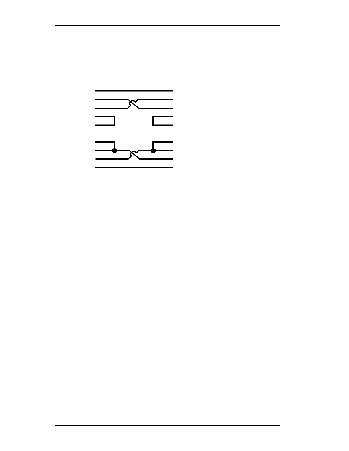
The size of the characters is the same on the 9425, 9445,
9465, and 9474 printers. However, there are more dots per
horizontal inch on the 9465. Because of this, parallel
characters on the 9465 only have a high er number of dots per
character (across the character width). The dots per character
is the same for the 9425, 9445 , and 9474 printers for al l
characters, and for the 9465 printer for serial charac ters. The
examples below show the difference between parallel
characters and serial characters.
Serial Characters
Parallel Characters
Font Characters
per Inch
Standard 12
Reduced 24
Bold 6
OCR-A 10
Font Characters
per Inch
Standard 10
Reduced 14
Bold 5
OCR-A 10
Quick References
6. Quick References
6-3
Page 70

Parallel Character Width (in Dots) for the 9425, 9445,
and 9474
The following table shows the width of the 9425, 9445, and
9474 characters in dots. Uppercase I is the narrowest
character (fewest dots per character). Uppercase M is the
widest character (most dots per character).
*Inter-character gap
Serial Character Width (in Dots) for 9465
*Inter-character gap
Value/Font Dots Wide ICG*
IM
1/Standard 7 14 2
2/Reduced 2 7 1
3/Bold 7243
5/OCR-A 16 16 3
6/UPC HR1 12 12 2
7/UPC HR2 10 10 1
Value/Font Dots Wide ICG*
IM
1/Standard 7 14 2
2/Reduced 2 7 1
3/Bold 7243
5/OCR-A 16 16 3
6/UPC HR1 12 12 2
7/UPC HR2 10 10 1
9400 Series Programmer’s Manual
6-4
Page 71

Parallel Character Width (in Dots) for 9465
*Inter-character gap
The table below shows the character width (in dots) for the
9420/9440 fonts. There is no inter-character gap for the
9420/9440 fonts.
Parallel Character Width (in Dots) for 9420/9440 Fonts
Value/Font Dots Wide ICG*
IM
1/Standard 10 20 3
2/Reduced 3 10 1
3/Bold 6284
5/OCR-A 19 19 4
6/UPC HR1 18 18 2
7/UPC HR2 14 14 1
Value/Font Dots Wide
1/Standard 16
2/Reduced 8
3/Bold 32
5/OCR-A 19
6/UPC HR1 14
7/UPC HR2 10
Quick References
6. Quick References
6-5
Page 72

Serial Character Width (in Dots) for 9420/9440 Fonts
Bar Codes
The table bel ow lists bar code selections and values.
Value/Font Dots Wide
1/Standard 24
2/Reduced 14
3/Bold 48
5/OCR-A 24
6/UPC HR1 24
7/UPC HR2 16
Value Dots Wide
1UPC-A
2UPC-E
3 Interleaved 2 of 5
4 Code 39
5 Codabar
6 EAN-8
7 EAN-13
8 Code 128
9MSI
10 UPC/EAN+2
11 UPC/EAN+5
9400 Series Programmer’s Manual
6-6
Page 73

Bar Code Densities
Because the 9465 printhead has more dots per horizontal
inch, parallel bar codes on the 9465 only have a higher density
than serial bar codes. (Bar co de densities ar e the same on
the 9425, 9445, and 9474 printers for all bar codes , and on the
9465 printer for serial bar codes.) The samples below show
the differ ence between parallel and serial bar codes.
Serial Bar Code
Parallel Bar Code
Quick References
6. Quick References
6-7
Page 74

Bar Code Densities (9425/9445/9474)
* For more information on Code 128, see Appendix B.
** This density is not supported on the 9474 printer.
Value Bar Code Density (Char /in)
1 Code 39
I 2 of 5
Code 128 *
MSI
UPC/EAN
6.63
12.02
8.74 (alphanumeric)
17.48 (numeric only)
6.87
80% standard density
2 Code 39
I 2 of 5
Code 128 *
MSI
UPC/EAN
3.32
6.87
5.83 (alphanumeric)
11.66 (num eri c only )
5.34
120% standard density
3 Code 39
I 2 of 5
Code 128 *
MSI
4.01
4.93
4.37 (alphanumeric)
8.74 (numeric only)
4.01
4 Code 39**
I 2 of 5
12.02
3.01
5 Code 39 6.01
9400 Series Programmer’s Manual
6-8
Page 75

Bar Code Densities (9420/9440)
* For more information on Code 128, see Appendix B.
Val ue Bar Code Density (Char/in)
1 Code 39
I 2 of 5
Code 128*
MSI
6.63
12.02
8.74 (a lp hanumeric)
17.48 (n um er i c onl y)
6.87
2 Code 39
I 2 of 5
Code 128*
MSI
3.32
6.87
5.83 (a lp hanumeric)
11.66 (n um eric only)
5.34
3 Code 39
I 2 of 5
Code 128*
MSI
4.01
4.93
4.37 (a lp hanumeric)
8.74 (n um eric only)
4.01
4 Code 39
I 2 of 5
12.02
3.01
5 Code 39 6.01
Quick References
6. Quick References
6-9
Page 76
Bar Code Densities (9465, Parallel Print)
* For more information on Code 128, see Appendix B.
Value Bar Code Density (Char/in)
1 Code 39
I 2 of 5
Code 128*
MSI
UPC/EAN
6.63
12.02
8.74 (alphanumeric)
17.48 (numeric only)
6.87
87% standa rd density
2 Code 39
I 2 of 5
Code 128*
MSI
UPC/EAN
3.32
6.87
5.83 (alphanumeric)
11.66 (numeric only)
5.34
117% standa rd density
3 Code 39
I 2 of 5
Code 128*
MSI
4.01
4.93
4.37 (alphanumeric)
8.74 (numeric only)
4.01
4 Code 39
I 2 of 5
12.02
3.01
5 Code 39 6.01
9400 Series Programmer’s Manual
6-10
Page 77

Bar Code Densities (9465, Serial Print)
* For more information on Code 128, see Appendix B.
Value Bar Code Density (Char /in)
1 Code 39
I 2 of 5
Code 128 *
MSI
UPC/EAN
6.63
12.02
8.74 (alphanumeric)
17.48 (numeric only)
6.87
80% standard density
2 Code 39
I 2 of 5
Code 128 *
MSI
UPC/EAN
3.32
6.87
5.83 (alphanumeric)
11.66 (num eri c only )
5.34
120% standard density
3 Code 39
I 2 of 5
Code 128 *
MSI
4.01
4.93
4.37 (alphanumeric)
8.74 (numeric only)
4.01
4 Code 39
I 2 of 5
12.02
3.01
5 Code 39 6.01
Quick References
6. Quick References
6-11
Page 78

Line Width
The following tables show the horizontal and vertical line
widths . On the 9425/9445/9474 and 9420/9440 printers, the
line widths are the same for horizontal and vertical lines. On
the 9465, horizontal and vertical lin e widths are different.
Line Widths (9425/9445/9474 and 9420/9440)
The following table shows the horizontal and vertical line
widths for the 9425/9445/9474 and 9420/9440 printers.
Li ne Width
Line
Num b er Appearanc e Inches MM
1 .005 .13
2 .010 .26
3 .015 .40
4 .021 .53
5 .026 .66
6 .031 .79
7 .036 .92
8 .042 1.06
9 .046 1.16
10 .052 1.32
1 1 .057 1.44
12 .062 1.57
13 .067 1.70
14 .072 1.82
15 .078 1.98
9400 Series Programmer’s Manual
6-12
Page 79

Horizontal Line Widths (9465)
The following table shows the horizontal line widths for the
9465.
Li ne Width
Line
Number Appearance Inches MM
1.005.13
2.010.26
3.015.40
4.021.53
5.026.66
6.031.79
7.036.92
8.0421.06
9.0461.16
10 .052 1.32
11 .057 1.44
12 .062 1.57
13 .067 1.70
14 .072 1.82
15 .078 1.98
Quick References
6. Quick References
6-13
Page 80

Vertical Line Widths (9465)
The following table shows the vertical line widths for the 9465.
Line Width
Line
Number Appearance Inches MM
1.003.076
2.008.177
3 .01 1 .279
4.015.381
5.019.457
6.023.558
7.027.660
8.030.762
9.034.863
10 .038 .939
1 1 .042 1.041
12 .046 1.143
13 .049 1.244
14 .053 1.346
15 .057 1.422
9400 Series Programmer’s Manual
6-14
Page 81

Special Characters
The following table shows the ASCII code for special
characters available in the standard font.
Code 128 Function Codes
The following table shows the ASCII code for the Code 128
func t i on code s.
ASCII Code Symbol Description
~128
~129
~130
~131
~132
~133
~134
~135
~136
Hashed box
Pound or Lira
Yen
Kronna
Deutsche mark
Markka
Schilling
Half sign
Rupee
ASCII Code Function Code
~134
~129
~128
~132
F
1
F
2
F
3
F
4
Quick References
6. Quick References
6-15
Page 82

9420/9440 Horizontal Print Location
If the printer is set for 9420/9440 compatible mode, the field
location starts at the nearest 8th dot (nearest 0.04 inch) to the
locati on you enter. The following table shows the offline and
online values you may use for the horizontal print location
when the printer is in 9420/9440 compatible mode. If you use
a value that is not listed, the print position shifts plus or minus
to the closest number in the table. The maximum shift is 0.02
inch (0.5mm).
NOTE: If the pri nter is not in 9420/9440 compatible
mode, the default horizontal field location is the
dot near est to the loca tion you enter (nearest
0.0052 inch).
Offline Online
inches mm tomms
0.06 001.6 0
0.10 002.7 10
0.14 003.7 21
0.19 004.8 31
0.23 005.8 42
0.27 006.9 52
0.31 008.0 63
0.35 009.0 74
0.39 010.1 84
0.44 01 1.1 95
0.48 012.2 105
0.52 013.2 116
0.56 014.3 126
0.60 015.4 137
0.64 016.4 148
0.69 017.5 158
0.73 018.5 169
0.77 019.6 179
0.81 020.7 190
Offline Online
inches mm tomms
0.85 021.7 201
0.89 022.8 211
0.94 023.8 222
0.98 024.9 232
1.02 025.9 243
1.06 027.0 253
1.10 028.1 264
1.14 029.1 275
1.19 030.2 285
1.23 031.2 296
1.27 032.3 306
1.31 033.3 317
1.35 034.4 328
1.39 035.5 338
1.44 036.5 349
1.48 037.6 359
1.52 038.6 370
1.56 039.7 380
1.60 040.8 391
9400 Series Programmer’s Manual
6-16
Page 83

Offline Online
inches mm tomms
1.64 041.8 402
1.69 042.9 412
1.73 043.9 423
1.77 045.0 433
1.77 045.0 433
1.81 046.0 444
1.85 047.1 455
1.89 048.2 465
1.94 049.2 476
1.98 050.3 486
2.02 051.3 497
2.06 052.4 507
2.10 053.5 518
2.14 054.5 529
2.19 055.6 539
2.23 056.6 550
2.27 057.7 560
2.31 058.7 571
2.35 059.8 582
2.39 060.9 592
2.44 061.9 603
2.48 063.0 613
2.52 064.0 624
2.56 065.1 634
2.60 066.2 645
2.64 067.2 656
2.69 068.3 666
2.73 069.3 677
2.77 070.4 687
2.81 071.4 698
2.85 072.5 708
Offline Online
inches mm tomms
2.89 073.6 719
2.94 074.6 730
2.98 075.7 740
3.02 076.7 751
3.06 077.8 761
3.10 078.9 772
3.14 079.9 783
3.19 081.0 793
3.23 082.0 804
3.27 083.1 814
3.31 084.1 825
3.35 085.2 835
3.39 086.3 846
3.44 087.3 857
3.48 088.4 867
3.52 089.4 878
3.56 090.5 888
3.60 091.6 899
3.64 092.6 910
3.69 093.7 920
3.73 094.7 931
3.77 095.8 941
3.81 096.8 952
3.85 097.9 962
3.89 099.0 973
3.94 100.0 984
3.98 101.1 994
Quick References
6. Quick References
6-17
Page 84

ASCII Characters
The follow i ng table shows the characters available in each
font. HR1 and HR2 are human readable fonts for bar codes.
Character Std Reduced OCRA Bold HR1 HR2
yes yes no no no no
# yesyes nononono
$ yes yes yes yes no no
% yesyes nononono
^ ¢ ¢ no ¢ no no
& yesyes nononono
* yes no no no no
( yes yes no yes no no
) yes yes no yes no no
[ [ yes nononono
] ] yes nononono
‘(grave) yes yes no no no no
{ yesyes nononono
} yesyes nononono
~yesyes
s
no no no
,(comma) yes yes
l
no no no
" yes yes yes no no no
- yes yes yes yes yes no
= yesyes nononono
_(underscore) yes yes
d
no no no
+ yes yes yes no no no
.yesyes
y
yes no no
/ yes yes yes yes no no
’(apostrophe) yes yes
h
no no no
: yes yes no yes no no
; yesyes nononono
yes yes yes no no no
yes yes yes no no no
? yesyes nononono
\yesyes
v
¥nono
| nono nononono
0-9 yes yes yes yes yes yes
A-Z yes yes yes yes no H N *
a-z yesyes nononono
yes = What you enter is what prints.
no = Charact e r does not exist in thi s font; nothi ng print s.
* Uppercase H and N are the only alphabetic characters that
print in the Human Readable fonts. All other characters
are numeric.
9400 Series Programmer’s Manual
6-18
Page 85

Printable Characters by Font
Follo w i ng are the printabl e characters (not at actual size).
Human Readable 1 and Human Readable 2 are not available
offline.
Standard
Reduced
Bold
OCR-A
Human Readable
(HR2)
Human Readable
(HR1)
Quick References
6. Quick References
6-19
Page 86

English/Metric Conversion
Inches TOMM Inches TOMM Inches TOMM Inches TOMM
- - 0.060 15 0.075 19 0.100 25
0.125 31 0.150 38 0.175 44 0.200 50
0.225 57 0.250 63 0.275 70 0.300 76
0.325 82 0.350 89 0.375 95 0.400 101
0.425 108 0.450 114 0.475 121 0.500 127
0.525 133 0.550 140 0.575 146 0.600 152
0.625 159 0.650 165 0.675 171 0.700 178
0.725 184 0.750 191 0.775 197 0.800 203
0.825 209 0.850 216 0.875 222 0.900 228
0.925 235 0.950 241 0.975 247 1.000 254
1.025 260 1.050 267 1.075 273 1.100 279
1.125 286 1.150 292 1.175 298 1.200 305
1.225 311 1.250 317 1.275 324 1.300 330
1.325 336 1.350 343 1.375 349 1.400 356
1.425 362 1.450 368 1.475 375 1.500 381
1.525 387 1.550 394 1.575 400 1.600 406
1.625 413 1.650 419 1.675 425 1.700 432
1.725 438 1.750 445 1.775 450 1.800 457
1.825 463 1.850 470 1.875 476 1.900 483
1.925 489 1.950 495 1.975 502 2.000 508
2.025 514 2.050 520 2.075 527 2.100 533
2.125 540 2.150 546 2.175 552 2.200 558
2.225 565 2.250 571 2.275 578 2.300 584
2.325 590 2.350 597 2.375 603 2.400 609
2.425 616 2.450 622 2.475 628 2.500 635
2.525 641 2.550 648 2.575 654 2.600 660
2.625 667 2.650 673 2.675 679 2.700 686
2.725 692 2.750 698 2.775 705 2.800 711
2.825 717 2.850 724 2.875 730 2.900 736
2.925 743 2.950 749 2.975 755 3.000 762
3.025 768 3.050 775 3.075 781 3.100 787
3.125 794 3.150 800 3.175 806 3.200 813
3.225 819 3.250 825 3.275 832 3.300 838
3.325 844 3.350 850 3.375 857 3.400 863
3.425 869 3.450 876 3.475 882 3.500 889
3.525 895 3.550 902 3.575 908 3.600 914
3.625 921 3.650 927 3.675 933 3.700 939
3.725 946 3.750 952 3.775 959 3.800 965
3.825 971 3.850 978 3.875 984 3.900 990
3.925 996 3.950 1003 3.975 1009 4.000 1016
4.025 1022 4.050 1028 4.075 1035 4.100 1041
4.125 1048 4.150 1054 4.175 1060 4.200 1067
4.225 1073 4.250 1079 4.275 1086 4.300 1092
4.325 1099 4.350 1105 4.375 1111 4.400 1118
9400 Series Programmer’s Manual
6-20
Page 87

English/Metric Conversion (cont.)
Inches TOMM Inches TOMM Inches TOMM Inches TOMM
4.425 1124 4.450 1130 4.475 1137 4.500 1143
4.525 1149 4.550 1156 4.575 1162 4.600 1168
4.625 1175 4.650 1181 4.675 1187 4.700 1194
4.725 1200 4.750 1206 4.775 1212 4.800 1219
4.825 1225 4.850 1232 4.875 1238 4.900 1245
4.925 1251 4.950 1257 4.975 1263 5.000 1270
5.025 1276 5.050 1283 5.075 1289 5.100 1295
5.125 1302 5.150 1308 5.175 1314 5.200 1321
5.225 1327 5.250 1333 5.275 1340 5.300 1346
5.325 1352 5.350 1359 5.375 1365 5.400 1371
5.425 1378 5.450 1384 5.475 1390 5.500 1397
5.525 1403 5.550 1409 5.575 1416 5.600 1422
5.625 1429 5.650 1435 5.675 1441 5.700 1448
5.725 1454 5.750 1460 5.775 1467 5.800 1473
5.825 1479 5.850 1486 5.875 1492 5.900 1499
5.925 1505 6.950 1511 5.975 1518 6.000 1524
6.025 1530 6.050 1537 6.075 1543 6.100 1549
6.125 1556 6.150 1562 6.175 1568 6.200 1575
6.225 1581 6.250 1588 6.275 1594 6.300 1600
6.325 1606 6.350 1613 6.375 1619 6.400 1626
6.425 1632 6.450 1638 6.475 1644 6.500 1651
TOMM = Tenths of millimeters
Quick References
6. Quick References
6-21
Page 88

9400 Series Programmer’s Manual
6-22
Page 89

Appendix A: Sample Data Streams
This appe ndi x contains sample data streams fo r formats,
batches, and graphics. The illustrations show the tags that are
printed from these data streams.
Formats, Text and Bar Code Fields
This exam pl e shows a standard format with three text and one
bar code field.
Sample Format Data Stream
{ F1,0550,0507;ONLINE p
T00,I,000,0475,0050,1,1,0,0,B p
T01,I,000,0406,0050,1,1,0,0,B p
T02,I,000,0017,0253,1,1,0,0,B p
B00,I,000,0124,0093,1,1,0,0177,1 p
}
Sample Batch Data Stream
{ B1,2,3,1,1,0,c;BATCH1 p
T00;TEST FORMAT 1 p
T01;S/N 97464B p
T02;$12.34 p
B00;0012345678905 p
}
Sample Tag
Appendix A:
Sample Data Streams
A-1
Page 90

Line Fields
This exam pl e shows how to use line fields to create a box.
Sample Format Data Stream
{ F2,0550,0507;BOX p
L0,50,50,0,304,10 p
L1,50,50,1,304,10 p
L2,50,304,0,304,10 p
L4,304,50,1,316,10 p
}
Sample Batch Data Stream
{ B2,1,0,1,1,1,C;BOXTEST p }
Sample Tag
9400 Series Programmer’s Manual
A-2
Page 91

Graphic Images
This Graphic data stream
precedes the format that uses it.
Sample Graphic Data
Stream
{ G3,0,0,0,0 p
;dHsHd p
;dHsHd p
;dHsHd p
;eGsGe p
;eHqHe p
;fGqGf p
;fHoHf p
;fHoHf p
;gGoGg p
;gHmHg p
;hGMGh p
;hGMGh p
;hGMGh p
;iFMFi p
;iFMFi p
;jEMEj p
;jEMEj p
;jEMEj p
;kHgHk p
;kHgHk p
;lGgGl p
;lHeHl p
;lHeHl p
;mGeGm p
;mGeGm p
;nGcGn p
;nGcGn p
;nGcGn p
;oFcFo p
;oGaGo p
;pFaFp p
;pFAFp p
;qEAEq p
;qEAEq p
;qEAEq p
;rDADr p
;rDADr p
;sCACs p
;sCACs p
;sCACs p
;tBABt p
;tBABt p
;uCu p
;uCu p
;uCu p
;vAv p
}
Appendix A:
Sample Data Streams
Appendix A: Sample Data Streams
A-3
Page 92

Sample Format Data Stream
{ F3,0550,0507;GRAPHIC p
T0,I,0,400,100,1,1,0,0,B p
G3,200,200 p
}
Sample Batch Data Stream
{ B3,1,1,1,1,0,1;LETTER-A p
T0;LETTER A GRAPHIC p
}
Sample Tag
9400 Series Programmer’s Manual
A-4
Page 93
Compressed Graphic Data
This exam pl e shows the same graphic data stream in
compress ed fo rm at.
Sample Compressed Graphic Data Stream
{ G3,0,0,0,0 p
;3dHsHd p
;eGsGe p
;eHqHe p
;fGqGf p
;2fHoHf p
;gGoGg p
;gHmHg p
;3hGMGh p
;2iFMFi p
;3jEMEj p
;2kHgHk p
;lGgGl p
;2lHeHl p
;2mGeGm p
;3nGcGn p
;oFcFo p
;oGaGo p
;pFaFp p
;pFAFp p
;3qEAEq p
;2rDADr p
;3sCACs p
;2tBABt p
;3uCu p
;vAv p
}
Appendix A:
Sample Data Streams
Appendix A: Sample Data Streams
A-5
Page 94

Sample Format Data Stream
{ F3,0550,0507;GRAPHIC p
T0,I,0,400,100,1,1,0,0,B p
G3,200,200 p
}
Sample Batch Data Stream
{ B3,1,1,1,1,0,1;LETTER-A p
T0;LETTER A GRAPHIC p
}
Sample Tag
9400 Series Programmer’s Manual
A-6
Page 95

Appendix B: Code 128 Information
The 128 bar code is divided into 3 character sets (Code A,
Code B, and Code C). Depending on the character set used,
the same bar pattern can be one of three characters. Table 1,
at the end of this appendix, lists the characters in each
character set.
Code A contains upper cas e letters (A-Z), special
characters, and control characters. Code A does
not have lower case letters.
Code B contai ns upper and lower c ase alphanumeric
characters and speci al characters . Code B does
not have control characters.
Code C character set contains pairs of num bers. In code
C, each bar pattern represents a pair of numbers,
ranging from 00 to 99.
When the data contains at least four numbers in a row, 128
switches to code C, then prints one bar pattern for each pair of
numbers. This doubles the numeric data per inch.
Therefore, it may be bet ter to pad numeri c data with a zero if i t
has an odd number of characters. The bar codes below show
the differ ence between an odd number of numeric characters
and an even number of numeric characters. Do this only if
your system can ignore leading zeros.
Bar Code 1
Data = 1234567
Bar Code 2
Data = 012345 67
Appendix B:
Code 128 Information
B-1
Page 96

Bar Code 2 is not as wi de as Bar Code 1 because all of its
characters are pri nted with bar symbols from code C .
Only 6 of Bar Code 1’s ch aracters are printed in code C. The
other character has to be printed in code B. Whenever 128
switches from one character set to another, it adds bar
patterns that tell a scanner to switch character sets. These
extra bar pat terns cause wider bar codes.
Bar Code Width
The width of a Code 128 bar code is determined this way:
• If there are four or more numbers in a row, an even
number of them print in code C.
• If there are four or more numbers in a row with an odd
quantity (e.g., 7 numbers in a row), one of them pr i nts in
code B.
• All other alphanumeric characters are printed in code B.
NOTE: The printer determines which character set to use
based on the data. No external control of character
set selection is required.
For a given quantity of data, the widest bar code will be the
one that switches character set most often. Suppose your
data has 14 ch aracters (8 numeri c + 6 alphabeti c).
The bar code for data arranged like this:
Bar code 1
Data = 1234ABC5678DEF
is wider than data arranged
like this:
Bar code 2
Data = 12345678ABCDEF
9400 Series Programmer’s Manual
B-2
Page 97

Here’s why bar code 1 is wider:
• The 8 numbers in each example appear in groups of
four or more, and they appear in ev en-numbered
quantities, theref ore, all 8 numbers will use code C.
• The 6 alphabetic characters will use code B.
Look at the example again. This time, data is underlined when
the character set changes.
The bar code for data arranged like this:
Bar code 1
Data = 1234
ABC5678DEF
is wider than data arranged
like this:
Bar code 2
Data = 12345678
ABCDEF
This shows that bar code width varies depending on how data
is arranged. Separating numeric and alphabetic characters
reduces the number of chara ct er set changes . Fewer
character set changes reduce bar code width.
Appendix B:
Code 128 Information
Appendix B: Code 128 Information
B-3
Page 98

The table below shows the characters per inch for Code 128.
The table shows the values for numeri c data, and fo r
alphanumeric data at each of the three densities available on
the printer. The characters per inch for your bar code will be
somewh ere between thes e tw o values, depending on the
mixture of numeric and alphabetic characters. For a precise
calculation of the width of your bar code, refer to the
specification for the Code 128 bar code.
NOTE: Bar codes printed in parallel mode (top of the bar
code toward top of tag) on the 9465 only have the
characters per inch shown in the following table.
Density Numeric
Data
Alphanumeric dat a
1 23.92 11.96
2 15.95 7.97
3 11.96 5.98
Density Numeric
Data
Alphanumeric dat a
1 17.48 8.74
2 11.66 5.83
3 8.74 4.37
9400 Series Programmer’s Manual
B-4
Page 99

Quiet Zone
When you estimate the area you’ll need for the bar code,
remember to add the length of the quiet zone. The quiet zone
is an area of white space requi red at the begi nning and end of
each bar code. The minimum size of the quiet zone is 0.10, or
10 times the width of the narrowest bar code element,
whichever is greater. The tables below show the minimum
size of the quiet zone at each density. For wand scanning, the
quiet zone should be 0.25 to 0.35 inch.
The minimum quiet zone for parallel bar codes printed on the
9465 are shown in the following table.
Density Quiet Zone
10.10 inch
20.15 inch
30.20 inch
Density Quiet Zone
1 0.10 inch
20.11 inch
3 0.15 inch
Appendix B:
Code 128 Information
Appendix B: Code 128 Information
B-5
Page 100

Function Codes
Code 128 has four function codes (f1-f4). These special
characters can be ent ered as:
• fixed character s w h en def i ning a co de 12 8 fiel d ( F or m a t
Entry)
• data when printing a batch (Data Entry).
Enter the special 128 function codes as follows :
to select this
Press these keys function code
F2 then 1 f1
F2 then 2 f2
F2 then 3 f3
F2 then 4 f4
The function code is displayed as F
1
, F2, F3, or F4.
9400 Series Programmer’s Manual
B-6
 Loading...