

Page 1
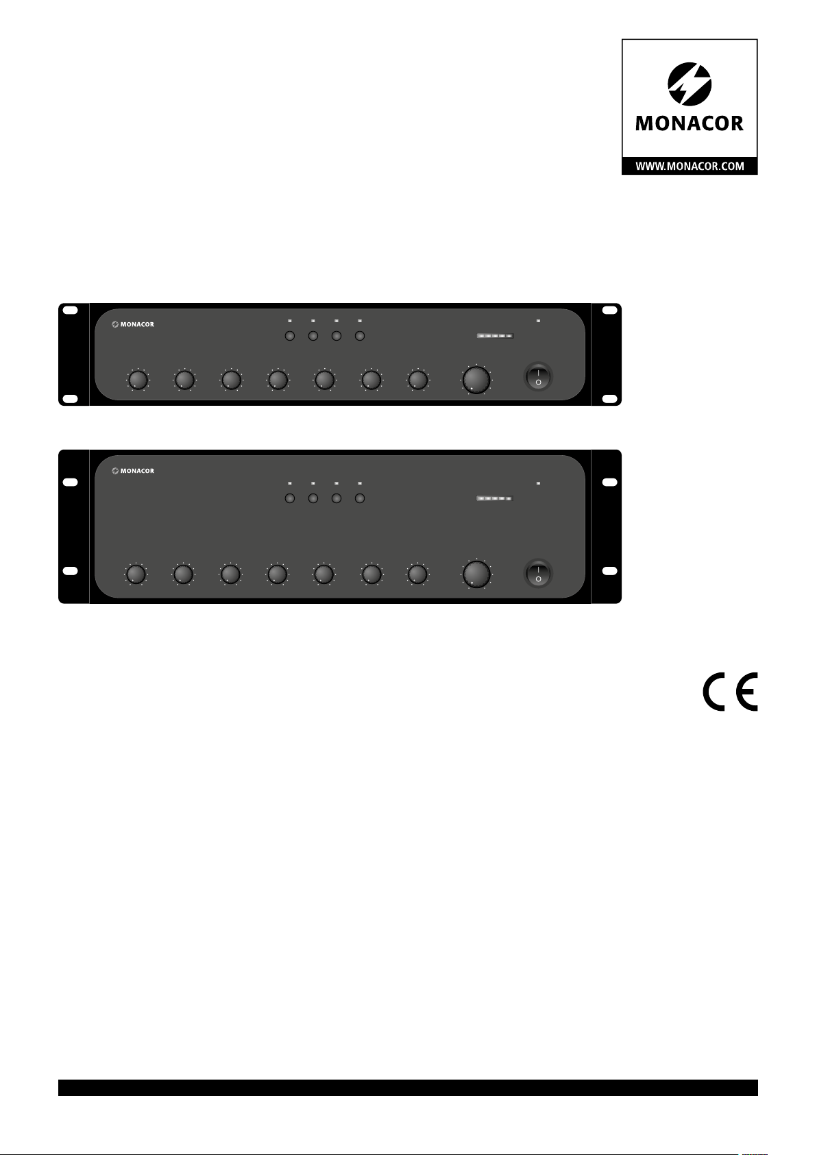
ELA-Mischverstärker
PA Mixing Amplifier
PA-924
CHANNEL 1 CHANNEL 2 CHANNEL 3 CHANNEL 4 AUX BASS TREBLE
PA-948
CHANNEL 1 CHANNEL 2 CHANNEL 3 CHANNEL 4 AUX BASS TREBLE
PA-924
Bestell-Nr. • Order No. 17.5060
LINE TUNER CD TAPE
LINE TUNER CD TAPE
PA-948
Bestell-Nr. • Order No. 17.5070
MASTER
MASTER
ON
4 6 8 10 CLIP
POWER
ON
4 6 8 10 CLIP
POWER
BEDIENUNGSANLEITUNG
INSTRUCTION MANUAL
MODE D’EMPLOI
ISTRUZIONI PER L’USO
GEBRUIKSAANWIJZING
MANUAL DE INSTRUCCIONES
INSTRUKCJA OBSŁUGI
SIKKERHEDSOPLYSNINGER
SÄKERHETSFÖRESKRIFTER
TURVALLISUUDESTA
ELECTRONICS FOR SPECIALISTS ELECTRONICS FOR SPECIALISTS ELECTRONICS FOR SPECIALISTS ELECTRONICS FOR SPECIALISTS
Page 2

Deutsch ...........Seite 4
English ............Page 7
Français ...........Page 10
Italiano............Pagina 13
Nederlands ........Pagina 16
Español ...........Página 19
Polski .............Strona 22
Dansk .............Sida 25
Svenska ...........Sidan 25
Suomi.............Sivulta 25
ELECTRONICS FOR SPECIALISTS ELECTRONICS FOR SPECIALISTS ELECTRONICS FOR SPECIALISTS ELECTRONICS FOR SPECIALISTS
2
Page 3
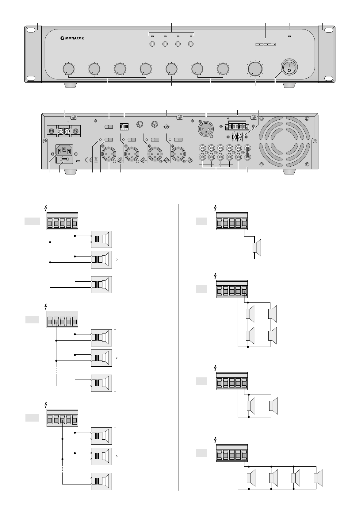
SPEAKER
SPEAKER
1 432 1
OUTPUT
100 V
PA-924
CHANNEL 1
CHANNEL 2 CHANNEL 3 CHANNEL 4 AUX BASS TREBLE
5
LINE TUNER CD TAPE
6
7
1010 11 12 13 14 15 16
SPEAKER
GAIN
MIX OUT
TAPE
L
R
OUTPUT
4 Ω
SPEAKER
OUTPUT
4 Ω
OUTPUT
CHIME
REMOTE
CD TUNER LINE
AUX
23
70V
100V
70V
100V
17 18
100V
DC INPUT
70V
MIC PRIORITY CHIME
19
CHIME
4T
2T
PH.PWR
OFF ON+48V
CH 1
GAIN
LINE MIC LINE MIC LINE MIC LINE MIC
2120
22 24 25
24V
230V
~
50Hz
FUSE
4Ω
50V
COM
INPUTS MIX OUT
1 2 3 4
DIP
ON
OFF
PH.PWR PH.PWR PH.PWR
OFF ON+48V
CH 2
GAIN
1
2- SIG +
3-SIG
VOLUME
- GN D
-
OFF ON+48V
CH 3
OFF ON+48V
CH 4
GAIN
➂
100 V
100 V
100 V
-
+
-
+
. . .
max. Belastung
max. load
PA-924: 240 W
PA-948: 480 W
RMS
RMS
-
+
4 6 8 10ONCLIP
MASTER
8 9
4Ω
70V
50V
COM
100V
PRE
OUTREC
AMP
IN
POWER
➀
➁
4Ω
50V
COM
➅
-
4 Ω
+
4Ω
50V
COM
➆
SPEAKER
OUTPUT
70 V
SPEAKER
OUTPUT
50 V
4Ω
70V
50V
100V
COM
➃
-
-
70 V
70 V
+
+
-
-
70 V
70 V
+
+
. . .
. . .
-
-
70 V
70 V
+
+
4Ω
70V
50V
100V
COM
max. Belastung
max. load
PA-924: 240 W
PA-948: 480 W
RMS
RMS
SPEAKER
OUTPUT
70V
100V
4 Ω
-
+
4 Ω
-
4 Ω
+
--
4 Ω
+
4Ω
50V
COM
4 Ω
+
➇
8 Ω
-
8 Ω
+
-
+
➄
-
50 V
50 V
50 V
+
-
+
. . .
max. Belastung
max. load
PA-924: 240 W
PA-948: 480 W
RMS
RMS
-
+
SPEAKER
OUTPUT
4 Ω
4Ω
70V
50V
100V
COM
➈
-
+
16 Ω
-
+
16 Ω
-
+
16 Ω
-
16 Ω
+
3
Page 4

ELA-Mischverstärker
Diese Anleitung richtet sich an den Installateur des Geräts mit Fachkenntnissen in der
Deutsch
100-V (bzw. 70-V/ 50-V)-Beschallungstechnik.
Für die Bedienung (☞ Kapitel 5) ist dagegen
kein technisches Fachwissen erforderlich.
Bitte lesen Sie die Anleitung vor dem
Betrieb gründlich durch und heben Sie sie für
ein späteres Nachlesen auf. Auf der ausklappbaren Seite 3 finden Sie alle beschriebenen
Bedienelemente und Anschlüsse.
1 Übersicht
Die Abbildungen 1 und 2 zeigen das Modell
PA-924. Die Bedienelemente und Anschlüsse
des Modells PA-948 sind identisch.
1.1 Frontseite
1 Montagewinkel (2 ×) für den Rackeinbau
2
Tasten LINE, TUNER, CD und TAPE, um
den entsprechenden Eingang (23) für den
AUX-Kanal auszuwählen;
zur Anzeige der Auswahl leuchtet die LED
über der jeweiligen Taste
3 Ausgangspegelanzeige
4 Betriebsanzeige ON
5
Mischregler zum Einstellen der Lautstärke
für die Kanäle 1 bis 4
6
Mischregler zum Einstellen der Lautstärke
für den AUX-Kanal
7 Klangregler für die Höhen (TREBLE) und
Tiefen (BASS)
8 Regler MASTER für die Gesamtlautstärke
9 Ein- /Ausschalter POWER
Hinweis: Liegt eine 24-V-Gleichspannung
von einer Notstromeinheit am Anschluss DC
INPUT (10) an, lässt sich der Verstärker nicht
ausschalten.
1.2 Rückseite
10
Schraubklemmen DC INPUT zum Anschluss einer Notstromversorgung (⎓ 24 V)
11
Umschalter CHIME für die Art des Gongs:
„2T“ = 2-Ton-Gong, „4T“ = 4-Ton-Gong
12
DIP-Schalter 1 bis 4 für die Kanäle 1 bis 4:
Um einem Kanal Vorrang gegenüber dem
AUX-Kanal zuzuweisen, den jeweiligen
Schalter auf „ON“ stellen.
13
Regler CHIME VOLUME zum Einstellen
der Gonglautstärke
14
Ausgang MIX OUT (XLR, sym.) für das
Mischsignal; der Ausgangspegel ist unabhängig vom Regler MASTER (8)
15 Schraubklemmen SPEAKER OUTPUT (ab-
ziehbar) für den Anschluss der Lautsprecher: ☞ Kapitel 4.2.1 und Abbildungen
auf Seite 3
16
Schraubklemmen CHIME REMOTE für den
Anschluss eines Tasters zur Gong-Auslösung
17
Netzbuchse zum Anschluss an eine Steckdose 230 V/ 50 Hz über das beiliegende
Netzkabel
18 Halter für die Netzsicherung
Eine durchgebrannte Sicherung nur durch
eine gleichen Typs ersetzen!
19 LED +48 V, jeweils für die Kanäle 1 bis 4:
leuchtet, wenn die Phantomspeisung für
den Kanal eingeschaltet ist
20
Schalter PH.PWR, jeweils für die Kanäle
1 bis 4, zum Einschalten („ON“) der
48-V-Phantomspeisung
Die Hinweise in Kapitel 4.2.2 beachten.
21
Eingang (XLR, sym.), jeweils für die Kanäle 1 bis CH 4, zum Anschluss eines Mikrofons oder einer Mono-Tonquelle mit
Line-Signalpegel
22
GAIN-Regler, jeweils für die Kanäle 1 bis4,
zur Anpassung der Eingangsempfindlichkeit an die angeschlossene Tonquelle
23
Eingänge LINE, TUNER, CD und TAPE
(Cinch) zum Anschluss von Stereo-Tonquellen mit Line-Signal pegel
24
Ausgang REC (Cinch) zum Anschluss
eines Stereo-Aufnahmegeräts; der Ausgangspegel ist unabhängig vom Regler
MASTER(8)
25 Ausgang PRE OUT und Eingang AMPIN
(Cinch) zum Einschleifen eines Geräts zur
Klangbearbeitung ☞ Kapitel 4.2.6
Hinweis: Werden PRE OUT und AMP IN nicht
zum Anschluss eines Geräts genutzt, müssen
sie, wie in der Abb. 2, über die Steckbrücke
miteinander verbunden sein. Anderenfalls ist
der Signalfluss unterbrochen.
2 Hinweise für den
sicherenGebrauch
Das Gerät entspricht allen relevanten Richtlinien der EU und trägt deshalb das -Zeichen.
WARNUNG
Das Gerät ist nur zur Verwendung im In-
•
nenbereich geeignet. Schützen Sie es vor
Tropf- und Spritzwasser und hoher Luft
feuchtigkeit. Der zulässige Einsatztemperaturbereich beträgt 0 – 40 °C.
Stellen Sie keine mit Flüssigkeit gefüllten
•
Gefäße, z. B. Trinkgläser, auf das Gerät.
Die in dem Gerät entstehende Wärme muss
•
durch Luftzirkulation abgegeben werden.
Decken Sie darum die Lüftungsöffnungen
des Gehäuses nicht ab.
Trennen Sie das Gerät sofort von der Strom-
•
versorgung, wenn:
1.
sichtbare Schäden am Gerät oder am
Netzkabel vorhanden sind,
2.
nach einem Sturz oder Ähnlichem der
Verdacht auf einen Defekt besteht,
3. Funktionsstörungen auftreten.
Geben Sie das Gerät in jedem Fall zur Re-
paratur in eine Fachwerkstatt.
Das Gerät wird mit lebensgefährlicher Netzspannung
versorgt. Nehmen Sie deshalb niemals selbst Eingriffe
am Gerät vor und stecken Sie
nichts in die Lüftungsöffnungen! Es besteht die Gefahr
eines elektrischen Schlags.
Ziehen Sie den Netzstecker nie am Kabel
•
aus der Steckdose, fassen Sie immer am
Stecker an.
Verwenden Sie zur Reinigung nur ein tro-
•
ckenes, weiches Tuch, keine Chemikalien
oder Wasser.
Wird das Gerät zweckentfremdet, nicht
•
richtig angeschlossen, falsch bedient oder
nicht fachgerecht repariert, kann keine Garantie für das Gerät und keine Haftung für
daraus resultierende Sach- oder Personenschäden übernommen werden.
Soll das Gerät endgültig aus dem
Betrieb genommen werden, übergeben Sie es zur umweltgerechten
Entsorgung einem örtlichen Recyclingbetrieb.
3 Einsatzmöglichkeiten
Dieser ELA-Mono-Verstärker mit fünf mischbaren Eingangskanälen ist speziell für den
Betrieb mit 100-V (bzw. 70-V/ 50-V)-Lautsprechern konzipiert. Es ist jedoch auch möglich,
stattdessen nieder ohmige Lautsprecher zu
verwenden.
Der Verstärker verfügt über:
− vier XLR-Eingänge für die Kanäle 1 bis 4 mit
einstellbarer Empfindlichkeit (Line-Pegel bis
Mikrofonpegel);
Phantomspeisung (+48 V) für jeden Kanal
einzeln schaltbar
− vier Cinch-Eingänge, von denen einer für
den Kanal AUX ausgewählt wird
− DIP-Schalter, um den Kanälen 1 bis 4 Vorrang gegenüber dem AUX-Kanal zuzuweisen
− einen XLR- und einen Cinch-Ausgang für
das Mischsignal
− Cinch-Buchsen zum Einschleifen eines Geräts zur Klangbearbeitung
− einen Anschluss für einen Taster zum Auslösen eines 2-Ton- oder 4-Ton-Gongs
− einen Anschluss für eine Notstromversorgung (⎓ 24 V)
− Schutzschaltungen gegen Überlast, Kurzschluss und Überhitzung
-
4
Page 5

4 Installation
Die Installation sollte nur durch eine qualifizierte Fachkraft vorgenommen werden!
4.1 Aufstellung
Der Verstärker lässt sich frei aufstellen oder
in ein Rack für Geräte mit einer Breite von
482 mm (19”) einbauen. In jedem Fall muss
Luft ungehindert durch alle Lüftungsöffnungen strömen können, damit eine ausreichende
Kühlung des Verstärkers gewährleistet ist.
4.1.1 Rackeinbau
Die zwei mitgelieferten Montagewinkel (1) an
die Geräteseiten anschrauben. Im Rack werden 2Höheneinheiten (für Modell PA-924)
bzw. 3Höheneinheiten (für Modell PA-948)
benötigt. Damit das Rack nicht kopflastig
wird, muss der Verstärker im unteren Bereich
des Racks eingeschoben werden. Für eine sichere Befestigung reichen die Montagewinkel
allein nicht aus. Zusätzlich müssen Seitenschienen oder eine Bodenplatte das Gerät halten.
Die vom Verstärker abgegebene erhitzte
Luft muss aus dem Rack austreten können.
Anderenfalls kommt es im Rack zu einem
Hitzestau, wodurch nicht nur der Verstärker,
sondern auch andere Geräte im Rack beschädigt werden können. Bei unzureichendem
Wärmeabfluss in das Rack eine Lüftereinheit
einsetzen.
4.2 Anschlüsse und Einstellungen
WARNUNG
4.2.1 Lautsprecher
Es lassen sich entweder 100-V-Lautsprecher
(bzw. 70-V- oder 50-V-Lautsprecher) oder
niederohmige Lautsprecher anschließen. Die
Lautsprechertypen dürfen nicht gemischt angeschlossen werden.
Je nach Lautsprechertyp die entsprechenden
Klemmen SPEAKER OUTPUT (15) verwenden:
− 100-V-Lautsprecher an „100V“ und „COM“
anschließen: ☞ Abb. 3
(70-V-Lautsprecher an „70V“ und „COM“,
50-V-Lautsprecher an „50V“ und „COM“:
Abb. 4 bzw. 5)
☞
Der Verstärker darf mit max. 240 W Sinus
(PA-924) bzw. max. 480 W Sinus (PA-948)
durch die Lautsprecher belastet werden.
− Niederohmige Lautsprecher an „4Ω“ und
„COM“ anschließen. Die LautsprecherGesamtimpedanz muss min. 4 Ω betragen.
Die Abb. 6 bis 9 zeigen verschiedene Arten,
die Mindestimpedanz von 4 Ω einzuhalten.
Es gibt aber noch weitere Möglichkeiten.
Beim Anschluss auf die richtige Polarität achten. Die Klemme COM ist der Minuspol.
Die Klemmleiste lässt sich zur besseren Handhabung von ihrer Steckverbindung abziehen.
Im Betrieb liegt an den Lautsprecherklemmen (15) berührungsgefährliche Spannung
bis 100 V an. Alle Anschlüsse
dürfen nur bei ausgeschalteter ELA-Anlage durchgeführt
werden!
4.2.2 Tonquellen für die Kanäle 1 – 4
Jeder Kanal 1 bis 4 verfügt über eine XLRBuchse (21) zum Anschluss eines Mikrofons oder einer Mono-Tonquelle mit LineSignalpegel (z. B. Mono-Ausgang eines
Mischpults). Die Buchse ist symmetrisch
beschaltet, kann aber über einen entsprechenden Adapter auch asymmetrisch angeschlossen werden, z. B. über das Audiokabel
MCA-158 (Cinch XLR) von MONACOR.
Mit dem GAIN-Regler (22) des Kanals die
Eingangsempfindlichkeit an den Ausgangspegel der Tonquelle anpassen: bei Anschluss
eines Mikrofons den Regler nach rechts
aufdrehen, bei Anschluss eines Geräts mit
Line-Pegel den Regler nach links zurückdrehen. Die Reglerposition muss ggf. nach der
Inbetriebnahme korrigiert werden: Wenn zur
Einstellung der gewünschten Lautstärke der
Mischregler (5) des Kanals sehr weit zurückgedreht (Ton zu laut bzw. verzerrt) oder sehr
weit aufgedreht (Ton zu leise) werden muss,
den GAIN-Regler entsprechend zurück- bzw.
aufdrehen.
Phantomspeisung
Um für einen Kanal die 48-V-Phantomspeisung einzuschalten (z. B. bei Anschluss eines
Kondensatormikrofons), den zugehörigen
Schalter PH.PWR (20) auf „ON“ stellen. Bei
eingeschalteter Phantomspeisung leuchtet die
LED +48 V (19).
ACHTUNG
1. Betätigen Sie den Schalter nur bei ausgeschaltetem Verstärker (Schaltgeräusche).
2. Schalten Sie die Phantomspeisung nur
ein, wenn eine phantomgespeiste Tonquelle angeschlossen ist. Tonquellen, die
nicht für Phantomspeisung ausgelegt
sind (z. B. Mikrofon mit asymmetrischem
Ausgang), können durch sie beschädigt
werden.
4.2.3 Tonquellen für den AUX-Kanal
Es sind vier Eingänge (23) für den Anschluss
von Stereo-Tonquellen mit Line-Signal pegel
vorhanden (z. B. Tuner, CD / MP3-Spieler, PC).
Mit der entsprechenden Taste (2) auf der Vorderseite wird im Betrieb einer der Eingänge
für den AUX-Kanal ausgewählt.
Die Geräte jeweils an ein Cinch-Buchsenpaar L / R anschließen. Im Verstärker werden die Signale der beiden Stereo-Kanäle zu
einem Mono-Signal gemischt.
4.2.4 Vorrangschaltung
Mit den DIP-Schaltern 1 bis 4 (12) lässt sich
jedem einzelnen Kanal 1 bis 4 Vorrang gegen
über dem AUX-Kanal zuweisen (Schalterstellung „ON“). Die Lautstärke des AUX-Kanals
wird stark abgesenkt, wenn auf einem vorrangigen Kanal ein Signal (z. B. eine Mikrofondurchsage) vorliegt.
-
4.2.5 Taster für Gong-Auslösung
Über einen angeschlossenen Taster ist das
Auslösen eines Gongs möglich. Den Taster
an die Klemmen CHIME REMOTE (16) anschließen.
Gong einstellen
Nach der Inbetriebnahme mit dem Schalter
CHIME (11) die Art des Gongs einstellen
(„2T“ = 2-Ton-Gong, „4T“ = 4-Ton-Gong)
und mit dem Regler CHIME VOLUME (13) die
Lautstärke für den Gong einstellen.
4.2.6 Gerät zur Klangbearbeitung
Über die Cinch-Buchsen PRE OUT und AMPIN
(25) ist es möglich, ein Gerät zur Klangbearbeitung (z. B. Equalizer, Effekt gerät) einzuschleifen: Das Mischsignal wird über PRE
OUT herausgeführt, durchläuft das Gerät zur
Klang bearbeitung und gelangt über AMPIN
zurück in den Verstärker.
1)
Die Steckbrücke, die die Buchsen PRE OUT
und AMP IN verbindet, entfernen.
2) Den Eingang des einzuschleifenden Geräts
an den Ausgang PRE OUT anschließen.
3) Den Ausgang des einzuschleifenden Geräts an den Eingang AMP IN anschließen.
Hinweis: Wird das eingeschleifte Gerät entfernt,
nicht vergessen, PRE OUT und AMP IN wieder über
die Steckbrüke zu verbinden. Anderenfalls ist der
Signalfluss unterbrochen.
4.2.7 Zusätzlicher Verstärker und
Aufnahmegerät
Der XLR-Ausgang MIX OUT (14) kann zum
Anschluss eines weiteren Verstärkers (oder
eines anderen nachfolgenden Audiogeräts)
genutzt werden. Den Ausgang mit einem
symmetrisch beschalteten Line-Pegel-Eingang
verbinden.
Für den Anschluss eines Tonaufnahmegeräts eignet sich der Ausgang REC (24). Für
den Anschluss eines Stereo-Geräts sind zwei
Buchsen L / R vorhanden. Da der Verstärker
monofon arbeitet, sind die Signale an beiden
Buchsen identisch.
Das Ausgangssignal von MIX OUT und REC ist
unbeeinflusst von der Einstellung des Reglers
MASTER (8).
4.2.8 Strom- und Notstromversorgung
1) Soll der Verstärker bei einem Netzausfall
weiterarbeiten, die Schraubklemmen DC
INPUT (10) mit einer Notstromversorgung
(⎓ 24 V) verbinden, z. B. mit der Notstromeinheit PA-24ESP von MONACOR.
Hinweise:
1. Liegen ⎓ 24 V an den Klemmen DC INPUT an,
ist der Verstärker auch in Betrieb, wenn der
Ein- /Ausschalter POWER (9) auf „Aus“ steht.
Besteht bei anliegender Notversorgungsspannung auch die Netzversorgung, bewirkt das
Betätigen des Ein- /Ausschalters ein Umschalten zwischen Notstrom- und Netzbetrieb.
2. Im Notstrombetrieb gibt der Verstärker eine
geringere Leistung als im Netzbetrieb ab.
2)
Zum Schluss das beiliegende Netzkabel
zuerst in die Netzbuchse (17) und dann
in eine Steckdose (230 V/ 50 Hz) stecken.
Deutsch
5
Page 6

5 Bedienung
Um Schaltgeräusche zu vermeiden, die angeschlossenen Tonquellen vor dem Verstärker
Deutsch
PA-924 /-948 einschalten. Ist am PA-924 /-948
ein nachfolgender Verstärker angeschlossen,
diesen zuletzt einschalten. Nach dem Betrieb
die Geräte in umgekehrter Reihenfolge wieder
ausschalten.
1)
Um eine zu hohe Lautstärke zu vermeiden,
vor dem ersten Einschalten den Gesamtlautstärkeregler MASTER (8) ganz nach
links zurückdrehen.
2) Den Verstärker mit dem Schalter POWER
(9) einschalten ( I = „Ein“, O = „Aus“).
Bei eingeschaltetem Gerät leuchtet die
Betriebsanzeige ON (4).
Hinweis: Wird der Verstärker bei Netzausfall
über eine Notstromeinheit betrieben, ist der
Ein- /Ausschalter ohne Funktion.
3)
Den MASTER-Regler so weit aufdrehen,
dass die nachfolgenden Einstellungen gut
über die Lautsprecher zu hören sind.
4)
Für den AUX-Kanal die Tonquelle auswählen: diejenige Taste (2) drücken, die dem
Eingang (23), an dem die Tonquelle angeschlossen ist, entspricht (z. B. Taste CD
für die Tonquelle am Eingang CD); die LED
über der Taste leuchtet.
5)
Mit den Mischreglern CHANNEL 1 bis
CHANNEL4 (5) und AUX (6) für jeden
Kanal die gewünschte Lautstärke einstellen. Die Regler von nicht benutzten Kanälen ganz nach links zurückdrehen.
Ist ein Taster zur Gong-Auslösung angeschlossen, diesen nach Bedarf betätigen
(z. B. vor einer Durchsage).
Hinweis: Die Lautstärke des AUX-Kanals wird
stark abgesenkt:
– für die Dauer des Gongs
– wenn auf einem vorrangigen Kanal ein Signal,
(z. B. eine Durchsage) vorhanden ist
6) Mit dem MASTER-Regler die gewünschte
Lautstärke für die ELA-Anlage einstellen.
Der Ausgangspegel wird durch die LEDKette (3) angezeigt. Leuchtet die rote LED
CLIP, den MASTER-Regler und /oder die
betreffenden Kanal-Mischregler entsprechend zurückdrehen.
VORSICHT
Das Ohr gewöhnt sich an hohe Lautstärken und empfindet sie nach einiger Zeit
als nicht mehr so hoch. Darum erhöhen
Sie eine hohe Lautstärke nach der Gewöhnung nicht weiter.
Stellen Sie die Lautstärke nie
sehr hoch ein. Hohe Lautstärken können auf Dauer
das Gehör schädigen!
6 Technische Daten
Sinusleistung
PA-924: � � � � � � � � � � � � 240 W
PA-948: � � � � � � � � � � � � 480 W
Musikleistung
PA-924: � � � � � � � � � � � � 340 W
PA-948: � � � � � � � � � � � � 680 W
Klirrfaktor:� � � � � � � � � � � � < 0,1 %
Lautsprecherausgang: � � � 100 V/ 70 V/ 50 V
4
Ω
Eingänge CH 1 – CH 4
Empfindlichkeit:� � � � � � � 2,5 – 100 mV
Anschluss:� � � � � � � � � � � XLR (symmetrisch)
Phantomspeisung: � � � � � ⎓ 48 V, für jeden Kanal
einzeln zuschaltbar
Eingänge AUX
Empfindlichkeit:� � � � � � � 350 mV
Anschluss:� � � � � � � � � � � Cinch Links / Rechts
Eingang AMP IN
Empfindlichkeit:� � � � � � � 1 V
Anschluss:� � � � � � � � � � � Cinch
Frequenzbereich:�� � � � � � � 50 – 16 000 Hz, ±3 dB
Klangregelung
Tiefen: � � � � � � � � � � � � � ±10 dB / 100 Hz
Höhen: � � � � � � � � � � � � � ±10 dB / 10 kHz
Störabstand: � � � � � � � � � � > 75 dB
Stromversorgung
Netzspannung: � � � � � � � 230 V/ 50 Hz
Leistungsaufnahme
PA-924: � � � � � � � � � � � 640 VA
PA-948: � � � � � � � � � � � 1090 VA
Notstromversorgung
PA-924: � � � � � � � � � � � � ⎓ 24 V/ 18 A
PA-948: � � � � � � � � � � � � ⎓ 24 V/ 27 A
Einsatztemperatur: � � � � � � 0 – 40 °C
Abmessungen (B × H × T)
PA-924: � � � � � � � � � � � � 482* × 95 × 390 mm
2 Höheneinheiten
PA-948: � � � � � � � � � � � � 482* × 137 × 395 mm
3 Höheneinheiten
Gewicht
PA-924: � � � � � � � � � � � � 13 kg
PA-948: � � � � � � � � � � � � 19 kg
* 430 mm ohne Montagewinkel
7)
Den Klang mit den Reglern TREBLE und
BASS (7) einstellen. Bei Bedarf anschließend die Lautstärkeeinstellung korrigieren.
Diese Bedienungsanleitung ist urheberrechtlich für MONACOR ® INTERNATIONAL GmbH & Co. KG geschützt. Eine Reproduktion für eigene kommerzielle Zwecke – auch auszugsweise – ist untersagt.
Änderungen vorbehalten.
6
Page 7

PA Mixing Amplifier
These instructions are intended for the installer of the unit with knowledge in 100 V
(or 70 V/ 50 V) PA technology. For operation
(☞chapter 5), however, no specific knowledge is required.
Please read the operating instructions
carefully prior to operating the unit andkeep
them for later reference. All control elements
and connections described can be found on
the fold-out page3.
1 Control Elements and
Connections
Figures 1 and 2 show the model PA-924.
The control elements and connections of the
model PA-948 are identical.
1.1 Front panel
1 Mounting bracket (2 ×) to install the unit
into a rack
2
Buttons LINE, TUNER, CD and TAPE to
select the corresponding input (23) for
the AUX channel;
to indicate the selection, the LED above
the respective button will light up
3 LEDs to indicate the output level
4 Power indicator ON
5 Mixing controls to adjust the volume for
the channels 1 to 4
6 Mixing control to adjust the volume for
the AUX channel
7 Tone controls BASS and TREBLE
8 Control MASTER to adjust the total vol-
ume
9 POWER switch
Note: It will not be possible to switch off the
amplifier when a 24 V DC voltage of an emergency power supply unit is available at the
terminals DC INPUT (10).
1.2 Rear panel
10 Screw terminals DC INPUT to connect an
emergency power supply unit (⎓ 24 V)
11 Selector switch CHIME to select the type
of chime:
“2T” = 2-tone chime,
“4T” = 4-tone chime
12
DIP switches 1 to 4 for the channels 1
to 4: To give a channel priority over the
AUX channel, set the respective switch
to “ON”.
13
Control CHIME VOLUME to adjust the
volume of the chime
14
Output MIX OUT (XLR, bal.) for the mixed
signal; the output level is independent of
the control MASTER (8)
15
Screw terminals SPEAKER OUTPUT (removable) to connect the speakers:
chapter 4.2.1 and figures on page 3
☞
16 Screw terminals CHIME REMOTE to con-
nect a pushbutton for chime triggering
17
Mains jack for connection to a socket
(230 V/ 50 Hz) by means of the mains cable
provided
18
Support for the mains fuse
Always replace a blown fuse by one of
the same type!
19
LEDs +48 V, one each for the channels
1 to 4; will light up when the phantom
power supply for the respective channel
is switched on
20
Switches PH.PWR, one each for the channels 1 to 4, to activate the 48 V phantom
power supply
Please observe the notes in chapter 4.2.2.
21 Inputs (XLR, bal.), one each for the chan-
nels 1 to 4, to connect a microphone or
a mono audio source with line signal level
22
Controls GAIN, one each for the channels
1 to 4, to match the input sensitivity to
the audio source connected
23 Inputs LINE, TUNER, CD and TAPE (RCA)
to connect stereo audio sources with line
signal level
24
Output REC (RCA) to connect a stereo
recorder; the output level is independent
of the control MASTER (8)
25
Output PRE OUT and input AMP IN
(RCA) to insert an audio processing unit
chapter 4.2.6
☞
Note: When PRE OUT and AMP IN are not
used for the insertion of a unit, they must be
connected by means of the jumper as shown
in figure 2; otherwise, the signal flow will be
interrupted.
2 Safety Notes
The unit corresponds to all relevant directives
of the EU and is therefore marked with .
WARNING
The unit is suitable for indoor use only. Pro
•
tect it against dripping water, splash water
and high air humidity. The admissible ambient temperature range is 0 – 40 °C.
Do not place any vessels filled with liquid,
•
e. g. drinking glasses, on the unit.
The heat generated inside the unit must be
•
dissipated by air circulation; never cover the
air vents of the housing.
Immediately disconnect the unit from the
•
power supply
1.
if the unit or the mains cable is visibly
damaged,
2.
if a defect might have occurred after the
unit was dropped or suffered a similar
accident,
3. if malfunctions occur.
In any case the unit must be repaired by
skilled personnel.
Never pull the mains cable to disconnect
•
the mains plug from the mains socket, always seize the plug.
For cleaning only use a dry, soft cloth; never
•
use water or chemicals.
The unit uses dangerous mains
voltage. Leave servicing to
skilled personnel and do not
insert anything into the air
vents; inexpert handling may
result in electric shock.
No guarantee claims for the unit and no li-
•
ability for any resulting personal damage or
material damage will be accepted if the unit
is used for other purposes than originally
intended, if it is not correctly connected
or operated, or if it is not repaired in an
expert way.
If the unit is to be put out of operation definitively, take it to a local
recycling plant for a disposal which
is not harmful to the environment.
3 Applications
This PA mono amplifier with five mixable input
channels is specially designed for operation
with 100 V (or 70 V/ 50 V) speakers. However, it is also possible to use low-impedance
speakers instead.
The amplifier provides:
− four XLR inputs for the channels 1 to 4
with adjustable sensitivity (line level to microphone level);
phantom power supply (+48 V) can be activated separately for each channel
− four RCA inputs, one of them to be selected
for the channel AUX
− DIP switches to give the channels 1 to 4
priority over the AUX channel
− an XLR output and an RCA output for the
mixed signal
− RCA jacks to insert an audio processing unit
− connection for a pushbutton to trigger a
2-tone chime or 4-tone chime
− connection for an emergency power supply
unit (⎓ 24 V)
− protective circuits against overload, short
circuit and overheating
-
English
7
Page 8

4 Installation
The amplifier should only be installed by
skilled personnel!
English
4.1 Setting up the amplifier
The amplifier can be set up on its own or
installed in a rack for units with a width of
482 mm (19”). In order to ensure sufficient
cooling of the amplifier, air must always be
able to flow freely through all air vents.
4.1.1 Installation into a rack
Screw the two mounting brackets (1) provided to the sides of the unit. In the rack,
2 rack spaces (for model PA-924) or 3 rack
spaces (for model PA-948) are required. To
prevent the rack from becoming top-heavy,
insert the amplifier into the lower section
of the rack. The mounting brackets are not
sufficient for fixing the amplifier safely; additionally use lateral rails or a bottom plate to
secure the amplifier.
The hot air given off by the amplifier must
be dissipated from the rack; otherwise, heat
will accumulate in the rack which may not
only damage the amplifier but also other units
in the rack. In case of insufficient heat dissipation, install a ventilation unit into the rack.
4.2 Connections and settings
WARNING
4.2.1 Connecting speakers
Either 100 V speakers (or 70 V or 50 V speakers) or low-impedance speakers can be connected. Never connect a combination of these
speaker types.
Use the appropriate terminals SPEAKER OUTPUT (15), depending on the speaker type:
− Connect 100 V speakers to “100V” and
“COM”: ☞ fig. 3
(70 V speakers to “70V” and “COM”;
50 V speakers to “50V” and “COM:
figs. 4 and 5, respectively)
☞
The admissible load by the speakers is
240 W RMS max. (PA-924) and
480 WRMS max. (PA-948) respectively.
− Connect low-impedance speakers to “4Ω”
and “COM”. The total impedance of the
speakers must not be less than 4 Ω.
Figures 6 to 9 show various options of how
to meet the minimum impedance of 4 Ω;
please note that other options are possible.
Always observe the correct polarity when
making the connections. The terminal COM
is the negative pole.
To make handling easier, the screw terminal
strip can be removed from its plug-in connection.
During operation, there is a
hazard of contact with a dangerous voltage of up to 100 V
at the speaker terminals (15).
Always switch off the PA system prior to making any connections!
4.2.2 Audio sources for the channels 1 – 4
Each of the channels 1 to 4 provides an XLR
jack (21) for the connection of a microphone
or mono audio source with line signal level
(e. g. mono output of a mixer). The jack is balanced; however, by means of an appropriate
adapter such as the audio cable MCA-158
(RCA XLR) from MONACOR, it can also be
used for an unbalanced connection.
Use the control GAIN (22) of the respective channel to match its input sensitivity to
the output level of the audio source: When
a microphone is connected, turn the control
clockwise; when an audio source with line
level is connected, turn the control anticlockwise. If required, readjust the control
GAIN after the amplifier has been set into
operation: When the mixing control (5) of the
channel must be turned back very far (sound
too loud or distorted) or turned up very far
(sound too low) to set the volume desired,
turn the control GAIN anti-clockwise or clockwise accordingly.
Phantom power supply
To activate the 48 V phantom power supply
for a channel (e. g. when a condenser microphone is connected), set the appropriate
switch PH.PWR (20) to “ON”. When the
phantom power supply has been activated,
the corresponding LED +48 V (19) will light
up.
ATTENTION
1. Only actuate the switch when the amplifier is switched off (switching noise).
2. Only activate the phantom power supply
when a phantom-powered audio source
is connected; audio sources not designed
for phantom power supply (e. g. microphone with unbalanced output) may be
damaged.
4.2.3 Audio sources for the AUX channel
The amplifier provides four inputs (23) for the
connection of stereo audio sources with line
signal level (e. g. tuner, CD / MP3 player, PC).
During operation, use the appropriate button
(2) on the front panel to select the desired
input for the AUX channel.
Connect each of the units to a pair of
RCA jacks L / R. In the amplifier, the signals
of the two stereo channels will be mixed to
a mono signal.
4.2.4 Priority function
The DIP switches 1 to 4 (12) can be used to
give the individual channels 1 to 4 priority
over the AUX channel (corresponding DIP
switches set to “ON”). The volume of the
AUX channel will be substantially attenuated as soon as a signal (e. g. a microphone
announcement) is available on a channel of
higher priority.
4.2.5 Pushbutton for chime triggering
A chime can be triggered by means of a connected pushbutton. Connect the pushbutton
to the terminals CHIME REMOTE (16).
Setting the chime
After switching on the amplifier, use the
switch CHIME (11) to select the type of chime
desired (“2T” = 2-tone chime, “4T” = 4-tone
chime) and then use the control CHIME VOLUME (13) to adjust the volume of the chime.
4.2.6 Audio processing unit
Use the RCA jacks PRE OUT and AMP IN
(25) to insert an audio processing unit (e. g.
equalizer, effect unit): The mixed signal will
be routed to the audio processing unit via
PRE OUT, processed and then returned to the
amplifier via AMP IN.
1) Remove the jumper connecting the jacks
PRE OUT and AMP IN.
2)
Connect the input of the unit to be inserted to the output PRE OUT.
3) Connect the output of the unit to be inserted to the input AMP IN.
Note: When removing the unit inserted, remember to connect PRE OUT and AMP IN by means
of the jumper; otherwise, the signal flow will be
interrupted.
4.2.7 Additional amplifier and recorder
The XLR output MIX OUT (14) can be used to
connect an additional amplifier (or a different
subsequent audio unit). Connect the output
to a balanced line level input.
The output REC (24) is suitable for the
connection of a recorder. For the connection
of a stereo unit, two jacks L / R are available.
The amplifier is monophonic; therefore, the
signals at the two jacks are identical.
The adjustment of the control MASTER (8)
will have no influence on the output signal
of MIX OUT and REC.
4.2.8 Power supply and
emergencypowersupply
1) To ensure continued operation of the am-
plifier after a mains failure, connect the
terminals DC INPUT (10) to an emergency
power supply unit (⎓ 24 V), e. g. the emergency power supply unit PA-24ESP from
MONACOR.
Notes:
1. When ⎓ 24 V is available at the terminals
DCINPUT, the amplifier will be in operation
even when the switch POWER (9) has been
set to “Off”. When both the emergency
power supply and the mains power supply
are available, the switch POWER will switch
between these two power supplies.
2. With emergency power supply, the amplifier will provide less power than with mains
power supply.
2) Finally, first connect the mains cable provided to the mains jack (17) and then to a
mains socket (230 V/ 50 Hz).
8
Page 9

5 Operation
To prevent switching noise, always switch on
the audio sources connected before switching on the amplifier PA-924 /-948. When a
subsequent amplifier is connected to the
PA-924 /-948, switch on the subsequent amplifier last. After operation, switch off the
units in reverse order.
1)
To prevent a volume which is too high, turn
the total volume control MASTER (8) to the
left stop before switching on the amplifier
for the first time.
2)
Use the switch POWER (9) to switch on
the amplifier ( I = “On”, O = “Off”). The
power indicator ON (4) will light up when
the amplifier is switched on.
Note: When, in case of a mains failure, the
amplifier is operated by means of an emergency
power supply unit, the switch POWER will have
no effect.
3) Turn up the control MASTER so that the
subsequent settings can be heard well via
the speakers.
4)
Select the audio source for the AUX channel: Press the button (2) that corresponds
to the input (23) to which the audio source
is connected (e. g. press the button CD for
the audio source connected to the input
CD); the LED above the respective button
will lightup.
5)
Use the mixing controls CHANNEL 1 to
CHANNEL4 (5) and AUX (6) to adjust the
volume desired for each channel. Turn
the controls of unused channels to the
left stop.
When a pushbutton for chime triggering is connected, actuate the pushbutton
as desired (e. g. prior to an announcement).
Note: The volume of the AUX channel will be
substantially attenuated:
– while the chime sounds
– when a signal (e. g. an announcement) is avail-
able on a channel of higher priority.
6) Use the control MASTER to adjust the volume desired for the PA system. The output level is indicated by the LED chain(3).
When the red LED CLIP lights up, turn
back the control MASTER and /or the mixing controls of the respective channels
accordingly.
CAUTION
Your ear will get accustomed to high
volumes which do not seem to be that
high after some time. Therefore, do not
further increase a high volume after getting used to it.
Never adjust the amplifier
to a very high volume. Permanent high volumes may
damage your hearing!
6 Specifications
RMS output power
PA-924: � � � � � � � � � � � � 240 W
PA-948: � � � � � � � � � � � � 480 W
Music power
PA-924: � � � � � � � � � � � � 340 W
PA-948: � � � � � � � � � � � � 680 W
THD: � � � � � � � � � � � � � � � � < 0�1 %
Speaker output: � � � � � � � � 100 V/ 70 V/ 50 V
4
Ω
Inputs CH1 – CH4
Sensitivity: � � � � � � � � � � 2�5 – 100 mV
Connection: � � � � � � � � � XLR (balanced)
Phantom power: � � � � � � ⎓ 48 V, can be addi-
tionally activated for
each channel
Inputs AUX
Sensitivity: � � � � � � � � � � 350 mV
Connection: � � � � � � � � � RCA left / right
Input AMP IN
Sensitivity: � � � � � � � � � � 1V
Connection: � � � � � � � � � RCA
Frequency range: � � � � � � � 50 – 16 000 Hz, ±3 dB
Tone control
Low frequencies: � � � � � � ±10 dB / 100 Hz
High frequencies: � � � � � ±10 dB / 10 kHz
S / N ratio: � � � � � � � � � � � � > 75 dB
Power supply
Mains voltage: � � � � � � � 230 V/ 50 Hz
Power consumption
PA-924: � � � � � � � � � � � 640 VA
PA-948: � � � � � � � � � � � 1090 VA
Emergency power supply
PA-924: � � � � � � � � � � � � ⎓ 24 V/ 18 A
PA-948: � � � � � � � � � � � � ⎓ 24 V/ 27 A
Ambient temperature: � � � 0 – 40 °C
Dimensions (W × H × D)
PA-924: � � � � � � � � � � � � 482* × 95 × 390 mm
2 rack spaces
PA-948: � � � � � � � � � � � � 482* × 137 × 395 mm
3 rack spaces
Weight
PA-924: � � � � � � � � � � � � 13 kg
PA-948: � � � � � � � � � � � � 19 kg
*430 mm without mounting brackets
English
7) Use the controls BASS and TREBLE (7) to
adjust the sound. Then readjust the volume, if required.
All rights reserved by MONACOR ® INTERNATIONAL GmbH & Co. KG. No part of this instruction manual
may be reproduced in any form or by any means for any commercial use.
Subject to technical modification.
9
Page 10
Amplificateur mixeur
PublicAdress
Cette notice s’adresse à l’installateur de
Français
l’appareil ayant des connaissances en sonorisation ligne 100 V (ou 70 V/ 50 V). Pour l’utilisation (☞ chapitre 5), en revanche, aucune
compétence technique n’est nécessaire.
Veuillez lire la notice avant le fonctionnement et conservez-la pour pouvoir, si besoin,
vous y reporter ultérieurement. Vous trouverez sur la page 3, dépliable, les éléments et
branchements.
1 Eléments et branchements
Les schémas 1 et 2 présentent le modèle
PA-924. Les éléments et branchements du
modèle PA-948 sont identiques.
1.1 Face avant
1 Etrier de montage (x 2) pour une instal-
lation en rack
2
Touches LINE, TUNER, CD et TAPE pour
sélectionner l’entrée correspondante (23)
pour le canal AUX ;
la LED au-dessus de la touche correspondante brille pour indiquer la sélection
3 VU-mètre à LEDs
4 Témoin de fonctionnement ON
5
Réglages de mixage pour régler le volume
pour les canaux 1 à 4
6 Réglage de mixage pour régler le volume
pour le canal AUX
7 Egaliseurs pour les aigus (TREBLE) et les
graves (BASS)
8 Réglage MASTER pour le volume général
9 Interrupteur Marche /Arrêt
Conseil : si une tension continue 24 V d’une
alimentation de secours est présente à la borne
DC INPUT (10), l’amplificateur ne peut pas être
éteint.
1.2 Face arrière
10
Bornes à vis DC INPUT pour brancher une
alimentation de secours (⎓ 24 V)
11 Sélecteur CHIME pour le type de gong :
«2T» = gong 2 sons, «4T» = gong 4 sons
12
Interrupteurs DIP 1 à 4 pour les canaux
1à 4 ; pour donner à un canal la priorité
sur le canal AUX, mettez l’interrupteur
correspondant sur «ON».
13
Réglage CHIME VOLUME pour régler le
volume du gong
14 Sortie MIX OUT (XLR, sym.) pour le signal
de mixage ; le niveau de sortie est indépendant du réglage MASTER (8)
15
Bornes à vis SPEAKER OUTPUT (amovible)
pour brancher les enceintes : ☞ chapitre
4.2.1 et schémas sur la page 3
16 Bornes à vis CHIME REMOTE pour bran-
cher un poussoir pour déclencher le gong
17
Prise secteur pour brancher à une prise
230 V/ 50 Hz via le cordon secteur livré
18 Porte fusible
Tout fusible fondu doit impérativement
être remplacé par un fusible de même
type !
19
LED +48V, respectivement pour les canaux
1 à 4 : brille lorsque l’alimentation fantôme pour le canal est activée
20
Sélecteur PH.PWR, respectivement pour
les canaux 1 à 4, pour activer («ON») l’alimentation fantôme 48 V
Respectez les conseils figurant dans le
chapitre 4.2.2.
21 Entrée (XLR, sym.), respectivement pour
les canaux 1 à 4, pour brancher un microphone ou une source audio mono avec
niveau de signal ligne
22
Réglage GAIN, respectivement pour les
canaux 1 à 4, pour adapter la sensibilité
d’entrée à la source audio reliée
23 Entrées LINE, TUNER, CD et TAPE (RCA)
pour brancher des sources audio stéréo
avec niveau de signal ligne
24
Sortie REC (RCA) pour brancher un enregistreur stéréo ; le niveau de sortie est
indépendant du réglage MASTER (8)
25 Sortie PRE OUT et entrée AMP IN (RCA)
pour insérer un appareil pour le traitement de signal ☞ chapitre 4.2.6.
Conseil : si PRE OUT et AMP IN ne sont pas
utilisées pour brancher un appareil, il faut,
comme sur le schéma 2, les relier entre elles
via le cavalier. Sinon le signal est interrompu.
2 Conseils de sécurité
etd’utilisation
L’appareil répond à toutes les directives nécessaires de l’Union Européenne et porte donc
le symbole .
AVERTISSEMENT L’appareil est alimenté par
une tension dangereuse.
Ne touchez jamais l’intérieur de l’appareil et ne
faites rien tomber dans
les ouïes de ventilation !
Risque de décharge électrique.
L’appareil n’est conçu que pour une utilisa-
•
tion en intérieur. Protégez-le des éclaboussures, de tout type de projections d’eau et
d’une humidité d’air élevée. La température
ambiante admissible est de 0 – 40 °C.
En aucun cas, vous ne devez pas poser
•
d’objet contenant du liquide ou un verre
sur l’appareil.
La chaleur dégagée par l’appareil doit être
•
évacuée par une circulation correcte de l’air.
En aucun cas, les ouïes de ventilation ne
doivent être obturées.
Débranchez l’appareil immédiatement de
•
l’alimentation dans les cas suivants :
1.
l’appareil ou le cordon secteur présentent des dommages visibles.
2.
après une chute ou accident similaire,
vous avez un doute sur l’état de l’appareil.
3. des dysfonctionnements apparaissent.
Dans tous les cas, les dommages doivent
être réparés par un technicien spécialisé.
Ne débranchez jamais l’appareil en tirant
•
sur le cordon secteur ; retirez toujours le
cordon secteur en tirant la fiche.
Pour le nettoyage, utilisez un chiffon sec et
•
doux, en aucun cas de produits chimiques
ou d’eau.
Nous déclinons toute responsabilité en
•
cas de dommages corporels ou matériels
résultants si l’appareil est utilisé dans un
but autre que celui pour lequel il a été
conçu, s’il n’est pas correctement branché
ou utilisé ou s’il n’est pas réparé par une
personne habilitée ; en outre, la garantie
deviendrait caduque.
Lorsque l’appareil est définitivement
retiré du service, vous devez le déposer dans une usine de recyclage
de proximité pour contribuer à son
élimination non polluante.
CARTONS ET EMBALLAGE
PAPIER À TRIER
3 Possibilités d’utilisation
Cet amplificateur mono Public Adress avec
5 canaux d’entrée mixables est spécialement
conçu pour un fonctionnement avec des enceintes 100 V (ou 70 V/ 50 V). Il est également
possible d’utiliser des enceintes basse impédance à la place.
L’amplificateur dispose de :
− 4 entrées XLR pour les canaux 1 à 4 avec
sensibilité réglable (niveau ligne à niveau
micro) ;
alimentation fantôme (+48 V) commutable
séparément pour chaque canal
− 4 entrées RCA, dont une est sélectionnée
pour le canal AUX
− interrupteurs DIP pour attribuer aux canaux
1 à 4 une priorité sur le canal AUX
− sortie XLR et sortie RCA pour le signal de
mixage
− prises RCA pour insérer un appareil pour le
traitement de signal
− branchement pour un poussoir pour déclencher un gong 2 sons ou 4 sons
− branchement pour alimentation de secours
(⎓ 24 V)
− circuits de protection contre les surcharges,
courts-circuits, surchauffes
10
Page 11

4 Installation
Seul un technicien qualifié peut effectuer
l’installation !
4.1 Positionnement
L’appareil peut être posé directement sur une
table ou installé dans un rack avec une largeur de 482 mm (19”). Dans tous les cas, l’air
doit pouvoir circuler librement via les ouïes de
ventilation pour assurer un refroidissement
suffisant de l’amplificateur.
4.1.1 Montage en rack
Vissez les deux étriers de montage livrés (1)
sur les côtés du boîtier. Dans le rack, 2 unités
(pour modèle PA-924) ou 3 unités (modèle
PA-948) sont nécessaires. Afin que le rack
ne se renverse pas, vous devez placer l’amplificateur dans la partie inférieure du rack.
Pour une fixation solide, les étriers de montage seuls ne sont pas suffisants, l’amplificateur doit en plus être maintenu par des rails
latéraux ou une plaque inférieure.
La chaleur dégagée par l’amplificateur
doit pouvoir être évacuée du rack. Sinon il
y a accumulation de chaleur dans le rack ce
qui pourrait endommager non seulement
l’amplificateur mais aussi les autres appareils
présents dans le rack. En cas de dégagement
insuffisant de chaleur, placez une unité de
ventilateur dans le rack.
4.2 Branchements et réglages
AVERTISSEMENT
4.2.1 Enceintes
Il est possible de brancher soit des enceintes
100 V (ou 70 V ou 50 V) soit des enceintes
basse impédance. Les types d’enceintes ne
doivent pas être mélangés.
Selon le type d’enceintes, utilisez les bornes
SPEAKER OUTPUT (15) correspondantes :
− Reliez des enceintes 100 V à «100 V» et
«COM» : ☞ schéma 3
(enceintes 70 V à «70 V» et «COM»,
enceintes 50 V à «50 V» et «COM» :
schémas 4 et 5)
☞
L’amplificateur ne doit pas dépasser une
charge maximale de 240 W RMS (PA-924)
ou 480 W RMS (PA-948) par les enceintes.
− Reliez des enceintes basse impédance à
«4 Ω» et «COM». L’impédance totale des
enceintes doit être de 4 Ω au moins.
Les schémas 6 à 9 présentent différentes
méthodes pour conserver une impédance
minimale de 4 Ω. Il existe cependant
d’autres possibilités.
Lors du branchement, veillez à respecter la
polarité ; la borne COM est le pôle moins.
La barrette de branchement peut être retirée
pour effectuer les branchements.
Pendant le fonctionnement,
une tension dangereuse
jusqu‘à 100 V est présente
aux bornes haut-parleurs
(15). Tous les branchements
ne doivent être effectués
que lorsque l‘installation
Public Adress est éteinte !
4.2.2 Sources audio pour lescanaux1 – 4
Chaque canal 1 à 4 dispose d’une prise XLR
(21) pour brancher un microphone ou une
source audio mono avec niveau de signal
ligne (par exemple sortie mono d’une table
de mixage). La prise est branchée en symétrique; elle peut, via un adaptateur adéquat,
être branchée en asymétrique, par exemple
via le cordon audio MCA-158 (RCA XLR)
de MONACOR.
Avec le réglage GAIN (22) du canal, adaptez la sensibilité d’entrée au niveau de sortie
de la source audio ; si vous branchez un microphone, tournez le réglage vers la droite, si
vous branchez un appareil avec niveau ligne,
tournez le réglage vers la gauche. La position
du réglage doit être corrigée, si besoin, après
la mise en fonction : si pour le réglage du
volume souhaité, le réglage de mixage (5) du
canal doit être tourné trop bas (le son est trop
fort ou distordu) ou trop haut (le son est trop
faible), tournez le réglage GAIN (22) vers la
gauche ou la droite en conséquence.
Alimentation fantôme
Pour activer l’alimentation fantôme 48 V pour
un canal (par exemple pour brancher un microphone à condensateur), mettez l’interrupteur correspondante PH.PWR (20) sur «ON».
Lorsque l’alimentation fantôme est activée,
la LED +48 V (19) brille.
ATTENTION
1. N’activez l’interrupteur que lorsque
l’amplificateur est éteint (bruits de commutation).
2. N’allumez l’alimentation fantôme que
si une source audio avec alimentation
fantôme est reliée. Des sources audio
non configurées pour une alimentation
fantôme (par exemple microphone avec
sortie asymétrique) pourraient être endommagées.
4.2.3 Sources audio pour le canal AUX
Quatre entrées (23) pour brancher des sources
audio stéréo avec niveau de signal ligne (par
exemple tuner, lecteur CD / MP3, PC) sont
prévues. Avec la touche correspondante (2)
sur la face avant, sélectionnez, pendant le
fonctionnement, une des entrées pour le
canal AUX.
Reliez chacun des appareils à une paire de
prises L / R (gauche / droite). Sur l’amplificateur,
les signaux des deux canaux stéréo sont mixés
en un signal mono.
4.2.4 Réglage du
circuitdecommutationprioritaire
Avec les interrupteurs DIP 1 à 4 (12), vous
pouvez donner à chaque canal 1 à 4 la priorité
sur le canal AUX (position interrupteur «ON»).
Le volume du canal AUX est fortement diminué si un signal (par exemple annonce micro)
est présent sur un canal prioritaire.
4.2.5 Poussoir pour
déclenchementdugong
Via un poussoir relié, il est possible de déclencher un gong. Reliez le poussoir aux bornes
CHIME REMOTE (16).
Réglage du gong
Après l’allumage, réglez le type de gong
(«2T» = gong 2 sons, «4T» = gong 4 sons)
avec le sélecteur CHIME (11) et avec le réglage
CHIME VOLUME (13), réglez le volume pour
le gong.
4.2.6 Appareil pour traitement de signal
Via les prises RCA PRE OUT et AMP IN (25),
il est possible d’insérer un appareil pour le
traitement du signal (par exemple égaliseur,
appareil à effets) : le signal de mixage est
sorti via PRE OUT, il passe par l’appareil pour
le traitement de signal et revient via AMP IN
dans l’amplificateur.
1)
Retirez le cavalier qui relie les prises PRE
OUT et AMP IN.
2) Reliez l’entrée de l’appareil à insérer à la
sortie PRE OUT.
3)
Reliez la sortie de l’appareil à insérer à
l’entrée AMP IN.
Remarque : lorsque l’appareil inséré est retiré,
n’oubliez pas de relier à nouveau PRE OUT et AMP
IN avec le cavalier. Sinon le signal est interrompu.
4.2.7 Amplificateur supplémentaire
etenregistreur
La sortie XLR MIX OUT (14) peut être utilisée
pour brancher un autre amplificateur (ou un
autre appareil audio suivant). Reliez la sortie
à une entrée niveau ligne symétrique.
Pour brancher un enregistreur audio,
la sortie REC (24) est adaptée. Pour brancher un appareil stéréo, les deux prises L / R
(gauche / droite) sont prévues. Puisque l’amplificateur fonctionne en mono, les signaux
aux deux prises sont identiques.
Le signal de sortie de MIX OUT et REC n’est
pas influencé par le réglage MASTER (8).
4.2.8 Alimentation et
alimentationdesecours
1)
Si l’amplificateur doit continuer à fonctionner en cas de coupure de courant,
reliez les bornes à vis DC INPUT (10) à
une alimentation de secours (⎓ 24 V), par
exemple à l’unité d’alimentation PA-24ESP
de MONACOR.
Conseils :
1. Si une tension de ⎓ 24 V est présente aux
bornes DC INPUT, l’amplificateur fonctionne
également lorsque l’interrupteur Marche /
Arrêt (9) est sur «Off». Si une alimentation secteur et une alimentation de secours
sont présentes, l’activation de l’interrupteur
Marche /Arrêt commute entre fonctionnement secteur et fonctionnement alimentation de secours.
2. En fonctionnement alimentation de secours,
l’amplificateur délivre une puissance plus
faible qu’en fonctionnement alimentation
secteur.
2)
Pour terminer, reliez le cordon secteur livré
à la prise secteur (17) et à une prise 230 V/
50 Hz.
Français
11
Page 12

5 Utilisation
Pour éviter tout bruit de commutation, allumez les sources audio reliées avant l’am-
Français
plificateur PA-924 / 948. Si un amplificateur
suivant est branché sur le PA-924 / 948, allumez cet amplificateur en dernier. Après le
fonctionnement, éteignez les appareils dans
l’ordre inverse.
1)
Pour éviter un volume trop élevé, avant
la première mise sous tension, tournez le
réglage général de volume MASTER (8)
entièrement à gauche.
2)
Allumez l’amplificateur avec l’interrupteur Marche /Arrêt (9) ( I = «marche»,
O= «arrêt»). Lorsque l’amplificateur est
allumé, la LED témoin de fonctionnement
ON (4) brille.
Remarque : si l’amplificateur fonctionne via
une alimentation de secours en cas de coupure
de courant, l’interrupteur Marche /Arrêt est sans
fonction.
3)
Tournez le réglage MASTER jusqu’à ce que
les réglages suivants sont bien audibles via
les enceintes.
4) Pour le canal AUX, sélectionnez la source
audio : appuyez sur la touche (2) qui correspond à l’entrée (23) à laquelle la source
audio est reliée (par exemple touche CD
pour la source audio à l’entrée CD) ; la LED
au-dessus de la touche brille.
5) Avec les réglages de mixage CHANNEL 1
à CHANNEL4 (5) et AUX (6), réglez le
volume souhaité pour chaque canal. Tournez les réglages des canaux non utilisés
entièrement à gauche.
Si un poussoir est branché pour
déclencher le gong, activez-le si besoin
(par exemple avant une annonce).
Remarque : le volume du canal AUX est fortement diminué :
– pendant la durée du gong
– si un signal (par exemple une annonce) est
présent sur un canal prioritaire.
6)
Avec le réglage MASTER, réglez le volume souhaité pour l’installation PA. Le
niveau de sortie est indiqué par la chaîne
de LEDs(3). Si la LED rouge CLIP brille,
tournez le réglage MASTER et / ou les réglages de mixage de canal concernés vers
la gauche en conséquence.
ATTENTION
L’oreille humaine s’habitue à des volumes
élevés et ne les perçoit plus comme tels
au bout d’un certain temps. Nous vous
conseillons donc de régler le volume et
de ne plus le modifier.
Ne réglez pas jamais le volume trop fort. Un volume
trop élevé peut, à long
terme, générer des troubles
de l’audition !
6 Caractéristiques techniques
Puissance RMS
PA-924 : � � � � � � � � � � � � 240 W
PA-948 : � � � � � � � � � � � � 480 W
Puissance musique
PA-924 : � � � � � � � � � � � � 340 W
PA-948 : � � � � � � � � � � � � 680 W
Taux de distorsion : � � � � � < 0,1 %
Sortie haut-parleurs : � � � � 100 V/ 70 V/ 50 V
4
Ω
Entrées CH 1 – CH 4
Sensibilité : � � � � � � � � � � 2,5 – 100 mV
Branchement : � � � � � � � � XLR (symétrique)
Alimentation fantôme : � ⎓ 48 V, commutable
séparément pour
chaque canal
Entrées AUX
Sensibilité : � � � � � � � � � � 350 mV
Branchement : � � � � � � � � RCA L / R (gauche / droit)
Entrée AMP IN
Sensibilité : � � � � � � � � � � 1 V
Branchement : � � � � � � � � RCA
Bande passante : � � � � � � � 50 – 16 000 Hz, ±3 dB
Egaliseur
Graves : � � � � � � � � � � � � ±10 dB / 100 Hz
Aigus : � � � � � � � � � � � � � ±10 dB / 10 kHz
Rapport signal / bruit : � � � � > 75 dB
Alimentation
Alimentation secteur : � � 230 V/ 50 Hz
Consommation
PA-924 : � � � � � � � � � � � 640 VA
PA-948 : � � � � � � � � � � � 1090 VA
Alimentation de secours
PA-924 : � � � � � � � � � � � � ⎓ 24 V/ 18 A
PA-948 : � � � � � � � � � � � � ⎓ 24 V/ 27 A
Température fonc� : � � � � � 0 – 40 °C
Dimensions (L × H × P)
PA-924 : � � � � � � � � � � � � 482* × 95 × 390 mm
2 unités
PA-948 : � � � � � � � � � � � � 482* × 137 × 395 mm
3 unités
Poids
PA-924 : � � � � � � � � � � � � 13 kg
PA-948 : � � � � � � � � � � � � 19 kg
* 430 mm sans étriers de montage
7)
Réglez la tonalité avec les réglages TREBLE
et BASS (7). Si besoin, corrigez ensuite le
réglage de volume.
Notice d’utilisation protégée par le copyright de MONACOR ® INTERNATIONAL GmbH & Co. KG. Toute
reproduction même partielle à des fins commerciales est interdite.
Tout droit de modification réservé.
12
Page 13
Mixer amplificatore PA
Queste istruzioni sono rivolte all‘installatore
dell‘apparecchio con conoscenze nella tecnica
di sonorizzazione a 100 V (e 70 V/ 50 V). Per
l’uso invece (☞ Capitolo 5), non è richiesta
nessuna conoscenza specifica.
Vi preghiamo di leggerle attentamente
prima dell‘installazione e di conservarle per un
uso futuro. A pagina 3, se aperta completamente, vedrete tutti gli elementi di comando
e i collegamenti descritti.
1 Panoramica
Le illustrazioni 1 e 2 rappresentano il modello
PA-924. Gli elementi di comando e i collegamenti del modello PA-948 sono identici.
1.1 Lato frontale
1
Angolo di montaggio (2 ×) per il montaggio in un rack
2
Tasti LINE, TUNER, CD e TAPE per scegliere
il relativo ingresso (23) per il canale AUX;
per visualizzare la scelta si accende il LED
sopra il relativo tasto
3 Indicazione del livello d‘uscita
4 Spia di funzionamento ON
5 Regolatori di miscelazione per impostare
il volume per i canali 1 a 4
6
Regolatore di miscelazione per impostare
il volume per il canale AUX
7
Regolatori toni per gli alti (TREBLE) e bassi
(BASS)
8
Regolatore MASTER per il volume globale
9 Interruttore on / off POWER
N. B.: Se al contatto DC INPUT (10) è presente
la tensione continua di 24 V di un gruppo di
continuità, l‘amplificatore non si spegne.
1.2 Lato posteriore
10
Morsetti a vite DC INPUT per il collegamento di un gruppo di continuità (⎓ 24 V)
11
Selettore CHIME per il modo del gong:
“2T“ = gong a 2 toni,
“4T“ = gong a 4 toni
12 DIP-switch 1 a 4 per i canali 1 a 4:
Per assegnare a un canale la priorità rispetto al canale AUX, mettere il relativo
switch su “ON”.
13
Regolatore CHIME VOLUME per impostare il volume del gong
14 Uscita MIX OUT (XLR, bil.) per il segnale
miscelato; il livello d‘uscita è indipendente
dal regolatore MASTER (8)
15
Morsetti a vite SPEAKER OUTPUT (stac
cabili) per il collegamento degli altoparlanti: ☞Capitolo 4.2.1 e illustrazioni a
pagina3
16 Morsetti a vite CHIME REMOTE per il col-
legamento di un pulsante per attivare il
gong
17 Presa per il collegamento con una presa
di rete 230 V/ 50 Hz tramite il cavo rete in
dotazione
18 Portafusibile
Sostituire un fusibile difettoso sempre con
uno dello stesso tipo!
19
LED +48 V, uno per ognuno dei canali
1a4: è acceso se l‘alimentazione phantom è stata attivata per il canale
20
Commutatore PH.PWR, per ognuno dei
canali 1 a 4, per attivare (“ON“) l‘alimentazione phantom 48 V
Rispettare le note nel capitolo 4.2.2.
21
Ingresso (XLR, bil.), per ognuno dei canali
1 a 4, per il collegamento di un microfono
o di una fonte audio mono con livello Line
22
Regolatore GAIN per ognuno dei canali
1a 4, per adattare la sensibilità d‘ingresso
alla fonte audio collegata
23
Ingressi LINE, TUNER, CD e TAPE (RCA)
per il collegamento di fonti audio stereo
con livello Line
24 Uscita REC (RCA) per il collegamento di
un registratore stereo; il livello d‘uscita è
indipendente dal regolatore MASTER (8)
25 Uscita PRE OUT e ingresso AMP IN (RCA)
per inserire un dispositivo per l‘elaborazione del suono ☞ Capitolo 4.2.6
N. B.: Se PRE OUT e AMP IN non vengono
usati per il collegamento di un dispositivo, devono essere collegati con il ponticello come si
vede in fig.2. Altrimenti, il flusso dei segnali è
interrotto.
2 Avvertenze per l‘uso sicuro
Quest’apparecchio è conforme a tutte le
direttive rilevanti dell’UE e pertanto porta la
sigla .
AVVERTIMENTO L’apparecchio è alimentato
con pericolosa tensione di
rete. Non intervenire mai
personalmente al suo interno e non inserire niente
nelle fessure di aerazione!
Esiste il pericolo di una scarica elettrica.
L’apparecchio è previsto solo per l’uso
•
all’interno di locali. Proteggerlo dall‘acqua
gocciolante, dagli spruzzi d‘acqua e da alta
umidità dell‘aria. La temperatura d’esercizio
ammessa è 0 – 40 °C.
Non depositare sull‘apparecchio dei con-
•
tenitori riempiti di liquidi, p. es. bicchieri.
Dev’essere garantita la libera circolazione
•
dell’aria per dissipare il calore che viene
prodotto all’interno dell‘apparecchio. Non
coprire in nessun modo le fessure d’aerazione.
Staccare l‘apparecchio subito dall‘alimen-
•
tazione se:
1. l’apparecchio o il cavo rete presentano
dei danni visibili;
2.
dopo una caduta o dopo eventi simili
sussiste il sospetto di un difetto;
3.
l’apparecchio non funziona corretta-
mente.
Per la riparazione rivolgersi sempre ad
un’officina competente.
Staccare il cavo rete afferrando la spina,
•
senza tirare il cavo.
Per la pulizia usare solo un panno morbido,
•
asciutto; non impiegare in nessun caso
acqua o prodotti chimici.
Nel caso d’uso improprio, di collegamenti
•
sbagliati, d’impiego scorretto o di riparazione non a regola d’arte dell‘apparecchio,
non si assume nessuna responsabilità per
eventuali danni consequenziali a persone
o a cose e non si assume nessuna garanzia
per l‘apparecchio.
Se si desidera eliminare l‘apparecchio definitivamente, consegnarlo
per lo smaltimento ad un‘istituzione
locale per il riciclaggio.
3 Possibilità d‘impiego
Questo amplificatore mono PA con cinque
canali d‘ingresso miscelabili è stato realizzato specialmente per il funzionamento con
altoparlanti 100 V (e 70 V/ 50 V). Tuttavia è
possibile usare anche altoparlanti a bassa
impedenza.
L‘amplificatore dispone di:
− quattro ingressi XLR per i canali 1 a 4 con
sensibilità regolabile (livello Line fino a livello microfono);
alimentazione phantom (+48 V) attivabile
per ogni canale singolarmente
− quattro ingressi RCA, dei quali uno viene
scelto per il canale AUX
− DIP-switch, per assegnare ai canali 1 a 4 la
priorità rispetto al canale AUX
− un‘uscita XLR e una RCA per il segnale
miscelato
− prese RCA per inserire un dispositivo per
l‘elaborazione del suono
− un contatto per un pulsante per attivare un
gong a 2 o a 4 toni
− un contatto per un gruppo di continuità
(⎓ 24 V)
− circuiti di protezione contro sovraccarico,
cortocircuito e surriscaldamento
Italiano
13
Page 14

4 Installazione
L‘installazione dovrebbe essere eseguita solo
da un perito qualificato!
Italiano
4.1 Collocamento
L‘amplificatore può essere collocato liberamente oppure può essere montato in un
rack per apparecchi della larghezza di 482 mm
(19”). In ogni caso deve essere possibile che
l‘aria esca liberamente attraverso tutte le
aperture di aerazione per garantire un raffreddamento sufficiente dell’amplificatore.
4.1.1 Montaggio in un rack
Avvitare ai lati dell‘apparecchio i due angoli
di montaggio (1) in dotazione. Nel rack sono
richieste 2 unità d’altezza (per il modello
PA-924) e 3 unità d‘altezza (per il modello
PA-948). Per evitare che il rack risulti squilibrato con troppi pesi in alto, è necessario
che l‘amplificatore venga montato nella parte
bassa del rack. Per un fissaggio sicuro non
sono sufficiente gli angoli di montaggio.
L‘apparecchio deve essere tenuto in più da
guide laterali oppure deve essere appoggiato
su un piano.
L‘aria riscaldata dall‘amplificatore deve
poter uscire dal rack. Altrimenti si può provocare un accumulo di calore nel rack con
possibili danni non solo all‘amplificatore ma
anche ad altri apparecchi presenti nel rack.
Se la dissipazione del calore è insufficiente
occorre montare un ventilatore nel rack.
4.2 Collegamenti e impostazioni
AVVERTIMENTO Durante il funzionamento,
ai morsetti per gli altoparlanti (15) è presente una
tensione pericolosa fino a
100 V. Tutti i collegamenti
devono essere eseguiti solo
con l‘impianto PA spento!
4.2.1 Altoparlanti
Si possono collegare altoparlanti 100 V
(e 70 V o 50 V) oppure altoparlanti a bassa
impedenza. I tipi di altoparlanti non devono
essere collegati in modo misto.
A seconda del tipo di altoparlante usare i
relativi morsetti SPEAKER OUTPUT (15):
− collegare altoparlanti 100 V con “100V“ e
“COM“: ☞ Fig. 3
(altoparlanti 70 V con “70V“ e “COM“,
altoparlanti 50 V con “50V“ e “COM“:
Figg. 4 e 5)
☞
L‘amplificatore sopporta un carico da parte
degli altoparlanti di 240 W RMS max.
(PA-924) e 480 W RMS max. (PA-948);
− collegare altoparlanti a bassa impedenza
con “4Ω“ e “COM“. L‘impedenza globale
degli altoparlanti deve essere 4 Ω min.
Le figg. 6 a 9 illustrano vari modi per rispettare l‘impedenza minima di 4 Ω. Esistono
comunque anche altre possibilità.
Durante il collegamento rispettare la corretta
polarità. Il morsetto COM è il polo negativo.
La morsettiera può essere staccata dalla sua
base per facilitare le operazioni.
4.2.2 Fonti audio per i canali 1 – 4
Ognuno dei canali 1 a 4 dispone di una presa
XLR (21) per il collegamento di un microfono
o di una fonte audio mono con livello Line
(p. es. l‘uscita mono di un mixer). Il settaggio
della presa è bilanciato, ma tramite un adattatore può essere collegata anche in modo
sbilanciato, p. es. per mezzo del cavo audio
MCA-158 (RCA XLR) di MONACOR.
Con il regolatore GAIN (22) del canale
adattare la sensibilità d‘ingresso al livello
d‘uscita della fonte: se si collega un microfono, girare il regolatore a destra, collegando
un apparecchio con livello Line girare il regolatore a sinistra. Dopo la messa in funzione
è eventualmente opportuno correggere la
posizione del regolatore: Se per impostare
il volume desiderato si deve chiudere moltissimo il regolatore (5) (audio troppo forte o
distorto) oppure se lo si deve aprire moltissimo
(suono troppo piano), chiudere o aprire in
corrispondenza il regolatore GAIN.
Alimentazione phantom
Per attivare l‘alimentazione phantom 48 V per
un canale (p. es. collegando un microfono a
condensatore) portare il relativo commutatore
PH.PWR (20) su “ON“. Con l‘alimentazione
phantom attivata, è acceso il LED +48 V (19).
ATTENZIONE
1. Azionare il commutatore solo con l‘amplificatore spento (rumori di commutazione).
2. Attivare l‘alimentazione phantom solo se
è collegata una fonte audio con alimentazione phantom. Le fonti audio non previste per l‘alimentazione phantom (p. es. un
microfono con uscita sbilanciata) possono
essere danneggiate da questa.
4.2.3 Fonti audio per il canale AUX
Esistono quattro ingressi (23) per il collegamento di fonti stereo con livello Line (p. es.
TUNER, lettori CD / MP3, PC). Durante il funzionamento, con il relativo tasto (2) sul lato
frontale si sceglie uno degli ingressi per il
canale AUX.
Collegare ognuno degli apparecchi con
una coppia di prese RCA L / R. Nell‘amplificatore, i segnali dei due canali stereo saranno
miscelati per diventare un segnale mono.
4.2.4 Circuito prioritario
Con i dip-switch 1 a 4 (12) si può assegnare a
ogni singolo canale 1 a 4 una priorità rispetto
al canale AUX (posizione “ON” dello switch).
Il volume del canale AUX viene fortemente
abbassato se su un canale prioritario è presente un segnale (p. es. un avviso fatto con
un microfono).
4.2.5 Pulsante per attivare il gong
Tramite un pulsante collegato è possibile
attivare un gong. Collegare il pulsante con i
morsetti CHIME REMOTE (16).
Impostare il gong
Dopo la messa in funzione, con il selettore
CHIME (11) impostare il modo del gong
(“2T“ = gong a 2 toni, “4T“ = gong a 4 toni)
e con il regolatore CHIME VOLUME (13)
impostare il volume per il gong.
4.2.6 Dispositivo per elaborare il suono
Tramite le prese RCA PRE OUT e AMP IN (25)
è possibile inserire un dispositivo per l‘elaborazione del suono (p. es. equalizer, unità
per effetti): Il segnale miscelato esce da PRE
OUT, attraversa il dispositivo per l‘elaborazione del suono e ritorna nell‘amplificatore
tramite AMP IN.
1) Togliere il ponticello che collega le prese
PRE OUT e AMP IN.
2)
Collegare l‘ingresso del dispositivo da
inserire con l‘uscita PRE OUT.
3)
Collegare l‘uscita del dispositivo da inserire
con l‘ingresso AMP IN.
N. B.: Se si toglie il dispositivo inserito non
dimenticare di collegare nuovamente PRE OUT e
AMP IN per mezzo del ponticello. Altrimenti, il
flusso dei segnali è interrotto.
4.2.7 Amplificatore supplementare
eregistratore
L‘uscita XLR MIX OUT (14) può essere usata
per collegare un ulteriore amplificatore (o un
altro apparecchio audio a valle). Collegare
l‘uscita con un ingresso bilanciato con livello
Line.
Per il collegamento di un registratore è
adatto l‘uscita REC (24). Per il collegamento
di un apparecchio stereo sono presenti due
prese L / R. Dato che l‘amplificatore funziona
in modo mono, i segnali delle due prese sono
identiche.
Il segnale d‘uscita di MIX OUT e REC non è
influenzato dall‘impostazione del regolatore
MASTER (8).
4.2.8 Alimentazione e
alimentazioned‘emergenza
1) Se l‘amplificatore deve continuare a fun-
zionare in caso di caduta di rete, colle
gare i morsetti a vite DC INPUT (10) con
un gruppo di continuità (⎓ 24 V), p. es.
con l’unità d‘emergenza PA-24ESP di
MONACOR.
N. B.:
1. Se ai morsetti DC INPUT sono presenti ⎓ 24 V,
l‘amplificatore è in funzione anche se l‘interruttore on /off POWER (9) è messo su “OFF”.
Se insieme all‘alimentazione d‘emergenza
è presente anche l‘alimentazione tramite la
rete, l‘azionamento dell‘interruttore on /off fa
cambiare fra funzionamento d‘emergenza e
funzionamento con la rete.
2. Funzionando con la corrente d‘emergenza,
l‘amplificatore eroga una potenza minore
rispetto al funzionamento con la rete.
2) Alla fine inserire il cavo rete in dotazione
dapprima nella presa (17) e quindi in una
presa di rete (230 V/ 50 Hz).
-
14
Page 15

5 Funzionamento
Per evitare i rumori di commutazione, accendere le fonti audio collegate prima dell‘amplificatore PA-924 /-948. Se al PA-924 /-948 è
collegato un amplificatore a valle, accedere
questo per ultimo. Dopo l‘uso, spegnere gli
apparecchi in ordine inverso.
1)
Per escludere un volume troppo forte,
prima della prima accensione girare tutto
a sinistra il regolatore del volume globale
MASTER (8).
2)
Accendere l‘amplificatore con l‘interruttore
POWER (9) ( I = “On“, O = “Off“). Con
l‘apparecchio acceso è accesa la spia di
funzionamento ON (4).
N. B.: Se in caso di caduta di rete, l‘amplificatore
funziona con un gruppo di continuità, l‘interruttore on /off è senza funzione.
3) Aprire il regolatore MASTER al punto da
poter ascoltare bene le impostazioni successive per mezzo degli altoparlanti.
4) Scegliere la fonte audio per il canale AUX:
premere il tasto (2) che corrisponde all‘ingresso (23) dove è collegata la fonte (p. es.
tasto CD per la fonte all‘ingresso CD);
il LED sopra il tasto si accende.
5)
Con i regolatori di miscelazione CHANNEL 1 a CHANNEL 4 (5) e AUX (6) impostare il volume per ogni canale. Girare
tutto a sinistra i regolatori dei canali non
usati.
Se è collegato un pulsante per attivare
il gong, azionarlo secondo necessità (p. es.
prima di un avviso).
N. B.: Il volume del canale AUX viene fortemente
abbassato:
– per la durata del gong
– se su un canale prioritario è presente un segnale
(p. es. un avviso)
6)
Con il regolatore MASTER impostare il
volume per l‘impianto PA. Il livello d‘uscita
viene visualizzato dalla catena di LED (3).
Se si accende il LED rosso CLIP, ridurre in
corrispondenza il regolatore MASTER e /o
i relativi regolatori di miscelazione dei canali.
ATTENZIONE
L’orecchio si abitua agli alti volumi e dopo
un certo tempo non se ne rende più
conto. Perciò non aumentare il volume
successivamente.
Mai tenere molto alto il
volume. A lungo andare,
il volume eccessivo può
procurare danni all’udito!
6 Dati tecnici
Potenza RMS
PA-924: � � � � � � � � � � � � 240 W
PA-948: � � � � � � � � � � � � 480 W
Potenza musicale
PA-924: � � � � � � � � � � � � 340 W
PA-948: � � � � � � � � � � � � 680 W
Fattore di distorsione: � � � < 0,1 %
Uscita altoparlanti: � � � � � 100 V/ 70 V/ 50 V
4
Ω
Ingressi CH 1 – CH 4
Sensibilità: � � � � � � � � � � 2,5 – 100 mV
Contatto: � � � � � � � � � � � XLR (bilanciato)
Alimentazione phantom: ⎓ 48 V, attivabile per
ogni canale separatamente
Ingressi AUX
Sensibilità: � � � � � � � � � � 350 mV
Contatto: � � � � � � � � � � � RCA L /R
Ingresso AMP IN
Sensibilità: � � � � � � � � � � 1 V
Contatto: � � � � � � � � � � � RCA
Gamma di frequenze: � � � � 50 – 16 000 Hz, ±3 dB
Regolazione toni
Bassi: � � � � � � � � � � � � � � ±10 dB / 100 Hz
Alti: � � � � � � � � � � � � � � � ±10 dB / 10 kHz
Rapporto S / R: � � � � � � � � � > 75 dB
Alimentazione
Tensione di rete: � � � � � � 230 V/ 50 Hz
Potenza assorbita:
PA-924: � � � � � � � � � � � 640 VA
PA-948: � � � � � � � � � � � 1090 VA
Alimentazione d‘emergenza
PA-924: � � � � � � � � � � � � ⎓ 24 V/ 18 A
PA-948: � � � � � � � � � � � � ⎓ 24 V/ 27 A
Temperatura d‘esercizio:� � 0 – 40 °C
Dimensioni (L × H × P)
PA-924: � � � � � � � � � � � � 482* × 95 × 390 mm
2 unità d‘altezza
PA-948: � � � � � � � � � � � � 482* × 137 × 395 mm
3 unità d‘altezza
Peso:
PA-924: � � � � � � � � � � � � 13 kg
PA-948 � � � � � � � � � � � � � 19 kg
* 430 mm senza angoli di montaggio
Italiano
7) Impostare i toni con i regolatori TREBLE e
BASS (7). Se necessario, correggere dopo
l‘impostazione del volume.
La MONACOR ® INTERNATIONAL GmbH & Co. KG si riserva ogni diritto di elaborazione in qualsiasi forma
delle presenti istruzioni per l’uso. La riproduzione – anche parziale – per propri scopi commerciali è vietata.
Con riserva di modifiche tecniche.
15
Page 16
ELA-mengversterker
Deze handleiding is bedoeld voor de installateur van het apparaat die de nodige vakkennis heeft met betrekking tot de 100 V-
(of 70 / 50 V-)geluidstechniek. Voor de bedie-
Nederlands
ning (☞ hoofdstuk 5) daarentegen is er geen
technische vakkennis vereist.
Lees de handleiding grondig door, alvorens het apparaat in gebruik te nemen, en
bewaar ze voor latere raadpleging. Op de
uitklapbare pagina 3 vindt u een overzicht
van alle bedieningselementen en de aansluitingen.
1 Overzicht
De afbeeldingen 1 en 2 tonen het model
PA-924. De bedieningselementen en aansluitingen van het model PA-948 zijn identiek.
1.1 Frontpaneel
1 Montageprofiel (2 ×) voor inbouw in een
rack
2
Toetsen LINE, TUNER, CD en TAPE, om
de respectieve ingang (23) voor het AUXkanaal te selecteren;
als aanduiding van de selectie, brandt de
led boven de betreffende toets
3 Aanduiding uitgangsniveau
4 POWER-led ON
5
Mengregelaars om het geluidsvolume
voor de kanalen 1 tot 4 in te stellen
6 Mengregelaar voor het instellen van het
volume voor het AUX-kanaal
7
Klankregelaar voor de hoge tonen
(TREBLE) en de lage tonen (BASS)
8
Regelaar MASTER voor het totale geluidsvolume
9 POWER-schakelaar
Aanwijzing: Als een noodstroomeenheid een
gelijkspanning van 24 V naar de aansluiting
DC INPUT (10) stuurt, kunt u de versterker niet
uitschakelen.
1.2 Achterzijde
10
Schroefklemmen DC INPUT om aan te
sluiten op een noodvoeding (⎓ 24 V)
11 Keuzeschakelaar CHIME voor het gong-
type:
“2T” = gongsignaal met 2 tonen,
“4T” = gongsignaal met 4 tonen
12 DIP-schakelaars 1 tot 4 voor de kanalen
1tot 4: om een kanaal voorrang te geven
ten opzichte van het AUX-kanaal plaatst
u de betreffende schakelaar op “ON”.
13
Regelaar CHIME om het geluidsvolume
van het gongsignaal in te stellen
14
Uitgang MIX OUT (XLR, gebalanceerd)
voor het mengsignaal; het uitgangsniveau is onafhankelijk van de regelaar
MASTER(8)
15
Schroefklemmen SPEAKER OUTPUT (afneembaar) voor het aansluiten van de
luidsprekers: ☞ Hoofdstuk 4.2.1 en afbeeldingen op pagina 3
16
Schroefklemmen CHIME REMOTE om
een drukknop voor gongactivering aan
te sluiten
17 POWER-jack voor het aansluiten op een
stopcontact (230 V/ 50 Hz) met behulp van
het bijgeleverde netsnoer
18 Houder voor de netzekering
Vervang een gesmolten zekering uitsluitend door een zekering van hetzelfde
type!
19
LED +48 V, telkens voor de kanalen 1tot4:
brandt als de fantoomvoeding voor het
kanaal is ingeschakeld
20 Schakelaar PH.PWR, telkens voor de ka-
nalen 1 tot 4, om de fantoomvoeding van
48 V in te schakelen
Neem de aanwijzingen in hoofdstuk 4.2.2
in acht.
21 Ingang (XLR, gebalanceerd), telkens voor
de kanalen 1 tot 4, voor het aansluiten
van een microfoon of een monogeluidsbron met lijnsignaalniveau
22
GAIN-regelaar, telkens voor de kanalen
1 tot 4, voor het aanpassen van de in
gangsgevoeligheid op de aangesloten
geluidsbron
23
Ingangen LINE, TUNER, CD en TAPE
(Cinch) voor het aansluiten van stereogeluidsbronnen met lijnsignaalniveau
24 Uitgang REC (Cinch) voor het aansluiten
van een stereo-opnameapparaat; het
uitgangsniveau is onafhankelijk van de
regelaar MASTER (8)
25
Uitgang PRE OUT en ingang AMP IN
(Cinch) voor het aansluiten van een appa
raat om de klank te bewerken ☞Hoofdstuk 4.2.6
Opmerking: Als PRE OUT en AMP IN niet voor
het aansluiten van een apparaat worden gebruikt, moeten ze zoals in afb. 2, via de jumper
met elkaar verbonden zijn. Anders wordt de
signaalstroom onderbroken.
2 Veiligheidsvoorschriften
Het apparaat is in overeenstemming met alle
relevante EU-Richtlijnen en is daarom gekenmerkt met de -markering.
WAARSCHUWING
Het apparaat is enkel geschikt voor gebruik
•
binnenshuis. Vermijd druip- en spatwater
en plaatsen met een hoge vochtigheid. Het
toegestane omgevingstemperatuurbereik
bedraagt 0 – 40 °C.
Plaats geen bekers met vloeistof zoals
•
drinkglazen etc. op het apparaat.
De warmte die in het apparaat ontstaat,
•
moet door ventilatie worden afgevoerd.
Dek daarom de ventilatieopeningen van
de behuizing niet af.
De netspanning van het
apparaat is levensgevaarlijk. Open het apparaat
niet, en zorg dat u niets
in de ventilatieopeningen
steekt! U loopt het risico
van een elektrische schok.
Koppel het apparaat onmiddellijk van de
•
voeding, wanneer:
1. het apparaat of het netsnoer zichtbaar
beschadigd is,
2.
er een defect zou kunnen optreden
nadat het apparaat bijvoorbeeld gevallen is,
3. het apparaat slecht functioneert.
Het apparaat moet in elk geval worden
hersteld door een gekwalificeerd vakman.
Trek de stekker nooit aan het snoer uit het
•
stopcontact, maar aan de stekker zelf.
Verwijder het stof enkel met een droge
•
doek. Gebruik zeker geen chemicaliën of
water.
In geval van ongeoorloofd of verkeerd ge-
•
bruik, verkeerde aansluiting, foutieve bediening of van herstelling door een niet-gekwalificeerd persoon vervalt de garantie en
de verantwoordelijkheid voor hieruit resulterende materiële of lichamelijke schade.
Wanneer het apparaat definitief uit
bedrijf wordt genomen, bezorg het
-
dan voor milieuvriendelijke verwerking aan een plaatselijk recyclagebedrijf.
3 Toepassingen
Deze ELA-monoversterker met vijf mengbare
ingangskanalen is speciaal ontworpen voor
het gebruik met 100 V- (of 70 / 50 V-) luidsprekers. Het is evenwel ook mogelijk om in
de plaats hiervan laagohmige luidsprekers te
gebruiken.
De versterker beschikt over:
− vier XLR-ingangen voor de kanalen 1 tot 4
met instelbare gevoeligheid (lijnniveau tot
microfoonniveau);
fantoomvoeding (+48 V) voor elk kanaal
individueel inschakelbaar
− vier cinch-ingangen, waarvan er een voor
het kanaal AUX wordt geselecteerd
− DIP-schakelaars om de kanalen 1 tot 4 voor
rang ten opzichte van het AUX-kanaal te
geven
− een XLR- en een cinch-uitgang voor het
mengsignaal
− cinch-jacks om een apparaat voor het
bewerken van de klank in te schakelen
− een aansluiting voor een drukknop om een
gongsignaal van 2 of 4 tonen te activeren
− een aansluiting voor een noodvoeding
(⎓ 24 V)
− veiligheidsschakelingen tegen overbelas-
ting, kortsluiting en oververhitting
-
16
Page 17

4 Installatie
De installatie mag uitsluitend door een gekwalificeerde vakman worden uitgevoerd!
4.1 Opstelling
De versterker kan vrij worden opgesteld of in
een rack voor apparatuur met een breedte
van 482 mm worden ingebouwd. In elk geval
moet de lucht door alle ventilatieopeningen
kunnen stromen, om voldoende ventilatie van
de versterker te verzekeren.
4.1.1 De montage in een rack
Schroef de twee meegeleverde montageprofielen (1) op de apparaatzijden vast. Voor de
montage in een rack zijn 2 rackeenheden
(voor model PA-924) of 3 rackeenheden (voor
model PA-948) nodig. Om te voorkomen dat
het rack topzwaar wordt, dient de versterker
in het onderste gedeelte van het rack gemonteerd te worden. De montageprofielen alleen
zijn niet voldoende voor een veilige bevestiging. Het apparaat moet links en rechts ook
door rails of onderaan door een bodemplaat
ondersteund worden.
De lucht die door versterker wordt afgegeven, moet uit het rack kunnen worden
afgevoerd. Anders hoopt de warmte zich op
in het rack, waardoor niet enkel de versterker maar ook andere apparaten in het rack
kunnen worden beschadigd. Bij een onvoldoende warmteafvoer moet u in het rack een
ventilator plaatsen.
4.2 Aansluitingen en instellingen
WAARSCHUWING Tijdens het gebruik staan
de luidsprekerklemmen
(15) onder een levensgevaarlijke spanning tot
100 V. Alle aansluitingen
mogen pas worden aangesloten, als de geluidsinstallatie is uitgeschakeld!
4.2.1 Luidsprekers
U kunt ofwel 100 V-luidsprekers (of 70 V- of
50 V-luidsprekers) of laagohmige luidsprekers
aansluiten. De luidsprekertypes mogen niet
gemengd worden aangesloten.
Gebruik afhankelijk van het luidsprekertype
de overeenkomstige klemmen SPEAKER
OUTPUT (15):
− 100 V-luidsprekers op “100V” en “COM”
aansluiten: ☞ Afb. 3
(70 V-luidsprekers op “70V” en “COM”,
50 V-luidsprekers op “50V” en “COM”:
Afb. 4 of 5)
☞
De versterker mag met max. 240 W RMS
(PA-924) of max. 480 W RMS (PA-948)
door de luidsprekers worden belast.
− Sluit laagohmige luidsprekers op “4 Ω” en
“COM” aan. De totale impedantie van de
luidsprekers moet ten minste 4 Ω bedragen.
De afbeeldingen 6 tot 9 tonen verschillende
manieren om de minimale impedantie van
4 Ω te realiseren. Er zijn nog echter andere
mogelijkheden.
Let bij de aansluiting op de correcte polariteit.
De klem COM is de negatieve pool.
Om makkelijker te werken, kunt u de klemmenstrook uit zijn stekkerverbinding trekken.
4.2.2 Geluidsbronnen voor de
kanalen1 – 4
Elk kanaal 1 tot 4 beschikt over een XLR-bus
(21) voor het aansluiten van een microfoon of
een monogeluidsbron met lijnsignaalniveau
(bv. mono-uitgang van een mengpaneel).
De bus is gebalanceerd bedraad, maar kan
via een geschikte adapter ook asymmetrisch
worden aangesloten, bv. via de audiokabel
MCA-158 (Cinch XLR) van MONACOR.
Pas met de regelaar GAIN (22) van het kanaal de ingangsgevoeligheid aan het uitgangsniveau van de geluidsbron aan: bij aansluiting van een microfoon draait u naar rechts
open, bij aansluiting van een apparaat met
lijnniveau draait u naar links terug. Corrigeer
eventueel de regelaarpositie na de ingebruikname: als de mengregelaar (5) van het kanaal
voor het instellen van het gewenste volume
erg ver moet worden teruggedraaid (geluid te
luid of vervormd) of opengedraaid (geluid te
stil), draait u de regelaar GAIN overeenkomstig terug of open.
Fantoomvoeding
Om voor een kanaal de fantoomvoeding van
48 V in te schakelen (bv. bij aansluiting van
een condensatormicrofoon), stelt u de bijbehorende schakelaar PH.PWR (20) in op “ON”.
Bij ingeschakelde fantoomvoeding brandt de
led +48 V (19).
LET OP!
1. Bedien de schakelaar alleen bij uitgeschakelde versterker (schakelploppen).
2. Schakel de fantoomvoeding alleen in,
wanneer een geluidsbron met fantoomvoeding is aangesloten. Geluidsbronnen
die niet geschikt zijn voor fantoomvoeding (bv. microfoon met ongebalanceerde
uitgang), kunnen erdoor worden beschadigd.
4.2.3 Geluidsbronnen voor hetAUX-kanaal
Er zijn vier ingangen (23) beschikbaar voor
de aansluiting van stereogeluidsbronnen met
lijnsignaalniveau (bv. tuner, cd /mp3-speler,
pc). Met de overeenkomstige toets (2) op de
voorzijde wordt tijdens het gebruik een van
de ingangen voor het AUX-kanaal geselecteerd.
Sluit de apparaten telkens aan op een
paar cinch-jacks L / R. In de versterker worden
de signalen van de beide stereokanalen tot
een monosignaal gemengd.
4.2.4 Voorrangschakeling
Met de DIP-schakelaars 1 tot 4 (12) kunt u
elk individueel kanaal 1 tot 4 voorrang geven
ten opzichte van het AUX-kanaal (schakelaarstand “ON”). Het volume van het AUX-kanaal
wordt sterk gedempt, als op een voorrangskanaal een signaal (bv. een aankondiging via
een microfoon) aanwezig is.
4.2.5 Drukknop voor gongactivering
Via een aangesloten drukknop kan de gong
worden geactiveerd. Sluit de drukknop aan
op de klemmen CHIME REMOTE (16).
Gong instellen
Na de ingebruikname met de schakelaar
CHIME (11) stelt u het gongtype in (“2T” =
gongsignaal met 2 tonen, “4T” = gongsignaal met 4 tonen) en met de regelaar CHIME
VOLUME (13) het volume van het gongsignaal.
4.2.6 Apparaat voor de klankbewerking
Via de cinch-jacks PRE OUT en AMP IN (25)
kunt u een toestel om klank te bewerken
(bv. equalizer, effectenapparaat) aansluiten:
Het mengsignaal wordt via PRE OUT uitgevoerd, door het apparaat voor klankbewerking geleid en via AMP IN naar de versterker
gestuurd.
1) Verwijder de jumper die de jacks PRE OUT
en AMP IN verbindt.
2) Sluit de ingang van het aan te sluiten apparaat aan op de uitgang PRE OUT.
3) Sluit de uitgang van het aan te sluiten apparaat aan op de ingang AMP IN.
Aanwijzing: Bij verwijderen van het aangesloten
apparaat mag u niet vergeten om PRE OUT en
AMPIN via de jumper met elkaar te verbinden.
Anders wordt de signaalstroom onderbroken.
4.2.7 Extra versterker en opnameapparaat
De XLR-uitgang MIX OUT (14) kan voor het
aansluiten van een extra versterker (of een
ander nageschakeld audioapparaat) worden
gebruikt. Verbind de uitgang met een gebalanceerd bedrade lijnniveau-ingang.
Voor het aansluiten van een geluidsopnameapparaat is de uitgang REC (24) geschikt.
Voor het aansluiten van een stereoapparaat
zijn twee jacks L / R beschikbaar. Omdat de
versterker monostabiel werkt, zijn de signalen
op beide bussen identiek.
Het uitgangssignaal van MIX OUT en REC
wordt niet beïnvloed door de instelling van
de regelaar MASTER (8).
4.2.8 Netvoeding en noodvoeding
1) Als de versterker in geval van een stroom-
onderbreking moet blijven werken, verbindt u de schroefklemmen DC INPUT (10)
met een noodvoeding (⎓ 24 V), bv. met de
noodvoeding PA-24ESP van MONACOR.
Aanwijzingen:
1. Als er ⎓ 24 V aanwezig is op de klemmen DC
INPUT, dan is de versterker ook in gebruik,
als de in- / uitschakelaar POWER (9) op “Uit”
staat. Als de noodvoeding samen met de
netvoeding is aangesloten, kunt u door bediening van de in- / uitschakelaar omschakelen
tussen nood- en netstroom.
2. Bij noodvoedingbedrijf geeft de versterker
een kleiner vermogen af dan bij netvoedingbedrijf.
2)
Ten slotte verbindt u het meegeleverde
netsnoer eerst met de jack (17) en plugt
u de stekker ervan in een stopcontact
(230 V/ 50 Hz).
Nederlands
17
Page 18

5 Bediening
Om schakelploppen te vermijden, schakelt u
de aangesloten geluidsbronnen vóór de versterker PA-924 /-948 in. Als op de PA-924 /-948
een nageschakelde versterker is aangesloten,
Nederlands
schakelt u deze als laatste in. Na gebruik
schakelt u de apparaten in de omgekeerde
volgorde uit.
1)
Draai de regelaar MASTER (8) voor het
totale geluidsvolume volledig naar links,
voordat u het apparaat de eerste keer
inschakelt. Zo vermijdt u een te hoog geluidsvolume.
2)
Schakel de versterker in met de schakelaar
POWER (9) ( I = “Aan”, O = “Uit”). Bij in-
geschakeld apparaat brandt de POWER-led
ON (4).
Opmerking: Als de versterker bij het uitvallen
van de netvoeding via een noodvoeding wordt
gebruikt, is de in- / uitschakelaar zonder werking.
3) Draai de regelaar MASTER (6) zo ver open
tot de volgende instellingen goed via de
luidsprekers te horen zijn.
4)
Selecteer de geluidsbron voor het AUX-kanaal: druk op de toets (2) die overeenstemt
met de ingang waarop de geluidsbron is
aangesloten (bv. toets CD voor de geluidsbron op de ingang CD); de led boven de
toets licht op.
5)
Stel met de mengregelaars CHANNEL 1 tot
CHANNEL 4 (5) en AUX (6) voor elk kanaal
het gewenste geluidsvolume in. Draai de
regelaars van de niet gebruikte kanalen
volledig naar links.
Als er een drukknop voor activering
van het gongsignaal is aangesloten, drukt
u hierop indien nodig (bv. voor een aankondiging).
Aanwijzing: Het volume van het AUX-kanaal
wordt sterk gedempt:
– voor de duur van het gongsignaal
– als er op een prioritair kanaal een signaal aan-
wezig is (bv. een aankondiging)
6)
Stel met de regelaar MASTER het gewenste volume voor de geluidsinstallatie in. Het uitgangsniveau wordt aangegeven door de ledketting (3). Als
de rode led CLIP brandt, draait u de
MASTER-regelaar en /of de betreffende
kanaalmengregelaars overeenkomstig
terug.
OPGELET
Het gehoor raakt aangepast aan hoge
volumes die na een tijdje niet meer zo
hoog lijken. Verhoog daarom het volume
niet nog meer, nadat u er gewoon aan
bent geraakt.
Stel het volume nooit te hoog
in. Langdurige blootstelling
aan hoge volumes kan het
gehoor beschadigen!
6 Technische gegevens
Sinusvermogen
PA-924: � � � � � � � � � � � � 240 W
PA-948: � � � � � � � � � � � � 480 W
Muziekvermogen
PA-924: � � � � � � � � � � � � 340 W
PA-948: � � � � � � � � � � � � 680 W
THD: � � � � � � � � � � � � � � � � < 0,1 %
Luidsprekeruitgang: � � � � � 100 V/ 70 V/ 50 V
4
Ω
Ingangen CH 1 – CH 4
Gevoeligheid: � � � � � � � � 2,5 – 100 mV
Aansluiting: � � � � � � � � � XLR (gebalanceerd)
Fantoomvoeding: � � � � � ⎓ 48 V, voor elk kanaal
individueel schakelbaar
Ingangen AUX
Gevoeligheid: � � � � � � � � 350 mV
Aansluiting: � � � � � � � � � Cinch Links / Rechts
Ingang AMP IN
Gevoeligheid: � � � � � � � � 1 V
Aansluiting: � � � � � � � � � Cinch
Frequentiebereik: � � � � � � � 50 – 16 000 Hz, ±3 dB
Equalizer
Lage tonen: � � � � � � � � � � ±10 dB / 100 Hz
Hoge tonen: � � � � � � � � � ±10 dB / 10 kHz
Signaal / Ruis-verhouding: � > 75 dB
Stroomvoorziening
Netspanning: � � � � � � � � 230 V/ 50 Hz
Vermogensopname:
PA-924: � � � � � � � � � � � 640 VA
PA-948: � � � � � � � � � � � 1090 VA
Noodvoeding
PA-924: � � � � � � � � � � � � ⎓ 24 V/ 18 A
PA-948: � � � � � � � � � � � � ⎓ 24 V/ 27 A
Omgevingstemperatuur: � � 0 – 40 °C
Afmetingen (B × H × D)
PA-924: � � � � � � � � � � � � 482* × 95 × 390 mm
2 rackeenheden
PA-948: � � � � � � � � � � � � 482* × 137 × 395 mm
3 rackeenheden
Gewicht:
PA-924: � � � � � � � � � � � � 13 kg
PA-948: � � � � � � � � � � � � 19 kg
* 430 mm zonder montageprofielen
7)
Stel de klank in met de regelaars TREBLE en
BASS (7). Corrigeer eventueel aansluitend
de volumeregeling.
Deze gebruiksaanwijzing is door de auteurswet be schermd eigendom van MONACOR ® INTERNATIONAL
GmbH & Co. KG. Een reproductie – ook gedeeltelijk – voor eigen commerciële doeleinden is verboden.
Wijzigingen voorbehouden.
18
Page 19
Amplificador Mezclador
paraMegafonía
Estas instrucciones van dirigidas al instalador
del aparato con conocimientos sobre la tecnología de 100 V (o 70 V/ 50 V). Sin embargo, no
se necesitan conocimientos específicos para
su funcionamiento (☞ apartado 5).
Lea atentamente las instrucciones de
funcionamiento antes de utilizar el aparato
y guárdelas para usos posteriores. Puede encontrar todos los elementos de control y las
conexiones que se describen en la página 3
desplegable.
1 Elementos de Control
yConexiones
Las figuras 1 y 2 muestran el modelo PA-924.
Los elementos de control y las conexiones del
modelo PA-948 son idénticas.
1.1 Panel frontal
1 Soporte de montaje (2 ×) para instalar el
aparato en un rack
2
Botones LINE, TUNER, CD y TAPE para
seleccionar la entrada correspondiente
(23) del canal AUX;
se iluminará el LED sobre el botón correspondiente para indicar la selección
3 LEDs para indicar el nivel de salida
4 Indicador power ON
5 Controles de mezcla para ajustar el volu-
men de los canales 1 a 4
6
Control de mezcla para ajustar el volumen
del canal AUX
7 Controles de tono BASS y TREBLE
8 Control MASTER para ajustar el volumen
total
9 Interruptor POWER
Nota: No se puede desconectar el amplificador
cuando el voltaje de 24 V DC de un alimentador
de emergencia está disponible en los terminales
DC INPUT (10).
1.2 Panel posterior
10
Terminales de rosca DC INPUT para conectar un alimentador de emergencia
(⎓ 24 V)
11
Interruptor selector CHIME para seleccionar el tipo de chime: “2T” = chime de
2tonos, “4T” = chime de 4 tonos
12 Interruptores DIP 1 a 4 para los canales
1 a 4: Para dar prioridad a un canal por
encima del canal AUX ponga el interruptor correspondiente en “ON”.
13 Control CHIME VOLUME para ajustar el
volumen del chime
14 Salida MIX OUT (XLR, sim.) para la señal
mezclada; el nivel de salida es independiente del control MASTER (8)
15
Terminales de rosca SPEAKER OUTPUT
(extraíbles) para conectar los altavoces:
apartado 4.2.1 y figuras de la página3
☞
16
Terminales de rosca CHIME REMOTE para
conectar un pulsador para activar el chime
17 Toma de corriente para la conexión a un
enchufe (230 V/ 50 Hz) mediante el cable
de corriente entregado
18 Soporte para el fusible de corriente
¡Cambie siempre un fusible fundido sólo
por otro del mismo tipo!
19
LEDs +48 V, uno para cada uno de los
canales 1 a 4; se iluminará cuando se conecte la alimentación phantom del canal
correspondiente
20
Interruptores PH.PWR, uno para cada uno
de los canales 1 a 4, para activar la alimentación phantom 48 V
Preste atención a las notas del apartado4.2.2.
21 Entradas (XLR, sim.), una para cada uno
de los canales 1 a 4, para conectar un
micrófono o fuente de audio mono con
nivel de señal de línea
22
Controles GAIN, uno para cada uno de
los canales 1 a 4, para igualar la sensibilidad de entrada con la fuente de audio
conectada
23 Entradas LINE, TUNER, CD y TAPE (RCA)
para conectar fuentes de audio estéreo
con nivel de señal de línea
24
Salida REC (RCA) para conectar un graba
dor estéreo; el nivel de salida es independiente del control MASTER (8)
25 Salida PRE OUT y entrada AMP IN (RCA)
para insertar un aparato de procesamiento de audio ☞ apartado 4.2.6
Nota: Cuando no se utilicen PRE OUT y AMP
IN para insertar un aparato, se deben conectar mediante el jumper como se muestra en
la figura 2; de lo contrario, se interrumpirá el
flujo de la señal.
2 Notas de Seguridad
El aparato cumple con todas las directivas relevantes de la UE y por lo tanto está marcado
con el símbolo .
ADVERTENCIA El aparato utiliza un voltaje
peligroso. Deje el mantenimiento para el personal cualificado y no inserte nunca
nada en las rejillas de ventilación; el manejo inexperto
puede producir una descarga eléctrica.
El aparato está adecuado sólo para utili-
•
zarlo en interiores. Protéjalo contra goteos,
salpicaduras y humedad elevada. Rango de
temperatura ambiente admisible: 0 – 40 ºC.
No coloque ningún recipiente lleno de
•
líquido encima del aparato, como por
ejemplo un vaso.
El calor generado dentro del aparato tiene
•
que disiparse mediante la circulación del
aire; no tape nunca las rejillas de la carcasa.
Desconecte inmediatamente el aparato de
•
la alimentación si:
1. El aparato o el cable de corriente están
visiblemente dañados.
2. El aparato ha sufrido daños después de
una caída o accidente similar.
3. No funciona correctamente.
Sólo el personal cualificado puede reparar
el aparato bajo cualquier circunstancia.
No tire nunca del cable de corriente para
•
desconectarlo del enchufe, tire siempre del
conector.
Utilice sólo un paño suave y seco para la
•
limpieza; no utilice nunca ni agua ni productos químicos.
No podrá reclamarse garantía o responsa-
•
bilidad alguna por cualquier daño personal
o material resultante si el aparato se utiliza
para otros fines diferentes a los originalmente concebidos, si no se conecta o se
utiliza adecuadamente o no se repara por
expertos.
Si va a poner el aparato definitivamente fuera de servicio, llévelo a la
planta de reciclaje más cercana para
que su eliminación no sea perjudicial
para el medioambiente.
3 Aplicaciones
Este amplificador para megafonía mono con
cinco canales de entrada mezclables está
diseñado especialmente para utilizarse con
altavoces de 100 V (o 70 V/ 50 V). Sin em-
bargo, también se pueden utilizar altavoces
de baja impedancia.
El amplificador proporciona:
– Cuatro entradas XLR para los canales 1 a 4
con sensibilidad regulable (nivel de línea a
nivel de micrófono);
la alimentación phantom (+48 V) se puede
activar por separado para cada canal
– Cuatro entradas RCA, una de ellas se debe
seleccionar para el canal AUX
– Interruptores DIP para dar prioridad a los
canales 1 a 4 por encima del canal AUX
– Una salida XLR y una salida RCA para la
señal mezclada
– Tomas RCA para insertar un aparato de pro-
cesamiento de audio
– Conexión para un pulsador que active un
chime de 2 tonos o de 4 tonos
– Conexión para un alimentador de emer-
gencia (⎓ 24 V)
– Circuitos de protección contra sobrecarga,
cortocircuto y sobrecalentamiento
Español
19
Page 20

4 Instalación
¡Sólo debe instalar el amplificador el personal
cualificado!
Español
4.1 Colocación del amplificador
El amplificador se puede utilizar como aparato
autónomo o instalarse en un rack para aparatos con un ancho de 482 mm (19”). Para
que el amplificador se refrigere lo suficiente,
el aire ha de poder circular libremente a través
de las rejillas de ventilación.
4.1.1 Instalación en un rack
Enrosque los dos soportes de montaje (1)
entregados en ambos lados del aparato. En
el rack, se necesitan 2 U (modelo PA-924) o
3 U (PA-948). Para prevenir el sobrepeso en la
parte superior del rack, inserte el amplificador
en la parte inferior del rack. Los soportes de
montaje no son suficientes para fijar el amplificador con seguridad; utilice también raíles
laterales o una placa inferior para asegurar
el amplificador.
El aire caliente expulsado por el amplificador debe disiparse del rack, de lo contrario, se
podría acumular el calor en el rack y dañar no
sólo el amplificador sino también los demás
aparatos del rack. Si la disipación del calor no
es suficiente, instale un aparato de ventilación
en el rack.
4.2 Conexiones y ajustes
ADVERTENCIA Durante el funcionamiento,
hay peligro de contacto
con un voltaje peligroso de
hasta 100 V en los terminales de altavoz (15). ¡Desconecte siempre el sistema de
megafonía antes de realizar
cualquier conexión!
4.2.1 Conexión de los altavoces
Se pueden conectar altavoces de 100 V (o de
70 V o de 50 V) o bien de baja impedancia.
No conecte nunca una combinación de estos
tipos de altavoces.
Utilice los terminales SPEAKER OUTPUT (15)
apropiados, según el tipo de altavoz:
− Conecte altavoces de 100 V a “100V” y
“COM”: ☞ fig. 3
(altavoces de 70 V a “70V” y “COM”;
altavoces de 50 V a “50V” y “COM:
figs. 4 y 5, respectivamente)
☞
La carga admisible de los altavoces es de
240 RMS máx. (PA-924) y 480 RMS máx.
(PA-948) respectivamente.
− Conecte los altavoces de baja impedancia
a “4 Ω” y “COM”. La impedancia total de
los altavoces no debe bajar de 4 Ω.
Las figuras 6 a 9 muestran varias opciones
de cómo cumplir con la impedancia mí
nima de 4 Ω; tenga en cuenta que hay otras
opciones posibles.
Preste atención siempre a la polaridad
correcta: El terminal COM es el polo negativo.
Para que el manejo sea más sencillo, la tira
de terminales de rosca se puede quitar de su
conexión.
4.2.2 Fuentes de audio para
loscanales1 – 4
Cada uno de los canales 1 a 4 tiene una toma
XLR (21) para conectar un micrófono o una
fuente de audio mono con nivel de señal de
línea (p. ej. salida mono de un mezclador).
La toma es simétrica; sin embargo, mediante
un adaptador apropiado como el cable de
audio MCA-158 (RCA XLR) de MONACOR,
también se puede utilizar con una conexión
asimétrica.
Utilice el control GAIN (22) del canal correspondiente para igualar su sensibilidad de
entrada con el nivel de salida de la fuente
de audio: Cuando se conecte un micrófono,
gire el control en sentido horario; cuando
se conecte una fuente de audio con nivel
de señal de línea, gire el control en sentido
horario inverso. Si es necesario, reajuste el
control GAIN después de poner en funcionamiento el amplificador: Cuando haya que
bajar demasiado el control de mezcla (5) del
canal (sonido demasiado alto o distorsionado)
o aumentarlo en exceso (sonido muy bajo)
para conseguir el volumen deseado, reajuste
el control GAIN según corresponda.
Alimentación phantom
Para activar la alimentación phantom 48 V
para un canal (p. ej. cuando se conecta un
micrófono de condensador), ajuste el interruptor PH.PWR (20) apropiado en “ON”.
Cuando se active la alimentación phantom, se
iluminará el LED +48 V (19) correspondiente.
ATENCIÓN
1. Utilice el interruptor sólo con el amplificador desconectado (ruido de conexión).
2. Active sólo la alimentación phantom
cuando se conecte una fuente de audio
alimentada con phantom; las fuentes de
audio no diseñadas para alimentarse con
phantom podrían dañarse (p. ej. micrófono con salida asimétrica).
4.2.3 Fuentes de audio para el canal AUX
El amplificador ofrece cuatro entradas (23)
para conectar fuentes de audio estéreo con
nivel de señal de línea (p. ej. sintonizador,
lector CD /MP3, PC). Durante el funcionamiento, utilice el botón apropiado (2) del
panel frontal para seleccionar la entrada
deseada para el canal AUX.
Conecte cada uno de los aparatos a una
pareja de tomas RCA L / R. En el amplificador,
las señales de los dos canales estéreo se mezclarán en una señal mono.
4.2.4 Función de prioridad
Los interruptores DIP 1 a 4 (12) se pueden utilizar para dar prioridad individual a los canales
1 a 4 por encima del canal AUX (interruptores
DIP correspondientes en “ON”). El volumen
del canal AUX se atenuará substancialmente
en cuanto esté disponible una señal (p. ej.
anuncio de micrófono) en un canal de prioridad superior.
4.2.5 Pulsador para activar el chime
Se puede activar un chime mediante un pulsador conectado. Conecte el pulsador a los
terminales CHIME REMOTE (16).
Ajuste del chime
Después de conectar el amplificador, utilice
el interruptor CHIME (11) para seleccionar
el tipo de chime deseado (“2T” = chime de
2tonos, “4T” = chime de 4 tonos) luego
utilice el control CHIME VOLUME (13) para
ajustar el volumen del chime.
4.2.6 Aparato de procesamiento de audio
Utilice las tomas RCA PRE OUT y AMP IN (25)
para insertar un aparato de procesamiento de
audio (p. ej. ecualizador, aparato de efectos):
La señal mezclada se direccionará hacia el
aparato de procesamiento de audio a través
de PRE OUT, se procesará y volverá al amplificador a través de AMP IN.
1)
Quite el jumper que conecta las tomas PRE
OUT y AMP IN.
2)
Conecte la entrada del aparato que hay
que insertar a la salida PRE OUT.
3) Conecte la salida del aparato que hay que
insertar a la entrada AMP IN.
Nota: Cuando extraiga el aparato insertado, acuérdese de conectar PRE OUT y AMP IN mediante el
jumper; de lo contrario, se interrumpirá el flujo
de la señal.
4.2.7 Grabador y amplificador adicional
La salida XLR MIX OUT (14) se puede utilizar para conectar un amplificador adicional
(u otro aparato de audio diferente). Conecte
la salida a una entrada de nivel de línea
simétrica.
La salida REC (24) está adecuada para la
conexión de un grabador. Para conectar un
aparato estéreo, hay dos tomas L / R disponibles. El amplificador es monofónico; por
lo tanto, las señales de las dos tomas son
idénticas.
El ajuste del control MASTER (8) no tendrá influencia en la señal de salida MIX OUT y REC.
4.2.8 Alimentación y
alimentacióndeemergencia
1)
Para asegurarse de que el amplificador
sigue funcionando en caso de avería en
la corriente, conecte los terminales DC
INPUT (10) a un alimentador de emergencia (⎓ 24 V), p. ej. el alimentador de emergencia PA-24ESP de MONACOR.
Notas:
1. Cuando en los terminales DC INPUT haya
⎓ 24 V disponibles, el amplificador seguirá
funcionando incluso cuando el interruptor
POWER (9) esté en “Off”. Cuando estén disponibles la alimentación de emergencia y la
alimentación por corriente, el botón POWER
conmutará entre ambas alimentaciones.
2. El amplificador proporcionará menos potencia con la alimentación de emergencia que
con la alimentación por corriente.
2) Finalmente, conecte el cable de corriente
entregado a la toma de corriente (17) y
luego a un enchufe (230 V/ 50 Hz).
20
Page 21

5 Funcionamiento
Para prevenir el ruido de conexión, encienda
las fuentes de audio conectadas antes de
activar el amplificador PA-924 / 948. Cuando
se conecte otro amplificador al PA-924 / 928,
conéctelo en último lugar. Después del funcionamiento, haga el apagado de los aparatos
en orden inverso.
1)
Para evitar un volumen demasiado elevado, coloque el control de volumen total
MASTER (8) en el tope izquierdo antes de
conectar el aparato por primera vez.
2)
Utilice el interruptor POWER (9) para
conectar el amplificador ( I = “On”, O =
“Off”). El indicador de corriente ON (4)
se iluminará cuando el amplificador esté
conectado.
Nota: Cuando, en caso de avería en la corriente,
el amplificador funcione mediante un alimentador de emergencia, el interruptor POWER no
tendrá efecto.
3) Gire el control MASTER para que los ajustes posteriores se puedan escuchar correctamente por los altavoces.
4)
Seleccione la fuente de audio para el canal
AUX: Pulse el botón (2) a cuya entrada (23)
se ha conectado la fuente de audio (p. ej.
pulse el botón CD para la fuente de audio
conectada a la entrada CD); se iluminará el
LED sobre el botón correspondiente.
5)
Utilice los controles de mezcla CHANNEL 1
a CHANNEL 4 (5) y AUX (6) para ajustar el
volumen deseado para cada canal. Coloque los controles de los canales que no se
utilizan en el tope izquierdo.
Cuando se conecte un pulsador para
activar el chime, utilice el pulsador según
convenga (p. ej. antes de un anuncio).
Nota: El volumen del canal AUX se atenuará
substancialmente:
– Mientras suena el chime
– Cuando hay una señal (p.ej. un anuncio) dis-
ponible en un canal con mayor prioridad.
6) Utilice el control MASTER para ajustar el
volumen deseado del sistema de megafonía. El nivel de salida se indica mediante
la cadena LED (3). Cuando se ilumine el
LED rojo CLIP, reduzca el control MASTER
y / o los controles de mezcla de los respectivos canales según corresponda.
PRECAUCIÓN
Su oído se acostumbrará a los volúmenes
altos que no lo parecen tanto después
de un rato. Por lo tanto, no aumente un
volumen alto después de acostumbrarse
a él.
No ajuste nunca el amplificador en un volumen muy
elevado. ¡Los volúmenes
altos permanentes pueden dañar su oído!
6 Especificaciones
Potencia de salida RMS
PA-924: � � � � � � � � � � � � 240 W
PA-948: � � � � � � � � � � � � 480 W
Potencia musical
PA-924: � � � � � � � � � � � � 340 W
PA-948: � � � � � � � � � � � � 680 W
THD: � � � � � � � � � � � � � � � � < 0,1 %
Salida de altavoz: � � � � � � 100 V/ 70 V/ 50 V
4
Ω
Entradas CH 1 – CH 4
Sensibilidad: � � � � � � � � � 2,5 – 100 mV
Conexión: � � � � � � � � � � � XLR (simétrica)
Alimentación phantom: � ⎓ 48 V, se puede
activar para cada canal
Entradas AUX
Sensibilidad: � � � � � � � � � 350 mV
Conexión: � � � � � � � � � � � RCA L / R
Entrada AMP IN
Sensibilidad: � � � � � � � � � 1 V
Conexión: � � � � � � � � � � � RCA
Rango de frecuencias: � � � 50 – 16 000 Hz, ±3 dB
Control de tono
Frecuencias graves: � � � � ±10 dB / 100 Hz
Frecuencias agudas: � � � ±10 dB / 10 kHz
Relación sonido/ruido: � � � > 75 dB
Alimentación
Voltaje de corriente: � � � 230 V/ 50 Hz
Consumo
PA-924: � � � � � � � � � � � 640 VA
PA-948: � � � � � � � � � � � 1090 VA
Alimentación de emergencia
PA-924: � � � � � � � � � � � � ⎓ 24 V/ 18 A
PA-948: � � � � � � � � � � � � ⎓ 24 V/ 27 A
Temperatura ambiente: � � 0 – 40 °C
Dimensiones (B × H × P)
PA-924: � � � � � � � � � � � � 482* × 95 × 390 mm
2 unidades de rack
PA-948: � � � � � � � � � � � � 482* × 137 × 395 mm
3 unidades de rack
Peso
PA-924: � � � � � � � � � � � � 13 kg
PA-948: � � � � � � � � � � � � 19 kg
* 430 mm sin soportes de montaje
Español
7)
Utilice los controles BASS y TREBLE (7) para
ajustar el sonido. Luego reajuste el volumen, si es necesario.
Manual de instrucciones protegido por el copyright de MONACOR ® INTERNATIONAL GmbH & Co. KG.
Toda reproducción mismo parcial para fines comerciales está prohibida.
Sujeto a modificaciones técnicas.
21
Page 22
Wzmacniacz miksujący PA
Niniejsza instrukcja przeznaczona jest dla in-
Polski
stalatorów posiadających wiedzę w zakresie
systemów pracujących w technologii 100 V
(lub 70 V/ 50 V). Do samej obsługi wzmacniacza (☞rozdz.5) żadna szczególna wiedza
techniczna nie jest wymagana.
Przed rozpoczęciem użytkowania proszę
zapoznać się z instrukcją, a następnie zachować ją do wglądu. Rozkład elementów
operacyjnych i połączeniowych pokazano na
stronie 3.
1 Elementy operacyjne
izłącza
Rysunki 1 i 2 dotyczą modelu PA-924. Rozkład
i opis poszczególnych elementów w modelu
PA-948 jest identyczny.
1.1 Panel przedni
1
Uchwyty (2 ×) do montażu w stojaku rack
2 Przyciski LINE, TUNER, CD oraz TAPE do
wyboru sygnału wejściowego (23) dla kanału AUX;
wybór sygnalizowany jest za pomocą
diody nad odpowiednim przyciskiem
3
Diodowy wskaźnik poziomu sygnału wyjściowego
4 Diodowy wskaźnik zasilania ON
5
Regulatory miksujące do regulacji głośności sygnałów z kanałów wejściowych
1do 4
6
Regulator miksujący do regulacji głośności
sygnału z kanału wejściowego AUX
7 Regulatory barwy BASS oraz TREBLE
8
Regulator MASTER do ustawiania głośności całkowitej
9 Włącznik POWER
Uwaga: Jeżeli do wzmacniacza podłączono
zasilania awaryjne 24 V DC poprzez terminale
DC INPUT (10), nie ma wówczas możliwości
wyłączenia wzmacniacza.
1.2 Panel tylny
10 Terminale śrubowe DC INPUT do podłą-
czania zasilania awaryjnego (⎓ 24 V)
11
Przełącznik CHIME do wyboru rodzaju
gongu:
“2T” = 2-tonowy, “4T” = 4-tonowy
12
Przełączniki DIP 1 do 4 dla kanałów
1do4: Aby nadać sygnałowi z danego
kanału wyższy priorytet niż ma sygnał z
kanału AUX, ustawić odpowiedni przełącznik na “ON”.
13
Regulator CHIME VOLUME do ustawiania
głośności gongu
14
Wyjście MIX OUT (XLR, sym.) sygnału
zmiksowanego; poziom sygnału na tym
wyjściu jest niezależny od ustawienia regulatora MASTER (8)
15
Terminale śrubowe SPEAKER OUTPUT
(odłączane) do podłączania głośników:
rozdz. 4.2.1 oraz rysunki na stronie3
☞
16
Terminale śrubowe CHIME REMOTE do
podłączania przycisku wyzwalającego
emisję gongu
17
Gniazdo zasilania do łączenia z gniazdkiem sieciowym (230 V/ 50 Hz) za pomocą
dołączonego kabla zasilającego
18 Pokrywa bezpiecznika
Spalony bezpiecznik wymieniać na nowy
o identycznych parametrach!
19
Diodowe wskaźniki +48 V dla każdego
kanału 1 do 4; zapalają się po włączeniu
zasilania phantom na danym kanale
20 Przełączniki PH.PWR dla każdego kanału
1do 4, do włączania zasilania phantom
48 V
Patrz również uwagi w rozdz. 4.2.2.
21 Gniazda wejściowe (XLR, sym.), dla każ-
dego kanału 1 do 4, do podłączania
mikrofonu lub źródła audio z wyjściem
liniowym
22
Regulatory GAIN dla każdego kanału
1 do 4, do dopasowywania czułości
wejścia do rodzaju podłączanego źródła
audio
23
Gniazda wejściowe LINE, TUNER, CD oraz
TAPE (RCA) do podłączania stereofonicznych źródeł audio z wyjściem liniowym
24 Gniazda wyjściowe REC (RCA) do podłą-
czania rejestratora stereo; poziom sygnału
na tym wyjściu jest niezależny od ustawienia regulatora MASTER (8)
25
Gniazdo wyjściowe PRE OUT oraz gniazdo
wejściowe AMP IN (RCA) do podłączania
zewnętrznego urządzenia do obróbki sygnału ☞ rozdz. 4.2.6
Uwaga: Jeżeli gniazda PRE OUT oraz AMP IN
nie są wykorzystywane, muszą być połączone
za pomocą zwory, jak pokazano na rysunku2;
w przeciwnym razie tor sygnałowy będzie przerwany.
2 Środki bezpieczeństwa
Urządzenie spełnia wszystkie wymagania
norm UE i dlatego posiada oznaczenie symbolem .
UWAGA
Urządzenie przeznaczone jest wyłącznie
•
do użytku wewnątrz pomieszczeń. Należy
chronić je przez wodą, dużą wilgotnością
oraz wysoką temperaturą. Dopuszczalny
zakres temperatur wynosi 0 – 40 °C.
Na urządzeniu nie należy stawiać żadnych
•
pojemników z cieczą np. szklanek.
Ciepło wytwarzane podczas pracy urządze-
•
nia musi być odprowadzane przez otwory
wentylacyjne. W związku z tym nie wolno
ich nigdy zasłaniać.
Urządzenie pracuje na niebezpiecznym napięciu. Wszelkie naprawy należy zlecić osobie przeszkolonej. Nie wolno wkładać
niczego do otworów wentylacyjnych. Nieprawidłowa obsługa
może spowodować porażenie
prądem elektrycznym.
Nie wolno używać urządzenia lub na-
•
tychmiast odłączyć wtyczkę zasilającą z
gniazdka sieciowego
1. jeżeli stwierdzono istnienie widocznego
uszkodzenia urządzenia lub kabla zasilającego,
2.
jeżeli uszkodzenie urządzenia mogło
nastąpić w wyniku upadku lub innego
podobnego zdarzenia,
3. jeżeli urządzenie działa nieprawidłowo.
W każdym przypadku, naprawę należy zlecić specjaliście.
Nie wolno odłączać urządzenia z gniazdka
•
sieciowego ciągnąc za kabel zasilania, należy zawsze chwytać za wtyczkę.
Do czyszczenia używać suchej miękkiej
•
ściereczki; nie używać wody ani środków
chemicznych.
Producent ani dostawca nie ponoszą od-
•
powiedzialności za wynikłe szkody: uszkodzenie sprzętu lub obrażenia użytkownika,
jeśli urządzenie było używane niezgodnie z
ich przeznaczeniem, nieprawidłowo podłączone lub obsługiwane bądź poddane nieautoryzowanej naprawie.
Po całkowitym zakończeniu eksploatacji, urządzenie należy oddać do
punktu recyklingu, aby nie zaśmiecać środowiska.
3 Zastosowanie
Niniejszy wzmacniacz miksujący mono został
zaprojektowany do użytku w systemach PA
pracujących w technie 100 V (lub 70 V/ 50 V).
Dodatkowo, może współpracować także z
głośnikami niskoimpedancyjnymi.
Wzmacniacz posiada:
− cztery wejścia na gniazdach XLR dla kanałów 1 do 4, z regulacją czułości (od poziomu liniowego do mikrofonowego) oraz
zasilaniem phantom (+48 V) włączanym
niezależnie dla każdego kanału
− cztery wejścia na gniazdach RCA, przełączane dla kanału AUX
− przełączniki DIP do ustawiania priorytetu dla
kanałów 1 do 4 nad sygnałem z kanału AUX
− wyjścia na gniazdach XLR oraz RCA dla
zmiksowanego sygnału
− gniazda RCA do podłączania zewnętrznego
urządzenia do obróbki sygnału
− złącze dla przycisku wyzwalającego gong
2-tonowy lub 4-tonowy
− złącze do podłączania zasilacza awaryjnego
(⎓ 24 V)
− obwody zabezpieczające przed przeciążeniem, zwarciem oraz przegrzaniem
22
Page 23

4 Instalacja
Instalację wzmacniacza należy zlecić specjaliście!
4.1 Przygotowanie do pracy
Wzmacniacz jest przeznaczony do montażu w
racku 482 mm (19”), ale może pracować również jako urządzenie wolnostojące. W każdym
przypadku należy zapewnić wystarczającą, dla
swobodnej cyrkulacji powietrza, ilość miejsca
wokół otworów wentylacyjnych.
4.1.1 Montaż w racku
W celu zamontowania urządzenia w stojaku
rack, przykręcić dwa uchwyty montażowe
(1) po obu stronach wzmacniacza. Model
PA-924 zajmuje 2 przestrzenie montażowe
(wysokość 2 U), natomiast model PA-948
– 3 przestrzenie montażowe (wysokość 3 U).
Ze względu na wagę wzmacniacza, powinien on być montowany na dole stojaka rack.
Z tego samego względu urządzeniu należy
zapewnić, oprócz mocowania za przedni
panel, dodatkowe podparcie z tyłu.
Nagrzane przez wzmacniacz powietrze
musi mieć zapewniony swobodny odpływ po
umieszczeniu sprzętu na stojaku. W przypadku
niewystarczającej cyrkulacji powietrza, należy
umieścić wentylator w pobliżu urządzenia.
4.2 Podłączanie
UWAGA
4.2.1 Podłączanie głośników
Podłączyć głośniki 100 V (lub 70 V/ 50 V)
lub głośniki niskoimpedancyjne. Nigdy nie
podłączać równocześnie głośników różnego
rodzaju.
Do podłączania wykorzystać odpowiednie
terminale SPEAKER OUTPUT (15), zależnie
od rodzaju głośników:
− Podłączyć 100 V głośniki do terminali
“100V” oraz “COM”: ☞ rys. 3
(głośniki 70 V do “70V” oraz “COM”;
głośniki 50 V do “50V” oraz “COM”:
☞
Dopuszczalne całkowite obciążenie głośnikami wynosi odpowiednio 240 W RMS
(dla PA-924) oraz 480 W RMS (dla PA-948).
− Podłączyć niskoimpedancyjne głośniki do
terminali “4Ω” oraz “COM”. Wypadkowa
impedancja głośników wynosi nie może
spać poniżej 4 Ω.
Na rysunkach 6 do 9 pokazano sposoby
uzyskania odpowiedniej impedancji wypadkowej w przypadku podłączania większej
liczby głośników; inne sposoby są również
możliwe.
Podczas podłączania należy zwrócić uwagę
na odpowiednią polaryzację. Terminal COM
jest ujemnym biegunem.
Podczas pracy na terminalach
głośnikowych (15) występuje
niebezpieczne napięcie do
100 V. Przed przystąpieniem do
podłączania lub zmiany połączeń, należy bezwzględnie wyłączyć wzmacniacz!
odpowiednio rys. 4 i 5)
Dla ułatwienia, na czas podłączania możliwe
jest odłączenie zielonych kostek od terminali
śrubowych.
4.2.2 Źródła audio dla kanałów 1 – 4
Każdy kanał wejściowy 1 do 4 wyposażony
jest w gniazdo XLR (21) do podłączania mikrofonu lub źródła audio z wyjściem liniowym
mono (np. wyjścia mono miksera). Gniazda
przystosowane są do podłączania sygnałów
symetrycznych, ale za pomocą odpowiednich
kabli audio np. MCA-158 (RCAXLR) marki
MONACOR, można również podłączyć do
nich sygnały niesymetryczne.
Za pomocą regulatorów GAIN (22) dopasować czułość poszczególnych wejść do
podłączanych źródeł audio: W przypadku
podłączania mikrofonu, przekręcić regulator
w prawo (zgodnie z ruchem wskazówek zegara); w przypadku podłączania źródła audio
z wyjściem liniowym przekręcić regulator w
lewo (przeciwnie do ruchu wskazówek zegara). Jeżeli trzeba, skorygować ustawienie
podczas pracy: Jeżeli zakres działania regulatorów miksujących (5) jest zbyt duży (za wysoki poziom sygnału lub jego zniekształcenie)
lub zbyt mały (za niski poziom dźwięku), zmienić ustawienie odpowiednich regulatorów
czułości wejściowej GAIN.
Zasilanie phantom:
Aby włączyć zasilanie phantom 48 V na
danym kanale (w przypadku podłączania
mikrofonu pojemnościowego), ustawić odpowiedni przełącznik PH.PWR (20) na „ON”.
Włączenie zasilania sygnalizowane jest zapaleniem się odpowiedniej diody +48 V (19).
UWAGA
1. Zmiany ustawień przełączników można
dokonywać tylko przy wyłączonym
wzmacniaczu (trzaski w głośnikach).
2. Zasilanie phantom może być włączane
tylko w przypadku źródeł wymagających
takiego zasilania; w innym przypadku
(np. dla mikrofonów niesymetrycznych)
włączenie zasilania phantom może spowodować uszkodzenie podłączanego
urządzenia.
4.2.3 Źródła audio dla kanału AUX
Wzmacniacz posiada cztery wejścia (23) do
podłączania stereofonicznych źródeł audio z
wyjściem liniowym (np. tunera, odtwarzacza
CD / MP3, PC). Do wyboru sygnału dla kanału
AUX służą odpowiednie przyciski (2) na przednim panelu.
Do podłączania służą pary gniazd RCA
L / R. Sygnały z obu gniazd stereo miksowane
są we wzmacniaczu do postaci mono.
4.2.4 Ustawianie priorytetów
Do ustawiania priorytetów dla poszczególnych sygnałów wejściowych 1 do 4 służą
przełączniki DIP 1 do 4 (12). Aby nadać sygnałowi z danego kanału wyższy priorytet niż
ma sygnał z kanału AUX, ustawić odpowiedni
przełącznik na “ON”. Głośność sygnału
z kanału AUX jest wówczas redukowana
(np. na czas nadawania komunikatu przez
mikrofon).
4.2.5 Przycisk do wyzwalania gongu
Istnieje możliwość zdalnego wyzwalania sygnału gongu za pomocą przycisku podłączonego do terminali CHIME REMOTE (16).
Ustawianie gongu
Po włączeniu wzmacniacza, za pomocą przełącznika CHIME (11) wybrać rodzaj gongu
(“2T” = 2-tonowy, “4T” = 4-tonowy), a za
pomocą regulatora CHIME VOLUME (13)
ustawić jego głośność.
4.2.6 Urządzenie do obróbki sygnału audio
Gniazda RCA PRE OUT oraz AMP IN (25) służą
do podłączania zewnętrznego urządzenia
do obróbki sygnału (np. korektora, urządzenia efektowego, eliminatora sprzężeń):
zmiksowany sygnał przesyłany jest do tego
urządzenia poprzez gniazdo PRE OUT, tam
zostaje przetworzony, a następnie powraca
do wzmacniacza poprzez gniazdo AMP IN.
1)
Wyjąć zworę łączącą gniazda PRE OUT
oraz AMP IN.
2)
Połączyć wejście urządzenia przetwarzającego do wyjścia wzmacniacza PRE OUT.
3)
Połączyć wyjście urządzenia przetwarzającego do wejścia wzmacniacza AMP IN.
Uwaga: Jeżeli gniazda PRE OUT oraz AMP IN nie są
wykorzystywane, muszą być połączone za pomocą
zwory, jak pokazano na rysunku 2; w przeciwnym
razie tor sygnałowy będzie przerwany.
4.2.7 Dodatkowy wzmacniacz lub rejestrator
Gniazdo wyjściowe XLR MIX OUT (14) pozwala na podłączenie dodatkowego wzmacniacza (lub innego urządzenia audio). Wyjście
to należy połączyć z symetrycznym wejściem
liniowym.
Gniazda wyjściowe REC (24) służą do
podłączania rejestratora stereo. Ze względu
na to, że wzmacniacz jest urządzeniem monofonicznym, sygnał na obu gniazdach jest
identyczny.
Ustawienie regulatora MASTER (8) nie ma
wpływu na sygnał na wyjściach MIX OUT
oraz REC.
4.2.8 Zasilanie i zasilanie awaryjne
1) Aby zapewnić ciągłą pracę wzmacniacza,
nawet w przypadku zaniku zasilania sieciowego, do terminali DC INPUT (10) należy
podłączyć zasilacz awaryjny (⎓ 24 V) np.
PA-24ESP marki MONACOR.
Uwagi:
1. Przy zasilaniu awaryjnym ⎓ 24 V podłączonym do terminali DC INPUT, wzmacniacz
będzie zawsze włączony, nawet przy włączniku POWER (9) ustawionym na „Off”. W
przypadku równoczesnego podłączenia obu
źródeł zasilania, przycisk POWER służy do
przełączania między nimi.
2. Podczas pracy na zasilaniu awaryjnym,
wzmacniacz mniejszej mocy niż w przypadku
zasilania sieciowego.
2)
Na końcu, podłączyć kabel zasilający do
gniazda (17), a następnie do gniazdka sieciowego (230 V/ 50 Hz).
Polski
23
Page 24

5 Obsługa
Aby uniknąć trzasku w głośnikach, przed włą-
Polski
czeniem wzmacniacza PA-924 /-948 należy
włączyć wszystkie pozostałe urządzenia, natomiast wyłączać wzmacniacz jako pierwszy.
1)
Aby zapobiec zbyt wysokiemu poziomowi
dźwięku, przed pierwszym włączeniem
wzmacniacza skręcić regulator głośności
całkowitej MASTER (8) maksymalnie w
lewo.
2) Za pomocą przełącznika POWER (9) włą-
czyć wzmacniacz ( I = “On”, O = “Off”).
Zapali się dioda ON (4).
Uwaga: W przypadku utraty zasilania sieciowego i przełączenia na zasilanie awaryjne, przełącznik POWER nie działa.
3) Odkręcić regulator MASTER na taką wartość, aby wprowadzane ustawienia były
słyszalne w głośnikach.
4)
Wybrać źródło audio, z którego sygnał
ma być obecny w kanale AUX: Wcisnąć
przycisk (2) odpowiadający właściwemu
wejściu (23) [np. wcisnąć przycisk CD
dla źródła podłączonego do wejścia CD);
wybór sygnalizowany jest zapaleniem się
diody nad przyciskiem.
5)
Zmiksować sygnały z kanałów wejściowych
regulatorami CHANNEL 1 do CHANNEL 4
(5) oraz AUX (6) ustawiając odpowiednie
poziomy głośności. Na kanałach wejściowych, które nie będą wykorzystywane
skręcić regulatory maksymalnie w lewo.
W przypadku podłączenia przycisku
zdalnie wyzwalającego sygnał gongu,
możliwe jest poprzedzanie ważnych komunikatów takim sygnałem.
Uwaga: Głośność sygnału z kanału AUX jest
redukowana:
– podczas emisji sygnału gongu
– w przypadku obecności sygnału (np. komu-
nikatu) w kanale wejściowym o wyższym
priorytecie.
6)
Za pomocą regulatora MASTER ustawić
ponownie głośność całkowitą systemuPA.
Poziom sygnału wyjściowego pokazywany jest na wskaźniku (3). W przypadku
przesterowania zapala się czerwona dioda
CLIP, należy wówczas skręcić regulator
MASTER i / lub regulatory miksujące poszczególnych kanałów wejściowych.
UWAGA
Ucho ludzkie dostosowuje się do hałasu,
który po pewnym czasie nie wydaje się
uciążliwy. Nie wolno zwiększać głośności
po przyzwyczajeniu się do poprzedniego
ustawienia.
Nigdy nie ustawiać poziomu
głośności dźwięku na bardzo
dużą wartość. Zbyt duże
natężenie dźwięku może
uszkodzić słuch!
6 Specyfikacja
Moc wyjściowa RMS
PA-924: � � � � � � � � � � � � 240 W
PA-948: � � � � � � � � � � � � 480 W
Moc muzyczna
PA-924: � � � � � � � � � � � � 340 W
PA-948: � � � � � � � � � � � � 680 W
THD: � � � � � � � � � � � � � � � � < 0�1 %
Wyjścia głośnikowe: � � � � � 100 V/ 70 V/ 50 V
4
Ω
Wejścia CH 1 – CH 4
Czułość: � � � � � � � � � � � � 2,5 – 100 mV
Złącza: � � � � � � � � � � � � � XLR (symetryczne)
Zasilanie phantom: � � � � ⎓ 48 V, włączane dla
każdego kanału
Wejścia AUX
Czułość: � � � � � � � � � � � � 350 mV
Złącza: � � � � � � � � � � � � � RCA lewy/prawy
Wejście AMP IN
Czułość: � � � � � � � � � � � � 1 V
Złącza: � � � � � � � � � � � � � RCA
Pasmo przenoszenia: � � � � 50 – 16 000 Hz, ±3 dB
Regulatory barwy
Niskie tony: � � � � � � � � � � ±10 dB /100 Hz
Wysokie tony: � � � � � � � � ±10 dB/10 kHz
Stosunek S /N: � � � � � � � � � > 75 dB
Zasilanie
Sieciowe: � � � � � � � � � � � 230 V/50 Hz
Pobór mocy
PA-924: � � � � � � � � � � � 640 VA
PA-948: � � � � � � � � � � � 1090 VA
Zasilanie awaryjne
PA-924: � � � � � � � � � � � � ⎓ 24 V/ 18 A
PA-948: � � � � � � � � � � � � ⎓ 24 V/ 27 A
Zakres temperatur: � � � � � � 0 – 40 °C
Wymiary (S × W × D)
PA-924: � � � � � � � � � � � � 482* × 95 × 390 mm
2 U
PA-948: � � � � � � � � � � � � 482* × 137 × 395 mm
3 U
Waga
PA-924: � � � � � � � � � � � � 13 kg
PA-948: � � � � � � � � � � � � 19 kg
* 430 mm bez uchwytów montażowych
7)
Za pomocą regulatorów TREBLE oraz BASS
(7) ustawić barwę dźwięku. Jeżeli trzeba,
ponownie ustawić głośność.
Instrukcje obsługi są chronione prawem copyright for MONACOR ® INTERNATIONAL GmbH & Co. KG.
Przetwarzanie całości lub części instrukcji dla osobistych korzyści finansowych jest zabronione.
Z zastrzeżeniem możliwości zmian.
24
Page 25
Læs nedenstående sikkerhedsoplysninger opmærksomt igennem før ibrugtagning af enheden. Bortset fra sikkerhedsoplysningerne henvises til den engelske tekst.
Sikkerhedsoplysninger
Denne enhed overholder alle relevante EUdirektiver, og er derfor mærket med .
ADVARSEL
Under drift er der farlig spænding op til 100 V
på højtaler terminalerne (15). Husk altid at
slukke for PA-anlægget før tilslutning eller en
hvilken som helst ændring af tilslutningerne!
Enheden er kun beregnet til indendørs brug.
•
Be skyt den mod vanddråber og -stænk, høj
Dette produkt benytter livsfarlig netspænding. Udfør aldrig
nogen form for modifikationer
på produktet og indfør aldrig
genstande i ventilationshullerne,
da du dermed risikere at få elektrisk stød.
luftfugtighed og varme (tilladt omgivelsestemperatur 0 – 40 °C).
Undgå at placere væskefyldte genstande, som
•
f. eks. glas, ovenpå enheden.
Varmen, der udvikles i enheden, skal kunne
•
slippe ud ved hjælp af luftcirkulation. Enhedens ventilationshuller må derfor aldrig tildækkes.
Tag ikke enheden i brug og tag straks stikket
•
ud af stikkontakten i følgende tilfælde:
1. hvis der er synlig skade på enheden eller
netkablet.
2. hvis der kan være opstået skade, efter at
enheden er tabt eller lignende.
3. hvis der forekommer fejlfunktion.
Enheden skal altid repareres af autoriseret
personel.
Tag aldrig stikket ud af stikkontakten ved at
•
trække i kablet, tag fat i selve stikket.
Til rengøring må kun benyttes en tør, blød
•
klud; der må under ingen omstændigheder
benyttes kemikalier eller vand.
Hvis enheden benyttes til andre formål, end
•
den oprindeligt er beregnet til, hvis den ikke
er korrekt tilsluttet, hvis den betjenes forkert,
eller hvis den ikke repareres af autoriseret
personel, omfattes eventuelle skader ikke af
garantien.
ADVARSEL
Det menneskelige øre vænner sig til et højt
lydniveau, og efter nogen tid opfattes dette
lydniveau ikke som højt. Undlad derfor at øge
volumen efter tilvænning.
Alle rettigheder til denne brugsvejledning tilhører
MONACOR ® INTERNATIONAL GmbH & Co. KG. Ingen
dele af denne vejledning må reproduceres under ingen
omstændigheder til kommerciel anvendelse.
Der bør aldrig skrues meget højt
op for forstærkerens lydniveau.
Et permanent højt lydniveau kan
skade menneskers hørelse!
Hvis enheden skal tages ud af drift
for bestandigt, skal de afleveres på en
genbrugsstation, for at undgå skader
på miljøet.
DanskSvenskaSuomi
Ge akt på säkerhetsinformationen innan enheten
tas i bruk. Skulle ytterliggare information behövas
kan den återfinnas i manualen för andra språk.
Säkerhetsföreskrifter
Enheten uppfyller relevanta Eu-direktiv och har
därför försetts med symbolen .
VARNING
Vid drift så finns det mycket farliga spänningar,
upp till 100 V förekommer på högtalarterminalerna (15). Stäng alltid av PA systemet innan
man gör några inkopplings förändringar!
Enheten är endast avsedd för inomhusbruk.
•
Skyd da enheten mot vätskor, hög luftfuktighet och hög värme (tillåten omgivningstemperatur 0 – 40 °C).
Ole hyvä ja huomioi joka tapauksessa seuraavat turvallisuuteen liittyvät seikat ennen laitteen
käyttöä. Laitteen toiminnasta saa lisätietoa tarvittaessa tämän laitteen muunkielisistä käyttöohjeista.
Enheten använder farlig nätspänning. Gör inga modifieringar i enheten eller stoppa
föremål i ventilhålen. Risk för
elskador före ligger.
Turvallisuudesta
Tämä laite täyttää kaikki siihen kohdistuvat EUdirektiivit ja sille on myönnetty hyväksyntä.
VAROITUS
Käytön aikana kaiutinterminaaleissa (15) on
vaarallinen jopa 100 V jännite. Sammuta aina
PA-laitteisto kaikkien kytkentöjen suorittamisen ajaksi!
Tämä laite soveltuu vain sisätilakäyttöön. Suo-
•
jele laitetta kosteudelta, vedeltä ja kuumuudelta (sallittu ympäröivä lämpötila 0 – 40 °C).
Laite toimii hengenvaarallisella
jännitteellä. Älä koskaan tee
mitään muutoksia laitteeseen
taikka asenna mitään ilmanvaihto aukkoihin, koska siitä
saattaa seurata sähköisku.
Placera inte föremål innehållande vätskor,
•
t. ex. dricksglas, på enheten.
Värmen som alstras vid användning leds bort
•
genom självcirkulering. Täck därför aldrig över
enheten eller ställ den så att luftcirkuleringen
försämras.
Använd inte enheten och ta omedelbart kon-
•
takten ur eluttaget om något av följande fel
uppstår:
1. Enheten eller elsladden har synliga skador.
2. Enheten är skadad av fall e. d.
3. Enheten har andra felfunktioner.
Enheten skall alltid lagas på verkstad av
utbildad personal.
Drag aldrig ut kontakten genom att dra i slad-
•
den utan ta tag i kontaktkroppen.
Rengör endast med en mjuk och torr trasa,
•
använd aldrig kemikalier eller vatten vid rengöring.
Om enheten används på annat sätt än som
•
avses, om den inte kopplas in ordentligt, om
Älä sijoita laitteen päälle mitään nestettä si-
•
sältävää, kuten vesilasia tms.
Laitteessa kehittyvä lämpö poistetaan ilman-
•
vaihdolla. Tämän vuoksi laitteen tuuletusaukkoja ei saa peittää.
Irrota virtajohto pistorasiasta, äläkä käynnistä
•
laitetta, jos:
1.
laitteessa tai virtajohdossa on havaittava
vaurio
2. putoaminen tai muu vastaava vahinko on
saattanut aiheuttaa vaurion
3. laitteessa esiintyy toimintahäiriöitä
Kaikissa näissä tapauksissa laite tulee huollattaa valtuutetussa huollossa.
Älä koskaan irrota virtajohtoa pistorasiasta
•
johdosta vetämällä.
Käytä puhdistamiseen pelkästään kuivaa,
•
pehmeää kangasta. Älä käytä kemikaaleja
tai vettä.
Laitteen takuu raukeaa, eikä valmistaja, maa-
•
hantuoja tai myyjä ota vastuuta mahdollisista
välittömistä tai välillisistä vahingoista, jos lai-
den används på fel sätt eller inte repareras av
auktoriserad personal upphör alla garantier att
gäll. I dessa fall tas inget ansvar för uppkommen skada på person eller materiel.
OBS!
Örat vänjer sig vid höga volymer vilka inte verka
vara högt efter en tid. Öka därför inte en hög
volym ytterligare efter att man vänt sig.
Alla rättigheter är reserverade av MONACOR ® INTERNATIONAL GmbH & Co. KG. Ingen del av denna instruktionsmanual får eftertryckas i någon form eller på något
sätt användas i kommersiellt syfte.
tetta on käytetty muuhun kuin alkuperäiseen
käyttötarkoitukseen, laitetta on taitamattomasti käytetty tai kytketty tai jos laitetta on
huollettu muussa kuin valtuutetussa huollossa.
HUOMIO
Korva tottuu suuriin äänenvoimakkuuksiin. Älä
siis lisää äänenvoimakkuutta totuttuasi siihen.
Kaikki oikeudet pidätetään MONACOR ® INTERNATIONAL
GmbH & Co. KG. Mitään tämän käyttöohjeen osaa ei saa
jäljentää miltään osin käytettäväksi mihinkään kaupallisiin
tarkoituksiin.
Justera aldrig en mycket hög
volym. Permanent höga volymer
kan skada hörseln!
Om enheten ska tas ur drift slutgiltigt,
ta den till en lokal återvinningsanläggning för en avyttring som inte är skadligt för miljön.
Älä säädä äänenvoimakkuutta
liian suureksi. Pysyvä korkea
äänenvoimakkuus voi vaurioittaa kuuloa!
Kun laite poistetaan lopullisesti käytöstä, vie se paikalliseen kierrätyskeskukseen jälkikäsittelyä varten.
25
Page 26

MONACOR INTERNATIONAL GmbH & Co. KG • Zum Falsch 36 • 28307 Bremen • Germany
Copyright© by MONACOR INTERNATIONAL. All rights reserved.
A-1820.99.02.07.2018
 Loading...