

Page 1
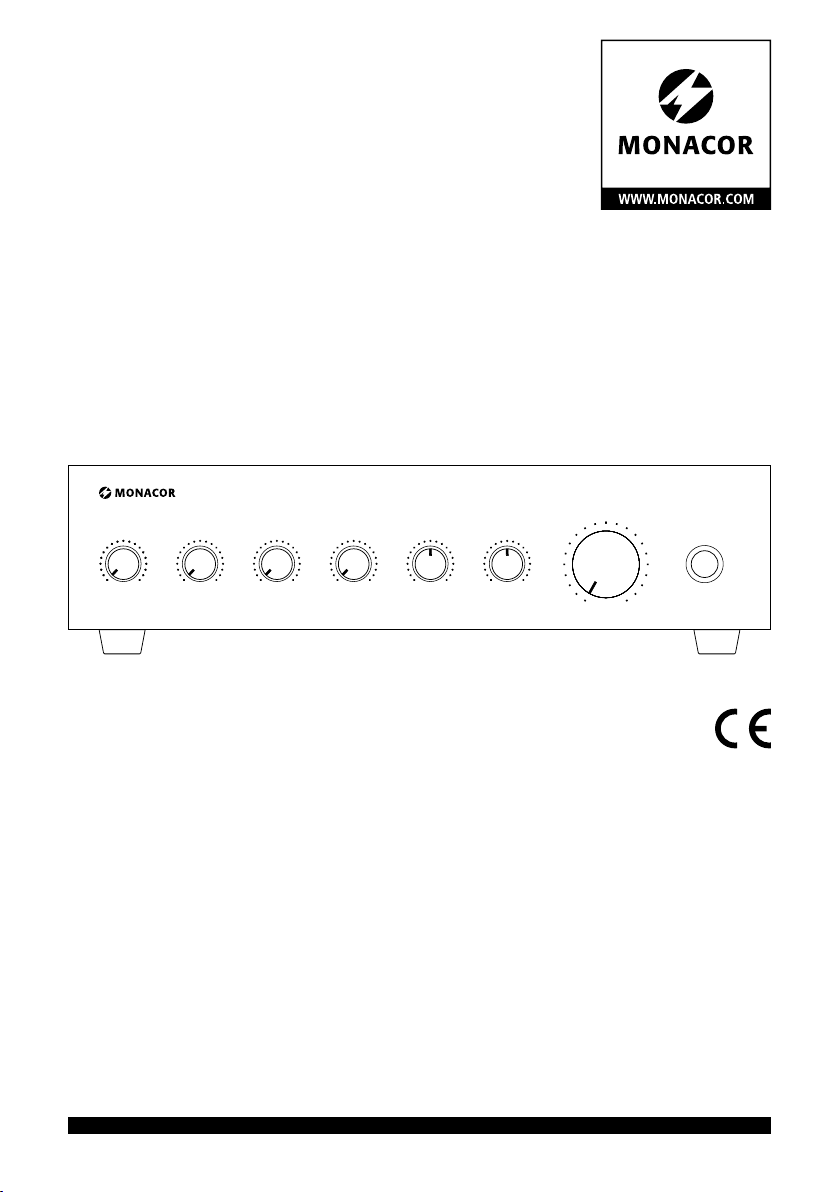
ELA-Mischverstärker
PA Mixing Amplifier
PA-704
MIC 1
MIN MAX MIN
MIC 2
PHONO
MAX
MIN MAX
PA-704
Bestell-Nr. • Order No. 0179480
BEDIENUNGSANLEITUNG
INSTRUCTION MANUAL
MODE D’EMPLOI
10
11
9
8
12
AUX BASS TREBLE POWER
MIN MAX
-10 +10 -10 +10
7
6
5
4
3
2
1
13
14
15
16
17
18
19
20
0
ELECTRONICS FOR SPECIALISTS ELECTRONICS FOR SPECIALISTS ELECTRONICS FOR SPECIALISTS ELECTRONICS FOR SPECIALISTS
Page 2

Deutsch ..........Seite 4
English ...........Page 7
Français ..........Page 10
ELECTRONICS FOR SPECIALISTS ELECTRONICS FOR SPECIALISTS ELECTRONICS FOR SPECIALISTS ELECTRONICS FOR SPECIALISTS
2
Page 3
PA-704
8 97 13 1412 1510 11
(70 V) 100 V 4 Ω
4 Ω 4 Ω
Ω
Ω
Ω
Ω
MIC 1
MIN MAX MIN
MIC 2
10
11
9
8
12
PHONO
MAX
MIN MAX
AUX BASS TREBLE
MIN MAX
-10 +10 -10 +10
7
6
5
4
3
2
1
13
POWER
14
15
16
17
18
19
20
0
2 3 5 61 4
FUSE
230V~ / 5 0Hz
SPEAKER OUTPUTSPRIORITY
COM4Ω8Ω 70V
Beispiele für den Anschluss von Lautsprechern • Examples for connecting speakers
Exemples de branchement de haut-parleurs
SPEAKER OUTPUTSPRIORITY
COM 4Ω 8Ω 70V 100V
+
100 V
(70 V)
-
+
100 V
(70 V)
-
+
100 V
(70 V)
-
max. Nennbelastung
35 W
max. rated load
100 V
(70 V)
. . . .
+
-
➂ ➃
100V
SPEAKER OUTPUTSPRIORITY
COM 4Ω 8Ω 70V 100V
SPEAKER OUTPUTSPRIORITY
COM 4Ω 8Ω 70V 100V
12-24V
AUX
L
R
SPEAKER OUTPUTSPRIORITY
COM 4Ω 8Ω 70V 100V
+
4 Ω
-
8 Ω
+
8 Ω 16 Ω 16 Ω
-
+
8 Ω 8 Ω 16
-
8 Ω
SPEAKER OUTPUTSPRIORITY
COM 4Ω 8Ω 70V 100V
+
-
PHONO
+
-
INPUTS
L
R
+
-
MIC 2 MIC 1
SPEAKER OUTPUTSPRIORITY
COM 4Ω 8Ω 70V 100V
➀
➁
+
16
-
+
-
+
16
-
+
16
-
3
Page 4

ELA-Mischverstärker
Diese Anleitung richtet sich an Installateure für
Beschallungsanlagen (Kapitel 1 – 7) und an Bediener ohne besondere Fachkenntnisse (Kapitel 1 – 3
Deutsch
und Kapitel 6). Bitte lesen Sie die Anleitung vor
dem Betrieb gründlich durch und heben Sie sie
für ein späteres Nachlesen auf.
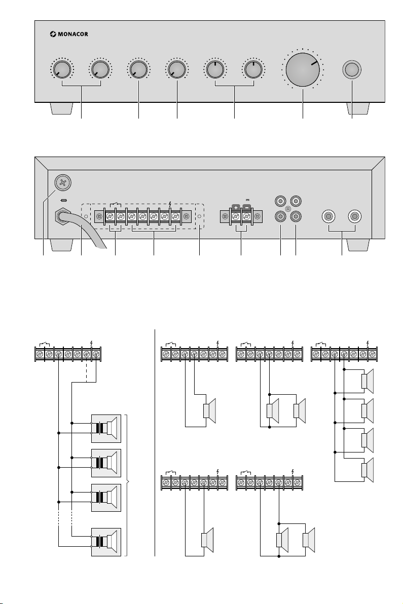
Auf der ausklappbaren Seite3 finden Sie alle
beschriebenen Bedien elemente und Anschlüsse.
1 Übersicht
Frontseite
1
Lautstärkeregler MIC 1 und MIC 2 für die beiden Mikrofoneingänge
2 Lautstärkeregler für den PHONO-Eingang
3 Lautstärkeregler für den AUX-Eingang
4
Klangregler BASS (Tiefen) und TREBLE (Höhen)
5 Regler für die Gesamtlautstärke
6 Ein- /Ausschalter POWER
Rückseite
7
Sicherungshalter; eine geschmolzene Sicherung nur durch eine gleichen Typs ersetzen
8 Netzkabel zum Anschluss an 230 V/ 50 Hz
9 Schraubklemmen PRIORITY für eine Vorrang-
taste (Schließer). Solange die Vorrangtaste
gedrückt wird, ist nur Mikrofon 1 zu hören
(z. B. für wichtige Durchsagen).
10 Schraubklemmen für Lautsprecher
11 Schutzabdeckung für die Schraubklemmen
Vorsicht! Den Verstärker nie ohne die Abdeckung betreiben.
12
Schraubklemmen 12 – 24 V⎓ für eine Notstromversorgung
13
Cinch-Buchsen AUX als Eingang für Geräte mit
Line-Pegel (z. B. CD / MP3-Spieler, KassettenDeck)
14 Cinch-Buchsen PHONO als Eingang für Plat-
tenspieler mit Magnet system
15
6,3-mm-Klinkenbuchsen MIC 1 und MIC 2
für Mikrofone
2 Sicherheitshinweise
Das Gerät entspricht allen relevanten Richtlinien
der EU und ist deshalb mit gekennzeichnet.
WARNUNG Das Gerät wird mit lebensgefähr-
licher Netzspannung versorgt.
Nehmen Sie deshalb niemals selbst
Eingriffe am Gerät vor und stecken
Sie nichts durch die Lüftungsöffnungen! Es be steht die Gefahr
eines elektrischen Schlages.
Im Betrieb liegt an den Lautsprecheranschlüssen(10) berührungsgefährliche Spannung bis
100 V an. Den Verstärker nie ohne die Schutzabdeckung(11) betreiben.
Das Gerät ist nur zur Verwendung im Innenbe-
•
reich geeignet. Schützen Sie es vor Tropf und
Spritzwasser sowie hoher Luftfeuchtigkeit. Der
zulässige Einsatztemperaturbereich beträgt
0 – 40 °C.
Stellen Sie keine mit Flüssigkeit gefüllten Ge-
•
fäße, z. B. Trinkgläser, auf das Gerät.
Die im Gerät entstehende Wärme muss durch
•
Luftzirkulation abgegeben werden. Decken Sie
die Lüftungsöffnungen nicht ab.
Nehmen Sie das Gerät nicht in Betrieb bzw.
•
trennen Sie es sofort von der Stromversorgung:
1. wenn sichtbare Schäden am Gerät oder am
Netzkabel vorhanden sind,
2. wenn nach einem Sturz oder Ähnlichem der
Verdacht auf einen Defekt besteht,
3. wenn Funktionsstörungen auftreten.
Lassen Sie das Gerät in jedem Fall in einer Fachwerkstatt reparieren.
Ein beschädigtes Netzkabel darf nur durch eine
•
Fachwerkstatt ersetzt werden.
Ziehen Sie den Netzstecker nie an am Kabel aus
•
der Steckdose, fassen Sie immer am Stecker an.
Verwenden Sie zum Reinigen nur ein trockenes,
•
weiches Tuch, niemals Wasser oder Chemikalien.
Wird das Gerät zweckentfremdet, falsch ange-
•
schlossen bzw. be dient oder nicht fachgerecht
re pa riert, kann keine Haftung für daraus resultierende Sach- oder Personenschäden und keine
Garantie für das Gerät übernommen werden.
Soll das Gerät endgültig aus dem Betrieb
genommen werden, übergeben Sie es
zur umweltgerechten Entsorgung einem
örtlichen Recyclingbetrieb.
4
Page 5

3 Einsatzmöglichkeiten
Der Verstärker PA-704 mit einer maximalen Ausgangsleistung von 70 W ist für den Einsatz in kleinen ELA-Anlagen konzipiert. Es können entweder 100-V-, 70-V- oder Niederohm-Lautsprecher
verwendet werden (siehe Beispiele Seite 3). Zum
Anschließen von Audioquellen sind 4 Eingänge
vorhanden:
2 Mikrofoneingänge
1 Eingang für Audiogeräte, wie z. B. CD / MP3-
Spieler, Radio oder Tapedeck
1 Eingang für Plattenspieler mit Magnetsystem
4 Aufstellmöglichkeiten
Beim Aufstellen ist darauf zu achten, dass die
Lüftungsschlitze nicht verdeckt werden und Luft
durch das Gerät zur Kühlung zirkulieren kann.
5 Verstärker anschließen
Die Eingänge und die Lautsprecher nur bei ausgeschaltetem Gerät anschließen!
5.1 Eingänge
AUX (13) Anschluss für ein Gerät mit
Line-Ausgang, z. B. CD / MP3Spieler, Kassettendeck oder
Plattenspieler mit Keramiksystem
PHONO (14) Anschluss für einen Plattenspie-
ler mit Magnetsystem
MIC 1 und 2 (15) Anschlüsse für niederohmige
Mikrofone
5.2 Lautsprecher
Zahlreiche Anschlüsse, z. B. die für die Lautsprecher,
befinden sich unter der Schutzabdeckung (11).
Zum Anschließen die Abdeckung abschrauben.
WARNUNG Der Verstärker darf nicht ohne die
Schutzabdeckung (11) betrieben
werden. Im Betrieb liegen an den
Lautsprecheranschlüssen (10) gefährliche Spannungen bis 100 V an. Nach dem
Anschließen die Abdeckung wieder festschrauben, damit die Anschlüsse vor Berührung geschützt sind.
Die Anschlussmöglichkeiten für die Lautsprecher
sind in Abb. 3 und 4 dargestellt. Je nach Gegebenheit sind sie an die Schraubklemmen (10)
anzuschließen. Dabei ist auf die richtige Einzelbzw. Gesamtimpedanz der Lautsprecher und auf
die richtige Polung der Lautsprecher zu achten
(Plus- und Minusanschlüsse, wie in Abb. 3 und 4
gezeigt). Der Plusanschluss der Lautsprecherkabel
ist immer besonders gekennzeichnet.
Achtung! Bei ELA-Lautsprechern mit 70-V- oder
100-V-Audiotransformatoren (Abb. 3) darf die
Gesamtbelastung durch die Lautsprecher nicht
mehr als 35 W Sinus betragen, sonst wird der
Verstärker überlastet. Er kann dann beschädigt
werden.
5.3 Vorrangtaste
An die Schraubklemmen PRIORITY (9) kann eine
Vorrangtaste (Schließer) angeschlossen werden.
Beim Gedrückhalten dieser Vorrangtaste werden
die Kanäle MIC 2, PHONO und AUX ausgeblendet
und es sind nur Durchsagen über MIC 1 zu hören.
Nach dem Loslassen der Vorrangtaste werden die
Kanäle MIC 2, PHONO und AUX wieder eingeblendet.
5.4 Stromversorgung
1) Zum Schluss den Verstärker mit dem Netzkabel(8) an eine Steckdose (230 V/ 50 Hz) anschließen.
2)
Soll der Verstärker bei einem eventuellen
Netzausfall weiterarbeiten, an die Klemmen
12 – 24 V⎓ (12) eine Notstromeinheit (z. B. PA24ESP von MONACOR) anschließen.
Hinweis: Liegt die Spannung von der Notstromeinheit an den Anschlüssen 12 – 24 V⎓ an, lässt sich
der Verstärker mit dem Schalter POWER (6) nicht
ausschalten. Er schaltet bei einem Netzausfall oder
im ausgeschalteten Zustand automatisch auf die
Notstromversorgung um.
6 Bedienung
1)
Vor dem Einschalten den Regler für die Gesamtlautstärke (5) auf Null drehen. Mit dem Schalter
POWER (6) den Verstärker einschalten.
2) Den Regler für die Gesamtlautstärke (5) etwas
aufdrehen. Mit den Reglern MIC 1, MIC 2 (1),
PHONO (2) und AUX (3) die gewünschte Lautstärke untereinander einstellen. Die Regler, an
deren Kanäle kein Gerät angeschlossen ist, auf
Null drehen.
3) Mit den Reglern (4) BASS (Tiefen) und TREBLE
(Höhen) den Klang einstellen sowie mit dem
Regler für die Gesamtlautstärke(5) die Lautstärke.
Deutsch
5
Page 6

4)
Bei Bedarf die Mikrofone mit den Reglern MIC 1
und MIC 2 (1) sowie die Musikquellen mit den
Reglern PHONO (2) und AUX (3) ein- und ausblenden.
Deutsch
5)
Ist eine Vorrangtaste für Mikrofon MIC 1 angeschlossen, diese für Durchsagen gedrückt
halten. Es werden dadurch die Kanäle MIC 2,
PHONO und AUX ausgeblendet und es sind nur
die Durchsagen zu hören. Nach dem Loslassen
der Vorrang taste werden die Kanäle MIC 2,
PHONO und AUX wieder eingeblendet.
7 Technische Daten
Ausgangsleistung, gesamt: . 70 W
Nennleistung: . . . . . . . . . . .35 W
Klirrfaktor: . . . . . . . . . . . . . < 1 %
Ausgänge
Lautsprecher: . . . . . . . . .4 / 8 Ω, 70 /100 V
Eingänge
2 × MIC: . . . . . . . . . . . . .5 mV
1 × PHONO: . . . . . . . . . . 5 mV (RIAA)
1 × AUX: . . . . . . . . . . . . . 210 mV
Frequenzbereich: . . . . . . . .100 – 18 000 Hz
Störabstand: . . . . . . . . . . . . > 55 dB
Stromversorgung
Netzspannung: . . . . . . . . 230V/ 50 Hz
Leistungsaufnahme: . . . . max. 100 VA
Notstromversorgung: . . . ⎓ 12 – 24 V/ 2,5 A
Einsatztemperatur: . . . . . . . 0 – 40 °C
Abmessungen (B × H × T): . 320 × 85 × 230 mm
Gewicht: . . . . . . . . . . . . . . . 4,3 kg
Anschlüsse
MIC 1 und 2: . . . . . . . . . . 6,3-mm-Klinke
AUX und Phono: . . . . . . . Cinch L / R
Lautsprecher: . . . . . . . . . Schraubklemmen
Änderungen vorbehalten.
Diese Bedienungsanleitung ist urheberrechtlich für MONACOR ® INTERNATIONAL GmbH & Co. KG geschützt. Eine
Reproduktion für eigene kommerzielle Zwecke – auch auszugsweise – ist untersagt.
6
Page 7

PA Mixing Amplifier
These instructions are intended for installers of
PA systems (chapters 1 – 7) and for users without
any specific technical knowledge (chapters 1 – 3
and chapter 6). Please read the instructions carefully prior to operation and keep them for later
reference.
All operating elements and connections de-
scribed can be found on the fold-out page 3.
1 Overview
Front panel
1 Volume controls MIC 1 and MIC 2 for both
microphone inputs
2 Volume control for the input PHONO
3 Volume control for the input AUX
4 Tone controls BASS and TREBLE
5 Control to adjust the total volume
6 On / off switch POWER
Rear panel
7
Fuse holder; replace a blown fuse only by one
of the same type
8 Power cable for connection to 230 V/ 50 Hz
9 Screw terminals for a priority switch (NO con-
tact). As long as the priority switch is pressed,
only microphone 1 can be heard (e. g. for important announcements).
10 Screw terminals for speakers
11 Protective cover for the screw terminals
Caution! Never operate the amplifier without
the cover.
12
Screw terminals 12 – 24 V⎓ for an emergency
power supply
13
RCA jacks AUX as input for units with line level
(e. g. CD / MP3 player, cassette deck)
14
RCA jacks PHONO as input for turntables with
magnetic system
15
6.3 mm jacks MIC 1 and MIC 2 for microphones
2 Safety Notes
This unit corresponds to all relevant directives of
the EU and is therefore marked with .
WARNING
During operation, there is a hazard of contact
with a dangerous voltage of up to 100 V at the
speaker terminals (10). Never operate the amplifier without the protective cover (11).
The unit is suitable for indoor use only. Protect
•
it against dripping water, splash water and high
air humidity. The admissible ambient temperature range is 0 – 40 °C.
Do not place any vessel filled with liquid on the
•
unit, e. g. a drinking glass.
The heat generated within the unit must be
•
dissipated by air circulation. Never cover the
air vents.
Do not operate the unit or immediately discon-
•
nect it from the power supply:
1.
if there is visible damage to the unit or to
the mains cable,
2.
if a defect might have occurred after the unit
was dropped or suffered a similar accident,
3. if malfunctions occur.
In any case the unit must be repaired by skilled
personnel.
A damaged mains cable must only be replaced
•
by skilled personnel.
Never pull the mains cable when disconnecting
•
the mains plug from the socket, always seize
the plug.
For cleaning only use a dry, soft cloth; never use
•
chemicals or water.
No guarantee claims for the unit or liability
•
for any resulting personal damage or material
damage will be accepted if the unit is used for
other purposes than originally intended, if it is
not correctly connected or operated, or if it is
not repaired in an expert way.
Important for UK Customers!
•
The wires in this mains lead are coloured in
accord ance with the following code:
The unit is supplied with hazardous
mains voltage. Leave servic ing to
skilled personnel only. Never insert
anything into the air vents. Inexpert handling may result in electric
shock.
English
7
Page 8
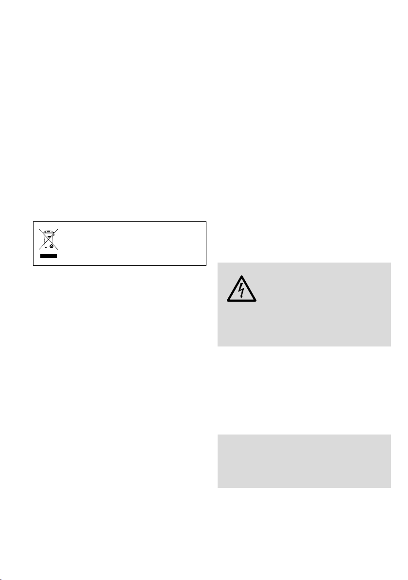
green / yellow = earth
blue = neutral
brown = live
English
As the colours of the wires in the mains lead
of this appliance may not correspond with the
coloured markings identifying the ter minals in
your plug, proceed as follows:
1.
The wire which is coloured green and yellow
must be connected to the terminal in the
plug which is marked with the letter E or
by the earth symbol ⏚ or coloured green or
green and yellow.
2.
The wire which is coloured blue must be connected to the terminal which is marked with
the letter N or coloured black.
3. The wire which is coloured brown must be
con nected to the terminal which is marked
with the letter L or coloured red.
Warning – This appliance must be earthed.
If the unit is to be put out of operation
definitively, take it to a local recycling
plant for a disposal which is not harmful
to the environment.
3 Applications
The amplifier PA-704 provides a maximum output power of 70 W and is specially designed for
small PA systems. 100 V speakers, 70 V speakers or
low-impedance speakers can be used (please refer
to the examples on page 3). For the connection of
audio sources, 4inputs are available:
2 microphone inputs
1 input for audio units, such as CD / MP3 player,
radio or tape deck
1 input for turntables with magnetic system
4 Setup Options
When setting up the amplifier, make sure that
the cooling fins are not covered and that air will
be able to flow freely to ensure sufficient cooling.
5 Connecting the Amplifier
The inputs and speakers may only be connected
when the unit is switched off!
5.1 Inputs
AUX (13) Connection for a unit with line
output, e. g. CD / MP3 player,
tape deck or turntable with
ceramic system
PHONO (14) Connection for a turntable with
magnetic system
MIC 1 and 2 (15) Connections for low-imped-
ance microphones
5.2 Speakers
Numerous connections, e. g. those for the speakers, are underneath the protective cover (11). For
connection, unscrew the cover.
WARNING Do not operate the amplifier with-
out the protective cover (11). During
operation, there is a hazard of con-
tact with a dangerous voltage of up
to 100 V at the speaker terminals (10). After connecting, screw on the cover again so that the
terminals are protected against any accidental
contact.
The speakers can be connected as shown in figs.3
and 4. Connect them to the screw terminals(10)
accordingly. When connecting, observe the correct individual or total impedance of the speakers
and their correct polarity (positive and negative
connections as shown in figs. 3 and 4). The positive connection of the speaker cable is always
specially marked.
Attention! When PA speakers with 70 V or
100 V audio transformers (fig. 3) are used, the
total load of all speakers must not exceed 35 W
RMS; otherwise, the amplifier will be overloaded
and may be damaged.
8
Page 9

5.3 Priority Switch
A priority switch (NO contact) can be connected
to the screw terminals PRIORITY (9). Channels
MIC 2, PHONO and AUX are faded out while this
priority switch is pressed so that only an nouncements via MIC 1 can be heard. After releasing the
priority switch, channels MIC 2, PHONO and AUX
are faded in again.
5.4 Power supply
1) Finally, connect the amplifier by means of the
mains cable(8) to a mains socket (230 V/50 Hz).
2) To ensure continued operation of the amplifier
in case of a mains failure, connect an emergency power supply unit (e. g. PA-24ESP from
MONACOR) to the terminals 12 – 24 V⎓ (12).
Note: If the voltage from the emergency power supply unit is present at the terminals 12 – 24 V⎓, the
amplifier cannot be switched off with the switch
POWER (6). In case of a mains failure or if it is
switched off, the amplifier will switch automatically
to the emergency power supply.
6 Operation
1)
Turn the control for the total volume (5) to zero
before switching on. Switch on the amplifier via
the POWER switch (6).
2)
Slightly turn up the control for the total volume(5). Adjust the desired volume in relation
to each other via the controls MIC 1, MIC 2 (1),
PHONO (2) and AUX (3). Set all controls which
are not connected to a source to zero.
3) Adjust the tone with the controls (4) BASS and
TREBLE and the volume with the control for the
total volume (5).
4)
If desired, fade the microphones in and out
with the controls MIC 1 and MIC 2 (1) as well
as the music sources with the controls PHONO
(2) and AUX (3).
5)
If a priority switch for microphone MIC 1 is connected, keep it pressed during announcements.
Channels MIC 2, PHONO and AUX will be faded
out and only the announcement will be heard.
After releasing the priority switch, channels
MIC 2, PHONO and AUX will be faded in again.
7 Specifications
Total output power: . . . . . . 70 W
Rated power: . . . . . . . . . . . 35 W
THD: . . . . . . . . . . . . . . . . . . < 1 %
Outputs
Speakers: . . . . . . . . . . . . 4 / 8 Ω, 70 / 100 V
Inputs
2 × MIC: . . . . . . . . . . . . .5 mV
1 × PHONO: . . . . . . . . . . 5 mV (RIAA)
1 × AUX: . . . . . . . . . . . . . 210 mV
Frequency range: . . . . . . . . 100 – 18 000 Hz
S / N ratio: . . . . . . . . . . . . . . > 55 dB
Power supply
mains voltage: . . . . . . . . . 230 V/ 50 Hz
power consumption: . . . . 100 VA max.
emergency power supply: ⎓ 12 – 24 V/ 2.5 A
Ambient temperature: . . . .0 – 40 °C
Dimensions (W × H × D): . . 320 × 85 × 230 mm
Weight: . . . . . . . . . . . . . . .4.3 kg
Connections
MIC 1 and 2: . . . . . . . . . . 6,3 mm jack
AUX and Phono: . . . . . . .RCA L / R
Speakers: . . . . . . . . . . . . screw terminals
Subject to technical modification.
English
All rights reserved by MONACOR ® INTERNATIONAL GmbH & Co. KG. No part of this instruction manual may be
reproduced in any form or by any means for any commercial use.
9
Page 10

Amplificateur mixeur Public Adress
Cette notice s’adresse aux installateurs d’installations de sonorisation (chapitres 1 – 7) et aux
utilisateurs sans connaissances techniques parti-
Français
culières (chapitres 1 – 3 et chapitre 6). Veuillez lire
la présente notice avec attention avant le fonctionnement et conservez-la pour pouvoir vous y
reporter ultérieurement.
Vous trouverez sur la page 3, dépliable, les
éléments et branchements décrits.
1 Présentation
Face avant
1 Réglages de volume MIC 1 et MIC 2 pour les
deux entrées micro
2 Réglage de volume pour l’entrée PHONO
3 Réglage de volume pour l’entrée AUX
4 Réglages de tonalité BASS (graves) et TREBLE
(aigus)
5 Réglage du volume général
6 Interrupteur Marche /Arrêt POWER
Face arrière
7
Porte-fusible : tout fusible fondu doit être remplacé par un fusible de même type.
8 Câble secteur 230 V/ 50 Hz
9 Bornes à vis PRIORITY pour touche de priorité
(contact à fermeture). Tant que la touche de
priorité est enfoncée, on ne peut entendre
que le micro1 (par exemple pour une annonce
importante).
10 Bornes à vis pour les haut-parleurs
11 Couvercle de protection pour les bornes à vis
Attention ! Ne faites jamais fonctionner l’amplificateur sans le couvercle !
12
Bornes à vis 12 – 24 V⎓ pour une alimentation
de secours
13
Prises RCA AUX, entrée pour les appareils
à niveau Line (par exemple un lecteur de
CD / MP3, de cassettes)
14
Prises RCA PHONO, entrée pour une platine-disques à cellule magnétique
15
Prises jack 6,35 MIC 1 et MIC 2 pour les micros
10
2 Conseils de sécurité
L’appareil répond à toutes les directives nécessaires de l’Union européenne et porte donc le
symbole .
AVERTISSEMENT L’appareil est alimenté par une
tension dangereuse. Ne touchez jamais l’intérieur de l’appareil et ne faites rien tomber
dans les ouïes de ventilation
car, en cas de mauvaise manipulation, vous pouvez subir une
décharge électrique.
Pendant le fonctionnement, une tension dangereuse jusqu’à 100 V est présente aux bornes
haut-parleurs (10). Ne faites jamais fonctionner l’amplificateur sans le couvercle de protection(11).
L’appareil n’est conçu que pour une utilisation
•
en intérieur. Protégez-le des éclaboussures, de
tout type de projections d’eau et d’une humidité élevée de l’air. La température ambiante
admissible est de 0 – 40 °C.
En aucun cas, vous ne devez poser d’objet
•
contenant du liquide ou un verre sur l’appareil.
La chaleur dégagée par l’appareil doit être
•
évacuée par une circulation d’air correcte. En
aucun cas, les ouïes de ventilation ne doivent
être obturées.
Ne le faites jamais fonctionner et débranchez-le
•
immédiatement de l’alimentation dans les cas
suivants :
1.
des dommages sur l’appareil ou sur le cordon
secteur apparaissent.
2.
après une chute ou accident similaire..., l’appareil peut présenter un défaut.
3. des dysfonctionnements apparaissent.
Dans tous les cas, les dommages doivent être
réparés par un technicien spécialisé.
Tout cordon secteur endommagé ne doit être
•
remplacé que par un technicien spécialisé.
Ne débranchez jamais l’appareil en tirant sur
•
le cordon secteur ; retirez toujours le cordon
secteur en tirant la fiche.
Pour nettoyer l’appareil, utilisez uniquement un
•
chiffon sec et doux, en aucun cas de produits
chimiques ou d’eau.
Nous déclinons toute responsabilité en cas de
•
dommages corporels ou matériels résultants
si l’appareil est utilisé dans un but autre que
Page 11

celui pour lequel il a été conçu, s’il n’est pas
correctement branché ou utilisé ou s’il n’est pas
réparé par une personne habilitée ; de même,
la garantie deviendrait caduque.
Lorsque l’appareil est définitivement
retiré du service, vous devez le déposer
dans une usine de recyclage de proximité pour contribuer à son élimination
non polluante.
CARTONS ET EMBALLAGE
PAPIER À TRIER
3 Possibilités d'utilisation
L’amplificateur PA-704 avec une puissance de
sortie maximale de 70 W est conçu pour une utilisation dans de petites installations Public Adress.
Il est possible d’utiliser des enceintes 100 V, 70 V
ou basse impédance (voir exemples page 3). Pour
relier les sources audio, 4 entrées sont prévues :
2 entrées micro
1 entrée pour appareils audio, par exemple lecteur
CD / MP3, radio ou tapedeck
1 entrée pour platine-disques à cellule magnétique
5.2 Haut-parleurs
De nombreux branchements, par exemple pour
les haut-parleurs, se trouvent sous le couvercle
de protection (11). Dévissez-le pour effecteur les
branchements.
AVERTISSEMENT
L’amplificateur ne doit pas
fonctionner sans le couvercle
de protection (11). Pendant le
fonctionnement, des tensions
dangereuses, jusqu’à 100 V, sont présentes
aux connexions haut-parleurs (10). Une fois les
branchements effectués, revissez solidement le
couvercle afin de protéger les connexions de
tout contact.
Les schémas 3 et 4 indiquent les diverses possibilités de branchement des haut-parleurs. Selon les
cas, il faut relier ces derniers aux bornes à vis (10).
Veillez à respecter l’impédance de chaque hautparleur et de l’ensemble ainsi que la polarité des
haut-parleurs (branchements plus et moins comme
indiqué sur les schémas 3 et 4). Le branchement
plus du câble haut-parleur est toujours repéré.
Attention ! Pour des haut-parleurs PA avec
transformateur audio 70 V ou100 V (schéma 3),
la charge totale ne doit pas être supérieure à
35 W RMS ; sinon l’amplificateur serait en surcharge et pourrait être endommagé.
Français
4 Possibilités d’installation
Lors de l’installation, veillez à ce que les ouïes d’aération ne soient pas obturées et que l’air puisse
correctement circuler dans l’appareil pour assurer
un refroi dissement optimal.
5 Branchements
Vous ne devez effectuer les branchements que
lorsque l’appareil est débranché.
5.1 Entrées
AUX (13) branchement pour un appareil
avec entrée Line (par exemple,
un lecteur CD / MP3, de cassettes ou une platine-disques
avec cellule céramique)
PHONO (14) branchement pour une platine-
disques avec cellule magnétique
MIC 1 et 2 (15) branchement pour des micros
basse impédance
5.3 Touche priorité
Vous pouvez relier une touche de priorité (contact
à fermeture) aux bornes à vis PRIORITY (9). Lorsque
vous maintenez cette touche enfoncée, vous pouvez effectuer des annonces par le canal MIC 1,
les trois autres canaux MIC 2, PHONO et AUX ne
fonctionnent pas. Une fois que vous relâchez la
touche de priorité, les canaux MIC 2, PHONO et
AUX sont de nouveau actifs.
5.4 Alimentation
1)
Vous pouvez maintenant relier l’amplificateur avec le cordon secteur (8) au secteur
230 V/ 50 Hz.
2) Si l’amplificateur doit continuer à travailler en
cas de coupure de courant, reliez aux bornes
12 – 24 V⎓ (12) une alimentation de secours
(p. ex. PA-24ESP de MONACOR).
Remarque : Si une tension de l’unité d’alimentation
de secours est présente aux bornes 12 – 24 V⎓, l’amplificateur ne peut pas être éteint avec l’interrupteur
POWER (6). En cas de coupure de courant ou s’il est
éteint, l’amplificateur commute automatiquement
sur l’alimentation de secours.
11
Page 12

6 Utilisation
1)
Avant d’allumer l’amplificateur, mettez le
réglage pour le volume général (5) sur zéro.
Allumez ensuite l’amplificateur avec l’interrup-
Français
teur Marche /Arrêt (6).
2)
Tournez un peu le réglage pour le volume général (5) ; réglez le volume avec les réglages MIC 1,
MIC 2 (1), PHONO (2) et AUX (3). Mettez sur
zero les réglages des canaux auxquels aucun
appareil n’est relié.
3)
Utilisez les réglages (4) BASS (graves) et TREBLE
(aigus) pour régler la tonalité et le réglage (5)
pour régler le volume général.
4) Vous pouvez effectuer un fondu-enchaîné des
micros avec les réglages MIC 1 et MIC 2 (1)
et des sources de musique avec les réglages
PHONO (2) et AUX (3).
5)
Si une touche de priorité est reliée au micro
MIC 1, vous devez la maintenir enfoncée pour
effectuer une annonce micro. Seule l’annonce
est entendue, les canaux MIC 2, PHONO et AUX
sont coupés. Une fois que vous avez relâché la
touche priorité, les canaux MIC 2, PHONO et
AUX sont de nouveau actifs.
7 Caractéristiques techniques
Puissance de sortie, totale : . 70 W
Puissance nominale : . . . . . . 35 W
Taux de distorsion : . . . . . . . < 1 %
Sorties
Haut-parleurs : . . . . . . . . 4 / 8 Ω, 70 / 100 V
Entrées
2 × MIC : . . . . . . . . . . . .5 mV
1 × PHONO : . . . . . . . . . . 5 mV (RIAA)
1 × AUX : . . . . . . . . . . . . 210 mV
Bande passante : . . . . . . . . . 100 – 18 000 Hz
Rapport signal / bruit : . . . . . > 55 dB
Alimentation
Tension secteur : . . . . . . . 230 V/ 50 Hz
Consommation : . . . . . . .100 VA max.
Alimentation de secours : ⎓ 12 – 24 V/ 2,5 A
Température de fonc.: . . . . . 0 – 40 °C
Dimensions (l × h × p) : . . . . 320 × 85 × 230 mm
Poids : . . . . . . . . . . . . . . . . . 4,3 kg
Branchements
MIC 1 et 2: . . . . . . . . . . . jack 6,35
AUX et Phono: . . . . . . . . RCA D / G
Haut-parleurs: . . . . . . . . . bornes à vis
Tout droit de modification réservé.
Notice d’utilisation protégée par le copyright de MONACOR ® INTERNATIONAL GmbH & Co. KG. Toute reproduction
même partielle à des fins commerciales est interdite.
12
Page 13

Page 14

MONACOR INTERNATIONAL GmbH & Co. KG • Zum Falsch 36 • 28307 Bremen • Germany
Copyright © by MONACOR INTERNATIONAL. All rights reserved. A-2028.99.01.12.2019
 Loading...