

Page 1

PA -312
Bestellnummer 17.3640
ELA-MISCHVERSTÄRKER
PA MIXING AMPLIFIER
BEDIENUNGSANLEITUNG
INSTRUCTION MANUAL
MODE D’EMPLOI
ISTRUZIONI PER L’USO
GEBRUIKSAANWIJZING
MANUAL DE INSTRUCCIONES
INSTRUKCJA OBSŁUGI
SIKKERHEDSOPLYSNINGER
SÄKERHETSFÖRESKRIFTER
TURVALLISUUDESTA
Page 2

2
Bevor Sie einschalten …
Wir wünschen Ihnen viel Spaß mit Ihrem neuen Gerät
von MONACOR. Bitte lesen Sie diese Bedienungsanleitung vor dem Betrieb gründlich durch. Nur so lernen Sie
alle Funktionsmöglichkeiten kennen, vermeiden Fehlbedienungen und schützen sich und Ihr Gerät vor eventuellen Schäden durch unsachgemäßen Gebrauch. Heben
Sie die Anleitung für ein späteres Nachlesen auf.
Der deutsche Text beginnt auf der Seite 4.
Before switching on …
We wish you much pleasure with your new MONACOR
unit. Please read these operating instructions carefully
prior to operating the unit. Thus, you will get to know all
functions of the unit, operating errors will be prevented,
and yourself and the unit will be protected against any
damage caused by improper use. Please keep the oper ating instructions for later use.
The English text starts on page 6.
Avant toute installation …
Nous vous souhaitons beaucoup de plaisir à utiliser cet
appareil MONACOR. Lisez ce mode dʼemploi entièrement avant toute utilisation. Uniquement ainsi, vous pourrez apprendre lʼensemble des possibilités de fonctionnement de lʼappareil, éviter toute manipulation erronée et
vous protéger, ainsi que lʼappareil, de dommages éventuels engendrés par une utilisation inadaptée. Conservez
la notice pour pouvoir vous y reporter ultérieurement.
La version française se trouve page 8.
Prima di accendere …
Vi auguriamo buon divertimento con il vostro nuovo
apparecchio di MONACOR. Leggete attentamente le
istruzioni prima di mettere in funzione lʼapparecchio.
Solo così potete conoscere tutte le funzionalità, evitare
comandi sbagliati e proteggere voi stessi e lʼapparecchio
da eventuali danni in seguito ad un uso improprio. Conservate le istruzioni per poterle consultare anche in
futuro.
Il testo italiano inizia a pagina 10.
D
A
CH
GB
Voor u inschakelt …
Wij wensen u veel plezier met uw nieuwe apparaat van
MONACOR. Lees deze gebruikershandleiding grondig
door, alvorens het apparaat in gebruik te nemen. Alleen
zo leert u alle functies kennen, vermijdt u foutieve be diening en behoedt u zichzelf en het apparaat voor eventuele schade door ondeskundig gebruik. Bewaar de
handleiding voor latere raadpleging.
De Nederlandstalige tekst vindt u op pagina 12.
Før du tænder …
Tillykke med dit nye MONACOR produkt. Læs sikkerhedsanvisningerne nøje før ibrugtagning, for at beskytte
Dem og enheden mod skader, der skyldes forkert brug.
Gem venligst denne betjeningsvejledning til senere brug.
Sikkerhedsanvisningerne findes på side 18.
Innan du slår på enheten …
Vi önskar dig mycket glädje med din nya MONACOR
produkt. Läs igenom säkerhetsföre skrifterna innan en heten tas i bruk för att undvika skador till följd av felaktig
hantering. Behåll instruktionerna för framtida bruk.
Säkerhetsföreskrifterna återfinns på sidan 18.
Ennen kytkemistä …
Toivomme Sinulle paljon miellyttäviä hetkiä uuden
MONACOR laitteen kanssa. Ennen laitteen käyttöä pyydämme Sinua huolellisesti tutustumaan turvallisuusohjeisiin. Näin vältyt vahingoilta, joita virheellinen laitteen
käyttö saattaa aiheuttaa. Ole hyvä ja säilytä käyttöohjeet
myöhempää tarvetta varten.
Turvallisuusohjeet löytyvät sivulta 19.
F
B
CH
I
Antes de la utilización …
Le deseamos una buena utilización para su nue vo aparato MONACOR. Por favor, lea estas in s trucciones de
uso atentamente antes de ha cer funcionar el aparato. De
esta manera conocerá todas las funciones de la unidad,
se pre vendrán errores de operación, usted y el apa rato
estarán protegidos en contra de todo daño cau sado por
un uso inadecuado. Por favor, guarde las instrucciones
para una futura utilización.
La versión española comienza en la página 14.
E
NL
Przed uruchomieniem …
Życzymy zadowolenia z nowego produktu MONACOR.
Dzięki tej instrukcji obsługi będą państwo w stanie
poznać wszystkie funkcje tego urządzenia. Stosując się
do instrukcji unikną państwo błędów i ewentualnego
uszkodzenia urządzenia na skutek nieprawidłowego
użytkowania. Prosimy zachować instrukcję.
Tekst polski zaczyna się na stronie 16.
PL
DK
S FIN
B
Page 3
3
12 3 4 567 1
8 9 10 11 12 13 14 15 16 17
Page 4
Auf der ausklappbaren Seite 3 finden Sie
alle beschriebenen Bedienelemente und An schlüsse.
1 Hinweise für den
sicheren Gebrauch
Das Gerät entspricht allen relevanten Richtlinien
der EU und ist deshalb mit gekennzeichnet.
Beachten Sie auch unbedingt die folgenden
Punkte:
G
Das Gerät ist nur zur Verwendung im Innenbe reich geeignet. Schützen Sie es vor Tropfund Spritzwasser, hoher Luftfeuchtigkeit und
Hitze (zulässiger Einsatztemperaturbereich
0 – 40°C).
G
Stellen Sie keine mit Flüssigkeit gefüllten Ge fäße, z. B. Trinkgläser, auf das Gerät.
G
Nehmen Sie das Gerät nicht in Betrieb und
ziehen Sie sofort den Netzstecker aus der
Steckdose,
1. wenn sichtbare Schäden am Gerät oder am
Netzkabel vorhanden sind,
2. wenn nach einem Sturz oder Ähnlichem der
Verdacht auf einen Defekt besteht,
3. wenn Funktionsstörungen auftreten.
Geben Sie das Gerät in jedem Fall zur Reparatur in eine Fachwerkstatt.
G
Ziehen Sie den Netzstecker nie am Kabel aus
der Steckdose, fassen Sie immer am Stecker
an.
G
Verwenden Sie für die Reinigung nur ein trockenes, weiches Tuch, niemals Wasser oder
Chemikalien.
G
Wird das Gerät zweckentfremdet, nicht richtig
angeschlossen, falsch be dient oder nicht fachgerecht repariert, kann keine Haftung für
daraus resultierende Sach- oder Personenschäden und keine Garantie für das Gerät
übernommen werden.
2 Einsatzmöglichkeiten
Dieser Verstärker mit einer Sinusausgangsleistung von 120 W ist speziell für den Einsatz in
ELA-Anlagen konzipiert. Es können entweder
100-V- bzw. 70-V-Lautsprecher oder Niederohmlautsprecher (Impedanz min. 4 Ω) verwendet werden.
Der Verstärker ist mit 6 Eingängen ausgestattet:
1 × Line-Pegel-Eingang TEL INPUT für wichtige
Durchsagen (z. B. von einer Telefonzentrale) mit Vorrang vor allen anderen Eingängen, d. h. sobald ein Signal an dem Eingang
anliegt, werden die Signale der anderen Eingänge ausgeblendet
1 × Mikrofoneingang MIC 1 für wichtige Durch-
sagen mit Vorrang vor den Eingängen
MIC 2, MIC 3, INPUT 4 und INPUT 5, d. h.
sobald ein Signal am Eingang MIC 1 anliegt,
werden die Signale der untergeordneten
Eingänge in der Lautstärke reduziert
2 × Mikrofoneingänge MIC 2 und MIC 3
2 × Line-Pegel-Eingänge INPUT 4 und INPUT 5
z. B. für Hintergrundmusik von einem MP3 /
CD-Spieler, Radio oder Tape-Deck
3 Aufstellen des Verstärkers
Der Verstärker ist für den Einschub in ein Rack
für Geräte mit einer Breite von 482 mm (19″)
vorgesehen, kann aber auch als Tischgerät verwendet werden. In jedem Fall muss Luft ungehindert durch alle Lüftungsöffnungen strömen
können, damit eine ausreichende Kühlung des
Verstärkers gewährleistet ist.
3.1 Rackeinbau
Zum Einbau in ein Rack die beiden Montagewinkel (1) seitlich am Verstärker festschrauben. Der
Verstärker benötigt im Rack einen Platz von
2 HE (2 Höheneinheiten = 89 mm). Damit das
Rack nicht kopflastig wird, muss der Verstärker
im unteren Bereich des Racks eingeschoben
werden. Für eine sichere Befestigung reichen
die Montagewinkel allein nicht aus. Zusätzlich
müssen Seitenschienen oder eine Bodenplatte
das Gerät halten.
Die vom Verstärker abgegebene erhitzte Luft
muss aus dem Rack austreten können. Anderenfalls kommt es im Rack zu einem Hitze stau,
wodurch nicht nur der Verstärker, sondern auch
andere Geräte im Rack beschädigt werden können. Bei unzureichendem Wärmeabfluss in das
Rack eine Lüftereinheit einsetzen.
4 Bedienelemente und
Anschlüsse
4.1 Vorderseite
1 Montagewinkel (2 ×) zum Einbau des Ver-
stärkers in ein Rack für Geräte mit einer
Breite von 482 mm (19″)
2 Eingang MIC 1 (6,3-mm-Klinke, asym.) zum
An schluss eines Mikrofons
Die Buchse ist parallelgeschaltet mit der
Buchse MIC 1 (12) auf der Rückseite, kann
jedoch keine Phantomspeisung liefern.
Der Eingang MIC 1 ist mit einer Vorrangschaltung ausgestattet: Bei einer Durchsage
über diesen Eingang werden die Eingänge
MIC 2, MIC 3 (14), INPUT 4 und INPUT 5 (16)
automatisch in der Lautstärke verringert, um
die Verständlichkeit der Durchsage zu verbessern. Die Höhe der Lautstärkeverringerung lässt sich mit dem Regler MUTE LEVEL
(11) einstellen.
3 Eingangspegelregler zum Mischen oder Ein-
und Ausblenden der Eingangssignale
4 Klangregler BASS und TREBLE
5 Regler MASTER für die Lautstärke des
Mischsignals an den Line- und Lautsprecherausgängen (17, 10)
6 Ausgangspegelanzeige,
Anzeige TEMP für Überhitzung,
Anzeige PROT für Kurzschluss oder Überlastung der Lautsprecherausgänge (10)
Leuchtet die Übersteuerungsanzeige CLIP
nicht nur kurz auf, den Regler MASTER (5)
oder den entsprechenden Eingangsregler (3)
zurückdrehen.
Leuchtet die Anzeige TEMP auf, muss der
Verstärker besser belüftet werden. Sobald der
Verstärker abgekühlt ist, erlischt die Anzeige
TEMP wieder.
Leuchtet die Anzeige PROT auf, den Verstärker ausschalten und die Überlast oder
den Kurzschluss an den Lautsprecherausgängen beseitigen. Die Anzeige PROT er lischt danach wieder. Kann die Fehlerursache
nicht gefunden werden, Fachpersonal zur
Hilfe nehmen.
7 Ein-/Ausschalter POWER mit darüberliegen-
der Betriebsanzeige ON
Soll das Gerät endgültig aus dem Be trieb genommen werden, übergeben
Sie es zur umweltgerechten Entsorgung einem örtlichen Recyclingbetrieb.
WARNUNG Das Gerät wird mit lebensge -
fährlicher Netzspannung versorgt.
Nehmen Sie deshalb nie selbst
Eingriffe am Gerät vor und stecken
Sie nichts durch die Lüftungsöffnungen! Es besteht die Gefahr
eines elektrischen Schlages.
Im Betrieb liegt an den Lautsprecheranschlüssen (10) berührungsgefährliche Spannung bis
100 V an. Betreiben Sie den Verstärker nur mit
heruntergeklappter Schutzabdeckung.
Führen Sie alle Anschlüsse nur bei ausgeschaltetem Verstärker durch.
4
D
A
CH
Page 5

Diese Bedienungsanleitung ist urheberrechtlich für MONACOR®INTERNATIONAL GmbH & Co. KG
geschützt. Eine Reproduktion für eigene kommerzielle Zwecke – auch auszugsweise – ist untersagt.
4.2 Rückseite
8 Netzbuchse zum Anschluss an eine Steck-
dose (230 V~/50 Hz) über das beiliegende
Netzkabel
9 Halterung für die Netzsicherung
Eine geschmolzene Sicherung nur durch eine
gleichen Typs ersetzen.
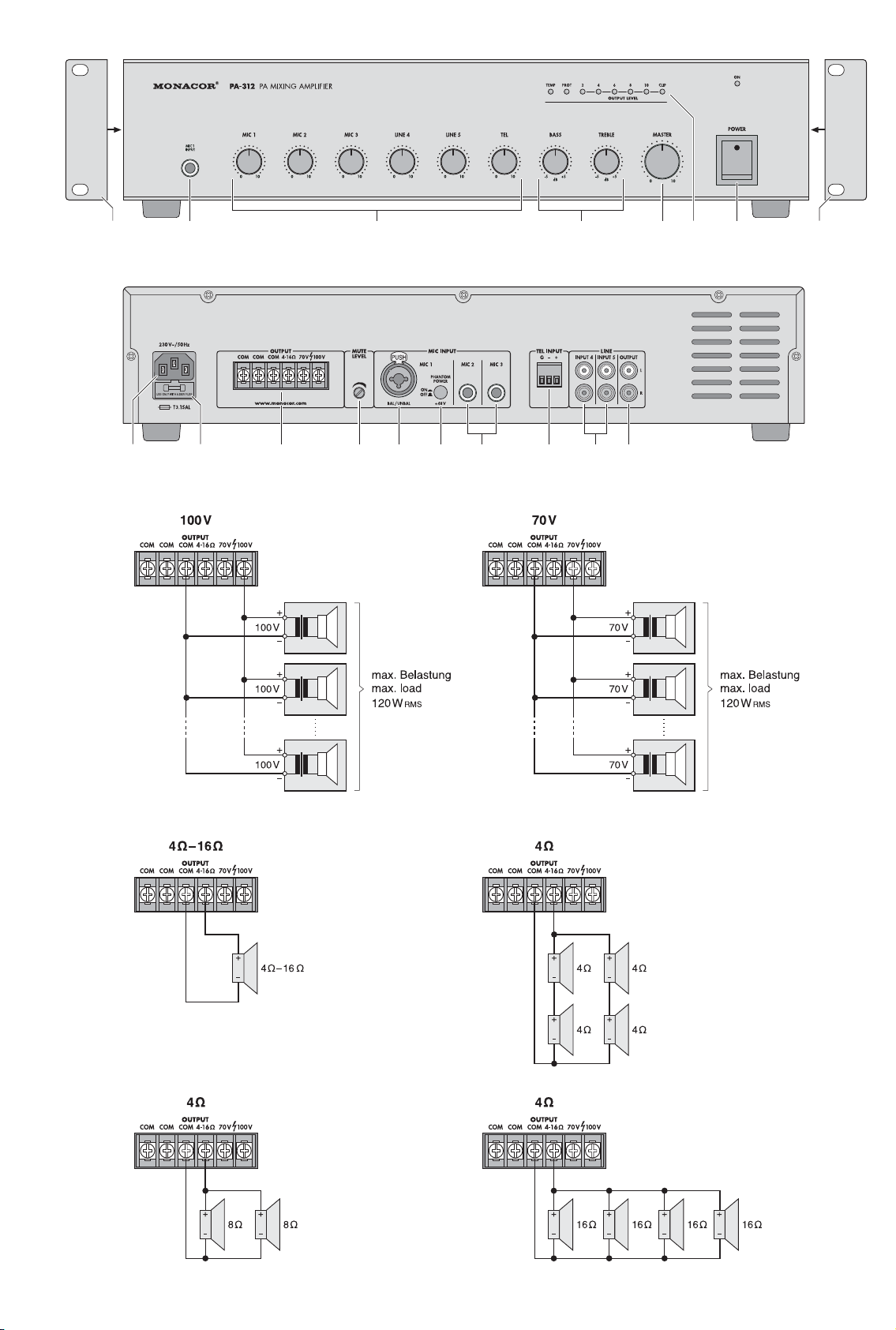
10 Lautsprecheranschlüsse mit transparenter
Schutzabdeckung, zum Anschluss der Lautsprecher die Abdeckung nach oben klappen
Anschlussbeispiele siehe Abb. 3 – 8
Entweder 100-V- oder 70-V-Lautsprecher an
die Klemmen „70 V“ oder „100 V“ und „COM“
anschließen (Abb. 3, 4); der Verstärker darf
mit maximal 120 W durch die Lautsprecher
belastet werden, anderenfalls kann er be schädigt werden
oder einen Lautsprecher bzw. eine Lautsprechergruppe mit einer Gesamtimpedanz von
mindestens 4 Ω an die Klemmen „4-16 Ω“
und „COM“ anschließen. Die Abbildungen 5
bis 8 zeigen verschiedene Arten, die Mindestimpedanz einzuhalten. Es gibt aber noch
weitere Möglichkeiten.
11 Regler MUTE LEVEL zum Einstellen der
Höhe der Lautstärkeabsenkung für die Eingänge MIC 2, MIC 3 (14), INPUT 4 und
INPUT 5 (16), wenn über den Eingang MIC 1
(2, 12) eine Durchsage erfolgt
12 Eingang MIC 1 (XLR / 6,3-mm-Klinken-Kombi-
buchse, sym.) zum Anschluss eines Mikrofons; für ein phantomgespeistes Mikrofon die
Taste PHANTOM POWER (13) hineindrücken
Die Buchse ist parallelgeschaltet mit der
Buchse MIC 1 (2) auf der Vorderseite. Zur
Vorrangschaltung des Eingangs MIC 1 siehe
Position 2.
13 Taste PHANTOM POWER zum Einschalten
der 48-V-Phantomspeisung für die Buchse
MIC 1 (12) auf der Rückseite
[Die Buchse MIC 1 (2) auf der Vorderseite
kann keine Phantomspeisung liefern.]
14 Eingänge MIC 2 und MIC 3 (6,3-mm-Klinke,
asym.) zum Anschluss von Mikrofonen
15 Eingang TEL INPUT (Steckschraubklemme)
zum Anschluss einer Telefonzentrale mit LinePegel-Ausgang oder einer anderen Line-Signalquelle für wichtige Durchsagen
Sobald ein Signal an diesem Eingang anliegt,
werden die Signale der anderen Eingänge
ausgeblendet.
Die Klemme lässt sich zur leichteren Handhabung beim Anschließen aus ihrer Steckverbindung herausziehen.
16 Eingänge INPUT 4 und INPUT 5 (6,3-mm-
Klinke, asym.) zum Anschluss von Audiogeräten mit Line-Ausgang (MP3 / CD-Spieler,
Radio, Tape-Deck etc.)
17 Line-Ausgang OUTPUT für das Mischsignal
zum Anschluss z. B. eines zusätzlichen Verstärkers, wenn mehr Lautsprecher benötigt
werden, als der PA-312 betreiben kann
5 Technische Daten
Ausgangsleistung: . . . . . 120 WRMS, 160WMAX
Klirrfaktor: . . . . . . . . . . . . < 0,5 %
Ausgänge
Lautsprecher: . . . . . . . 4 – 16Ω, 70 / 100V
LINE: . . . . . . . . . . . . . . 0,775 V/ 600 Ω
Eingänge
Empfindlichkeit / Impedanz; Anschluss
MIC 1: . . . . . . . . . . . . . 5 mV/ 600 Ω;
1 × XLR / 6,3-mmKlinke, symmetrisch
1 × 6,3-mm-Klinke,
asymmetrisch
MIC 2, MIC 3: . . . . . . . 5 mV/ 600 Ω;
6,3-mm-Klinke,
asymmetrisch
INPUT 4, INPUT 5: . . . 350 mV/ 10 kΩ;
Cinch
TEL INPUT: . . . . . . . . . 1 V/10kΩ; Schraub-
anschlüsse, sym.
Phantomspannung
für MIC 1: . . . . . . . . . . . . 48 V , zuschaltbar
Frequenzbereich: . . . . . . 50 – 16000 Hz
Klangregler
Tiefen: . . . . . . . . . . . . . ±10 dB / 100 Hz
Höhen: . . . . . . . . . . . . . ±10 dB / 10 kHz
Störabstand
MIC 1 – 3: . . . . . . . . . . 66 dB
TEL, INPUT 4 + 5: . . . . 80 dB
Stromversorgung: . . . . . . 230 V~/ 50 Hz
Leistungsaufnahme: . . . . max. 450 VA
Einsatztemperatur: . . . . . 0 –40 °C
Abmessungen: . . . . . . . . 430 × 88 × 335 mm,
2HE
Gewicht: . . . . . . . . . . . . . 7,8 kg
Änderungen vorbehalten.
Vorsicht! Bei eingeschalteter Phantomspannung kein Mikrofon mit asymmetrischem Ausgang anschließen, da dieses
beschädigt werden kann.
WARNUNG Betreiben Sie das Gerät nur
mit heruntergeklappter Abdeckung. Anderenfalls kann es
beim Berühren der Anschlüsse
durch die hohe Spannung zu
einem gefährlichen elektrischen Schlag kommen.
5
D
A
CH
Page 6
All operating elements and connections de scribed can be found on the fold-out page 3.
1 Safety Notes
This unit corresponds to all relevant directives of
the EU and is therefore marked with .
Please observe the following items in any case:
G
The unit is suitable for indoor use only. Protect
it against dripping water and splash water,
high air humidity and heat (admissible ambient temperature range: 0 – 40°C).
G
Do not place any vessel filled with liquid on the
unit, e. g. a drinking glass.
G
Do not operate the unit and immediately disconnect the mains plug from the socket
1. if the unit or the mains cable is visibly damaged,
2. if a defect might have occurred after the unit
was dropped or suffered a similar accident,
3. if malfunctions occur.
In any case the unit must be repaired by
skilled personnel.
G
Never pull the mains cable to disconnect the
mains plug from the socket, always seize the
plug.
G
For cleaning only use a dry, soft cloth; never
use water or chemicals.
G
No guarantee claims for the unit and no liability for any resulting personal damage or material damage will be accepted if the unit is used
for other purposes than originally intended, if it
is not correctly connected or operated, or if it
is not repaired in an expert way.
G
Important for U. K. Customers!
The wires in this mains lead are coloured in
accordance with the following code:
green/yellow = earth
blue = neutral
brown = live
As the colours of the wires in the mains lead of
this appliance may not correspond with the
coloured markings identifying the terminals in
your plug, proceed as follows:
1. The wire which is coloured green and yellow must be connected to the terminal in the
plug which is marked with the letter E or by
the earth symbol , or coloured green or
green and yellow.
2. The wire which is coloured blue must be
connected to the terminal which is marked
with the letter N or coloured black.
3. The wire which is coloured brown must be
connected to the terminal which is marked
with the letter L or coloured red.
Warning – This appliance must be earthed.
2 Applications
This amplifier with a 120 W RMS output voltage
is specially designed for PA systems. Either use
100 V or 70 V speakers or low resistance speakers (minimum impedance 4 Ω).
The amplifier is equipped with 6 inputs:
1 × line level input TEL INPUT for important an -
nouncements (e. g. from a telephone system) taking priority over all other inputs, i. e.
with a signal present at the input, the signals
of the other inputs will be faded out
1 × microphone input MIC 1 for important an -
nouncements taking priority over the inputs
MIC 2, MIC 3, INPUT 4 and INPUT 5,
i. e. with a signal present at the input MIC 1,
the volume of the signals at the inputs of
lower priority will be attenuated
2 × microphone inputs MIC 2 and MIC 3
2 × line level inputs INPUT 4 and INPUT 5, e. g.
for background music from an MP3 / CD
player, radio or tape deck
3 Setting Up the Amplifier
The amplifier is designed for installation into a
rack for units of a width of 482 mm (19″); however, it is also suitable as a tabletop unit. In order
to ensure a sufficient cooling of the amplifier, air
must always be able to flow freely through all air
vents.
3.1 Rack installation
For rack installation, fasten the two mounting
brackets (1) with screws to the sides of the
amplifier. In the rack, the amplifier requires a
space of 2 RS (2 rack spaces = 89 mm). To prevent the rack from becoming top-heavy, insert
the amplifier into the lower section of the rack.
The mounting brackets alone are not sufficient
for fixing it safely; additionally use lateral rails or
a bottom plate to secure the unit.
The hot air given off by the amplifier must be
dissipated from the rack, otherwise heat will
accumulate in the rack which may not only damage the amplifier but also other units in the rack.
In case of insufficient heat dissipation, install a
ventilation unit into the rack.
4 Operating Elements
and Connections
4.1 Front panel
1 Mounting bracket (2 ×) to install the amplifier
into a rack for units of a width of 482mm (19″)
2 Input MIC 1 (6.3 mm jack, unbal.) to connect
a microphone
The jack is connected in parallel with the jack
MIC 1 (12) on the rear panel; however, it is
not able to supply phantom power.
The input MIC 1 has a priority circuit: When
an announcement is made via this input, the
volume of the inputs MIC 2, MIC 3 (14),
INPUT 4 and INPUT 5 (16) will be automatically attenuated so that it is easier to understand the announcement. To adjust the level
of volume attenuation, use the control MUTE
LEVEL (11).
3 Input level control to mix or fade in / fade out
the input signals
4 Tone controls BASS and TREBLE
5 Control MASTER for the volume of the mixed
signal at the line outputs and speaker outputs
(17, 10)
6 Output level indication
LED TEMP to indicate overheating
LED PROT to indicate short circuit or overload of the speaker outputs (10)
If the overload LED CLIP lights up more than
briefly, turn back the control MASTER (5) or
the corresponding input control (3).
If the LED TEMP lights up, improve the ventilation of the amplifier. As soon as the amplifier has cooled down, the LED TEMP is extinguished.
If the LED PROT lights up, switch off the
amplifier and eliminate the overload or the
short circuit at the speaker outputs. Then the
LED PROT is extinguished. If you are not
able to identify the fault, consult skilled personnel.
7 POWER switch with power LED ON directly
above
WARNING The unit uses dangerous mains
voltage. Leave servicing to skilled
personnel only and do not insert
anything into the air vents! Inexpert handling of the unit may
result in electric shock.
During operation, there is a hazard of contact
with a dangerous voltage up to 100 V at the
speaker terminals (10). Always fold down the
protective cover when operating the amplifier.
Always switch off the amplifier before making
any connection.
If the unit is to be put out of operation
definitively, take it to a local recycling
plant for a disposal which will not be
harmful to the environment.
6
GB
Page 7

4.2 Rear panel
8 Mains jack for connection to a socket
(230 V~/ 50 Hz) via the mains cable provided
9 Support for the mains fuse
Always replace a blown fuse by one of the
same type.
10 Speaker terminals with transparent protec-
tive cover; to connect the speakers, fold up
the cover
Examples for connection see figs: 3 – 8
Either connect 100 V or 70 V speakers to the
terminals “70 V” or “100V” and “COM” (figs. 3,
4); the maximum speaker load for the amplifier is 120 W, otherwise it may be damaged
or connect a speaker or a speaker group with
a total impedance of at least 4 Ω to the terminals “4 – 16 Ω” and “COM”. Figures 5 to 8
show various ways to obtain the minimum
impedance. However, there are also other
possibilities.
11 Control MUTE LEVEL to adjust the level of
volume attenuation for the inputs MIC 2,
MIC 3 (14), INPUT 4 and INPUT 5 (16) when
an announcement is made via the input
MIC 1 (2, 12)
12 Input MIC 1 (combined XLR / 6.3mm jack, bal.)
to connect a microphone; for a phantompowered microphone, engage the button
PHANTOM POWER (13)
The jack is connected in parallel with the jack
MIC 1 (2) on the front panel. For the priority
circuit of the input MIC 1 see item 2.
13 Button PHANTOM POWER to activate the
48 V phantom power for the jack MIC 1 (12)
on the rear panel
[The jack MIC 1 (2) on the front panel is not
able to supply phantom power.]
14 Inputs MIC 2 and MIC 3 (6.3 mm jack, unbal.)
to connect microphones
15 Input TEL INPUT (plug-in screw terminal) to
connect a telephone system with line level
output or another line signal source for important announcements.
With a signal present at this input, the signals
at the other inputs will be faded out.
To make connection easier, it is possible to
remove the terminal from its plug-in connection.
16 Inputs INPUT 4 and INPUT 5 (6.3 mm jack,
unbal.) to connect audio units with line output
(MP3 / CD player, radio, tape deck, etc.)
17 Line output OUTPUT for the mixed signal to
connect, for example, an additional amplifier
if more speakers are required than the PA312 can handle
5 Specifications
Output power: . . . . . . . . . 120 WRMS, 160WMAX
THD: . . . . . . . . . . . . . . . . < 0.5 %
Outputs
Speaker: . . . . . . . . . . . 4 –16 Ω, 70 / 100 V
LINE: . . . . . . . . . . . . . . 0.775 V/ 600 Ω
Inputs
Sensitivity/ impedance; connection
MIC 1: . . . . . . . . . . . . . 5 mV/ 600 Ω;
1 × XLR / 6.3 mm jack,
balanced
1 × 6.3 mm jack,
unbalanced
MIC 2, MIC 3: . . . . . . . 5 mV/ 600 Ω;
6.3 mm jack,
unbalanced
INPUT 4, INPUT 5: . . . 350 mV/ 10 kΩ; RCA
TEL INPUT: . . . . . . . . . 1 V/ 10 kΩ, screw
terminals, bal.
Phantom power
for MIC 1: . . . . . . . . . . . . 48 V ,
to be activated
Frequency range: . . . . . . 50 – 16000 Hz
Tone controls
BASS: . . . . . . . . . . . . . ±10 dB / 100 Hz
TREBLE: . . . . . . . . . . . ±10 dB / 10 kHz
S / N ratio
MIC 1 – 3: . . . . . . . . . . 66 dB
TEL INPUT 4 + 5: . . . . 80 dB
Power supply: . . . . . . . . . 230 V~ / 50 Hz
Power consumption: . . . . 450 VA max.
Ambient temperature: . . . 0 – 40 °C
Dimensions: . . . . . . . . . . 430 × 88 × 335 mm,
2RS
Weight: . . . . . . . . . . . . . . 7.8 kg
Subject to technical modification.
WARNING Always fold down the cover when
operating the amplifier. A dangerous high voltage is present at
the terminals; you will risk an
electric shock if you touch them.
Caution! When the phantom power has
been activated, do not connect any microphone with unbalanced output; this microphone may be damaged.
7
All rights reserved by MONACOR®INTERNATIONAL GmbH & Co. KG. No part of this instruction
manual may be reproduced in any form or by any means for any commercial use.
GB
Page 8

Vous trouverez sur la page 3, dépliable, la
description des éléments et branchements.
1 Conseils dʼutilisation
et de sécurité
Lʼappareil répond à toutes les directives nécessaires de lʼUnion européenne et porte donc le
symbole .
Respectez scrupuleusement les points suivants :
G
Lʼappareil nʼest conçu que pour une utilisation
en intérieur. Protégez-le des éclaboussures,
de tout type de projections dʼeau, dʼune humidité dʼair élevée et de la chaleur (température
ambiante admissible 0 – 40°C).
G
En aucun cas, vous de devez poser dʼobjets
contenant du liquide, par exemple un verre,
sur lʼappareil.
G
Ne faites pas fonctionner lʼappareil et débranchez le cordon secteur immédiatement dans
les cas suivants :
1. lʼappareil ou le cordon secteur présente des
dommages visibles,
2. après une chute ou un accident similaire,
vous avez un doute sur lʼétat de lʼappareil.
3. des dysfonctionnements apparaissent.
Dans tous les cas, les dommages doivent être
réparés par un technicien spécialisé.
G
Ne débranchez pas lʼappareil en tirant sur le
cordon secteur : retirez toujours le cordon secteur en tirant la fiche.
G
Pour le nettoyage, utilisez un chiffon sec et
doux, en aucun cas de produits chimiques ou
dʼeau.
G
Nous déclinons toute responsabilité en cas de
dommages corporels ou matériels résultants
si lʼappareil est utilisé dans un but autre que
celui pour lequel il a été conçu, sʼil nʼest pas
correctement branché, utilisé ou réparé par
une personne habilitée ; en outre, tout droit à
la garantie deviendrait caduque.
2 Possibilités dʼutilisation
Cet amplificateur avec une puissance de sortie
RMS de 120 W est spécialement conçu pour une
utilisation dans des installations de Public
Adress. On peut utiliser des haut-parleurs 100 V
ou 70 V ou des haut-parleurs basse impédance
(impédance minimale 4 ohms).
Lʼamplificateur dispose de 6 entrées :
1 × entrée niveau ligne TEL INPUT pour des
annonces importantes (par exemple dʼune
centrale téléphonique) avec priorité sur
toutes les autres entrées, cʼest-à-dire que
dès quʼun signal est présent à lʼentrée, les
signaux des autres entrées sont coupés
1 × entrée micro MIC 1 pour des annonces
importantes avec priorité sur les entrées
MIC 2, MIC 3, INPUT 4 et INPUT 5, cʼest-àdire que dès quʼun signal est présent à lʼentrée MIC 1, le volume des signaux présents
aux entrées de priorité inférieure diminue
2 × entrées micro MIC 2 et MIC 3
2 × entrées niveau ligne INPUT 4 et INPUT 5 par
exemple pour une musique dʼambiance dʼun
lecteur MP3 / CD, dʼune radio, dʼun tape deck.
3 Positionnement
de lʼamplificateur
Lʼamplificateur est conçu pour une installation
dans un rack pour appareils avec une largeur de
482 mm (19″), mais il peut également être posé
directement sur une table. Dans tous les cas,
veillez à ce que lʼair puisse circuler librement par
les ouïes de ventilation pour assurer un refroidissement suffisant de lʼamplificateur.
3.1 Installation en rack
Pour une installation dans un rack, vissez les
deux étriers de montage livrés (1) sur les côtés
de lʼamplificateur. Lʼamplificateur nécessite deux
unités (2 unités = 89 mm) dans le rack. Pour que
le rack ne se renverse pas, il faut placer lʼamplificateur dans la partie inférieure du rack. Pour
une fixation sûre, les étriers de montage seuls
ne suffisent pas. Il faut que des rails latéraux ou
une plaque de base maintiennent lʼappareil.
La chaleur dégagée par lʼamplificateur doit
pouvoir sʼévacuer du rack. Sinon il peut y avoir
accumulation de chaleur dans le rack, non seulement lʼamplificateur mais aussi les autres
appareils dans le rack peuvent être endommagés. En cas de dissipation insuffisante de la chaleur, installez une unité de ventilation.
4 Eléments et branchements
4.1 Face avant
1 Etrier de montage (2 ×) pour installer lʼampli-
ficateur dans un rack prévu pour appareils
avec une largeur de 482 mm (19″)
2 Entrée MIC 1 (jack 6,35, asym.) pour bran-
cher un microphone
La prise est branchée en parallèle avec la
prise MIC 1 (12) sur la face arrière mais ne
peut délivrer aucune alimentation fantôme.
Lʼentrée MIC 1 est dotée dʼun circuit prioritaire ; en cas dʼannonce via cette entrée, le
volume des entrées MIC 2, MIC 3 (14),
INPUT 4 et INPUT 5 (16) est automatiquement diminué pour améliorer la compréhension de lʼannonce. On règle le niveau de la
diminution du volume avec le réglage MUTE
LEVEL (11).
3 Réglage du niveau dʼentrée pour mixer ou
faire entrer et sortir les signaux dʼentrée
4 Réglages de tonalité BASS et TREBLE
5 Réglage MASTER pour le volume du signal
de mixage aux sorties ligne et haut-parleurs
(17, 10)
6 VU-mètre de niveau de sortie,
LED TEMP, témoin de surchauffe
LED PROT, témoin de court-circuit ou surcharge des sorties haut-parleurs (10)
Si la LED CLIP, témoin de surcharge brille
plus que brièvement, tournez le réglage
MASTER (5) ou le réglage dʼentrée correspondant (3) dans lʼautre sens pour diminuer.
Si la LED TEMP brille, il faut améliorer la ventilation de lʼamplificateur. Dès quʼil est re froidi, la LED TEMP sʼéteint.
Si la LED PROT brille, éteignez lʼamplificateur, éliminez la surcharge ou le court-circuit
aux sorties haut-parleur. La LED PROT
sʼéteint ensuite. Si vous ne parvenez pas à
trouver la source du problème, faites appel à
un technicien spécialisé.
7 Interrupteur Marche /Arrêt POWER avec LED
témoin de fonctionnement ON située au-dessus
4.2 Face arrière
8 Prise secteur à relier, via le cordon secteur
livré, à une prise 230 V~ / 50 Hz
9 Porte-fusible
Tout fusible fondu doit impérativement être
remplacé par un fusible de même type.
10 Bornes haut-parleur avec cache de protec-
tion transparent ; pour brancher les haut-parleurs, ouvrez le cache vers le haut.
Exemples de branchement, voir schémas 3
à8
Lorsque lʼappareil est définitivement retiré
du service, vous devez le déposer dans
une usine de recyclage de proximité pour
contribuer à son élimination non polluante.
AVERTISSEMENT Lʼappareil est alimenté par
une tension dangereuse. Ne
touchez jamais lʼintérieur de
lʼappareil et ne faites rien tomber dans les ouïes de ventilation car en cas de mauvaise
manipulation, il y a risque de
décharge électrique.
Pendant le fonctionnement, une tension dangereuse jusquʼà 100 V est présente aux bornes
haut-parleur (10). Faites fonctionner lʼamplificateur uniquement lorsque le cache de protection
est fermé.
Effectuez les branchements uniquement
lorsque lʼamplificateur est éteint.
8
F
B
CH
Page 9

Reliez soit des haut-parleurs 100 V ou 70 V
aux bornes “70 V” ou “100V” et “COM” (schémas 3 – 4) ; la charge maximale reçue par
lʼamplificateur de la part des haut-parleurs ne
doit pas dépasser 120 W, sinon lʼamplificateur peut être endommagé
soit un haut-parleur ou un groupe de hautparleurs avec une impédance totale de
4 ohms au moins aux bornes “4-16 Ω” et
“COM”. Les schémas 5 à 8 présentent différents modèles pour obtenir lʼimpédance minimale. Dʼautres possibilités existent.
11 Réglage MUTE LEVEL pour régler le niveau
de la diminution de volume pour les entrées
MIC 2, MIC 3 (14), INPUT 4 et INPUT 5 (16),
si une annonce est effectuée via lʼentrée
MIC 1 (2, 12)
12 Entrée MIC 1 (prise combinée XLR / jack 6,35
femelle, sym.) pour brancher un microphone :
pour un microphone à alimentation fantôme,
appuyez sur la touche PHANTOM POWER
(13).
La prise est branchée en parallèle avec la
prise MIC 1 (2) sur la face avant. Pour le circuit prioritaire de lʼentrée MIC 1, voir position 2.
13 Touche PHANTOM POWER pour activer
lʼalimentation fantôme 48 V pour la prise
MIC 1 (12) sur la face arrière.
[La prise MIC 1 (2) sur la face avant ne peut
pas délivrer dʼalimentation fantôme].
14 Entrées MIC 2 et MIC 3 (jack 6,35, asym.)
pour brancher des microphones
15 Entrée TEL INPUT (borne à vis) pour bran-
cher une centrale téléphonique avec sortie
niveau ligne ou une autre source de signal
ligne pour des annonces importantes.
Dès quʼun signal est présent à cette entrée,
les signaux des autres sorties sont coupés.
Vous pouvez retirer la borne de son emplacement pour faciliter le branchement.
16 Entrées INPUT 4 et INPUT 5 (jack 6,35 asym.)
pour brancher des appareils audio avec sortie ligne (lecteur MP3 / CD, radio, tape deck...)
17 Sortie ligne OUTPUT pour le signal de
mixage pour brancher par exemple un amplificateur supplémentaire si davantage de
haut-parleurs que ce que le PA-312 peut
gérer, sont nécessaires
5 Caractéristiques techniques
Puissance de sortie : . . . 120 WRMS, 160WMAX
Taux de distorsion : . . . . < 0,5 %
Sorties
Haut-parleurs : . . . . . . 4 –16 Ω, 70 / 100 V
LINE : . . . . . . . . . . . . . 0,775 V/ 600Ω
Entrées
Sensibilité / Impédance, branchement
MIC 1 : . . . . . . . . . . . . . 5 mV/ 600 Ω ;
1 × XLR / jack 6,35,
symétrique ;
1 × jack 6,35,
asymétrique
MIC 2, MIC 3 : . . . . . . . 5 mV/ 600 Ω ;
jack 6,35,
asymétrique
INPUT 4, INPUT 5 : . . . 350 mV/ 10 kΩ ; RCA
TEL INPUT : . . . . . . . . 1 V/10kΩ ; bornes à
vis, sym.
Alimentation fantôme
pour MIC 1 : . . . . . . . . . . 48 V , commutable
Bande passante : . . . . . . 50 – 16 000 Hz
Réglages de tonalité
Graves : . . . . . . . . . . . . ±10 dB / 100 Hz
Aigus : . . . . . . . . . . . . . ±10 dB / 10 kHz
Rapport signal / bruit
MIC 1 — 3 : . . . . . . . . . 66 dB
TEL, INPUT 4 + 5 : . . . 80 dB
Alimentation : . . . . . . . . . 230 V~ / 50 Hz
Consommation : . . . . . . . 450 VA max.
Température fonc. : . . . . 0 – 40°C
Dimensions : . . . . . . . . . . 430 × 88 × 335 mm,
2U
Poids : . . . . . . . . . . . . . . 7,8 kg
Tout droit de modification réservé.
Attention ! Lorsque lʼalimentation fantôme
est activée, ne reliez pas de microphone à
sortie asymétrique, il pourrait être endommagé.
AVERTISSEMENT Ne faites fonctionner lʼap-
pareil que si le cache est
fermé. Sinon, il y a risque
de contact avec les bornes
et risque de décharge électrique à cause de la tension élevée.
9
Notice dʼutilisation protégée par le copyright de MONACOR®INTERNATIONAL GmbH & Co. KG.
Toute reproduction même partielle à des fins commerciales est interdite.
CH
B
F
Page 10

A pagina 3, se aperta completamente, vedrete
tutti gli elementi di comando e i collegamenti
descritti.
1 Avvertenze di sicurezza
Questʼapparecchio è conforme a tutte le direttive
rilevanti dellʼUE e pertanto porta la sigla .
Si devono osservare assolutamente anche i
seguenti punti:
G
Lʼapparecchio è adatto solo per lʼuso allʼinterno di locali. Proteggerlo dallʼacqua gocciolante e dagli spruzzi dʼacqua, da alta umidità
dellʼaria e dal calore (temperatura dʼimpiego
ammessa fra 0 e 40 °C).
G
Non depositare sullʼapparecchio dei contenitori riempiti di liquidi, p. es. bicchieri.
G
Non mettere in funzione lʼapparecchio e staccare subito la spina dalla presa di rete se:
1. lʼapparecchio o il cavo rete presentano dei
danni visibili;
2. dopo una caduta o dopo eventi simili sussiste il sospetto di un difetto;
3. lʼapparecchio non funziona correttamente.
Per la riparazione rivolgersi sempre ad unʼofficina competente.
G
Staccare il cavo rete afferrando la spina,
senza tirare il cavo.
G
Per la pulizia usare solo un panno morbido,
asciutto; non impiegare in nessun caso acqua
o prodotti chimici.
G
Nel caso dʼuso improprio, di collegamenti sbagliati, dʼimpiego scorretto o di riparazione non
a regola dʼarte dellʼapparecchio, non si
assume nessuna responsabilità per eventuali
danni consequenziali a persone o a cose e
non si assume nessuna garanzia per lʼapparecchio.
2 Possibilità dʼimpiego
Questo amplificatore con potenza efficace di
120 W è stato realizzato specialmente per lʼimpiego in impianti PA. Si possono usare altoparlanti con uscita audio 100 V o 70 V, oppure altoparlanti a bassa impedenza (impedenza min.
4 Ω).
Lʼamplificatore è equipaggiato con 6 ingressi:
1 × ingresso con livello Line TEL INPUT per
avvisi importanti (p. es. da una centralina
telefonica) con priorità rispetto agli altri
ingressi; non appena allʼingresso è presente
un segnale, i segnali degli altri ingressi
saranno disattivati
1 × ingresso microfono MIC 1 per avvisi impor-
tanti con priorità rispetto agli ingressi MIC 2,
MIC 3, INPUT 4 e INPUT 5; non appena
allʼingresso MIC 1 è presente un segnale, i
segnali degli ingressi subordinati avranno il
volume ridotto
2 × ingressi microfono MIC 2 e MIC 3
2 × ingressi con livello Line INPUT 4 e INPUT 5,
p. es. per musica di sottofondo proveniente
da un lettore MP3 / CD, da una radio o da un
tape-deck
3 Collocamento
dellʼamplificatore
Lʼamplificatore è previsto per lʼinserimento in un
rack per apparecchi della larghezza di 482 mm
(19″), ma può essere usato anche come apparecchio da tavolo. In ogni caso è importante che
lʼaria possa uscire liberamente dalle fessure di
aerazione per garantire un raffreddamento sufficiente dellʼamplificatore.
3.1 Montaggio in un rack
Per il montaggio in un rack, avvitare sui lati dellʼamplificatore i due angoli di montaggio (1). Nel
rack, lʼamplificatore richiede lo spazio di 2 unità
dʼaltezza (2 U = 89 mm). Per evitare che il rack
risulti squilibrato con troppi pesi in alto, è necessario che lʼamplificatore venga montato nella
parte bassa del rack. Per un fissaggio sicuro non
sono sufficienti gli angoli di montaggio. Lʼapparecchio deve essere appoggiato in aggiunta su
guide laterali o su un piano.
Lʼaria riscaldata dallʼamplificatore deve poter
uscire dal rack. Altrimenti si può provocare un
accumulo di calore nellʼamplificatore con possibili danni non solo allʼamplificatore ma anche ad
altri apparecchi presenti nel rack. Se la dissipazione del calore è insufficiente occorre montare
un ventilatore nel rack.
4 Elementi di comando
e collegamenti
4.1 Lato anteriore
1 Angoli di montaggio (2 ×) per il montaggio
dellʼamplificatore in un rack per apparecchi
della larghezza di 482 mm (19″)
2 Ingresso MIC 1 (jack 6,3mm, sbil.) per il col-
legamento di un microfono
La presa è collegata in parallelo con la presa
MIC 1 (12) sul retro, ma non può fornire
unʼalimentazione phantom.
Lʼingresso MIC 1 è equipaggiato con un circuito prioritario: in caso dʼavviso tramite questo ingresso, gli ingressi MIC 2, MIC 3 (14),
INPUT 4 e INPUT 5 (16) avranno il volume
automaticamente ridotto per migliorare la
comprensione dellʼavviso. Il grado della riduzione del volume può esser impostato con il
regolatore MUTE LEVEL (11).
3 Regolatore del livello dʼingresso per misce-
lare o per effettuare dissolvenze in e out dei
segnali dʼingresso
4 Regolatore toni BASS e TREBLE
5 Regolatore MASTER per il volume del se -
gnale miscelato alle uscite Line e per altoparlanti (17, 10)
6 Indicazione del livello dʼuscita,
Indicazione TEMP per surriscaldamento,
Indicazione PROT per cortocircuito e sovraccarico delle uscite per altoparlanti (10)
Se la spia di sovrapilotaggio CLIP si accende
non solo brevemente, ridurre il regolatore
MASTER (5) o il relativo regolatore dellʼingresso (3).
Se si accende la spia TEMP, occorre ventilare meglio lʼamplificatore. Non appena lʼamplificatore si è raffreddato, la spia TEMP si
spegne nuovamente.
Se si accende la spia PROT, occorre spegnere lʼamplificatore e eliminare il sovraccarico o il cortocircuito alle uscite per altoparlanti. Dopodiché, la spia PROT si spegne
nuovamente. Se non si riesce a trovare la
causa del difetto bisogna chiedere aiuto ad
un esperto.
7 Interruttore on / off POWER con spia sovra-
stante di funzionamento ON
Se si desidera eliminare lʼapparecchio
definitivamente, consegnarlo per lo
smaltimento ad unʼistituzione locale per
il riciclaggio.
AVVERTIMENTO Lʼapparecchio funziona con
pericolosa tensione di rete.
Non intervenire mai personalmente al suo interno e non
inserire niente nelle fessure di
aerazione! Esiste il pericolo di
una scossa elettrica.
Durante il funzionamento, ai contatti per altoparlanti (10) è presente una tensione fino a
100 V, pericolosa in caso di contatto. Usare
lʼamplificatore solo con la copertura protettiva
abbassata.
Eseguire tutti i collegamenti solo con lʼamplificatore spento.
10
I
Page 11

La MONACOR®INTERNATIONAL GmbH & Co. KG si riserva ogni diritto di elaborazione in qualsiasi forma
delle presenti istruzioni per lʼuso. La riproduzione – anche parziale – per propri scopi commerciali è vietata.
4.2 Lato posteriore
8 Presa per il collegamento con una presa di
rete (230 V~ / 50 Hz) tramite il cavo rete in
dotazione
9 Portafusibile
Sostituire un fusibile difettoso solo con uno
dello stesso tipo.
10 Contatti per altoparlanti con copertura protet-
tiva trasparente, per collegare gli altoparlanti
ribaltare in alto la copertura
Esempi di collegamenti figg. 3 – 8
Collegare un altoparlante con uscita audio
100 V o 70 V con i morsetti “70 V“ o “100V” e
“COM” (figg. 3, 4); lʼamplificatore supporta un
carico massimo di 120 W da parte degli altoparlanti, altrimenti può essere danneggiato
oppure collegare un altoparlante o un
gruppo di altoparlanti con impedenza globale
non inferiore a 4 Ω con i morsetti “4-16 Ω” e
“COM“. Le figure 5 a 8 illustrano vari modi per
rispettare lʼimpedenza minima. Tuttavia, esistono anche altre possibilità.
11 Regolatore MUTE LEVEL per impostare il
grado di riduzione del volume per gli ingressi
MIC 2, MIC 3 (14), INPUT 4 e INPUT 5 (16),
se tramite lʼingresso MIC 1 (2, 12) si effettua
un avviso
12
Ingresso MIC 1 (presa combi XLR / jack 6,3 mm,
bil.) per il collegamento di un microfono; per un
microfono con alimentazione phantom, premere il tasto PHANTOM POWER (13)
La presa è collegata in parallelo con la presa
MIC 1 (2) sul lato anteriore. Per il circuito prioritario dellʼingresso MIC 1 vedi posizione 2.
13 Tasto PHANTOM POWER per attivare lʼali-
mentazione phantom 48 V per la presa MIC 1
(12) sul lato posteriore
[La presa MIC 1 (2) sul lato anteriore non è in
grado di fornire unʼalimentazione phantom.]
14 Ingressi MIC 2 e MIC 3 (jack 6,3 mm, sbil.)
per il collegamento di microfoni
15 Ingresso TEL INPUT (morsetto ad innesto e
vite) per il collegamento di una centralina
telefonica con uscita Line, o di unʼaltra sorgente Line per avvisi importanti
Non appena a questo ingresso è presente un
segnale, i segnali degli altri ingressi saranno
disattivati.
Per facilitare lʼuso, sfilare il morsetto dal suo
supporto durante il collegamento.
16 Ingressi INPUT 4 e INPUT 5 (jack 6,3 mm,
sbil.) per il collegamento di apparecchi audio
con uscita Line (lettori MP3 / CD, radio, tapedeck ecc.)
17 Uscita Line OUTPUT per il segnale miscelato
per il collegamento, per esempio, di un amplificatore supplementare se sono richiesti più
altoparlanti di quanti non è in grado di gestire
il PA-312
5 Dati tecnici
Potenza dʼuscita : . . . . . . 120 WRMS, 160WMAX
Fattore di distorsione: . . . < 0,5 %
Uscite
Altoparlanti: . . . . . . . . . 4 –16 Ω, 70 / 100 V
LINE: . . . . . . . . . . . . . . 0,775 V/ 600 Ω
Ingressi
Sensibilità / Impedenza; connessione
MIC 1: . . . . . . . . . . . . . 5 mV/ 600 Ω;
1 × XLR / jack
6,3 mm, bilanciato
1 × jack 6,3 mm,
sbilanciato
MIC 2, MIC 3: . . . . . . . 5 mV/ 600 Ω;
jack 6,3mm,
sbilanciato
INPUT 4, INPUT 5: . . . 350 mV/ 10 kΩ;
RCA
TEL INPUT: . . . . . . . . . 1 V/10kΩ;
contatti a vite, bil.
Alimentazione phantom
per MIC 1: . . . . . . . . . . . . 48 V , attivabile
Gamma di frequenze: . . . 50 – 16 000 Hz
Regolatori toni
Bassi: . . . . . . . . . . . . . ±10 dB / 100 Hz
Alti: . . . . . . . . . . . . . . . ±10 dB / 10 kHz
Rapporto S / R
MIC 1 – 3: . . . . . . . . . . 66 dB
TEL, INPUT 4 + 5: . . . . 80 dB
Alimentazione: . . . . . . . . 230 V~ / 50 Hz
Potenza assorbita: . . . . . 450 VA max.
Temperatura dʼesercizio: 0 – 40°C
Dimensioni: . . . . . . . . . . . 430 × 88 × 335 mm,
2U
Peso: . . . . . . . . . . . . . . . 7,8 kg
Con riserva di modifiche tecniche.
AVVERTIMENTO Usare lʼamplificatore solo
con la copertura protettiva
abbassata. Altrimenti, toccando i contatti si può
subire una scossa elettrica
pericolosa per via dellʼalta
tensione.
Attenzione! Con la tensione phantom attivata, non collegare un microfono con uscita
sbilanciata perché può essere danneggiato.
11
I
Page 12
Op de uitklapbare pagina 3 vindt u een overzicht van alle bedieningselementen en de
aansluitingen.
1 Veiligheidsvoorschriften
Het apparaat is in overeenstemming met alle
relevante EU-Richtlijnen en is daarom gekenmerkt met .
Let eveneens op het volgende:
G
Het apparaat is enkel geschikt voor gebruik
binnenshuis. Vermijd druip- en spatwater, uitzonderlijk warme plaatsen en plaatsen met
een hoge vochtigheid (toegestaan omgevingstemperatuurbereik: 0 – 40°C).
G
Plaats geen bekers met vloeistof zoals drinkglazen etc. op het apparaat.
G
Schakel het apparaat niet in resp. trek onmiddellijk de stekker uit het stopcontact,
1. wanneer het apparaat of het netsnoer zichtbaar beschadigd is,
2. wanneer er een defect zou kunnen optreden nadat het apparaat bijvoorbeeld is
gevallen,
3. wanneer het apparaat slecht functioneert.
Het apparaat moet in elk geval worden hersteld door een gekwalificeerd vakman.
G
Trek de stekker nooit met het snoer uit het
stopcontact, maar met de stekker zelf.
G
Verwijder het stof met een droge, zachte
doek. Gebruik zeker geen water of chemicaliën.
G
In geval van ongeoorloofd of verkeerd ge bruik, verkeerde aansluiting, foutieve bediening of van herstelling door een niet-gekwalificeerd persoon vervalt de garantie en de
verantwoordelijkheid voor hieruit resulterende
materiële of lichamelijke schade.
2 Toepassingen
Deze versterker met een sinusvermogen van
120 W is speciaal ontworpen voor het gebruik in
geluidsinstallaties. U kunt zowel luidsprekers
van 100 V of 70V gebruiken als laagohmige luidsprekers (impedantie ten minste 4 Ω).
De versterker telt zes ingangen:
1 × lijnniveau-ingang TEL INPUT voor belang-
rijke aankondigingen (b.v. van een telefooncentrale) met prioriteit op alle andere ingangen, d.w.z. zodra er een signaal op deze
ingang aanwezig is, worden de signalen van
de andere ingangen uitgeschakeld
1 × microfooningang MIC 1 voor belangrijke
aankondigingen met prioriteit op de ingangen MIC 2, MIC 3, INPUT 4 en INPUT 5,
d.w.z. zodra er een signaal op de ingang
MIC 1 aanwezig is, worden de signalen van
de ondergeschikte ingangen in volume gere-
duceerd
2 × microfooningangen MIC 2 en MIC 3
2 × lijnniveau-ingangen INPUT 4 en INPUT 5,
b.v. voor achtergrondmuziek van een mp3 /
cd-speler, radio of cassettedeck
3 De versterker opstellen
De versterker is voorzien voor montage in een
19″-rack (482 mm), maar kan ook als tafelmodel
gebruikt worden. In elk geval moet de lucht door
alle ventilatieopeningen kunnen stromen, om voldoende ventilatie van de versterker te verzekeren.
3.1 De montage in een rack
Voor de montage in een rack schroeft u de beide
montagebeugels (1) op de zijkant van de versterker vast. De versterker neemt in het rack
2 HE (2 rack-eenheden = 89 mm) in beslag. Om
te voorkomen dat het rack topzwaar wordt, dient
de versterker in het onderste gedeelte van het
rack gemonteerd te worden. Voor een veilige
bevestiging volstaan de montagebeugels op
zich niet. Het apparaat moet links en rechts door
rails of onderaan door een bodemplaat extra
ondersteund worden.
De lucht die door versterker wordt afgegeven, moet uit het rack kunnen worden afgevoerd.
Anders hoopt de warmte zich op in het rack,
waardoor niet enkel de versterker maar ook
andere apparaten in het rack kunnen worden
beschadigd. Bij een onvoldoende warmteafvoer
moet u in het rack een ventilator plaatsen.
4 Bedieningselementen
en aansluitingen
4.1 Voorzijde
1 Montagebeugels (2 ×) voor het monteren van
de versterker in een rack voor apparaten met
een breedte van 482 mm (19″)
2 Ingang MIC 1 (6,3 mm-jack, ongebalanceerd)
voor het aansluiten van een microfoon
De bus is parallelgeschakeld met de bus
MIC 1 (12) aan de achterzijde, maar kan echter geen fantoomvoeding leveren.
De ingang MIC 1 is uitgerust met een voorrangschakeling: Bij een aankondiging via
deze ingang worden de ingangen MIC 2,
MIC 3 (14), INPUT 4 en INPUT 5 (16) automatisch gedempt om de verstaanbaarheid
van de aankondiging te verbeteren. De mate
waarin het volume wordt gedempt, kunt u
instellen met de regelaar MUTE LEVEL (11).
3 Ingangsniveauregelaar voor het mengen of
in- en uitschakelen van de ingangssignalen
4 Equalizers BASS en TREBLE
5 Regelaar MASTER voor het volume van het
mengsignaal op de lijn- en luidsprekeruitgangen (17, 10)
6 LED-aanduiding uitgangsniveau,
LED TEMP voor oververhitting,
LED PROT voor kortsluiting of overbelasting
van de luidsprekeruitgangen (10)
Als de oversturings-LED CLIP langer dan normaal oplicht, draait u de regelaar MASTER
(5) of de desbetreffende ingangsregelaar (3)
terug.
Als de LED TEMP oplicht, moet de versterker
beter worden geventileerd. Zodra de versterker is afgekoeld, gaat de LED TEMP weer uit.
Als de LED PROT oplicht, schakelt u de versterker uit en moet u de overbelasting of de
kortsluiting op de luidsprekeruitgangen verhelpen. De LED PROT gaat hierna weer uit.
Als u de oorzaak van de storing niet kunt vinden, neemt u contact op met gekwalificeerd
personeel.
7 POWER-schakelaar met bedrijfs-LED ON
erboven
Wanneer het apparaat definitief uit
bedrijf wordt genomen, bezorg het dan
voor milieuvriendelijke verwerking aan
een plaatselijk recyclagebedrijf.
WAARSCHUWING De netspanning van het appa-
raat is levensgevaarlijk. Open
het apparaat niet, en zorg dat
u niets in de ventilatieopeningen steekt! U loopt het risico
van een elektrische schok.
Tijdens het gebruik staan de luidsprekeraansluitingen (10) onder een levensgevaarlijke
spanning tot 100 V. Gebruik de versterker
alleen met neergeklapte afschermkap.
Breng alle aansluitingen pas tot stand als de
versterker uitgeschakeld is.
12
NL
B
Page 13

4.2 Achterzijde
8 POWER-jack voor aansluiting op een stop-
contact (230 V~ / 50 Hz) met behulp van het
bijgeleverde netsnoer
9 Houder voor de netzekering
Vervang een gesmolten zekering uitsluitend
door een zekering van hetzelfde type.
10 Luidsprekeraansluitingen met transparante
afscherming; om de luidsprekers aan te sluiten, klapt u de afscherming omhoog
Aansluitvoorbeelden zie figuur 3 – 8
Sluit de 100 V- of 70 V-luidsprekers aan op de
klemmen “70 V” of “100 V” en “COM” aan
(figuur 3, 4); de versterker kan met maximum
120 W door de luidsprekers worden belast,
anders kan hij beschadigd geraken
of sluit een luidspreker of een luidsprekergroep met een totale impedantie van ten minste 4 Ω aan op de klemmen “4-16 Ω” en
“COM”. De figuren 5 tot 8 tonen verschillende
manieren waarop de minimale impedantie
wordt gerealiseerd. Er zijn nog echter andere
mogelijkheden.
11 Regelaar MUTE LEVEL voor het instellen
van de hoge volumedemping voor de ingangen MIC 2, MIC 3 (14), INPUT 4 en INPUT 5
(16), als via de ingang MIC 1 (2, 12) een aankondiging wordt gegeven
12 Ingang MIC 1 (gecombineerde XLR / 6,3 mm-
jack, gebalanceerd) voor het aansluiten van
een microfoon; voor een microfoon met fantoomvoeding drukt u op de toets PHANTOM
POWER (13)
De bus is parallelgeschakeld met de jack
MIC 1 (2) op het frontpaneel. Voor de voorrangschakeling van de ingang MIC 1 zie
pos. 2.
13 Toets PHANTOM POWER voor het inscha-
kelen van de fantoomvoeding van 48 V voor
de bus MIC 1 (12) aan de achterzijde
[De jack MIC 1 (2) op het frontpaneel kan
geen fantoomvoeding leveren.]
14 Ingangen MIC 2 en MIC 3 (6,3 mm-jack, on -
gebalanceerd) voor aansluiting van microfoons
15 Ingang TEL INPUT (steekklem) voor het aan-
sluiten van een telefooncentrale met lijnniveau-uitgang of een andere lijnsignaalbron
voor belangrijke aankondigingen
Zodra er een signaal op deze ingang be schikbaar is, worden de signalen van de
andere ingangen uitgeschakeld.
U kunt de klem uit de stekkerverbinding trekken om hem makkelijker te hanteren bij het
aansluiten.
16 Ingangen INPUT 4 en INPUT 5 (6,3 mm-jack,
ongebalanceerd) voor het aansluiten van
audioapparatuur met lijnuitgang (mp3 / cdspeler, radio, cassettedeck etc.)
17 Lijnuitgang OUTPUT voor het mengsignaal
om b.v. een bijkomende versterker aan te
sluiten, als er meer luidsprekers nodig zijn
dan de PA-312 kan bedienen.
5 Technische gegevens
Uitgangsvermogen: . . . . 120 WRMS, 160 WMAX
THD: . . . . . . . . . . . . . . . . < 0,5 %
Uitgangen
Luidspreker: . . . . . . . . 4 –16 Ω, 70 / 100 V
LINE: . . . . . . . . . . . . . . 0,775 V/ 600 Ω
Ingangen
Gevoeligheid / impedantie; Aansluiting
MIC 1: . . . . . . . . . . . . . 5 mV/ 600 Ω;
1 × XLR / 6,3mm-jack,
gebalanceerd
1 × 6,3 mm-jack,
ongebalanceerd
MIC 2, MIC 3: . . . . . . . 5 mV/ 600 Ω;
6,3 mm-jack,
ongebalanceerd
INPUT 4, INPUT 5: . . . 350 mV/ 10 kΩ;
Cinch
TEL INPUT: . . . . . . . . . 1 V/ 10 kΩ;
Schroefaansluitingen,
gebalanceerd
fantoomspanning
voor MIC 1: . . . . . . . . . . . 48 V , inschakelbaar
Frequentiebereik: . . . . . . 50 – 16000 Hz
Equalizer
Lage tonen: . . . . . . . . . ±10 dB / 100 Hz
Hoge tonen: . . . . . . . . . ±10 dB / 10 kHz
Signaal/Ruis-verhouding
MIC 1 – 3: . . . . . . . . . . 66 dB
TEL, INPUT 4 + 5: . . . . 80 dB
Voedingsspanning: . . . . . 230 V~ / 50 Hz
Opgenomen vermogen: . max. 450 VA
Omgevings-
temperatuurbereik: . . . . . 0 – 40°C
Afmetingen: . . . . . . . . . . 430 × 88 × 335 mm,
2HE
Gewicht: . . . . . . . . . . . . . 7,8 kg
Wijzigingen voorbehouden.
Opgelet! Bij ingeschakelde fantoomspanning mag u geen microfoon met ongebalanceerde uitgang aansluiten, omdat deze
beschadigd kan geraken.
WAARSCHUWING Gebruik het apparaat alleen
met neergeklapte afscherming. Anders loopt u bij
aanraken van de aansluitingen door de hoge spanning het risico van een
elektrische schok.
13
NL
B
Deze gebruiksaanwijzing is door de auteurswet beschermd eigendom van MONACOR®INTERNATIONAL
GmbH & Co. KG. Een reproductie – ook gedeeltelijk – voor eigen commerciële doeleinden is verboden.
Page 14
Todos los elementos de funcionamiento y las
conexiones que se describen pueden encontrarse en la página 3 desplegable.
1 Notas de Seguridad
Este aparato cumple con todas las directivas
relevantes de la UE y por lo tanto está marcado
con el símbolo .
Preste atención a los siguientes puntos bajo
cualquier circunstancia:
G
El aparato está adecuado sólo para utilizarlo
en interiores. Protéjalo de goteos y salpicaduras, elevada humedad del aire y calor (temperatura ambiente admisible: 0 – 40ºC).
G
No coloque ningún recipiente con líquido
encima del aparato, p. ej. un vaso.
G
No utilice el aparato y desconecte inmediatamente la toma de corriente del enchufe si:
1. El aparato o el cable de corriente están visiblemente dañados.
2. El aparato ha sufrido daños después de
una caída o accidente similar.
3. No funciona correctamente.
Sólo el personal cualificado puede reparar el
aparato bajo cualquier circunstancia.
G
No tire nunca del cable de corriente para
desconectarlo de la toma, tire siempre del
enchufe.
G
Utilice sólo un paño suave y seco para la limpieza; no utilice nunca ni agua ni productos
químicos.
G
No podrá reclamarse garantía o responsabilidad alguna por cualquier daño personal o
material resultante si el aparato se utiliza para
otros fines diferentes a los originalmente concebidos, si no se conecta o se utiliza adecuadamente o no se repara por expertos.
2 Aplicaciones
Este amplificador con 120 W RMS de salida está
diseñado especialmente para sistema de megafonía. Pueden utilizarse tanto altavoces de
megafonía, 100 ó 70 V, como de baja impedancia (impedancia mínima de 4 Ω).
El amplificador está equipado con 6 entradas:
1 × Entrada de nivel de línea TEL INPUT para
anuncios importantes (p. ej. desde una centralita telefónica) con prioridad sobre las
demás entradas, lo que significa que con
una señal presente en esta entrada, las
señales de las otras entradas desaparecen
1 × Entrada de micrófono MIC 1 para anuncios
importantes con prioridad sobre las entradas
MIC 2, MIC 3, INPUT 4 y INPUT 5, lo que
significa que con una señal presente en la
entrada MIC 1 se atenuará el volumen de las
señales de las entradas de baja prioridad.
2 × Entradas de micrófono MIC 2 y MIC 3
2×
Entradas de nivel de línea INPUT 4 y INPUT 5,
p. ej. para música de fondo desde lector
CD / MP3, radio o pletina
3 Colocación del Amplificador
El amplificador está diseñado para la instalación
en un rack para aparatos con una profundidad
de 482 mm (19″); sin embargo, también puede
utilizarse como aparato de sobremesa. Para que
el amplificador se refrigere lo suficiente, el aire
ha de poder circular libremente a través de las
rejillas de ventilación.
3.1 Instalación en rack
Para la instalación en rack, fije los dos soportes
de montaje (1) con tornillos en ambos lados del
amplificador. En el rack, el amplificador necesita
un espacio de 2 U (2 unidades = 89 mm). Para
prevenir el sobrepeso en la parte superior del
rack, inserte el amplificador en la parte inferior
del rack. Sólo con los soportes de montaje no
podrá fijarlo con seguridad; utilice también raíles
laterales o una placa en la parte inferior para
asegurar el aparato.
El aire caliente expulsado por el amplificador
ha de poder disiparse del rack, de lo contrario, se
podría acumular el calor en el rack y dañar no sólo
el amplificador sino también los demás aparatos
del rack. Si la disipación del calor no es suficiente,
instale un aparato de ventilación en el rack.
4 Elementos de Funcionamiento
y Conexiones
4.1 Panel frontal
1 Soporte de montaje (2 ×) para instalar el
amplificador en un rack para aparatos con
una profundidad de 482 mm (19″)
2 Entrada MIC 1 (jack 6,3 mm, asim.) para
conectar a un micrófono
La toma se conecta en paralelo con la toma
MIC 1 (12) en la parte posterior del panel;
sin embargo, no puede enviar alimentación
phantom.
La entrada MIC 1 tiene un circuito de prioridad: Cuando se haga un anuncio por esta
entrada, el volumen de las entradas MIC 2,
MIC 3 (14), INPUT 4 y INPUT 5 (16) se atenuará automáticamente para poder entender
el anuncio más fácilmente. Para ajustar el
nivel de atenuación del volumen, utilice el
control MUTE LEVEL (11).
3 Control de nivel de entrada para mezclar o
fundir las señales de entrada
4 Controles de tono BASS y TREBLE
5 Control MASTER para el volumen de la señal
mezclada en las salidas de línea y de altavoz
(17, 10)
6 Indicación de nivel de salida
LED TEMP para indicar sobrecalentamiento
LED PROT para indicar cortocircuito o sobrecarga de las salidas de altavoz (10)
Si el LED de sobrecarga CLIP se ilumina más
de lo normal, baje el control MASTER (5) o el
control de entrada correspondiente (3).
Si se ilumina el LED TEMP, debe mejorar la
ventilación del amplificador. En cuanto se
haya enfriado el amplificador, se apagará el
LED TEMP.
Si se ilumina el LED PROT, desconecte el
amplificador y elimine la sobrecarga o el cortocircuito de las salidas de altavoz. Se apagará el LED PROT. Si no puede identificar el
error, pregunte al personal cualificado.
7 Interruptor POWER con LED Power ON
encima
Si va a poner el aparato definitivamente
fuera de servicio, llévelo a la planta de
reciclaje más cercana para que su eliminación no sea perjudicial para el
medioambiente.
ADVERTENCIA El aparato utiliza un voltaje peli-
groso. Deje el mantenimiento
para el personal cualificado y
no inserte nunca nada en las
rejillas de ventilación. El manejo
inexperto del aparato puede
provocar una descarga.
Durante el funcionamiento, hay peligro de contacto con un voltaje peligroso de hasta 100 V en
los terminales de altavoz (10). Baje siempre la
tapa de protección cuando utilice el amplificador.
Desconecte siempre el amplificador antes de
realizar cualquier conexión.
14
E
Page 15

Manual de instrucciones protegido por el copyright de MONACOR®INTERNATIONAL GmbH &
Co. KG. Toda reproducción mismo parcial para fines comerciales está prohibida.
15
4.2 Panel posterior
8 Toma de corriente para la conexión a un
enchufe (230 V~ / 50Hz) mediante el cable de
corriente entregado
9 Soporte para el fusible de corriente
Cambie siempre un fusible fundido sólo por
otro del mismo tipo.
10 Terminales de altavoz con funda de protec-
ción transparente; para conectar los altavoces, levante la tapa
Ejemplos de conexión, ver figuras: 3 – 8
Conecte altavoces de 100 ó 70 V a los terminales “100 V” o “70V” y “COM” (figs. 3 y 4); la
carga máxima de altavoces para el amplificador es de 120 W, de lo contrario podría
dañarse
O bien conecte un altavoz o un grupo de altavoces con una impedancia total de por lo
menos 4 Ω en los terminales “4-16 Ω” y
“COM”. Las figuras 5 a 8 muestran varios
modos de obtener la impedancia mínima. Sin
embargo, existen otras posibilidades.
11 Control MUTE LEVEL para ajustar el nivel de
atenuación del volumen de las entradas
MIC 2, MIC 3 (14), INPUT 4 y INPUT 5 (16)
cuando se hace un anuncio con la entrada
MIC 1 (2, 12)
12 Entrada MIC 1 (XLR / jack 6,3mm combinada,
sim.) para conectar un micrófono; para un
micrófono alimentado por phantom, active el
botón PHANTOM POWER (13)
La toma se conecta en paralelo con la toma
MIC 1 (2) del panel frontal. Para el circuito de
prioridad de la entrada MIC 1, vea el punto 2.
13 Botón PHANTOM POWER para activar la ali-
mentación phantom 48 V para la toma MIC 1
(12) del panel posterior
[La toma MIC 1 (2) del panel frontal no puede
suministrar alimentación phantom.]
14 Entradas MIC 2 y MIC 3 (jack 6,3 mm, asim.)
para conectar micrófonos
15 Entrada TEL INPUT (terminal de tornillo)
para conectar una centralita telefónica con
salida de nivel de línea u otra fuente con
señal de línea para anuncios importantes
Cuando hay una señal presente en esta
entrada, se reducen las señales de las
demás entradas.
Para que la conexión sea más sencilla,
puede extraer el terminal de su conexión.
16 Las entradas INPUT 4 y INPUT 5 (jack 6,3 mm,
asim.) para conectar aparatos de audio con
salida de línea (lector MP3 / CD, radio, pletina, etc.)
17 Salida de línea OUTPUT para la señal mez-
clada, para conectar por ejemplo un amplificador adicional si se necesitan más altavoces de los que puede soportar el PA-312
5 Especificaciones
Potencia de salida: . . . . . 120 WRMS, 160WMAX
THD: . . . . . . . . . . . . . . . . < 0,5 %
Salidas
Altavoz: . . . . . . . . . . . . 4 –16 Ω, 70 / 100V
LINE: . . . . . . . . . . . . . . 0,775 V/ 600 Ω
Entradas
Sensibilidad / impedancia; conexión
MIC 1: . . . . . . . . . . . . . 5 mV/600 Ω;
1 × toma XLR / jack
6,3 mm, simétrica
1 × jack 6,3 mm,
asim.
MIC 2, MIC 3: . . . . . . . 5 mV/600Ω;
jack 6,3 mm, asim.
INPUT 4, INPUT 5: . . . 350 mV/10 kΩ; RCA
TEL INPUT: . . . . . . . . . 1 V/ 10 kΩ, terminales
de tornillo, sim.
Alimentación phantom
para MIC 1: . . . . . . . . . . . 48 V , activable
Banda pasante: . . . . . . . 50 – 16 000 Hz
Controles de tono
BASS: . . . . . . . . . . . . . ±10 dB / 100 Hz
TREBLE: . . . . . . . . . . . ±10 dB / 10 kHz
Relación sonido/ruido
MIC 1 – 3: . . . . . . . . . . 66 dB
TEL INPUT 4 + 5: . . . . 80 dB
Alimentación: . . . . . . . . . 230 V~ / 50 Hz
Consumo: . . . . . . . . . . . . 450 VA máx.
Temperatura ambiente: . 0 – 40°C
Dimensiones: . . . . . . . . . 430 × 88 × 335 mm,
2U
Peso: . . . . . . . . . . . . . . . 7,8 kg
Sujeto a modificaciones técnicas.
¡Precaución! Cuando la alimentación
phantom está activada, no se puede conectar ningún micrófono con salida asimétrica;
el micrófono podría dañarse.
ADVERTENCIA Baje siempre la tapa cuando
utilice el amplificador. En los
terminales hay un voltaje
elevado y peligroso; podría
sufrir una descarga si los
toca.
E
Page 16

Proszę otworzyć instrukcję na stronie 3.
Pokazano tam rozkład elementów operacyjnych i złączy.
1 Środki bezpieczeństwa
Urządzenie spełnia wszystkie wymagania norm
UE dlatego zostało oznaczone symbolem .
Należy przestrzegać następujących zasad:
G
Urządzenie przeznaczone jest wyłącznie do
użytku wewnątrz pomieszczeń. Należy chronić je przez wodą, dużą wilgotnością oraz
wysoką temperaturą (dopuszczalny zakres
0 – 40 °C).
G
Na urządzeniu nie należy stawiać żadnych
pojemników z cieczą np. szklanek.
G
Nie wolno używać urządzenia lub natychmiast
odłączyć wtyczkę zasilającą z gniazdka sieciowego
1. jeżeli stwierdzono istnienie widocznego
uszkodzenia odtwarzacza lub kabla zasilającego,
2. jeżeli uszkodzenie urządzenia mogło nastąpić w wyniku upadku lub innego podobnego
zdarzenia,
3. jeżeli urządzenie działa nieprawidłowo.
W każdym przypadku, naprawę należy zlecić
specjaliście.
G
Nie wolno odłączać urządzenia z gniazdka
sieciowego ciągnąc za kabel zasilania, należy
zawsze chwytać za wtyczkę.
G
Do czyszczenia należy używać suchej, miękkiej tkaniny. Nie stosować wody ani środków
chemicznych.
G
Producent ani dostawca nie ponoszą odpowiedzialności za wynikłe szkody: uszkodzenie
sprzętu lub obrażenia użytkownika, jeśli urządzenie było używane niezgodnie z ich przeznaczeniem, nieprawidłowo zamontowane,
podłączone lub obsługiwane bądź poddane
nieautoryzowanej naprawie.
2 Zastosowanie
Wzmacniacz został zaprojektowany do użytku w
systemach PA. Urządzenie dysponuje mocą
wyjściową 120 W RMS. Umożliwia podłączanie
zarówno głośników 100 V lub 70 V, jak i głośników niskoimpedancyjnych (minimum 4 Ω).
Wzmacniacz wyposażony jest w 6 wejść:
1 × wejście liniowe TEL INPUT do podawania
ważnych komunikatów (np. z centralki telefonicznej), posiadające najwyższy priorytet,
tzn. podanie sygnału na to wejście powoduje
wyciszenie sygnałów z pozostałych wejść
1 × wejście mikrofonowe MIC 1 do podawania
ważnych komunikatów, posiadające wyższy
priorytet niż wejścia MIC 2, MIC 3, INPUT 4
oraz INPUT 5, tzn. podanie sygnału na wejście MIC 1 powoduje przyciszenie sygnałów
z pozostałych wejść o niższym priorytecie
2 × wejścia mikrofonowe MIC 2 oraz MIC 3
2 × wejścia liniowe INPUT 4 oraz INPUT 5, do
podłączania źródeł tła muzycznego np.
odtwarzaczy MP3 / CD, radia lub magneto-
fonu
3 Przygotowanie do pracy
Wzmacniacz jest przeznaczony do montażu w
racku (482 mm / 19″), ale może pracować również jako urządzenie wolnostojące. W każdym
przypadku należy zapewnić wystarczającą, dla
swobodnej cyrkulacji powietrza, ilość miejsca
wokół otworów wentylacyjnych.
3.1 Montaż w racku
Aby zamontować urządzenie w stojaku rack,
przykręcić dołączone uchwyty montażowe (1) za
pomocą śrub na bocznych ściankach wzmacniacza. Urządzenie ma wysokość 2 U (89 mm). Ze
względu na wagę wzmacniacza, powinien on
być montowany na dole stojaka rack. Z tego
samego względu urządzeniu należy zapewnić,
oprócz mocowania za przedni panel, dodatkowe
podparcie z tyłu.
Ciepło generowane podczas pracy urządzenia musi zostać odprowadzone. W przeciwnym
razie grozi to uszkodzeniem wzmacniacza oraz
pozostałych urządzeń w stojaku. Należy zapewnić odpowiednią wentylację, w razie konieczności zamontować w stojaku wentylatory.
4 Elementy operacyjne i złącza
4.1 Panel przedni
1 Uchwyty montażowe (2 ×) do instalacji wzmac-
niacza w stojaku rack 482 mm (19″)
2 Wejście MIC 1 (gniazdo 6,3 mm, niesym.) do
podłączania mikrofonu
Gniazdo to jest połączone równolegle z
gniazdem MIC 1 (12) na tylnym panelu; jednakże nie zapewnia zasilania phantom dla
mikrofonu.
Wejście MIC 1 posiada obwód priorytetu:
podanie sygnału na to wejście powoduje
przyciszenie sygnałów z pozostałych wejść o
niższym priorytecie: MIC 2, MIC 3 (14),
INPUT 4 oraz INPUT 5 (16). Poziom tłumienia tych sygnałów można ustawiać za
pomocą regulatora MUTE LEVEL (11).
3 Regulatory poziomu wejściowego do mikso-
wania sygnałów z poszczególnych wejść
4 Regulatory barwy BASS oraz TREBLE
5 Regulator MASTER do ustawiania głośności
całkowitej zmiksowanego sygnału, podawanego na wyjścia liniowe oraz głośnikowe (17,
10)
6 Wskaźnik poziomu sygnału wyjściowego
Dioda TEMP sygnalizująca przegrzanie
Dioda PROT sygnalizująca zwarcie lub przeciążenie wyjść głośnikowych (10)
Jeżeli dioda CLIP zapala się często, wzmacniacz jest przesterowany, należy wówczas
skręcić regulator MASTER (5) lub odpowiednie regulatory wejściowe (3).
Jeżeli zapali się dioda TEMP, usprawnić
wentylację wzmacniacza. Po wychłodzeniu,
dioda TEMP zgaśnie.
Jeżeli zapali się dioda PROT, wyłączyć
wzmacniacz i usunąć przyczynę powstania
błędu: przeciążenie lub zwarcie na wyjściu
głośnikowym. Dioda PROT powinna wówczas zgasnąć. Jeżeli nie uda się ustalić przyczyny powstania błędu, skonsultować się z
serwisem.
7 Włącznik zasilania POWER ze wskaźnikiem
diodowym ON powyżej
Po całkowitym zakończeniu eksploatacji, urządzenie należy oddać do punktu
recyklingu, aby nie zaśmiecać środowiska.
UWAGA Urządzenie jest zasilane niebez-
piecznym napięciem. Wszelkie
naprawy należy zlecić osobie
przeszkolonej. Nie wolno wkładać
niczego do otworów wentylacyjnych. Samodzielne naprawy lub
modyfikacje mogą spowodować
porażenie prądem elektrycznym.
Podczas pracy urządzenia, na terminalach
głośnikowych (10) występuje wysokie napięcie
do 100 V. Nie wolno użytkować wzmacniacza
bez założonej pokrywy ochronnej.
Przed przystąpieniem do podłączania lub
zmiany połączeń, należy bezwzględnie wyłączyć wzmacniacz.
16
PL
Page 17

Instrukcje obsługi są chronione prawem copyright for MONACOR®INTERNATIONAL GmbH & Co. KG.
Przetwarzanie całości lub części instrukcji dla osobistych korzyści finansowych jest zabronione.
17
4.2 Panel tylny
8 Gniazdo zasilania do łączenia z gniazdkiem
sieciowym (230 V~/50 Hz) za pomocą dołączonego kabla zasilającego
9 Pokrywa bezpiecznika
Spalony bezpiecznik wymieniać na nowy o
identycznych parametrach!
10 Terminale głośnikowe z przezroczystą po -
krywą ochronną; przed przystąpieniem do
podłączania, podnieść pokrywę
Przykłady podłączenia pokazano na rys. 3 – 8
Podłączyć 100 V lub 70 V głośniki do termi-
nali “70 V” lub “100 V” oraz ”COM” (rys. 3 i 4)
– zwrócić uwagę na maksymalne obciążenie
wzmacniacza (120 W) aby zapobiec jego
uszkodzeniu
lub podłączyć głośnik lub grupę głośników, z
wypadkową impedancją wynoszącą co najmniej 4 Ω, do terminali “4-16 Ω” oraz “COM”.
Na rysunkach 5 do 8 pokazano różne możliwości uzyskania poprawnej impedancji
wypadkowej dla grupy głośników.
11 Regulator MUTE LEVEL do ustawiania stopnia
tłumienia sygnałów z wejść MIC 2, MIC 3 (14),
INPUT 4 oraz INPUT 5 (16) podczas nadawania komunikatów przez wejście MIC 1 (2, 12)
12 Wejście MIC 1 (combo XLR / 6,3 mm, sym.)
do podłączania mikrofonu; aby włączyć zasilanie phantom, wcisnąć przycisk PHANTOM
POWER (13)
Gniazdo to jest połączone równolegle z
gniazdem MIC 1 (2) na przednim panelu.
Funkcję priorytetu dla wejścia MIC 1 opisano
w punkcie 2.
13 Przycisk PHANTOM POWER do włączania
zasilania phantom 48 V dla gniazda MIC 1
(12) na tylnym panelu
[Gniazdo MIC 1 (2) na przednim panelu nie
dostarcza zasilania phantom.]
14 Wejścia MIC 2 oraz MIC 3 (gniazda 6,3 mm,
niesym.) do podłączania mikrofonów
15 Wejście TEL INPUT (terminal śrubowy) do
podłączania wyjścia liniowego centralki telefonicznej lub innego źródła ważnych komunikatów
Pojawienie się sygnału na tym wejściu,
powoduje wyciszenie sygnałów z pozostałych wejść
Dla ułatwienia, na czas podłączania można
odczepić terminal od wzmacniacza.
16 Wejścia INPUT 4 oraz INPUT 5 (gniazda
6,3 mm, niesym.) do podłączania źródeł audio
z wyjściem liniowym (odtwarzacz MP3 / CD,
radio, magnetofon, itp.)
17 Wyjście liniowe OUTPUT do podłączania
rejestratora lub kolejnego wzmacniacza, gdy
PA-312 ma niewystarczającą moc; na tym
wyjściu dostępny jest zmiksowany sygnał ze
wszystkich wejść
5 Specyfikacja
Moc wyjściowa: . . . . . . . 120 WRMS, 160WMAX
THD: . . . . . . . . . . . . . . . . < 0,5 %
Wyjścia
Głośnikowe: . . . . . . . . . 4 – 16 Ω, 70 / 100 V
LINE: . . . . . . . . . . . . . . 0,775 V/ 600 Ω
Wejścia
Czułość / impedancja; złącze
MIC 1: . . . . . . . . . . . . . 5 mV/ 600 Ω;
1 × gniazdo
XLR / 6,3 mm,
symetryczne
1 × gniazdo 6,3 mm,
niesymetryczne
MIC 2: . . . . . . . . . . . . . 5 mV/ 600 Ω;
gniazdo 6.3 mm,
niesymetryczne
INPUT 4, INPUT 5: . . . 350 mV/ 10 kΩ; RCA
TEL INPUT: . . . . . . . . . 1 V/ 10 kΩ, terminale
śrubowe, sym.
Zasilanie phantom
dla MIC 1: . . . . . . . . . . . . 48 V , włączane
Pasmo przenoszenia: . . . 50 – 16 000 Hz
Regulatory barwy
BASS: . . . . . . . . . . . . . ±10 dB / 100 Hz
TREBLE: . . . . . . . . . . . ±10 dB / 10 kHz
Stosunek S / N
MIC 1 – 3: . . . . . . . . . . 66 dB
TEL INPUT 4 + 5: . . . . 80 dB
Zasilanie: . . . . . . . . . . . . 230 V~ / 50 Hz
Pobór mocy: . . . . . . . . . . 450 VA max
Zakres temperatur: . . . . . 0 – 40 °C
Wymiary: . . . . . . . . . . . . 430 × 88 × 335 mm,
2U
Waga: . . . . . . . . . . . . . . . 7,8 kg
Z zastrzeżeniem możliwości zmian.
Uwaga! Przy włączonym zasilaniu phantom
nie wolno podłączać mikrofonów z niesymetrycznym wyjściem, mogą one ulec
uszkodzeniu.
UWAGA Po zakończeniu podłączania,
założyć ponownie pokrywę. W
czasie pracy, na złączach
głośnikowych występuje wysokie napięcie. Dotknięcie ich
grozi porażeniem prądem.
PL
Page 18

Läs igenom säkerhetsföreskrifterna innan enheten tas i bruk. Ytterligare information återfinns på
övriga språk i manualen.
Säkerhetsföreskrifter
Enheten uppfyller samtliga Eu-direktiv och har
därför försett med symbolen .
Ge ovillkorligen även akt på följande:
G
Enheten är endast avsedd för inomhusbruk.
Skyd da enheten mot vätskor, hög luftfuktighet
och hög värme (tillåten omgivningstemperatur
0 – 40°C).
G
Placera inte föremål innehållande vätskor,
t. ex. dricksglas, på enheten.
G
Använd inte enheten och tag omedelbart ut
kontakten ur eluttaget om något av följande
uppstår:
1. Enheten eller elsladden har synliga skador.
2. Enheten är skadad av fall e.d.
3. Enheten har andra felfunktioner.
Enheten skall alltid lagas av kunnig personal.
G
Drag aldrig ur kontakten genom att dra i sladden, utan ta tag i kontaktkroppen.
G
Om enheten används på annat sätt än som
avses, om den inte kopplas in ordentligt, om
den används på fel sätt eller inte repareras av
auktoriserad personal upphör alla garantier att
gäll. I dessa fall tas inget ansvar för uppkommen skada på person eller materiel.
Om enheten skall kasseras skall den
lämnas till återvinning.
VARNING Enheten använder hög spänning
internt (230 V~). Gör inga modifieringar i enheten eller stoppa föremål i ventilhålen. Risk för elskador
föreligger.
Vid drift så finns det mycket farliga spänningar,
upp till 100 V förekommer på högtalarterminalerna (10). Stäng alltid skyddslocket när förstärkaren används.
Stäng alltid av förstärkaren innan någon
inkoppling görs.
Læs nedenstående sikkerhedsoplysninger grundigt igennem før ibrugtagning af enheden. Bortset fra sikkerhedsoplysningerne henvises til den
engelske tekst.
Vigtige sikkerhedsoplysninger
Denne enhed overholder alle nødvendige EUdirektiver og er som følge deraf mærket .
Vær altid opmærksom på følgende:
G
Enheden er kun beregnet til indendørs brug.
Beskyt den mod vanddråber og -stænk, høj
luftfugtighed og varme (tilladt omgivelsestemperatur 0 – 40°C).
G
Undgå at placere væskefyldte genstande,
som f. eks. glas, ovenpå enheden.
G
Tag ikke enheden i brug og tag straks stikket
ud af stikkontakten i følgende tilfælde:
1. hvis der er synlig skade på enheden eller
netkablet.
2. hvis der kan være opstået skade, efter at
enheden er tabt eller lignende.
3. hvis der forekommer fejlfunktion.
Enheden skal altid repareres af autoriseret
personel.
G
Tag aldrig netstikket ud af stikkontakten ved at
trække i kablet, tag fat i selve stikket.
G
Hvis enheden benyttes til andre formål, end
den oprindeligt er beregnet til, hvis den ikke er
korrekt tilsluttet, hvis den betjenes forkert,
eller hvis den ikke repareres af autoriseret
personel, omfattes eventuelle skader ikke af
garantien.
Hvis enheden skal tages ud af drift for
bestandigt, skal den bringes til en lokal
genbrugsstation for bortskaffelse.
ADVERSAL Enheden benytter livsfarlig net-
spænding. Udfør aldrig nogen
form for modifikationer på produktet og indfør aldrig genstande i
ventilationshullerne, da du dermed risikere at få elektrisk stød.
Under drift er der farlig spænding op til 100 V på
højtaler terminalerne (10). Fold beskyttelsesklappen ned over terminalerne inden forstærkeren tages i brug.
Sluk altid forstærkeren inden tilslutning af
højttalere og signalkilder.
DK
S
18
Page 19

Ole hyvä ja tutustu seuraaviin ohjeisiin varmistaaksesi tuotteen turvallisen käytön. Tarvitessasi
lisätietoja tuotteen käytöstä löydät ne muun kielisistä käyttöohjeista.
Turvallisuudesta
Laite vastaa kaikkia vaadittuja EU direktiivejä,
joten se on varustettu merkinnällä.
Ole hyvä ja huomioi seuraavat seikat:
G
Laitteet soveltuvat vain sisätilakäyttöön. Suojele niitä kosteudelta, vedeltä ja kuumuudelta
(sallittu ympäröivä lämpötila 0 – 40°C).
G
Älä sijoita laitteen päälle mitään nestettä sisältävää, kuten vesilasia tms.
G
Älä kytke virtaa päälle ja irrota laite välittömästi sähköverkosta jos:
1. laitteessa tai virtajohdossa on näkyvä vika.
2. laite on saattanut vaurioitua pudotuksessa
tai vas taavassa tilanteessa.
3. laite toimii väärin.
Kaikissa näissä tapauksissa laitteen saa korjata vain hyväksytty huolto.
G
Älä koskaan irroita verkkoliitintä johdosta
vetämällä. Vedä aina itse liittimestä.
G
Käytä puhdistamiseen pelkästään kuivaa,
pehmeää kangasta. Älä käytä kemikaaleja tai
vettä.
G
Laitteen takuu raukeaa, eikä valmistaja, maahantuoja tai myyjä ota vastuuta mahdollisista
välittömistä tai välillisistä vahingoista, jos laitetta on käytetty muuhun kuin alkuperäiseen
käyttötarkoitukseen, laitetta on taitamattomasti käytetty tai kytketty tai jos laitetta on
huollettu muussa kuin valtuutetussa huollossa.
Kun laite poistetaan lopullisesti käytösta, vie se paikalliseen kierrätyskeskukseen jälkikäsittelyä varten.
VAROITUS Tämä laite toimii hengenvaaral -
lisella jännitteellä. Älä koskaan
tee mitään muutoksia laitteeseen
taikka asenna mitään ilmanvaihto
aukkoihin, koska siitä saattaa
seurata sähköisku.
Käytön aikana kaiutinterminaaleissa (10) on
vaarallinen jopa 100 V jännite. Taita suojakansi
alas aina, kun käytät vahvistinta.
Ennen kytkentöjen tekemistä, on vahvistin aina
suljettava.
19
FIN
Page 20

MONACOR INTERNATIONAL GmbH & Co. KG
•
Zum Falsch 36 •28307 Bremen •Germany
Copyright
©
by MONACOR INTERNATIONAL. All rights reserved. A-1304.99.01.02.2012
®
 Loading...