


BEDIENUNGSANLEITUNG
INSTRUCTION MANUAL
MODE D’EMPLOI
ISTRUZIONI PER L’USO
GEBRUIKSAANWIJZING
MANUAL DE INSTRUCCIONES
ŚRODKI BEZPIECZEŃSTWA
SIKKERHEDSOPLYSNINGER
SÄKERHETSFÖRESKRIFTER
TURVALLISUUDESTA
ELA-LEISTUNGSVERSTÄRKER
FÜR 2 ZONEN
PA POWER AMPLIFIER FOR 2 ZONES
PA-2240
Best.-Nr. 17.0800

2
Bevor Sie einschalten …
Wir wünschen Ihnen viel Spaß mit Ihrem neuen Gerät
von MONACOR. Bitte lesen Sie diese Bedienungsanleitung vor dem Betrieb gründlich durch. Nur so lernen Sie
alle Funk tionsmöglichkeiten kennen, ver meiden Fehlbedienungen und schützen sich und Ihr Gerät vor eventuellen Schäden durch unsachge mäßen Ge brauch. Heben
Sie die Anleitung für ein späteres Nachlesen auf.
Der deutsche Text beginnt auf der Seite 4.
Before switching on …
We wish you much pleasure with your new MONACOR
unit. Please read these operating instructions carefully
prior to operating the unit. Thus, you will get to know all
functions of the unit, operating errors will be prevented,
and yourself and the unit will be protected against any
damage caused by improper use. Please keep the oper ating instructions for later use.
The English text starts on page 4.
D
A
CH
GB
Avant toute installation …
Nous vous souhaitons beaucoup de plaisir à utiliser cet
appareil MONACOR. Lisez ce mode dʼemploi entièrement avant toute utilisation. Uniquement ainsi, vous
pourrez apprendre lʼensemble des possibilités de fonctionnement de lʼappareil, éviter toute manipulation
erronée et vous protéger, ainsi que lʼappareil, de dommages éventuels engendrés par une utilisation inadaptée. Conservez la notice pour pouvoir vous y reporter
ultérieurement.
La version française se trouve page 8.
Prima di accendere …
Vi auguriamo buon divertimento con il vostro nuovo
apparecchio di MONACOR. Leggete attentamente le
istruzioni prima di mettere in funzione l'apparecchio.
Solo così potete conoscere tutte le funzionalità, evitare
comandi sbagliati e proteggere voi stessi e l'apparecchio
da eventuali danni in seguito ad un uso improprio. Conservate le istruzioni per poterle consultare anche in
futuro.
Il testo italiano inizia a pagina 8.
F
B
CH
I
Voor u inschakelt …
Wij wensen u veel plezier met uw nieuwe apparaat van
MONACOR. Lees deze gebruikershandleiding grondig
door, alvorens het apparaat in gebruik te nemen. Alleen
zo leert u alle functies kennen, vermijdt u foutieve
bedien ing en behoedt u zichzelf en het apparaat voor
eventuele schade door ondeskundig gebruik. Bewaar de
hand leiding voor latere raadpleging.
De Nederlandstalige tekst vindt u op pagina 12.
NL E
Antes de la utilización …
Le deseamos una buena utilización para su nuevo aparato MONACOR. Por favor, lea estas instrucciones de
uso atentamente antes de hacer funcionar el aparato.
De esta manera conocerá todas las funciones de la
unidad, se prevendrán errores de operación, usted y el
aparato estarán protegidos en contra de todo daño causado por un uso inadecuado. Por favor, guarde las
instrucciones para una futura utilización.
El texto en español empieza en la página 12.
Før du tænder …
God fornøjelse med dit nye MONACOR produkt. Læs
venligst sikkerhedsanvisningen nøje, før du tager produktet i brug. Dette hjælper dig med at beskytte pro duktet mod ukorrekt ibrugtagning. Gem venligst denne betjeningsvejledning til senere brug.
Du finder sikkerhedsanvisningen på side 16.
DK
FIN
Innan du slår på enheten …
Vi önskar dig mycket glädje med din nya MONACOR
produkt. Läs igenom säkerhetsföreskrifterna noga innan
enheten tas i bruk. Detta kan förhindra att problem eller
fara för dig eller enheten uppstår vid användning. Spara
instruktionerna för framtida användning.
Säkerhetsföreskrifterna återfinns på sidan 17.
Ennen kytkemistä …
Toivomme Sinulle paljon miellyttäviä hetkiä uuden
MONACOR laitteen kanssa. Ennen laitteen käyttöä
pyydämme Sinua huolellisesti tutustumaan turval lisuusohjeisiin. Näin vältyt vahingoilta, joita virheellinen
laitteen käyttö saattaa aiheuttaa. Ole hyvä ja säilytä käyttöohjeet myöhempää tarvetta varten.
Turvallisuusohjeet löytyvät sivulta 17.
S
Przed uruchomieniem …
Życzymy zadowolenia z nowego produktu MONACOR.
Prosimy zapoznać się z informa cjami dotyczą cymi
bezpieczeństwa przed użytkowaniem urzą dz e nia, w ten
sposób zdrowie użytkownika nie bę dzie zagrożone, a
urzą dzenie nie ulegnie uszkodzeniu. Instrukcję należy
zachować do wglądu.
Informacje dotyczące bezpieczeństwa znajdują się na
stronie 16.
PL
B
3
12345 6
789 1011 1213 14 15
Auf der ausklappbaren Seite 3 finden Sie alle be schriebenen Bedien elemente und Anschlüsse.
1 Übersicht der Bedienelemente
und Anschlüsse
1.1 Frontseite
1 Pegelregler jeweils für die Kanäle 1 und 2
2 Pegelanzeige jeweils für die Kanäle 1 und 2;
bei Übersteuerung leuchtet die rote Anzeige
CLIP
3 Betriebsanzeige PWR jeweils für die Kanäle 1
und 2
4 Anzeige PROT jeweils für die Kanäle 1 und 2;
leuchtet bei aktivierter Schutzschaltung:
1. ca. 1 Sekunde lang nach dem Einschalten
(Einschaltverzögerung)
2. wenn der Verstärker überlastet ist
3. wenn der Verstärker überhitzt ist
5 Überhitzungsanzeige TEMP jeweils für die
Kanäle 1 und 2;
leuchtet, wenn die Kühlkörpertemperatur des
entsprechenden Kanals 100 °C erreicht. Der
Kanal wird dann stummgeschaltet. Zusätzlich
leuchtet die rote Anzeige PROT (4).
6 Ein-/Ausschalter POWER
Hinweis: Liegt eine 24-V-Spannung von einer
Notstromeinheit am Anschluss 24V (7) an,
lässt sich der Verstärker nicht ausschalten.
1.2 Rückseite
7 Schraubanschlüsse für eine Notstromversorgung
(24 V )
8 Buchse für das beiliegende Netzkabel zum An -
schluss an 230 V~/ 50 Hz
9 Lautsprecheranschlüsse
10 Anschluss für 100-V-Monitorlautsprecher zu
Kontrollzwecken
Wichtig! Diese Klemmen sind mit denen
für 100-V-Lautsprecher (COM und 100V/42 Ω)
parallelgeschaltet. Den Verstärker nicht über lasten. Die Belastung durch einen Monitorlautsprecher muss zu der Belastung durch die übrigen Hauptlautsprecher addiert werden, um so
die Gesamtbelastung für einen Kanal zu errechnen.
11 Schutzabdeckung für die Lautsprecheranschlüsse
12 Ein-/Ausschalter 400 Hz für die Hochpässe der
Kanäle 1 und 2 (senkt die Bässe ab)
13 Schalter ROUTING 1-2 zum Verteilen eines Ein-
gangssignals auf die beiden Kanäle
14 Signaleingänge über symmetrische XLR-Buch-
sen; Empfindlichkeit für Vollaussteuerung
+4 dBu (1,2 V)
15 symmetrische Signaleingänge über Schrauban-
schlüsse; Empfindlichkeit für Vollaussteuerung
+4 dBu (1,2 V)
2 Hinweise für den sicheren Gebrauch
Das Gerät entspricht allen erforder lichen Richt linien
der EU und ist deshalb mit gekennzeichnet.
Beachten Sie unbedingt die folgenden Punkte:
G
Das Gerät ist nur zur Verwendung in Innenräumen
geeignet. Schützen Sie es vor Tropf- und Spritz wasser, hoher Luftfeuchtigkeit und Hit ze (zulässiger Einsatztemperaturbereich 0 – 40 °C).
G
Stellen Sie keine mit Flüssigkeit gefüllten Gefäße,
z. B. Trinkgläser, auf das Gerät.
G
Die im Gerät entstehende Wärme muss durch
Luftzirkulation abgegeben wer den. Decken Sie
die Lüftungsöffnungen nicht ab.
G
Nehmen Sie das Gerät nicht in Betrieb und ziehen
Sie sofort den Netzstecker aus der Steckdose:
1. wenn sichtbare Schäden am Gerät oder an der
Netz anschlussleitung vorhanden sind,
2. wenn nach einem Sturz oder Ähnlichem der
Verdacht auf einen Defekt besteht,
3. wenn Funktionsstörungen auftreten.
Lassen Sie das Gerät in jedem Fall in einer Fachwerkstatt reparieren.
G
Ziehen Sie den Netzstecker nie an der Zuleitung
aus der Steckdose, fassen Sie immer am Stecker
an.
WARNUNG Das Gerät wird mit lebensgefähr -
licher Netzspannung (230 V~) versorgt. Nehmen Sie deshalb niemals
selbst Eingriffe am Gerät vor und ste cken Sie nichts durch die Lüftungs öffnungen! Es besteht die Gefahr
eines elektrischen Schlages.
Im Betrieb liegt an den Lautsprecheranschlüssen
(9, 10) berührungsge fähr liche Span nung bis 100 V
an. Den Verstärker nie ohne die Schutzabdeckung
(11) betreiben.
Alle Anschlüsse nur bei ausgeschalteter ELAAnlage vornehmen bzw. verändern.
WARNUNG Den Verstärker nie ohne die Ab -
deckung betreiben. Anderenfalls
besteht bei Berührung der An schlüsse die Gefahr eines elektrischen Schlages.
All operating elements and connections de scribed can be found on the fold-out page 3.
1 Operating Elements and Connections
1.1 Front panel
1 Level control for each of the channels 1 and 2
2 Level LEDs for each of the channels 1 and 2;
in case of overload the red LED CLIP lights up
3 Operating LED PWR for each of the channels 1
and 2
4 LED PROT for each of the channels 1 and 2;
lights up in case of activated protective circuit:
1. for approx. 1 second after switching on
(switch-on delay)
2. in case of overload of the amplifier
3. in case of overheating of the amplifier
5 Overheating LED TEMP for each of the channels
1 and 2;
lights up when the heat sink temperature of the
corresponding channel reaches 100 °C. In this
case, the channel is muted. The red LED PROT
(4) lights up additionally.
6 On/off switch POWER
Note: If a 24 V voltage from an emergency power
supply unit is present at the terminals 24 V (7),
the amplifier cannot be switched off.
1.2 Rear panel
7 Screw connections for an emergency power
supply (24 V )
8 Jack for the supplied mains cable for connection
to 230 V~/ 50 Hz
9 Speaker connections
10 Connection for 100 V monitor speakers for moni-
toring purposes
Important! These terminals are connected in
parallel to those for 100 V speakers (COM and
100 V/42 Ω). Do not overload the amplifier. To
calculate the total load for a channel, the load by
a monitor speaker must be added to the load by
the other main speakers.
11 Protective cover for the speaker connections
12 On/off switch 400 Hz for the high-pass filters of
channels 1 and 2 (for bass attenuation)
13 Switch ROUTING 1-2 for distributing an input
signal to the two channels
14 Signal inputs via balanced XLR jacks; sensitivity
for optimum level control +4 dBu (1.2 V)
15 Balanced signal inputs via screw connections;
sensitivity for optimum level control +4 dBu (1.2V)
2 Safety Notes
The unit corresponds to all required directives of the
EU and is therefore marked with .
It is essential to observe the following items:
G
The unit is suitable for indoor use only. Protect it
against dripping water and splash water, high air
humidity, and heat (admissible ambient temperature range 0 – 40 °C).
G
Do not place any vessels filled with liquid, e. g.
drinking glasses, on the unit.
G
The heat being generated in the unit must be carried off by air circulation. Therefore, the air vents
at the housing must not be covered.
G
Do not set the unit into operation, or immediately
disconnect the mains plug from the mains socket
if
1. there is visible damage to the unit or to the
mains cable,
2. a defect might have occurred after a drop or
similar accident,
3. malfunctions occur.
The unit must in any case be repaired by skilled
personnel.
WARNING The unit is supplied with hazardous
mains voltage (230 V~). Leave ser vicing to skilled personnel only and
do not insert anything through the
vents! Inexpert handling or modification of the unit may cause an electric
shock hazard.
During operation there is a hazard of contact at the
speaker connections (9, 10) with a voltage of up to
100 V. Never use the amplifier without protective
cover (11).
Make or change all connections only with the PA
system switched off.
WARNING
Never use the amplifier without
the cover. Otherwise, when touch ing the connections, there is the
hazard of an electric shock.
4
GB
D
A
CH
G
Verwenden Sie zum Reinigen nur ein trockenes,
weiches Tuch, niemals Wasser oder Chemikalien.
G
Wird das Gerät zweckentfremdet, nicht richtig
angeschlossen, falsch bedient oder nicht fachgerecht re pa riert, kann keine Garantie für das Gerät
und keine Haftung für daraus resultierende Sachoder Personenschäden übernommen werden.
3 Aufstellmöglichkeiten
Der Verstärker ist für den Einschub in ein Rack
(482 mm/19″) vorgesehen, kann aber auch als
Tischgerät verwendet werden. In jedem Fall muss
Luft ungehindert durch alle Lüftungsöffnungen strömen können, damit eine ausreichende Kühlung der
Endstufen gewährleistet ist.
3.1 Rackeinbau
Für die Rackmontage werden 2 HE (2 Höheneinheiten = 89 mm) benötigt. Damit das Rack nicht kopf lastig wird, muss der Verstärker im unteren Bereich
des Racks eingeschoben werden. Für eine sichere
Befestigung reicht die Frontplatte allein nicht aus.
Zusätz lich muss der Verstärker über die rückseitigen
Befestigungslaschen mit dem Rack verschraubt
werden.
Die vom Verstärker ausgeblasene, erhitzte Luft
muss aus dem Rack nach hinten oder oben austreten können. Anderenfalls kommt es im Rack zu
einem Hitzestau, wodurch nicht nur der Verstärker,
sondern auch weitere Geräte beschädigt werden
können. Bei unzureichendem Wärmeabfluss in das
Rack über dem Verstärker eine Lüftereinheit ein setzen.
4 Verstärker anschließen
Alle Anschlüsse sollten nur durch eine qualifizierte
Fachkraft und unbedingt bei ausgeschaltetem Verstärker vorgenommen werden!
4.1 Lautsprecher
Die Anschlüsse für die Lautsprecher befinden sich
unter der Schutzabdeckung (11). Zum Anschließen
die Abdeckung abschrauben.
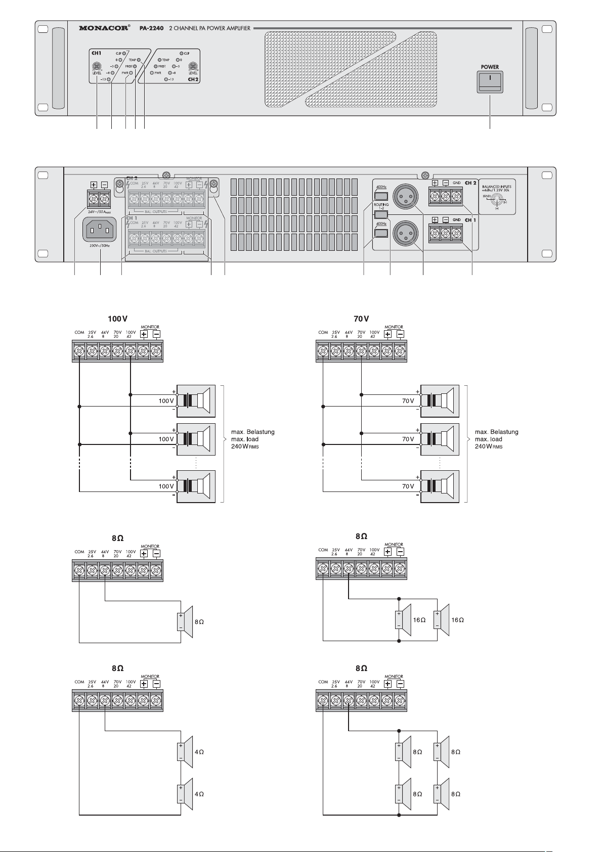
Es können ELA-Lautsprecher (Abb. 3 und 4) oder
8-Ω-Lautsprecher bzw. Lautsprechergruppen mit
einer Gesamtimpedanz von mindestens 8 Ω (Abb.
5 – 8) angeschlossen werden.
4.1.1 ELA- und Monitorlautsprecher
Vorsicht! Bei ELA-Lautsprechern (Abb. 3 und 4)
darf die Gesamtbelastung durch die Lautsprecher nicht mehr als 240 W Sinus pro
Kanal betragen, sonst wird der Verstärker
über lastet und eventuell beschädigt.
100-V-Monitorlautsprecher [an den Klemmen MONITOR (10)] müssen hierbei mit
berücksichtigt werden.
Die Lautsprecher in Gruppen für jede Zone an
die entsprechenden Lautsprecherklemmen (9) an schlie ßen. Dabei auf die richtige Polarität achten
(Plus- und Minusanschlüsse, wie in Abb. 3 und 4 dargestellt). Der Plusanschluss der Lautsprecher kabel
ist immer besonders gekennzeichnet. Für jeden
Kanal lässt sich zu Kontrollzwecken ein 100-V-Moni torlautsprecher an die Klemmen MONITOR (10)
anschließen. Die Klemmen MONITOR sind mit den
Klemmen COM und 100 V/42 Ω parallelgeschaltet.
4.1.2 8-Ω-Lautsprecher bzw. Lautsprechergruppen mit einer Gesamtimpedanz von 8 Ω
Die Abbildungen 5 bis 8 zeigen verschiedene Möglichkeiten eine 8-Ω-Impedanz mit entsprechenden
Lautsprechern zu erreichen. Die Lautsprecher für
jede Zone an die Klemmen COM und 44 V/8 Ω (9)
an schließen. Dabei auf die richtige Polarität achten
(Plus- und Minusanschlüsse, wie in Abb. 5–8 dargestellt). Der Plusanschluss der Lautsprecherkabel
ist immer besonders gekennzeichnet.
4.2 Eingänge
Jeder Kanal kann über die XLR-Buchsen (14) oder
über die Schraubanschlüsse (15) ein separates Eingangssignal erhalten. Ein Eingangssignal lässt sich
aber auch auf beide Kanäle verteilen. Dazu die
Taste ROUTING 1-2 (13) drücken und das Signal
nur auf einen der beiden Eingänge geben.
Zur Vollausteuerung wird ein Signal von +4dBu =
1,2 V benötigt. Die Signalquelle sollte symmetrisch
an den entsprechenden Eingang angeschlossen
werden. Dadurch wird die beste Störunterdrückung
erreicht. Ist der Ausgang der Signalquelle asymmetrisch (z. B. bei Cinch-Buchsen), beim Anschluss
über die XLR-Buchse einen entsprechenden Adapter verwenden (z. B. NA-2MPMF von MONACOR)
oder beim Anschluss über die Schraubanschlüsse
jeweils die Klemme mit der Klemme GND verbinden. Das Signal an und die Masse an GND an schließen.
4.3 Strom- und Notstromversorgung
1) Zum Schluss das beiliegende Netzkabel zuerst in
die Netzbuchse (8) und dann in eine Steckdose
(230 V~/ 50 Hz) stecken.
2) Soll der Verstärker bei einem Netzausfall weiter-
arbeiten, an die Klemmen 24 V (7) eine 24-V-
Notstrom einheit (z. B. PA-24ESP von MONACOR)
an schließen. Bei einer Kabellänge bis zu 4 m ist
WARNUNG Der Verstärker darf nicht ohne die
Schutzabdeckung (11) betrieben werden. Im Betrieb liegen an den Lautsprecheranschlüssen (9, 10) gefähr liche Span nungen bis 100 V an. Nach
dem Anschließen die Ab deckung wieder festschrauben, damit die Kontakte vor Berührung geschützt sind.
Soll das Gerät endgültig aus dem Betrieb
genommen werden, übergeben Sie es zur
umweltgerechten Entsorgung einem örtlichen Recycling betrieb.
G
Never pull the mains cable to disconnect the
mains plug from the mains socket, always seize
the plug.
G
For cleaning only use a dry, soft cloth, by no
means chemicals or water.
G
No guarantee claims for the unit and no liability for
any resulting personal damage or material damage will be accepted if the unit is used for other
purposes than originally intended, if it is not correctly connected, operated, or not repaired in an
expert way.
G
Important for U. K. Customers!
The wires in this mains lead are coloured in ac cord ance with the follow ing code:
green/ yellow = earth
blue = neutral
brown = live
As the colours of the wires in the mains lead of this
appliance may not correspond with the coloured
markings identifying the terminals in your plug,
proceed as follows:
1. The wire which is coloured green and yellow
must be con nected to the terminal in the plug
which is mark ed with the letter E or by the earth
symbol , or coloured green or green and yellow.
2. The wire which is coloured blue must be con nected to the terminal which is marked with the
letter N or coloured black.
3. The wire which is coloured brown must be con nected to the terminal which is marked with the
letter L or coloured red.
Warning – This appliance must be earthed.
3 Placing the Amplifier
The amplifier is designed for insertion into a rack
(482 mm/19″) but it can also be used as a table top
unit. In any case, air must be allowed to pass
through all air vents to ensure a sufficient cooling of
the power amplifiers.
3.1 Rack installation
2 rack spaces (= 89 mm) are required for rack installation. To prevent top-heaviness of the rack, the
amplifier must be inserted into the lower part of the
rack. For a safe fixing the front panel alone is not
sufficient. The amplifier must additionally be screw ed to the rack by means of the rear mounting straps.
The heated air blown out from the amplifier must
be allowed to leave the rack rearwards or upwards.
Otherwise the heat accumulation in the rack may not
only damage the amplifier but other units as well. In
case of insufficient heat dissipation, insert a ventilation unit into the rack above the amplifier.
4 Connecting the Amplifier
All connections should only be made by skilled personnel and by any means with the amplifier
switched off!
4.1 Speakers
The connections for the speak ers are underneath
the protective cover (11). For connection screw off
the cover.
PA speakers (fig. 3 and 4) or 8 Ω speakers or speak er
groups with a total impedance of at least 8 Ω (figs. 5 to
8) can be connected.
4.1.1 PA speakers and monitor speakers
Caution! In case of PA speakers (figs. 3 and 4) the
total load by the speakers must not
exceed 240W
RMS per channel, otherwise
the amplifier may be damaged by overload. 100 V monitor speakers [connected
to the terminals MONITOR (10)] must be
taken into account.
Connect the speakers in groups for each zone to the
corresponding speaker terminals (9). Observe the
correct polarity (positive and negative connections
as shown in figs. 3 and 4). The positive connection
of the speaker cables is always specially marked.
For each channel it is possible to connect a 100 V
monitor speaker to the terminals MONITOR (10) for
monitoring purposes. The terminals MONITOR are
connected in parallel to the terminals COM and
100 V/42 Ω.
4.1.2 8 Ω speakers or speaker groups with a
total impedance of 8 Ω
Figs. 5 to 8 show different possibilities to reach an 8 Ω
impedance with corresponding speakers. Connect
the speakers for each zone to the terminals COM and
44 V/8 Ω (9). Observe the correct polarity (positive
and negative connections as shown in figs. 5 to 8).
The positive connection of the speaker cables is
always specially marked.
4.2 Inputs
Each channel can receive a separate input signal
via the XLR jacks (14) or the screw connections
(15). However, an input signal can also be distri b uted to both channels. For this purpose, press the
button ROUTING 1-2 (13) and feed the signal to one
input only.
WARNING The amplifier must not be operated
without the protective cover (11). During operation there are hazardous
voltages of up to 100 V at the speaker
connections (9, 10). After connect ing,
tightly screw the cover again so that
the contacts are protected against
touching.
If the unit is to be put out of operation de finitively, take it to a local recycling plant for a
disposal which is not harmful to the environment.
5
GB
D
A
CH

ein Kabelquerschnitt von mindestens 5 mm2er forderlich.
Hinweis: Liegt die 24-V-Spannung von der
Notstromeinheit an den Anschlüssen 24V an,
lässt sich der Verstärker mit dem Schalter
POWER (6) nicht ausschalten. Er schaltet bei
einem Netzausfall oder im ausgeschalteten
Zustand automatisch auf die Notstromversorgung um.
5 Bedienung
1) Zunächst die beiden Pegelregler LEVEL (1) in die
Position “0” stellen.
2) Den Verstärker mit der Taste POWER (6) einschalten. Die grünen Betriebsanzeigen PWR (3)
leuchten.
3) Die beiden Pegelregler LEVEL (1) für die beiden
Kanäle (Zonen) auf die ge wünschten Lautstärkewerte einstellen. Jeder Kanal ist mit einer Pegel anzeige (2) ausgestattet. Bei Übersteuerung
leuchtet die entsprechende rote Anzeige CLIP.
Dann die Lautstärke mit dem dazugehörigen
Regler reduzieren.
4) Für eine bessere Sprachverständlichkeit lässt
sich mit der Taste 400 Hz (12) für jeden Kanal
getrennt ein Hochpass (400 Hz, 6 dB/ Okt.) einschalten. Im Zweifelsfall sollte die Taste gedrückt
werden. Tieffrequente Störgeräusche werden so
unterdrückt.
6 Schutzschaltungen
Der Verstärker ist an den Eingängen durch einen
50-Hz-Hochpass gegen Rumpelgeräusche und
durch einen 30-kHz-Tiefpass gegen hochfrequente
Störgeräusche geschützt. Weitere Schaltungen dienen zum Schutz gegen Überlastung und Überhitzung. Bei aktivierter Schutzschaltung leuchtet die
Anzeige PROT (4) und der entsprechende Kanal ist
stummgeschaltet:
1. ca. 1 Sekunde lang nach dem Einschalten (Einschaltverzögerung)
2. wenn der Verstärker überlastet ist
3. wenn der Verstärker überhitzt ist; zusätzlich
leuchtet die Anzeige TEMP (5)
Leuchtet eine der Anzeigen PROT während des
Betriebs auf oder erlischt sie nicht nach dem Einschalten, den Verstärker ausschalten und die Fehlerursache beheben.
7 Technische Daten
Sinusausgangsleistung: . . 2 × 240 W
Klirrfaktor: . . . . . . . . . . . . . < 1 %
Lautsprecherausgänge: . . 100 V, 70 V, 25 V oder
8Ω
Ausgangsimpedanz
100 V: . . . . . . . . . . . . . . . 42 Ω
70 V: . . . . . . . . . . . . . . . 20 Ω
25 V: . . . . . . . . . . . . . . . 2,6 Ω
Eingänge
Empfindlichkeit: . . . . . . . +4 dBu (1,2 V)
Impedanz: . . . . . . . . . . . 30 kΩ
Beschaltung: . . . . . . . . . symmetrisch
Frequenzbereich: . . . . . . . 35 –20000 Hz,
-
3dB
Hochpass: . . . . . . . . . . . . . 400 Hz, 6 dB/ Okt.
(schaltbar)
Signal/ Rauschabstand: . . > 100 dB (A-bewertet)
Einsatztemperatur: . . . . . . 0 – 40 °C
Stromversorgung
Netzspannung: . . . . . . . 230 V~/50 Hz
Leistungsaufnahme: . . . 1300 VA
Notstromversorgung: . . . 24 V
Gleichstromaufnahme: . 55 A
Abmessungen (B×H×T): .482 × 89 × 374mm,
2HE
Gewicht: . . . . . . . . . . . . . . 18 kg
Änderungen vorbehalten.
For optimum level control, a signal of +4 dBu =
1.2 V is required. The signal source should have a
balanced connection to the corresponding input.
Thus, the optimum interference suppression is ob tained. If the output of the signal source is un balanced (e. g. in case of phono jacks), use a corresponding adapter (e. g. NA-2MPMF by MONACOR)
for connection via the XLR jack or connect each ter minal to the terminal GND if the screw connections are used. Connect the signal to and the
ground to GND.
4.3 Power supply and emergency power supply
1) Finally connect the supplied mains cable to
the mains jack (8) first and then to a socket
(230 V~/ 50 Hz).
2) For continuous operation of the amplifier in case
of a possible mains failure, connect a 24 V emergency power supply unit (e. g. PA-24ESP from
MONACOR) to the terminals 24 V (7). With a
cable length of up to 4 m, a cable cross section of
5mm
2
is required as a minimum.
Note: If the 24 V voltage from the emergency
power unit is present at the terminals 24 V , the
amplifier cannot be switched off with the switch
POWER (6). In case of a mains failure or if it is
switched off, it switches automatically to the
emergency power supply.
5 Operation
1) First put the two LEVEL controls (1) to the position “0”.
2) Switch on the amplifier with the button POWER
(6). The green operating LEDs PWR (3) light up.
3) Adjust the two LEVEL controls (1) for the two
channels (zones) to the desired volume values.
Each channel is equipped with level LEDs (2). In
case of overload, the corresponding red LED
CLIP lights up. In this case, reduce the volume
with the corresponding control.
4) To improve the speech intelligibility, a high-pass filter (400 Hz, 6dB/oct.) can be switched on for each
channel separately with the button 400 Hz (12). In
case of doubt, the button should be pressed.
Thus, low frequency interference is suppressed.
6 Protective Circuits
At the inputs, the amplifier is protected against
rumble noise by a 50 Hz high-pass filter and against
high frequency interference by a 30 kHz low-pass filter. Further circuits serve as a protection against
overload and overheating. If the protective circuit is
activated, the LED PROT (4) lights up and the corresponding channel is muted:
1. for approx. 1 second after switching on (switchon delay)
2. in case of overload of the amplifier
3. in case of overheating of the amplifier; the LED
TEMP (5) lights up additionally
If one of the LEDs PROT lights up during operation
or if it does not extinguish after switching on, switch
off the amplifier and eliminate the source of error.
7 Specifications
RMS output power: . . . . . . 2 × 240 W
THD: . . . . . . . . . . . . . . . . . < 1 %
Speaker outputs: . . . . . . . . 100V, 70 V, 25 V, or
8Ω
Output impedance
100 V: . . . . . . . . . . . . . . . 42 Ω
70 V: . . . . . . . . . . . . . . . 20 Ω
25 V: . . . . . . . . . . . . . . . 2.6 Ω
Inputs
Sensitivity: . . . . . . . . . . . +4 dBu (1.2 V)
Impedance: . . . . . . . . . . 30 kΩ
Wiring: . . . . . . . . . . . . . . balanced
Frequency range: . . . . . . . 35 – 20 000 Hz,
-
3dB
High-pass filter: . . . . . . . . . 400 Hz, 6 dB /oct.
(to be switched)
S/ N ratio: . . . . . . . . . . . . . > 100 dB (A weighted)
Ambient temperature: . . . . 0 – 40 °C
Power supply
Mains voltage: . . . . . . . . 230 V~/ 50 Hz
Power consumption: . . . 1300 VA
Emergency power supply: 24 V
DC consumption: . . . . . . 55 A
Dimensions (W × H × D): . 482 × 89 × 374 mm,
2 rack spaces
Weight: . . . . . . . . . . . . . . . 18 kg
Subject to technical modification.
6
GB
D
A
CH
All rights reserved by MONACOR®INTERNATIONAL GmbH & Co. KG. No part of this instruction manual
may be reproduced in any form or by any means for any commercial use.
Diese Bedienungsanleitung ist urheberrechtlich für MONACOR
®
INTERNATIONAL GmbH & Co. KG
geschützt. Eine Reproduktion für eigene kommerzielle Zwecke – auch auszugsweise – ist untersagt.

7

Vous trouverez sur la page 3, dépliable, les éléments et branchements décrits.
1 Eléments et branchements
1.1 Face avant
1 Potentiomètre de réglage de niveau pour les
canaux 1 et 2
2 Affichage de niveau pour les canaux 1 et 2 :
en cas de surcharge la LED rouge CLIP sʼallume.
3 Témoin de fonctionnement PWR pour les ca -
naux 1 et 2
4 LED PROT pour les canaux 1 et 2; sʼallume
lorsque le circuit de protection est activé :
1. pendant 1 seconde environ après la mise
sous tension (temporisation dʼallumage)
2. en cas de surcharge
3. en cas de surchauffe
5 LED TEMP en cas de surchauffe pour les ca -
naux 1 et 2 :
sʼallume lorsque la température du refroidisseur
du canal correspondant atteint 100 °C. En ce
cas, le canal est muet. La LED rouge PROT (4)
sʼallume.
6 Interrupteur POWER Marche/Arrêt
Remarque : Si une tension 24 V dʼune unité dʼalimentation de secours est présente à la borne
24 V (7), lʼamplificateur ne peut pas être éteint.
1.2 Face arrière
7 Bornes à vis pour une alimentation de secours
(24 V )
8 Prise pour le cordon secteur 230 V~/50Hz
9 Bornes haut-parleurs
10 Borne pour un haut-parleur monitor 100 V (par
exemple pour effectuer des contrôles)
Important : Ces bornes sont branchées en pa -
rallèle avec celles pour les haut-parleurs 100 V
(COM et 100 V/42 Ω). Ne surchargez pas lʼamplificateur. Cette charge par un haut-parleur
monitor doit être ajoutée à la charge par les au tres haut-parleurs principaux pour calculer la
charge totale pour un canal.
11 Cache de protection pour les connexions haut-
parleurs
12 Interrupteur Marche/Arrêt 400Hz pour les filtres
passe-haut des canaux 1 et 2 (diminue les
basses)
13 Interrupteur ROUTING 1-2 : partage dʼun signal
dʼentrée sur les deux canaux
14 Entrées par prises XLR symétriques : sensibilité
pour réglage optimal +4 dBu (1,2 V)
15 Entrées symétriques par bornes à vis : sensibilité
pour réglage optimal +4 dBu (1,2 V)
2 Conseils de sécurité et dʼutilisation
Lʼappareil répond à toutes les directives nécessaires de lʼUnion Européenne et porte donc le symbole .
Respectez scrupuleusement les points suivants :
G
Lʼappareil nʼest conçu que pour une utilisation en
intérieur. Protégez-le des éclaboussures, de tout
type de projections dʼeau, dʼune humidité dʼair élevée et de la chaleur (température ambiante
admissible 0 – 40 °C).
G
En aucun cas, vous ne devez pas poser dʼobjet
contenant du liquide ou un verre sur lʼappareil.
G
La chaleur dégagée par lʼappareil doit être évacuée par une circulation dʼair correcte. Nʼobstruez
pas les ouïes de ventilation.
G
Ne faites pas fonctionner lʼappareil et débranchez
le cordon secteur immédiatement dans les cas
suivants :
1. lʼappareil ou le cordon secteur présentent des
dommages visibles.
2. après une chute ou accident similaire, vous
avez un doute sur lʼétat de lʼappareil.
3. des dysfonctionnements apparaissent.
Dans tous les cas, les dommages doivent être
réparés par un technicien spécialisé.
AVERTISSEMENT Lʼappareil est alimenté par une
tension dangereuse en 230 V~.
Ne touchez jamais lʼintérieur
de lʼappareil et ne faites rien
tomber dans les ouïes de ventilation car, en cas de mauvaise
manipulation, vous pouvez su bir une décharge électrique.
Pendant le fonctionnement, une tension dangereuse jusquʼà 100 V est présente aux bornes hautparleurs (9, 10). Ne faites jamais fonctionner lʼamplificateur sans le couvercle de protection (11).
Les branchements ne doivent être effectués ou
modifiés que si lʼamplificateur est éteint.
AVERTISSEMENT Ne faites jamais fonction -
ner lʼamplificateur sans le
cache. Sinon, il y a danger
de décharge électrique en
cas de contact avec les
branchements.
A pagina 3, se aperta completamente, vedrete
sempre gli elementi di comando e i collegamenti
descritti.
1 Elementi di comando e collegamenti
1.1 Pannello frontale
1 Regolatori livelli per i canali 1 e 2
2 Indicazione livello per i canali 1 e 2;
nel caso di sovrapilotaggio si accende la spia
rossa CLIP
3 Spia di funzionamento PWR per i canali 1 e 2
4 Spia PROT per i canali 1 e 2;
si accende se il circuito di protezione è stato attivato:
1. per ca. 1 secondo dopo lʼaccensione (ritardo
dellʼaccensione)
2. se lʼamplificatore è sovraccaricato
3. se lʼamplificatore è surriscaldato
5 Spia di surriscaldamento TEMP per i canali 1 e 2;
si accende, quando la temperatura del dissipatore di calore del relativo canale ha raggiunto
100 °C. In questo caso, il canale viene disattivato. In più si accende la spia rossa PROT (4)
6 Interruttore on/off POWER
N. B.: Se al contatto 24 V (7) è presente una
tensione di 24 V proveniente da un gruppo
di continuità, lʼamplificatore non può essere
spento.
1.2 Retro
7 Contatti a vite per un gruppo di continuità (24 V )
8 Presa per il cavo rete in dotazione per il collega-
mento a 230 V~/50 Hz
9 Contatti per gli altoparlanti
10 Contatto per altoparlante monitor con tecnica
100 V per controllo.
Importante! Questi morsetti sono collegati in
parallelo con i morsetti per altoparlanti con tecnica 100 V (COM e 100V/42 Ω). Non sovraccaricare lʼamplificatore. La potenza dellʼaltoparlante
monitor va aggiunta alla potenza degli altri altoparlanti per poter calcolare la potenza globale
per un canale.
11 Copertura protettiva per i contatti per altoparlanti
12 Interruttore on/off 400 Hz per i passaalti dei
canali 1 e 2 (abbassa i bassi)
13 Interruttore ROUTING 1-2 per distribuire un se -
gnale dʼingresso su due canali
14 Ingressi segnale mediante prese XLR simmetri-
che; sensibilità per pilotaggio completo +4 dBu
(1,2 V)
15 Ingressi segnale simmetrici per contatti a vite;
sensibilità per pilotaggio completo +4 dBu (1,2V)
2 Avvertenze di sicurezza
Lʼapparecchio è conforme a tutte le direttive richieste dellʼUE e pertanto porta la sigla .
Si devono osservare assolutamente anche i
seguenti punti:
G
Lʼapparecchio è adatto solo per lʼuso allʼinterno di
locali. Proteggerlo dallʼacqua gocciolante e dagli
spruzzi dʼacqua, da alta umidità dellʼaria e dal
calore (temperatura dʼimpiego ammessa fra 0 °C
e 40 °C).
G
Non depositare sullʼapparecchio dei contenitori
riempiti di liquidi, p. es. bicchieri.
G
Devʼessere garantita la libera circolazione dellʼaria per dissipare il calore che viene prodotto allʼinterno dellʼapparecchio. Non coprire in nessun
modo le fessure dʼaerazione.
G
Non mettere in funzione lʼapparecchio e staccare
subito la spina rete se:
1. lʼapparecchio o il cavo rete presentano dei
danni visibili;
2. dopo una caduta o dopo eventi simili sussiste il
sospetto di un difetto;
3. lʼapparecchio non funziona correttamente.
Per la riparazione rivolgersi sempre ad unʼofficina
competente.
AVVERTIMENTO Lʼapparecchio funziona con
pericolosa tensione di rete
(230 V~). Non intervenire mai
al suo interno e non inserire
niente nelle fessure di aerazione! Esiste il pericolo di una
scarica elettrica.
Durante il funzionamento, ai contatti per altoparlanti (9, 10) è presente una tensione fino a 100 V,
pericolosa in caso di contatto. Non usare lʼamplificatore senza la copertura protettiva (11).
Eseguire o modificare tutti i collegamento solo con
lʼimpianto PA spento.
AVVERTIMENTO Non usare mai lʼamplifica-
tore senza la copertura.
Altrimenti il contatto può
provocare una scossa elet trica.
8
I
F
B
CH

G
Ne débranchez jamais lʼappareil en tirant sur le
cordon secteur ; retirez toujours le cordon secteur
en tirant la fiche.
G
Pour le nettoyage, utilisez un chiffon sec et doux,
en aucun cas de produits chimiques ou dʼeau.
G
Nous déclinons toute responsabilité en cas de
dommages corporels ou matériels résultants si lʼappareil est utilisé dans un but autre que celui pour
lequel il a été conçu, sʼil nʼest pas correctement
branché, utilisé ou réparé par une personne habilitée ; en outre, la garantie deviendrait caduque.
3 Possibilités dʼutilisation
Lʼamplificateur est prévu pour une installation en
rack (482 mm/19″) mais peut également être posé
directement sur une table. Dans tous les cas, veillez
à assurer une circulation dʼair via les orifices de ventilation pour assurer un refroidissement suffisant de
lʼamplificateur.
3.1 Installation en rack
Pour un montage en rack 2 unités (= 89 mm) sont
nécessaires. Pour éviter toute chute, lʼamplificateur
doit être placé dans la partie inférieure du rack ; pour
une fixation sûre, le panneau avant ne suffit pas ;
lʼamplificateur doit être vissé à lʼaide de fixations
également à lʼarrière.
Lʼair chaud dégagé par lʼamplificateur doit être
évacué vers lʼarrière ou le haut, sinon, il y a une
accumulation de chaleur dans le rack : lʼamplificateur et les autres appareils seraient endommagés :
si la dissipation de chaleur dans le rack nʼest pas
suffisante, insérez un ventilateur dans le rack audessus de lʼamplificateur.
4 Connexions
Seul un technicien habilité peut effectuer les branchements, lʼamplificateur doit être impérativement
débranché en ce cas !
4.1 Haut-parleurs
Les branchements pour les haut-parleurs se trouvent sous le couvercle de protection (11). Dévissezle pour effecteur les branchements.
Il est possible de brancher des haut-parleurs Public
Address (schémas 3 et 4) ou des haut-parleurs 8 Ω
ou des groupes de haut-parleurs avec une impé dance totale de 8 Ω au moins (schémas 5–8).
4.1.1 Haut-parleurs monitor ou Public Address
Attention ! Pour des haut-parleurs Public Address
(schémas 3 –4), la charge totale ne doit
pas dépasser 240 Wrms par canal
sinon, lʼamplificateur est en surcharge
et peut être endommagé. Des haut-parleurs monitor 100 V [aux bornes MONITOR (10)], doivent être pris en compte.
Reliez les haut-parleurs en groupe pour chaque
zone aux bornes correspondantes (9) : veillez à respecter la polarité (plus et moins, schémas 3 – 4). Le
branchement Plus des câbles haut-parleurs est toujours repéré. Pour chaque canal, il est possible de
brancher un haut-parleur monitor 100 V aux bornes
MONITOR (10) pour effectuer des contrôles. Les
bornes MONITOR sont branchées en parallèle aux
bornes COM et 100 V/ 42 Ω.
4.1.2 Haut-parleurs 8 Ω ou groupes de haut-parleurs avec une impédance totale de 8 Ω
Les schémas 5 à 8 montrent les différentes possibilités pour atteindre une impédance de 8 Ω avec les
haut-parleurs correspondants. Reliez les haut-parleurs pour chaque zone aux bornes COM et
44 V/ 8 Ω (9) ; veillez à respecter la polarité (plus et
moins, schémas 5 – 8), le branchement Plus des
câbles haut-parleurs est toujours repéré.
4.2 Entrées
Chaque canal peut recevoir via les prises XLR (14)
ou les bornes à vis (15) un signal dʼentrée distinct.
Un signal dʼentrée peut être réparti sur deux canaux :
enfoncez la touche ROUTING 1-2 (13), appliquez le
signal à une des deux entrées.
Pour un réglage optimal, un signal de +4 dBu =
1,2 V est nécessaire. La source doit être branchée
en symétrique à lʼentrée correspondante. Ainsi la
meilleure suppression des interférences est obte nue. Si la sortie de la source est asymétrique (par
exemple par prises XLR), utilisez en cas de branchement via la prise XLR un adaptateur (par exemple
NA-2MPMF de MONACOR) ou reliez la borne à
la borne GND en cas de connexion via les bornes à
vis. Reliez le signal au et la masse à GND.
4.3 Alimentation et alimentation de secours
1) Reliez maintenant le cordon secteur livré à la
prise (8) puis lʼautre extrémité à une prise secteur 230 V~/ 50 Hz.
2) Si lʼamplificateur doit continuer à travailler en cas
de coupure de courant, reliez aux bornes 24 V
(7) une alimentation de se cours 24 V (p. ex. PA24ESP de MONACOR). Pour une longueur de
câble jusquʼà 4 m, la section minimale nécessaire du câble est de 5 mm
2
.
AVERTISSEMENT Lʼamplificateur ne doit pas
fonctionner sans le couvercle
de protection (11). Pendant le
fonc tionnement, des tensions
dangereuses, jusquʼà 100 V,
sont présentes aux con nexions haut-parleurs (9, 10).
Une fois les branchements
effectués, revissez solidement
le couvercle afin de protéger
les connexions de tout contact.
Lorsque lʼappareil est définitivement retiré
du service, vous devez le déposer dans
une usine de recyclage de proximité pour
contribuer à son élimination non polluante.
G
Staccare il cavo rete afferrando la spina, senza ti rare il cavo.
G
Per la pulizia usare solo un panno morbido,
asciut to; non impiegare in nessun caso acqua o
prodotti chimici.
G
Nel caso dʼuso improprio, di collegamenti sba gliati, dʼimpiego scorretto o di riparazione non a
regola dʼarte dellʼapparecchio, non si assume
nessuna responsabilità per eventuali danni consequenziali a persone o a cose e non si assume
nessuna garanzia per lʼapparecchio.
3 Possibilità di collocamento
Lʼamplificatore è previsto per il montaggio in un rack
(482 mm/19″), ma può essere collocato anche su
un tavolo. In ogni caso devʼessere possibile che lʼaria circoli liberamente attraverso tutte le fessure di
aerazione per garantire un raffreddamento sufficiente dellʼamplificatore.
3.1 Montaggio in un rack
Per il montaggio in un rack occorrono due unità di
altezza (= 89 mm). Conviene sistemare lʼamplificatore nella parte inferiore del rack per non compromettere lʼequilibrio. Il pannello frontale non basta per
il fissaggio. Lʼamplificatore devʼessere fissato a vite
con il rack servendosi delle apposite linguette sul
retro.
Lʼaria espulsa dallʼamplificatore deve poter
uscire di dietro e in alto. Altrimenti lʼamplificatore si
può ri scaldare troppo con possibili danni anche alle
altre apparecchiature. Se il deflusso dellʼaria calda
non è garantito, conviene installare un ventilatore
sopra lʼamplificatore.
4 Collegare lʼamplificatore
Tutti i collegamenti dovrebbero essere eseguiti solo
da un esperto qualificato e con lʼapparecchio assolutamente spento!
4.1 Altoparlanti
I contatti per gli altoparlanti si trovano sotto la copertura protettiva (11). Per eseguire i collegamenti svitare la copertura.
Si possono collegare altoparlanti PA (figg. 3 e 4)
oppure (gruppi di) altoparlanti a 8 Ω con impedenza
globale non inferiore a 8 Ω (figg. 5 – 8).
4.1.1 Altoparlanti PA e monitor
Attenzione! Negli altoparlanti PA (figg. 3 e 4), la
potenza globale non deve superare
rispettivamente i 240 W
RMS per ogni
canale per non sovraccaricare ed
eventualmente danneggiare lʼamplificatore. Bisogna prendere in considerazione anche gli altoparlanti monitor
con tecnica 100 V [ai morsetti MONITOR (10)].
Collegare gli altoparlanti con gli appositi morsetti (9)
a gruppi per ogni settore, rispettando la corretta
polarità (positivo e negativo come illustrato in figg. 3
e 4). Il positivo dei cavi è sempre quello contrasse gnato. A scopo di controllo è possibile collegare per
ogni canale ai morsetti MONITOR (10) un altoparlante monitor con tecnica 100 V. I morsetti MONI-
TOR sono collegati in parallelo con i morsetti COM e
100 V/42 Ω.
4.1.2 Altoparlanti a 8 Ω o gruppi di altoparlanti
con impedenza globale di 8 Ω
Le figg. 5– 8 mostrano diverse possibilità per rag giungere unʼimpedenza di 8 Ω con i vari altoparlanti.
Collegare gli altoparlanti per ogni settore con morsetti COM e 44 V/8 Ω (9), rispettando la corretta
polarità (positivo e negativo come illustrato in figg.
5 –8). Il positivo dei cavi è sempre quello contrassegnato.
4.2 Ingressi
Attraverso le prese XLR (14) o i contatti a vite (15),
ogni canale può avere un proprio segnale dʼingresso. Tuttavia, uno stesso segnale dʼingresso può
essere distribuito fra i due canali. Per fare ciò premere il tasto ROUTING 1-2 (13) e immettere il se gnale su un solo canale.
Per il pilotaggio totale è richiesto un segnale di
+4 dBu = 1,2 V. La sorgente del segnale dovrebbe
avere un collegamento simmetrico con il relativo
ingresso. In questo modo si raggiunge la migliore
soppressione dei disturbi. Se lʼuscita della sorgente
è asimmetrica (p. es. con prese cinch) occorre usare
un adattatore se si usano le prese XLR (p. es. NA2MPMF della MONACOR), oppure, usando i contatti a vite, occorre collegare il morsetto con il
morsetto GND. Collegare il segnale con e la
massa con GND.
4.3 Alimentazione normale e di emergenza
1) Alla fine inserire il cavo rete in dotazione prima
nella presa (8) e quindi nella presa di rete
(230 V~/ 50 Hz).
2) Se lʼamplificatore deve funzionare anche in caso
di caduta di rete, collegare un gruppo di continuità di 24 V (p. es. PA-24ESP di MONACOR)
AVVERTIMENTO Lʼapparecchio non deve essere
usato senza la copertura protettiva (11). Durante il funzionamento, ai contatti per altoparlanti (9, 10) sono presenti
tensioni pericolose fino a 100 V.
Dopo aver eseguito i collegamento riavvitare la copertura
per proteggere i collegamenti
dal contatto accidentale.
Se si desidera eliminare lʼapparecchio definitivamente, consegnarlo per lo smaltimento ad unʼistituzione locale per il rici claggio.
9
I
F
B
CH

Remarque : si une tension 24 V de lʼunité
dʼalimentation de secours est présente aux
bornes 24 V , lʼamplificateur ne peut pas être
éteint avec lʼinterrupteur POWER (6). Il commute
en cas de coupure de courant ou sʼil est éteint,
automatiquement sur lʼalimentation de secours.
5 Fonctionnement
1) Mettez les deux réglages LEVEL (1) sur la position “0”.
2) Allumez lʼamplificateur avec la touche POWER
(6), les LEDs vertes, témoins de fonctionnement
PWR (3) sʼallument.
3) Réglez les deux potentiomètres LEVEL (1) pour
les deux canaux (zones) sur le volume souhaité.
Chaque canal est doté dʼun affichage de niveau
(2). En cas de surcharge, la LED rouge CLIP correspondante brille. Réduisez le volume avec le
potentiomètre correspondant.
4) Pour une meilleure compréhension de la voix, il
est possible de brancher un passe-haut (400 Hz,
6 dB/ oct.), séparément pour chaque canal avec
la touche 400 Hz (12). En cas de doute, la touche
devrait être enfoncée. Ainsi, les interférences
dans les fréquences graves seront supprimées.
6 Circuits de protection
Lʼamplificateur est protégé aux entrées par un filtre
passe-haut 50 Hz contre les ronflements et par un
filtre passe-bas 30 kHz contre les interférences
hautes fréquences. Dʼautres circuits de protection
sont prévus contre les surcharges et surchauffes.
Lorsquʼun circuit de protection est activé, la LED
PROT (4) du canal correspondant brille, le canal est
muet :
1. pendant 1 seconde environ après la mise sous
tension (temporisation dʼallumage)
2. en cas de surcharge
3. en cas de surchauffe; la LED TEMP (5) sʼallume.
Si un des LEDs PROT sʼallume pendant le fonctionnement ou ne sʼéteint pas après lʼallumage, éteignez lʼamplificateur et résolvez le problème.
7 Caractéristiques techniques
Puissance de sortie RMS : 2 × 240 W
Taux de distorsion : . . . . . . < 1 %
Sorties haut-parleurs : . . . . 100 V, 70 V, 25 V ou
8Ω
Impédance de sortie
100 V : . . . . . . . . . . . . . . 42 Ω
70 V : . . . . . . . . . . . . . . 20 Ω
25 V : . . . . . . . . . . . . . . 2,6 Ω
Entrées
Sensibilité : . . . . . . . . . . +4 dBu (1,2V)
Impédance : . . . . . . . . . . 30 kΩ
Câblage : . . . . . . . . . . . . symétrique
Bande passante : . . . . . . . 35 –20 000Hz,
-
3dB
Passe-haut : . . . . . . . . . . . 400 Hz, 6 dB/oct.
(commutable)
Rapport signal/ bruit : . . . . > 100 dB (la évalué)
Température dʼutilisation : . 0 –40°C
Alimentation
Alimentation secteur : . . 230 V~/50Hz
Consommation : . . . . . . 1300 VA
Alimentation de secours : 24 V
Consommation DC : . . . 55 A
Dimensions (L × H × P) : . . 482 × 89 × 374 mm,
2U
Poids : . . . . . . . . . . . . . . . . 18 kg
Tout droit de modification réservé.
ai morsetti 24 V (7). Per un cavo fino a 4m di lunghezza è richiesta una sezione di 5 mm2min.
N. B.: Se ai contatti 24 V è presente la tensione di 24 V proveniente dal gruppo di continuità, lʼamplificatore non può essere spento con
lʼinterruttore POWER (6). In caso di caduta di
rete e se è spento, lʼamplificatore pas sa automaticamente allʼalimentazione dʼemer gen za.
5 Funzionamento
1) Per prima cosa posizionare i quattro regolatori di
livello LEVEL (1) sullo “0”.
2) Accendere lʼamplificatore con il tasto POWER
(6). Si accendono le spie verdi di funzionamento
PWR (3).
3) Impostare i regolatori dei livelli (1) per i due canali
(settori) secondo le proprie necessità. Ogni ca nale è equipaggiato con una visualizzazione del
livello (2). In caso di sovrapilotaggio si accende la
spia CLIP. In questo caso ridurre il volume con il
relativo regolatore.
4) Per migliorare la comprensione della lingua parlata, con il tasto 400 Hz (12) si può inserire per
ogni canale un filtro passaalto (400 Hz, 6dB/oct.).
Nel dubbio, conviene premere il tasto. I rumori a
bassa frequenza vengono così soppressi.
6 Circuiti di protezione
Lʼamplificatore è protetto agli ingressi contro i rumori
di passi e simili per mezzo di un passaalto di 50 Hz
e contro i rumori ad alta frequenza con un passabasso di 30 kHz. Altri circuiti sono contro i sovraccarichi e il surriscaldamento. Se un circuito di protezione viene attivato, si accende la spia PROT (4), e
il relativo canale viene disattivato:
1. per 1 secondo ca. dopo lʼaccensione (ritardo dellʼaccensione)
2. se lʼamplificatore è sovraccaricato
3. se lʼamplificatore è surriscaldato si accende inoltre la spia TEMP (5).
Se una delle spie PROT si accende durante il funzionamento o se non si spegne subito dopo lʼaccensione, spegnere lʼamplificatore ed eliminare la
causa del guasto.
7 Dati tecnici
Potenza dʼuscita RMS: . . . 2 × 240 W
Fattore di distorsione: . . . . < 1 %
Uscite altoparlanti: . . . . . . 100 V, 70 V, 25 V o 8 Ω
Impedenza dʼuscita
100 V: . . . . . . . . . . . . . . . 42 Ω
70 V: . . . . . . . . . . . . . . . 20 Ω
25 V: . . . . . . . . . . . . . . . 2,6 Ω
Ingressi
Sensibilità: . . . . . . . . . . . +4 dBu (1,2V)
Impedenza: . . . . . . . . . . 30 kΩ
Contatti: . . . . . . . . . . . . . simmetrici
Banda passante: . . . . . . . . 35 – 20 000 Hz,
-
3dB
Passaalto: . . . . . . . . . . . . . 400 Hz, 6dB/oct.
(commutabile)
Rapporto S/R: . . . . . . . . . . > 100 dB (valutato A)
Temperatura dʼimpiego: . . 0 –40°C
Alimentazione
da rete: . . . . . . . . . . . . . 230 V~/50Hz
Assorbimento potenza: . 1300VA
di emergenza: . . . . . . . . 24 V
Assorbimento cc: . . . . . . 55 A
Dimensioni (L × H × P): . . . 482 × 89 × 374 mm,
2 unità di altezza
Peso: . . . . . . . . . . . . . . . . . 18 kg
Con riserva di modifiche tecniche.
10
I
F
B
CH
Notice dʼutilisation protégée par le copyright de MONACOR®INTERNATIONAL GmbH & Co. KG. Toute
reproduction même partielle à des fins commerciales est interdite.
La MONACOR®INTERNATIONAL GmbH & Co. KG si riserva ogni diritto di elaborazione in qualsiasi forma
delle presenti istruzioni per lʼuso. La riproduzione – anche parziale – per propri scopi commerciali è vietata.

11

Op de uitklapbare pagina 3 vindt u een overzicht
van de bedieningselementen en de aansluitingen.
1 Bedieningselementen en
aansluitingen
1.1 Frontpaneel
1 Niveauregelaar voor beide kanalen 1 en 2
2 VU-LEDʼs voor beide kanalen 1 en 2;
bij oversturing licht de rode LED CLIP op
3 POWER-LED PWR voor beide kanalen 1 en 2
4 LED PROT voor beide kanalen 1 en 2; licht op bij
geactiveerd beveiligingscircuit:
1. gedurende ca. 1 seconde na het inschakelen
(soft start)
2. bij overbelasting van de versterker
3. bij oververhitting van de versterker
5 Oververhittings-LED TEMP voor beide kanalen
1 en 2;
licht op wanneer de koelplaattemperatuur van
het overeenkomstige kanaal 100 °C bereikt. Op
dat moment wordt het kanaal gedempt. Bovendien licht de rode LED PROT (4) op.
6 POWER-schakelaar
Opmerking: Als er door de noodstroomeenheid
een spanning van 24 V naar de aansluiting
24 V (7) wordt gestuurd, kunt u de versterker
niet uitschakelen.
1.2 Achterzijde van het toestel
7 Schroefaansluitingen voor een noodstroomvoe-
ding (24 V )
8 Jack voor aansluiting van het meegeleverde net-
snoer op 230 V~/ 50 Hz
9 Luidsprekeraansluitingen
10 Aansluitingen voor monitorluidsprekers van 100 V
ter controle
Belangrijk! Deze klemmen zijn parallelgescha-
keld met de klemmen voor luidsprekers van
100 V (COM en 100 V/42 Ω). Zorg ervoor dat u
de versterker niet overbelast. De belasting van
een monitorluidspreker moet opgeteld worden bij
de belasting van de overige hoofdluidsprekers,
zodat u de totale belasting voor een kanaal kunt
berekenen.
11 Beschermkap voor de luidsprekeraansluitingen
12 Aan/Uit-schakelaar 400 Hz voor de hoogdoor-
laatfilters van de kanalen 1 en 2 (dempt de basklanken)
13 Schakelaar ROUTING 1-2 om een ingangssig-
naal naar beide kanalen te sturen
14 Signaalingangen via gebalanceerde XLR-jacks;
de gevoeligheid voor volledige uitsturing be draagt +4 dBu (1,2 V)
15 Gebalanceerde signaalingangen via schroef aan -
sluitingen; de gevoeligheid voor volledige uit sturing bedraagt +4 dBu (1,2 V)
2 Veiligheidsvoorschriften
Het apparaat is in overeenstemming met alle verei ste EU-Richtlijnen en is daarom gekenmerkt met .
Let eveneens op het volgende:
G
Het apparaat is enkel geschikt voor gebruik binnenshuis. Vermijd druip- en spatwater, uitzonderlijk warme plaatsen en plaatsen met een hoge
vochtigheid (toegestaan omgevingstemperatuurbereik: 0 – 40 °C).
G
Plaats geen bekers met vloeistof zoals drinkglazen etc. op het apparaat.
G
De warmte die in het toestel ontstaat, moet door
ventilatie worden afgevoerd. Dek de ventilatieopeningen niet af.
G
Schakel het apparaat niet in resp. trek onmiddellijk de stekker uit het stopcontact:
1. wanneer het apparaat of het netsnoer zichtbaar
beschadigd is,
2. wanneer er een defect zou kunnen optreden
nadat het apparaat bijvoorbeeld is gevallen,
3. wanneer het apparaat slecht functioneert.
Het apparaat moet in elk geval hersteld worden
door een gekwalificeerd vakman.
G
Trek de stekker nooit met het snoer uit het stopcontact, maar steeds met de stekker zelf.
WAARSCHUWING De netspanning (230V~) van
het apparaat is levensgevaarlijk. Open het apparaat niet, en
zorg dat u niets in de ventilatieopeningen steekt! U loopt
het risico van een elektrische
schok.
Tijdens het gebruik staan de luidsprekeraansluitingen (9, 10) onder een levensgevaarlijke spanning
tot 100 V. Gebruik de versterker nooit zonder de
beschermkap (11).
De in- en uitgangen mogen enkel aangesloten en
gewijzigd worden, wanneer de geluidsinstallatie is
uitgeschakeld.
WAARSCHUWING Gebruik de versterker nooit
zonder de beschermkap.
Anders loopt bij aanraken
van de aansluitingen het
risico van een elektrische
schok.
Puede encontrar todos los elementos de funcionamiento y las conexiones que se describen en
la página 3 desplegable.
1 Elementos y conexiones
1.1 Panel delantero
1 Potenciómetro de ajuste de nivel para cada de
los canales 1 y 2
2 Visualización de nivel para cada de los canales 1
y 2; en caso de sobrecarga el LED rojo CLIP se
enciende.
3 Testigo de funcionamiento PWR para cada de
los canales 1 y 2
4 LED PROT para cada de los canales 1 y 2; se
enciende cuando el circuito de protección está
activado:
1. durante 1 segundo apróx. después de la
puesta en tensión (temporización de puesta
en tensión)
2. en caso de sobrecarga del amplificador
3. en caso de sobrecalentamiento del amplificador
5 LED TEMP en caso de sobrecalentamiento para
los canales 1 y 2:
se enciende cuando la temperatura del disipador
térmico del canal correspondiente llega a 100 °C.
En este caso el canal se queda mudo. Adicionalmente el LED rojo PROT (4) se enciende.
6 Interruptor POWER ON/OFF
Nota: Si los terminales 24 V (7) reciben un
voltaje de 24 V de un alimentador de socorro,
el amplificador no se puede parar.
1.2 Panel trasero
7 Bornes con tornillos para una alimentación de
emergencia (24 V )
8 Toma para el cable de red entegrado para la
conexión a 230 V~/50 Hz
9 Bornes altavoces
10 Bornes para un altavoz monitor 100 V (p.ej. para
efectuar controles)
¡Importante! Estas bornes están conectadas en
paralelo con las bornes de los altavoces 100 V
(COM y 100 V/42 Ω). No sobrecargar el amplificador. Esta carga por un altavoz monitor tiene
que estar sumado a la carga de los otros altavoces principales para calcular la carga total para
un canal.
11 Tapa protectora para las conexiones de altavoz
12 Interruptor ON/OFF 400 Hz para los filtros pasa-
alto de los canales 1 y 2 (disminuye los bajos)
13 Interruptor ROUTING 1-2: reparte de una señal
de entrada sobre los canales
14 Entradas por tomas XLR simétricas: sensibilidad
para mandar el nivel al óptimo +4 dBu (1,2 V)
15 Entradas simétricas por bornes con tornillos;
sensibilidad para mandar el nivel al óptimo
+4 dBu (1,2 V)
2 Notas de seguridad
Esta unidad cumple con todas las normativas que
requiere la UE y es por ello está marcada con .
Es esencial que tenga en cuenta los puntos si guientes:
G
La unidad sólo está indicada para su uso en interior. Protéjala contra proyecciones y salpicaduras
de agua, una alta humedad del aire y del calor
(temperatura de ambiente admisible 0 – 40 °C).
G
No coloque ningún recipiente con líquido encima
de la unidad, por ejemplo vasos de bebida.
G
El calor generado dentro de la unidad debe evacuarse mediante circulación del aire. Por lo tanto
no deben cubrirse las rejillas de ventilación.
G
No haga funcionar la unidad y desconecte inmediatamente el enchufe de la toma de red:
1. en caso de daños visibles en la unidad o en el
cable de red,
2. si después de una caída o un accidente similar
pudiera haberse producido un defecto,
3. si se producen fallos.
En cualquier caso la unidad debe ser reparada
por personal experto.
ADVERTENCIA La unidad se alimenta con una
tensión de red peligrosa (230 V~).
¡Deje su mantenimiento sólo en
manos de personal especializado
y no inserte nada a través de las
aberturas de ventilación! Una
mani pulación inexperta o la mo dificación de la unidad pueden causar un peligro de descarga eléctrica.
Durante el funcionamiento existe un peligro de
contacto en las conexiones de altavoz (9, 10) con
un voltaje de hasta 100 V. No use nunca el amplificador sin tapa protectora (11).
Haga o cambie todas las conexiones sólo con el
sistema de megafonía apagado.
ADVERTENCIA No use nunca el amplificador
sin la tapa. De otro modo,
cuando toque las conexiones,
existe el riesgo de una descarga eléctrica.
12
E
NL
B

G
Verwijder het stof met een droge, zachte doek.
Gebruik zeker geen water of chemicaliën.
G
In geval van ongeoorloofd of verkeerd gebruik,
verkeerde aansluiting, foutieve bediening of van
herstelling door een niet-gekwalificeerd persoon
vervalt de garantie en de verantwoordelijkheid
voor hieruit resulterende materiële of lichamelijke
schade.
3 Installatie
De versterker is voorzien voor montage in een rack
(482 mm/19″), maar kan ook als tafelmodel gebruikt
worden. In elk geval moet de lucht door alle ventilatieopeningen kunnen stromen, om voldoende ventilatie van de versterker te verzekeren.
3.1 De montage in een rack
Voor de montage in een rack hebt u 2HE (2 rackeenheden = 89 mm) nodig. Om te voorkomen dat
het rack topzwaar wordt, dient de versterker in het
onderste gedeelte van het rack gemonteerd te worden. De frontplaat alleen is niet voldoende voor een
veilige bevestiging. Bovendien moet de versterker
via de montagestrips aan de achterzijde met het
rack vastgeschroefd worden.
De hete lucht die uit de versterker geblazen
wordt, moet achterlangs of bovenlangs uit het rack
afgevoerd kunnen worden. Anders hoopt de warmte
zich op in het rack, waardoor niet enkel de versterker maar ook andere toestellen beschadigd kunnen
worden. Bij onvoldoende warmteafvoer moet u in
het rack een ventilator plaatsen boven de versterker.
4 De versterker aansluiten
De in- en uitgangen mogen enkel door een gekwalificeerde vakman uitgevoerd worden en in elk geval
wanneer de versterker uitgeschakeld is!
4.1 De luidsprekers
De aansluitingen voor de luidsprekers bevinden zich
onder de beschermkap (11). Om de aansluitingen
tot stand te brengen, schroeft u de kap los.
U kunt 100 V-luidsprekers (figuur 3 en 4) of luid sprekers van 8 Ω resp. luidsprekergroepen met een
totale impedantie van minstens 8 Ω (figuur 5 – 8)
aansluiten.
4.1.1 100 V- en monitorluidsprekers
Opgelet! Bij 100 V-luidsprekers (figuur 3 en 4) mag
de totale belasting van de luidsprekers
niet meer dan 240 W
RMS per kanaal be -
dragen. Anders wordt de versterker over belast en eventueel beschadigd. Houd
hierbij ook rekening met de monitorluidsprekers van 100 V [op de klemmen
MONITOR (10)].
Sluit voor elke zone de luidsprekers in groepen aan
op de betreffende luidsprekerklemmen (9). Let daarbij op de juiste polariteit (positieve en negatieve aansluitingen zoals weergegeven in figuren 3 en 4). De
positieve aansluiting van de luidsprekerkabel is
altijd speciaal gemarkeerd. Ter controle kunt u voor
elk kanaal een monitorluidspreker van 100 V aan -
sluiten op de klemmen MONITOR (10). De klemmen
MONITOR zijn parallelgeschakeld met de klemmen
COM en 100 V/42 Ω.
4.1.2 Luidsprekers van 8 Ω resp. luidsprekergroepen met een totale impedantie van 8 Ω
De figuren 5 tot 8 tonen verschillende mogelijkheden om met betreffende luidsprekers een impedantie van 8 Ω te realiseren. Sluit de luidsprekers voor
elke zone aan op de klemmen COM en 44 V/8 Ω (9).
Let daarbij op de juiste polariteit (positieve en negatieve aansluitingen zoals weergegeven in figuren
5 – 8). De positieve aansluiting van de luidsprekerkabel is altijd speciaal gemarkeerd.
4.2 Ingangen
Elk kanaal kan via de XLR-jacks (14) of via de
schroefaansluitingen (15) een afzonderlijk ingangssignaal ontvangen. Een ingangssignaal kan echter
ook over beide kanalen verdeeld worden. Druk hiervoor op de toets ROUTING 1-2 (13), en stuur het
signaal slechts naar een van beide ingangen.
Voor een volledige uitsturing is een signaal van
+4 dBu = 1,2V nodig. De signaalbron moet gebalanceerd aangesloten worden op de overeenkomstige
ingang. Hierdoor worden storingen optimaal onderdrukt. Indien de uitgang van de signaalbron ongebalanceerd is (bv. bij cinch-jacks), moet u bij de aan sluiting via de XLR-jack een aangepaste adapter
gebruiken (bv. NA-2MPMF van MONACOR) of bij
de aansluiting via de schroefaansluitingen telkens
de klem met de GND-klem verbinden. Sluit het
signaal aan op en verbind de massa met GND.
4.3 Netvoeding en noodstroomvoeding
1) Ten slotte verbindt u het meegeleverde netsnoer
eerst met de jack (8) en plugt u de stekker ervan
in een stopcontact (230 V~/ 50 Hz).
2) Als de versterker bij een stroomuitval verder
moet werken, sluit u op de klemmen 24 V (7)
WAARSCHUWING De versterker mag niet zonder
de beschermkap (11) worden
bediend. Immers, tijdens het
bedrijf voeren de luidspreker aansluitingen (9, 10) gevaa r lijke spanningen tot 100 V.
Schroef de beschermkap na
het aansluiten opnieuw vast,
zodat de contacten niet kunnen worden aangeraakt.
Wanneer het apparaat definitief uit bedrijf
wordt genomen, bezorg het dan voor
milieuvriendelijke verwerking aan een
plaatselijk recyclagebedrijf.
G
No tire nunca del cable de red directamente para
desconectar el enchufe de la toma de red, tire
siempre del enchufe.
G
Para la limpieza utilice únicamente un trapo seco y
suave; no utilice nunca agua o productos químicos.
G
No se asumirá ninguna garantía para la unidad ni
se aceptará ninguna responsabilidad en caso de
daños personales o patrimoniales resultantes de
la utilización de la unidad con otro fin distinto del
originalmente concebido, si no se conecta o utiliza
correctamente, o si no se repara de manera
experta.
3 Posibilidades de utilización
El amplificador está previsto para una instalación en
rack (482 mm/19″) pero puede estar directamente
instalado sobre una mesa. En todo los casos, asegurarse para tener una ventilación suficiente a través las ranuras de ventilación y así una refrigeración suficiente de los amplificadores.
3.1 Instalación en rack
Para un montaje en rack 2 unidades (= 89 mm) son
necesarias. Para evitar una caída, el amplificador
tiene que estar situado en la parte inferior del rack;
el panel delantero solamente no es suficiente para
una fijación segura; adicionalmente el amplificador
tiene que estar atornillado con las fijaciones de
detrás al rack.
El aire caliente generado por el amplificador
tiene que estar evacuado detrás o arriba, sino, hay
acumulación de calor dentro el rack: no sólo el
amplificador, pero también los otros aparatos pueden estar dañados: si el evacuación del calor en el
rack no es suficiente, insertar un ventilador en el
rack encima del amplificador.
4 Conexiones
¡Sólo un técnico habilitado puede efectuar todas las
conexiones, el amplificador tiene que estar desconectado en todo caso!
4.1 Altavoces
Debajo de la tapa protectora (11) se encuentran las
conexiones para los altavoces. Para la conexión
desatornille la tapa.
Es posible conectar altavoces Public Address
(esquemas 3 y 4) o altavoces 8 Ω o grupos de altavoces con una impedancia total de 8 Ω al menos
(esquemas 5 – 8).
4.1.1 Altavoces monitor o PA
¡Importante! para altavoces PA (esquemas 3 y 4),
la carga total por los altavoces no
puede ser más alta que 240 W
RMS
por canal sino, el amplificador está
en so bre carga y podría ser dañado.
Altavoces monitor 100 V [a las bornes MONITOR (10)], tienen que ser
contabilizados.
Conectar los altavoces en grupos para cada zona a
las bornes correspondientes (9): respetar la polari-
dad (plus y menos, esquemas 3 y 4). La conexión
plus de los cables altavoces es siempre marcada
especialmente. Para cada canal, es posible conectar un altavoz monitor 100 V a las bornes MONITOR
(10) para efectuar controles. Las bornes MONITOR
están conectadas en paralelo a las bornes COM y
100 V/42 Ω.
4.1.2 Altavoces 8 Ω o grupos de altavoces con
una impedancia total de 8 Ω
Los esquemas 5 a 8 muestran las diferentes posibilidades para llegar a una impedancia de 8 Ω con
altavoces correspondientes. Conectar los altavoces
para cada zona a las bornes COM y 44 V/8 Ω (9);
respetar la polaridad (conexiones plus y menos
según figs. 5 a 8), la conexión plus de los cables
altavoces es siempre marcada especialmente.
4.2 Entradas
Cada canal puede recibir vía las tomas XLR (14) o
las bornes con tornillo (15) una señal de entrada distinto. Una señal de entrada puede ser repartida también en dos canales: apretar la tecla ROUTING 1-2
(13), aplicar la señal sólo a una de las dos en tradas.
Para un nivel óptimo, una señal de +4 dBu =
1,2 V es necesaria. La fuente debería estar conectada en simétrico con la entrada correspondiente.
Así la mejor supresión de las distorsiones es obtenida. Si la salida de la fuente es asimétrica (por
ejemplo con tomas RCA), utilizar en caso de conexión vía la toma XLR un adaptador (p. ej. NA2MPMF de MONACOR) o conectar la borna a la
borna GND en caso de conexión vía las bornes con
tornillo. Conectar la señal al y la masa a GN.
4.3 Alimentación y alimentación de socorro
1) Finalmente primero conecte el cable de red en -
tregado al jack de red (8) y luego a una toma
(230 V~/ 50 Hz).
ADVERTENCIA El amplificador no debe utili-
zarse sin tapa protectora (11).
Durante el funcionamiento se
producen voltajes peligrosos de
hasta 100 V en las conexiones
de altavoz (9, 10). Tras la conexión, atornille firmemente la tapa
de nuevo de manera que los
contactos queden protegidos
contra manipulaciones.
Si la unidad debe retirarse definitivamente
del funcionamiento, llévela a un centro de
reciclaje local para su eliminación no perjudicial para el medio ambiente.
13
E
NL
B

een noodvoeding van 24 V aan (b.v. PA-24ESP
van MONACOR). Bij een kabellengte van maximum 4 m is een dwars doorsnede van 5 mm2vereist.
Opmerking: Als de aansluitingen 24V van
de noodstroomeenheid onder de spanning van
24 V staan, kan de versterker met de schakelaar
POWER (6) niet worden uitgeschakeld. De versterker schakelt bij een stroomuitval of in uitgeschakelde toestand automatisch om naar de
noodvoeding.
5 Werking
1) Plaats beide niveauregelaars LEVEL (1) eerst in
de stand “0”.
2) Schakel de versterker in met de POWER-toets
(6). De groene POWER-LEDʼs PWR (3) lichten
op.
3) Stel de beide niveauregelaars LEVEL (1) voor
beide kanalen (zones) in op het gewenste ge luidsvolume. Voor elk kanaal zijn er VU-LEDʼs
(2). Bij oversturing licht de betreffende rode
CLIP-LED op. In dit geval moet u het geluidsvolume met de overeenkomstige regelaar verminderen.
4) Voor een betere verstaanbaarheid kunt u met de
toets 400 Hz (12) voor elk kanaal afzonderlijk een
hoogdoorlaatfilter (400 Hz, 6 dB/ oct.) inschakelen. In geval van twijfel moet u de toets indrukken. Zo onderdrukt u laagfrequente ruis.
6 Beveiligingscircuits
Aan de ingangen is de versterker beveiligd met een
hoogdoorlaatfilter van 50 Hz tegen gedreun en met
een laagdoorlaatfilter van 30 kHz tegen hoogfrequente ruis. Verdere schakelingen dienen als beveiliging tegen overbelasting en oververhitting. Bij een
geactiveerde beveiligingscircuit licht de LED PROT
(4) op en is het overeenkomstige kanaal gedempt:
1. gedurende ca. 1 seconde na het inschakelen
(soft start)
2. bij overbelasting van de versterker
3. bij oververhitting van de versterker; bovendien
licht de LED TEMP (5) op
Indien een van de PROT-LEDʼs tijdens het gebruik
oplicht, of na het inschakelen niet meer uitgaat,
schakel dan de versterker uit en verhelp de storing.
7 Technische gegevens
Sinusvermogen (WRMS): . . 2 × 240 W
THD: . . . . . . . . . . . . . . . . . < 1 %
Luidsprekeruitgangen: . . . 100 V, 70V, 25 V of 8Ω
Uitgangsimpedantie
100 V: . . . . . . . . . . . . . . . 42 Ω
70 V: . . . . . . . . . . . . . . . 20 Ω
25 V: . . . . . . . . . . . . . . . 2,6 Ω
Ingangen
Gevoeligheid: . . . . . . . . . +4 dBu (1,2V)
Impedantie: . . . . . . . . . . 30 kΩ
Bedrading: . . . . . . . . . . . gebalanceerd
Frequentiebereik: . . . . . . . 35 –20 000Hz,
-
3dB
Hoogdoorlaatfilter: . . . . . . . 400 Hz, 6dB/oct.
(schakelbaar)
Signaal/ ruis-verhouding: . . > 100 dB (A-gemeten)
Omgevings-
temperatuurbereik: . . . . . . 0–40 °C
Voedingsspanning
Netspanning: . . . . . . . . . 230 V~/50 Hz
Vermogensverbruik: . . . . 1300 VA
Noodstroomvoeding: . . . 24 V
Gelijkstroomverbruik: . . . 55 A
Afmetingen (B × H × D): . . 482 × 89 × 374 mm,
2HE
Gewicht: . . . . . . . . . . . . . . 18 kg
Wijzigingen voorbehouden.
2) Para el funcionamiento continuo del amplificador
en caso de un posible fallo de la red, conecte
una unidad de alimentación de emergencia 24 V
(p. ej. PA-24ESP de MONACOR) a los terminales 24 V (7). Con una longitud de cable de
hasta 4 m, se requiere una sección de corte de
cable de 5 mm2como mínimo.
Nota: Si los terminales 24 V reciben un
voltaje de 24 V del alimentador de socorro, el
amplificador no se parará con el interruptor
POWER (6). En caso de un fallo o de ponerse el
interruptor en la posición de paro, el aparato se
alimentará de manera automática con el alimentador de socorro.
5 Funcionamiento
1) Poner los dos ajustes LEVEL (1) en la posición
“0”.
2) Encender el amplificador con la tecla POWER
(6), los LEDs verdes PWR (3), testigos de funcionamiento, se encienden.
3) Ajustar los dos potenciómetros LEVEL (1) para
los canales (zonas) en el volumen deseado.
Cada canal está dotado de una pantalla de nivel
(2). En caso de sobrecarga, el LED rojo CLIP co rrespondiente se enciende. Entonces reducir el
volumen con el potenciómetro correspondiente.
4) Para una mejor comprensión de los anuncios, es
posible conectar un pasa-alto (400 Hz, 6dB/oct),
separadamente para cada canal con la tecla
400 Hz (12). En caso de duda, la tecla debería
estar apretada. Así los ruidos dentro las frecuencias muy bajas estarán suprimidos.
6 Circuitos de protección
El amplificador está protegido a las entradas con un
filtro pasa-alto 50 Hz contra los ruidos y con un filtro
pasa-bajo 30 kHz contra los ruidos de las altas frecuencias. Diferentes circuitos de protección están
previstos contra la sobrecarga y sobrecalentamiento. Cuando un circuito de protección está activado, el LED PROT (4) se enciende y el canal se
queda mudo.
1. durante 1 segundo apróx. después de la puesta
en marcha (temporización de encendido)
2. en caso de sobrecarga
3. en caso de sobrecalentamiento; adicionalmente
el LED TEMP (5) se enciende.
Si uno de los LEDs PROT se enciende durante el
funcionamiento o no se apaga después haber
encendido, apagar el amplificador y solucionar el
problema.
7 Características técnicas
Potencia de salida RMS: . . 2 × 240 W
Nivel de distorsión: . . . . . . < 1 %
Salidas de altavoces: . . . . 100 V, 70 V, 25 V o 8Ω
Impedancia de salida
100 V: . . . . . . . . . . . . . . . 42 Ω
70 V: . . . . . . . . . . . . . . . 20 Ω
25 V: . . . . . . . . . . . . . . . 2,6 Ω
Entradas
Sensibilidad: . . . . . . . . . +4 dBu (1,2 V)
Impedancia: . . . . . . . . . . 30 kΩ
Cableo: . . . . . . . . . . . . . simétrico
Banda pasante: . . . . . . . . . 35–20000Hz,
-
3dB
Pasa-alto: . . . . . . . . . . . . . 400 Hz, 6 dB/oct
(conmutable)
Ratio señal/ ruido: . . . . . . . > 100 dB (A evaluado)
Temperatura de utilización: 0 – 40 °C
Alimentación
Alimentación de red: . . . 230V~/50Hz
Consumo: . . . . . . . . . . . 1300 VA
Alimentación de socorro: 24 V
Consumo DC: . . . . . . . . 55 A
Dimensiones (L × A × P): . 482 × 89 × 374 mm,
2U
Peso: . . . . . . . . . . . . . . . . . 18 kg
Sujeto a modificaciones técnicas.
14
E
NL
B
Manual de instrucciones protegido por el copyright de MONACOR®INTERNATIONAL GmbH & Co. KG.
Toda reproducción mismo parcial con fines comerciales está prohibida.
Deze gebruiksaanwijzing is auteursrechterlijk beschermd voor MONACOR®INTERNATIONAL GmbH &
Co. KG. Reproductie voor eigen commerciële doeleinden – ook bij wijze van uitzondering – is niet toegestaan.

15

Przed obsługą urządzenia należy wcześniej za poznać się z następującymi uwagami odnośnie środków bezpieczeństwa. Jeśli wymagane są bardziej
szczegółowe informacje należy zapoznać się z
angielską, niemiecką, francuską lub włoską instrukcją obsługi.
Bezpieczeństwo użytkowania
Urządzenie spełnia wymogi norm obowiązujących w
Unii Europejskiej, posiada więc oznaczenie .
Proszę także zwrócić uwagę na następujące punkty:
G
Nawet gdy wzmacniacz jest wyłączony, nie jest on
całkowicie odłączony od źródła napięcia. Nadal
następuje niewielkie pobieranie prądu.
G
Urządzenie nadaje się tylko do użytku wewnątrz
pomieszczeń. Należy je chronić przed zawilgo ceniem i gorącym dopływem powietrza (zakres
wła ści wych temperatur waha się w granicach
0 – 40 °C).
G
Wysoka temperatura, generowana przez urządzenie musi być wyprowadzana przy pomocy
wentylatora. Dlatego też nie wolno zakrywać
otworów wentylacyjnych.
l
Nie wolno niczego wkładać do otworów wentyla cyjnych! Spowodować to może porażenie prądem.
G
Nie korzystać z odtwarzacza lub natychmiast
wyłączyć go z sieci, gdy:
1. widoczne jest uszkodzenie sprzętu lub kabli,
2. mogło nastąpić uszkodzenie mechaniczne
sprzętu,
3. sprzęt nie działa prawidłowo.
W każdym z tych przypadków odtwarzacz musi
być naprawiony przez autoryzowany, profesjonalny serwis.
G
Uszkodzony główny przewód może być wymienio ny tylko przez autoryzowany, profesjonalny serwis.
G
W celu wyłączenia urządzenia z sieci nigdy nie
ciągnij za kabel.
G
Dla czyszczenia urządzenia należy użyć suchej,
miękkiej szmatki, bez wykorzystania wody i śro dków chemicznych.
G
Nie ponosimy odpowiedzialności za szkody urządzenia spowodowane niewłaściwym jego użytkowaniem lub naprawą we własnym zakresie.
Jeżeli urządzenie ma zostać całkowicie
wycofane z użytku, należy zadbać o jego
utylizację.
UWAGA Porażenie wysokim napięciem urzą-
dzenia 230 V~ grozi śmiercią! Aby
zapobiec porażeniu, nie należy otwierać pokrywy ani wkładać niczego do
wentylatora. Naprawą urządzenia po winien zająć się autoryzowany, profesjonalny serwis. Ponadto, gwarancja
wygasa po zerwaniu zabezpieczeń i
otwarciu pokrywy odtwarzacza.
Podczas pracy urządzenia na przyłączach głośników (9, 10) panuje wysokie napięcie w związku z
czym nie należy uruchamiać urządzenia bez założonej osłony (11).
Wszelkie przełączenia powinny być wykonywane
przy wyłączonym urządzeniu!
Læs nedenstående sikkerhedsoplys ninger opmærk somt igennem før ibrugtagning af enheden. Bortset
fra sikkerhedsoplys nin gerne henvises til den en gels ke, tyske, franske eller italienske tekst.
Vigtige sikkerhedsoplysninger
Denne enhed overholder alle nødvendige EU-direktiver og er som følge deraf mærket .
Vær altid opmærksom på følgende:
G
Enheden er kun beregnet til indendørs brug. Be skyt den mod vanddråber og -stænk, høj luft fug tig hed og varme (tilladt omgivelses tem pera tur
0 – 40 °C).
G
Undgå at placere væskefyldte genstande, som
f. eks. glas, ovenpå enheden.
G
Varmen, der udvikles i enheden, skal kunne slippe
ud ved hjælp af luftcirku lation. Enhedens ventila tionshuller må derfor aldrig tildækkes.
G
Tag ikke enheden i brug og tag straks stikket ud af
stikkontakten i følgende tilfælde:
1. hvis der er synlig skade på enheden eller net kablet,
2. hvis der kan være opstået skade, efter at en heden er tabt eller lignende,
3. hvis der forekommer fejlfunktion.
Enheden skal altid repareres af autoriseret per sonel.
G
Tag aldrig stikket ud af stikkontakten ved at
trække i kablet, tag fat i selve stikket.
G
Til rengøring må kun benyttes en tør, blød klud;
der må under ingen omstændigheder benyttes
kemikalier eller vand.
G
Hvis enheden benyttes til andre formål, end den
oprindeligt er beregnet til, hvis den ikke er korrekt
tilsluttet, hvis den betjenes forkert, eller hvis den
ikke repareres af autoriseret personel, omfattes
eventuelle skader ikke af garantien.
Hvis enheden skal tages ud af drift for
bestandigt, skal den bringes til en lokal
genbrugsstation for bortskaffelse.
ADVARSEL Dette produkt benytter 230 V~. Udfør
aldrig nogen form for modifikationer
på produktet og indfør aldrig genstande i ventilationshullerne, da du
dermed risikere at få elektrisk stød.
Under drift er der farlig spænding op til 100 V på
højtaler terminalerne (9, 10). Brug aldrig forstær keren uden det beskyttende dæksel (11).
Husk altid at slukke for PA-anlægget før tilslutning
eller en hvilken som helst ændring af tilslutningerne.
16
DK
PL

Innan enheten tas i bruk, läs noga igenom säkerhetsföreskrifterna. För ytterligare information, läs
den Engelska, Tyska, Franska eller den Italienska
delen av bruksanvisningen.
Säkerhetsföreskrifter
Enheten uppfyller samtliga Eu-direktiv och har därför försetts med symbolen .
Ge även akt på följande:
G
Enheten är endast avsedda för inomhusbruk. Skyd da enheten mot vätskor, hög luftfuktighet och hög
värme (tillåten omgivningstemperatur 0 – 40°C).
G
Placera inte föremål innehållande vätskor, t.ex.
drick sglas, på enheten.
G
Värmen som alstras vid användning leds bort
genom självcirkulering. Täck därför aldrig över
enheten eller ställ den så att luftcirkuleringen
försämras.
G
Använd inte enheten och tag omedelbart ut kontakten ur eluttaget om något av följande uppstår:
1. Enheten eller elsladden har synliga skador.
2. Enheten är skadad av fall ed.
3. Enheten har andra felfunktioner.
Enheten skall lämnas till auktoriserad verkstad för
service.
G
Dra aldrig ut kontakten genom att dra i sladden
utan ta tag i kontaktkroppen.
G
Rengör endast med en mjuk och torr trasa, an vänd aldrig kemikalier eller vatten vid ren göring.
G
Om enheten används på annat sätt än som avses,
om den inte kopplas in ordentligt, om den används
på fel sätt eller inte repareras av auktoriserad per sonal upphör alla garantier att gäll. I dessa fall tas
inget ansvar för uppkommen skada på person
eller materiel.
Om enheten skall kasseras bör de lämnas
in till återvinning.
VARNING Enheten använder hög spänning
internt (230 V~). Gör inga modifieringar i enheten eller stoppa föremål i
ventilhålen. Risk för elskador före ligger.
Vid drift så finns det mycket farliga spänningar, upp
till 100 V förekommer på högtalarterminalerna (9,
10). Använd aldrig förstärkaren utan skyddshus (11).
Stäng alltid av PA systemet innan man gör några
inkopplings förändringar.
Ole hyvä ja huomioi aina seuraavat turvallisuutta
kos kevat ohjeet ennen laitteen käyttöön ottoa. Katso
käyttöön liittyviä ohjeita Saksan, Englannin, Ranskan tai Italian kie li sistä ohjeista, jos tarvitset lisää
tietoa laitteen käytöstä.
Turvallisuudesta
Tämä laite täyttää kaikki siihen kohdistuvat EUdirek tiivit ja sille on myönnetty hyväksyntä.
Huomioi seuraavat seikat:
G
Tämä laite soveltuu vain sisätilakäyttöön. Suojele
lai tetta kosteudelta, vedeltä ja kuumuudelta (sallittu ympä röivä lämpötila 0 –40°C).
G
Älä sijoita laitteen päälle mitään nestettä sisältävää, kuten vesilasia tms.
G
Laitteessa kehittyvä lämpö poistetaan il man vaih dolla. Tämän vuoksi laitteen tuuletusaukkoja ei
saa peittää.
G
Irrota virtajohto pistorasiasta, äläkä käynnistä laitetta jos:
1. virtajohdossa on havaittava vaurio
2. putoaminen tai muu vastaava vahinko on saattanut aiheuttaa vaurion
3. laitteessa esiintyy toimintahäiriöitä
Kaikissa näissä tapauksissa laite tulee toimittaa
valtuutettuun huoltoliikkeeseen.
G
Älä koskaan irrota virtajohtoa pistorasias ta johdosta vetämällä.
G
Käytä puhdistamiseen pelkästään kuivaa, pehmeää kangasta. Älä käytä kemikaaleja tai vettä.
G
Laitteen takuu raukeaa, eikä valmistaja, maahantuoja tai myyjä ota vastuuta mahdollisista välittömis tä tai välillisistä vahingoista, jos laitetta on
käytetty muuhun kuin alkuperäiseen käyttötar koitukseen, laitet ta on taitamattomasti käytetty tai
kytketty tai jos laitetta on huollettu muussa kuin
valtuutetussa huollossa.
Kun laite poistetaan lopullisesti käytösta,
vie se paikalliseen kierrätyskeskukseen jälkikäsittelyä varten.
VAROITUS Tämä laite toimii vaarallisella 230 V~
jännitteellä. Älä koskaan tee mitään
muutoksia laitteeseen taikka asenna
mitään ilmanvaihto aukkoihin, koska
siitä saattaa seurata sähköisku.
Käytön aikana kaiutinterminaaleissa (9, 10) on
vaarallinen jopa 100 V jännite. Älä käytä vahvistinta koskaan ilman suojakantta (11).
Sammuta aina PA-laitteisto kaikkien kytkentöjen
suorittamisen ajaksi.
17
FIN
S

®
MONACOR INTERNATIONAL GmbH & Co. KG •Zum Falsch 36 •28307 Bremen •Germany
Copyright
©
by MONACOR INTERNATIONAL. All rights reserved. A-0520.99.03.06.2012
 Loading...