

Page 1
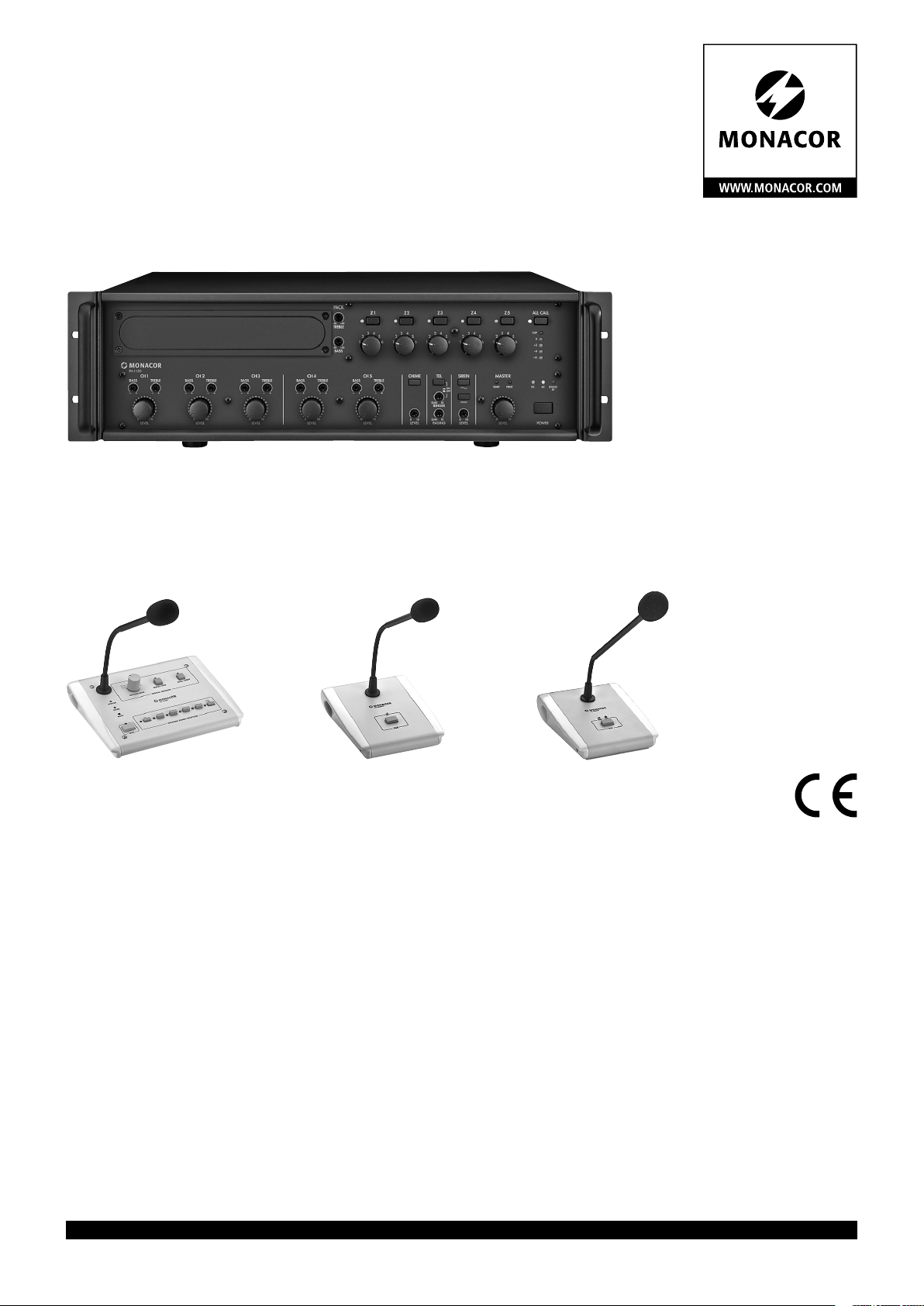
ELA-Mischverstärker für 5 Zonen
PA Mixing Amplifier for 5 Zones
PA-1120
Bestell-Nr. • Order No. 17.0780
PA-1120RC
Bestell-Nr. • Order No. 23.2440
BEDIENUNGSANLEITUNG
INSTRUCTION MANUAL
PA-1240
Bestell-Nr. • Order No. 17.0790
PA-4000PTT
Bestell-Nr. • Order No. 23.6000
PA-4300PTT
Bestell-Nr. • Order No. 23.0980
MODE D’EMPLOI
ISTRUZIONI PER L’USO
GEBRUIKSAANWIJZING
MANUAL DE INSTRUCCIONES
INSTRUKCJA OBSŁUGI
SIKKERHEDSOPLYSNINGER
SÄKERHETSFÖRESKRIFTER
TURVALLISUUDESTA
ELECTRONICS FOR SPECIALISTS ELECTRONICS FOR SPECIALISTS ELECTRONICS FOR SPECIALISTS ELECTRONICS FOR SPECIALISTS
Page 2

Deutsch ........Seite 4
English .........Page 10
Français ........Page 16
Italiano.........Pagina 22
Nederlands .....Pagina 28
Español ........Página 34
Polski ..........Strona 40
Dansk ..........Sida 46
Svenska ........Sidan 46
Suomi..........Sivulta 47
ELECTRONICS FOR SPECIALISTS ELECTRONICS FOR SPECIALISTS ELECTRONICS FOR SPECIALISTS ELECTRONICS FOR SPECIALISTS
2
Page 3
PA-1120
1 2 3 4 5 6 7
454341
29 33
51 52 58 59 66 67 68 69 70 737271
CH1
BASS TREBLE
0 10
LEVEL
CH 2
BASS TREBLE
0 10
LEVEL
CH3
BASS TREBLE
0 10
LEVEL
CH 4
BASS TREBLE
0 10
LEVEL
PACK
TREBLE
BASS
+10−10
+10−10
Z1
3
4
2
1 6
CH 5
BASS TREBLE
0 10
LEVEL
Z2 Z3 Z4 Z5 ALL CALL
5
3
2
1 6
3
4
2
5
1 6
RINGER
100
3
4
10LEAK
10LEAK
5
ON
OFF
4
2
1 6
10
0
LEVEL
5
CLIP
3
4
2
5
1 6
0
–3
–8
–13
MASTERCHIME TEL SIREN
TEMP PROT DC AC STAND
0 10
LEVEL POWERLEVEL PAGING
BY
8 9 10 11 13 14
12
TEL
SPEAKER ZONES
ATT. OUTPUTS
MESSAGE
NIGHT
RINGER
PAGING
FIRST
PRIORITY
IN
FM75 Ω
AM GND 300Ω
LOW
IMP
Z5 Z 4 Z3 Z 2 Z 1 4Ω
230V~/50 Hz
24V /15 A
POWER
POWER
REMOTE
AMP INEMERGENCY
MASTER
RECPRE OUT
L
R
0dB
LINE IN MIC/LINE IN
CH5 CH 4
GAIN
LINE MIC
–10 –50
PHANTOM
POWER
CH3
16 18 20 21 22 24 25
15 17 19 23
MIC/ LINE IN
CH2
PRIORITY
SLAVE
GAIN
LINE MIC
–10 –50
PHANTOM
POWER
LINK INPUT
DATA
REMOTE RECEIVER PA-1120RC
MIC/ LINE IN
CH1
GAIN
LINE MIC
–10 –50
PHANTOM
POWER
CHIME
PRIORITY
DATA
PA-1120RCPA-4000PTT PA-4300PTT
➀
17V
AUDIO
MIC
OFF ON
PRIORITY
CH1-3
1 2 3
ON
PRIORITY
RELAY
OUTPUT
24V
MAX. 0.2A
PA-4300PTT
UP TO 3 MICS
CONNECTED
TO CH1
PA-4000PTT
1 MIC
46444240393826 27 28 30 31 32 34 35 36 37
➁
AUDIO OUT
CHIME
PRIORITY
PTT REMOTE
21
ON
LED
PWR
7
6
3
1
4
5
2
CHIMEPRIORITY
PRIORITY
CHIME
OUTPUT LINK
MASTERMASTER
21
ON
SLAVE
47 48 49 50 53 54 55 56 57 656463626160
PA-4000PTT
TALK
PA-4300PTT
TALK BUSY
TALK
➃ ➄➂
ON
DIGITAL
MESSAGE
POWER
SEND
BUSY
TALK
CHIME
AUX IN (–10dB)
LINK OUTPUT
PRIORITY
SLAVE
OFF
TALK
4
3
2
5
6
1
MESSAGE BANK
DIGITAL MESSAGE
AUDIO
R
L
OUT
0-10
dB
REPEAT/ STOP START/STOP
PA-1120RC
PA-1120RC
Z1 Z 2 Z3 Z 4 Z 5
17V
G
PRIORITY
DATA
AUDIO
2 4 6 8
1 3 5 7
ALL
CALL
SPEAKER ZONES SELECTOR
3
Page 4

ELA-Mischverstärker für 5
Zonen
Diese Anleitung richtet sich an Installateure für
Deutsch
Beschallungsanlagen (Kapitel 1 – 10) und an Bediener ohne besondere Fachkenntnisse (Kapitel1 – 3, 8). Bitte lesen Sie die Anleitung vor dem
Betrieb gründlich durch und heben Sie sie für ein
späteres Nachlesen auf.
Auf der ausklappbaren Seite 3 finden Sie alle
beschriebenen Bedienelemente und Anschlüsse.
Inhalt
1 Übersicht . . . . . . . . . . . . . . .
1.1 Verstärker Frontseite . . . . . . . . . . .
1.2 Verstärker Rückseite. . . . . . . . . . . .
1.3 Tischmikrofon PA-4000PTT (Zubehör) . . . .
1.4 Tischmikrofon PA-4300PTT (Zubehör) . . . .
1.5 Kommandomikrofon PA-1120RC (Zubehör) . .
2 Hinweise für den sicherenGebrauch . . .
3 Einsatzmöglichkeiten undZubehör . . . .
4 Aufstellen des Verstärkers. . . . . . . .
4.1 Rackeinbau . . . . . . . . . . . . . . .
5 Gongklang und Priorität des
Einschubmoduls einstellen . . . . . . .
6 Anschlüsse herstellen . . . . . . . . . .
6.1 Lautsprecher . . . . . . . . . . . . . .
6.2 Mikrofone . . . . . . . . . . . . . . .
6.3 Tischmikrofon PA-4000PTT oder PA-4300PTT. .
6.4 Kommandomikrofon PA-1120RC. . . . . . .
6.4.1 Einbau des Anschlussmoduls . . . . . . .
6.4.2 Mikrofonanschluss und Grundeinstellung. . .
6.5 Geräte mit Line-Pegel / Tonaufnahmegerät . . .
6.6 Equalizer oder anderes Gerät einschleifen . . .
6.7 Zusätzlicher Verstärker. . . . . . . . . . .
6.8 Telefon- oder Nachtklingel . . . . . . . . .
6.9 Pflichtempfangsrelais . . . . . . . . . . .
6.10 Schalter für (automatische) Durchsagen in allen
Zonen . . . . . . . . . . . . . . . . .
6.11 Telefonzentrale. . . . . . . . . . . . . .
6.12 Ferngesteuertes Ein- und Ausschalten . . . . .
6.13 Strom- und Notstromversorgung . . . . . . .
7 Priorität der Eingangssignale festlegen. .
8 Bedienung . . . . . . . . . . . . . . .
8.1 Lautstärke einstellen . . . . . . . . . . .
8.2 Beschallungszonen aktivieren . . . . . . . .
8.3 Gong . . . . . . . . . . . . . . . . .
8.4 Alarmsirene . . . . . . . . . . . . . . .
8.5 Tischmikrofon PA-4000PTT oder PA-4300PTT. .
8.6 Kommandomikrofon PA-1120RC. . . . . . .
9 Schutzschaltung . . . . . . . . . . . .
10 Technische Daten. . . . . . . . . . . .
Lage- und Anschlussplan . . . . . . . . . . . . . . 48
Blockschaltbild
. . . . . . . . . . . . . . . . . . . 49
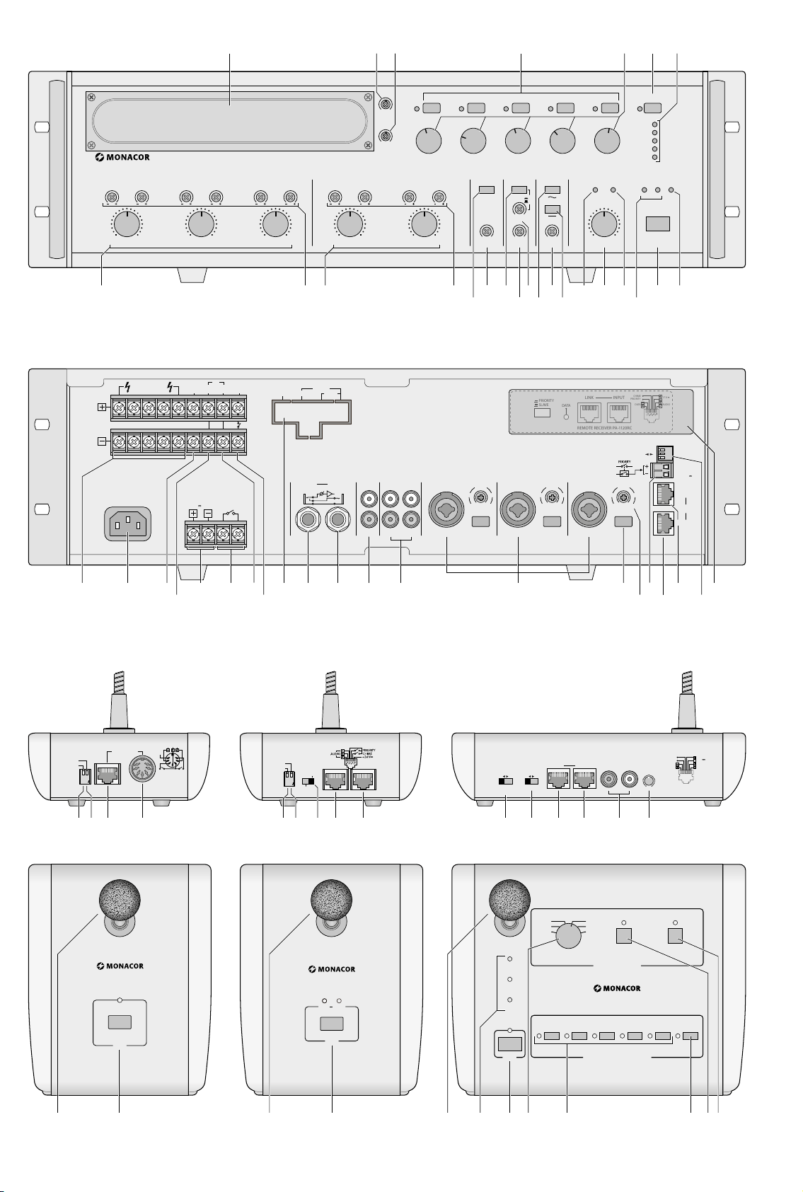
1 Übersicht
1.1 Verstärker Frontseite
1 Blende für den Einschubschacht;
hier kann ein Einschub von MONACOR eingesetzt werden, z. B. Tuner, CD-Spieler, Digital-Message-Speicher
2
Höhenregler TREBLE für ein im Schacht (1)
eingesetztes Gerät
3 Tiefenregler BASS für ein im Schacht (1) ein-
gesetztes Gerät
4 Tasten mit Kontroll-LED zum Einschalten der
einzelnen Beschallungszonen Z 1 bis Z 5
5 Zonenabschwächer für eine unterschiedliche
Lautstärkeeinstellung der einzelnen Zonen
6
Taste ALL CALL mit Kontroll-LED zum Einschal-
4
ten aller Zonen gleichzeitig und Erhöhung der
Lautstärke jeweils auf Maximum [unabhängig
4
von den Tasten (4) und den Zonenabschwä-
4
chern (5)]; die maximale Lautstärke wird nur
durch den Regler MASTER (21) begrenzt
5
7
Pegelanzeige für die Endstufe [unabhängig
5
von den Zonenabschwächern (5)];
bei Übersteuerung leuchtet die rote Anzeige
5
CLIP
5
8
Pegelregler für die Eingänge CH 1 bis CH 3 (39)
6
Mit dem Regler CH 1 wird auch der Pegel für
ein über die Buchse (43) oder (44) angeschlos-
6
senes Mikrofon eingestellt und mit dem Reg-
6
ler CH 2 der Pegel für Kommandomikrofone
des Typs PA-1120RC (angeschlossen über ein
separates Modul);
6
die Priorität dieser Eingänge lässt sich mit den
6
DIP-Schaltern (45) einstellen
9
Bass- und Höhenregler für die Eingänge CH1
6
bis CH 3 (39)
6
10 Pegelregler für die Line-Eingänge CH 4 und
6
CH5 (38)
11
Bass- und Höhenregler für die Eingänge CH4
6
und CH 5
6
12
Gongtaste; der Gong hat 2. Priorität (Zum
7
Umschalten zwischen 2-Ton- und 4-Ton-Gong
siehe Kapitel 5)
7
13 Lautstärkeregler für den Gong
7
14
Taste TEL; ist die Taste gedrückt, kann z. B.
7
eine Telefon- oder Nachtklingel über alle Lautsprecher gehört werden [Anschluss über die
7
Klemmen NIGHT RINGER (29)]; die Klingel hat
7
niedrigste Priorität
15
Lautstärkeregler für ein über die Klemmen
PAGING IN (32) eingespeistes Telefonsignal;
7
dieses Signal hat 3. Priorität
7
16 Lautstärkeregler für die Telefon- oder Nacht-
7
klingel (siehe auch Position 14 und 29)
17 Taste für einen an- und abschwellenden Sire-
8
nenton; die Sirene hat 4. Priorität
8
18 Lautstärkeregler für die Sirene
8
19 Taste für einen gleichmäßigen Sirenenton
8
20 Überhitzungsanzeige TEMP;
leuchtet, wenn die Kühlkörpertemperatur
8
100 °C erreicht. Alle Lautsprecherausgänge
8
werden dann stummgeschaltet. Zusätzlich
leuchtet die rote Anzeige PROT (22).
8
21 Regler MASTER für die Gesamtlautstärke
8
22
Anzeige PROT; leuchtet bei aktivierter Schutz-
8
schaltung:
9
9
1. ca. 1 Sekunde lang nach dem Einschalten
(Einschaltverzögerung)
2. ca. 1 Sekunde lang nach dem Ausschalten
3. wenn der Verstärker überlastet ist
4. wenn der Verstärker überhitzt ist
23 Betriebsanzeigen:
DC leuchtet, wenn der Verstärker bei Netz-
ausfall mit einer 24-V-Notversorgungsspannung arbeitet
AC leuchtet, wenn der Verstärker mit der
Netzspannung arbeitet
24 Ein-/Ausschalter POWER
25 Anzeige STAND BY;
leuchtet bei ausgeschaltetem Verstärker
1.2 Verstärker Rückseite
26
Lautsprecheranschlüsse für 100-V-Lautsprecher
Achtung! Jeder der fünf Zonenausgänge
kann durch die Lautsprecher mit maximal
100 W Sinus belastet werden. Jedoch darf
dabei die zulässige Gesamtbelastung auf
keinen Fall überschritten werden:
PA-1120
PA-1240 240 W Sinus
27
Buchse für das beiliegende Netzkabel zum
Anschluss an 230 V/ 50 Hz
28 4-Ω-Lautsprecherausgang für eine Lautspre-
chergruppe mit einer Gesamtimpedanz von
mindestens 4 Ω
Achtung! Diesen Ausgang nur verwenden,
wenn die 100-V-Ausgänge (26) nicht benutzt
werden. Anderenfalls kann der Verstärker
überlastet werden.
29
Eingang für die Klingelspannung (z. B.
8 V/ 50 Hz) einer Telefon- oder Nachtklingel;
die Klingelspannung löst ein Rufzeichen aus,
das über die Lautsprecher zu hören ist (siehe
auch Position 14 und 16)
30
Schraubanschlüsse für eine Notstromversorgung (⎓ 24 V)
31
Schraubanschlüsse für einen externen Schalter
zum ferngesteuerten Ein- und Ausschalten
[der Schalter POWER (24) darf dann nicht
gedrückt sein]
32 Eingang (sym., 250 mV) für ein Telefonsignal,
das über die ELA-Anlage zu hören sein soll
(siehe auch Position 15)
33 Anschluss für einen separaten Schalter;
über diesen lässt sich bei eingesetztem DigitalMessage-Einschub PA-1120DMT eine gespeicherte Alarmdurchsage abrufen. Gleichzeitig
werden alle Beschallungszonen eingeschaltet
und auf maximale Lautstärke gestellt [wie mit
der Taste ALL CALL (6)]
34
Abdeckblech, wird beim Einbau des Einschubs
PA-1120DMT, PA-1140RCD, PA-1200C oder
PA-1200RDSU durch eine Anschlussplatte
ersetzt
35
Eingang AMP IN in Verbindung mit dem Ausgang PRE OUT (36) zum Zwischenschalten
z. B. eines Equalizers. Beim Anschluss an diese
Buchse wird nur das hier eingespeiste Signal
wiedergegeben. Der Endverstärker ist vom
Vorverstärker abgetrennt.
36 Ausgang PRE OUT zum Anschluss eines zu-
sätzlichen Verstärkers (Kap. 6.7) oder in Verbindung mit dem Eingang AMP IN (35) zum
Zwischenschalten z. B. eines Equalizers;
die Ausgangslautstärke ist unabhängig vom
Regler MASTER (21)
37 Ausgang REC zum Anschluss eines Aufnah-
megerätes; die Ausgangslautstärke ist unabhängig vom Regler MASTER (21)
38
Eingänge CH 4 und CH 5 für Geräte mit
Line-Pegel (z. B. CD-Spieler, Kassettenrecor-
120 W Sinus
4
Page 5

der usw.); die beiden Stereokanäle L und R
werden intern zu einem Monosignal gemischt
39 symmetrische Eingänge CH 1 bis CH 3 über
XLR- / Klinkenbuchsen (Combo);
die Eingangsempfindlichkeit lässt sich mit den
Reglern GAIN (41) zwischen Mikrofon- und
Line-Pegel einstellen (2,5 – 250 mV)
40 Schalter PHANTOM POWER zum Einschalten
der 17-V-Versorgung für phantomgespeiste
Mikrofone; jeweils für die Eingänge CH 1 bis
CH3
Achtung! Wird die 17-V-Versorgung zugeschaltet, darf an der entsprechenden Eingangsbuchse (39) kein Mikrofon mit asymmetrischem Ausgang angeschlossen sein, da
dieses beschädigt werden kann.
41 Regler zum Einstellen der Eingangsempfind-
lichkeit; jeweils für die Eingänge CH 1 bis
CH3 (siehe Position 39)
42 Schraubklemmen zum Anschluss von Pflicht-
empfangsrelais, siehe Kapitel 6.9
43
Buchse PA-4000PTT zum Anschluss eines ELATischmikrofons des Typs PA-4000PTT
44
Buchse PA-4300PTT zum Anschluss eines ELATischmikrofons des Typs PA-4300PTT
45
DIP-Schalter MIC PRIORITY; in der Position ON
wird der entsprechende Eingang (CH 1, CH2
oder CH 3) von 4. auf 3. Priorität gesetzt
46 Blende; beim Einsatz des Kommandomikro-
fons PA-1120RC wird hier das Anschlussmodul montiert
1.3 Tischmikrofon PA-4000PTT
(Zubehör)
Wichtig! Für den Betrieb des Mikrofons unbedingt das Kapitel 6.3 beachten.
47 DIP-Schalter CHIME;
in der Position ON ertönt beim Drücken der
Sprechtaste TALK (52) der Gong
48 DIP-Schalter PRIORITY;
OFF: das Mikrofon hat 4. Priorität
ON: das Mikrofon hat 2. Priorität;
beim Drücken der Sprechtaste TALK
werden alle Beschallungszonen eingeschaltet sowie auf maximale Lautstärke
gestellt [wie mit Taste ALL CALL (6)]
und an den Klemmen PRIORITY RELAY
OUTPUT (42) stehen 24 V / 0,2 A max.
zum Schalten von Pflichtempfangsrelais
zur Verfügung (Kap.6.9)
49
RJ-45-Buchse zum Anschluss an die Buchse
PA-4000PTT (43) des Verstärkers
50
7-polige DIN-Buchse zum Anschluss an
einen anderen Verstärker mit entsprechender Buchse
51 Mikrofonkapsel mit Windschutz
52
Sprechtaste TALK; bei gedrückter Taste leuchtet die grüne Anzeige darüber
1.4 Tischmikrofon PA-4300PTT
(Zubehör)
Wichtig! Für den Betrieb des Mikrofons unbedingt das Kapitel 6.3 beachten.
53 DIP-Schalter CHIME;
in der Position ON ertönt beim Drücken der
Sprechtaste TALK (59) der Gong
54 DIP-Schalter PRIORITY;
OFF: das Mikrofon hat 4. Priorität
ON: das Mikrofon hat 2. Priorität;
beim Drücken der Sprechtaste TALK
werden alle Beschallungszonen eingeschaltet sowie auf maximale Lautstärke
gestellt [wie mit Taste ALL CALL (6)]
und an den Klemmen PRIORITY RELAY
OUTPUT (42) stehen 24 V / 0,2 A max.
zum Schalten von Pflichtempfangsrelais
zur Verfügung (Kap.6.9)
55
Schalter MASTER / SLAVE zum Festlegen der
Priorität beim Anschluss weiterer Mikrofone
PA-4300PTT
SLAVE andere auf MASTER geschaltete
Mikrofone haben Vorrang
MASTER das Mikrofon hat Vorrang vor Mik-
rofonen, die auf SLAVE geschaltet
sind
56 RJ-45-Buchse OUTPUT zum Anschluss an die
Buchse PA-4300PTT (44) des Verstärkers
57 RJ-45-Buchse LINK zum Anschluss eines wei-
teren Mikrofons PA-4300PTT
(max. 3 miteinander verbundene Mikrofone
können an den Verstärker angeschlossen
werden)
58 Mikrofonkapsel mit Windschutz
59
Sprechtaste TALK; bei gedrückter Taste leuchtet die grüne Anzeige TALK darüber
Die rote Anzeige BUSY leuchtet, wenn von
einem anderen PA-4300PTT gesprochen wird,
dessen Schalter MASTER / SLAVE in der Position MASTER steht.
1.5 Kommandomikrofon PA-1120RC
(Zubehör)
Für den Betrieb des PA-1120RC muss das dem
Mikrofon beiliegende Anschlussmodul eingebaut
werden (siehe Kapitel 6.4.1).
60
Schalter DIGITAL MESSAGE; in der Position
ON lassen sich gespeicherte Durchsagen abrufen*
61
Schalter TALK zum Festlegen der Priorität beim
Anschluss weiterer Mikrofone PA-1120RC
SLAVE andere auf PRIORITY geschaltete
Mikrofone haben Vorrang
PRIORITY das Mikrofon hat Vorrang vor Mik-
rofonen, die auf SLAVE geschaltet
sind
62
Buchse LINK zum Anschluss weiterer Kommandomikrofone des Typs PA-1120RC
63
Buchse OUTPUT zur Verbindung mit der
Buchse INPUT des dem Mikrofon beiliegenden Anschlussmoduls
64 Eingangsbuchsen AUX IN für ein zusätzliches
Audiosignal mit Line-Pegel
65 Ausgangspegelregler für das Mikrofonsignal
und das Signal von den Buchsen AUX IN (64)
66 Mikrofonkapsel mit Windschutz
67 Kontrollanzeigen
POWER Betriebsanzeige
(Verstärker eingeschaltet)
SEND leuchtet, wenn eine eigene Durch-
sage herausgeht oder eine gespeicherte Durchsage* abgerufen wird
BUSY leuchtet bei eigenen Durchsagen
und bei Durchsagen über andere
angeschlossene Mikrofone PA1120RC
68 Sprechtaste TALK
69 Drehschalter zur Anwahl einer gespeicherten
Durchsage*
70
Tasten Z 1 – Z 5 mit Kontroll-LEDs zum Einschalten der Zonen, in denen die Durchsage
zu hören sein soll
71
Taste ALL CALL mit Kontroll-LED zum Einschalten aller Zonen gleichzeitig [wie die Taste (6)]
72 Taste REPEAT / STOP zur mehrfachen Wieder-
gabe einer gespeicherten Durchsage*; ein
zweiter Tastendruck beendet die Durchsage
73 Taste START / STOP zur Wiedergabe einer ge-
speicherten Durchsage*; ein zweiter Tastendruck beendet die Durchsage
2 Hinweise für den
sicherenGebrauch
Das Gerät entspricht allen relevanten Richtlinien
der EU und trägt deshalb das -Zeichen.
WARNUNG
Im Betrieb liegt an den Lautsprecheranschlüssen
(26) berührungsgefährliche Spannung bis 100 V
an. Alle Anschlüsse nur bei ausgeschalteter ELAAnlage vornehmen bzw. verändern.
Im ausgeschalteten Zustand ist der Verstär-
•
ker nicht komplett von der Netzspannung
getrennt. Er verbraucht auch dann einen geringen Strom.
Das Gerät ist nur zur Verwendung in Innenräu-
•
men geeignet. Schützen Sie es vor Tropf- und
Spritzwasser, hoher Luftfeuchtigkeit und Hitze
(zulässiger Einsatztemperaturbereich 0 – 40 °C).
Stellen Sie keine mit Flüssigkeit gefüllten Ge-
•
fäße, z. B. Trinkgläser, auf das Gerät.
Die im Gerät entstehende Wärme muss durch
•
Luftzirkulation abgegeben werden. Decken Sie
die Lüftungsöffnungen nicht ab.
Nehmen Sie das Gerät nicht in Betrieb und
•
ziehen Sie sofort den Netzstecker aus der
Steckdose:
1. wenn sichtbare Schäden am Gerät oder am
Netzkabel vorhanden sind,
2.
wenn nach einem Sturz oder Ähnlichem der
Verdacht auf einen Defekt besteht,
3. wenn Funktionsstörungen auftreten.
Lassen Sie das Gerät in jedem Fall in einer Fachwerkstatt reparieren.
Ziehen Sie den Netzstecker nie am Kabel aus
•
der Steckdose, fassen Sie immer am Stecker
an.
Verwenden Sie zum Reinigen nur ein trocke-
•
nes, weiches Tuch, niemals Wasser oder Chemikalien.
Wird das Gerät zweckentfremdet, nicht rich-
•
tig angeschlossen, falsch bedient oder nicht
fachgerecht repariert, kann keine Garantie
für das Gerät und keine Haftung für daraus
resultierende Sach- oder Personenschäden
übernommen werden.
* Funktion nur bei eingebautem Digital-Message-Ein-
schub PA-1120DMT möglich
Das Gerät wird mit lebensgefährlicher Netzspannung versorgt. Neh
men Sie deshalb niemals selbst
Eingriffe am Gerät vor und stecken
Sie nichts durch die Lüftungsöffnungen! Es besteht die Gefahr
eines elektrischen Schlages.
Soll das Gerät endgültig aus dem Betrieb genommen werden, übergeben
Sie es zur umweltgerechten Entsorgung
einem örtlichen Recyclingbetrieb.
Deutsch
-
5
Page 6

3 Einsatzmöglichkeiten
undZubehör
Dieser Verstärker ist speziell für den Einsatz in
Deutsch
100-V-ELA-Anlagen konzipiert. Es stehen 100-VAusgänge für bis zu fünf Beschallungszonen zur
Verfügung, deren Lautstärke sich individuell einstellen lässt. Über drei Eingänge mit unterschiedlich einstellbarer Priorität können Mikrofone oder
Geräte mit Line-Pegel angeschlossen werden.
Zwei weitere Line-Eingänge mit niedrigster Priorität ergänzen die Anschlussmöglichkeiten.
Zubehör
Einschubmodule für den Erweiterungsschacht (1)
PA-1120DMT
PA-1140RCD
PA-1200C Schaltuhr
PA-1200RDSU
ELA-Tischmikrofone speziell für diesen Verstärker
PA-4000PTT
(Abb. 3)
PA-4300PTT
(Abb. 4)
PA-1120RC
(Abb. 5)
Digital-Message-Speicher
mitSchaltuhr
Radio / CD-Spieler
AM / FM-Radio mit Audiospieler
Ein Tischmikrofon lässt sich an die
Buchse PA-4000PTT (43) anschließen.
Ein Tischmikrofon lässt sich an die
Buchse PA-4300PTT (44) anschließen. Insgesamt können drei
PA-4300PTT mit dem Verstärker
betrieben werden.
Es lassen sich drei Kommandomikrofone anschließen; dem Mikrofon
liegt ein Anschlussmodul bei, das in
den Verstärker eingesetzt wird.
4 Aufstellen des Verstärkers
Der Verstärker ist für den Einschub in ein Rack
(482 mm / 19”) vorgesehen, kann aber auch als
Tischgerät verwendet werden. In jedem Fall muss
Luft ungehindert durch alle Lüftungsöffnungen
strömen können, damit eine ausreichende Kühlung der Endstufe gewährleistet ist.
4.1 Rackeinbau
Für die Rackmontage werden 3 HE (3 Höheneinheiten = 133 mm) benötigt. Damit das Rack nicht
kopflastig wird, muss der Verstärker im unteren
Bereich des Racks eingeschoben werden. Für eine
sichere Befestigung reicht die Frontplatte allein
nicht aus. Zusätzlich müssen Seitenschienen oder
eine Bodenplatte das Gerät halten.
Die vom Verstärker seitlich ausgeblasene,
erhitzte Luft muss ungehindert aus dem Rack
strömen können. Anderenfalls kommt es im Rack
zu einem Hitzestau, wodurch nicht nur der Verstärker, sondern auch weitere Geräte beschädigt
werden können. Bei unzureichendem Wärmeabfluss in das Rack über dem Verstärker eine
Lüftereinheit einsetzen (z. B. DPVEN-04).
5 Gongklang und Priorität des
Einschubmoduls einstellen
Vor dem Einbau eines Einschubs in den Schacht
(1) die beiden Steckbrücken MS 1 (Gongklang)
und MS 2 (Priorität des Einschubs) einstellen,
siehe Lageplan Seite 48. Diese sind bei einem
eingebauten Einschub nicht mehr zugänglich.
1)
Den Verstärker vom Netz und von der Notstromversorgung trennen.
2)
Die Blende (1) für den Einschub abschrauben.
3)
Den Gongklang mit der Brücke MS 1 einstellen:
Position „4 Tone“: 4-Ton-Gong
Position „2 Tone“: 2-Ton-Gong
4)
Die Priorität für das Einschubmodul mit der
Brücke MS 2 einstellen:
Position „SLAVE“ (Werkseinstellung):
Das Signal vom Einschub hat niedrigste Priorität.
Position „PRI“:
Das Signal vom Einschub hat 2. Priorität. Diese
Einstellung muss z. B. gewählt werden, wenn
über das Kommandomikrofon PA-1120RC
gespeicherte Durchsagen vom Digital-Message-Speicher PA-1120DMT abgerufen werden sollen.
Eine Übersicht aller möglichen Prioritäten wird
im Kapitel 7 „Priorität der Eingangssignale
festlegen“ gegeben.
5)
Falls kein Einschub eingebaut wird, die Blende
(1) wieder festschrauben.
6 Anschlüsse herstellen
Alle Anschlüsse sollten nur durch eine qualifizierte Fachkraft und unbedingt bei ausgeschaltetem Verstärker vorgenommen werden!
6.1 Lautsprecher
Entweder 100-V-Lautsprecher für die fünf
Beschallungszonen an die Schraubklemmen
SPEAKER ZONES ATT. OUTPUTS (26) anschließen
Achtung! Jeder der fünf Zonenausgänge kann
durch die Lautsprecher mit maximal 100 W
Sinus belastet werden. Jedoch darf dabei die
zulässige Gesamtbelastung auf keinen Fall überschritten werden:
PA-1120 120 W Sinus
PA-1240 240 W Sinus
oder eine Lautsprechergruppe mit einer Gesamtimpedanz von mindestens 4 Ω an die
Schraubklemmen LOW IMP 4 Ω (28) anschließen. Die Zonenlautstärkeschalter (5) beeinflussen diesen Ausgang nicht. Auf keinen Fall die
100-V-Ausgänge (26) und den 4-Ω-Ausgang (28)
gleichzeitig benutzen, sonst wird der Verstärker
überlastet!
Beim Anschluss der Lautsprecher immer auf
die richtige Polarität achten, d. h. den Plusanschluss
der Lautsprecher jeweils mit der oberen Klemme
verbinden. Der Plusanschluss der Lautsprecherkabel ist immer besonders gekennzeichnet.
6.2 Mikrofone
Drei Mikrofone mit einem XLR- oder 6,3-mm-Klinkenstecker lassen sich an die XLR / Klinken-Kombibuchsen (39) der Eingänge CH 1 – 3 anschließen.
1) Beim Anschluss eines Mikrofons den dazuge-
hörigen Regler GAIN (41) ganz nach rechts in
die Position „−50” drehen.
2)
Bei Verwendung eines phantomgespeisten
Mikrofons die 17-V-Versorgung mit der entsprechenden Taste PHANTOM POWER (40)
einschalten.
Vorsicht! Den Schalter nur bei ausgeschalte-
tem Verstärker betätigen (Schaltgeräusche).
Bei gedrückter Taste darf am zugehörigen
Eingang kein Mikrofon mit asymmetrischem
Ausgang angeschlossen sein, da dieses beschädigt werden kann.
3)
Soll ein Mikrofon Vorrang vor einem anderen Mikrofon erhalten, den zugehörigen
DIP-Schalter MIC PRIORITY (45) in die Position
ON stellen (siehe auch Kap. 7).
Hinweise:
1. Wird das Tischmikrofon PA-4000PTT (Abb. 3) oder PA-
4300PTT (Abb. 4) verwendet, darf der Eingang CH1
nicht benutzt werden, weil dieser mit dem Eingang
(43) für das PA-4000PTT und mit dem Eingang (44)
für das PA-4300PTT parallelgeschaltet ist.
2. Ist ein Kommandomikrofon PA-1120RC angeschlossen, darf der Eingang CH 2 nicht benutzt werden, weil
dieser mit dem Eingang für das PA-1120RC (über das
zugehörige Anschlussmodul) parallelgeschaltet ist.
6.3 Tischmikrofon PA-4000PTT oder
PA-4300PTT
Die als separates Zubehör lieferbaren Tischmikrofone PA-4000PTT (Abb. 3) und PA-4300PTT
(Abb. 4) sind speziell für diesen Verstärker
konzipiert.
1) Das Mikrofon PA-4000PTT über seine RJ-45-
Buchse PTT REMOTE (49) mit der Buchse PA4000PTT (43) am Verstärker verbinden oder
das Mikrofon PA-4300PTT über seine Buchse
OUTPUT (56) mit der Buchse PA-4300PTT (44)
des Verstärkers.
2)
Von dem Modell PA-4300PTT lassen sich noch
zwei weitere Mikrofone anschließen: Die
Buchse LINK (57) des ersten Mikrofons mit der
Buchse OUTPUT (56) des zweiten Mikrofons
verbinden. Das dritte Mikrofon genauso an
das zweite Mikrofon anschließen.
3)
Die Taste PHANTOM POWER (40) des Eingangs
CH 1 drücken und den dazugehörigen Regler
GAIN (41) ganz nach rechts in die Position
„−50” drehen.
Hinweise:
1. Der Eingang CH 1 darf jetzt nicht für andere Eingangssignale benutzt werden, weil dieser mit den Buchsen
für die Tischmikrofone parallelgeschaltet ist.
2. Die Gesamtlänge des Mikrofonkabels darf maximal
1000 m betragen.
6.4 Kommandomikrofon PA-1120RC
Das als separates Zubehör lieferbare Kommandomikrofon PA-1120RC (Abb. 5) ist speziell für
diesen Verstärker konzipiert. Es können bis zu
drei Kommandomikrofone angeschlossen werden. Zum Betrieb muss zuerst das dem Mikrofon
beiliegende Anschlussmodul in den Verstärker
eingesetzt werden. Dieses darf nur durch eine
qualifizierte Fachkraft erfolgen!
Hinweis: Bei Verwendung des Kommandomikrofons
darf der Eingang CH 2 nicht für andere Eingangssignale
benutzt werden, weil dieser mit dem Eingang für das
Kommandomikrofon parallelgeschaltet ist.
6.4.1 Einbau des Anschlussmoduls
1)
Den Netzstecker aus der Steckdose ziehen.
Falls eine Notstromeinheit angeschlossen ist,
diese von den Anschlüssen 24 V⎓ (30) trennen, damit der Verstärker auf jeden Fall außer
Betrieb ist. Den Gehäusedeckel des Verstärkers
sowie die Blende (46) auf der Verstärkerrückseite abschrauben.
2)
Die 3-polige Leitung AS 903 C des Anschlussmoduls in die Buchse CN 903 C des Verstärkers stecken – siehe Lageplan Seite 48
3) Das Modul in die durch die Blende (46) frei-
gegebenen Aussparungen einsetzen und
festschrauben.
4)
Die im Verstärker frei liegende, zweipolige Leitung A mit einer schwarzen und roten Ader
vom Anschluss AS 801 in die Buchse CN 801
A des Moduls stecken.
5)
Die abgeschirmte Leitung AS 802 B des
Moduls in die Buchse AN 802 B des Verstärkers stecken.
6)
Die 6-polige Leitung AS 204 D des Moduls in
die Buchse CN 901 D des Verstärkers stecken.
7)
Ist kein Digital-Message-Einschub PA1120DMT eingebaut, die lose 10-polige Lei-
.
6
Page 7
tung AS 4-1 des Moduls mit Kabelbindern im
Switch Line
Audio Line
PA-4000PTT
TEL
Verstärker befestigen.
Die Punkte 8) bis 10) nur bei eingebautem Digital-Message-Einschub PA-1120DMT durchführen:
8)
Die 10-polige Leitung AS 4-1 des Moduls in die
Buchse CN 4-1 des Einschubs stecken.
9) Mit der Brücke MS 802 des Anschlussmoduls
festlegen, ob die Durchsage im Speicher M 6
des PA-1120DMT über das Kommandomik
rofon abgerufen werden kann (Position ON)
oder nicht (Position OFF, Werkseinstellung).
Der Speicher M6 kann z. B. für eine Alarmdurchsage genutzt werden, die nur über die
Klemmen MESSAGE FIRST PRIORITY (33)
aktiviert werden soll.
10)
Im Verstärker die Brücke MS 2 in die Position
PRI setzen. Dadurch wird eine Durchsage vom
Einschub nicht durch ein Signal des Kommandomikrofons in der Lautstärke abgesenkt.
6.4.2 Mikrofonanschluss und
Grundeinstellung
1)
Die Buchse OUTPUT (63) des Mikrofons mit der
Buchse INPUT des Anschlussmoduls verbinden.
Ein kurzes Anschlusskabel liegt dem Mikrofon
bei. Die Kabellänge zwischen Verstärker und
Mikrofon darf max. 1000 m betragen.
Ein 2. Mikrofon kann über seine Buchse
OUTPUT an die Buchse LINK des Moduls oder
an die Buchse LINK (62) des 1. Mikrofons angeschlossen werden. Zum Anschluss eines 3.
Mikrofons dessen Buchse OUTPUT mit der
Buchse LINK des 2. Mikrofons verbinden.
Maximal können drei Mikrofone angeschlossen werden. Die Kabellänge zwischen zwei
Mikrofonen darf 100 m nicht überschreiten.
2)
Beim Einsatz mehrerer Mikrofone des Typs
PA-1120RC an dem Mikrofon bzw. an den
Mikrofonen, die Vorrang vor den übrigen erhalten sollen, den Schalter TALK (61) in die
Position PRIORITY schieben. Bei den übrigen
Mikrofonen den Schalter in die Position SLAVE
schieben. Dadurch kann eine Durchsage von
einem Mikrofon ohne Vorrang durch ein
Mikrofon mit Vorrang unterbrochen werden.
3) Um für das Kommandomikrofon bzw. für die
Kommandomikrofone 2. Priorität zu erhalten,
die Taste am Anschlussmodul drücken (Position PRIORITY). Bei nicht gedrückter Taste
(Position SLAVE) ist 4. Priorität eingestellt.
4)
Wird der Digital-Message-Einschub PA1120DMT verwendet, mit dem Schalter DIGITAL MESSAGE (60) wählen, ob über das
Kommandomikrofon gespeicherte Durchsagen abgerufen werden können (Schalterposition ON) oder gesperrt sind (Position OFF).
5) Wenn die Eingänge am Verstärker nicht ausreichen, kann über die Buchsen AUX IN (64)
ein Line-Signal eingespeist werden (z. B. Hintergrundmusik von einem CD-Spieler). Den
Ausgangspegel für das Mikrofonsignal und
das Signal von den Buchsen AUX IN mit dem
Regler AUDIO OUT (65) einstellen.
6.5 Geräte mit Line-Pegel /
Tonaufnahmegerät
Bis zu fünf Geräte mit Line-Pegel (z. B. CD-Spieler,
Kassettenrecorder) lassen sich an die Eingänge
CH 1 bis CH 3 (39) sowie CH 4 und CH 5 (38)
anschließen. Ausnahmen: CH 1 nicht benutzen
beim Betrieb des Tischmikrofons PA-4000PTT
oder PA-4300PTT und CH 2 nicht benutzen beim
Betrieb des Kommandomikrofons PA-1120RC!
Für Hintergrundmusik sollten die Eingänge
CH4 und CH 5 verwendet werden, weil diese
niedrigste Priorität haben.
1) Beim Anschluss der Eingänge CH 1 bis CH 3
den dazugehörigen Regler GAIN (41) ganz
nach links in die Position „−10“ drehen. Die
entsprechende Taste PHANTOM POWER (40)
nicht drücken.
Beim Anschluss eines Stereo-Gerätes an
einen der Eingänge CH 1 bis CH 3 einen Stereo-Mono-Adapter (z. B. SMC-1 von MONACOR) und ein Adapterkabel (z. B. MCA-300
von MONACOR) verwenden, sonst löschen
sich die Signale der Stereomitte gegenseitig
aus.
2) Soll von den Eingängen CH 1 bis CH 3 einer
Vorrang vor den anderen beiden erhalten, den
entsprechenden DIP-Schalter MIC PRIORITY
(45) in die Position ON stellen. Die Eingänge
CH 1 bis CH 3 haben immer Vorrang vor den
Eingängen CH 4 und CH 5 (siehe auch Kapitel 7).
3) Ein Tonaufnahmegerät kann an die Buchsen
REC (37) angeschlossen werden. Die Aufnahmelautstärke ist vom Regler MASTER (21) und
den Zonenabschwächern (5) unabhängig.
6.6 Equalizer oder anderes Gerät
einschleifen
Zur externen Klangbeeinflussung lässt sich z. B.
ein Equalizer über die Buchsen AMP IN (35) und
PRE OUT (36) einschleifen: Den Eingang des Gerätes an die Buchse PRE OUT anschließen und
den Ausgang an die Buchse AMP IN.
Hinweis: Im Verstärker entsteht eine Signalunterbrechung, wenn nur die Buchse AMP IN angeschlossen ist
oder das eingeschleifte Gerät nicht eingeschaltet, defekt
oder nicht richtig angeschlossen ist. Die Lautsprecher
bleiben dann stumm.
6.7 Zusätzlicher Verstärker
Werden mehr Lautsprecher benötigt, als für den
Verstärker zulässig sind, ist ein weiterer Verstärker
erforderlich. Den Eingang des zusätzlichen Verstärkers mit der Buchse PRE OUT (36) oder REC
(37) verbinden. Das Signal für den Zusatzverstärker wird nicht durch den Regler MASTER (21) und
durch die Zonenlautstärkeschalter (5) beeinflusst.
6.8 Telefon- oder Nachtklingel
Eine Telefon- oder Nachtklingel kann bei Bedarf
über die ELA-Anlage ertönen (z. B. während eines
nächtlichen Kontrollrundgangs).
1) Das Signal für die Klingel (z. B. 8 V/ 50 Hz) auf
die Klemmen NIGHT RINGER (29) geben.
2) Die Taste TEL (14) drücken.
3) Die Klingel auslösen und mit dem Regler RINGER (16) die Lautstärke des vom Verstärker
erzeugten Rufzeichens einstellen.
4) Die Ruffunktion mit der Taste TEL je nach Bedarf ein- oder ausschalten.
Hinweis: Die Klingel hat niedrigste Priorität.
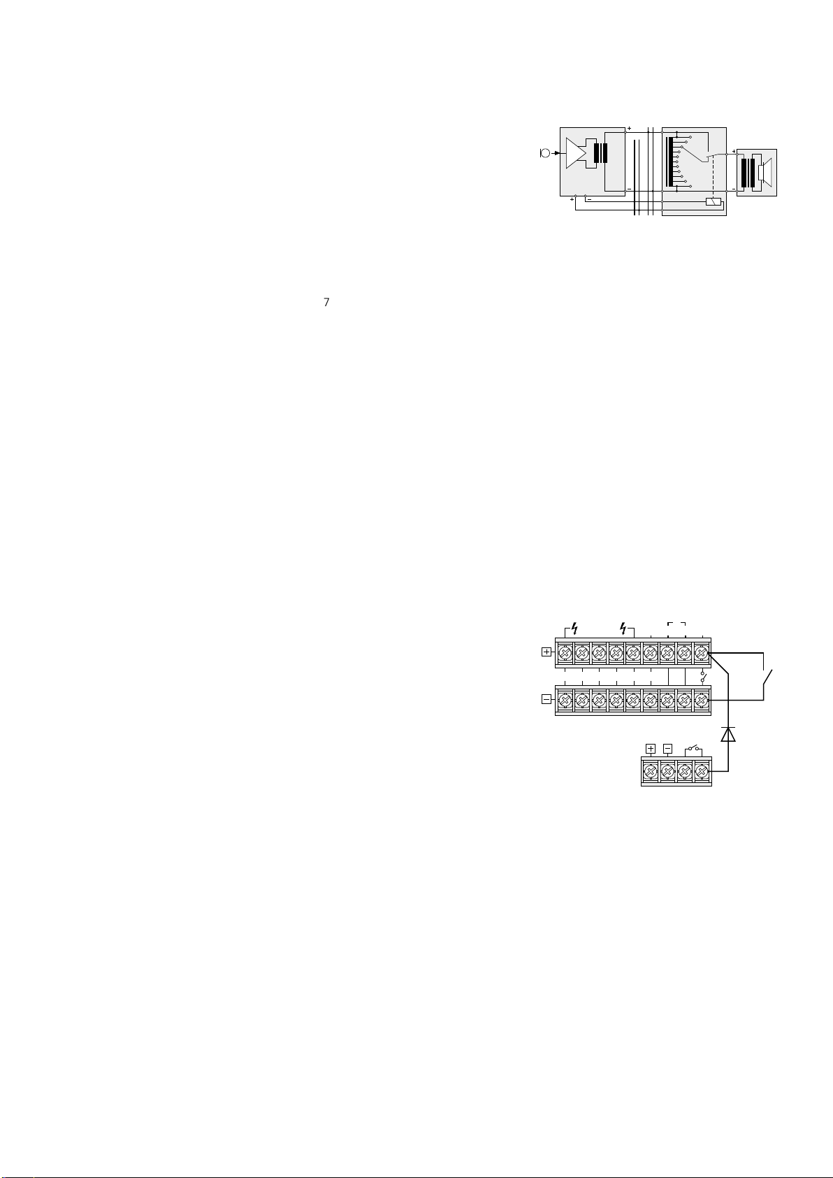
6.9 Pflichtempfangsrelais
Sind zwischen dem Verstärker und den Lautsprechern ELA-Lautstärkeeinsteller mit Pflichtemp
fangsrelais (z. B. Serie ATT-3..PEU oder ATT-5..PEU
von MONACOR) geschaltet, können wichtige
Durch sagen auch bei eingestellter Lautstärke
„Null“ gehört werden.
1)
Dazu ein Tischmikrofon PA-4000PTT oder
PA-4300PTT anschließen (siehe Kap. 6.3).
2) Die Pflichtempfangsrelais nach der Abb. 6 an
die Schraubklemmen PRIORITY RELAY OUTPUT (42) anschließen. Der Ausgang ist mit
200 mA belastbar.
3) Am Mikrofon den Schalter PRIORITY (48, 54)
in die Position ON (nach unten) stellen.
4)
Beim Betätigen der Sprechtaste TALK (52, 59)
werden jetzt durch die Relais die Lautsprecher
auf maximale Lautstärke geschaltet.
ATT-…PA-1120/PA-1240
10
100V
PRIORITY RELAY
OUTPUT
24 V, max. 0,2 A
PA-4300PTT
Pflichtempfangsrelais
➅
24 V
100 V
0
6.10 Schalter für (automatische)
Durchsagen in allen Zonen
Zur Fernsteuerung der folgenden Funktionen
einen Schalter an die Klemmen MESSAGE FIRST
PRIORITY (33) anschließen:
1. Alle Beschallungszonen werden eingeschaltet
und auf maximale Lautstärke gestellt [wie Taste
ALL CALL (6)].
2. Bei Verwendung des Digital-Message-Ein-
schubs PA-1120DMT wird automatisch die
Durchsage des Speichers M 6 abgerufen. Dazu
die Brücke MS 2 vor dem Einbau des Einschubs
in die Position PRI stellen (siehe Lageplan auf
). Dadurch erhält die Durchsage des
Seite 48
Speichers M 6 erste Priorität.
Anstelle des Schalters kann auch ein Alarmmeldekontakt angeschlossen werden, z. B. für
eine automatische Feueralarmdurchsage.
3. Soll durch den Schalter bzw. durch den Alarm-
meldekontakt der Verstärker auch gleichzeitig eingeschaltet werden, eine Diode vom
Typ 1N4004 nach Abb. 7 zwischen die obere
Klemme MESSAGE FIRST PRIORITY und die
rechte Klemme POWER REMOTE schalten.
SPEAKER ZONES
ATT- OUTPUTS
Z5 Z4 Z3 Z2 Z1 4Ω
Automatisches Einschalten des Verstärkers
➆
und Aktivieren der Durchsage M 6
LOW
IMP
24V⎓/27A
NIGHT
RINGER
MESSAGE
FIRST
PAGING
PRIORITY
IN
POWER
MAX
REMOTE
6.11 Telefonzentrale
Von einer Telefonzentrale lassen sich Durchsagen
über die ELA-Anlage wiedergeben.
1)
Das Telefonsignal (Line-Pegel) auf die Klemmen PAGING IN (32) geben.
2)
Während einer Durchsage mit dem Regler
PAGING (15) die Lautstärke einstellen.
Hinweis: Telefondurchsagen haben 3. Priorität.
-
6.12 Ferngesteuertes Ein- und
Ausschalten
Der Verstärker lässt sich über einen separaten
Schalter ferngesteuert ein- und ausschalten.
1) Die Schraubanschlüsse POWER REMOTE (31)
über eine zweipolige Leitung mit einem einpoligen Ein- /Ausschalter verbinden.
2)
Zum ferngesteuerten Ein- und Ausschalten
darf der Hauptschalter POWER (24) nicht gedrückt sein.
Deutsch
Speaker
1N4004
7
Page 8

6.13 Strom- und Notstromversorgung
1) Soll der Verstärker bei einem Netzausfall weiterarbeiten, an die Klemmen 24 V⎓ (30) eine
24-V-Notstromeinheit (z. B. PA-24ESP von
Deutsch
MONACOR) anschließen. Bei einer Kabellänge
von bis zu 7 m ist ein Kabelquerschnitt von
mindestens 4 mm2 erforderlich.
2)
Zum Schluss das beiliegende Netzkabel zuerst in die Netzbuchse (27) und dann in eine
Steckdose (230 V/ 50 Hz) stecken.
Hinweis: Auch wenn der Verstärker ausgeschaltet ist,
verbraucht er einen geringen Strom. Darum den Netzstecker aus der Steckdose ziehen und ggf. die Notstromeinheit abklemmen, wenn der Verstärker längere Zeit
nicht betrieben wird.
7 Priorität der
Eingangssignale festlegen
Allen Eingangssignalen ist eine Priorität zugewiesen. Ein Signal mit einer höheren Priorität überdeckt immer ein Signal mit niedriger Priorität,
wenn beide Signale gleichzeitig am Verstärker
anliegen. (Die Signale mit gleicher Priorität werden gemischt.) Die folgende Tabelle gibt eine
Übersicht und zeigt Änderungsmöglichkeiten.
Priorität
Signal Bedingung Änderung
Durchsage M 6
vom Digital-Mes-
1
sage-Einschub
PA-1120DMT
Tischmikrofon
PA-4000PTT
PA-4300PTT
2
Kommandomikrofon
PA-6000RC
Gong — —
Telefonzentrale an
3
Klemme (32)
Eingänge CH 1,
CH2 und CH 3
4
Sirene — —
Ergänzungseinschübe
5
Eingänge 4 und 5 — —
Telefon- oder
Nachtklingel
1. Werkseinstellung
2. Das Tischmikrofon PA-4000PTT/ PA-4300PTT belegt
den Eingang CH 1 und das Kommandomikrofon
PA-1120RC den Eingang CH 2. Über den zugehörigen
DIP-Schalter MIC PRIORITY (45) können die Mikrofone
auch auf 3. Priorität gestellt werden.
Brücke MS 2
auf PRI
Schalter an
(33) geschlossen
DIP-Schalter
PRIORITY (48,
54) auf ON
Schalter am
Anschlussmodul auf
PRIORITY
— —
DIP-Schalter (45) auf
1
OFF
Brücke MS 2
1
auf SLAVE
— —
Schalter auf
OFF =
4.Priorität
Schalter auf
SLAVE =
4.Priorität
DIP-Schalter
auf ON =
3.Priorität
Brücke MS 2
auf PRI =
2.Priorität
8 Bedienung
Ist der Verstärker ausgeschaltet und liegt die
Netz- oder die Notversorgungsspannung an,
leuchtet die Anzeige STAND BY (25).
1)
Vor dem ersten Einschalten zunächst alle fünf
Eingangsregler LEVEL (8 und 10) sowie den
Regler MASTER (21) in die Position “0” stellen.
2) Mit dem Schalter POWER (24) den Verstärker
einschalten. Die Anzeige STAND BY erlischt
und die Anzeige AC (23) leuchtet. Bei einem
Netzausfall und anliegender Notstromversorgung leuchtet die Anzeige DC anstelle der
AnzeigeAC.
8.1 Lautstärke einstellen
1)
Zuerst die maximal gewünschte Lautstärke für
Durchsagen oberster Priorität einstellen. Dazu
vorerst die Taste ALL CALL (6) drücken. Je nach
Ausstattung die Durchsage durchführen:
a)
Bei vorhandenem Digital-Message-Einschub über einen Schalter an den Klemmen
MESSAGE FIRST PRIORITY (33) die Durchsage aus dem Speicher M 6 abrufen. Den
Pegelregler LEVEL am Einschub ungefähr in
die Position 7 stellen.
b)
Bei vorhandenem Tischmikrofon PA4000PTT oder PA-4300PTT den zugehörigen Regler LEVEL (8) des Eingangs CH 1
ungefähr in die Position 7 stellen und eine
Ansage durchgeben.
c)
Bei vorhandenem Kommandomikrofon PA1120RC den zugehörigen Regler LEVEL (8)
des Eingangs CH 2 ungefähr in die Position
7 stellen und eine Ansage durchgeben.
d) Bei Verwendung eines anderen Mikrofons
den dazugehörigen Regler LEVEL (8) ungefähr in die Position 7 stellen und eine
Ansage durchgeben.
2)
Während der Durchsage mit dem Regler MASTER (21) die Lautstärke einstellen. Bei Übersteuerung leuchtet in der Pegelanzeige (7) die
rote LED CLIP. Dann die Lautstärke mit dem
Regler MASTER reduzieren.
3)
Um die Lautstärke für normale Durchsagen
einzustellen, die Taste ALL CALL wieder ausrasten. Dafür alle Tasten (4) der einzelnen
Beschallungszonen drücken.
4) Eine Ansage wie unter Punkt 1) b oder d beschrieben durchgeben.
Hinweise:
2
2
Am PA-4000PTT/ PA-4300PTT den Schalter PRIORITY
(48, 54) in die obere Position stellen.
Die Ansage nicht über ein PA-1120RC durchgeben,
weil dessen Lautstärke unabhängig von den Zonenlautstärkeschaltern (5) ist.
5)
Den Regler MASTER (21) nicht verändern,
sondern während der Durchsage mit den
entsprechenden Zonenabschwächern (5) für
jede Zone getrennt die gewünschte Lautstärke
einstellen.
6) Anschließend für die Signale der übrigen Eingänge (z. B. Hintergrundmusik) die Lautstärke
mit dem dazugehörigen Regler LEVEL (8 oder
10) einstellen.
7)
Für jeden verwendeten Eingang den Klang
mit den entsprechenden Reglern BASS und
TREBLE (9 und 11) einstellen. Den Klang für
ein Einschubmodul im Schacht (1) mit den
Reglern PACK (2 und 3) einstellen.
8) Eventuell kann es erforderlich sein, die Lautstärke der Eingangssignale mit den entsprechenden Reglern (8 bzw. 10) noch einmal
nachzuregeln.
9) Nicht verwendete Eingänge mit den entsprechenden Reglern auf „0” stellen.
Hinweis: Bei den Eingängen CH 1 bis CH 3 lässt sich
die Eingangsempfindlichkeit mit den Reglern GAIN (41)
einstellen. Muss ein Pegelregler (8) sehr weit auf- oder
fast zugedreht werden, um das gewünschte Lautstärkeverhältnis zu den anderen Eingängen zu erhalten, die
Eingangsempfindlichkeit mit dem zugehörigen Regler
GAIN verändern.
8.2 Beschallungszonen aktivieren
1)
Mit den Tasten Z 1 – Z 5 (4) die Zonen einschalten, die beschallt werden sollen. Zur Kontrolle leuchten die grünen LEDs der aktivierten
Zonen.
2) Für Durchsagen an alle Zonen die Taste ALL
CALL (6) drücken. Gleichzeitig wird die Lautstärke der Zonen auf Maximum angehoben
[entspricht dem Einstellen aller Zonenabschwächer (5) in die Position 6].
8.3 Gong
Durch Betätigung der Sprechtaste TALK (52, 59,
68) am Mikrofon PA-4000PTT, PA-4300PTT bzw.
PA-1120RC ertönt vor einer Durchsage der Gong.
Bei Verwendung anderer Mikrofone lässt sich der
Gong auch mit der Taste CHIME (12) auslösen.
Die Gonglautstärke mit dem Regler LEVEL (13)
einstellen.
Mit der Steckbrücke MS 1 kann zwischen
einem 2-Ton- und 4-Ton-Gong umgeschaltet
werden, siehe Kapitel 5.
8.4 Alarmsirene
Bei einem Alarm lässt sich im Bedienfeld SIREN
eine der beiden Sirenen einschalten:
Taste „~” (17) für einen an- und abschwellen-
den Ton
Taste „–” (19) für einen gleichmäßigen Dauerton
Die Lautstärke des Alarmtons mit dem Regler
LEVEL (18) einstellen.
8.5 Tischmikrofon PA-4000PTT oder
PA-4300PTT
1)
Ist das Mikrofon PA-4000PTT oder PA-4300PTT
angeschlossen, ist damit der Eingang CH 1
belegt. Weil das Mikrofon zum Betrieb eine
Phantomspannung benötigt, die Taste PHANTOM POWER (40) des Eingangs CH 1 drücken.
2)
Soll beim Betätigen der Sprechtaste TALK (52,
59) vor einer Durchsage der Gong ertönen,
den Schalter CHIME (47, 53) auf der Rückseite des Mikrofons in die Position ON (nach
unten) stellen.
3)
Den Schalter PRIORITY (48, 54) in die Position
ON stellen, wenn:
1. das Mikrofon 2. Priorität erhalten soll
2. beim Drücken der Sprechtaste TALK alle
Beschallungszonen eingeschaltet und auf
maximale Lautstärke gestellt werden sollen
[wie mit Taste ALL CALL (6)]
3. die Pflichtempfangsrelais schalten sollen
(siehe Kap. 6.9)
4) Für eine Durchsage die Sprechtaste TALK (52,
59) gedrückt halten und ggf. den Gong ab-
warten. Die grüne Kontrollanzeige leuchtet
bei gedrückter Sprechtaste.
5)
Sind zwei oder drei Mikrofone PA-4300PTT
angeschlossen, kann für die Mikrofone eine
unterschiedliche Priorität mit dem Schalter
MASTER / SLAVE (55) festgelegt werden:
SLAVE andere auf MASTER geschaltete
Mikrofone haben Vorrang
MASTER das Mikrofon hat Vorrang vor Mikro-
fonen, die auf SLAVE geschaltet sind
Die rote Anzeige BUSY über der Taste TALK
leuchtet, wenn von einem anderen PA4300PTT gesprochen wird, dessen Schalter
MASTER /SLAVE in der Position MASTER steht.
8.6 Kommandomikrofon PA-1120RC
1)
Zuerst die Beschallungszonen, in denen die
Durchsage zu hören sein soll, mit den Tasten
SPEAKER ZONES SELECTOR (70) einschalten,
sonst ist keine Durchsage möglich. Zum Aktivieren aller Zonen die Taste ALL CALL (71)
drücken.
2)
Zur Durchsage die Sprechtaste TALK (68)
gedrückt halten. Der Verstärker aktiviert die
Beschallungszonen entsprechend der Vorwahl
unter Punkt 1) unabhängig von den Einstellungen am Verstärker und erhöht die Lautstärke
in den Zonen auf Maximum [entspricht dem
Einstellen aller Zonenlautstärkeschalter (5) in
8
Page 9

die Position 6]. Nach dem Gong die Ansage
durchgeben.
3)
Bei Einsatz des Digital-Message-Einschubs PA1120DMT lässt sich eine gespeicherte Durchsage auch über das Kommandomikrofon abrufen, wenn der Schalter DIGITAL MESSAGE
(60) in der Position ON steht:
a)
Mit dem Wahlschalter MESSAGE BANK (69)
die gespeicherte Durchsage auswählen.
b) Mit der Taste START/ STOP (73) die Durch-
sage starten. Zum Abbrechen der Durchsage die Taste START/ STOP erneut drücken.
c) Mit der Taste REPEAT/ STOP (72) kann eine
Durchsage auch mehrere Male durchgegeben werden. Die Anzahl der Wiederholungen und die Zwischenpausen sind am
Einschub einzustellen (siehe dessen Bedienungsanleitung). Zum Abbrechen der
Durchsage die Taste REPEAT/ STOP erneut
betätigen.
Hinweise:
1. Die Durchsage des Speichers M 6 kann gesperrt
sein (siehe Kap. 6.4.1, Punkt 9). Steht in diesem
Fall der Schalter MESSAGE BANK in der Position
6, wird dann die zuvor angewählte Durchsage
wiedergegeben.
2. Ist am Verstärker mindestens eine Zonentaste (4)
gedrückt, ist nach dem Lösen der Sprechtaste TALK
die mit dem Schalter MESSAGE BANK gewählte
Durchsage zu hören. Um dieses zu verhindern,
einen Speicherplatz des Digital-Message-Einschubs
freilassen oder löschen und diesen Speicherplatz
mit dem Schalter MESSAGE BANK anwählen.
4) Die drei Anzeigen POWER, SEND und BUSY
(67) geben folgende Informationen:
POWER leuchtet, wenn der Verstärker einge-
schaltet ist
SEND leuchtet, wenn eine Ansage über das
Mikrofon durchgegeben oder eine
gespeicherte Durchsage abgerufen
wird
BUSY leuchtet bei eigenen Durchsagen und
bei Durchsagen über andere angeschlossene Mikrofone PA-1120RC
9 Schutzschaltung
Der Verstärker ist mit einer Schutzschaltung
gegen Überlastung und Überhitzung ausgestattet. Bei aktivierter Schutzschaltung leuchtet die
Anzeige PROT (22) und der Verstärker ist stummgeschaltet:
1. ca. 1 Sekunde lang nach dem Einschalten
(Einschaltverzögerung)
2. ca. 1 Sekunde lang nach dem Ausschalten
3. wenn der Verstärker überlastet ist
4. wenn der Verstärker überhitzt ist; zusätzlich
leuchtet die Anzeige TEMP (20)
Leuchtet die Anzeige PROT während des Betriebs
auf oder erlischt sie nicht nach dem Einschalten,
den Verstärker ausschalten und die Fehlerursache
beheben.
10 Technische Daten
Modell PA-1120 PA-1240
Ausgangsleistung
Nennleistung
100-V-Ausgänge*
4-Ω-Ausgang*
max. Ausgangsleistung
Klirrfaktor < 1 % < 1 %
Eingänge
MIC / LINE CH 1 – CH 3
LINE CH 4 und CH 5
AMP IN
TEL PAGING
Erweiterungseinschub
Phantomspeisung 17 V für CH 1 – 3, einzeln schaltbar
Ausgänge
Lautsprecher*
REC
PRE OUT
Frequenzbereich 55 – 16 000 Hz, −3 dB
Klangregelung
Tiefen
Höhen
Signal / Rauschabstand
Line
Mic
Einsatztemperatur 0 – 40 °C
Stromversorgung
Netzspannung
Leistungsaufnahme
Notstromversorgung:
Gleichstromaufnahme
Abmessungen (B × H × T)
Höheneinheiten
Gewicht 13 kg 14 kg
* Entweder die 100-V-Ausgänge verwenden
oder den 4-Ω-Ausgang!
5 × 100 W, jedoch zusammen
nicht mehr als 120 W
482 × 133 × 352 mm
5 × 100 W, jedoch zusammen
nicht mehr als 240 W
1 × 120 W
170 W
Eingangsempfindlichkeit, Impedanz; Anschluss
2,5 – 300 mV, 5 kΩ; XLR / 6,3-mm-Klinke, sym.
300 mV, 15 kΩ; Cinch, asymmetrisch
775 mV, 10 kΩ; 6,3-mm-Klinke, asym.
250 mV, 5 kΩ; Schraubanschluss, sym.
250 mV, 10 kΩ, asym.
5 × 100 V, 1 × 4 Ω
775 mV an 3 kΩ, asym.
775 mV an 100 Ω, asym.
±10 dB / 100 Hz
±10 dB / 10 kHz
> 80 dB (A-bewertet)
> 70 dB (A-bewertet)
230 V/ 50 Hz
340 VA
⎓ 24 V
15 A
482 × 133 × 352 mm
3 HE
1 × 240 W
340 W
230 V/ 50 Hz
630 VA
⎓ 24 V
27 A
3 HE
Änderungen vorbehalten.
Deutsch
Diese Bedienungsanleitung ist urheberrechtlich für MONACOR ® INTERNATIONAL GmbH & Co. KG geschützt. Eine Reproduktion für eigene kommerzielle Zwecke – auch auszugsweise – ist untersagt.
9
Page 10

PA Mixing Amplifier for 5 Zones
These instructions are intended for installers of
PA systems (chapters 1 – 10) and for users without
English
any specific technical knowledge (chapters 1 – 3,
8). Please read the instructions carefully prior to
operation and keep them for later reference.
All operating elements and connections de-
scribed can be found on the fold-out page 3.
Contents
1 Overview . . . . . . . . . . . . . .
1.1 Front panel of amplifier . . . . . . . . .
1.2 Rear panel of amplifier. . . . . . . . . .
1.3 Desk microphone PA-4000PTT (accessory) .
1.4 Desk microphone PA-4300PTT (accessory) .
1.5 Zone paging microphone
PA-1120RC (accessory). . . . . . . . .
2 Safety Notes . . . . . . . . . . . . .
3 Applications and Accessories . . . . .
4 Setting up the Amplifier. . . . . . . .
4.1 Rack installation . . . . . . . . . . . .
5 Adjusting the Chime Sound
and the Priority of the Insertion Module
6 Connections . . . . . . . . . . . . .
6.1 Speakers . . . . . . . . . . . . . . .
6.2 Microphones . . . . . . . . . . . . .
6.3 Desk microphone PA-4000PTT or PA-4300PTT
6.4 Zone paging microphone PA-1120RC . . . .
6.4.1 Installation of the connection module . . .
6.4.2 Microphone connection and basicsetting .
6.5 Units with line level / audiorecorder . . . .
6.6 Inserting the equalizer or another unit . . .
6.7 Additional amplifier . . . . . . . . . . .
6.8 Telephone bell or night bell . . . . . . . .
6.9 Emergency priority relays. . . . . . . . .
6.10 Switch for (automatic)
announcements inallzones
6.11 Telephone switchboard . . . . . . . . .
6.12 Switching on / off by remotecontrol. . . . .
6.13 Power supply and emergency power supply .
7 Defining the Priority of InputSignals . .
8 Operation . . . . . . . . . . . . . .
8.1 Adjusting the volume . . . . . . . . . .
8.2 Activating the PA zones . . . . . . . . .
8.3 Chime . . . . . . . . . . . . . . . .
8.4 Alarm siren . . . . . . . . . . . . . .
8.5 Desk microphone PA-4000PTT or PA-4300PTT
8.6 Zone paging microphone PA-1120RC . . . .
9 Protective Circuit. . . . . . . . . . .
10 Specifications . . . . . . . . . . . .
Layout and connection plan . . . . . . . . . . . . . 48
Block diagram
. . . . . . . . . . . . . . . . . . . .49
. . . . . . . .
1 Overview
1.1 Front panel of amplifier
1 Cover of the insertion compartment;
a MONACOR insertion can be installed here,
e. g. tuner, CD player, digital message insertion
2
TREBLE control for a unit inserted into the
compartmeπnt (1)
3
BASS control for a unit inserted into the compartment (1)
4 Buttons with LED indicator for activating the
individual PA zones Z 1 to Z 5
5
Zone attenuators for separate volume adjustment of the individual zones
10
6
Button ALL CALL with LED indicator for
10
10
11
11
11
11
12
12
12
12
12
12
12
12
12
12
13
13
13
13
13
13
13
13
13
13
14
14
14
14
14
14
14
14
15
15
activating all zones at the same time and
for increasing the volume to the maximum
[independent of the buttons (4) and the zone
attenuators (5)]; the maximum volume is only
limited by the MASTER control (21)
7 LED indicators for the power amplifier [inde-
pendent of the zone attenuators (5)];
in case of overload, the red LED CLIP will light
up
8
Level controls for the inputs CH 1 to CH 3 (39)
Control CH 1 will also adjust the level for a
microphone connected to the jack (43) or
(44); control CH 2 will adjust the level for
zone paging microphones of type PA-1120RC
(connected via a separate module):
the priority of these inputs is adjusted with
the DIP switches (45)
9 Bass and treble controls for the inputs CH 1
to CH 3 (39)
10
Level controls for the line inputs CH 4 and
CH5(38)
11 Bass and treble controls for the inputs CH 4
and CH 5
12
Chime button; the chime will take 2nd priority
(for switching over between 2-tone chime and
4-tone chime see chapter 5)
13 Volume control for the chime
14
Button TEL; if the button is pressed, it will
e. g. be possible to hear a telephone bell or
night bell via all speakers [connection via the
terminals NIGHT RINGER (29)]; the bell will
take the lowest priority
15 Volume control for a telephone signal fed in
via the terminals PAGING IN (32); this signal
will take 3rd priority
16
Volume control for the telephone bell or night
bell (also see items 14 and 29)
17 Button for a wailing siren tone; the siren will
take 4th priority
18 Volume control for the siren
19 Button for a steady siren tone
20 Overheat indicator TEMP;
will light up when the temperature of the
heat sink has reached 100 °C. In this case, all
speaker outputs will be muted. In addition,
the red LED PROT (22) will light up.
21 MASTER control for the total volume
22 LED PROT; will light up when the protective
circuit is activated:
1. for approx. 1 second after switching on
(switch-on delay)
2. for approx. 1 second after switching off
3. if the amplifier is overloaded
4. if the amplifier is overheated
23 POWER LEDs:
DC will light up when the amplifier uses a
24 V emergency supply voltage in case
of mains failure
AC will light up when the amplifier uses the
mains voltage
24 POWER switch
25 STAND BY LED;
will light up when the amplifier is switched off
1.2 Rear panel of amplifier
26 Speaker terminals for 100 V speakers
Attention! Each of the five zone outputs
allows a maximum load of 100 W RMS by
the speakers; however, the total load of
all zones must never exceed the following
value:
PA-1120 120 W RMS
PA-1240 240 W RMS
27 Jack for the mains cable supplied for connec-
tion to 230 V/ 50 Hz
28 4 Ω speaker output for a speaker group with
a total minimum impedance of 4 Ω
Attention! Only use this output if the 100 V
outputs (26) are not used, otherwise you will
risk overload of the amplifier.
29 Input for the bell voltage (e. g. 8 V/ 50 Hz) of a
telephone bell or night bell; the bell voltage
will trigger an audio signal which can be heard
via the speakers (also see items 14 and 16)
30
Screw terminals for an emergency power
supply (⎓ 24 V)
31
Screw terminals for an external switch for
activation / deactivation by remote control
[in this case, the switch POWER (24) must
not be pressed]
32 Input (bal., 250 mV) for a telephone signal to
be heard via the PA system (also see item 15)
33 Connection for a separate switch;
if a digital message insertion PA-1120DMT
is installed, this connection allows to call up
a stored alarm announcement. At the same
time, all PA zones will be activated and set
to maximum volume [like the button ALL
CALL(6)]
34
Cover plate; will be replaced by a connection plate if the insertion PA-1120DMT,
PA-1140RCD, PA-1200C or PA-1200RDSU is
installed
35 Input AMP IN; in connection with the output
PRE OUT (36) for inserting e. g. an equalizer.
If this jack is connected, only the signal fed in
here will be reproduced. The power amplifier
will be disconnected from the preamplifier.
36 Output PRE OUT; for connection of an addi-
tional amplifier (chapter 6.7) or in connection
with the input AMP IN (35) for inserting e. g.
an equalizer;
the output volume is independent of the
MASTER control (21)
37
Output REC for connecting a recorder; the
output volume is independent of the MASTER
control (21)
38 Inputs CH 4 and CH 5 for units with line level
(e. g. CD player, cassette recorder, etc.); the
two stereo channels L and R will be mixed
internally to a mono signal
39
Balanced inputs CH 1 to CH 3 via XLR / 6.3 mm
jacks (combined jacks);
the input sensitivity can be adjusted between
microphone level and line level (2.5 – 250 mV)
with the controls GAIN (41)
10
Page 11
40 Switch PHANTOM POWER for switching on
the 17 V power supply for phantom-powered
microphones; for the inputs CH1 to CH 3
Attention! If the 17 V power supply is connected, never connect a microphone with
unbalanced output to the corresponding
input jack (39); otherwise, the microphone
may be damaged.
41 Control for adjusting the input sensitivity; for
the inputs CH 1 to CH 3 (see item 39)
42
Screw terminals for connecting emergency
priority relays, see chapter 6.9
43
Jack PA-4000PTT for connecting a PA desk
microphone of type PA-4000PTT
44
Jack PA-4300PTT for connecting a PA desk
microphone of type PA-4300PTT
45 DIP switches MIC PRIORITY; in position ON,
the corresponding input (CH 1, CH 2 or CH3)
will be set from 4th to 3rd priority
46 Cover plate; if the zone paging microphone
PA-1120RC is inserted, the connection module will be installed here
1.3 Desk microphone PA-4000PTT
(accessory)
Important! For operating the microphone,
always observe chapter 6.3.
47 DIP switch CHIME;
in position ON, the chime will sound when
the TALK button (52) is pressed
48 DIP switch PRIORITY;
OFF: the microphone will take 4th priority
ON: the microphone will take 2nd priority
when the TALK button is pressed, all PA
zones will be activated and set to maximum volume [like button ALL CALL (6)],
and at the terminals PRIORITY RELAY
OUTPUT (42), 24 V / 0.2 A max. are available for switching emergency priority
relays (see chapter 6.9)
49
RJ-45 jack for connection to jack PA-4000PTT
(43) of the amplifier
50
7-pole DIN jack for connection to an additional amplifier equipped with a corresponding jack
51 Microphone cartridge with windshield
52
TALK button; when pressed, the green LED
above the button will light up
1.4 Desk microphone PA-4300PTT
(accessory)
Important! For operating the microphone,
always observe chapter 6.3.
53 DIP switch CHIME;
in position ON, the chime will sound when
the TALK button (59) is pressed
54 DIP switch PRIORITY;
OFF: the microphone will take 4th priority
ON: the microphone will take 2nd priority
when the TALK button is pressed, all PA
zones will be activated and set to maximum volume [like button ALL CALL (6)],
and at the terminals PRIORITY RELAY
OUTPUT (42), 24 V / 0.2 A max. are available for switching emergency priority
relays (see chapter 6.9)
55
Switch MASTER / SLAVE for defining the priority when further microphones PA-4300PTT
are connected
SLAVE other microphones set to MASTER
will take priority
MASTER the microphone will take priority
over microphones set to SLAVE
56
RJ-45 jack OUTPUT for connection to jack
PA-4300PTT (44) of the amplifier
57
RJ-45 jack LINK for connection of an additional microphone PA-4300PTT
(a maximum of 3 interconnected microphones
can be connected to the amplifier)
58 Microphone cartridge with windshield
59
TALK button; when pressed, the green LED
above the button will light up
The red LED BUSY lights up when another
PA-4300PTT with the switch MASTER / SLAVE
set to the position MASTER is used for making
announcements.
1.5 Zone paging microphone
PA-1120RC (accessory)
For operation of the PA-1120RC, the connection
module supplied with the microphone must be
installed (see chapter 6.4.1).
60
Switch DIGITAL MESSAGE; in position ON,
the stored announcements can be called up*
61
Switch TALK for defining the priority when
further microphones PA-1120RC are connected
SLAVE other microphones set to PRIORITY
will take priority
PRIORITY the microphone will take priority
over microphones set to SLAVE
62
Jack LINK for connecting further zone paging
microphones of type PA-1120RC
63
Jack OUTPUT for connection to the jack INPUT
of the connection module supplied with the
microphone
64
Input jacks AUX IN for an additional audio
signal with line level
65
Output level control for the microphone signal
and the signal from the jacks AUX IN (64)
66 Microphone cartridge with windshield
67 LED indicators
POWER power LED (amplifier switched on)
SEND will light up when you make an
announcement or when a stored
announcement* is called up
BUSY will light up when you make an an-
nouncement or when announcements are made via other microphones PA-1120RC connected
68 TALK button
69
Rotary switch for selecting a stored announcement*
70 Buttons Z 1 – Z 5 with LED indicators for acti-
vating the zones where the announcement
is to be heard
71
Button ALL CALL with LED indicator for
activating all zones at the same time [like
button(6)]
72
Button REPEAT/ STOP for multiple reproduction of a stored announcement*; to terminate
the announcement, press the button again
73
Button START/ STOP to reproduce a stored
announcement*, to terminate the announcement, press the button again
* function only available with the digital message inser-
tion PA-1120DMT installed
2 Safety Notes
This unit corresponds to all relevant directives of
the EU and is therefore marked with .
WARNING The unit is supplied with hazard-
ous mains voltage. Leave servicing
to skilled personnel only. Never
insert anything into the air vents.
Inexpert handling may cause an
electric shock hazard.
During operation, dangerous voltage of up to
100 V is available at the speaker terminals (26).
Always switch off the amplifier before making
or changing any connections.
Even when it is switched off, the amplifier is
•
not completely disconnected from the mains
voltage; it still has a low power consumption.
The unit is suitable for indoor use only. Protect
•
it against dripping water and splash water,
high air humidity and heat (admissible ambient
temperature range 0 – 40 °C).
Do not place any vessel filled with liquid on
•
the unit, e. g. a drinking glass.
The heat generated within the unit must be
•
dissipated by air circulation. Never cover the
air vents.
Do not operate the unit or immediately discon-
•
nect the plug from the mains socket
1. if there is visible damage to the unit or to
the mains cable,
2.
if a defect might have occurred after the unit
was dropped or suffered a similar accident,
3. if malfunctions occur.
In any case the unit must be repaired by skilled
personnel.
Never pull the mains cable when disconnecting
•
the mains plug from the socket, always seize
the plug.
For cleaning only use a dry, soft cloth; never
•
use chemicals or water.
No guarantee claims for the unit or liability
•
for any resulting personal damage or material
damage will be accepted if the unit is used for
other purposes than originally intended, if it is
not correctly connected or operated, or if it is
not repaired in an expert way.
If the unit is to be put out of operation
definitively, take it to a local recycling
plant for a disposal which is not harmful
to the environment.
English
11
Page 12

3 Applications and Accessories
This amplifier has especially been designed for
use in 100 V PA systems. 100 V outputs for up
English
to five PA zones are available whose volume can
be individually adjusted. Microphones or units
with line level can be connected via three inputs
whose priority can be individually adjusted. Two
further line inputs of lowest priority complement
the connection possibilities.
Accessories
Insertion modules for
the extension compartment (1)
PA-1120DMT digital message storage with timer
PA-1140RCD
PA-1200C timer
PA-1200RDSU
PA-4000PTT
(fig. 3)
PA-4300PTT
(fig. 4)
PA-1120RC
(fig. 5)
radio / CD player
AM / FM radio with audio player
PA desk microphones
especially designed for this amplifier
A desk microphone may be connected to the jack PA-4000PTT (43).
A desk microphone may be connected to the jack PA-4300PTT (44).
A maximum of three microphones
PA-4300PTT may be operated with
the amplifier.
Three zone paging microphones may
be connected; the microphone is
supplied with a connection module
which is inserted into the amplifier.
4 Setting up the Amplifier
The amplifier has been designed for installation
into a rack (482 mm /19”), however, it can also
be used as a table top unit. In any case, air must
be allowed to pass through all air vents to ensure
sufficient cooling of the power amplifier.
4.1 Rack installation
For rack installation, the amplifier requires 3 RS
(3 rack spaces = 133 mm). To prevent the rack
from becoming top-heavy, insert the amplifier
into the lower section of the rack. The front plate
is not sufficient for fixing the amplifier safely;
additionally use lateral rails or a bottom plate to
secure the amplifier.
The hot air given at the sides of the amplifier
must be dissipated from the rack; otherwise heat
will accumulate in the rack which may not only
damage the amplifier but also other units in the
rack. In case of insufficient heat dissipation, insert
a ventilation unit into the rack above the amplifier
(p. ex. DPVEN-04).
5 Adjusting the Chime Sound
and the Priority of the
Insertion Module
Prior to installing an insertion into the compartment (1), adjust the two jumpers MS 1
(chime) and MS 2 (priority of the insertion), see
layout diagram page 48. These are no longer
accessible when an insertion is installed.
1) Disconnect the amplifier from the mains and
from the emergency power supply.
2) Screw off the cover (1) for the insertion.
3)
Adjust the chime sound with the jumper
MS 1:
position “4 Tone”: 4-tone chime
position “2 Tone”: 2-tone chime
4)
Adjust the priority for the insertion module
with the jumper MS 2:
position “SLAVE” (factory setting):
The signal of the insertion takes the lowest
priority.
position “PRI”:
The signal of the insertion takes 2
nd
priority.
This adjustment must e. g. be selected for calling up stored announcements from the digital
message storage PA-1120DMT via the zone
paging microphone PA-1120RC.
A survey of all possible priorities is given in
chapter 7 “Defining the Priority of the Input
Signals”.
5)
If no insertion is installed, tightly fasten the
cover (1) using screws.
6 Connections
All connections should only be made by skilled
personnel. Always switch off the amplifier before
making any connection!
6.1 Speakers
Either connect 100 V speakers for the five PA
zones to the screw terminals SPEAKER ZONES
ATT. OUTPUTS (26)
Attention! Each of the five zone outputs may
be loaded by the speakers with 100 W RMS
as a maximum. However, the total load of all
zones must never exceed the following value:
PA-1120 120WRMS
PA-1240 240WRMS
or connect a speaker group with a total impedance of 4 Ω as a minimum to the screw terminals
LOW IMP 4 Ω (28). The zone volume switches (5)
do not affect this output. Never use the 100 V
outputs (26) and the 4 Ω output (28) at the same
time; otherwise, the amplifier will be overloaded!
When connecting the speakers, always observe the correct polarity, i. e. connect the positive
contact of the speakers to the upper terminal.
The positive contact of the speaker cables is
always especially marked.
6.2 Microphones
Connect three microphones with an XLR or
6.3 mm plug to the combined XLR / 6.3 mm jacks
(39) of the inputs CH 1 to 3.
1)
When connecting a microphone, turn the
corresponding GAIN control (41) fully to the
right to position “-50”.
2)
When using a phantom-powered microphone,
switch on the 17 V supply with the corresponding button PHANTOM POWER (40).
Caution! Only actuate the switch with the
amplifier switched off (switching noise). With
the button pressed, no microphone with unbalanced output must be connected to the
corresponding input; the microphone may be
damaged.
3)
If a microphone is to take priority over another
microphone, set the corresponding DIP switch
MIC PRIORITY (45) to position ON (also see
chapter 7).
Notes:
1. When the desk microphone PA-4000PTT (fig.3) or
PA-4300PTT (fig. 4) is used, the input CH 1 must not
be used as this input is connected in parallel with the
input (43) for the PA-4000PTT and with the input (44)
for the PA-4300PTT.
2. If a zone paging microphone PA-1120RC is connected,
the input CH 2 must not be used as this input is connected in parallel with the input for the PA-1120RC
(via the corresponding connection module).
6.3 Desk microphone PA-4000PTT or PA-4300PTT
The desk microphones PA-4000PTT (fig. 3) and
PA-4300PTT (fig. 4) [separately available as accessory components] have been especially designed
for this amplifier.
1) Use the RJ-45 jack PTT REMOTE (49) to con-
nect the microphone PA-4000PTT to the jack
PA-4000PTT (43) of the amplifier or use the
jack OUTPUT (56) to connect the microphone
PA-4300PTT to the jack PA-4300PTT (44) of
the amplifier.
2)
It is possible to connect two additional microphones of the model PA-4300PTT: Connect
the jack LINK (57) of the first microphone to
the jack OUTPUT (56) of the second microphone. Proceed in the same way to connect
the third microphone to the second one.
3)
Press the switch PHANTOM POWER (40) of
input CH 1 and turn the corresponding GAIN
control (41) fully to the right to the position
“−50”.
Notes:
1. Channel CH 1 is now connected in parallel to the jacks
for the desk microphones and may therefore not be
used for any other input signals anymore.
2. The total length of the microphone cable may not
exceed 1000 m.
6.4 Zone paging microphone
PA-1120RC
The zone paging microphone PA-1120RC (fig.5)
available as a separate accessory has especially
been designed for this amplifier. Up to 3 zone
paging microphones may be connected. For
operation, the connection module supplied
with the microphone must be installed into the
amplifier first. Installation must be made by skilled
personnel only!
Note: When using the zone paging microphone, the
input CH 2 must not be used for other input signals as
this input is connected in parallel with the input for the
zone paging microphone.
6.4.1 Installation of the connection module
1)
Disconnect the mains plug from the mains
socket. If an emergency power supply is
connected, disconnect it from the terminals
24 V⎓(30) so that the amplifier is out of operation in any case. Unscrew the housing cover
of the amplifier and the cover plate (46) on
the rear side of the amplifier.
2)
Connect the 3-pole line AS 903 C of the connection module to the jack CN 903 C of the
amplifier – see layout diagram page 48.
3) Insert the module into the cutouts which are
uncovered when removing the cover (46) and
then fasten it tightly using screws.
4)
Connect the loose, two-pole line A in the
amplifier with a black core and a red core from
the connection AS 801 to the jack CN 801 A
of the module.
5) Connect the screened line AS 802 B of the
module to the jack AN 802 B of the amplifier.
6)
Connect the 6-pole line AS 204 D of the module to the jack CN 901 D of the amplifier.
7)
If no digital message insertion PA-1120DMT is
installed, fasten the loose 10-pole line AS 4-1
of the module with cable ties in the amplifier.
Only make the steps 8) to 10) with the digital
message insertion PA-1120DMT installed:
8) Connect the 10-pole line AS 4-1 of the mod-
ule to the jack CN 4-1 of the insertion.
9)
Use the jumper MS 802 of the connection
module to define if the announcement in
12
Page 13
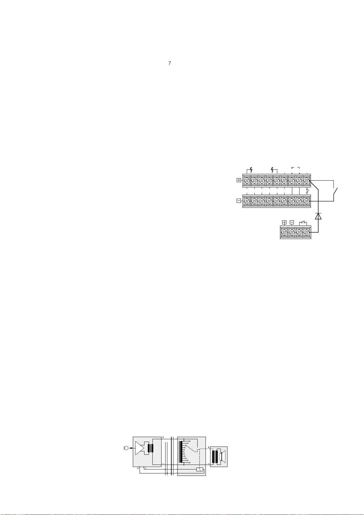
the storage M 6 of the PA-1120DMT can be
Switch Line
Audio Line
PA-4000PTT
called up via the zone paging microphone
(position ON) or not (position OFF, factory
setting). The storage M 6 can e. g. be used
for an alarm announcement which is only to
be activated via the terminals MESSAGE FIRST
PRIORITY (33).
10)
In the amplifier, set the jumper MS 2 to position PRI. Thus, the volume of an announcement from the insertion will not be attenuated
by a signal of the zone paging microphone.
6.4.2 Microphone connection and
basicsetting
1) Connect the jack OUTPUT (63) of the micro-
phone to the jack INPUT of the connection
module. A short connection cable is supplied
with the microphone. The cable length between amplifier and microphone must be
1000 m as a maximum.
A 2nd microphone may be connected via its
jack OUTPUT to the jack LINK of the module or
to the jack LINK (62) of the 1
st
microphone. For
the connection of a 3rd microphone, connect its
jack OUTPUT to the jack LINK of the 2nd microphone. As a maximum, three microphones
may be connected. The cable length between
two microphones must not exceed 100 m.
2)
When using several microphones of type
PA-1120RC, set the TALK switch (61) to position PRIORITY on the microphone or on the
microphones which are to take priority over
the others. On the other microphones, set the
switch to position SLAVE. Thus, an announcement from a microphone without priority can
be interrupted by a microphone with priority.
3) To obtain 2nd priority for the zone paging microphone or the zone paging microphones,
press the button on the connection module
(position PRIORITY). If the button is not pressed
(position SLAVE), 4th priority is adjusted.
4) If the digital message insertion PA-1120DMT
is used, select with the switch DIGITAL
MESSAGE (60) if stored announcements can
be called up via the zone paging microphone
(switch position ON) or if they are locked
(position OFF).
5) If the inputs on the amplifier do not suffice, a
line input signal can be fed via the jacks AUX
IN (64) [e. g. background music from a CD
player]. Adjust the output level for the microphone signal and the signal from the jacks
AUX IN with the control AUDIO OUT (65).
6.5 Units with line level /
audiorecorder
Up to five units with line level (e. g. CD players,
cassette recorders) may be connected to the inputs CH 1 to CH 3 (39) as well as CH 4 and
CH 5 (38). Exceptions: Do not use CH 1 when
operating the desk microphone PA-4000PTT or
PA-4300PTT and do not use CH 2 when operating the zone paging microphone PA-1120RC!
For background music, the inputs CH 4 and
CH 5 should be used because these have the
lowest priority.
1) When connecting the inputs CH 1 to CH 3,
turn the corresponding GAIN control (41)
fully to the left to position “−10”. Do not
press the corresponding button PHANTOM
POWER (40).
When connecting a stereo unit to one
of the inputs CH 1 to CH 3, use a stereo
mono adapter (e. g. SMC-1 from MONACOR)
and an adapter cable (e. g. MCA-300 from
MONACOR), otherwise the signals of the stereo centre cancel each other mutually.
2) If one of the inputs CH 1 to CH 3 is to take
priority over the other two inputs, set the corresponding DIP switch MIC PRIORITY (45) to
position ON. The inputs CH 1 to CH 3 always
take priority over the inputs CH 4 and CH 5
(also see chapter 7
).
3) An audio recorder may be connected to the
jacks REC (37). The recording volume is independent of the MASTER control (21) and the
zone attenuators (5).
6.6 Inserting the equalizer or
another unit
For external sound effects, e. g. an equalizer may
be inserted via the jacks AMP IN (35) and PRE
OUT (36): Connect the input of the unit to the
jack PRE OUT and the output to the jack AMP IN.
Note: A signal interruption occurs in the amplifier if
only jack AMP IN is connected or if the inserted unit is
not switched on, if it is defective, or if it is not correctly
connected. Then the speakers remain mute.
6.7 Additional amplifier
If more speakers are required than admissible
for the amplifier, another amplifier is necessary.
Connect the input of the additional amplifier to
the jack PRE OUT (36) or REC (37). The signal
for the additional amplifier is not affected by the
control MASTER (21) and by the zone volume
switches (5).
6.8 Telephone bell or night bell
If required, a telephone bell or night bell may
sound via the PA system (e. g. during a nightly
inspection round).
1) Feed the signal for the bell (e. g. 8 V/ 50 Hz) to
the terminals NIGHT RINGER (29).
2) Press the button TEL (14).
3) Trigger the bell, and adjust the volume of the
ringing tone generated by the amplifier with
the control RINGER (16).
4)
Switch on or off the ringing function with the
button TEL according to your requirements.
Note: The bell takes the lowest priority.
6.9 Emergency priority relays
If PA volume adjusting controls with emergency priority relays (e. g. series ATT-3..PEU or
ATT-5..PEU from MONACOR) are inserted between the amplifier and the speakers, important
announcements can also be heard with the volume “zero” adjusted.
1) For this purpose, connect a desk microphone
PA-4000PTT or PA-4300PTT (see chapter 6.3).
2)
Connect the emergency priority relays according to fig. 6 to the screw terminals PRIORITY
RELAY OUTPUT (42). The output allows a load
of 200 mA.
3)
Set the switch PRIORITY (48, 54) on the
microphone to position ON (downwards).
4) Upon actuation of the TALK button (52, 59),
the speakers are now switched to maximum
volume via the relays.
ATT-…PA-1120/PA-1240
100V
PRIORITY RELAY
OUTPUT
24 V, max. 0,2 A
PA-4300PTT
Emergency priority relays
➅
24 V
10
0
100 V
Speaker
6.10 Switch for (automatic)
announcements inallzones
For remote control of the following functions,
connect a switch to the terminals MESSAGE FIRST
PRIORITY (33).
1. All PA zones are switched on and set to maxi-
mum volume [like button ALL CALL (6)].
2. When the digital message insertion PA-
1120DMT is used, the announcement of
storage M6 is automatically called up. For
this purpose, set the jumper MS 2 to position
PRI prior to installing the insertion (see layout
diagram on page 48). Thus, the announcement of storage M 6 takes first priority.
Instead of the switch, an alarm contact may
be connected, e. g. for an automatic fire alarm
announcement.
3. If the amplifier is to be switched on simulta-
neously via the switch or the alarm contact,
insert a diode of type 1N4004 between the
upper terminal MESSAGE FIRST PRIORITY and
the right terminal POWER REMOTE according
to fig. 7.
TEL
SPEAKER ZONES
ATT- OUTPUTS
Z5 Z4 Z3 Z2 Z1 4Ω
Automatic switching on of the amplifier
➆
and activation of the announcement M 6
LOW
IMP
24V⎓/27A
NIGHT
RINGER
MESSAGE
FIRST
PAGING
PRIORITY
IN
POWER
MAX
REMOTE
1N4004
6.11 Telephone switchboard
From a telephone switchboard, announcements
may be reproduced via the PA system.
1)
Feed the telephone signal (line level) to the
terminals PAGING IN (32).
2) During an announcement, adjust the volume
with the control PAGING (15).
Note: Telephone announcements take 3rd priority.
6.12 Switching on / off by
remotecontrol
A separate switch allows to switch the amplifier
on and off by remote control.
1)
Connect the screw terminals POWER REMOTE
(31) via a two-pole cable to a single-pole
power switch.
2)
For switching on / off by remote control, the
main switch POWER (24) must not be pressed.
6.13 Power supply and emergency power supply
1)
For continuous operation of the amplifier
after power failure, connect a 24 V emergency power supply unit (e. g. PA-24ESP from
MONACOR) to the terminals 24 V⎓ (30). For a
cable length of up to 7 m, a cable cross-section
of 4 mm2 as a minimum is required.
2)
Finally connect the supplied mains cable to
the mains jack (27) first and then to a mains
socket (230 V/ 50 Hz).
Note: Even when the amplifier is switched off, it has
a low power consumption. Therefore, disconnect the
mains plug from the socket and, if necessary, disconnect
the emergency power supply unit if the amplifier will not
be in operation for a longer time.
English
13
Page 14

7 Defining the Priority of
InputSignals
A priority is assigned to all input signals. A signal
English
of higher priority always covers a signal of lower
priority if both signals are simultaneously applied
to the amplifier. (Signals of the same priority are
mixed.) The following table gives a survey and
shows possibilities of modification.
Priority Signal Condition Modification
announcement
M 6 from digital
1
message insertion
PA-1120DMT
desk microphone
PA-4000PTT
PA-4300PTT
zone paging
2
microphone
PA-6000RC
chime — —
telephone
switchboard at
3
terminal(32)
inputs CH 1,
CH2and CH 3
4
siren — —
completion
insertions
5
inputs 4 and 5 — —
telephone bell or
night bell
1. Factory setting
2. The desk microphone PA-4000PTT/ PA-4300PTT
uses input CH 1, and the zone paging microphone
PA-1120RC uses input CH 2. Via the corresponding
DIP switch MIC PRIORITY (45), the microphones can
also be set to 3rd priority.
jumper MS 2
to PRI
switch at (33)
closed
DIP switch
PRIORITY (48,
54) to ON
switch at connection module
to PRIORITY
— —
DIP switch (45)
1
to OFF
jumper MS 2 to
1
SLAVE
— —
switch to OFF
= 4
switch to
SLAVE =
th
priority
4
DIP switch
to ON =
rd
priority
3
jumper MS 2
to PRI =
nd
2
8 Operation
If the amplifier is switched off and the mains
voltage or emergency supply voltage is applied,
the LED STAND BY (25) lights up.
1)
Prior to switching on the amplifier for the first
time, set all five input controls LEVEL (8 and
10) and the MASTER control (21) to position
“0” for the time being.
2)
Switch on the amplifier with the POWER
switch (24). The LED STAND BY extinguishes,
and the LED AC (23) lights up. In case of power
failure and applied emergency power supply,
the LED DC lights up instead of the LED AC.
8.1 Adjusting the volume
1) First adjust the desired maximum volume for
announcements of highest priority. For this
purpose, press the button ALL CALL (6) first.
Make the announcement according to the
equipment used:
a) In case of a digital message insertion, call
up the announcement from the storage
M6 via a switch at the terminals MESSAGE
FIRST PRIORITY (33). Set the LEVEL control on the insertion to position 7 approximately.
b) In case of a desk microphone PA-4000PTT
or PA-4300PTT, set the corresponding
LEVEL control (8) of the input CH 1 to position 7 approximately, and make an announcement.
th
priority
priority
c) In case of a zone paging microphone PA-
1120RC, set the corresponding LEVEL control (8) of the input CH 2 to position 7 approximately, and make an announcement.
d) When a different microphone is used, set
the corresponding LEVEL control (8) to position 7 approximately, and make an announcement.
2)
During the announcement, adjust the volume
with the MASTER control (21). In case of overload, the red LED CLIP of the level indicators
(7) lights up. In this case, reduce the volume
with the MASTER control.
3) To adjust the volume for normal announce-
2
ments, unlock the button ALL CALL again.
For this purpose, press all buttons (4) of the
individual PA zones.
2
4) Make an announcement as described under
step 1) b or d.
Notes:
On PA-4000PTT / PA-4300PTT, set the switch PRIORITY (48, 54) to the upper position.
Do not make the announcement via a PA-1120RC;
its volume is independent of the zone volume
switches(5).
5) Do not change the MASTER control (21), but
adjust the desired volume for each zone separately with the corresponding zone attenuators (5) during the announcement.
6) Then adjust the volume for the signals of the
other inputs (e. g. background music) with the
corresponding LEVEL control (8 or 10).
7)
Adjust the sound for each input used with
the corresponding controls BASS and TREBLE
(9 and 11). Adjust the sound for an insertion
module in the compartment (1) with the controls PACK (2 and 3).
8)
It may be necessary to readjust the volume
of the input signals with the corresponding
controls (8 or 10).
9)
Set the inputs which are not used to ”0” with
the corresponding controls.
Note: For the inputs CH 1 to CH 3, the input sensitivity
can be adjusted with the controls GAIN (41). If a level
control (8) must be turned up very much or almost be
closed to obtain the desired volume ratio to the other
inputs, modify the input sensitivity with the corresponding control GAIN.
8.2 Activating the PA zones
1) Switch on the zones to be activated with the
buttons
the activated zones.
2)
For announcements to all zones, press the
button ALL CALL (6). At the same time, the
volume of the zones is increased to maximum
[corresponds to the adjustment of all zone
attenuators (5) to position 6].
Z 1 – Z 5 (4). The green LEDs indicate
8.4 Alarm siren
In case of an alarm, one of the two sirens on
the operating panel SIREN can be switched on:
Button “~” (17) for a wailing tone
Button “–” (19) for a steady tone
Adjust the volume of the alarm tone with the
LEVEL control (18).
8.5 Desk microphone PA-4000PTT or PA-4300PTT
1)
With the microphone PA-4000PT or PA4300PTT connected, the input CH 1 is no
longer available. As the microphone requires
phantom power for operation, press the
switch PHANTOM POWER (40) of input CH 1.
2)
If the chime is to sound prior to an announcement when the TALK button (52, 59)
is pressed, set the switch CHIME (47, 53) on
the rear side of the microphone to position
ON (downwards).
3) Set the switch PRIORITY (48, 54) to position
ON
1. if the microphone is to take 2nd priority,
2. if all PA zones are to be switched on and to
be set to maximum volume when the TALK
button is pressed [like button ALL CALL (6)],
3. if the emergency priority relays are to respond (see chapter
6.9).
4) For an announcement, keep the TALK button
(52, 59) pressed and wait for the chime, if
required. The green LED lights up as long as
the TALK button is pressed.
5)
When two or three microphones PA-4300PTT
are connected, the switch MASTER / SLAVE (55)
can be used to define different priorities for
the microphones:
SLAVE other microphones set to MASTER
will take priority
MASTER the microphone will take priority over
microphones set to SLAVE
The red LED BUSY above the TALK button
lights up when another PA-4300PTT with the
switch MASTER / SLAVE set to the position
MASTER is used for making announcements.
8.6 Zone paging microphone
PA-1120RC
1) With the buttons SPEAKER ZONES SELECTOR
(70), first switch on the PA zones in which the
announcement is to be heard, otherwise no
announcement will be possible. To activate all
zones, press the button ALL CALL (71).
2) For the announcement, keep the TALK button (68) pressed. The amplifier activates the
PA zones according to the preselection under
item 1) independent of the adjustments at
the amplifier and increases the volume in the
8.3 Chime
When the TALK button (52, 59, 68) on the microphone PA-4000PTT, PA-4300PTT or PA-1120RC
is actuated, a chime will precede an announcement. When using other microphones, the chime
can also be triggered with the button CHIME
(12). Adjust the volume of the chime with the
LEVEL control (13).
With the jumper MS 1, it is possible to switch
between a 2-tone chime and a 4-tone chime,
see chapter 5.
zones to maximum [corresponds to the adjustment of all zone volume switches (5) to
position 6]. After the chime, make the announcement.
3)
When using the digital message insertion
PA-1120DMT, a stored announcement may
also be called up via the zone paging microphone if the switch DIGITAL MESSAGE (60) is
set to position ON:
a) Select the stored announcement with the
selector switch MESSAGE BANK (69).
14
Page 15

b)
Start the announcement with the button
START/ STOP (73). To stop the announcement, press the button START/ STOP again.
c) With the button REPEAT/ STOP (72), an an-
nouncement can also be repeated several
times. Adjust the number of repeats and the
intervals on the insertion (see instructions of
this insertion). To stop the announcement,
actuate the button REPEAT/ STOP again.
Notes:
1. The announcement of storage M 6 may be locked
(see chapter 6.4.1, item 9). If the switch MESSAGE
BANK is set to position 6 in this case, the announcement selected before is reproduced.
2. If at least one zone button (4) is pressed at the
amplifier, after releasing the TALK button, the
announcement selected with the switch MESSAGE
BANK can be heard. To prevent this, leave a storage location of the digital message insertion open
or cancel it and select this storage location with
the switch MESSAGE BANK.
4) The three LEDs POWER, SEND and BUSY (67)
give the following information:
POWER lights up when the amplifier is
switched on
SEND lights up when an announcement is
made via the microphone or a stored
announcement is called up
BUSY lights up with individual announce-
ments and with announcements
via other connected microphones
PA-1120RC.
9 Protective Circuit
The amplifier is provided with a protective circuit
against overload and overheating. If the protective circuit is activated, the LED PROT (22) lights
up and the amplifier is muted:
1. for approx. 1 second after switching on
(switch-on delay)
2. for approx. 1 second after switching off
3. if the amplifier is overloaded
4. if the amplifier is overheated; in addition, the
LED TEMP (20) lights up
If the LED PROT lights up during operation or if
it does not extinguish after switching on, switch
off the amplifier and eliminate the source of error.
10 Specifications
Model PA-1120 PA-1240
Output power
Rated power
100 V outputs*
4 Ω outputs*
Max. output power
THD < 1 % < 1 %
Inputs
MIC / LINE CH 1 – CH 3
LINE CH 4 and CH 5
AMP IN
TEL PAGING
Extension insertion
Phantom power 17 V for CH 1 – 3, to be switched individually
Outputs
Speakers*
REC
PRE OUT
Frequency range 55 – 16 000 Hz, −3 dB
Equalizer
Bass
Treble
S / N ratio
Line
Mic
Ambient temperature 0 – 40 °C
Power supply
Mains voltage
Power consumption
Emergency power supply:
Direct current consumption
Dimensions (W × H × D)
Rack spaces
Weight 13 kg 14 kg
* Either use the 100 V outputs
or the 4 Ω output! Subject to technical modification.
5 × 100 W, however together
not more than 120 W
482 × 133 × 352 mm
1 × 120 W
170 W
Input sensitivity, impedance; connection
2.5 – 300 mV, 5 kΩ; XLR / 6.3 mm jack, bal.
300 mV, 15 kΩ; RCA, unbal.
775 mV, 10 kΩ; 6.3 mm jack, unbal.
250 mV, 5 kΩ; screw connection, bal.
250 mV, 10 kΩ, unbal.
5 × 100 V, 1 × 4 Ω
775 mV at 3 kΩ, unbal.
775 mV at 100 Ω, unbal.
±10 dB / 100 Hz
±10 dB / 10 kHz
> 80 dB (A weighted)
> 70 dB (A weighted)
230 V/ 50 Hz
340 VA
⎓ 24 V
15 A
3 RS
5 × 100 W, however together
not more than 240 W
1 × 240 W
340 W
230 V/ 50 Hz
630 VA
⎓ 24 V
27 A
482 × 133 × 352 mm
3 RS
English
All rights reserved by MONACOR ® INTERNATIONAL GmbH & Co. KG. No part of this instruction manual
may be reproduced in any form or by any means for any commercial use.
15
Page 16

Amplificateur-Mixeur 5 zones
Public Adress
Cette notice s’adresse aux installateurs d’instal-
Français
lations de sonorisation (chapitres 1 – 10) et aux
utilisateurs sans connaissances techniques particulières (chapitres 1 – 3, 8). Veuillez lire la présente
notice avec attention avant le fonctionnement
et conservez-la pour pouvoir vous y reporter
ultérieurement.
Vous trouverez sur la page 3, dépliable, les
éléments et branchements décrits.
Table des matières
1 Vue d’ensemble . . . . . . . . . . .
1.1 Amplificateur – Face avant . . . . . . . .
1.2 Amplificateur – Face arrière. . . . . . . .
1.3 Microphone de table PA-4000PTT (accessoire)
1.4 Microphone de table PA-4300PTT (accessoire)
1.5 Micro de commande PA-1120RC (accessoire)
2 Conseils de sécurité et d’utilisation . .
3 Possibilités d’utilisation et accessoires .
4 Installation de l’amplificateur . . . . .
4.1 Installation en rack . . . . . . . . . . .
5 Réglage de la sonorité du gong et de la
priorité du module inséré . . . . . . .
6 Branchements . . . . . . . . . . . .
6.1 Haut-parleurs . . . . . . . . . . . . .
6.2 Microphones . . . . . . . . . . . . .
6.3 Microphone de table PA-4000PTT
ou PA-4300PTT
6.4 Micro de commande PA-1120RC. . . . . .
6.4.1 Installation du module de branchement . .
6.4.2 Branchement du micro et réglagedebase .
6.5 Appareils avec niveau Ligne / enregistreur . .
6.6 Insertion d’un égaliseur ou d’un autre appareil
6.7 Amplificateur supplémentaire . . . . . . .
6.8 Sonnerie de téléphone ou sonnette de nuit. .
6.9 Relais d’annonce forcée . . . . . . . . .
6.10 Interrupteur pour annonces (automatiques) dans toutes les zones
6.11 Centrale téléphonique . . . . . . . . . .
6.12 Interrupteur pour un marche / arrêt à distance
6.13 Alimentation secteur et desecours . . . . .
7 Déterminer la priorité
des signaux d’entrée
8 Fonctionnement . . . . . . . . . . .
8.1 Réglage de volume . . . . . . . . . . .
8.2 Activation des zones de sonorisation . . . .
8.3 Gong . . . . . . . . . . . . . . . .
8.4 Sirène d’alarme . . . . . . . . . . . .
8.5 Microphone de table PA-4000PTT
ou PA-4300PTT
8.6 Micro commande PA-1120RC . . . . . . .
9 Circuit de protection . . . . . . . . .
10 Caractéristiques techniques . . . . . .
Plan de branchement . . . . . . . . . . . . . . . . 48
. . . . . . . . . . . . . . . . . . . . . . . 49
Schéma
. . . . . . . . . . . .
. . . . . .
. . . . . . . . .
. . . . . . . . . . . .
1 Vue d’ensemble
1.1 Amplificateur – Face avant
1 Couvercle du compartiment insert :
possibilité d’insérer un module MONACOR,
par exemple, tuner, lecteur CD, insert de messages digitaux.
2
Réglage des aigus TREBLE pour un appareil
inséré dans le compartiment(1)
3
Réglage des graves BASS pour un appareil
inséré dans le compartiment (1)
4 Touches avec LEDs de contrôle pour allumer
les zones de sonorisation individuelles Z1 à
16
16
16
17
17
17
17
18
18
18
18
18
18
18
18
18
18
19
19
19
19
19
19
19
19
19
20
20
20
20
20
20
20
20
21
21
21
Z5
5
Potentiomètres atténuateurs de zones pour
un réglage distinct du volume dans chaque
zone
6 Touche ALL CALL avec LED de contrôle pour
allumer toutes les zones simultanément et
augmenter le volume respectivement au
maximum [indépendant des touches (4) et
des atténuateurs de zones (5)] ; le volume
maximal est limité seulement par le réglage
MASTER (21).
7 VU-mètre à LEDs pour l’amplificateur [indé-
pendant des atténuateurs de zones (5)] :
en cas de surcharge, la LED CLIP rouge brille.
8 Réglages pour les entrées CH 1 à CH 3 (39):
avec le potentiomètre CH 1, le niveau est
réglé pour un micro branché à la prise (43)
ou (44) et avec le potentiomètre CH 2, le
niveau du microphone de commande de type
PA-1120RC (branché via un module séparé) :
la priorité de ces entrées est réglable via les
interrupteurs DIP (45).
9 Réglages graves / aigus pour les entrées CH1
à CH3 (39)
10
Réglage de niveau pour les entrées Ligne CH4
et CH5 (38)
11
Réglages graves / aigus pour les entrées CH
4 et CH 5
12
Touche gong : le gong a la priorité 2 (Pour
commuter entre gong 2 sons et gong 4 sons,
voir chap. 5)
13 Réglage de volume du gong
14
Touche TEL : si la touche est enfoncée, on peut
entendre, sur tous les haut-parleurs, p. ex. une
sonnerie de téléphone ou sonnette de nuit
[branchement via les bornes NIGHT RINGER
(29)] ; la sonnerie a la priorité la plus faible.
15
Réglage de volume pour le si gnal téléphonique amené via les bornes PAGING IN (32) :
ce signal a priorité 3.
16 Réglage de volume pour la sonnerie de télé-
phone ou une sonnette de nuit (voir également position 14 et 29)
17
Touche pour un son de sirène ondulant, la
sirène a la priorité 4
18 Réglage de volume de la sirène
19 Touche pour un son de sirène continu
20 LED TEMP de surchauffe :
brille lorsque le système de refroidissement
atteint une température de 100 °C. Toutes les
sorties haut-parleurs sont muettes ; en plus,
la LED PROT (22) rouge brille.
21 Réglage MASTER pour le volume général
22 LED PROT : brille lorsque le circuit de protec-
tion est activé :
1. pendant 1 seconde environ après la mise
sous tension (temporisation d’allumage)
2. pendant 1 seconde environ après l’arrêt
3. en cas de surcharge de l’amplificateur
4. en cas de surchauffe de l’amplificateur
23 LEDs, témoin de fonctionnement :
DC brille lorsque l’amplificateur fonctionne
avec une alimentation de secours 24 V
en cas de coupure de courant
AC brille lorsque l’amplificateur est relié à
une tension secteur
24 Interrupteur POWER Marche /Arrêt
25 Touche STAND BY : brille lorsque l’amplifica-
teur est éteint
1.2 Amplificateur – Face arrière
26 Bornes haut-parleurs pour des haut-parleurs
100 V
Attention ! Chacune des cinq sorties de
zone peut recevoir une charge de 100 W
RMS au maximum par les haut-parleurs.
En aucun cas la charge totale admissible ne
doit être dépassée :
PA-1120 120 W RMS
PA-1240 240 W RMS
27 Prise pour le cordon secteur livré pour bran-
cher à 230 V/ 50 Hz.
28
Sortie haut-parleur 4 Ω pour un groupe de
haut-parleurs avec une impédance totale de
4 Ω au moins
Attention ! cette sortie ne doit être utilisée
que lorsque les sorties 100 V (26) ne sont pas
utilisées. Sinon, il y a surcharge de l’amplificateur.
29
Entrée pour la tension de sonnerie (par
exemple 8 V/ 50 Hz) d’une sonnerie de téléphone ou de nuit : la tension de sonnerie
déclenche un signal d’appel que l’on peut
écouter via les haut-parleurs (voir également
position 14 et 16)
30
Bornier pour une alimentation de secours
(⎓24 V)
31
Bornier pour brancher un interrupteur externe
pour un démarrage / arrêt à distance [l’interrupteur POWER (24) ne doit pas être enfoncé].
32 Entrée (symétrique, 250 mV), pour un signal
téléphonique devant être écouté via l’installation PA (voir également position 15)
33
Bornier pour brancher un interrupteur distinct :
il est ainsi possible d’appeler une annonce
d’alarme mémorisée lorsque l’insert de messages digitaux PA-1120DMT est installé. Simultanément, toutes les zones de sonorisation
sont allumées, et réglées sur le volume maximal [comme avec la touche ALL CALL (6)].
34 Plaque cache : est remplacée par une plaque
de branchement si le module PA-1120DMT,
PA-1140RCD, PA1200C ou PA-1200RDSU est
inséré
35
Entrée AMP IN en liaison avec la sortie PRE
OUT (36) pour insérer par exemple, un égaliseur. Seul le signal appliqué ici est reproduit;
l’amplificateur de puissance est séparé du
préamplificateur.
36
Sortie PRE OUT pour brancher un amplificateur supplémentaire (chapitre 6.7) ou en
liaison avec l’entrée AMP IN (35) pour insérer
par exemple un égaliseur.
Le volume de la sortie est indépendant du
réglage MASTER (21).
37 Sortie REC : branchement d’un enregistreur;
le volume de sortie est indépendant du réglage MASTER (21)
38 Entrées CH 4 et CH 5 pour appareils à niveau
Ligne (p. ex., lecteur CD, magnétophone...);
16
Page 17

les deux canaux stéréo L et R sont mixés en
interne vers un signal mono
39 Entrées symétriques CH 1 à CH 3 via prises
XLR / jack 6,35 (combo) ;
la sensibilité d’entrée se règle avec les réglages
GAIN (41) entre le niveau micro et le niveau
Ligne (2,5 – 250 mV)
40
Interrupteur PHANTOM POWER pour allumer
l’alimentation 17 V pour des microphones à
alimentation fantôme ; respectivement pour
les entrées CH 1 à CH 3
Attention ! Si l’alimentation 17 V est allumée,
il ne faut pas brancher de micro à sortie asymétrique à la prise d’entrée correspondante
(39), le microphone peut être endommagé.
41
Réglage de la sensibilité d’entrée pour chacune
des entrées CH 1 à CH 3 (voir position39)
42
Bornes à vis pour brancher des relais d’annonce forcée, voir chapitre 6.9
43 Prise PA-4000PTT : branchement d’un micro
de table PA de type PA-4000PTT
44 Prise PA-4300PTT : branchement d’un micro
de table PA de type PA-4300PTT
45 Interrupteurs DIP MIC PRIORITY : en position
ON, l’entrée correspondante (CH 1, CH 2 ou
CH 3) passe de priorité 4 à priorité 3
46 Cache : le module de connexion, s’il y a uti-
lisation du micro de commande PA-1120RC,
se monte ici.
1.3 Microphone de table PA-4000PTT
(accessoire)
Important ! pour le fonctionnement du micro,
reportez-vous au chapitre 6.3.
47 Interrupteur DIP CHIME ;
en position ON, le gong émet un signal sonore lorsqu’on enfonce la touche de parole
TALK (52)
48 Interrupteur DIP PRIORITY :
OFF : le micro a priorité 4
ON : le micro a priorité 2 :
lorsqu’on enfonce la touche TALK, toutes les
zones sont allumées et leur volume est réglé
de manière maximale [comme avec la touche
ALL CALL (6)] ; aux bornes PRIORITY RELAY
OUTPUT (42), une tension de 24 V / 0,2 A max.
est présente pour commuter des relais d’annonce forcée (voir chap. 6.9).
49
Prise RJ 45 pour brancher à la prise PA4000PTT (43) de l’amplificateur
50
Prise DIN 7 pôles pour brancher à un autre
amplificateur avec prise correspondante
51 Capsule micro avec bonnette anti-vent
52
Touche TALK ; lorsque la touche est enfoncée,
la LED verte au-dessus brille
1.4 Microphone de table PA-4300PTT
(accessoire)
Important ! pour le fonctionnement du micro,
reportez-vous au chapitre 6.3.
53 Interrupteur DIP CHIME ;
en position ON, le gong émet un signal sonore lorsqu’on enfonce la touche de parole
TALK (59)
54 Interrupteur DIP PRIORITY :
OFF : le micro a priorité 4
ON : le micro a priorité 2 :
lorsqu’on enfonce la touche TALK, toutes les
zones sont allumées et leur volume est réglé
de manière maximale [comme avec la touche
ALL CALL (6)] ; aux bornes PRIORITY RELAY
OUTPUT (42), une tension de 24 V / 0,2 A max.
est présente pour commuter des relais d’annonce forcée (voir chap. 6.9).
55
Interrupteur MASTER / SLAVE : définition de la
priorité lorsqu’on branche d’autres micros de
type PA-4300PTT
SLAVE les autres micros branchés sur MAS-
TER ont la priorité
MASTER le microphone a priorité sur les
microphones commutés sur SLAVE
56 Prise RJ 45 OUTPUT pour brancher à la prise
PA-4300PTT (44) de l’amplificateur
57
Prise RJ 45 LINK pour brancher un autre micro
PA-4300PTT
(on peut brancher, au plus, 3 micros reliés
ensemble à l’amplificateur)
58 Capsule micro avec bonnette anti-vent
59
Touche TALK ; lorsque la touche est enfoncée,
la LED verte TALK au-dessus brille
La LED rouge BUSY brille si quelqu’un parle
depuis un autre PA-4300PTT dont l’interrupteur MASTER / SLAVE est sur la position
MASTER.
1.5 Micro de commande PA-1120RC
(accessoire)
Pour faire fonctionner le PA-1120RC, le module
de connexion fourni avec le micro doit être installé (voir chapitre 6.4.1).
60 Interrupteur DIGITAL MESSAGE : en position
ON, appel des messages memorisés*
61
Interrupteur TALK : définition de la priorité
lorsqu’on branche d’autres micros de type
PA-1120RC
SLAVE les autres micros branchés sur PRIO-
RITY ont la priorité
PRIORITY le microphone a priorité sur les
microphones commutés sur SLAVE
62 Prise LINK pour brancher d’autres micros de
commande de type PA-1120RC
63 Prise OUTPUT pour relier à la prise INPUT du
module de branchement livré avec le microphone
64 Prises d’entrée AUX IN : signal audio supplé-
mentaire à niveau Ligne
65
Réglage de niveau de sortie pour le signal
micro et le signal aux prises AUX IN (55)
66 Capsule micro avec bonnette anti-vent
67 LEDs de contrôle :
POWER témoin de fonctionnement
(amplificateur allumé)
SEND brille lorsqu’une annonce est faite
via le micro ou si un message mémorisé* est appelé
BUSY brille pour des annonces person-
nelles ou pour des annonces via
d’autres microphones PA-1120RC
reliés
68 Touche TALK : parole
69
Commutateur rotatif pour sélectionner un
message mémorisé*
70
Touches zones Z 1 à Z 5 avec LEDs de contrôle
pour activer les zones dans lesquelles l’annonce doit être entendue.
71
Touche ALL CALL avec LED de contrôle :
pour allumer toutes les zones simultanément
[comme la touche (6)].
72
Touche REPEAT/ STOP : lecture répétée d’un
message mémorisé* ; une nouvelle pression
ar rête le message.
73
Touche START/ STOP : lecture d’un message
memorisé* : une nouvelle pression arrête le
mes sage.
2 Conseils de sécurité et
d’utilisation
L’appareil répond à toutes les directives nécessaires de l’Union Européenne et porte donc le
symbole .
AVERTISSEMENT
Pendant le fonctionnement, une tension dangereuse jusqu’à 100 V est présente aux bornes
haut-parleurs (26). Tout branchement ne peut
être effectué ou modifié que si l’appareil est
éteint.
Même éteint, cet appareil n’est pas entière-
•
ment coupé de la tension secteur, il a une faible
consommation.
L’appareil n’est conçu que pour une utilisation
•
en intérieur. Protégez-le des éclaboussures, de
tout type de projections d’eau, d’une humidité
d’air élevée et de la chaleur (température ambiante ad missible 0 – 40 °C).
En aucun cas, vous ne devez pas poser d’objet
•
contenant du liquide ou un verre sur l’appareil.
La chaleur dégagée par l’appareil doit être
•
évacuée par une circulation d’air correcte.
N’obstruez pas les ouïes de ventilation.
Ne faites pas fonctionner l’appareil et débran-
•
chez le cordon secteur immédiatement dans
les cas suivants :
1.
l’appareil ou le cordon secteur présentent
des dommages visibles.
2. après une chute ou accident similaire, vous
avez un doute sur l’état de l’appareil.
3. des dysfonctionnements apparaissent.
Dans tous les cas, les dommages doivent être
réparés par un technicien spécialisé.
Ne débranchez jamais l’appareil en tirant sur
•
le cordon secteur ; retirez toujours le cordon
secteur en tirant la fiche.
Pour le nettoyage, utilisez un chiffon sec et
•
doux, en aucun cas de produits chimiques ou
d’eau.
Nous déclinons toute responsabilité en cas de
•
dommages corporels ou matériels résultants si
l’appareil est utilisé dans un but autre que celui
pour lequel il a été conçu, s’il n’est pas correctement branché ou utilisé ou s’il n’est pas
réparé par une personne habilitée ; en outre,
la garantie deviendrait caduque.
L’appareil est alimenté par une
tension dangereuse. Ne touchez jamais l’intérieur de l’appareil et ne faites rien tomber
dans les ouïes de ventilation
car, en cas de mauvaise manipulation, vous pouvez subir
une décharge électrique.
Lorsque l’appareil est définitivement
retiré du service, vous devez le déposer
dans une usine de recyclage de proximité pour contribuer à son élimination
non polluante.
Français
* fonction uniquement si le module de messages digitaux
PA-1120DMT est installé
CARTONS ET EMBALLAGE
PAPIER À TRIER
17
Page 18

3 Possibilités d’utilisation et
accessoires
Cet amplificateur est spécialement conçu pour
Français
une installation dans des systèmes de sonorisation Public Adress 100 V ; il dispose de sorties
Ligne 100 V pour 5 zones de sonorisation au plus
dont le volume est réglable individuellement. Il
est possible de brancher des microphones ou
appareils à niveau Ligne via les trois entrées avec
priorité réglable individuellement. Deux autres
entrées Ligne avec priorité plus inférieure complètent les possibilités de branchement.
Accessoires
Modules d’insert pour le compartiment d’extension (1)
PA-1120DMT
PA-1140RCD
PA-1200C programmateur
PA-1200RDSU
Microphones Public Adress spécialement conçus
PA-4000PTT
(schéma 3)
PA-4300PTT
(schéma 4)
PA-1120RC
(schéma 5)
mémoire de messages digitaux avec
programmateur
radio / lecteur CD
radio AM / FM avec lecteur audio
pour cet amplificateur
Vous pouvez brancher un micro de
table à la prise PA-4000PTT (43).
On peut relier un microphone de
table à la prise PA-4300PTT (44).
Trois PA-4300PTT en tout peuvent
fonctionner avec l’amplificateur.
On peut connecter trois microphones
commande ; un module de branchement, placé dans l’amplificateur, est
livré avec le microphone.
4 Installation de
l’amplificateur
L’amplificateur est prévu pour une installation
en rack 19” (482 mm) mais peut également être
posé directement sur une table. Dans tous les
cas, veillez à assurer une circulation d’air suffisante via les ouïes de ventilation pour garantir
un refroidissement suffisant de l’amplificateur.
4.1 Installation en rack
Pour un montage en rack 3 unités (= 133 mm)
sont nécessaires. Pour éviter toute chute, l’amplificateur doit être placé dans la partie inférieure
du rack ; le panneau avant ne suffit pas pour une
fixation sûre ; l’amplificateur doit être supporté
par des rails latéraux ou une plaque de base.
L’air chaud soufflé latéralement par l’amplificateur doit pouvoir être évacué du rack. Sinon, il
y a accumulation de chaleur dans le rack ce qui
peut endommager non seulement l’amplificateur
mais aussi les autres appareils placés dans le rack.
Insérez une unité de ventilation dans le rack en
cas de dégagement insuffisant de chaleur (p. ex.
DPVEN-04).
5 Réglage de la sonorité du
gong et de la priorité du
module inséré
Avant d’insérer le module dans le compartiment (1), réglez les deux cavaliers MS 1 (gong)
et MS2 (priorité du module), voir diagramme
page 48. Une fois le module placé, ils sont
inaccessibles.
1) Débranchez l’amplificateur du secteur et de
l’alimentation de secours.
2) Dévissez le cache (1) pour le module.
3) Réglez la sonorité du gong avec le cavalier
MS 1 :
position «4 Tone» : gong 4 sons
position «2 Tone» : gong 2 sons
4)
Réglez la priorité pour le module insert
avec le cavalier MS 2 :
Position «SLAVE» (réglage usine) :
le signal du module a la priorité la plus faible.
Position «PRI» :
le signal du module a la priorité 2. Ce réglage
doit par exemple être sélectionné lorsque des
annonces mémorisées via le micro de commande PA-1120RC doivent être appelées
depuis le module de messages digitaux PA1120DMT.
Le chapitre 7 «Déterminer la priorité des signaux d’entrée» décrit toutes les priorités
pos sibles.
5)
Si aucun module n’est inséré, revissez le
cache(1).
6 Branchements
Seul un personnel qualifié peut effectuer les branchements et uniquement lorsque l’amplificateur
est éteint.
6.1 Haut-parleurs
Reliez soit des haut-parleurs 100 V pour les
cinq zones de sonorisation aux bornes SPEAKER
ZONES ATT. OUTPUTS (26)
Attention ! Chacune des cinq sorties de zone
peut recevoir une charge de 100 W RMS au
maximum par les haut-parleurs. En aucun cas la
charge totale admissible ne doit être dépassée :
PA-1120 120 W RMS
PA-1240 240 W RMS
soit reliez un groupe de haut-parleurs avec une
impédance totale de 4 Ω au moins aux bornes
LOW IMP 4 Ω (28). Les réglages de volume de
zones (5) n’influent pas sur cette sortie. N’utilisez
en aucun cas les sorties 100 V (26) et la sortie 4 Ω
(28) simultanément sinon l’amplificateur serait
en surcharge.
Lorsque vous branchez les haut-parleurs, veillez toujours à respecter la polarité, c’est-à-dire reliez le branchement plus des haut-parleurs respec
tivement à la borne supérieure. Le branchement
plus des câbles haut-parleur est toujours repéré.
6.2 Microphones
Il est possible de relier trois microphones avec
fiche XLR ou jack 6,35 aux prises combinées XLR /
jack (39) des entrées CH1 à 3.
1)
Lors du branchement d’un microphone, tournez le réglage GAIN (41) correspondant entièrement à droite sur la position «−50».
2) Si vous utilisez un microphone à alimentation
fantôme, allumez l’alimentation 17 V avec la
touche PHANTOM POWER (40) correspondante.
Précaution ! N’activez l’interrupteur que
lorsque l’amplificateur est éteint (bruits de
commutation). Lorsque la touche est enfoncée, aucun microphone à sortie asymétrique
ne doit être branché à l’entrée correspondante
sinon il peut être endommagé.
3)
Si un microphone doit être prioritaire par rapport à un autre microphone, réglez l’interrupteur DIP MIC PRIORITY correspondant (45) sur
la position ON (voir également chapitre 7).
Remarques :
1. Si le microphone de table PA-4000PTT (schéma 3) ou
PA-4300PTT (schéma 4) est utilisé, il ne faut pas utiliser
l’entrée CH 1 car elle est branchée en parallèle avec
l’entrée (43) pour le PA-4000PTT et avec l’entrée (44)
pour le PA-4300PTT.
2. Si un microphone commande PA-1120RC est
relié, l’entrée CH 2 ne doit pas être utilisée
car elle est en parallèle avec l’entrée pour le
PA-1120RC (via le module de branchement
cor respondant).
6.3 Microphone de table PA-4000PTT
ou PA-4300PTT
Les microphones de tables, disponibles séparément, PA-4000PTT (schéma 3) et PA-4300PTT
(schéma 4) sont spécifiquement conçus pour cet
amplificateur.
1)
Reliez le microphone PA-4000PTT via sa
prise RJ 45 PTT REMOTE (49) à la prise PA4000PTT (43) sur l’amplificateur ou le micro
PA-4300PTT via sa prise OUTPUT (56) à la prise
PA-4300PTT (44) de l’amplificateur.
2) Il est possible de relier encore deux micros du
modèle PA-4300PTT : reliez la prise LINK (57)
du premier micro à la prise OUTPUT (56) du
deuxième micro et reliez le troisième micro au
deuxième de la même manière.
3)
Appuyez sur la touche PHANTOM POWER (40)
de l’entrée CH 1 et tournez le réglage correspondant GAIN (41) entièrement à droite sur
la position «−50».
Conseils:
1. L’entrée CH 1 ne doit pas être utilisée pour d’autres
signaux d’entrée car elle est branchée en parallèle avec
les prises pour les microphones de table.
2. La longueur totale maximale du cordon micro est
de 1000 m.
6.4 Micro de commande PA-1120RC
Le micro de table disponible en option (schéma5)
est spécialement conçu pour cet amplificateur;
il est possible de brancher jusqu’à 3 micros de
commande. Pour fonctionner, le module de branchement fourni avec le micro doit être placé en
premier dans l’amplificateur ; seul un personnel
qualifié peut effectuer les branchements.
Remarque : L’entrée CH 2 ne doit pas être utilisée pour
d’autres signaux d’entrée si le microphone de commande
est utilisé car elle est branchée en parallèle avec l’entrée
-
pour le micro de commande.
6.4.1 Installation du module de
branchement
1)
Débranchez la fiche secteur du secteur. Si une
unité d’alimentation de secours est branchée,
débranchez-la des prises 24 V⎓ (30) pour que
l’amplificateur soit dans tous les cas hors fonction. Dévissez le couvercle du boîtier de l’amplificateur et le cache (46) sur la face arrière
de l’amplificateur.
2) Placez le câble 3 pôles AS 903 C du module
de branchement dans la prise CN 903 C de
l’amplificateur – voir plan page 48.
3) Insérez le module dans l’espace libéré par le
cache (46) et vissez.
4) Reliez le câble deux pôles libre A dans l’am-
plificateur à un conducteur noir et rouge du
branchement AS 801 dans la prise CN 801 A
du module.
5) Reliez le câble blindé AS 802 B du module à
la prise AN 802 B de l’amplificateur.
6) Reliez le câble 6 pôles AS 204 D du module à
la prise CN 901 D de l’amplificateur.
7)
Si aucun module de messages digitaux PA1120DMT n’est inséré, fixez le câble 10 pôles
libre AS 4-1 du module avec des serre-câbles
dans l’amplificateur.
18
Page 19

Les points 8) à 10) ne concernent que l’utilisation
Switch Line
Audio Line
PA-4000PTT
TEL
du module de messages digitaux PA-1120DMT :
8) Reliez le cordon 10 pôles AS 4-1 du module
de branchement à la prise CN 4-1 du module
d’in sert.
9) Avec le cavalier MS 802 du module de branchement, déterminez si l’annonce dans la
mémoire M 6 du PA-1120DMT doit être appelée via le micro de commande (position
ON) ou pas (position OFF, réglage d’usine).
La mémoire M 6 peut par exemple être utilisée
pour une annonce d’alarme qui ne doit être
activée que via les bornes MESSAGE FIRST
PRIORITY (33).
10)
Dans l’amplificateur, mettez le cavalier MS 2
sur la position PRI. Ainsi le volume d’une
annonce venant du module d’insert n’est
pas diminué par un signal du microphone de
commande.
6.4.2 Branchement du micro et
réglagedebase
1)
Reliez la prise OUTPUT (63) du microphone
avec la prise INPUT du module de branchement. Un cordon court est livré avec le microphone. La longueur du câble entre l’amplificateur et le microphone ne doit pas être
supérieure à 1000 m.
Un second microphone peut, via sa prise
OUTPUT être relié à la prise LINK du module
ou à la prise LINK (62) du premier microphone.
Pour brancher un troisième microphone, reliez
sa prise OUTPUT à la prise LINK du deuxième
microphone. On peut relier au plus trois microphones. La longueur de câble entre deux
microphones ne doit pas dépasser 100 m.
2)
Si vous utilisez plusieurs micros de type
PA-1120RC, mettez l’interrupteur TALK (61)
sur la position PRIORITY du micro ou des micros qui doivent être prioritaires sur les autres.
Pour les micros restants, mettez l’interrupteur
sur SLAVE. Ainsi, une annonce d’un microphone sans priorité peut être interrompue par
un microphone avec priorité.
3) Pour obtenir la priorité 2 pour le micro ou les
micros de commande, enfoncez la touche sur
le module de connexion (position PRIORITY).
Si elle n’est pas enfoncée (position SLAVE), la
prio rité est 4.
4) Si l’insert de messages digitaux PA-1120DMT
est utilisé, utilisez l’interrupteur DIGITAL MESSAGE (60) pour déterminer si les annonces
mémorisées via le micro de commande
peuvent être appelées (position ON) ou si elles
sont ver rouillées (position OFF).
5) Si les entrées sur l’amplificateur ne suffisent
pas, il est possible d’appliquer via les prises
AUX IN (64) un signal Ligne (par exemple
musique de fond d’un lecteur CD). Ajustez
le niveau de sortie pour le signal micro et le
signal des prises AUX IN avec le réglage AUDIO
OUT (65).
6.5 Appareils avec niveau Ligne /
enregistreur
Il est possible de connecter jusqu’à 5 appareils
à niveau ligne (lecteur CD, magnétophone) aux
en trées CH 1 à CH 3 (39) et CH 4 et CH 5 (38).
Exceptions : ne pas utilisez CH 1 lorsque le micro
de table PA-4000PTT ou PA-4300PTT est en fonction et CH 2 lorsque le micro de commande PA1120RC est en fonction.
Pour une musique de fond, il est recommandé d’utiliser les entrées CH 4 et CH 5 car
elles ont la prio rité la plus faible.
1)
Mettez le réglage GAIN (41) correspondant
en tièrement à gauche sur la position «−10»
lorsque vous connectez les entrées CH 1 à
CH3 ; n’enfoncez pas la touche PHANTOM
POWER (40) correspondante.
Si vous branchez un appareil stéréo à une
des entrées CH 1 à CH 3, utilisez un adaptateur stéréo / mono (p. ex. SMC-1 de MONACOR) et un cordon adaptateur (par exemple
MCA-300 de MONACOR) sinon les signaux
du centre stéréo s’annulent mutuellement.
2)
Si une des entrées CH 1 à CH 3 doit avoir priorité sur les deux autres, mettez l’interrupteur
DIP MIC PRIORITY (45) correspondant sur ON.
Les entrées CH 1 à CH 3 ont toujours priorité
sur les entrées CH 4 et CH 5 (voir également
chapitre 7).
3)
Il est possible de relier un enregistreur aux
prises REC (37) : le volume d’enregistrement
est indépendant du réglage MASTER (21) et
des atténuateurs de zone (5).
6.6 Insertion d’un égaliseur ou d’un autre appareil
On peut brancher par exemple un égaliseur via
les prises AMP IN (35) et PRE OUT (36) pour une
modification externe du son : reliez l’entrée de
l’appareil à la prise PRE OUT et la sortie à la prise
AMP IN.
Remarque : il y a une interruption de signal sur l’amplificateur si seule la prise AMP IN est reliée ou si l’appareil
inséré n’est pas allumé, s’il est défectueux ou pas correctement branché. Les haut-parleurs restent alors muets.
6.7 Amplificateur supplémentaire
Si plus de haut-parleurs qu’autorisé par l’amplificateur, sont nécessaires, un autre amplificateur
est indispensable. Reliez l’entrée de l’amplificateur supplémentaire à la prise PRE OUT (36) ou
REC (37). Le signal pour l’amplificateur supplémentaire n’est pas influencé par le réglage
MASTER (21) et par les réglages de volumes de
zones (5).
6.8 Sonnerie de téléphone ou sonnette de nuit
Si besoin, une sonnerie de téléphone ou sonnette de nuit peut retentir via l’installation Public
Adress (par exemple pendant une ronde de nuit).
1)
Appliquez le signal pour la sonnerie (p. ex.
8 V/ 50 Hz) aux bornes NIGHT RINGER (29).
2) Enfoncez la touche TEL (14).
3)
Déclenchez la sonnerie et réglez le volume
avec le réglage RINGER (16) du signal d’appel
produit par l’amplificateur.
4)
Connectez / déconnectez la fonction d’appel
avec la touche TEL selon le besoin.
Remarque : la sonnerie a priorité la plus faible.
6.9 Relais d’annonce forcée
Si entre l’amplificateur et les haut-parleurs, des
réglages de volume PA avec relais d’annonces
forcées (par exemple ATT-3..PEU ou ATT-5..PEU
de MONACOR) sont branchés, des annonces
importantes peuvent être écoutées même si le
volume est réglé sur «zéro».
1)
Reliez un microphone de table PA-4000PTT
ou PA-4300PTT (voir chapitre 6.3).
2)
Reliez les relais d’annonce forcée selon le
schéma 6 aux bornes PRIORITY RELAY OUTPUT (42). La sortie peut recevoir 200 mA.
3)
Sur le microphone, mettez l’interrupteur PRIORITY (48, 54) sur la position ON (vers le bas).
4) Si on active la touche parole TALK (52, 59),
les haut-parleurs sont commutés sur le volume
maximal par les relais.
ATT-…PA-1120/PA-1240
100V
PRIORITY RELAY
OUTPUT
24 V, max. 0,2 A
PA-4300PTT
Relais d’annonce forcée
➅
24 V
10
0
100 V
Speaker
6.10 Interrupteur pour annonces (auto-
matiques) dans toutes les zones
Pour une commande à distance des fonctions suivantes, on peut relier un interrupteur aux bornes
MESSAGE FIRST PRIORITY (33) :
1. Toutes les zones de sonorisation sont allumées
et le volume est réglé au maximum [comme
avec la touche ALL CALL (6)].
2. Si vous utilisez le module de messages digitaux
PA-1120DMT, l’annonce de la mémoire M 6 est
automatiquement appelée. Pour ce faire, mettez le cavalier MS 2 avant d’insérer le module
de messages digitaux, sur la position PRI (voir
plan page 48). L’annonce de la mémoire
M6 a ainsi la première priorité.
A la place de l’interrupteur, un contact détecteur d’alarme peut être relié, par exemple pour
une annonce automatique d’alerte incendie.
3. Si l’amplificateur doit être simultanément al-
lumé par l’interrupteur ou le contact de détection d’alarme, branchez une diode de type
1N4004, selon le schéma 7 entre la borne supérieure MESSAGE FIRST PRIORITY et la borne
droite POWER REMOTE.
SPEAKER ZONES
ATT- OUTPUTS
Z5 Z4 Z3 Z2 Z1 4Ω
Allumage automatique de l’amplificateur
➆
et activation de l’annonce M 6
LOW
IMP
24V⎓/27A
NIGHT
RINGER
MESSAGE
FIRST
PAGING
PRIORITY
IN
POWER
MAX
REMOTE
1N4004
6.11 Centrale téléphonique
Il est possible de restituer via la centrale de sonorisation les messages venant d’une centrale
téléphonique.
1)
Appliquez le signal téléphonique (niveau ligne)
aux bornes PAGING IN (32).
2) Pendant un message, réglez le volume avec
le réglage PAGING (15).
Remarque : les annonces micro ont priorité 3.
6.12 Interrupteur pour un marche /
arrêt à distance
L’amplificateur peut être démarré ou éteint par
une commande à distance avec un interrupteur
séparé.
1) Reliez les bornes POWER REMOTE (31) via un
cordon 2 pôles à un interrupteur M /A1 pôle.
2)
Pour un fonctionnement à distance, l’interrupteur principal POWER (24) ne doit pas être
enfoncé.
Français
19
Page 20

6.13 Alimentation secteur et
desecours
1)
Si l’amplificateur doit continuer à travailler en
cas de coupure de courant, reliez aux bornes
Français
24 V⎓ (30) une alimentation de secours 24 V
(par exemple PA-24ESP de MONACOR). Pour
une longueur de câble jusqu’à 7 m, la section
minimale nécessaire du câble est de 4 mm2.
2) Reliez maintenant le cordon secteur livré à la
prise (27) puis l’autre extrémité à une prise
secteur 230 V/ 50 Hz.
Remarque : même lorsque l’amplificateur est éteint, il
a une faible consommation de courant. Débranchez le
cordon secteur de la prise ou dévissez l’unité d’alimentation de secours en cas de non fonc tionnement prolongé
de l’amplificateur.
7 Déterminer la priorité
des signaux d’entrée
Une priorité est attribuée à tous les signaux
d’entrée. Un signal avec une priorité supérieure
couvre toujours un signal avec une priorité inférieure, lorsque les deux signaux sont disponibles
simultanément sur l’amplificateur (les signaux
avec priorité identique sont mixés). Le tableau
suivant présente les différentes possibilités de
branchement.
Priorité Signal Condition Modification
Annonce M 6
del’insert
1
PA-1120DMT
Micro de table
PA-4000PTT
PA-4300PTT
2
Micro de commande
PA-6000RC
Gong — —
Centrale télépho-
3
nique sur borne (32)
Entrées CH 1, CH2
et CH 3
4
Sirène — —
Inserts
supplémentaires
5
Entrées 4 et 5 — —
Sonnette de télephone ou de nuit
1. réglage d’usine
2. le micro de table PA-4000PTT/ PA-4300PTT configure
l’entrée CH 1 et le micro de commande l’entrée CH2.
Via l’interrupteur DIP MIC PRIORITY (45) correspondant, les microphones peuvent aussi être réglés sur
priorité 3.
cavalier MS 2
sur PRI
inter branché
à (33)
inter DIP
PRIORITY (48,
54) sur ON
inter au
module de
branchement
sur PRIORITY
— —
inter DIP (45)
1
sur OFF
cavalier MS 2
1
sur SLAVE
— —
inter sur
OFF =
4.priorité
inter sur
SLAVE =
4.priorité
inter DIP sur
ON = 3. priorité
cavalier MS 2
sur PRI =
2.priorité
8 Fonctionnement
Si l’amplificateur est éteint, et si une tension d’alimentation (secteur ou de secours) est présente,
la LED STAND BY (25) brille.
1) Avant la première mise sous tension, mettez
tous les cinq réglages d’entrée LEVEL (8 et 10)
et le réglage MASTER (21) sur la position «0».
2)
Avec l’interrupteur POWER (24), allumez l’amplificateur. La LED STAND BY s’éteint, la LED
AC (23) brille. En cas de coupure de courant
et si l’alimentation de secours est activée, la
LED DC brille à la place de la LED AC.
8.1 Réglage de volume
1) Réglez le volume maximal souhaité pour les
annonces de priorité la plus élevée. D’abord
enfoncez la touche ALL CALL (6) ; selon l’équipement, faites les annonces :
a) Si le module de messages digitaux est ins-
tallé, appelez le message de la mémoire
M 6 via un interrupteur relié aux bornes
MESSAGE FIRST PRIORITY (33). Réglez le
potentiomètre LEVEL du module sur la po-
8.2 Activation des zones de sonorisation
1)
Avec les touches Z 1 – Z 5 (4), allumez les zones
qui doivent être sonorisées. Les LEDs verts des
zones activées servent de contrôle et brillent.
2) Pour des annonces dans toutes les zones, ap-
puyez sur la touche ALL CALL (6). Simultanément, le volume des zones est augmenté au niveau maximal [correspond au réglage de tous
les atténuateurs de zone (5) sur la position 6].
sition 7 environ.
b)
Dans le cas où le micro de table PA-4000PTT
ou PA-4300PTT est utilisé, mettez le potentiomètre LEVEL (8) correspondant de
l’entrée CH 1 sur la position 7 environ et
effectuez une annonce.
c) Si le micro de commande PA-1120RC est
utilisé, mettez le potentiomètre LEVEL (8)
de l’entrée CH 2 sur la position 7 environ
et faites l’annonce.
d) Si un autre micro est utilisé, mettez le po-
8.3 Gong
En activant la touche de parole TALK (52, 59,
68) sur le micro PA-4000PTT, PA-4300PTT ou PA-
1120RC, le gong retentit avant un message. Si
vous utilisez d’autres micros, le gong peut aussi
être activé avec la touche CHIME (12). Le volume
est réglé avec le réglage LEVEL (13).
Avec le cavalier MS 1, on peut commuter
entre un gong 2 sons et un gong 4 sons, voir
chapitre 5.
tentiomètre LEVEL (8) correspondant sur
la position (7) environ et faites l’annonce.
2) Pendant le message, réglez le volume avec le
potentiomètre MASTER (21). En cas de surcharge, le LED CLIP rouge du VU-mètre (7)
brille dans ce cas. Réduisez le volume avec le
réglage MASTER.
3)
Pour régler le volume pour des messages normaux, appuyez une nouvelle fois sur la touche
ALL CALL. Enfoncez toutes les touches (4) de
8.4 Sirène d’alarme
En cas d’alarme, une des deux sirènes, dans le
champ SIREN, peut être commutée:
touche «~» (17) pour un ton ascendant et des-
cendant
touche «−» (19) pour un son continu régulier
Le volume d’alarme est réglé avec le réglage
LEVEL (18).
chaque zone de sonorisation.
4) Faites une annonce comme décrit au point 1)
b ou d précédent.
2
2
Remarques :
sur le PA-4000PTT / PA-4300PTT, mettez l’interrupteur PRIORITY (48, 54) sur la position supérieure.
Ne passez pas l’annonce via un PA-1120RC car son
volume est indépendant des interrupteurs de volume
de zones (5).
5)
Ne modifiez pas le réglage MASTER (21) mais,
pendant une annonce, réglez le volume souhaité séparément pour chaque zone avec les
atténuateurs de zones (5).
6)
Réglez maintenant pour les signaux des autres
entrées (p. ex. musique de fond), le volume
avec le réglage LEVEL (8 ou 10) correspondant.
7) Pour chaque entrée utilisée, réglez la tonalité
avec les réglages BASS et TREBLE (9 et 11)
correspondants. Réglez la tonalité pour un
module d’insert dans le compartiment (1) avec
les réglages PACK (2 et 3).
8)
Il peut être nécessaire, de régler le volume des
signaux d’entrée une nouvelle fois avec les
réglages (8 et 10) correspondants.
9) Réglez les entrées non utilisées sur «0» avec
les réglages correspondants.
Remarque : pour les entrées CH 1 à CH 3, on peut
régler la sensibilité d’entrée avec les réglages GAIN (41).
Si un réglage de niveau (8) doit être poussé très loin
ou presque fermé, pour obtenir le rapport de volume
souhaité par rapport aux autres entrées, modifiez la
sensibilité d’entrée avec le réglage GAIN correspondant.
8.5 Microphone de table PA-4000PTT ou PA-4300PTT
1)
Si le microphone PA-4000PTT ou PA-4300PTT
est relié, l’entrée CH 1 est ainsi configurée.
Comme le micro a besoin d’une alimentation fantôme pour fonctionner, appuyez sur
la touche PHANTOM POWER (40) de l’entrée
CH 1.
2)
Si le gong doit retentir avant une annonce
lorsqu’on active la touche parole TALK (52,
59), mettez l’interrupteur CHIME (47, 53) sur
la face arrière du microphone sur la position
ON (vers le bas).
3)
Mettez l’interrupteur PRIORITY (48, 54) sur
la positon ON :
1. si le micro doit conserver la priorité 2
2. si, lorsqu’on enfonce la touche TALK
[comme avec la touche ALL CALL (6)],
toutes les zones de sonorisation doivent
être allumées et être réglées sur le volume
maximal.
3. si les relais d’annonce forcée doivent commuter (voir chapitre 6.9).
4) Pour un message, maintenez la touche TALK
(52, 59) enfoncée et attendez le gong. La LED
verte brille lorsque la touche est enfoncée.
5)
Si deux ou trois microphones PA-4300PTT sont
reliés, on peut définir pour les micros une priorité différente avec l’interrupteur MASTER /
SLAVE (55) :
SLAVE les autres micros commutés sur MAS-
TER ont priorité
MASTER le micro a la priorité sur les micros
branchés sur SLAVE
La LED rouge BUSY au-dessus de la touche
TALK brille si vous parlez dans un autre PA4300PTT, dont l’interrupteur MASTER / SLAVE
est sur la position MASTER.
20
Page 21

8.6 Micro commande PA-1120RC
1)
Allumez tout d’abord les zones de sonorisation
dans lesquelles l’annonce doit être entendue,
avec les touches SPEAKER ZONES SELECTOR
(70), sinon aucune annonce n’est possible.
Pour activer toutes les zones, appuyez sur la
touche ALL CALL (71).
2) Pour l’annonce, maintenez la touche parole
TALK (68) enfoncée. L’amplificateur active les
zones de sonorisation en fonction du choix
fait dans le point 1), indépendamment des
réglages sur l’amplificateur et augmente au
maximum le volume dans les zones [correspond au réglage de tous les réglages de volumes de zones (5) sur la position 6]. Faites
l’annonce après le gong.
3)
Si vous utilisez le module de messages digitaux
PA-1120DMT, on peut appeler un message
mémorisé via le micro commande si l’interrupteur DIGITAL MESSAGE (60) est sur ON :
a) Sélectionnez le message mémorisé avec le
sélecteur MESSAGE BANK (69).
b)
Avec la touche START/ STOP (73), démarrez
l’annonce. Pour l’interrompre, appuyez une
nouvelle fois sur la touche START/ STOP.
c) Avec la touche REPEAT/ STOP (72), une an-
nonce peut être appelée plusieurs fois. Le
nombre des répétitions et la longueur des
pauses intermédiaires sont réglables sur le
module d’insert (voir sa notice d’utilisation).
Pour interrompre l’annonce, appuyez une
nouvelle fois sur la touche REPEAT/ STOP.
Remarques :
1. L’annonce de la mémoire M 6 peut être verrouillée
(voir chapitre 6.4.1, point 9). Si dans ce cas, l’interrupteur MESSAGE BANK est sur la position 6, l’annonce sélectionnée précédemment est restituée.
2. Si sur l’amplificateur une touche de zones (4) au
moins est enfoncée, l’annonce sélectionnée avec
l’interrupteur MESSAGE BANK est audible une fois
la touche TALK relâchée. Pour éviter ceci, libérez
un emplacement de mémoire du module de messages digitaux ou effacez-en un et sélectionnez
cet emplacement de mémoire avec le sélecteur
MESSAGE BANK.
4)
Les trois LEDs POWER, SEND, BUSY (67)
donnent les informations suivantes :
POWER brille lorsque l’amplificateur est al-
lumé.
SEND brille lorsqu’une annonce est faite
via le microphone ou lorsqu’une annonce mémorisée est appelée.
BUSY brille pour des annonces propres et
des annonces via d’autres microphones PA-1120RC reliés.
10 Caractéristiques techniques
Modèle PA-1120 PA-1240
Puissance de sortie
Puissance nominale
Sorties 100 V*
Sortie 4 Ω*
Puissance de sortie max.
Taux de distorsion < 1 % < 1 %
Entrées
MIC / LINE CH 1 – CH 3
LINE CH 4 et CH 5
AMP IN
TEL PAGING
Module extension
Alimentation fantôme 17 V pour CH 1 – 3, commutable séparément
Sorties
Haut-parleurs*
REC
PRE OUT
Bande passante 55 – 16 000 Hz, −3 dB
Egaliseur
Graves
Aigus
Rapport signal / bruit
Line
Mic
Température fonctionnement 0 – 40 °C
Alimentation
Tension secteur
Consommation
Alimentation de secours:
Consommation DC
Dimensions (l × h × p)
Unités
Poids 13 kg 14 kg
Utilisez soit les sorties 100 V soit la sortie 4 Ω !
*
5 × 100 W, cependant,
ensemble pas plus de 120 W
482 × 133 × 352 mm
5 × 100 W, cependant,
ensemble pas plus de 240 W
1 × 120 W
170 W
Sensibilité d’entrée, impédance ; branchement
2,5 – 300 mV, 5 kΩ; XLR / jack 6,35, sym.
300 mV, 15 kΩ; RCA, asym.
775 mV, 10 kΩ; jack 6,35, asym.
250 mV, 5 kΩ; bornier à vis, sym.
250 mV, 10 kΩ, asym.
5 × 100 V, 1 × 4 Ω
775 mV sous 3 kΩ, asym.
775 mV sous 100 Ω, asym.
±10 dB / 100 Hz
±10 dB / 10 kHz
> 80 dB (A pondéré)
> 70 dB (A pondéré)
230 V/ 50 Hz
340 VA
⎓ 24 V
15 A
482 × 133 × 352 mm
3 U
1 × 240 W
340 W
230 V/ 50 Hz
630 VA
⎓ 24 V
27 A
3 U
Français
9 Circuit de protection
L’amplificateur est doté d’un circuit de protection
contre les surcharges et surchauffes. La LED PROT
(22) brille lorsqu’un circuit est activé et l’amplificateur est muet :
1. pendant 1 seconde environ après la mise sous
tension (temporisation d’allumage)
2. pendant 1 seconde environ après l’arrêt
3. en cas de surcharge de l’amplificateur
4. en cas de surchauffe de l’amplificateur; en
plus, la LED TEMP (20) s’allume.
Si la LED PROT brille pendant le fonctionnement
ou ne s’éteint pas après l’allumage, éteignez
l’amplificateur et résolvez le problème.
Tout droit de modification réservé.
Notice d’utilisation protégée par le copyright de MONACOR ® INTERNATIONAL GmbH & Co. KG. Toute
reproduction même partielle à des fins commerciales est interdite.
21
Page 22

Amplificatore mixer PA per 5 zone
Queste istruzioni sono rivolte agli installatori di
impianti di sonorizzazione (capitoli 1 – 10) nonché
Italiano
agli utenti senza conoscenze tecniche specifiche
(capitoli 1 – 3, 8). Vi preghiamo di leggerle attentamente prima dell’installazione e di conservarle
per un uso futuro.
A pagina 3, se aperta completamente, vedrete tutti gli elementi di comando e i collegamenti descritti.
Indice
1 Panoramica . . . . . . . . . . . . .
1.1 Pannello frontale dell’amplificatore. . . . .
1.2 Retro dell’amplificatore . . . . . . . . .
1.3 Microfono da tavolo PA-4000PTT (accessorio)
1.4 Microfono da tavolo PA-4300PTT (accessorio)
1.5 Microfono a zone PA-1120RC (accessorio) .
2 Avvertenze di sicurezza . . . . . . . .
3 Possibilità d’impiego ed accessori . . .
4 Collocamento dell’amplificatore . . . .
4.1 Montaggio in un rack . . . . . . . . . .
5 Impostare il suono del gong e
la priorità del modulo inserto
6 Eseguire i collegamenti . . . . . . . .
6.1 Altoparlanti . . . . . . . . . . . . . .
6.2 Microfoni . . . . . . . . . . . . . . .
6.3 Microfono da tavolo PA-4000PTT
o PA-4300PTT
6.4 Microfono a zone PA-1120RC . . . . . . .
6.4.1 Montaggio del modulo di collegamento . .
6.4.2 Collegamento del microfono e impostazione
base . . . . . . . . . . . . . . . .
6.5 Apparecchi con uscitaLine / registratore . . .
6.6 Inserire un equalizzatore o
un altro apparecchio
6.7 Amplificatore supplementare . . . . . . .
6.8 Suoneria del telefono o campanello di notte .
6.9 Relè prioritari d’emergenza . . . . . . . .
6.10 Interruttore per comunicazioni
(automatiche) in tutte le zone
6.11 Centralino telefonico . . . . . . . . . .
6.12 Accensione e spegnimento telecomandato . .
6.13 Alimentazione normale e diemergenza . . .
7 Stabilire la priorità dei
segnali d’ingresso
8 Funzionamento. . . . . . . . . . . .
8.1 Regolare il volume . . . . . . . . . . .
8.2 Attivare le zone di sonorizzazione . . . . .
8.3 Gong . . . . . . . . . . . . . . . .
8.4 Sirena di allarme . . . . . . . . . . . .
8.5 Microfono da tavolo PA-4000PTT
o PA-4300PTT
8.6 Microfono a zone PA-1120RC . . . . . . .
9 Circuito di protezione. . . . . . . . .
10 Dati tecnici . . . . . . . . . . . . .
Layout e connessioni . . . . . . . . . . . . . . . . 48
Schema elettrico
. . . . . . . . . . . . .
. . . . . . . . . .
. . . . . . . . . .
. . . . . . . . . . . . .
. . . . . . . . . . . . . . . . . . .49
. . . . .
. . . . . . .
1 Panoramica
1.1 Pannello frontale
dell’amplificatore
1 Mascherina per il vano dell’inserto;
per un inserto MONACOR, p. es. tuner, lettore CD, lettore di cassette, memoria digitalmessage
2 Regolatore acuti TREBLE per un apparecchio
inserito nel vano (1)
3
Regolatore bassi BASS per un apparecchio
inserito nel vano (1)
4 Tasti con LED di controllo per attivare le sin-
22
22
22
23
23
23
23
24
24
24
24
24
24
24
24
24
24
25
25
25
25
25
25
25
25
25
26
26
26
26
26
26
26
26
26
27
27
gole zone di sonorizzazione da Z 1 a Z 5
5
Attenuatori zone per l’impostazione di volumi
differenti nelle singole zone
6 Tasto ALL CALL con LED di controllo per at-
tivare tutte le zone contemporaneamente e
per portare il volume al massimo [indipendentemente dai tasti (4) e dagli attenuatori
zone (5)]; il volume massimo è limitato solo
dal regolatore MASTER (21)
7
Indicazione livello per lo stadio finale [indipendentemente dagli attenuatori zone (5)];
nel caso di sovrapilotaggio si accende la spia
rossa CLIP
8 Regolatori livello per gli ingressi CH 1 a CH 3
(39). Con il regolatore CH 1 si imposta anche
il livello per un microfono collegato con la
presa (43) o (44), e con il regolatore CH 2 si
imposta il livello per i microfoni a zone del tipo
PA-1120RC (collegati attraverso un modulo
separato);
la priorità di questi ingressi può essere impostata con i dip-switch (45)
9 Regolatori acuti e bassi per gli ingressi CH 1
a CH 3 (39)
10 Regolatori livello per gli ingressi line CH 4 e
CH5 (38)
11
Regolatori acuti e bassi per gli ingressi CH
4 e CH 5
12 Tasto gong; il gong ha la 2. priorità
(per cambiare fra gong a 2 e 4 toni vedi
capitolo 5)
13 Regolatore volume per il gong
14
Tasto TEL; se il tasto è premuto è possibile
sentire con tutti gli altoparlanti la suoneria
del telefono o un campanello di notte [collegamento ai morsetti NIGHT RINGER (29)]; la
suoneria ha la più bassa priorità
15 Regolatore volume per un segnale telefonico
entrato attraverso i morsetti PAGING IN (32);
il segnale ha la 3. priorità
16 Regolatore volume per la suoneria telefono /
notte (vedi anche i punti 14 e 29)
17
Tasto per sirena con suono modulato; la sirena
ha la 4. priorità
18 Regolatore volume per la sirena
19 Tasto per sirena con suono costante
20 Spia di surriscaldamento TEMP;
si accende, quando la temperatura dei dissipatori di calore raggiunge 100 °C. Allora tutte
le uscite degli altoparlanti diventano mute. In
più si accende la spia rossa PROT (22).
21 Regolatore MASTER per il volume totale
22 Spia PROT; si accende se il circuito di prote-
zione è stato attivato:
1. per 1 secondo ca. dopo l’accensione (ritardo dell’accensione)
2. per 1 secondo ca. dopo lo spegnimento
3. se l’amplificatore è sovraccaricato
4. se l’amplificatore è surriscaldato
23 Spie di funzionamento:
DC si accende se l’amplificatore lavora con
l’alimentazione di emergenza di 24 V
dopo una caduta di rete
AC si accende se l’amplificatore lavora con
la tensione di rete
24 Interruttore on / off POWER
25
Spia STAND BY; è accesa se l’amplificatore
è spento
1.2 Retro dell’amplificatore
26
Contatti per gli altoparlanti con tecnica 100 V
Attenzione! Ognuna delle cinque uscite
supporta una potenza massima degli altoparlanti di 100 W RMS. Tuttavia, la potenza
globale di tutte le zone non deve superare
in nessun caso:
PA-1120
PA-1240 240 W RMS
27 Presa per il cavo rete in dotazione per 230 V/
50 Hz
28
Uscita altoparlanti 4 Ω per un gruppo di altoparlanti con impedenza globale di 4 Ω minimo.
Attenzione! Utilizzare questa uscita solo se
le uscite 100 V (26) non sono usate. Altrimenti
l’amplificatore rischia il sovraccarico.
29 Ingresso per la tensione della suoneria (p. es.
8 V/ 50 Hz) di un telefono o di un campanello
di notte; la tensione della suoneria provoca un
segnale acustico udibile anche attraverso gli
altoparlanti (vedi anche le posizioni 14 e 16)
30
Contatti a vite per una tensione di emergenza
(⎓ 24 V)
31
Contatti a vite per un interruttore esterno per
accensione e spegnimento telecomandato
[l’interruttore POWER (24) non dev’essere
premuto]
32
Ingresso (simm., 250 mV) per un segnale
telefonico udibile attraverso l’impianto PA
(vedi anche posizione 15)
33
Collegamento per un interruttore esterno;
se è presente l’inserto digital-message PA1120DMT, con questo interruttore si può
chiamare un avviso d’allarme memorizzato.
Nello stesso tempo, vengono attivate tutte le
zone di sonorizzazione con il volume massimo
[come con il tasto ALL CALL (6)].
34
Mascherina, si sostituisce con una piastra
di collegamento montando l’inserito PA1120DMT, PA-1140RCD, PA-1200C o PA1200RDSU
35 Ingresso AMP IN in collegamento con l’uscita
PRE OUT (36) per inserire p. es. un equalizzatore. Se la presa è collegata, viene riprodotto
solo il segnale che entra qui. L’amplificatore
finale è separato dal preamplificatore.
36
Uscita PRE OUT per il collegamento di un
amplificatore supplementare (cap. 6.7)
oppure, in collegamento con l’ingresso AMP
IN (35), per inserire p. es. un equalizzatore.
Il volume di uscita è indipendente dal regolatore MASTER (21).
37 Uscita REC per il collegamento di un registra-
tore. Il volume di uscita è indipendente dal
regolatore MASTER (21)
38
Ingressi CH 4 e CH 5 per apparecchi con livello
Line (p. es. lettore CD, registratore a cassette
ecc.); i due canali stereo L e R vengono miscelati internamente per formare un segnale
mono
120 W RMS
22
Page 23

39
Ingressi simmetrici CH 1 a CH 3 con prese
XLR / jack (combo).
La sensibilità d’ingresso può essere impostata
con i regolatori GAIN (41) fra i livello microfono e Line (2,5 – 250 mV).
40
Interruttore PHANTOM POWER per attivare
l’alimentazione 17 V per microfoni con alimentazione phantom, per i canali CH1 a CH3
Attenzione! Se è attivata l’alimentazione
17 V, alla relativa presa d’ingresso (39) non
dev’essere collegato nessun microfono con
uscita asimmetrica perché potrebbe essere
danneggiato.
41
Regolatore per impostare la sensibilità d’ingresso per i canali CH 1 a CH 3 (vedi posizione 39)
42 Morsetti a vite per il collegamento di relè pri-
oritari d’emergenza, vedi capitolo 6.9
43 Presa PA-4000PTT per il collegamento di un
microfono PA da tavolo del tipo PA-4000PTT
44 Presa PA-4300PTT per il collegamento di un
microfono PA da tavolo del tipo PA-4300PTT
45 Dip-switch MIC PRIORITY; in posizione ON, il
relativo ingresso (CH 1, CH 2 o CH 3) passa
dalla 4. alla 3. priorità
46
Mascherina; se viene usato un microfono a
zone PA-1120RC si monta qui il modulo di
collegamento.
1.3 Microfono da tavolo PA-4000PTT
(accessorio)
Importante! Per il funzionamento del microfono
leggere assolutamente il capitolo 6.3.
47 Dip-switch CHIME;
in posizione ON, se si preme il tasto voce
TALK(52), si sente il gong
48 Dip-switch PRIORITY;
OFF: il microfono ha la 4. priorità
ON: il microfono ha la 2. priorità;
premendo il tasto voce TALK, vengono
attivate tutte le zone di sonorizzazione
e portate al massimo volume [come con
il tasto ALL CALL (6)], e ai morsetti PRIORITY RELAY OUTPUT (42) sono presenti
24 V / 0,2 A max. per attivare relè prioritari d’emergenza (vedi capitolo 6.9)
49 Presa RJ-45 per il collegamento con la presa
PA-4000PTT (43) dell‘amplificatore
50 Presa DIN a 7 poli per il collegamento con un
altro amplificatore con relativa presa
51 Capsula microfonica con spugna antivento
52 Tasto voce TALK; con il tasto premuto, la spia
verde sovrastante è accesa
1.4 Microfono da tavolo PA-4300PTT
(accessorio)
Importante! Per il funzionamento del microfono
leggere assolutamente il capitolo 6.3.
53 Dip-switch CHIME;
in posizione ON, se si preme il tasto voce TALK
(59), si sente il gong
54 Dip-switch PRIORITY;
OFF: il microfono ha la 4. priorità
ON: il microfono ha la 2. priorità;
premendo il tasto voce TALK, vengono
attivate tutte le zone di sonorizzazione
e portate al massimo volume [come con
il tasto ALL CALL (6)], e ai morsetti PRIORITY RELAY OUTPUT (42) sono presenti
24 V / 0,2 A max. per attivare relè prioritari d’emergenza (vedi capitolo 6.9)
55
Interruttore MASTER / SLAVE per stabilire la
priorità nel caso di un collegamento di altri
microfoni del tipo PA-4300PTT
SLAVE gli altri microfoni con MASTER
MASTER questo microfono ha la priorità ri-
56 Presa RJ-45 OUTPUT per il collegamento con
la presa PA-4300PTT (44) dell’amplificatore
57
Presa RJ-45 LINK per il collegamento di un
ulteriore microfono PA-4300PTT
(all’amplificatore si possono collegare non più
di 3 microfoni collegati fra loro)
58 Capsula microfonica con spugna antivento
59 Tasto voce TALK; con il tasto premuto, la spia
verde TALK sovrastante è accesa
La spia rossa BUSY è accesa mentre si parla
da un altro PA-4300PTT il cui interruttore
MASTER / SLAVE si trova in posizione MASTER.
hanno la priorità
spetto a microfoni impostati come
SLAVE
1.5 Microfono a zone PA-1120RC
(accessorio)
Per il funzionamento del PA-1120RC si deve montare il modulo di collegamento in dotazione al
microfono (vedi capitolo 6.4.1).
60 Interruttore DIGITAL MESSAGE; in posizione
ON si possono chiamare i messaggi memorizzati*
61 Interruttore TALK per stabilire la priorità nel
caso di un collegamento di altri microfoni del
tipo PA-1120RC
SLAVE gli altri microfoni con PRIORITY
PRIORITY questo microfono ha la priorità ri-
62
Presa LINK per collegare altri microfoni a zone
del tipo PA-1120RC
63
Presa OUTPUT per il collegamento con la presa
INPUT del modulo di collegamento in dotazione al microfono
64
Prese d’ingresso AUX IN per un segnale audio
supplementare con livello Line
65
Regolatore del livello d’uscita per il segnale
del microfono e per il segnale delle prese
AUXIN (55)
66 Capsula microfonica con spugna antivento
67 Spie di controllo
POWER spia di funzionamento (amplifica-
SEND è accesa durante una comunica-
BUSY è accesa durante un proprio avviso
68 Tasto voce TALK
69
Selettore per selezionare un messaggio*
memorizzato
70
Tasti Z 1 – Z 5 con LED di controllo per attivare
le zone in cui si deve sentire l’avviso
71 Tasto ALL CALL con LED di controllo per at-
tivare contemporaneamente le singole zone
[come il tasto (6)]
72 Tasto REPEAT/ STOP per la riproduzione ripe-
tuta di un messaggio* memorizzato; una seconda pressione del tasto ferma il messaggio
73 Tasto START/ STOP per la riproduzione di un
messaggio* memorizzato; una seconda pressione del tasto ferma il messaggio
hanno la priorità
spetto a microfoni impostati come
SLAVE
tore acceso)
zione o mentre viene chiamato un
messaggio* memorizzato
e durante avvisi con altri microfoni
PA-1120RC collegati
2 Avvertenze di sicurezza
L’apparecchio è conforme a tutte le direttive rilevanti dell’UE e pertanto porta la sigla .
AVVERTIMENTO
Durante il funzionamento, ai contatti per altoparlanti (26) è presente una tensione fino a
100 V, pericolosa in caso di contatto. Eseguire
e modificare tutti i collegamenti solo con l’amplificatore spento.
Anche se spento, l’amplificatore non è sepa-
•
rato completamente dalla tensione di rete,
segnalando un leggero consumo di corrente.
L’apparecchio è adatto solo per l’uso all’interno
•
di locali. Proteggerlo dall’acqua gocciolante e
dagli spruzzi d’acqua, da alta umidità dell’aria
e dal calore (temperatura d’impiego ammessa
fra 0 °C e 40 °C).
Non depositare sull’apparecchio dei contenitori
•
riempiti di liquidi, p. es. bicchieri.
Dev’essere garantita la libera circolazione
•
dell’aria per dissipare il calore che viene prodotto all’interno dell’apparecchio. Non coprire
in nessun modo le fessure d’aerazione.
Non mettere in funzione l’apparecchio e stac-
•
care subito la spina rete se:
1. l’apparecchio o il cavo rete presentano dei
danni visibili;
2. dopo una caduta o dopo eventi simili sussiste il sospetto di un difetto;
3. l’apparecchio non funziona correttamente.
Per la riparazione rivolgersi sempre ad un’officina competente.
Staccare il cavo rete afferrando la spina, senza
•
tirare il cavo.
Per la pulizia usare solo un panno morbido,
•
asciutto; non impiegare in nessun caso acqua
o prodotti chimici.
Nel caso d’uso improprio, di collegamenti
•
sbagliati, d’impiego scorretto o di riparazione
non a regola d’arte dell’apparecchio, non si
assume nessuna responsabilità per eventuali
danni consequenziali a persone o a cose e non
si assume nessuna garanzia per l’apparecchio.
* Questa funzione è possibile solo se è montato l’inserto
Digital-Message PA-1120DMT
L’apparecchio funziona con pericolosa tensione di rete. Non
intervenire mai al suo interno
e non inserire niente nelle fessure di aerazione! Esiste il pericolo di una scarica elettrica.
Se si desidera eliminare l’apparecchio
definitivamente, consegnarlo per lo
smaltimento ad un’istituzione locale
per il riciclaggio.
Italiano
23
Page 24

3 Possibilità d’impiego ed
accessori
Questo amplificatore è stato realizzato spe-
Italiano
cialmente per l’uso in impianti PA con tecnica
100 V. Sono disponibili delle uscite 100 V per un
massimo di cinque zone di sonorizzazione, con
possibilità di regolare il volume individualmente.
Tre ingressi con priorità regolabile permettono
il collegamento di microfoni o apparecchi con
livello Line. Altri due ingressi Line con priorità più
bassa completano le possibilità di collegamento.
Accessori
Inserti per il vano (1)
PA-1120DMT memoria digital-message con timer
PA-1140RCD
PA-1200C timer
PA-1200RDSU
PA-4000PTT
(fig. 3)
PA-4300PTT
(fig. 4)
PA-6000RC
(fig. 5)
tuner / lettore CD
radio AM / FM con lettore audio
Microfoni PA da tavolo specialmente
per questo amplificatore
Un microfono da tavolo può
essere collegato con la presa
PA-4000PTT (43).
Un microfono da tavolo può essere
collegato con la presa PA-4300PTT
(44). In totale, l’amplificatore può
gestire fino a tre PA-4300PTT.
Si possono collegare tre microfoni
a zone; il microfono è equipaggiato
con un modulo di collegamento da
montare nell’amplificatore.
4 Collocamento
dell’amplificatore
L’amplificatore è previsto per il montaggio in
un rack (482 mm /19”), ma può essere collocato
anche su un tavolo. In ogni caso dev’essere possibile che l’aria circoli liberamente attraverso tutte
le fessure di aerazione per garantire un raffreddamento sufficiente dello stadio finale.
4.1 Montaggio in un rack
Per il montaggio in un rack occorrono tre unità
di altezza (= 133 mm). Conviene sistemare l’amplificatore nella parte inferiore del rack per non
compromettere l’equilibrio. Il pannello frontale
non basta per il fissaggio. Si devono montare
guide laterali o un piano supplementare.
L’aria espulsa lateralmente dall’amplificatore deve
poter uscire dal rack senza trovare ostacoli. Altrimenti l’amplificatore si può riscaldare troppo con
possibili danni anche alle altre apparecchiature.
Se il deflusso dell’aria calda non è garantito, conviene installare un ventilatore sopra l’amplificatore (p. es. DPVEN-04).
5 Impostare il suono del gong e
la priorità del modulo inserto
Prima del montaggio di un inserto nel vano
(1), impostare i due jumper MS 1 (suono del
gong) e MS 2 (priorità dell’inserto), vedi layout
a pagina48. Con l’inserto montato, i jumper
non sono più accessibili.
1)
Staccare l’amplificatore dalla rete e dal gruppo
di continuità.
2) Svitare la mascherina (1) per l’inserto.
3) Impostare il suono del gong con il jumper
MS1:
posizione “4 Tone”: gong a 4 toni
posizione “2 Tone”: gong a 2 toni
4) Impostare la priorità per il modulo inserto
con il jumper MS 2:
posizione “SLAVE” (impostazione dalla fabbrica): Il segnale dell’inserto ha la priorità più
bassa.
posizione “PRI”:
Il segnale dell’inserto ha la seconda priorità.
Questa impostazione deve essere scelta, per
esempio, se si vogliono chiamare attraverso
il microfono a zone PA-1120RC degli avvisi
memorizzati dalla memoria digital-message
PA-1120DMT.
Nel capitolo 7 ”Stabilire la priorità dei segnali
d’ingresso” si da una panoramica di tutte le
priorità possibili.
5) Se non viene montato nessun inserto, riavvitare la mascherina (1).
6 Eseguire i collegamenti
Tutti i collegamenti devono essere fatti solo da
una persona specializzata e qualificata e assolutamente con l’amplificatore spento!
6.1 Altoparlanti
Collegare o altoparlanti con uscita audio 100 V
per le cinque zone di sonorizzazione con i morsetti a vite SPEAKER ZONES ATT. OUTPUTS (26)
Attenzione! Ognuna delle cinque uscite per
zone può supportare una potenza massima
degli altoparlanti di 100 W RMS. Comunque,
la potenza massima ammessa per tutte le zone
non deve essere superata in nessun caso:
PA-1120
PA-1240 240 W RMS
o collegare un gruppo di altoparlanti con impedenza globale non inferiore a 4 Ω con i morsetti
a vite LOW IMP 4 Ω (28). Gli attenuatori per zone
(5) non hanno influenza su questa uscita. In nessun caso usare contemporaneamente le uscite
100 V (26) e l’uscita 4 Ω (28) per non sovraccaricare l’amplificatore.
tenzione alla corretta polarità; collegare il positivo
degli altoparlanti sempre con il morsetto superiore. Il contatto positivo dei cavi per altoparlanti
è sempre contrassegnato particolarmente.
6.2 Microfoni
Alle prese combi XLR / jack 6,3 mm (39) degli ingressi CH 1 – 3 si possono collegare tre microfoni
con connettori XLR o jack 6,3 mm.
1)
2)
Attenzione! Azionare il tasto solo con l’ali-
3)
N. B.:
1. Se si usa il microfono da tavolo PA-4000PTT (fig. 3) o
PA-4300PTT (fig. 4), l’ingresso CH 1 non dev’essere
usato perché è collegato in parallelo con l’ingresso
(43) per il PA-4000PTT e con l’ingresso (44) per il
PA-4300PTT.
120 W RMS
Collegando gli altoparlanti, fare sempre at-
Collegando un microfono, girare il relativo
regolatore GAIN (41) completamente a destra
in posizione “−50”.
Usando un microfono ad alimentazione phantom, attivare l’alimentazione 17 V con il relativo tasto PHANTOM POWER (40).
mentatore spento (rumori di commutazione).
Con il tasto premuto, al relativo ingresso non
dev’essere collegato nessun microfono con
uscita asimmetrica perché potrebbe essere
danneggiato.
Se un microfono deve avere la priorità rispetto
ad un altro microfono, portare il relativo
dip-switch MIC PRIORITY (45) in posizione
ON (vedi anche cap. 7).
2. Se si usa il microfono a zone PA-1120RC, l’ingresso
CH2 non dev’essere usato perché è collegato in
parallelo con l’ingresso per il PA-1120RC (attraverso
il modulo di collegamento).
6.3 Microfono da tavolo PA-4000PTT
o PA-4300PTT
I microfoni da tavolo PA-4000PTT (fig. 3) e PA4300PTT (fig. 4), disponibili come accessori separati, sono stati realizzati specialmente per questo
amplificatore.
1)
Collegare il microfono PA-4000PTT con la
presa PA-4000PTT (43) dell’amplificatore per
mezzo della sua presa RJ-45 PTT REMOTE (49)
oppure il microfono PA-4300PTT con la presa
PA-4300PTT (44) dell’amplificatore per mezzo
della sua presa OUTPUT (56).
2)
Del modello PA-4300PTT si possono ancora
collegare altri due microfoni: Collegare la
presa LINK (57) del primo microfono con la
presa OUTPUT (56) del secondo microfono.
Collegare il terzo microfono con il secondo
microfono seguendo lo stesso procedimento.
3)
Premere il tasto PHANTOM POWER (40)
dell’ingresso CH 1 e girare il relativo regolatore
GAIN (41) tutto a destra in posizione “−50”.
N. B.:
1. A questo punto, l’ingresso CH 1 non deve più essere
utilizzato per altri segnali d’ingresso, dato che è collegato in parallelo con le prese per i microfoni da tavolo.
2. La lunghezza totale del cavo del microfono non deve
superare i 1000 m.
6.4 Microfono a zone PA-1120RC
Il microfono a zone PA-1120RC disponibile come
accessorio (fig. 5) è stato realizzato specialmente
per questo amplificatore. Si possono collegare
fino a 3 microfoni a zone. Per il funzionamento
occorre prima inserire nell’amplificatore il modulo
di collegamento in dotazione al microfono stesso.
Questa operazione può essere eseguita solo da
un esperto qualificato!
N. B.: Usando il microfono a zone, l’ingresso CH 2 non
può essere utilizzato per altri segnali d’ingresso perché
è collegato in parallelo con l’ingresso per il microfono
a zone.
6.4.1 Montaggio del modulo di
collegamento
1) Staccare la spina di rete dalla presa. Se è col-
legato un gruppo di continuità, staccarlo dai
contatti 24 V⎓ (30) per essere sicuri che l’amplificatore sia fuori servizio. Svitare il coperchio
dell’amplificatore nonché la mascherina (46)
sul retro dell’amplificatore.
2)
Inserire il cavetto a 3 poli AS 903 C del modulo
di collegamento nella presa CN 903 C dell’amplificatore – vedi il layout a pagina 48.
3)
Inserire il modulo negli spazi liberati dalla mascherina (46) e avvitarlo.
4) Inserire il cavetto nero-rosso a 2 poli A che si
trova libero nell’amplificatore e che proviene
dal contatto AS 801, nella presa CN 801 A
del modulo.
5)
Inserire il cavetto schermato AS 802 B del modulo nella presa AN 802 B dell’amplificatore.
6) Inserire il cavetto a 6 poli AS 204 D del mo-
dulo nella presa CN 901 D dell’amplificatore.
7)
Se non è montato nessun inserto per messaggi
digitali PA-1120DMT, fissare il cavo a 10 poli
AS 4-1 del modulo nell’amplificatore, servendosi di fascette.
24
Page 25

Eseguire i punti 8) a 10) solo con l’inserto
Switch Line
Audio Line
PA-4000PTT
TEL
PA-1120DMT montato:
8)
Inserire il cavo a 10 poli AS 4-1 del modulo
nella presa CN 4-1 dell’inserto.
9)
Con il jumper MS 802 del modulo di collegamento stabilire, se l’avviso nella memoria
M6 del PA-1120DMT può essere chiamato
(posizione ON) o non (posizione OFF, impostazione dalla fabbrica) per mezzo del microfono
a zone. La memoria M6 può essere utilizzata
p. es. per un avviso d’allarme che deve essere
attivato solo tramite i morsetti MESSAGE FIRST
PRIORITY (33).
10)
Nell’amplificatore, sistemare il jumper MS2 in
posizione PRI. In questo modo, il volume di un
avviso proveniente dall’inserto non viene abbassato da un segnale del microfono a zone.
6.4.2 Collegamento del microfono e impostazione base
1)
Collegare la presa OUTPUT (63) del microfono con la presa INPUT del modulo di collegamento. Un corto cavo di collegamento è in
dotazione con il microfono. La lunghezza del
cavo fra amplificatore e microfono non deve
superare 1000 m.
Un secondo microfono può essere collegato tramite la sua presa OUTPUT con la
presa LINK del modulo o con la presa LINK
(62) del primo microfono. Per il collegamento
di un terzo microfono, collegare la sua presa
OUTPUT con la presa LINK del secondo microfono. Si possono collegare al massimo tre
microfoni. La lunghezza del cavo fra due microfoni non deve superare 100 m.
2)
Usando più microfoni del tipo PA-1120RC, nel
microfono o nei microfoni che devono aver la
priorità rispetto agli altri microfoni, spostare
l’interruttore TALK (61) in posizione PRIORITY.
Negli altri microfoni, spostare l’interruttore
in posizione SLAVE. In questo modo, un avviso fatto da un microfono senza priorità può
essere interrotto da un microfono con priorità.
3)
Per ottenere per il microfono / i microfoni a
zone la 2. priorità, premere il tasto sul modulo di collegamento (posizione PRIORITY).
Con il tasto non premuto (posizione SLAVE)
è impostata la 4. priorità.
4)
Se si usa l’inserto Digital-Message PA1120DMT, con l’interruttore DIGITAL MESSAGE (60) decidere se gli avvisi memorizzati
possono essere chiamati attraverso il microfono a zone (posizione ON) oppure se sono
disabilitati (posizione OFF).
5)
Se gli ingressi sull’amplificatore non sono
sufficienti, attraverso le prese AUX IN (64) è
possibile inserire un segnale Line (p. es. musica
di sottofondo da un lettore CD). Impostare il
livello d’uscita per il segnale del microfono e
per il segnale delle prese AUX IN con il regolatore AUDIO OUT (65).
6.5 Apparecchi con uscitaLine /
registratore
Agli ingressi CH 1 a CH 3 (39) e CH 4 e CH5(38)
si possono collegare fino a cinque apparecchi
con livello Line (p. es. lettori CD, registratori a
cassette). Eccezioni: non utilizzare CH 1 con il
microfono da tavolo PA-4000PTT o PA-4300PTT
e non utilizzare CH 2 con il microfono a zone
PA-1120RC!
Per la musica di sottofondo si dovrebbero
utilizzare gli ingressi CH 4 e CH 5, perché hanno
la priorità più bassa.
1) Collegando gli ingressi CH 1 a CH 3, girare il
relativo regolatore GAIN (41) tutto a sinistra
in posizione “−10”. Non premere il relativo
tasto PHANTOM POWER (40)
Collegando un apparecchio stereo con
uno degli ingressi CH 1 a CH 3, usare un adattatore stereo / mono (p. es. SMC-1 di MONACOR) e un cavo adattatore (p. es. MCA-300
di MONACOR), altrimenti i segnali del centro
stereo si cancellano a vicenda.
2)
Se fra gli ingressi CH 1 a CH 3 uno deve essere
prioritario rispetto agli altri, portare il relativo
dip-switch MIC PRIORITY (45) su ON. Gli ingressi CH 1 a CH 3 sono sempre prioritari rispetto agli ingressi CH 4 e CH 5 (vedi anche
capitolo 7
).
3) Alle prese REC (37) si può collegare un registratore. Il volume della registrazione è indipendente dal regolatore MASTER (21) e dagli
attenuatori delle zone (5).
6.6 Inserire un equalizzatore o
un altro apparecchio
Per influenzare il suono dall’esterno, è possibile
inserire p. es. un equalizzatore attraverso le prese
AMP IN (35) e PRE OUT (36): collegare l’ingresso
dell’apparecchio con la presa PRE OUT e la sua
uscita con la presa AMP IN.
Nota: Nell’amplificatore, il segnale viene interrotto se è
collegata solo la presa AMP IN oppure se l’apparecchio
inserito non è acceso, se è difettoso o non collegato
correttamente. In questo caso, gli altoparlanti rimangono muti.
6.7 Amplificatore supplementare
Se occorrono più altoparlanti di quanti ammessi
per l’amplificatore, è richiesto un ulteriore amplificatore. Collegare l’ingresso dell’amplificatore
supplementare con la presa PRE OUT (36) o REC
(37). Il segnale per l’amplificatore supplementare
non viene influenzato dai regolatori MASTER (21)
e dagli attenuatori delle zone (5).
6.8 Suoneria del telefono o
campanello di notte
Se necessario, è possibile che attraverso l’impianto PA si senta la suoneria del telefono o un
campanello di notte (p. es. durante un giro notturno di controllo).
1) Portare il segnale per il campanello o la suoneria (p. es. 8 V/ 50 Hz) sui morsetti NIGHT
RINGER (29).
2) Premere il tasto TEL (14).
3)
Attivare la suoneria, e con il regolatore RINGER
(16) regolare il volume del segnale acustico
proveniente dall’amplificatore.
4) Attivare o disattivare secondo la necessità la
funzione di chiamata con il tasto TEL.
N. B.: La suoneria ha la più bassa priorità.
6.9 Relè prioritari d’emergenza
Se fra l’amplificatore e gli altoparlanti PA sono
inseriti degli attenuatori per altoparlanti con
relè prioritari d’emergenza (p. es. della serie
ATT-3..PEU o ATT-5..PEU di MONACOR), le
comunicazioni importanti possono essere sentite
anche se il volume è sullo zero.
1) Per fare ciò collegare un microfono da tavolo
PA-4000PTT o PA-4300PTT (vedi cap. 6.3).
2) Collegare i relè prioritari come da fig. 6 con i
morsetti a vite PRIORITY RELAY OUTPUT (42).
L’uscita ha una potenza massima di 200 mA.
3) Sul microfono, portare il commutatore PRIORITY (48, 54) in posizione ON (verso il basso).
4) Se si aziona il tasto voce TALK (52, 59), i relè
portano gli altoparlanti sul volume massimo.
ATT-…PA-1120/PA-1240
100V
PRIORITY RELAY
OUTPUT
24 V, max. 0,2 A
PA-4300PTT
24 V
Relè prioritari d’emergenza
➅
10
0
100 V
Speaker
6.10 Interruttore per comunicazioni
(automatiche) in tutte le zone
Per telecomandare le seguenti funzioni, si può
collegare un interruttore con i morsetti MESSAGE
FIRST PRIORITY (33):
1. Tutte le zone di sonorizzazione vengono at-
tivate con il volume massimo [come il tasto
ALL CALL (6)].
2. Se si utilizza l’inserto per messaggi digitali
PA-1120DMT, viene chiamato automaticamente il messaggio contenuto nella memoria M6. A tale scopo, prima del montaggio
dell’inserto, mettere il jumper MS 2 in posizione PRI (vedi layout a pagina 48). In questo modo, l’avviso dalla memoria M 6 avrà la
prima priorità.
Al posto dell’interruttore si può collegare
anche un contatto di segnalazione allarme,
p. es. per un messaggio automatico in caso
di incendio.
3. Se si desidera anche accendere l’amplificatore
attraverso l’interruttore o attraverso il contatto
di allarme, inserire un diodo del tipo 1N4004
fra il morsetto superiore MESSAGE FIRST
PRIORITY e il morsetto di destra POWER
REMOTE, come illustrato in fig. 7.
SPEAKER ZONES
ATT- OUTPUTS
Z5 Z4 Z3 Z2 Z1 4Ω
Accensione automatica dell’amplificatore
➆
e attivazione dell’avviso M 6
LOW
IMP
24V⎓/27A
NIGHT
RINGER
MESSAGE
FIRST
PAGING
PRIORITY
IN
POWER
MAX
REMOTE
1N4004
6.11 Centralino telefonico
È possibile riprodurre i messaggi provenienti da
un centralino telefonico.
1) Portare il segnale del telefono (livello Line) sui
morsetti PAGING IN (32).
2) Durante il messaggio, regolare il volume con
il regolatore PAGING (15).
N. B.: I messaggi telefonici hanno la 3. priorità.
6.12 Accensione e spegnimento
telecomandato
È possibile l’accensione e lo spegnimento dell’amplificatore tramite un interruttore separato.
1)
Collegare i contatti a vite POWER REMOTE
(31) con un interruttore on / off unipolare servendosi di un cavo a due poli.
2)
Per l’accensione e lo spegnimento telecomandato, l’interruttore principale POWER (24) non
dev’essere premuto.
Italiano
25
Page 26

6.13 Alimentazione normale e
diemergenza
1)
Se l’amplificatore deve funzionare anche in
Italiano
caso di caduta di rete, collegare un gruppo
di continuità di 24 V (p. es. PA-24ESP di
MONACOR) ai morsetti 24 V⎓ (30). Per un
cavo fino a 7 m di lunghezza è richiesta una
sezione minima di 4 mm2.
2) Alla fine inserire il cavo rete prima nella presa
(27) e quindi nella presa di rete (230 V/ 50 Hz).
N. B.: Anche se l’amplificatore è spento, consuma un po’
di corrente. Perciò conviene togliere la spina dalla presa
di rete e eventualmente staccare il gruppo di continuità
se l’amplificatore non deve servire per un certo periodo.
7 Stabilire la priorità dei
segnali d’ingresso
A tutti i segnali d’ingresso viene attribuita una
priorità. Un segnale con priorità superiore copre
sempre uno con priorità inferiore, se tutti e due
sono presenti contemporaneamente nell’amplificatore (i segnali con priorità identica vengono
miscelati). La seguente tabella offre una panoramica e illustra diverse possibilità di modifica.
Priorità Segnale Condizione Modifica
Avviso M 6
dall’inserto
1
digital-message
PA-1120DMT
Microfono da tavolo
PA-4000PTT
PA-4300PTT
2
Microfono a zone
PA-6000RC
Gong — —
Centrale telefonica
3
al morsetto (32)
Ingressi CH 1,
CH2e CH 3
4
Sirena — —
Inserti d’estensione
5
Ingressi 4 e 5 — —
Telefono campanello
notte
1. Impostazione dalla fabbrica
2. Il microfono da tavolo PA-4000PTT/ PA-4300PTT uti-
lizza l’ingresso CH 1, e il microfono a zone l’ingresso
CH 2. Con il relativo dip-switch MIC PRIORITY (45) è
possibile dare ai microfoni anche la 3. priorità.
Jumper MS 2
su PRI
Interruttore su
(33) chiuso
DIP-switch
PRIORITY (48,
54) su ON
Interruttore
sul mo dulo di
collegamento
su PRIORITY
— —
DIP-switch (45)
1
su OFF
Jumper MS 2 su
1
SLAVE
— —
Switch OFF =
4. priorità
Interruttore
su SLAVE =
4.priorità
DIP-switch
su ON =
3.priorità
Jumper MS 2
su PRI =
2.priorità
8 Funzionamento
Se l’amplificatore è spento e se è presente la
tensione di rete o quella di emergenza, rimane
accesa la spia STAND BY (25).
1) Prima della prima accensione portare tutti e 5
i regolatori d’ingresso LEVEL (8 e 10) nonché
il regolatore MASTER (21) in posizione “0”.
2)
Accendere l’amplificatore con l’interruttore
POWER (24). La spia STAND BY si spegne e
si accende la spia AC (23). In caso di caduta
rete e di alimentazione di emergenza, al posto
della spia AC è accesa la spia DC.
8.1 Regolare il volume
1) Per prima cosa impostare il volume massimo
desiderato per gli annunci della massima priorità. Per fare ciò premere il tasto ALL CALL(6).
Eseguire l’annuncio, a seconda dell’equipaggiamento:
a)
se è presente l’inserto Digital-Message,
chiamare l’annuncio dalla memoria M6
attraverso un interruttore ai morsetti
MESSAGE FIRST PRIORITY (33). Posizionare
Impostare il volume del gong con il regolatore
LEVEL (13).
Con il jumper MS 1 si cambia fra un gong a
2 toni e uno a 4 toni, vedi capitolo 5.
il regolatore del livello LEVEL sull’inserto
circa sul 7.
b)
se è presente il microfono da tavolo PA4000PTT o PA-4300PTT, posizionare il regolatore LEVEL (8) dell’ingresso CH 1 circa
sul 7 e fare l’annuncio.
c)
se è presente il microfono a zone PA1120RC, posizionare il regolatore LEVEL(8)
dell’ingresso CH 2 circa sul 7 e fare l’an-
8.4 Sirena di allarme
In caso di allarme, nel campo SIREN si può attivare
una delle due sirene:
tasto “~” (17) per un suono modulato
tasto “–” (19) per un suono costante.
Impostare il volume dell’allarme con il regolatore
LEVEL (18).
nuncio.
d)
utilizzando un altro microfono, posizionare
il relativo regolatore LEVEL (8) circa sul 7 e
fare l’annuncio.
2) Durante l’annuncio impostare il volume con
il regolatore MASTER (21). In caso di sovrapilotaggio, nella visualizzazione del livello (7)
si accende il LED rosso CLIP. In questo caso
ridurre il volume con il regolatore MASTER.
3) Per impostare il volume per annunci normali,
sbloccare il tasto ALL CALL e premere invece
tutti i tasti (4) delle singole zone di sonorizzazione.
4)
Fare un annuncio come descritto al punto
1) b o d.
Da notare: sul PA-4000PTT / PA-4300PTT spostare
l’interruttore PRIORITY (48, 54) in posizione superiore.
2
2
Non fare l’avviso per mezzo di un PA-1120RC,
perché il suo volume è indipendente dagli
attenuatori per zone (5).
5)
Non cambiare la posizione del regolatore
MASTER (21), ma impostare per ogni zona il
volume con l’attenuatore di zona (5).
6)
Successivamente impostare il volume per i
segnali degli altri ingressi (p. es. musica di
fondo) per mezzo del relativo regolatore LEVEL
2
(8 o 10).
7)
Per ogni ingresso utilizzato impostare i toni
con i relativi regolatori BASS e TREBLE (9 e 11).
2
Impostare il suono per un inserto nel vano (1)
con i regolatori PACK (2 e 3)
8) È possibile che sia necessario aggiustare ancora una volta il volume dei segnali d’ingresso
con i relativi regolatori (risp. 8 e 10).
9)
Portare i regolatori degli ingressi non utilizzati
sullo “0”.
Nota: Per gli ingressi CH 1 a CH 3, la sensibilità all’ingresso può essere impostata con i regolatori GAIN (41).
Se un regolatore del livello (8) deve essere aperto moltissimo o quasi chiuso per ottenere il rapporto di volume
richiesto rispetto agli altri ingressi, conviene modificare
la sensibilità d’ingresso con il relativo regolatore GAIN.
8.2 Attivare le zone di
sonorizzazione
1)
Con i tasti Z 1 – Z 5 (4) attivare le zone da
sonorizzare. Come controllo si accendono i
LED verdi delle zone attivate.
2)
Per annunci destinati a tutte le zone, premere
il tasto ALL CALL (6). Nello stesso tempo il
volume delle zone passa al massimo [corrispondente all’impostazione di tutti gli attenuatori delle zone (5) in posizione 6].
8.3 Gong
Azionando il tasto voce TALK (52, 59, 68) rispettivamente sul microfono PA-4000PTT, PA-4300PTT
risp. PA-1120RC, prima di un annuncio si sente
il gong. Se si usano altri microfoni, il gong può
essere attivato anche con il tasto CHIME (12).
8.5 Microfono da tavolo PA-4000PTT o PA-4300PTT
1)
Se è collegato il microfono PA-4000PTT o
PA-4300PTT, significa che l’ingresso CH 1 è
occupato. Dato che il microfono richiede una
tensione phantom, occorre premere il tasto
PHANTOM POWER (40) dell’ingresso CH 1.
2) Se, azionando il tasto voce TALK (52, 59) si
vuole sentire il gong prima dell’annuncio, portare il commutatore CHIME (47, 53) sul retro
del microfono in posizione ON (in basso).
3) Portare l’interruttore PRIORITY (48, 54) in po-
sizione ON, se
1. il microfono deve avere la 2. priorità,
2. premendo il tasto voce TALK si devono attivare tutte le zone di sonorizzazione con
il massimo volume [come con il tasto ALL
CALL (6)],
3. devono reagire i relè prioritari d’emergenza
(vedi cap. 6.9).
4) Per un annuncio, tener premuto il tasto TALK
(52, 59) ed aspettare eventualmente il gong.
Con il tasto premuto si accende la spia verde
di controllo.
5)
Se sono collegati due o tre microfoni PA4300PTT, per i microfoni si può fissare, per
mezzo dell’interruttore MASTER / SLAVE (55),
una priorità differente:
SLAVE altri microfoni impostati per MASTER
hanno la priorità
MASTER il microfono ha la priorità rispetto ai
microfoni impostati come SLAVE
La spia rossa BUSY è accesa mentre si parla
da un altro PA-4300PTT il cui interruttore
MASTER / SLAVE si trova in posizione MASTER.
8.6 Microfono a zone PA-1120RC
1)
Per prima cosa, con i tasti SPEAKER ZONES
SELECTOR (70) attivare le zone di sonorizzazione alle quali è destinato l’avviso, altrimenti
non è possibile nessun avviso. Per attivare
tutte le zone, premere il tasto ALL CALL (71).
2) Durante l’avviso tener premuto il tasto voce
TALK (68). L’amplificatore attiva le zone di
sonorizzazione a seconda dell’impostazione
di cui al punto 1), indipendentemente dalle
impostazioni sull’amplificatore, ed aumenta
al massimo il volume nelle zone [corrispondente all’impostazione di tutti gli attenuatori
delle zone (5) in posizione 6]. Dopo il gong,
fare l’avviso.
3)
Se si utilizza l’inserto Digital-Message PA1120DMT, l’annuncio memorizzato può essere chiamato anche dal microfono a zone, se
l’interruttore DIGITAL MESSAGE (60) si trova
in posizione ON:
a) selezionare l’annuncio memorizzato con il
selettore MESSAGE BANK (69);
26
Page 27

b) avviare l’annuncio con il tasto START/ STOP
(73). Per interrompere l’annuncio, premere
di nuovo il tasto START/ STOP;
c)
con il tasto REPEAT/ STOP (72) è possibile
fare un annuncio più volte. Il numero delle
ripetizioni e le pause intermedie possono essere impostate sull’inserto (vedi le istruzioni
dello stesso). Per interrompere l’annuncio
premere di nuovo il tasto REPEAT/ START.
N. B.:
1. L’annuncio della memoria M 6 può essere bloccato (vedi capitolo 6.4.1, punto 9). Se in questo
caso l’interruttore MESSAGE BANK si trova in posizione6, viene riprodotto l’annuncio selezionato
appena prima.
2. Se sull’amplificatore è premuto per lo meno un
tasto (4) per zone, dopo aver sbloccato il tasto
voce TALK, si sente l’avviso scelto con l’interruttore
MESSAGE BANK. Per evitare ciò, lasciare libera
o cancellare una memoria dell’inserto digitalmessage e scegliere questa memoria con l’interruttore MESSAGE BANK.
4)
Le tre spie POWER, SEND e BUSY (67) offrono
le seguenti informazioni:
POWER è acceso quando l’amplificatore è
acceso
SEND è acceso durante un avviso attraverso
il microfono o durante un avviso
memorizzato
BUSY è acceso durante avvisi propri e du-
rante avvisi tramite altri microfoni
PA-1120RC collegati
9 Circuito di protezione
L’amplificatore è protetto contro i sovraccarichi e
il surriscaldamento. Se un circuito di protezione
viene attivato, si accende la spia PROT (22), e
l’amplificatore rimane muto:
1. per 1 secondo ca. dopo l’accensione
(ritardo dell’accensione)
2. per ca. 1 secondo dopo lo spegnimento
3. se l’amplificatore è sovraccaricato
4. se l’amplificatore è surriscaldato si accende
inoltre la spia TEMP (20).
Se la spia PROT si accende durante il funzionamento o se non si spegne subito dopo l’accensione, spegnere l’amplificatore ed eliminare la
causa del guasto.
10 Dati tecnici
Modello PA-1120 PA-1240
Potenza d’uscita
Potenza nominale:
Uscite 100 V *
Uscita 4 Ω*
Max. potenza d’uscita
5 × 100 W, ma tutti insieme
Fattore di distorsione
Ingressi
MIC / LINE CH 1 – CH 3
LINE CH 4 e CH 5
AMP IN
TEL PAGING
Inserto d’estensione
Alimentazione phantom 17 V per CH 1 – 3, attivabile singolarmente
Uscite
Altoparlanti*
REC
PRE OUT
Gamma di frequenze 55 – 16 000 Hz, −3 dB
Regolazione toni
Bassi
Acuti
Rapporto S / R
Line
Mic
Temperatura d’esercizio 0 – 40 °C
Alimentazione
Tensione di rete
Potenza assorbita
Alimentazione d’emergenz:
Assorbimento corrente continua
Dimensioni (l × h × p)
Unità d’altezza
Peso 13 kg 14 kg
* Usare o le uscite 100 V oppure l’uscita 4Ω! Con riserva di modifiche tecniche.
482 × 133 × 352 mm
5 × 100 W, ma tutti insieme
non più di 120 W
1 × 120 W
170 W
< 1 % < 1 %
Sensibilità all’ingresso, impedenza; contatto
2,5 – 300 mV, 5 kΩ; XLR / jack 6,3 mm, simmetrico
300 mV, 15 kΩ; RCA, asimm.
775 mV, 10 kΩ; Jack 6,3 mm, asimm.
250 mV, 5 kΩ; Contatto a vite, simm.
250 mV, 10 kΩ, asimm.
5 × 100 V, 1 × 4 Ω
775 mV a 3 kΩ, asimm.
775 mV a 100 Ω, asimm.
±10 dB / 100 Hz
±10 dB / 10 kHz
> 80 dB (valutato A)
> 70 dB (valutato A)
230 V/ 50 Hz
340 VA
⎓ 24 V
15 A
482 × 133 × 352 mm
3 U
non più di 240 W
1 × 240 W
340 W
230 V/ 50 Hz
630 VA
⎓ 24 V
27 A
3 U
Italiano
La MONACOR ® INTERNATIONAL GmbH & Co. KG si riserva ogni diritto di elaborazione in qualsiasi forma
delle presenti istruzioni per l’uso. La riproduzione – anche parziale – per propri scopi commerciali è vietata.
27
Page 28

ELA-mengversterker voor 5 zones
Deze handleiding is bedoeld voor installateurs
van geluidsinstallaties (hoofdstuk 1 – 10) en voor
gebruikers zonder specifieke vakkennis (hoofdstuk1 – 3, 8). Lees de handleiding grondig door,
Nederlands
alvorens het apparaat in gebruik te nemen, en
bewaar ze voor latere raadpleging.
Op de uitklapbare pagina 3 vindt u een
overzicht van de bedieningselementen en de
aansluitingen.
Inhoud
1 Overzicht . . . . . . . . . . . . . .
1.1 Versterker frontpaneel . . . . . . . . . .
1.2 Versterker achterzijde . . . . . . . . . .
1.3 Tafelmicrofoon PA-4000PTT (toebehoren) .
1.4 Tafelmicrofoon PA-4300PTT (toebehoren) .
1.5 Commandomicrofoon PA-1120RC
(toebehoren)
2 Veiligheidsvoorschriften . . . . . . .
3 Toepassingen en toebehoren . . . . .
4 De versterker opstellen . . . . . . . .
4.1 De montage in een rack . . . . . . . . .
5 Gonggeluid en prioriteit van de plug-
inmodule instellen . . . . . . . . . .
6 Het apparaat aansluiten . . . . . . .
6.1 Luidsprekers. . . . . . . . . . . . . .
6.2 Microfoons . . . . . . . . . . . . . .
6.3 Tafelmicrofoon PA-4000PTT of PA-4300PTT .
6.4 Commandomicrofoon PA-1120RC . . . . .
6.4.1 De aansluitmodule monteren . . . . . .
6.4.2 Microfoonaansluiting en basisinstelling . .
6.5 Apparaten met lijnniveau /
geluidsopnametoestel
6.6 Een equalizer of ander apparaat
tussenschakelen
6.7 Bijkomende versterker . . . . . . . . . .
6.8 Telefoon- of nachtbel . . . . . . . . . .
6.9 Noodbericht / voorrangsrelais . . . . . . .
6.10 Schakelaar voor (automatische)
aankondigingen in alle zones
6.11 Telefooncentrale . . . . . . . . . . . .
6.12 Afstandsbediend in- en uitschakelen . . . .
6.13 Netvoeding en noodstroomvoeding. . . . .
7 Prioriteit van de ingangssignalen
vastleggen. . . . . . . . . . . . . .
8 Bediening . . . . . . . . . . . . . .
8.1 Het volume instellen . . . . . . . . . .
8.2 PA-zones activeren . . . . . . . . . . .
8.3 Gongsignaal. . . . . . . . . . . . . .
8.4 Alarmsirene . . . . . . . . . . . . . .
8.5 Tafelmicrofoon PA-4000PTT of PA-4300PTT .
8.6 Commandomicrofoon PA-1120RC . . . . .
9 Beveiligingscircuit . . . . . . . . . .
10 Technische gegevens . . . . . . . . .
Overzichtstekening en aansluitingsschema. . . . . . 48
Blokdiagram
. . . . . . . . . . . . .
. . . . . . . . . .
. . . . . . . . . . . .
. . . . . . .
. . . . . . . . . . . . . . . . . . . . . 49
1 Overzicht
1.1 Versterker frontpaneel
1 Afsluitplaat voor de moduleopening;
hier kan een module van MONACOR worden
ingestoken, bv. tuner, cd-speler, geheugen
voor digitale boodschappen
2 Regelaar hoge tonen TREBLE voor een appa-
raat dat in de opening (1) is geplaatst
3 Regelaar lage tonen BASS voor een apparaat
dat in de opening (1) is geplaatst
4 Toetsen met controle-LED voor het inschake-
len van de afzonderlijke PA-zones Z 1 tot Z 5
5
28
28
28
29
29
29
29
30
30
30
30
30
30
30
30
30
30
31
31
31
31
31
31
31
31
32
32
32
32
32
32
32
32
32
33
33
33
Zoneverzwakkers voor een verschillende volumeregeling van de afzonderlijke zones
6
Toets ALL CALL met controle-LED voor het
in schakelen van alle zones tegelijk en het verhogen van het geluidsvolume voor elke zone
tot het maximum [onafhankelijk van de toetsen (4) en de zonevolumeschakelaars (5)]; het
maximale geluidsvolume wordt alleen door de
regelaar MASTER (21) bepaald
7
LED’s voor de eindversterker [onafhankelijk
van de zoneverzwakkers (5)];
bij oversturing licht de rode LED CLIP op
8
Niveauregelaar voor de ingangen CH 1 tot
CH3 (39); met de regelaar CH 1 wordt ook
het niveau ingesteld voor een microfoon die
op de jack (43) of (44) is aangesloten, en met
de regelaar CH 2 het niveau voor commandomicrofoons van het type PA-1120RC (aangesloten via een afzonderlijke module);
de prioriteit van deze ingangen kunt u instellen met de DIP-schakelaars (45)
9
Bass- en hoogteregelaar voor de ingangen
CH1 tot CH 3 (39)
10
Niveauregelaar voor lijningangen CH 4 en
CH5 (38)
11 Regelaars lage en hoge tonen voor de ingan-
gen CH 4 en CH 5
12
Gongtoets; de gong heeft tweede prioriteit (voor het omschakelen tussen het 2- en
4-gongsignaal zie hoofdstuk 5)
13 Volumeregelaar voor de gong
14
Toets TEL; als de toets is ingedrukt, kunt u
bv. telefoon- of nachtbel via alle luidsprekers
horen [aansluiting via de klemmen NIGHT
RINGER (29)]; de bel heeft de laagste prioriteit
15 Volumeregelaar voor een telefoonsignaal dat
via de klemmen PAGING IN (32) binnenkomt;
dit signaal heeft derde prioriteit
16
Volumeregelaar voor de telefoon- of nachtbel
(zie ook pos. 14 en 29)
17 Toets voor een sterker en zwakker wordend
sirenesignaal; de sirene heeft vierde prioriteit
18 Volumeregelaar voor de sirene
19 Toets voor een gelijkmatige sirenesignaal
20 Oververhittings-LED TEMP;
licht op, als de koelplaattemperatuur de
waarde van 100 °C bereikt. Alle luidsprekeruitgangen worden dan gedempt. Bovendien
licht de rode LED PROT (22) op.
21 Regelaar MASTER voor het totale geluidsvo-
lume
22
LED PROT; licht op bij geactiveerd beveiligingscircuit:
1. gedurende ca. 1 seconde na het inschakelen (inschakelvertraging)
2. gedurende ca. 1 seconde na het uitschakelen
3. bij overbelasting van de versterker
4. bij oververhitting van de versterker
23 POWER-LED’s:
DC licht op, als de versterker bij stroomuitval
met een noodvoedingsspanning van 24 V
werkt
AC licht op, als de versterker op netspanning
werkt
24 POWER-schakelaar
25 LED STAND BY;
licht op bij uitgeschakelde versterker
1.2 Versterker achterzijde
26
Luidsprekeraansluitingen voor luidsprekers
van 100 V
Opgelet! Elke van de vijf zone-uitgangen kan een belastbaarheid van maximaal
100 W RMS hebben. De belasting van alle
zones samen mag echter in geen geval volgende waarde overschrijden:
PA-1120 120 W RMS
PA-1240 240 W RMS
27 Jack voor aansluiting van het meegeleverde
netsnoer op 230 V/ 50 Hz
28
Luidsprekeruitgang van 4 Ω voor een luidsprekergroep met een totale impedantie van
ten minste 4 Ω
Opgelet! Gebruik deze uitgang alleen, wanneer de uitgangen van 100 V (26) niet worden
gebruikt. Anders kan de versterker overbelast
worden.
29
Ingang voor de belspanning (bv. 8 V/ 50 Hz)
van een telefoon- of nachtbel; de belspanning
activeert een oproepsignaal dat via de geluidsinstallatie te horen is (zie ook positie 14 en 16)
30 Schroefaansluitingen voor een noodvoeding
(⎓ 24 V)
31 Schroefaansluitingen voor een externe scha-
kelaar om afstandsbediend in en uit te schakelen [de POWER-schakelaar (24) mag dan
niet zijn ingedrukt]
32
Ingang (gebalanceerd, 250 mV) voor een
tele foonsignaal dat via de geluidsinstallatie
te horen moet zijn (zie ook positie 15)
33
Aansluiting voor een afzonderlijke schakelaar;
via deze schakelaar kunt u in geval van geïnstalleerde module voor digitale boodschappen
PA-1120DMT een opgeslagen aankondiging
opvragen. Tegelijk worden alle PA-zones ingeschakeld en op maximaal geluidsvolume
ingesteld [zoals met de toets ALL CALL (6)]
34
Afdekplaat, wordt bij het monteren van de
module PA-1120DMT, PA-1140RCD, PA1200C of PA-1200RDSU door een aansluitplaat vervangen
35
Ingang AMP IN in combinatie met de uitgang
PRE OUT (36) voor het tussenschakelen van
bv. een equalizer. Bij het aansluiting op deze
jack wordt alleen het signaal weergegeven
dat hier wordt ingestuurd. De eindversterker
is gescheiden van de voorversterker.
36
Uitgang PRE OUT voor het aansluiten van een
bijkomende versterker (hoofdstuk 6.7) of in
combinatie met de ingang AMP IN (35) voor
het tussenschakelen van bv. een equalizer;
het uitgangsvolume is onafhankelijk van de
regelaar MASTER (21)
37 Uitgang REC voor aansluiting van een opna-
meapparaat; het uitgangsvolume is onafhankelijk van de regelaar MASTER (21)
38 Ingangen CH 4 en CH 5 voor apparaten met
lijnniveau (bv. cd-speler, cassetterecorder etc.);
de beide signalen van de stereokanalen L en R
worden intern tot een monosignaal gemengd
28
Page 29

39 Gebalanceerde ingangen CH 1 tot CH 3 via
XLR / stekkerbus (combo);
de ingangsgevoeligheid kan met de regelaars
GAIN (41) tussen microfoon- en lijnniveau
worden ingesteld (2,5 – 250 mV)
40
Schakelaar PHANTOM POWER voor het inschakelen van de voedingsspanning van 17 V
voor microfoons met fantoomvoeding; telkens voor de ingangen CH 1 tot CH 3
Opgelet! Als de voedingsspanning van 17 V
wordt ingeschakeld, mag op de betreffende
ingangsjack (39) geen microfoon met ongebalanceerde uitgang zijn aangesloten; deze
kan immers worden beschadigd.
41
Regelaar voor het instellen van de ingangsgevoeligheid; telkens voor de ingangen CH 1 tot
CH 3 (zie pos. 39)
42
Schroefklemmen voor het aansluiten van
een noodbericht / voorrangsrelais, zie hoofd-
6.9
stuk
43 Jack PA-4000PTT voor de aansluiting van een
ELA-tafelmicrofoon van het type PA-4000PTT
44 Jack PA-4300PTT voor de aansluiting van een
ELA-tafelmicrofoon van het type PA-4300PTT
45
DIP-schakelaars MIC PRIORITY; in de stand ON
wordt de overeenkomstige ingang (CH 1, CH2
of CH 3) van 4de op 3de prioriteit ingesteld
46
Plaatje; bij gebruik van de commandomicrofoon PA-1120RC wordt hier de aansluitmodule ge monteerd
1.3 Tafelmicrofoon PA-4000PTT
(toebehoren)
Belangrijk! Voor het gebruik van de microfoon
moet absoluut het hoofdstuk 6.3 in acht genomen worden.
47 DIP-schakelaar CHIME
in de stand ON weerklinkt het gongsignaal
als de spraaktoets TALK (52) wordt ingedrukt
48 DIP-schakelaars PRIORITY;
OFF: de microfoon heeft vierde prioriteit
ON: de microfoon heeft tweede prioriteit;
bij het indrukken van de spraaktoets
TALK worden alle PA-zones ingeschakeld
en op maximaal geluidsvolume ingesteld
[zoals met toets ALL CALL(6)]; en de
klemmen PRIORITY RELAY OUTPUT (42)
leveren een spanning van 24 V / 0,2 A
max. om het noodbericht / voorrangsrelais in te schakelen (zie hoofdstuk 6.9)
49
RJ-45-aansluiting voor verbinding met de
aansluiting PA-4000PTT (43) op de versterker
50
7-polige DIN-aansluiting voor verbinding met
een andere versterker met eenzelfde aansluiting
51 Microfoonkapsel met windscherm
52
Spraaktoets TALK; bij ingedrukte toets licht
de groene led erboven op
1.4 Tafelmicrofoon PA-4300PTT
(toebehoren)
Belangrijk! Voor het gebruik van de microfoon
moet absoluut het hoofdstuk
men worden.
53 DIP-schakelaar CHIME
in de stand ON weerklinkt het gongsignaal
als de spraaktoets TALK (59) wordt ingedrukt
54 DIP-schakelaars PRIORITY;
OFF microfoon heeft vierde prioriteit
ON de microfoon heeft tweede prioriteit;
bij het indrukken van de spraaktoets
TALK worden alle PA-zones ingeschakeld
6.3 in acht geno-
en op maximaal geluidsvolume ingesteld
[zoals met toets ALL CALL(6)]; en de
klemmen PRIORITY RELAY OUTPUT (42)
leveren een spanning van 24 V / 0,2 A
max. om het noodbericht / voorrangsrelais in te schakelen (zie hoofdstuk 6.9)
55 Schakelaar MASTER / SLAVE voor het vastleg-
gen van de prioriteit bij het aansluiten van
meerdere micro foons PA-4300PTT
SLAVE andere microfoons die naar MAS-
TER zijn geschakeld, hebben voorrang
MASTER de microfoon heeft prioriteit op
micro foons die op SLAVE staan
56
RJ-45-aansluiting OUTPUT voor verbinding
met de aansluiting PA-4300PTT (44) op de
versterker
57
RJ-45-aansluiting LINK voor het aansluiten
van een bijkomende microfoon PA-4300PPT
(maximaal 3 met elkaar verbonden microfoons kunnen op de versterker aangesloten
worden)
58 Microfoonkapsel met windscherm
59
Spraaktoets TALK; bij ingedrukte toets licht
de groene led TALK erboven op
De rode led BUSY licht op, als door een andere PA-4300PTT gesproken wordt, waarvan
de schakelaar MASTER / SLAVE in de stand
MASTER staat.
1.5 Commandomicrofoon PA-1120RC
(toebehoren)
Voor het gebruik PA-1120RC moet de aansluitmodule die bij de microfoon is bijgeleverd, worden ingebouwd (zie hoofdstuk
60
Schakelaar DIGITAL MESSAGE; in de stand
ON kunt u opgeslagen aankondigingen opvragen*
61
Schakelaar TALK voor het vastleggen van
de prioriteit bij het aansluiten van meerdere
micro foons PA-1120RC
SLAVE andere microfoons die naar PRIO-
RITY zijn geschakeld, hebben voorrang
PRIORITY de microfoon heeft prioriteit op
micro foons die op SLAVE staan
62
Jack LINK voor het aansluiten van andere commandomicrofoons van het type PA-1120RC
63
Jack OUTPUT om te verbinden met de jack
INPUT van de aansluitmodule die samen met
de microfoon is geleverd
64
Ingangsjacks AUX IN voor een bijkomend
audiosignaal met lijnniveau
65 Uitgangsniveauregelaar voor het microfoon-
signaal en het signaal van de jacks AUX IN (64)
66 Microfoonkapsel met windscherm
67 Controle-LED’s
POWER versterker ingeschakeld
SEND licht op, wanneer u zelf iets aankon-
digt of wanneer een opgeslagen
aankondiging* wordt opgevraagd
BUSY licht op, wanneer u zelf aankondi-
gingen doet en bij aankondigingen
via andere aangesloten microfoons
PA-1120RC
68 Spraaktoets TALK
69 Draaischakelaar voor het selecteren van een
opgeslagen aankondiging*
70 Toetsen Z 1 – Z 5 met controle-LED’s voor het
inschakelen van zones waar de aankondiging
moet worden gehoord
6.4.1).
71
Toets ALL CALL met de controle-LED voor het
inschakelen van alle zones tegelijk [zoals de
toets (6)]
72
Toets REPEAT/ STOP voor de meervoudige
weergave van een opgeslagen aankondiging*; een tweede keer drukken op de toets
beëindigt de aankondiging
73
Toets START/ STOP voor het weergeven van
een opgeslagen aankondiging*; een tweede
keer drukken op de toets beëindigt de aankondiging
2 Veiligheidsvoorschriften
Het apparaat is in overeenstemming met alle relevante EU-Richtlijnen en is daarom gekenmerkt
met .
WAARSCHUWING
Tijdens het gebruik staan de luidsprekeraansluitingen (26) onder een levensgevaarlijke spanning tot 100 V. Sluit de versterker alleen aan
resp. wijzig bestaande aansluitingen alleen, als
de versterker is uitgeschakeld.
In de uitgeschakelde toestand is de versterker
•
niet volledig zonder netspanning. Hij verbruikt
nog steeds een geringe hoeveelheid stroom.
Het apparaat is enkel geschikt voor gebruik
•
binnenshuis. Vermijd druip- en spatwater, uitzonderlijk warme plaatsen en plaatsen met een
hoge vochtigheid (toegestaan omgevingstemperatuurbereik: 0 – 40 °C).
Plaats geen bekers met vloeistof zoals drink-
•
glazen etc. op het apparaat.
De warmte die in het toestel ontstaat, moet
•
door ventilatie worden afgevoerd. Dek de ventilatieopeningen niet af.
Schakel het apparaat niet in resp. trek onmid-
•
dellijk de stekker uit het stopcontact:
1.
wanneer het apparaat of het netsnoer zichtbaar beschadigd is,
2.
wanneer er een defect zou kunnen optreden
nadat het apparaat bijvoorbeeld is gevallen,
3. wanneer het apparaat slecht functioneert.
Het apparaat moet in elk geval hersteld worden
door een gekwalificeerd vakman.
Trek de stekker nooit met het snoer uit het
•
stopcontact, maar steeds met de stekker zelf.
Verwijder het stof met een droge, zachte doek.
•
Gebruik zeker geen water of chemicaliën.
In geval van ongeoorloofd of verkeerd gebruik,
•
verkeerde aansluiting, foutieve bediening of
van herstelling door een niet-gekwalificeerd
persoon vervalt de garantie en de verantwoordelijkheid voor hieruit resulterende materiële
of lichamelijke schade.
Wanneer het apparaat definitief uit bedrijf wordt genomen, bezorg het dan
voor milieuvriendelijke verwerking aan
een plaatselijk recyclagebedrijf.
* Werking alleen mogelijk bij gemonteerde module voor
digitale boodschappen PA-1120DMT
De netspanning van het apparaat is levensgevaarlijk.
Open het apparaat niet, en
zorg dat u niets in de ventilatieopeningen steekt! U loopt
het risico van een elektrische
schok.
Nederlands
29
Page 30

3 Toepassingen en toebehoren
Deze versterker is speciaal ontworpen voor het
gebruik in geluidsinstallaties in 100 V-techniek.
Ze beschikken over uitgangen van 100 V voor
maximaal 5 PA-zones, waarvan u het volume in-
Nederlands
dividueel kunt instellen. Via drie ingangen met
verschillend instelbare prioriteit kunnen microfoons of apparaten met lijnuitgang worden aangesloten. Twee andere lijningangen met laagste
prioriteit vervolledigen de aansluitmogelijkheden.
Toebehoren
Plug-inmodules voor de uitbreidingsopening (1)
PA-1120DMT
PA-1140RCD
PA-1200C schakelklok
PA-1200RDSU
PA-tafelmicrofoons speciaal voor deze versterker
PA-4000PTT
(figuur 3)
PA-4300PTT
(figuur 4)
PA-1120RC
(figuur 3)
geheugen voor digitale boodschappen met schakelklok
radio / cd-speler
AM / FM-radio met audio-speler
Een tafelmicrofoon kunt u op de jack
PA-4000PTT (43) aansluiten.
U kunt een tafelmicrofoon op de
jack PA-4300PTT (44) aansluiten.
In totaal kunnen er drie
PA-4300PTT-microfoons met de
versterker gebruikt worden.
Er kunnen drie commandomicrofoons worden aangesloten; de microfoon wordt met een aansluitmodule
geleverd die in de versterker wordt
gemonteerd.
4 De versterker opstellen
De versterker is voorzien voor montage in een
19”-rack (482 mm), maar kan ook als tafelmodel gebruikt worden. In elk geval moet de lucht
door alle ventilatieopeningen kunnen stromen,
om voldoende ventilatie van de eindversterkers
te verzekeren.
4.1 De montage in een rack
Voor de montage in een rack hebt u 3 HE
(rack-eenheden = 133 mm) nodig. Om te voorkomen dat het rack topzwaar wordt, dient de
versterker in het onderste gedeelte van het rack
gemonteerd te worden. De frontplaat alleen is
niet voldoende voor een veilige bevestiging. Het
toestel moet links en rechts door rails of onderaan
door een bodemplaat extra ondersteund worden.
De hete lucht die uit de versterker wordt geblazen, moet ongehinderd uit het rack kunnen
worden afgevoerd. Anders hoopt de warmte zich
op in het rack, waardoor niet enkel de versterker
maar ook andere toestellen beschadigd kunnen
worden. Bij een onvoldoende warmteafvoer
moet u in het rack een ventilator plaatsen boven
de versterker (bv. DPVEN-04).
5 Gonggeluid en prioriteit van
de plug-inmodule instellen
Alvorens een module in de opening (1) te
monteren, moeten beide jumpers MS 1 (gong-
geluid) en MS 2 (moduleprioriteit) worden ingesteld, zie overzichtstekening pagina 48. De
toegang tot deze jumpers is afgesloten, zodra
de module is gemonteerd.
1) Koppel de versterker van het net en van de
noodvoeding.
2)
Schroef de afsluitplaat (1) voor de module los.
3) Stel het gonggeluid in met de jumper MS 1:
Stand “4 Tone” = gongsignaal van vier tonen
Stand “2 Tone” = gongsignaal van twee tonen
4) Stel de prioriteit voor een plug-inmodule
in met de jumper MS 2:
stand “SLAVE” (standaardinstelling)
Het signaal van de module heeft de laagste
prioriteit.
Positie “PRI”:
Het signaal van de module heeft tweede prioriteit. Deze instelling moet bv. worden geselecteerd, wanneer via de commandomicrofoon PA-1120RC opgeslagen aankondigingen
uit het geheugen voor digitale boodschappen
PA-1120DMT moeten worden opgevraagd.
Een overzicht van alle mogelijke prioriteiten
wordt gegeven in hoofdstuk 7 “Prioriteit van
de ingangssignalen vastleggen”.
5) Als er geen module is gemonteerd, schroeft
u het plaatje (1) opnieuw vast.
6 Het apparaat aansluiten
De in- en uitgangen mogen enkel door een gekwalificeerde vakman uitgevoerd worden en in
elk geval wanneer de versterker uitgeschakeld is!
6.1 Luidsprekers
Ofwel sluit u luidsprekers met 100 V-techniek
voor de vijf PA-zones aan op de schroefklemmen
SPEAKER ZONES ATT. OUTPUTS (26)
Opgelet! Elke van de vijf zone-uitgangen kan
een belastbaarheid van maximaal 100 W RMS
hebben. De belasting van alle zones samen
mag echter in geen geval volgende waarde
overschrijden:
PA-1120 120 W RMS
PA-1240 240 W RMS
of u sluit een luidsprekergroep met een totale
impedantie van ten minste 4 Ω aan op de schroefklemmen LOW IMP 4 Ω (28). De zonevolumeschakelaars (5) beïnvloeden deze uitgang niet.
Gebruik in geen geval de uitgangen van 100 V
(26) en de uitgang van 4 Ω (28) op hetzelfde
moment; zo niet wordt de versterker overbelast!
Let bij het aansluiten van de luidsprekers
steeds op de juiste polariteit, d. w. z. de positieve
pool van de luidspreker telkens met de bovenste
klem verbinden. De positieve aansluiting van de
luidspreker kabel is altijd speciaal gemarkeerd.
6.2 Microfoons
Drie microfoons met een XLR- of 6,3 mm-stekker
kunnen op de die XLR / combi-jacks (39) van de
in gangen CH 1 – 3 worden aangesloten.
1)
Draai bij het aansluiten van een microfoon de
overeenkomstige regelaar GAIN (41) helemaal
naar rechts in de stand “−50”.
2) Bij het gebruik van een microfoon met fan-
toomvoeding schakelt u de voedingsspanning
van 17 V in met de overeenkomstige toets
PHANTOM POWER (40).
Opgelet! Bedien de schakelaar alleen bij
uitgeschakelde versterker (schakelploppen).
Bij ingedrukte toets mag op de betreffende
ingang geen microfoon met ongebalanceerde
uitgang zijn aangesloten; de microfoon kan
immers worden beschadigd.
3)
Als een microfoon voorrang op een andere
microfoon moet krijgen, plaatst u de overeenkomstige DIP-schakelaar MIC PRIORITY (45) in
de stand ON (zie ook hoofdstuk 7).
Tips:
1. Als de tafelmicrofoon PA-4000PTT (afb. 3) of
PA-4300PTT (afb. 4) wordt gebruikt, mag de ingang
CH 1 niet worden gebruikt, omdat deze met de
ingang (43) voor PA-4000PTT en met de ingang (44)
voor PA-4300PTT parallelgeschakeld is.
2. Als er een commandomicrofoon PA-1120RC is aangesloten, mag de ingang CH 2 niet worden gebruikt,
omdat deze parallelgeschakeld is met de ingang voor
de PA-1120RC (via de bijbehorende aansluitmodule).
6.3 Tafelmicrofoon PA-4000PTT of
PA-4300PTT
De als afzonderlijk toebehoren leverbare tafelmi
crofoons PA-4000PTT (figuur 3) en PA-4300PTT
(figuur 4) zijn speciaal ontworpen voor deze
versterker.
1)
Verbind de microfoon PA-4000PTT via zijn
RJ-45-aansluiting PTT REMOTE (49) met de
aansluiting PA-4000PTT (43) op de versterker, of de microfoon PA-4300PTT via zijn
aansluiting OUTPUT (56) met de aansluiting
PA-4300PTT (44) van de versterker.
2)
Van het model PA-4300PTT kunnen er nog
twee andere microfoons aangesloten worden:
Verbind de aansluiting LINK (57) van de eerste
microfoon met de aansluiting OUTPUT (56)
van de tweede microfoon. Verbind de derde
microfoon op de zelfde wijze met de tweede
microfoon.
3) Druk op de toets PHANTOM POWER (40) van
de ingang CH 1 en draai de bijbehorende regelaar GAIN (41) helemaal naar rechts in de
stand “−50”.
Aanwijzingen:
1. De ingang CH 1 mag nu niet voor andere ingangssignalen gebruikt worden, omdat hij parallelgeschakeld is
met de aansluitingen voor de tafelmicrofoons.
2. De microfoonkabel mag in totaal maximaal 1000 m
lang zijn.
6.4 Commandomicrofoon PA-1120RC
De commandomicrofoon PA-1120RC (figuur 5)
die als toebehoren verkrijgbaar is, werd speciaal
voor deze versterker ontworpen. U kunt maximaal drie commandomicrofoons aansluiten. Voor
gebruik ervan moet u eerst de aansluitmodule,
samen met de microfoon geleverd, in de versterker worden gemonteerd. Dit mag uitsluitend
door een gekwalificeerde vakman uitgevoerd
worden!
Opmerking: Bij gebruik van de commandomicrofoon
mag de ingang CH 2 niet voor andere ingangssignalen
worden gebruikt, omdat deze met de ingang voor de
commando microfoon parallelgeschakeld is.
6.4.1 De aansluitmodule monteren
1) Trek de netstekker uit het stopcontact. Als er
een noodstroomeenheid is aangesloten, koppelt u deze van de aansluitingen 24 V⎓ (30)
los, zodat de versterker zeker buiten bedrijf is.
Schroef het deksel van de versterker evenals
de afsluitplaat (46) aan de achterzijde van de
versterker los.
2)
Steek de 3-polige leiding AS 903 C van de aansluitmodule in de jack CN 903 C van de versterker – zie overzichtstekening pagina48.
3)
Plaats de module in de openingen die door het
wegnemen van de afsluitplaat (46) vrijkomen,
en schroef ze vast.
4) Steek de tweepolige leiding A die in de ver-
sterker vrij ligt, met een zwarte en rode ader
van de aansluiting AS 801 in de jack CN 801
A van de module.
5) Steek de afgeschermde leiding AS 802 Bvan
de module in de jack AN 802 B van de versterker.
6)
Steek de 6-polige leiding AS 204 D van de
module in de jack CN 901 D van de versterker.
7) Als er geen module voor digitale boodschap-
pen PA-1120DMT is ingebouwd, bindt u de
-
30
Page 31

losse 10-polige leiding AS 4-1 van de module
Switch Line
Audio Line
PA-4000PTT
met de kabelbinders in de versterker vast.
Voer de punten 8) tot 10) alleen uit als de module voor digitale boodschappen PA-1120DMT
is ingebouwd:
8) Steek de 10-polige leiding AS 4-1 van de module in de jack CN 4-1 van de insteekeenheid.
9)
Leg met de jumper MS 802 van de aansluitmodule vast of de aankondiging in het geheugen
M 6 van de PA-1120DMT via de commandomicrofoon kan worden opgevraagd (stand
ON) of niet (stand OFF, fabrieksinstelling).
Het geheugen M 6 kan bv. zijn voorbehouden
voor een alarmaankondiging die alleen via de
klemmen MESSAGE FIRST PRIORITY (33) mag
worden geactiveerd.
10)
Stel in de versterker de jumper MS 2 in de
stand PRI. Zo wordt een aankondiging van
de insteek eenheid niet door een signaal van
de commandomicrofoon in volume gedempt.
6.4.2 Microfoonaansluiting en basisinstelling
1) Verbind de jack OUTPUT (63) van de microfoon met de jack INPUT van de aansluitmodule. Een korte verbindingskabel wordt samen
met de microfoon geleverd. De kabellengte
tussen versterker en microfoon mag max.
1000 m bedragen.
Een tweede microfoon kan via de jack
OUTPUT op de jack LINK van de module of
op de jack LINK (62) van de eerste microfoon
worden aangesloten. Voor het aansluiten van
een derde microfoon verbindt u de jack OUTPUT hiervan met de jack LINK van de tweede
microfoon. Er kunnen maximaal drie microfoons worden aangesloten. De kabellengte
tussen twee micro foons mag de 100 m niet
overschrijden.
2) Bij het gebruik van meerdere microfoons van
het type PA-1120RC schuift u op de microfoon
resp. op de microfoons die voorrang op de
anderen moet(en) krijgen, de schakelaar TALK
(61) in de stand PRIORITY. Bij de overige microfoons zet u de schakelaar in de stand SLAVE.
Zo kan een aankondiging via een microfoon
zonder voorrang worden onderbroken door
een microfoon met voorrang.
3) Om voor de commandomicrofoon resp. voor
de commandomicrofoons tweede prioriteit te
ver krijgen, moet u op de toets op de aansluitmodule drukken (stand PRIORITY). Als de toets
(stand SLAVE) niet is ingedrukt, is de vierde
prioriteit ingesteld.
4)
Bij gebruik van de module voor digitale boodschappen PA-1120DMT selecteert u met de
schakelaar DIGITAAL MESSAGE (60) of via de
commandomicrofoon opgeslagen aankondigingen kunnen worden opgevraagd (schakelaarstand ON) of geblokkeerd zijn (stand OFF).
5)
Als de ingangen op de versterker niet volstaan,
kan via de jacks AUX IN (64) een lijnsignaal
worden gestuurd (bv. achtergrondmuziek
door een CD-speler). Stel het uitgangsniveau
voor het microfoonsignaal en het signaal van
de jacks AUX IN in met de regelaar AUDIO
OUT (65).
6.5 Apparaten met lijnniveau /
geluidsopnametoestel
U kunt maximaal vijf apparaten met lijnniveau
(bv. cd-speler, cassetterecorder) aansluiten op de
ingangen CH 1 tot CH 3 (39) evenals CH 4 en
CH 5 (38). Uitzonderingen: Laat CH 1 vrij als u
de tafelmicrofoon PA-4000PTT of PA-4300PTT
gebruikt en laat CH 2 vrij bij gebruik van de commandomicrofoon PA-1120RC.
Voor achtergrondmuziek moeten de ingangen CH 4 en CH 5 worden gebruikt, omdat deze
de laagste prioriteit hebben.
1)
Bij aansluiting van de ingangen CH 1 tot CH3
draait u de bijbehorende regelaar GAIN (41)
helemaal naar links in de stand “−10”. Druk
niet op de overeenkomstige toets PHANTOM
POWER (40).
Gebruik bij het aansluiten van een stereoapparaat op een van de ingangen CH 1 tot
CH 3 een stereo-monoadapter (bv. SMC-1
van MONACOR) en een adapterkabel (bv.
MCA-300 van MONACOR). Anders heffen
de signalen van het stereomidden elkaar op.
2)
Wenst u een van de ingangen CH 1 – CH 3
voorrang te geven op de twee andere, plaats
dan de overeenkomstige DIP-Schalter MIC PRIORITY (45) in de stand ON. Ingangen CH 1 tot
CH 3 hebben steeds voorrang op de ingangen
CH 4 en CH 5 (zie ook hoofdstuk 7).
3)
Een geluidsopnametoestel kan op de jacks
REC (37) worden aangesloten. Het volume van
de op name is onafhankelijk van de regelaar
MASTER (21) en van de zonevolumeschakelaars (5).
6.6 Een equalizer of ander apparaat tussenschakelen
Voor de externe klankregeling kunt u bv. een
equalizer tussenschakelen via de jacks AMP IN
(35) en PRE OUT (36): Verbind de ingang van het
apparaat met de jack PRE OUT en de uitgang op
de jack AMP IN.
Opmerking: In de versterker wordt het signaal onderbroken, wanneer alleen de jack AMP IN is aangesloten
of het tussengeschakelde apparaat niet is ingeschakeld,
defect is of niet correct is aangesloten. De luidsprekers
blijven dan gedempt.
6.7 Bijkomende versterker
Indien er meer luidsprekers nodig zijn dan toegelaten voor de versterker, is een bijkomende
versterker noodzakelijk. Verbind de ingang van
de bijkomende versterker met de jack PRE OUT
(36) of REC (37). Het signaal voor de bijkomende
versterker wordt niet beïnvloed door de regelaar MASTER (21) of door de zonevolumeschakelaars(5).
6.8 Telefoon- of nachtbel
Een telefoon- of nachtbel kan zo nodig via de geluidsinstallatie worden weergegeven (bv. tijdens
een nachtelijke controleronde).
1) Stuur het signaal voor de bel (bv. 8 V/ 50 Hz)
naar de klemmen NIGHT RINGER (29).
2) Druk op de toets TEL (14).
3)
Activeer de bel en stel met de regelaar RINGER
(16) het volume in van het oproepsignaal dat
door de versterker is gegenereerd.
4)
Schakel de belfunctie desgewenst in of uit
met de toets TEL.
Opmerking: De bel heeft de laagste prioriteit.
6.9 Noodbericht / voorrangsrelais
Als er tussen de versterker en de luidsprekers
geluidsvolumeregelaars met noodbericht / voorrangsrelais (bv. serie ATT-3..PEU of ATT-5..PEU
van MONACOR) zijn geschakeld, dan kunt u
belangrijke aankondigingen toch horen, zelfs al
is het volume op “nul” ingesteld.
1)
Sluit hiervoor een tafelmicrofoon PA-4000PTT
of PA-4300PTT aan (zie hoofdstuk 6.3).
2) Sluit de noodbericht / voorrangsrelais volgens
de figuur 6 aan op de schroefklemmen PRIORITY RELAY OUTPUT (42). De uitgang heeft
een belastbaarheid van 200 mA.
3) Plaats de schakelaar PRIORITY (48, 54) op de
microfoon in de stand ON (naar beneden).
4)
Bij het bedienen van de spraaktoets TALK (52,
59) worden de luidsprekers nu door het relais
naar maximaal geluidsvolume geschakeld.
ATT-…PA-1120/PA-1240
100V
PRIORITY RELAY
OUTPUT
24 V, max. 0,2 A
PA-4300PTT
24 V
Noodbericht / voorrangsrelais
➅
10
0
100 V
Speaker
6.10 Schakelaar voor (automatische)
aankondigingen in alle zones
Voor de bediening op afstand van de volgende
func ties sluit u een schakelaar aan op de klemmen MESSAGE FIRST PRIORITY (33):
1. Alle PA-zones worden ingeschakeld en op
maximaal geluidsvolume ingesteld [zoals toets
ALL CALL (6)].
2. Bij het gebruik van de module voor digitale
boodschappen PA-1120DMT wordt de aankondiging van het geheugen M 6 automatisch
opgevraagd. Plaats hiervoor de jumper MS 2 in
de stand PRI, alvorens de module in de insteekeenheid te monteren (zie overzichtstekening
pagina 48). Zo krijgt de aankondiging van
het geheugen M 6 eerste prioriteit.
In plaats van de schakelaar kan ook een alarmmeldingscontact worden aangesloten, bv. voor
een automatische brandalarmmelding.
3. Wenst u via de schakelaar resp. via het alarm-
meldingscontact de versterker ook gelijktijdig
in te schakelen, sluit dan een diode van het
type 1N4004 volgens figuur 7 aan tussen de
bovenste klem MESSAGE FIRST PRIORITY en
de rechter klem POWER REMOTE.
TEL
SPEAKER ZONES
ATT- OUTPUTS
Z5 Z4 Z3 Z2 Z1 4Ω
Automatisch inschakelen van de versterker en activeren
➆
van de aankondiging M6
LOW
IMP
24V⎓/27A
NIGHT
RINGER
MESSAGE
FIRST
PAGING
PRIORITY
IN
POWER
MAX
REMOTE
1N4004
6.11 Telefooncentrale
Via de telefooncentrale kunt u aankondigingen
weergeven via de geluidsinstallatie.
1) Stuur het telefoonsignaal (lijnniveau) naar de
klemmen PAGING IN (32).
2) Stel tijdens een aankondiging het volume in
met de regelaar PAGING (15).
Opmerking: Telefoonaankondigingen hebben derde
prio riteit.
Nederlands
31
Page 32

6.12 Afstandsbediend in- en uitschakelen
Via een afzonderlijke schakelaar kunt u de versterker afstandsbediend in- en uitschakelen.
1) Verbind de schroefaansluitingen POWER RE-
Nederlands
MOTE (31) via een tweepolige kabel met een
eenpolige POWER-schakelaar.
2)
Voor afstandsbediend in- en uitschakelen mag
de hoofdschakelaar POWER (24) niet ingedrukt zijn.
6.13 Netvoeding en noodstroomvoeding
1) Als de versterker bij een eventuele stroomuit-
val verder moet werken, sluit u op de klemmen DC POWER 24 V⎓ (30) een noodvoeding
van 24 V aan (bv. PA-24ESP van MONACOR).
Bij een kabellengte van maximum 7 m is een
dwarsdoorsnede van ten minste 4 mm2 vereist.
2) Ten slotte verbindt u het meegeleverde net-
snoer eerst met de jack (27) en plugt u de stekker ervan in een stopcontact (230 V/ 50 Hz).
Opmerking: Ook wanneer de versterker is uitgeschakeld, verbruikt hij een geringe hoeveelheid stroom. Trek
daarom de netstekker uit het stopcontact en koppel de
noodvoeding eventueel los, wanneer u de versterker
langere tijd niet gebruikt.
7 Prioriteit van de
ingangssignalen vastleggen
Alle ingangssignalen hebben een bepaalde prioriteit toegewezen gekregen. Een signaal met een
hogere prioriteit overstemt steeds een signaal
met lagere prioriteit, wanneer beide signalen
tegelijk op de versterker toekomen. (De signalen met eenzelfde prioriteit worden gemengd.)
De volgende tabel geeft een overzicht en toont
wijzigingsmogelijkheden.
Prioriteit Signaal Voorwaarde Wijziging
Aankondiging M6
van de module
voor digitale
1
boodschappen
PA-1120DMT
Tafelmicrofoon
PA-4000PTT
PA-4300PTT
2
Commandomicrofoon PA-6000RC
Gong — —
Telefooncentrale
3
op de klem (32)
Ingangen CH 1,
CH2 en CH 3
4
Sirene — —
Aanvullende
modules
5
Ingangen 4 en 5 — —
Telefoon of
nachtbel
1. Fabrieksinstelling
2. Tafelmicrofoon PA-4000PTT/ PA-4300PTT gebruikt de
in gang CH 1 en de commandomicrofoon PA-1120RC
de ingang CH 2. Via de bijbehorende DIP-schakelaar
MIC PRIORITY (45) kunnen de microfoons ook op
derde prioriteit worden ingesteld.
Jumper MS 2
op PRI
Schakelaar op
(33) gesloten
DIP-schakelaar
PRIORITY (48,
54) op ON
Schakelaar op
aansluitmodule
op PRIORITY
— —
DIP-schakelaar (45) op
1
OFF
Jumper MS 2
1
op SLAVE
— —
Schakelaar op
OFF = vierde
prioriteit
Schakelaar op
SLAVE = vierde
prioriteit
DIP-schakelaar
op ON = derde
prioriteit
Jumper MS2
op PRI = tweede
prioriteit
8 Bediening
Als de versterker uitgeschakeld is en de net- of
noodvoedingsspanning is ingeschakeld, licht de
LED STAND BY (25) op.
1)
Plaats alle vijf ingangsregelaars LEVEL (8 en
10) evenals de regelaar MASTER (21) in de
stand “0”, alvorens een eerste in te schakelen.
2)
Schakel de versterker in met de schakelaar
POWER (24). De LED STAND BY gaat uit en de
LED AC (23) licht op. Bij een stroomuitval en
aanwezige noodstroomvoeding licht de LED
DC op in plaats van de LED AC.
8.1 Het volume instellen
1)
Stel eerst het maximaal gewenste geluidsvolume voor aankondigingen met hoogste
prioriteit in. Druk hiervoor eerst op de toets
8.2 PA-zones activeren
1) Stel met de toetsen Z 1 – Z 5 (4) de zones in,
waarin het geluid moet worden verzorgd. Ter
controle lichten de groene LED’s van de actieve
zones op.
2)
Voor aankondigingen in alle zones drukt u op
de toets ALL CALL (6). Tegelijkertijd wordt het
ge luidsvolume in de zones tot het maximum
verhoogd [komt overeen met het instellen van
alle zoneverzwakkers (5) in de stand 6].
ALL CALL (6). Voer de aankondiging door
naargelang de be schikbare uitrusting:
a) Vraag bij aanwezige module voor digitale
boodschappen via een schakelaar op de
klemmen MESSAGE FIRST PRIORITY (33)
de aankondiging op uit het geheugen M6.
Plaats de niveauregelaar LEVEL op de module ongeveer in de stand 7.
b)
Bij beschikbare tafelmicrofoon PA-4000PTT
of PA-4300PTT plaatst u de overeenkomstige regelaar LEVEL (8) van de ingang CH1
ongeveer in de stand 7 en voert u een aan-
8.3 Gongsignaal
Door bediening van de spraaktoets TALK (52, 59,
68) op de microfoon PA-4000PTT, PA-4300PTT
resp. PA-1120RC weerklinkt vóór elke aankondiging een gongsignaal. Bij het gebruik van andere
microfoons kunt u het gongsignaal ook met de
toets CHIME (12) activeren. Stel het gong volume
in met de regelaar LEVEL (13).
Met de jumper MS 1 kunt u wisselen tussen
een gongsignaal van 2 en een van 4 tonen, zie
hfdst. 5.
kondiging door.
c)
Bij beschikbare commandomicrofoon PA1120RC plaatst u de overeenkomstige regelaar LEVEL (8) van de ingang CH 2 in de
stand 7 en voert u een aankondiging door.
d)
Bij gebruik van een andere microfoon
plaatst u de overeenkomstige regelaar
LEVEL (8) ongeveer in de stand 7 en voert
u een aankondiging door.
2)
Stel tijdens de aankondiging het volume in
met de regelaar MASTER (21). Bij oversturing
licht in de niveau-indicatie (7) de rode LED CLIP
op. In dit geval moet u het geluidsvolume met
de regelaar MASTER verminderen.
3)
Om het geluidsvolume voor normale aankondigingen in te stellen, moet u de toets ALL
CALL opnieuw uitschakelen. Druk hiervoor op
alle toetsen (4) van de afzonderlijke PA-zones.
4)
Geef een aankondiging door zoals beschreven
onder punt 1) b of d.
Opmerkingen:
2
2
Op de PA-4000PTT / PA-4300PTT plaatst u de schakelaar PRIORITY (48, 54) in de bovenste stand.
Geef de aankondiging niet via een PA-1120RC door,
omdat dit geluidsvolume onafhankelijk is van de
zonevolumeschakelaars (5).
5) Wijzig de stand van de regelaar MASTER (21)
niet, maar stel tijdens de aankondiging met
de overeenkomstige zonevolumeschakelaars
(5) voor elke zone afzonderlijk het gewenste
volume in.
6)
Stel aansluitend voor de signalen van de
overige ingangen (bv. achtergrondmuziek)
het geluidsvolume in met de desbetreffende
regelaar LEVEL (8 of 10).
7)
Stel voor elke gebruikte ingang de klank
in met de betreffende regelaars BASS en
TREBLE (9 en 11). Stel de klank voor een
plug-inmodule in de schacht (1) in met de
regelaars PACK (2 en 3).
8) Het kan eventueel nodig zijn om het volume
van de ingangssignalen nog een keer bij te
regelen met de betreffende niveauregelaars
(8 resp. 10).
9) Plaats niet-gebruikte ingangen met de overeenkomstige regelaars op “0”.
Opmerking: Bij de ingangen CH 1 – CH 3 kunt u de ingangsgevoeligheid instellen met de regelaars GAIN (41).
Als een niveauregelaar (8) heel ver open of bijna dicht
moet worden gedraaid om de gewenste volumeverhouding tot de andere ingangen te verkrijgen, wijzig dan de
ingangsgevoeligheid met de betreffende regelaar GAIN.
8.4 Alarmsirene
Bij een alarm kan in het bedieningspaneel SIREN
een van beide sirenes ingeschakeld worden:
Toets “~” (17) voor een sterker en zwakker wor-
dende toon
Toets “–” (19) voor een gelijkmatige, permanente
toon
Stel het geluidsvolume van het alarmsignaal in
met de regelaar LEVEL (18).
8.5 Tafelmicrofoon PA-4000PTT of PA-4300PTT
1)
Bij aangesloten microfoon PA-4000PTT of PA4300PTT is de ingang CH 1 bezet. Omdat de
microfoon voor gebruik met fantoomspanning
gevoed wordt, houdt u de toets PHANTOM
POWER (40) van de ingang CH 1 ingedrukt.
2)
Indien u bij gebruik van de overspraaktoets
TALK (52, 59) een aankondiging door een
gongsignaal wil laten voorafgaan, plaats
de schakelaar CHIME (47, 53) op de achterzijde van de microfoon dan in de stand ON
(onderste stand).
3) Plaats de schakelaar PRIORITY (48, 54) in de
stand ON, wanneer:
1. de microfoon tweede prioriteit moet krijgen
2. bij het indrukken van de spraaktoets TALK
alle PA-zones moeten worden ingeschakeld
en op het maximale geluidsvolume ingesteld [zoals met toets ALL CALL (6)]
3. de noodbericht / voorrangsrelais moeten
schakelen (zie hoofdstuk 6.9)
4) Houd voor een aankondiging de overspraaktoets TALK (52, 59) ingedrukt en wacht eventueel op de gong. De groene LED licht op bij
ingedrukte spraaktoets.
5)
Als er twee of drie microfoons PA-4300PTT
aangesloten zijn, kan er voor de microfoons
met de schakelaar MASTER / SLAVE (55) een
andere prioriteit vastgelegd worden:
SLAVE andere naar MASTER geschakelde
microfoons hebben voorrang
MASTER de microfoon heeft prioriteit op
microfoons die naar SLAVE geschakeld zijn
De rode led BUSY boven de toets TALK licht
op, als door een andere PA-4300PTT gesproken wordt, waarvan de schakelaar MASTER / SLAVE in de stand MASTER staat.
32
Page 33

8.6 Commandomicrofoon PA-1120RC
1)
Schakel eerst de PA-zones in waar de aankondiging moet worden gehoord. Gebruik
hiervoor de toetsen SPEAKER ZONES SELECTOR (70), anders is een aankondiging niet
mogelijk. Om alle zones te activeren, drukt u
op de toets ALL CALL (71).
2)
Houd de spraaktoets TALK (68) tijdens de aan
kondiging ingedrukt. De versterker activeert
de PA-zones volgens de selectie onder punt 1),
onafhankelijk van de instellingen op de versterker, en verhoogt het geluidsvolume in de
zones tot het maximum [komt overeen met
het instellen van alle zonevolumeschakelaars
(5) in de stand 6]. Geef na het gongsignaal
de aankondiging door.
3)
Bij het gebruik van de module voor digitale
boodschappen PA-1120DMT kunt u een opgeslagen aankondiging ook via de commandomicrofoon opvragen, wanneer de schakelaar
DIGITAL MESSAGE (60) in de stand ON staat:
a)
Selecteer met de keuzeschakelaar MESSAGE BANK (69) de opgeslagen aankondiging.
b)
Start de aankondiging met de toets
START/ STOP (73). Om de aankondiging af
te breken, drukt u opnieuw op de toets
START/ STOP.
c)
Met de toets REPEAT/ STOP (72) kan een
aankondiging ook meerdere keren worden
doorgegeven. Het aantal herhalingen en de
lengte van de tussenpauzen moeten op de
module worden ingesteld (zie betreffende
gebruikshandleiding). Om de aankondiging
af te breken, drukt u opnieuw op de toets
REPEAT/ STOP.
Tips:
1. De aankondiging van het geheugen M 6 kan geblokkeerd zijn (zie hoofdstuk 6.4.1, punt 9). Als
in dit geval de schakelaar MESSAGE BANK in de
stand 6 staat, dan wordt de vroeger geselecteerde
aankondiging weergegeven.
2. Zodra er ten minste één zonetoets van de versterker (4) is ingedrukt, wordt na het loslaten van de
spreektoets TALK de aankondiging gestart die met
de schakelaar MESSAGE BANK werd geselecteerd.
Om dit te verhinderen, dan moet u een geheugen
plaats van de module voor digitale boodschappen
vrijlaten of wissen, en deze geheugenplaats met
de schakelaar MESSAGE BANK selecteren.
4)
De drie LED’s POWER, SEND en BUSY (67)
geven volgende informatie:
POWER licht op bij ingeschakelde versterker
SEND licht op bij het doorgeven van een
BUSY licht op, wanneer u zelf aankondi-
aankondiging via de microfoon of
als er een opgeslagen aankondiging
wordt opgevraagd
gingen doet en bij aankondigingen
via andere aangesloten microfoons
PA-1120RC
10 Technische gegevens
Model PA-1120 PA-1240
Sinusvermogen
Nominaal vermogen
100-V-uitgangen*
5 × 100 W, maar samen niet
-
Uitgang van 4 Ω*
max. uitgangsvermogen
THD < 1 % < 1 %
Ingangen
MIC / LINE CH 1 – CH 3
LINE CH 4 en CH 5
AMP IN
TEL PAGING
Uitbreidingsmodule
Fantoomvoeding 17 V voor CH 1 – 3, individueel schakelbaar
Uitgangen
Luidsprekers*
REC
PRE OUT
Frequentiebereik
Equalizer
Lage tonen
Hoge tonen
Signaal / ruis-verhouding
Line
Mic
Omgevingstemperatuurbereik
Voedingsspanning
Netspanning
Opgenomen vermogen
Noodstroomvoeding:
Gelijkstroomverbruik
Afmetingen (B × H × D)
Rackeenheden
Gewicht 13 kg 14 kg
-
* Gebruik ofwel de 100 V-uitgangen
of de uitgang van 4 Ω!
482 × 133 × 352 mm
5 × 100 W, maar samen niet
meer dan 120 W
1 × 120 W
170 W
Ingangsgevoeligheid, impedantie; aansluiting
2,5 – 300 mV, 5 kΩ; XLR / 6,3 mm-jack, gebal.
300 mV, 15 kΩ; Cinch, ongebalanceerd
775 mV, 10 kΩ; 6,3 mm-jack, ongebal.
250 mV, 5 kΩ; schroef aansluiting, gebal.
250 mV, 10 kΩ, ongebal.
5 × 100 V, 1 × 4 Ω
775 mV op 3 kΩ, ongebalanceerd
775 mV op 100 Ω, ongebalanceerd
55 – 16 000 Hz, −3 dB
±10 dB / 100 Hz
±10 dB / 10 kHz
> 80 dB (A-gemeten)
> 70 dB (A-gemeten)
0 – 40 °C
230 V/ 50 Hz
340 VA
⎓ 24 V
15 A
482 × 133 × 352 mm
3 RE
Wijzigingen voorbehouden.
meer dan 240 W
1 × 240 W
340 W
230 V/ 50 Hz
630 VA
⎓ 24 V
27 A
3 RE
Nederlands
9 Beveiligingscircuit
De versterker is uitgerust met een beveiligingscircuit tegen overbelasting en oververhitting. Bij een
geactiveerd beveiligingscircuit licht de LED PROT
(22) op en is de versterker gedempt:
1. gedurende ca. 1 seconde na het inschakelen
(inschakelvertraging)
2. gedurende ca. 1 seconde na het uitschakelen
3. bij overbelasting van de versterker
4. bij oververhitting van de versterker; bovendien
licht de LED TEMP (20) op
Indien de LED PROT tijdens het gebruik oplicht,
of na het inschakelen niet meer uitgaat, schakel
dan de versterker uit en verhelp de storing.
Deze gebruiksaanwijzing is door de auteurswet beschermd eigendom van MONACOR ® INTERNATIONAL
GmbH& Co. KG. Een reproductie – ook gedeeltelijk – voor eigen commerciële doeleinden is verboden.
33
Page 34

Amplificador Mezclador para
Megafonía de 5 Zonas
Estas instrucciones van dirigidas a instaladores
Español
de sistemas de megafonía (apartados 1 – 10)
y a usuarios sin ningún conocimiento técnico
específico (apartados 1 – 3, 8). Lea atentamente
estas instrucciones antes de utilizar el aparato y
guárdelas para usos posteriores.
Puede encontrar todos los elementos de fun
cionamiento y las conexiones que se describen
en la página 3 desplegable.
Contenidos
1 Vista General . . . . . . . . . . . .
1.1 Panel frontal. . . . . . . . . . . . . .
1.2 Panel trasero . . . . . . . . . . . . .
1.3 Micrófono de sobremesa PA-4000PTT
(accesorio)
1.4 Micrófono de sobremesa PA-4300PTT
(accesorio). . . . . . . . . . . . . .
1.5 Micrófono con control de zonas PA-1120RC
(accesorio). . . . . . . . . . . . . .
2 Notas de Seguridad. . . . . . . . . .
3 Aplicaciones y Accesorios . . . . . . .
4 Colocación del Amplificador . . . . . .
4.1 Instalación a un rack . . . . . . . . . .
5 Ajuste del Sonido Chime y
de la Prioridad del Módulo de Inserción
6 Conexiones . . . . . . . . . . . . .
6.1 Altavoces . . . . . . . . . . . . . . .
6.2 Micrófonos . . . . . . . . . . . . . .
6.3 Micrófono de sobremesa PA-4000PTT o
PA-4300PTT. . . . . . . . . . . . . .
6.4 Micrófono con control de zona PA-1120RC .
6.4.1 Instalación del módulo de conexión . . . .
6.4.2 Conexión de micrófono y ajuste básico . .
6.5 Aparatos con nivel de línea
y grabador de audio
6.6 Insertar un ecualizador u otroaparato . . .
6.7 Amplificador adicional. . . . . . . . . .
6.8 Timbre de teléfono o timbrenocturno. . . .
6.9 Relés de prioridad de emergencia . . . . .
6.10 Conmutador para anuncios (automáticos)
entodaslaszonas . . . . . . . . . . .
6.11 Centralita telefónica. . . . . . . . . . .
6.12 Conexión y desconexión por control remoto .
6.13 Alimentación y alimentacióndeemergencia .
7 Definir la Prioridad de las
Señales de Entrada
8 Funcionamiento . . . . . . . . . . .
8.1 Ajuste del volumen . . . . . . . . . . .
8.2 Activación de las zonas demegafonía. . . .
8.3 Chime . . . . . . . . . . . . . . . .
8.4 Sirena de alarma . . . . . . . . . . . .
8.5 Micrófono de sobremesa PA-4000PTT o
PA-4300PTT. . . . . . . . . . . . . .
8.6 Micrófono con control de zona PA-1120RC .
9 Circuito de Protección . . . . . . . .
10 Especificaciones . . . . . . . . . . .
Diagrama de distribución y conexiones . . . . . . . 48
Diagrama de bloques
. . . . . . . . . . . . . .
. . . . . . . . . . .
. . . . . . . . . .
. . . . . . . . . . . . . . . . 49
1 Vista General
1.1 Panel frontal
1 Tapa del compartimento de inserción
Aquí puede instalar un módulo de inserción
MONACOR como p. ej. un sintonizador,
un lector de CD o un módulo de mensajes
digitales.
2 Control de agudos TREBLE para un aparato
in sertado en el compartimento (1)
3 Control de bajos BASS para un aparato inser-
tado en el compartimento (1)
4 Botones con indicadores LED para la activa-
ción individual de las zonas Z 1 a Z 5
5 Atenuadores de zona para el ajuste de volu-
34
34
34
35
35
35
35
36
36
36
36
36
36
36
36
36
36
37
37
37
37
37
37
37
37
38
38
38
38
38
38
38
38
38
39
39
39
men individual de cada zona
6 Botón ALL CALL con indicador LED para acti-
var todas las zonas al mismo tiempo y aumentar el respectivo volumen al máximo [independiente de los botones (4) y los atenuadores
de zona (5)]; el volumen máximo está limitado
solamente por el control MASTER (21)
7
Indicadores LED para el amplificador [independiente de los atenuadores de zona (5)];
en caso de so brecarga, se enciende el LED
rojo CLIP
8 Controles de nivel para las entradas CH 1 a
CH3 (39); el control CH 1 también ajusta el
nivel para un micrófono conectado a la toma
(43) o (44); el control CH 2 también ajusta el
nivel de los micrófonos de control de zona del
modelo PA-1120RC (conectado mediante un
módulo separado);
la prioridad de estas entradas se ajusta mediante los interruptores DIP (45)
9
Controles de BASS y TREBLE para las entradas
CH 1 a CH 3 (39)
10 Controles de nivel para las entradas de línea
CH 4 y CH 5 (38)
11
Controles de BASS y TREBLE para las entradas
CH 4 y CH 5
12
Botón chime; el chime tiene 2ª prioridad (para
cambiar entre chime de 2 tonos y 4 tonos vea
el apartado 5)
13 Control de volumen para el chime
14
Botón TEL; si pulsa el botón, puede oír por
ejemplo un timbre de teléfono o un timbre
nocturno mediante todos los altavoces [conexión mediante los terminales NIGHT RINGER
(29)]; el timbre tiene la prioridad más baja
15
Control de volumen para una señal de teléfono alimentada mediante los terminales
PAGING IN (32); esta señal tiene la 3ª prioridad
16
Control de volumen para timbre de teléfono o
timbre nocturno (ver objetos 14 y 29)
17 Botón para tono de sirena ascendente y des-
cendente; la sirena tiene la 4ª prioridad
18 Control de volumen para la sirena
19 Botón para tono de sirena continua
20 LED TEMP de sobrecalentamiento:
Se enciende cuando la temperatura del disipador de calor alcanza los 100 ºC. En este
caso todas las salidas de altavoces se silenciarán. Además se enciende el LED PROT (22)
de color rojo.
21 Control MASTER para el volumen general
22
LED PROT; se enciende cuando se activa el
circuito de proteción:
1. Aproximadamente 1 seg. después del encendido (retraso de encendido)
2. Aproximadamente 1 seg. después del
apagado
3. Si se sobrecarga el amplificador
4. Si se sobrecalienta el amplificador
23 LEDs POWER:
DC se enciende cuando el amplificador utiliza
un voltaje de emergencia de 24 V en caso
de fallo en la alimentación
AC se enciende cuando el alimentador utiliza
el voltaje de red
24 Botón POWER
25 LED STAND BY; se enciende cuando el ampli-
ficador está desconectado
1.2 Panel trasero
26
Terminales de altavoz para altavoces de 100 V
¡Atención! Cada una de las 5 salidas de
zona permite una carga máxima de 100 W
RMS con los altavoces; de todos modos,
la carga total de todas las zonas no puede
superar nunca los siguientes valores:
PA-1120 120 W RMS
PA-1240 240 W RMS
27
Toma del cable de alimentación entregado
para una conexión a 230 V/ 50 Hz
28
Salida de altavoz de 4 Ω para un grupo de
altavoces con una impedancia total mínima
de 4 Ω
¡Atención! Utilice sólo esta salida si no se utilizan las salidas de 100 V (26); de otro modo,
el amplificador podría dañase.
29
Entrada para el voltaje de timbre (p. ej. 8 V/
50 Hz) de un timbre de teléfono o un timbre
nocturno; el voltaje de timbre activa una señal
de audio que puede oírse a través de los altavoces (vea también los objetos 14 y 16)
30
Terminales de tornillo para alimentación de
emergencia (⎓ 24 V)
31
Terminales de tornillo para un conmutador
ex terno para la activación / desactivación por
control remoto [en este caso, no hay que pulsar el botón POWER (24)]
32 Entrada (sim. 250 mV) para una señal de te-
léfono que debe escucharse por el sistema
megafonía (ver también el objeto 15)
33 Conexión para un interruptor separado
Esta conexión permite seleccionar un anuncio de alarma guardado si se ha instalado el
módulo de mensajes digitales PA-1120DMT.
Al mismo tiempo se activan todas las zonas y
se ajustan al volumen máximo [como el botón
ALL CALL (6)]
34
Tapa; se reemplaza por una tapa de conexión si se instala el módulo PA-1120DMT,
PA-1140RCD, PA-1200C o PA-1200RDSU
35 Entrada AMP IN; junto con la salida PRE OUT
(36) para insertar, por ejemplo, un ecualizador. Si se conecta, se reproducirá solamente
la señal alimentada por aquí. Se desconectará
el amplificador del preamplificador.
36
Salida PRE OUT; para conectar un amplificador
adicional (apartado 6.7) o junto con la entrada
AMP IN (35) para poder insertar, por ejemplo,
un ecualizador; el volumen de salida es independiente del control MASTER (21)
37 Salida REC para conectar un grabador, el vo-
lumen de salida es independiente del control
MASTER (21)
38
Entradas CH 4 y CH 5 para aparatos con nivel
de línea (p. ej. un lector CD, grabador de
casetes, etc.); los dos canales estéreos L y R
se convierten internamente en señal mono
34
Page 35

39
Entradas simétricas CH 1 a CH 3 de jacks XLR /
6,3 mm combinados; la sensibilidad de entrada puede ajustarse entre nivel de micro y
nivel de línea (2,5 – 2500 mV) con los controles
GAIN (41)
40 Interruptor PHANTOM POWER para conectar
la alimentación de 17 V para micros alimenta
dos por phantom; uno para cada una de las
entradas CH 1 a CH 3
¡Atención! No conecte nunca un micrófono
con salida asimétrica al correspondiente jack
de en trada (39) si la alimentación de 17 V está
conectada, el micrófono puede dañarse.
41 Control de ajuste para la sensibilidad de en-
trada, uno para cada una de las entradas CH1
a CH 3 (ver objeto 39)
42
Terminales de tornillo para la conexión de relés
de prioridad de emergencia, ver apartado 6.9
43
Jack PA-4000PTT para la conexión de un micro
de sobremesa para megafonía del modelo
PA-4000PTT
44
Jack PA-4300PTT para la conexión de un micro
de sobremesa para megafonía del modelo
PA-4300PTT
45
Interruptor DIP MIC PRIORITY; cuando está
en posición ON, la entrada correspondiente
(CH 1, CH 2 o CH 3) pasa de prioridad 4 a 3
46
Tapa; si está insertado el micrófono de control
de zonas PA-1120RC, tiene que instalar aquí
el módulo de conexión
1.3 Micrófono de sobremesa
PA-4000PTT (accesorio)
¡Importante! Para poner el micro en funciona-
miento, observe el apartado 6.3.
47 Interruptor DIP CHIME
En posición ON, el chime suena cuando está
pulsado el botón de habla TALK (52)
48 Interruptor DIP PRIORITY
OFF: el micro pasa a prioridad 4
ON: el micro pasa a prioridad 2
Cuando el botón TALK está pulsado,
todas las zonas se activan y se ajustan
al máximo volumen [como el botón ALL
CALL (6)], y en los terminales de PRIORITY RELAY OUTPUT (42), una potencia
de 24 V / 0,2 A máx. está disponible para
conmutar los relés de prioridad de emergencia (ver apartado 6.9)
49
Toma RJ-45 para conectar a la toma PA4000PTT (43) del amplificador
50
Toma DIN de 7 polos para conectar a un
amplificador adicional equipado con la toma
correspondiente
51
Cápsula de micrófono con espuma antiviento
52 Botón TALK; cuando está pulsado se ilumina
el LED verde sobre el botón
1.4 Micrófono de sobremesa
PA-4300PTT (accesorio)
¡Importante! Para poner el micro en funciona-
miento, observe el apartado
53 Interruptor DIP CHIME
En posición ON, el chime suena cuando está
pulsado el botón de habla TALK (59)
54 Interruptor DIP PRIORITY
OFF: el micro pasa a prioridad 4
ON: el micro pasa a prioridad 2
Cuando el botón TALK está pulsado,
todas las zonas se activan y se ajustan
al máximo volumen [como el botón ALL
6.3.
CALL (6)], y en los terminales PRIORITY
RELAY OUTPUT (42), una potencia de
24 V / 0,2 A máx. está disponible para
conmutar los relés de prioridad de emergencia (ver apartado 6.9)
55
Interruptor MASTER / SLAVE para definir la
-
prioridad cuando se utilizan otros micrófonos PA-4300PTT
SLAVE los demás micrófonos en MASTER
toman prioridad
MASTER el micrófono toma prioridad sobre
los micros en SLAVE
56 Toma RJ-45 OUTPUT para conectar a la toma
PA-4300PTT (44) del amplificador
57
Toma RJ-45 LINK para conectar otro micrófono PA-4300PTT adicional
(se puede conectar un máximo de 3 micrófonos interconectados al amplificador)
58
Cápsula de micrófono con espuma antiviento
59 Botón TALK; cuando está pulsado se ilumina
el LED verde sobre el botón
El LED rojo BUSY se ilumina cuando otro
PA-4300PTT con el interruptor MASTER / SLAVE
en posición MASTER se utiliza para hacer
anuncios.
1.5 Micrófono con control de zonas PA-1120RC (accesorio)
Para utilizar el PA-1120RC, el módulo de conexión que se incluye con el micro tiene que estar
instalado (ver apartado 6.4.1).
60
Interruptor DIGITAL MESSAGE; en posición
ON se pueden seleccionar los anuncios guardados*
61
Interruptor TALK para definir la prioridad
cuando se utilizan otros micrófonos PA1120RC
SLAVE los demás micrófonos en PRIORITY
toman prioridad
PRIORITY el micrófono toma prioridad sobre
los micros en SLAVE
62
Jack LINK para la conexión de más micrófonos
con control de zonas PA-1120RC
63 Jack OUTPUT para conectar al jack INPUT del
módulo de conexión que se incluye con el
micrófono
64 Jacks de entrada AUX IN para señal adicional
de audio con nivel de línea
65 Control de nivel de salida para la señal de mi-
crófono y la señal desde los jacks AUX IN (64)
66
Cápsula de micrófono con espuma antiviento
67 Indicadores LED
POWER LED POWER
(amplificador conectado)
SEND se ilumina cuando se hace un anun-
cio o se selecciona un anuncio guardado*
BUSY se ilumina cuando se hace un anun-
cio o cuando se hacen anuncios por
otros micrófonos PA1120RC conectados
68 Botón de habla TALK
69
Interruptor rotatorio para seleccionar un
anuncio guardado*
70 Botones Z 1 a Z 5 con indicadores LED para
activar las zonas en las cuales se debe oír el
anuncio
71 Botón ALL CALL con indicador LED para ac-
tivar todas las zonas al mismo tiempo [como
el botón (6)]
72
Botón REPEAT/ STOP para la múltiple reproducción de un anuncio guardado*; si pulsa el
botón una segunda vez, se detiene el anuncio
73 Botón START/ STOP para reproducir un anun-
cio guardado*; si pulsa el botón una segunda
vez, se detiene el anuncio
2 Notas de Seguridad
Esta aparato cumple con todas las directivas
relevantes por la UE y por lo tanto está marcado
con el símbolo
ADVERTENCIA El aparato utiliza un voltaje pe-
Durante el funcionamiento, existe el peligro
de contacto con un voltaje de hasta 100 V en
las conexiones de altavoz (26). Haga o cambie
todas las conexiones sólo con el sistema de megafonía apagado.
Incluso cuando el amplificador está apagado,
•
no está completamente desconectado de la
corriente y tiene un consumo débil.
El aparato está adecuado para su aplicación
•
sólo en interiores. Protéjalo de goteos y salpicaduras, elevada humedad del aire y calor (rango
de temperatura ambiente admisible: 0 – 40 ºC).
No coloque ningún recipiente lleno de líquido
•
encima del aparato, como por ejemplo un
vaso.
El calor generado en el interior del aparato
•
tiene que disiparse con la circulacion del aire;
por lo tanto, no cubra nunca las rejillas de
ventilacion.
No utilice el aparato y desconecte inmediata-
•
mente el conector de corriente si
1. El aparato o el cable de corriente están visiblemente dañados.
2.
El aparato ha sufrido daños después de una
caída o accidente similar.
3. No funciona correctamente.
Sólo el personal técnico puede reparar el aparato bajo cualquier circunstancia.
No tire nunca del cable de corriente para des-
•
conectar el enchufe de la toma de corriente,
tire siempre del enchufe.
Utilice sólo un paño suave y seco para la lim-
•
pieza; no utilice nunca ni agua ni productos
químicos.
No podrá reclamarse garantía o responsabi-
•
lidad alguna por cualquier daño personal o
material resultante si el aparato se utiliza para
otros fines diferentes a los originalmente concebidos, si no se conecta o utiliza adecuadamente o si no se repara por expertos.
Si va a poner el aparato definitivamente
fuera de servicio, llévelo a la planta
de reciclaje más cercana para que su
eliminación no sea perjudicial para el
medioambiente.
* Función disponible sólo con el módulo de mensajes
digitales PA-1120DMT instalado
.
ligroso. Deje el mantenimiento
para el personal cualificado y
no inserte nunca nada en las
rejillas de ventilación. El manejo
inexperto puede provocar una
descarga.
Español
35
Page 36

3 Aplicaciones y Accesorios
Este amplificador se ha diseñado especialmente
para su utilización en sistemas de megafonía de
Español
100 V. Tiene disponibles salidas de 100 V para cinco
zonas de megafonía cuyo volumen puede ajustarse individualmente. Pueden conectarse micrófonos o aparatos con nivel de línea mediante
tres entradas cuya prioridad puede ajustarse
individualmente. Otras dos entradas de línea de
prioridad más baja complementan las posibilidades de conexión.
Accesorios
Módulos de inserción para el compartimiento (1)
PA-1120DMT
PA-1140RCD
PA-1200C Temporizador
PA-1200RDSU
Micrófonos de sobremesa para megafonía
PA-4000PTT
(fig. 3)
PA-4300PTT
(fig. 4)
PA-6000RC
(fig. 5)
Almacienamiento de mensajes
digitales con temporizador
Radio / lector CD
Radio AM / FM
con reproductor de audio
especialmente para este amplificador
Se puede conectar un micrófono de
sobremesa al jack PA-4000PTT (43).
Se puede conectar un micrófono de
sobremesa al jack PA-4300PTT (44).
Se pueden utilizar un máximo de
tres micrófonos PA-4300PTT con el
amplificador.
Pueden conectarse 3 micrófonos con
control de zona; el micro se entrega
con un módulo de conexión que se
inserta en el amplificador.
4 Colocación del Amplificador
El amplificador está diseñado para la instalación en un rack (482 mm /19”), pero también
se puede colocar sobre una mesa. Para que el
amplificador se refrigere lo suficiente, el aire ha
de poder circular libremente a través de las rejillas
de ventilación.
4.1 Instalación a un rack
Para la instalación en un rack, se necesitan 3 unidades de rack (3 unidades de rack U = 133 mm).
Para prevenir el sobrepeso en la parte superior del
rack, inserte el amplificador en la parte inferior
del rack. La placa frontal no es suficiente para
fijar el amplificador con seguridad; utilice también
raíles laterales o una placa inferior para asegurar
el amplificador.
El aire caliente expulsado por el lado del amplificador debe disiparse del rack; de lo contrario,
se podría acumular el calor en el rack y dañar
no sólo el amplificador sino también los demás
aparatos del rack. Si la disipación del calor no es
suficiente, instale un aparato de ventilación en
el rack (p. ej. DPVEN-04).
5 Ajuste del Sonido Chime y
de la Prioridad del Módulo
de Inserción
Antes de la instalación de un módulo de
inserción en el compartimento (1) ajuste los dos
jumpers MS1 (chime) y MS 2 (prioridad de la
inserción), vea el diagrama de distribución de la
página48. Ya no estarán disponibles cuando
se instale un módulo de inserción.
1)
Desconecte el amplificador de la alimentación
y de la alimentación de emergencia.
2) Desatornille la tapa (1) para la inserción.
3) Ajuste el sonido chime con el jumper MS 1:
Posición "4 Tone”: chime de 4 tonos
Posición “2 Tone”: chime de 2 tonos
4) Ajuste la prioridad para el módulo de in-
serción con el jumper MS 2:
Posición “SLAVE” (ajuste de fábrica):
La señal del módulo de inserción tiene la prioridad más baja.
Posición “PRI”:
La señal del módulo de inserción tiene la
2ªprioridad. Este ajuste tiene que seleccionarse por ejemplo para elegir anuncios guardados desde el módulo de mensajes digitales
PA-1120DMT mediante el micrófono con
control de zona PA-1120RC.
En el apartado 7 se contemplan todas las prioridades posibles.
5)
Si no se instala nada, atornille nuevamente
la tapa (1).
6 Conexiones
Todas las conexiones deberían realizarlas sólo el
personal cualificado en cualquier caso, y siempre
con el amplificador apagado.
6.1 Altavoces
Bien conecte altavoces de 100 V para las 5zonas
de megafonía a los terminales de tornillo
SPEAKER ZONE ATT. OUTPUTS (26)
¡Atención! Cada una de las 5 salidas de zona
permite una carga máxima de 100 W RMS con
los altavoces; de todos modos, la carga total
de todas las zonas no puede superar nunca los
siguientes valores:
PA-1120 120 W RMS
PA-1240 240 W RMS
O bien conecte un grupo de altavoces con una
impedancia total de 4 Ω como mínimo a los terminales de tornillo LOW IMP 4 Ω (28). Los interruptores de volumen de zona (5) no afectan a
esta salida. No utilice nunca las salidas de 100 V
(26) y la salida de 4 Ω (28) al mismo tiempo; de
otro modo el amplificador se sobrecargará.
Cuando conecte los altavoces, observe siempre que la polaridad es correcta, es decir conecte
el polo positivo de los altavoces al terminal superior. El contacto positivo de los cables de altavoz
está siempre marcado de un modo especial.
6.2 Micrófonos
Conecte tres micrófonos con un conector XLR o
de 6,3 mm a los jacks combinados XLR / 6,3 mm
(39) de las entradas CH 1 a CH 3.
1) Cuando conecte un micrófono, gire el corres-
pondiente control de ganancia GAIN (41) hacia
el tope derecho, hasta la posición “−50”.
2)
Cuando utilice un micrófono de alimentación
phantom, conecte la alimentación de 17 V
con el correspondiente botón PHANTOM
POWER(40).
¡Precaución! Utilice el botón sólo con el am-
plificador apagado (ruido de conmutación).
Con el botón pulsado, no se debe conectar
ningún micrófono con salida asimétrica a la salida correspondiente; el micro puede dañarse.
3)
Si un micrófono tiene que tomar prioridad
sobre otro micrófono, ajuste el interruptor
DIP correspondiente MIC PRIORITY (45) en
la posición ON (ver también el apartado 7).
Notas:
1. Al utilizar el micrófono de sobremesa PA-4000PTT
(fig.3) o PA-4300PTT (fig. 4), la entrada CH 1 no se
puede utilizar porque esta entrada está conectada en
paralelo con la entrada (43) para el PA-4000PTT y con
la entrada (44) para el PA-4300PTT.
2. Si se conecta un micrófono con control de zona
PA-1120RC, la entrada CH 2 no puede utilizarse porque esta entrada está conectada en paralelo con la
entrada para el PA-1120RC (mediante el correspondiente módulo de conexión).
6.3 Micrófono de sobremesa
PA-4000PTT o PA-4300PTT
Los micrófonos de sobremesa PA-4000PTT (fig. 3)
y PA-4300PTT (fig. 4) [disponibles por separado
como accesorios] se han diseñado especialmente
para este amplificador.
1) Utilice la toma RJ-45 PTT REMOTE (49) para
conectar el micrófono PA-4000PTT a la toma
PA-4000PTT (43) del amplificador o utilice la
toma OUTPUT (56) para conectar el micrófono
PA-4300PTT a la toma PA-4300PTT (44) del
amplificador.
2)
Se pueden conectar dos micrófonos adicionales del modelo PA-4300PTT: Conecte la
toma LINK (57) del primer micrófono a la
toma OUTPUT (56) del segundo micrófono.
Proceda del mismo modo para conectar el
tercer micrófono al segundo.
3)
Pulse el interruptor PHANTOM POWER (40) de
la entrada CH 1 y gire el control GAIN correspondiente (41) hacia el tope derecho, hasta
la posición “−50”.
Notas:
1. Ahora el canal CH 1 está conectado en paralelo a
las tomas para los micrófonos de sobremesa y por
lo tanto ya no se puede utilizar para cualquier otra
señal de entrada.
2. La longitud total del cable de micrófono no puede
exceder los 1000 m.
6.4 Micrófono con control de zona
PA-1120RC
El micro de zona PA-1120RC (fig. 5) está disponible como accesorio separado y ha sido diseñado
especialmente para este amplificador. Pueden
conectarse hasta 3 micrófonos con control de
zona. Para su funcionamiento, hay que instalar
en el amplificador primero el módulo de conexión
entregado con el micrófono. ¡Sólo el personal
cualificado puede efectuar la instalación!
Nota: Cuando utilice el micrófono de control de zona, la
entrada CH 2 no puede utilizarse para otras señales de
entrada porque esta entrada está conectada en paralelo
con la entrada para el micrófono de control de zona.
6.4.1 Instalación del módulo de conexión
1) Desconecte el conector de la corriente. Si la
alimentación de emergencia está conectada,
desconéctela de los terminales 24 V⎓ (30)
para que el amplificador este inoperable en
cualquier caso. Desatornille la carcasa del amplificador y la tapa (46) de la parte poste rior
del amplificador.
2)
Conecte el cable de 3 polos AS 903 C del
módulo de conexión al jack CN 903 C del
amplificador (ver diagrama de conexiones en
la pág. 48).
3) Inserte el módulo en los cortes descubiertos
cuando quite la tapa (46) y atorníllelo.
4)
Conecte el cable suelto de 2 polos A en el am
plificador con conductor negro y rojo de la conexión AS 801 al jack CN 801 A del módulo.
5) Conecte el cable blindado AS 802 B del mó-
dulo al jack AN 802 B del amplificador.
6)
Conecte el cable de 6 polos AS 204 D del
módulo al jack CN 901 D del amplificador.
-
36
Page 37

7) Si no hay ningún PA-1120DMT instalado, su-
ATT-…PA-1120/PA-1240
Switch Line
Audio Line
PA-4000PTT
TEL
jete el cable suelto de 10 polos AS 4-1 del
módulo con bridas en el amplificador.
Siga con los pasos 8 a 10 sólo con un PA1120DMT instalado:
8) Conecte el cable de 10 polos AS 4-1 del módulo al jack CN 4-1 del módulo de inserción.
9) Con el jumper MS 802 del módulo de conexión defina si el anuncio del almacenamiento
M6 del PA-1120DMT puede llamarse a través
del micrófono de control de zona (posición
ON) o no (posición OFF, ajuste de fábrica).
El almacenamiento M6 puede, por ejemplo,
utilizarse para un anuncio de alarma que sólo
tiene que activarse mediante los terminales
MESSAGE FIRST PRIORITY (33).
10)
En el amplificador, ajuste el jumper MS 2 en
la posición PRI. De este modo, ninguna señal
del micrófono de control de zona atenuará
el volumen de un anuncio desde módulo de
inserción.
6.4.2 Conexión de micrófono y ajuste básico
1) Conecte el jack OUTPUT (63) del micrófono
al jack INPUT del módulo de conexión. Con
el micrófono se incluye un pequeño cable de
conexión. La longitud del cable entre el amplificador y el micrófono tiene que ser de 1000 m
como máximo.
Puede conectarse un segundo micrófono
desde el jack OUTPUT al jack LINK del módulo
o bien al jack LINK (62) del primer micrófono.
Para la conexión de un tercer micrófono, conecte su jack OUTPUT al jack LINK del se gundo
micrófono. Pueden conectarse tres micrófonos
como máximo. La longitud del cable entre dos
de los micrófonos no puede exceder los 100 m.
2) Cuando utilice varios micrófonos del modelo
PA-1120RC, coloque el interruptor TALK (61)
en posición PRIORITY en el micrófono o micrófonos que van a tener prioridad sobre los
demás. Coloque el interruptor en posición
SLAVE en los demás micrófonos. De este
modo, un anuncio desde un micrófono sin
prioridad puede interrumpirse con un micrófono que tenga prioridad.
3)
Para obtener segunda prioridad para el micrófono o micrófonos de control de zona pulse el
botón en el módulo de conexión (en posición
PRIORITY). Si no se pulsa el botón (posición
SLAVE), se ajusta en cuarta prioridad.
4) Si utiliza el módulo de mensajes digitales PA1120DMT, elija con el interruptor DIGITAL
MESSAGE (60) si desea que los anuncios guardados puedan anunciarse desde el micrófono
con control de zona (interruptor en posición
ON) o si no lo desea (posición OFF).
5) Si no bastan las entradas en el amplificador,
puede alimentar una señal de línea desde los
jacks AUX IN (64), por ejemplo música de
fondo desde un lector CD. Ajuste el nivel de
salida para la señal de micrófono y la señal
desde los jacks AUX IN con el control AUDIO
OUT (65).
6.5 Aparatos con nivel de línea
y grabador de audio
Puede conectar hasta 5 aparatos con nivel de
línea (lectores CD, sintonizadores) a las entradas
CH 1 a CH 3 (39) además de la CH4 y la CH 5
(38). Excepciones: No utilice el CH1 cuando esté
en funcionamiento el micrófono de sobremesa
PA-4000PTT o PA-4300PTT ni el CH2 cuando esté
en funcionamiento el micrófono con control de
zona PA-1120RC.
Las entradas CH 4 y CH 5 deberían utilizarse
para la música de fondo ya que tienen menor
prioridad.
1) Cuando conecte las entradas CH 1 a CH 3,
gire el correspondiente control de ganancia
(41) completamente hacia el tope izquierdo, la
posición “−10”. No pulse el correspondiente
botón PHANTOM POWER (40).
Cuando conecte un aparato estéreo a
una de las entradas CH 1 a CH 3, utilice un
adaptador estéreo a mono (p. ej. SMC-1 de
MONACOR) y un cable adaptador (p. ej. MCA300 de MONACOR), de otro modo, las señales
del centro estéreo se anularían entre sí.
2) Si una de las entradas CH 1 a CH 3 va a tener
prioridad sobre las otras dos, ajuste el correspondiente interruptor DIP MIC PRIORITY (45)
en la posición ON. Las entradas CH 1 a CH3
siempre toman prioridad sobre las entradas
CH4 y CH 5 (ver apartado 7).
3) Puede conectarse un grabador de audio a los
jacks REC (37). El volumen de la grabación es
independiente del control MASTER (21) y de
los atenuadores de zona (5).
6.6 Insertar un ecualizador u
otroaparato
Para efectos sonoros externos puede insertar, por
ejemplo, un ecualizador a través de los jacks AMP
IN (35) y PRE OUT (36): conecte la entrada del
aparato al jack PRE OUT y la salida al jack AMP IN.
Nota: Puede haber alguna interrupción de señal en el
amplificador si sólo se conecta el jack AMP IN o si el
aparato insertado no está conectado, si es defectuoso
o si no está conectado correctamente. En estos casos
los altavoces se quedan en silencio.
6.7 Amplificador adicional
Si necesita más altavoces de los que admite el
amplificador, necesita otro amplificador. Conecte
la entrada del amplificador adicional al jack PRE
OUT (36) o al REC (37). El control MASTER (21)
y los interruptores de volumen de zona (5) no
afectan a la señal para el amplificador adicional.
6.8 Timbre de teléfono o
timbrenocturno
Si es necesario, puede sonar un timbre de teléfono o un timbre nocturno a través del sistema
de megafonía (por ejemplo durante una ronda
de vigilancia nocturna).
1)
Alimente la señal para el timbre (p. ej. 8 V/
50 Hz) en los terminales NIGHT RINGER (29).
2) Pulse el botón TEL (14).
3) Active el timbre y ajuste el volumen del tono
generado por el amplificador con el control
RINGER (16).
4)
Conecte o desconecte la función con el botón
TEL según lo requerido.
Nota: El timbre toma la prioridad más baja.
6.9 Relés de prioridad de
emergencia
Si los controles de ajuste de volumen de megafonía con relés de prioridad de emergencia (p. ej.
los modelos ATT-3..PEU o bien los ATT-5..PEU de
MONACOR) se insertan entre el amplificador y los
altavoces, pueden oírse los anuncios importantes
incluso con el volumen a cero.
1)
Para esto, conecte un micrófono de sobremesa
PA-4000PTT o PA-4300PTT (ver apartado6.3).
2) Conecte los relés de prioridad de emergencia
de acuerdo con la figura 6 a los terminales
de tornillo PRIORITY RELAY OUTPUT (42). La
salida permite una carga de 200 mA.
3)
Ajuste el interruptor PRIORITY (48, 54) del
micrófono en la posición ON (hacia abajo).
4) En la actuación del botón TALK (52, 59), los
alta voces se ajustan al máximo volumen mediante los relés.
100V
PRIORITY RELAY
OUTPUT
24 V, max. 0,2 A
PA-4300PTT
24 V
100 V
Relés de prioridad de emergencia
➅
10
0
Speaker
6.10 Conmutador para anuncios
(automáticos) entodaslaszonas
Para el control remoto de las siguientes funciones hay que conectar un interruptor a los terminales MESSAGE FIRST PRIORITY (33):
1. Todas las zonas están conectadas y ajustadas
al máximo volumen [como el botón ALL CALL
(6)].
2. Cuando utilice el módulo de mensajes digitales
PA-1120DMT, se anuncia automáticamente el
mensaje de almacenamiento M 6. Para esto,
ajuste el jumper MS 2 en la posición PRI antes
de instalar el aparato insertable (ver diagrama
de la página 48). De este modo, el anuncio del almacenamiento M 6 toma la primera
prioridad.
En vez del interruptor, hay que conectar un
contacto de alarma, por ejemplo, para que
se dispare automáticamente un anuncio de
alarma de incendio.
3. Si hay que conectar el amplificador simultánea-
mente a través del interruptor o el contacto de
alarma, inserte un diodo del tipo 1N4004 entre
el terminal superior MESSAGE FIRST PRIORITY
y el terminal derecho POWER REMOTE según
la figura 7.
SPEAKER ZONES
ATT- OUTPUTS
Z5 Z4 Z3 Z2 Z1 4Ω
Conexión automática del amplificador
➆
y activación del anuncio M 6
LOW
IMP
24V⎓/27A
NIGHT
RINGER
MESSAGE
FIRST
PAGING
PRIORITY
IN
POWER
MAX
REMOTE
1N4004
6.11 Centralita telefónica
Desde una centralita telefónica, se pueden reproducir los anuncios por el sistema de megafonía.
1)
Alimente la señal telefónica (nivel de línea) en
los terminales PAGING IN (32).
2) Durante un anuncio, ajuste el volumen con el
control PAGING (15).
Nota: Los anuncios telefónicos toman la tercera prioridad.
Español
37
Page 38

6.12 Conexión y desconexión por control remoto
Un conmutador separado permite conectar y
desconectar el amplificador por control remoto.
Español
1)
Conecte los terminales de tornillo POWER REMOTE (31) mediante un cable de dos polos a
un interruptor POWER de un polo.
2)
Para la conexión o desconexión por control
remoto, no hay que pulsar el botón principal
POWER (24).
6.13 Alimentación y
alimentacióndeemergencia
1) Para el funcionamiento continuo del amplifi-
cador después de un fallo en la alimentación,
conecte el alimentador de emergencia de 24 V
(p. ej. el PA-24ESP de MONACOR) a los terminales 24 V⎓ (30). Para cables de hasta 7 m de
longitud se necesita un corte transversal en el
cable de 4 mm2 como mínimo.
2) Finalmente conecte el cable de alimentación
entregado a la toma de corriente (27) primero
y luego a la toma (230 V/ 50 Hz).
Nota: Incluso si el amplificador está desconectado, consume una mínima cantidad de energía. Por lo tanto,
desconecte el conector de corriente y, si es necesario,
desconecte el alimentador de emergencia si no va a utilizar el amplificador durante un largo periodo de tiempo.
7 Definir la Prioridad de las
Señales de Entrada
A todas las señales de entrada se les asigna una
prioridad. Una señal de prioridad más alta cubre
siempre las demás señales de menor prioridad
si ambas señales se aplican simultáneamente al
amplificador. Las señales de la misma prioridad
se mezclan. La siguiente tabla hace un estudio y
mues tra las posibilidades de modificación.
Priori-
Señal Condición Modificación
dad
Jumper MS 2
Anuncio M 6 desde
1
PA-1120DMT
Micro de sobremesa
PA-4000PTT
PA-4300PTT
2
Micro con de control
de zona PA-6000RC
Chime — —
Centralita telefónica
3
en terminal (32)
Entradas CH 1, CH2
y CH 3
4
Sirena — —
Módulos de inserción suplementarios
5
Entradas 4 y 5 — —
Timbre telefónico
o nocturno
1. Ajustes de fábrica
2. El micro de sobremesa PA-4000PTT/ PA-4300PTT se
reserva la entrada CH 1, y el micro de zona PA-1120RC
se reserva la CH 2. Los micros también pueden
colocarse en 3ª prioridad me diante el correspondiente
interruptor DIP MIC PRIORITY (45).
a PRI
Interruptor en
(33) cerrado
Interruptor
DIP PRIORITY
(48, 54) a ON
Interruptor
en módulo de
conexión a
PRIORITY
— —
Interruptor DIP
1
(45) a OFF
Jumper MS 2 a
1
SLAVE
— —
Interruptor a
OFF =
4ª prioridad
Botón a
SLAVE =
4ªprioridad
Interruptor DIP
a ON =
3ª prioridad
Jumper MS 2
a PRI =
2ª prioridad
8 Funcionamiento
Si el amplificador está apagado y se conecta la
alimentación o la alimentación de emergencia,
se ilumina el LED STAND BY (25).
1)
Antes de conectar el amplificador por primera
vez, ajuste los cinco controles de entrada
LEVEL (8 y 10) y el control MASTER (21) en la
posición “0” por el momento.
2)
Conecte el amplificador con el interruptor
POWER (24). Se apaga el LED STAND BY y se
enciende el LED AC (23). En caso de fallo de
alimentación con la alimentación de emergencia conectada, se ilumina el LED DC en
vez del LED AC.
8.1 Ajuste del volumen
1)
Primero ajuste el volumen máximo deseado
para los anuncios de máxima prioridad. Para
esto, pulse primero el botón ALL CALL (6).
Haga el anuncio de acuerdo con el equipamiento que utilice:
a)
Si un módulo de inserción está insertada,
utilice un interruptor en los terminales
MESSAGE FIRST PRIORITY (33) para hacer
un anuncio desde el almacenamiento M6.
Ajuste el control de nivel LEVEL del aparato
insertado en la posición 7 aproximadamente.
b)
Si se utiliza un micro de sobremesa PA4000PTT o PA-4300PTT, ajuste el correspondiente control de nivel LEVEL (8) de la
entrada CH1 en la posición 7 aproximadamente, y haga un anuncio.
c) Si se utiliza un micro de zona PA-1120RC,
ajuste el correspondiente control LEVEL (8)
de la en trada CH 2 en la posición 7 aproximadamente, y haga un anuncio.
d)
Si utiliza un micro diferente, ajuste el correspondiente control LEVEL (8) en la posición7
aproximadamente, y haga un anuncio.
2) Durante el anuncio, ajuste el volumen con el
control MASTER (21). En caso de sobrecarga,
el LED rojo CLIP de los indicadores de nivel se
ilumina (7). En este caso, reduzca el volumen
con el control MASTER.
3) Para ajustar el volumen de los anuncios normales, desbloquee el botón ALL CALL de
2
2
nuevo. Para hacerlo pulse todos los botones
(4) de las zonas de megafonía.
4) Haga un anuncio tal y como se describe en
los pasos 1) b o d.
Notas:
En el PA-4000PTT / PA-4300PTT, ajuste el interruptor
PRIORITY (48, 54) en la posición superior.
No haga el anuncio a través del PA-1120RC porque
su volumen es independiente de los interruptores de
volumen de zona (5).
5) No cambie el control MASTER (21), ajuste el
volumen deseado para cada zona de modo individual con los correspondientes atenuadores
de zona (5) durante el anuncio.
6)
Ajuste seguidamente el volumen para las
señales de las otras entradas (p. ej. música de
fondo) con el correspondiente control LEVEL
(8 ó 10).
7)
Ajuste el sonido de cada entrada utilizada con
los correspondientes controles BASS y TREBLE
(9 y 11). Ajuste el sonido para un módulo
de inserción en el compartimento (1) con los
controles PACK (2 y 3).
8) Podría ser necesario reajustar el volumen de
las señales de entrada con los correspondientes controles (8 y 10).
9) Ajuste las entradas que no se utilizan en ”0”
con los correspondientes controles.
Nota: Para las entradas CH 1 a CH 3 la sensibilidad de
entrada se puede ajustar con los controles GAIN (41).
Si hay que aumentar o cerrar mucho un control de nivel
(8) para obtener la relación de volumen deseada en las
otras entradas, modifique la sensibilidad de entrada con
el correspondiente control GAIN.
8.2 Activación de las zonas
demegafonía
1) Utilice los botones Z 1 – Z 5 (4) para activar las
zonas que deban utilizarse para la megafonía. Los indicadores verdes indican las zonas
activadas.
2)
Para anuncios en todas las zonas pulse el
botón ALL CALL (6). Acto seguido, el volumen
de todas las zonas aumenta al máximo [corresponde al ajuste de todos los atenuadores
de zona (5) en la posición 6].
8.3 Chime
Cuando se utiliza el botón TALK (52, 59, 68) en
el micro PA-4000PTT, PA-4300PTT o PA-1120RC,
se oirá un chime antes de los anuncios. Si se
utilizan otros micrófonos, también puede activarse el chime con el botón CHIME (12). Ajuste
el volumen del chime con el control LEVEL (13).
Con el jumper MS 1 es posible conmutar
entre chime de 2 tonos y 4 tonos, ver el apartado 5.
8.4 Sirena de alarma
En caso de alarma, puede conectarse una de las
dos sirenas en el panel de funcionamiento SIREN:
Botón “~” (17) para un tono ascendente y des-
cendente
Botón “−” (19) para un tono continuo
Ajuste el volumen del tono de la alarma con el
control LEVEL (18).
8.5 Micrófono de sobremesa
PA-4000PTT o PA-4300PTT
1) Con el micrófono PA-4000PT o PA-4300PTT
conectado, la entrada CH 1 dejará de estar
disponible. Ya que el micrófono necesita
alimentación phantom, pulse el interruptor
PHANTOM POWER (40) de la entrada CH1.
2) Si el chime tiene que oírse antes del anuncio
mientras se utiliza el botón TALK (52, 59),
coloque el interruptor CHIME (47, 53) de
la parte posterior del micro en posición ON
(parte inferior).
3)
Coloque el botón PRIORITY (48, 54) en posición ON:
1. si el micro debe tomar la prioridad 2,
2. si tienen que conectarse todas las zonas y
ajus tar el volumen al máximo mientras se
pulse el botón TALK [como el botón ALL
CALL (6)]
3. si los relés de prioridad de emergencia tienen que responder (ver apartado 6.9).
4) Para los anuncios, mantenga el botón TALK
pulsado (52, 59) y espere el chime, si es necesario. El LED verde se ilumina mientras el
botón TALK esté pulsado.
5)
Cuando hay dos o tres micrófonos PA-4300PTT
conectados, se puede utilizar el interruptor
MASTER / SLAVE (55) para definir prioridades
diferentes de los micrófonos:
SLAVE Otros micrófonos ajustados en MAS-
TER tomarán prioridad
MASTER El micrófono tomará prioridad sobre
los micrófonos ajustados en SLAVE
El LED rojo BUSY sobre el botón TALK se ilumina cuando otro PA-4300PTT con el interruptor MASTER / SLAVE en posición MASTER
se utiliza para hacer anuncios.
38
Page 39

8.6 Micrófono con control de zona PA-1120RC
1) Primero, utilice los botones SPEAKER ZONES
SELECTOR (70) para las zonas en las cuales
se deba oír el anuncio; de otro modo, no se
puede hacer ningún anuncio. Para activar
todas las zonas, pulse el botón ALL CALL (71).
2)
Mantenga el botón TALK (68) pulsado para
el anuncio. El amplificador activa las zonas
de acuer do con la preselección del apartado
anterior independientemente de los ajustes en
el amplificador y aumenta el volumen de las
zonas al máximo [corresponde con el ajuste
de todos los interruptores de volumen de zona
(5) a la posición 6]. Haga el anuncio después
del chime.
3) Cuando utilice el PA-1120DMT, puede recla-
marse un anuncio guardado a través del micro
con control de zona si el botón DIGITAL MESSAGE (60) está en posición ON:
a)
Seleccione el anuncio guardado con el
interruptor selector MESSAGE BANK (69).
b) Inicie el anuncio con el botón START/ STOP
(73). Pare el anuncio pulsando nuevamente
el botón START/ STOP.
c)
Con el botón REPEAT/ STOP (72), puede
repetir un anuncio cuantas veces desee.
Ajus te el número de repeticiones y los
intervalos en el módulo de inserción (ver
instrucciones de este aparato). Pare el
anuncio pulsando el botón REPEAT/ STOP
nuevamente.
Notas:
1. El anuncio del almacenamiento M 6 puede bloquearse (ver apartado 6.4.1 punto 9). Si el interruptor MESSAGE BANK se coloca en posición 6 en
este caso, se reproduce el anuncio seleccionado
anteriormente.
2. Si se pulsa como mínimo un botón de zona (4)
en el amplificador, después de liberar el botón
TALK, se puede escuchar el anuncio seleccionado
con el interruptor MESSAGE BANK. Para prevenir
esto, deje abierto un lugar de almacenamiento de
mensajes digital o cancélelo y seleccione este lugar
de almacenamiento con el interruptor MESSAGE
BANK.
4)
Los tres LEDs, POWER, SEND y BUSY (67), dan
la siguiente información:
POWER se enciende cuando se conecta el
amplificador.
SEND se enciende cuando se reproduce
un anuncio a través del micro o se
reclama un anuncio guardado.
BUSY se enciende con un anuncio o con
anuncios a través de otros micros
PA-1120RC conectados.
10 Especificaciones
Modelo PA-1120 PA-1240
Potencia de salida
Potencia nominal
Salidas* 100 V*
Salida* 4 Ω*
Potencia máxima de salida
THD < 1 % < 1 %
Entradas
MIC / LINE CH 1 – CH 3
LINE CH 4 y CH 5
AMP IN
TEL PAGING
Módulo de inserción adicional
Alimentación phantom 17 V para CH 1 – 3, conmuntable individualmente
Salidas
Altavoces*
REC
PRE OUT
Rango de frecuencias 55 – 16 000 Hz, −3 dB
Ecualizador
Bajos
Agudos
Relación seña / ruido
Línea
Mic
Temperatura ambiente 0 – 40 °C
Alimentación
Voltaje
Consumo
Alimentación de emergencia:
Consumo de corriente continua
Dimensiones (B × H × P)
Unidades
Peso 13 kg 14 kg
¡Utilice o las salidas de 100 V o la de 4 Ω!
*
5 × 100 W, pero el total no
puede superar 120 W
482 × 133 × 352 mm
5 × 100 W, pero el total no
puede superar 240 W
1 × 120 W
170 W
Sensibilidad de entrada, impedancia; conexión
2,5 – 300 mV, 5 kΩ; XLR / 6,3 mm, sim.
300 mV, 15 kΩ; RCA, asim.
775 mV, 10 kΩ; 6,3 mm, asim.
250 mV, 5 kΩ; conexión de borne, sim
250 mV, 10 kΩ, asim.
5 × 100 V, 1 × 4 Ω
775 mV a 3 kΩ, asim.
775 mV a 100 Ω, asim.
±10 dB / 100 Hz
±10 dB / 10 kHz
> 80 dB (media ponderada)
> 70 dB (media ponderada)
230 V/ 50 Hz
340 VA
⎓ 24 V
15 A
482 × 133 × 352 mm
3 U
1 × 240 W
340 W
230 V/ 50 Hz
630 VA
⎓ 24 V
27 A
3 U
Sujeto a modificaciones técnicas.
Español
9 Circuito de Protección
El amplificador está provisto con un circuito de
protección contra sobrecargas y sobrecalentamientos. Si se activa el circuito de protección,
se ilumina el LED PROT (22), y el amplificador
se silencia:
1. aproximadamente 1 segundo después del en-
cendido (retraso de conexión)
2. aproximadamente 1 segundo después del
apagado
3. si el amplificador se sobrecarga
4. si el amplificador se sobrecalienta; además se
ilumina el LED TEMP (20)
Si se ilumina el LED PROT durante el funcionamiento o si no se apaga después de la conexión,
apague el amplificador y elimine la causa del
error.
Manual de instrucciones protegido por el copyright de MONACOR ® INTERNATIONAL GmbH & Co. KG.
Toda reproducción mismo parcial para fines comerciales está prohibida.
39
Page 40

5-strefowy wzmacniacz
miksujący PA
Polski
Niniejsza instrukcja przeznaczona jest zarówno
dla instalatorów (rozdziały 1 – 10), jak i dla użytkowników, którzy nie posiadają wiedzy i doświadczenia technicznego (rozdziały 1 – 3, 8). Przed
rozpoczęciem użytkowania proszę zapoznać się
z instrukcją, a następnie zachować ją do wglądu.
Proszę otworzyć niniejszą instrukcję na stronie3. Pokazano tam rozkład elementów operacyjnych i złączy.
Spis treści
1 Elementy Sterujące i Połączenia . . . .
1.1 Panel przedni wzmacniacza. . . . . . . .
1.2 Panel tylny wzmacniacza . . . . . . . . .
1.3 Mikrofon pulpitowy PA-4000PTT. . . . . . . . .
(wyposażenie dodatkowe) . . . . . .
1.4 Mikrofon pulpitowy PA-4300PTT
(wyposażenie dodatkowe)
1.5 Strefowy mikrofon pulpitowy PA-1120RC
(wyposażeniedodatkowe) . . . . . .
2 Bezpieczeństwo użytkowania . . . . .
3 Zastosowanie urządzenia oraz akcesoria
4 Montaż wzmacniacza . . . . . . . . .
4.1 Montaż w stojaku rack. . . . . . . . . .
5 Wybór dźwięku gongu oraz definiowanie
priorytetu dla modułu . . . . . . . .
6 Podłączanie urządzeń do wzmacniacza .
6.1 Głośniki . . . . . . . . . . . . . . .
6.2 Mikrofony. . . . . . . . . . . . . . .
6.3 Mikrofon pulpitowy PA-4000PTT
lub PA-4300PTT
6.4 Strefowy mikrofon pulpitowy PA-1120RC . .
6.4.1 Montaż modułu połączeniowego . . . . .
6.4.2 Podłączanie mikrofonu
i ustawienia podstawowe
6.5 Urządzenia z wyjściem liniowym / rejestrator
dźwięku . . . . . . . . . . . . . . .
6.6 Montaż korektora lub innego urządzenia . .
6.7 Dodatkowy wzmacniacz . . . . . . . . .
6.8 Dzwonek telefoniczny lub nocny sygnalizator
dźwiękowy . . . . . . . . . . . . . .
6.9 Przekaźniki priorytetowe . . . . . . . . .
6.10 Włącznik (automatycznych) komunikatów na
wszystkich strefach . . . . . . . . . . .
6.11 Centralka telefoniczna . . . . . . . . . .
6.12 Włączanie / wyłączanie urządzenia za pomocą
zdalnego sterowania . . . . . . . . . .
6.13 Zasilanie i zasilanie awaryjne . . . . . . .
7 Definiowanie priorytetów sygnałów
wejściowych . . . . . . . . . . . . .
8 Obsługa . . . . . . . . . . . . . . .
8.1 Regulacja głośności . . . . . . . . . . .
8.2 Aktywowanie stref głośnikowych. . . . . .
8.3 Gong . . . . . . . . . . . . . . . .
8.4 Syrena alarmowa . . . . . . . . . . . .
8.5 Mikrofon pulpitowy PA-4000PTT
lub PA-4300PTT
8.6 Strefowy mikrofon pulpitowy PA-1120RC . .
9 Obwód zabezpieczający . . . . . . . .
10 Dane techniczne . . . . . . . . . . .
Widok i plan połączeń. . . . . . . . . . . . . . . . 48
Schemat blokowy
. . . . . . . . . . . .
. . . . . . . . . . . .
. . . . . . . . . . . . . . . . . . 49
. . . . . .
. . . . . . . .
1 Elementy Sterujące i
Połączenia
1.1 Panel przedni wzmacniacza
1 Pokrywa komory na moduły;
można podłączyć np. moduł tunera, odtwarzacza CD lub moduł komunikatów cyfrowych
firmy MONACOR
2 Regulator barwy TREBLE dla urządzenia pod-
łączonego do komory na moduły (1)
3 Regulator barwy BASS dla urządzenia podłą-
czonego do komory na moduły (1)
4
Klawisze strefowe z diodami LED: aktywowa-
40
40
40
41
41
41
41
42
42
42
42
42
42
42
42
42
42
43
43
43
43
43
43
43
43
43
44
44
44
44
44
44
44
44
44
45
45
nie stref głośnikowych (od Z 1 do Z 5)
5
Strefowe regulatory głośności: oddzielna
regulacja głośności dla poszczególnych stref
6
Klawisz ALL CALL z diodą LED: włączanie
wszystkich stref jednocześnie i zwiększanie
poziomu głośności do maksimum [niezależnie od klawiszy (4) i strefowych regulatorów
głośności (5)]; maksymalny poziom głośności
ogranicza ustawienie regulatora MASTER (21)
7
Wskaźnik wysterowania dla wzmacniacza
mocy [niezależny od strefowych regulatorów
głośności (5)];
w razie przeciążenia zaświeci się czerwona
dioda CLIP
8
Regulatory poziomu dźwięku dla wejść
CH1 – CH 3 (39)
Regulator CH 1 służy także do regulacji poziomu dźwięku dla mikrofonu podłączonego
do gniazda (43) lub (44); regulator CH 2 służy
do regulacji poziomu dźwięku dla mikrofonów strefowych mikrofonów pulpitowych
PA-1120RC (połączonych przez oddzielny
moduł);
priorytet dla tych wejść ustawia się za pomocą
mikroprzełączników (45)
9
Regulatory tonów niskich i wysokich dla wejść
CH 1 – CH 3 (39)
10
Regulatory poziomu dla wejść liniowych CH4
i CH 5 (38)
11
Regulatory tonów niskich i wysokich dla wejść
CH 4 i CH 5
12
Klawisz gongu; gong będzie miała drugi priorytet (wybór gongu 2-tonowego lub 4-tonowego – zob. rozdział 5)
13 Regulator głośności dla gongu
14 Klawisz TEL; przy wciśniętym klawiszu przez
wszystkie głośniki słychać np. dzwonek telefoniczny lub nocny sygnalizator dźwiękowy
[podłączenie do terminali NIGHT RINGER (29)];
dzwonek/sygnalizator będzie miał najniższy
priorytet
15
Regulator głośności dla sygnału telefonicznego, podanego przez terminale PAGING IN
(32); sygnał ten będzie miał trzeci priorytet
16 Regulator głośności dla dzwonka telefonicz-
nego lub nocny sygnalizator dźwiękowy (zob.
też punkt 14 i 29)
17
Klawisz umożliwiający włączenie sygnału alar
mowego syreny; syrena będzie miała czwarty
priorytet
18 Regulator głośności dla syreny
19 Klawisz umożliwiający włączenie sygnału cią-
głego syreny
20 Wskaźnik przeciążenia TEMP;
zaświeci się, jeśli temperatura radiatora osiągnie wartość 100 °C; wówczas wszystkie wyjścia głośnikowe zostaną wytłumione. Dodatkowo zaświeci się czerwona dioda PROT (22).
21
Regulator MASTER całkowitego poziomu
głośności
22
Dioda PROT; świeci się przy włączonym obwodzie zabezpieczającym:
1. przez około 1 sekundę po włączeniu
(“miękki start”)
2. przez około 1 sekundę po wyłączeniu
3. przy przeciążeniu wzmacniacza
4. przy przegrzaniu wzmacniacza
23 Diody POWER:
DC świeci się przy włączonym zasilaniu awa-
ryjnym 24 V w przypadku przerwy w dostawie prądu elektrycznego
AC świeci się przy zasilaniu sieciowym
24 Włącznik POWER
25 Dioda STAND BY; świeci się gdy wzmacniacz
jest wyłączony
1.2 Panel tylny wzmacniacza
26 Terminale głośnikowe dla głośników 100 V
Uwaga! Obciążenie każdego z pięciu wyjść
strefowych może wynosić maksymalnie
100 W RMS. Całkowite obciążenie wszystkich stref nie może przekroczyć następujących wartości:
PA-1120 120 W RMS
PA-1240 240 W RMS
27
Gniazdo: podłączenie do sieci (230 V/ 50 Hz)
za pomocą kabla (w komplecie)
28
Wyjście głośnikowe 4 Ω dla systemu głośników o całkowitej impedancji min. 4 Ω
Uwaga! Należy użyć tylko tego wyjścia, jeśli
wyjścia 100 V (26) nie są używane, w przeciwnym razie istnieje ryzyko przeciążenia
wzmacniacza.
29 Wejście na napięcie dla dzwonka telefonicz-
nego lub nocnego sygnalizatora dźwiękowego
(np. 8 V/ 50 Hz); napięcie dla dzwonka / sygnalizatora uruchomi sygnał dźwiękowy, który
będzie słyszany przez głośniki (zob. również
punkt 14 i 16)
30 Zaciski na zasilanie awaryjne (⎓ 24 V)
31
Zaciski na zewnętrzny włącznik, zdalnie
sterowany [włącznik POWER (24) musi być
zwolniony]
32
Wejście (sym., 250 mV) Wejście dla sygnału
linii telefonicznej; sygnał wejściowy wywołuje ton dźwiękowy, słyszalny przez głośniki
(zob. też punkt 15)
33 Przyłącze dla oddzielnego przełącznika;
przy zamontowanym module komunikatów
cyfrowych PA-1120DMT przyłącze umożliwia
przywoływanie komunikatów alarmowych
zapisanych w pamięci. Jednocześnie zostaną
aktywowane wszystkie strefy głośnikowe z
maksymalnym poziomem głośności [analogicznie do funkcji klawisza ALL CALL (6)]
34
Nakładka; po zamontowaniu modułu, np.
PA-1120DMT, PA-1140RCD, PA-1200C lub
PA-1200RDSU w tym miejscu będzie się znajdować płytka połączeniowa
-
35
Wejście AMP IN; z wyjściem PRE OUT (36)
np. do podłączenia korektora. Po podłączeniu urządzenia do tego gniazda, odtwarzany
będzie jedynie sygnał podawany na to wej
ście. Wzmacniacz mocy będzie odłączony od
przedwzmacniacza.
36
Wyjście PRE OUT; do podłączenia dodatko
wego wzmacniacza (rozdział 6.7) lub w połączeniu z wejściem AMP IN (35) do podłączenia
np. korektora;
sygnał podawany na kolejny wzmacniacz
jest niezależny od ustawienia regulatora
MASTER(21)
-
-
40
Page 41

37 Wyjście REC do podłączenia rejestratora; sy-
gnał podawany na wyjściu jest niezależny od
ustawienia regulatora MASTER (21)
38 Wejścia CH 4 i CH 5 dla urządzeń z wyjściem
liniowym (np. odtwarzacz CD, magnetofon i
in.); dwa kanały stereo L i R zostaną zmiksowane do sygnału monofonicznego
39
Wejścia symetryczne CH 1 do CH 3 – XLR /
duży jack 6,3 mm (gniazda combo);
regulatory GAIN (41) umożliwiają ustawienie
częstotliwości wejściowej poziomu mikrofonu
i poziomu liniowego (2,5 – 250 mV)
40 Włącznik PHANTOM POWER: włączanie na-
pięcia 17 V dla mikrofonów zasilanych napięciem fantomowym; dla wejść CH 1 – CH 3
Uwaga!
nie wolno podłączać mikrofonu z wyjściem
niesymetrycznym, ponieważ może zostać
uszkodzony.
41 Regulator: ustawianie częstotliwości wejścio-
wej; dla wejść CH 1 – CH 3 (zob. punkt 39)
42
Zaciski: podłączenie przekaźników priorytetowych, zob. rozdział 6.9
43
Gniazdo PA-4000PTT: podłączenie mikrofonu
pulpitowego PA-4000PTT
44
Gniazdo PA-4300PTT: podłączenie mikrofonu
pulpitowego PA-4300PTT
45
Mikroprzełączniki MIC PRIORITY; w pozycji ON
dane wejście (CH 1, CH 2 lub CH 3) zostanie
przełączone z czwartego priorytetu na trzeci
46 Nakładka; po zamontowaniu strefowego mi-
krofonu pulpitowego PA-1120RC tym miejscu
zostanie zamontowany moduł połączeniowy
Przy zasilaniu 17 V do gniazda (39)
1.3 Mikrofon pulpitowy PA-4000PTT
(wyposażenie dodatkowe)
Uwaga! Opis obsługi mikrofonu znajduje się w
rozdziale
47 Mikroprzełącznik CHIME;
48 Mikroprzełącznik PRIORITY;
49
50
51 Wkładka mikrofonowa z wiatrochronem
52
6.3.
gdy mikroprzełącznik znajduje się w pozycji
ON, sygnał gongu będzie słyszalny po wciśnięciu klawisza TALK (52)
OFF: mikrofon ma czwarty priorytet
ON: mikrofon ma drugi priorytet
po wciśnięciu klawisza TALK aktywowane
zostaną wszystkie strefy głośnikowe,
z maksymalnym poziomem głośności
[analogicznie do funkcji klawisza ALL
CALL(6)], do zacisków PRIORITY RELAY
OUTPUT (42) można podłączyć przekaźniki priorytetowe (zob. rozdział6.9)
Gniazdo RJ-45 do łączenia z gniazdem PA4000PTT (43) wzmacniacza
7-pinowe gniazdo DIN do podłączania dodatkowego wzmacniacza, wyposażonego w
odpowiednie gniazdo
Przycisk TALK; gdy jest wciśnięty zapala się
zielona dioda nad przyciskiem
1.4 Mikrofon pulpitowy PA-4300PTT
(wyposażenie dodatkowe)
Uwaga! Opis obsługi mikrofonu znajduje się w
rozdziale
53 Mikroprzełącznik CHIME;
54 Mikroprzełącznik PRIORITY;
6.3.
gdy mikroprzełącznik znajduje się w pozycji
ON, sygnał gongu będzie słyszalny po wciśnięciu klawisza TALK (59)
OFF: mikrofon ma czwarty priorytet
ON: mikrofon ma drugi priorytet
po wciśnięciu klawisza TALK aktywo-
wane zostaną wszystkie strefy głośnikowe, z maksymalnym poziomem głośności [analogicznie do funkcji klawisza
ALL CALL (6)], do zacisków PRIORITY
RELAY OUTPUT (42) można podłączyć
przekaźniki priorytetowe (zob. rozdział6.9)
55
Przełącznik MASTER / SLAVE: definiowanie
priorytetu przy używaniu kilku mikrofonów
PA-4300PTT
SLAVE priorytet mikrofonów z ustawie-
MASTER priorytet mikrofonu w stosunku do
56 Gniazdo RJ-45 OUTPUT do łączenia z gniaz-
dem PA-4300PTT (44) wzmacniacza
57
Gniazdo RJ-45 LINK do podłączania dodatkowego mikrofonu PA-4300PTT
(do wzmacniacza można podłączyć maksymalnie 3 mikrofony)
58 Wkładka mikrofonowa z wiatrochronem
59
Przycisk TALK; gdy jest wciśnięty zapala się
zielona dioda nad przyciskiem
Czerwona dioda BUSY zapala się podczas
nadawania komunikatu z innego mikrofonu
PA-4300PTT, na którym ustawiono przełącznik
MASTER / SLAVE na pozycję MASTER.
niem MASTER
mikrofonów z ustawieniem SLAVE
1.5 Strefowy mikrofon
pulpitowy PA-1120RC
(wyposażeniedodatkowe)
Do obsługi PA-1120RC konieczny jest montaż
modułu połączeniowego, dołączonego do mikrofonu (zob. rozdział 6.4.1).
60 Przełącznik DIGITAL MESSAGE; gdy przełącz-
nik znajduje się w pozycji ON, można przywołać komunikaty zapisane w pamięci*
61
Przełącznik TALK: definiowanie priorytetu przy
używaniu kilku mikrofonów PA-1120RC
SLAVE priorytet mikrofonów z ustawie-
PRIORITY priorytet mikrofonu w stosunku do
62 Gniazdo LINK: podłączenie kolejnych strefo-
wych mikrofonów pulpitowych PA-1120RC
63
Gniazdo OUTPUT: podłączenie do gniazda
INPUT w module połączeniowym, dołączonym do mikrofonu
64 Wejścia AUX IN: na dodatkowy sygnał audio
z wyjściem liniowym
65
Regulator poziomu wyjścia dla sygnału mikrofonowego oraz sygnału na gniazdach AUX
IN (64)
66 Wkładka mikrofonowa z wiatrochronem
67 Diody LED
POWER wskaźnik pracy urządzenia
SEND świeci się podczas nadawania ko-
BUSY świeci się podczas nadawania ko-
68 Klawisz TALK
69
Przełącznik obrotowy do wyboru komunikatu
zapisanego w pamięci*
70
Klawisze Z 1 – Z 5 z diodami LED: włączanie
stref, na których komunikat ma być słyszany
71
Klawisz ALL CALL z diodą LED: włączanie
wszystkich stref jednocześnie [analogicznie
do klawisza (6)]
niem PRIORITY
mikrofonów z ustawieniem SLAVE
(wzmacniacz włączony)
munikatu oraz podczas przywoływania komunikatu zapisanego w
pamięci*
munikatu oraz podczas nadawania
komunikatu przez pozostałe podłączone mikrofony PA-1120RC
72
Klawisz REPEAT/ STOP: wielokrotne odtwarzanie komunikatu zapisanego w pamięci*;
kolejne naciśnięcie klawisza spowoduje zatrzymanie komunikatu
73
Klawisz START/ STOP: odtwarzanie komunikatu zapisanego w pamięci*, kolejne naciśnięcie klawisza spowoduje zatrzymanie
komunikatu
2 Bezpieczeństwo
użytkowania
Urządzenie spełnia wszystkie wymagania norm
UE, dzięki czemu zostało oznaczone symbolem .
UWAGA
Podczas pracy urządzenia na terminalach głośnikowych (26) występuje napięcie osiągające
wartość do 100 V, które stanowi potencjalne
zagrożenie dla zdrowia lub życia. Przed rozpo
częciem podłączania lub zmianą połączeń
należy wyłączyć wzmacniacz.
Nawet przy wyłączonym zasilaniu wzmacnia-
•
cza występuje niewielki pobór energii elektrycznej.
Urządzenie przeznaczone jest do użytku je-
•
dynie w pomieszczeniach. Należy chronić je
przed bezpośrednim kontaktem z wodą, przed
działaniem wilgoci oraz wysokiej temperatury
(zakres dopuszczalnych temperatur otoczenia
pracy wynosi od 0 do 40 °C).
Na obudowie urządzenia nie wolno stawiać
•
pojemników z płynem (np. szklanek).
Podczas pracy urządzenie znacznie się na-
•
grzewa, należy więc zapewnić dostateczną
cyrkulację powietrza. Nie wolno zakrywać
otwo-rów wentylacyjnych.
Należy przerwać obsługę urządzenia oraz nie-
•
zwłocznie odłączyć zasilacz od sieci jeśli:
1.
istnieje widoczne uszkodzenie urządzenia
lub kabla zasilania,
2. mogło nastąpić uszkodzenie urządzenia w
wyniku jego upuszczenia itp.,
3. urządzenie działa nieprawidłowo.
Urządzenie należy przekazać do autoryzowanego punktu serwisowego.
Nie wolno odłączać urządzenia z gniazda
•
sieciowego ciągnąc za kabel zasilania, należy
zawsze chwytać za wtyczkę.
Do czyszczenia urządzenia należy używać su-
•
chej, miękkiej tkaniny. Nie wolno stosować
wody ani chemicznych środków czyszczących.
Producent ani dostawca nie ponoszą odpo
•
wiedzialności za wynikłe szkody (uszkodzenie
sprzętu lub obrażenia użytkownika), jeśli urządzenie używano niezgodnie z przeznaczeniem,
nieprawidłowo podłączono, obsługiwano bądź
poddano nieautoryzowanej naprawie.
* funkcja dostępna jedynie z zainstalowanym modułem
komunikatów cyfrowych PA-1120DMT
Urządzenie jest zasilane niebezpiecznym dla życia napięciem
zmiennym. Aby uniknąć ryzyka
porażenia prądem, obsługę techniczna urządzenia należy zlecić
osobom do tego upoważnionym,
nie wolno także blokować otworów wentylacyjnych.
Po całkowitym zakończeniu eksploatacji
urządzenia należy oddać je do punktu
utylizacji odpadów, aby uniknąć zanieczyszczenia środowiska.
Polski
-
41
Page 42

3 Zastosowanie urządzenia
oraz akcesoria
Polski
Wzmacniacz PA-1120 przeznaczony jest do systemów 100 V PA. Wzmacniacz posiada wyjścia 100 V
dla pięciu stref, z oddzielną regulacją głośności.
Do trzech wejść można podłączyć mikrofony lub
urządzenia z wyjściem liniowym, z możliwością
zdefiniowania priorytetu. Dostępne są również
dwa wejścia liniowe o najniższym priorytecie.
Akcesoria
Moduły zamiast pokrywy (1)
PA-1120DMT
PA-1140RCD Odbiornik radiowy/odtwarzacz CD
PA-1200C Zegar sterujący
PA-1200RDSU
PA-4000PTT
(rys. 3)
PA-4300PTT
(rys. 4)
PA-1120RC
(rys. 5)
Pamięć komunikatów cyfrowych z
zegarem sterującym
Odbiornik radiowy AM / FM z
odtwarzaczem audio
Mikrofony pulpitowe
Do gniazda PA-4000PTT (43) można
podłączyć mikrofon pulpitowy.
Do gniazda PA-4300PTT (44) można
podłączyć mikrofon pulpitowy. Do
wzmacniacza można podłączyć maksymalnie 3 mikrofony PA-4300PTT.
Można podłączyć maksymalnie trzy
strefowe mikrofony pulpitowe; do
mikrofonu dołączony jest moduł
połączeniowy, który instaluje się we
wzmacniaczu.
4 Montaż wzmacniacza
Wzmacniacz jest przystosowany do montażu w
stojaku rack (482 mm /19”), można go również
ustawić jako urządzenie typu table-top. Niezależnie od sposobu montażu wzmacniacza należy
zapewnić dostateczną cyrkulację powietrza przez
otwory wentylacyjne, aby nie dopuścić do przegrzania urządzenia.
4.1 Montaż w stojaku rack
W przypadku montażu w stojaku rack urządzenie zajmuje 3 przestrzenie montażowe (3 U =
133 mm). Aby uniknąć przeciążenia górnej części
stojaka rack, wzmacniacz należy zainstalować
w jego dolnej części. Aby zapewnić bezpieczny
montaż, urządzenie należy przymocować do szyn
bocznych lub płyty spodniej.
Należy zapewnić dostateczną cyrkulację powietrza przez otwory wentylacyjne znajdujące się
po bokach wzmacniacza, ponieważ zbyt wysoka
temperatura może spowodować uszkodzenie
wzmacniacza oraz innych urządzeń zamontowanych w stojaku. Jeżeli dostateczna wentylacja nie jest zapewniona, w stojaku rack należy
zamontować wentylator (np. DPVEN-04).
5 Wybór dźwięku gongu oraz
definiowanie priorytetu dla
modułu
Przed zamontowaniem modułu w komorze
(1) należy wybrać ustawienie dwóch zworek MS 1
(gong) i MS 2 (priorytet modułu), zob. schemat i
plan połączeń na stronie 48. Po zamontowaniu
modułu nie będzie dostępu do zworek.
1)
Należy odłączyć wzmacniacz od sieci oraz
zasilania awaryjnego.
2) Należy odkręcić pokrywę (1) komory.
3)
Należy wybrać dźwięk gongu za pomocą
zworki MS 1:
pozycja “4 Tone”: gong 4-tonowy
pozycja “2 Tone”: gong 2-tonowy
4)
Należy wybrać priorytet modułu za pomocą
zworki MS 2:
pozycja “SLAVE” (ustawienie fabryczne):
Sygnał z modułu ma najniższy priorytet.
pozycja “PRI”:
Sygnał z modułu ma drugi priorytet. Ustawienie to należy wybrać np. dla przywoływania
komunikatów, zapisanych w pamięci modułu
komunikatów cyfrowych PA-1120DMT, przez
strefowy mikrofon pulpitowy PA-1120RC.
Przegląd dostępnych priorytetów przedstawiono w rozdziale 7 “Definiowanie priorytetu
sygnałów wejściowych”.
5)
Jeśli nie zamontowano modułu, należy ponownie przykręcić pokrywę (1) komory.
6 Podłączanie urządzeń do
wzmacniacza
Podłączenie urządzeń do wzmacniacza należy
zlecić specjaliście. Przed rozpoczęciem podłączania należy wyłączyć wzmacniacz!
6.1 Głośniki
Należy podłączyć albo głośniki 100 V dla pięciu
stref głośnikowych do zacisków SPEAKER ZONES
ATT. OUTPUTS (26)
Uwaga! Maksymalna wartość obciążenia na
każdą strefę wynosi 100 W RMS, jednak sumowana moc sinusoidalna nie może przekroczyć
następujących wartości:
PA-1120 120 W RMS
PA-1240 240 W RMS
albo podłączyć system głośników o impedancji
całkowitej co najmniej 4 Ω do zacisków LOW IMP
4 Ω (28). Wyjście to jest niezależne od ustawienia
strefowych regulatorów głośności (5). Nie wolno
używać jednocześnie wyjść 100 V (26) i wyjścia
4 Ω (28), ponieważ spowoduje to przeciążenie
wzmacniacza!
Przy podłączaniu głośników należy zwrócić
uwagę na zachowanie poprawnej biegunowości
głośników i zacisków. Biegun dodatni kabli głośnikowych posiada specjalne oznaczenie.
6.2 Mikrofony
Do gniazd combo XLR / 6,3 mm (39) na wejściach
CH1 – 3 można podłączyć trzy mikrofony z wtykiem XLR lub duży jack 6,3 mm.
1)
Przy podłączaniu mikrofonu należy obrócić
odpowiedni regulator GAIN (41) maksymalnie
w prawo, do pozycji “−50”.
2)
Jeśli używane są mikrofony dynamiczne należy
wyłączyć zasilanie 17 V za pomocą odpowiedniego klawisza PHANTOM POWER (40).
Uwaga! Klawisz należy naciskać jedynie przy
wyłączonym wzmacniaczu (aby uniknąć trzasków). Przy włączonym napięciu fantomowym
do wejść nie można podłączać mikrofonów z
wyjściem niesymetrycznym, ponieważ mogą
one ulec uszkodzeniu.
3) Jeśli dany mikrofon ma mieć priorytet w sto-
sunku do pozostałych, należy ustawić odpowiedni mikroprzełącznik MIC PRIORITY (45) w
pozycji ON (zob. też rozdział 7).
Zalecenia:
1. Jeżeli do wzmacniacza podłączono mikrofon PA-
4000PTT (rys. 3) lub PA-4300PTT (rys. 4), wejście CH1
nie może być wykorzystywane, gdyż jest połączone
równolegle z wejściem (43) dla PA-4000PTT oraz wejściem (44) dla PA-4300PTT.
2. Jeśli podłączony jest strefowy mikrofon pulpitowy
PA-1120RC, nie wolno używać wejścia CH 2, ponieważ wejście to jest zrównoleglone z wejściem dla
PA-1120RC (przez moduł połączeniowy).
6.3 Mikrofon pulpitowy PA-4000PTT lub PA-4300PTT
Mikrofony pulpitowe PA-4000PTT (rys. 3) oraz
PA-4300PTT (rys. 4) [dostępne jako osobne urządzenia] przeznaczone są do pracy z tym wzmacniaczem.
1)
Podłączyć mikrofon PA-4000PTT poprzez
gniazdo RJ-45 PTT REMOTE (49) do gniazda
PA-4000PTT (43) wzmacniacza lub podłączyć mikrofon PA-4300PTT poprzez gniazdo
OUTPUT (56) do gniazda PA-4300PTT (44)
wzmacniacza.
2) Możliwe jest szeregowe podłączenie dwóch
kolejnych mikrofonów PA-4300PTT: połączyć
gniazdo LINK (57) pierwszego mikrofonu z
gniazdem OUTPUT (56) drugiego mikrofonu.
Trzeci mikrofon podłączyć analogicznie do
drugiego.
3) Wcisnąć przełącznik PHANTOM POWER (40)
dla wejścia CH 1 i ustawić odpowiedni regulator GAIN (41) w prawo na pozycję “−50”.
Uwagi:
1. Kanał CH 1 jest teraz równolegle połączony z gniaz-
dami dla mikrofonów pulpitowych i nie może być wykorzystywane do podłączenia innych źródeł sygnału.
2. Całkowita długość linii mikrofonowej nie może prze-
kraczać 1000 m.
6.4 Strefowy mikrofon pulpitowy PA-1120RC
Strefowy mikrofon pulpitowy PA-1120RC (schemat nr 5), dostępny jako wyposażenie dodatkowe, idealnie współpracuje ze wzmacniaczem
PA-1120 / PA-1240. Można podłączyć do niego
maksymalnie 3 mikrofony. Do obsługi mikrofonu
konieczny jest montaż modułu połączeniowego,
dołączonego do mikrofonu. Montaż należy zlecić
specjaliście!
Uwaga: W przypadku podłączenia strefowego mikrofonu pulpitowego, nie można używać wejścia CH 2 dla
innych sygnałów wejściowych, ponieważ jest ono zrównoleglone z wejściem na strefowy mikrofon pulpitowy.
6.4.1 Montaż modułu połączeniowego
1)
Należy odłączyć wtyk kabla sieciowego od
gniazda zasilania. Jeśli podłączone jest zasilanie awaryjne, należy odłączyć je od zacisków
24 V⎓ (30). Należy odkręcić pokrywę wzmacniacza oraz nakładkę (46) na tylnym panelu
wzmacniacza.
2) Należy podłączyć złącze 3-pinowe AS 903 C
modułu połączeniowego do gniazda CN 903
C na wzmacniaczu – zob. schemat i plan
połączeń na stronie 48.
3)
Umieścić moduł w otworach, które są odkryte
po zdjęciu nakładki (46), następnie mocno
go dokręcić.
4)
Podłączyć luźne złącze 2-pinowe A na
wzmacniaczu z czarnym i czerwonym rdzeniem ze złącza AS 801 do gniazda CN 801 A
na module.
5)
Podłączyć ekranowane złącze AS 802 B na
module do gniazda AN 802 B na wzmacniaczu.
6) Podłączyć 6-pinowe złącze AS 204 D na mo-
dule do gniazda CN 901 D na wzmacniaczu.
7)
Jeśli nie będzie montowany moduł komunikatów cyfrowych PA-1120DMT, należy spiąć
luźne złącze 10-pinowe AS 4-1 na module za
pomocą zacisków na kable przy wzmacniaczu.
Czynności opisane w kolejnych punktach (8 – 10)
należy wykonywać po zamontowaniu cyfrowego
modułu komunikatów PA-1120DMT:
8) Należy połączyć złącze 10-pinowe AS 4-1 na
module do gniazda CN 4-1.
42
Page 43

9)
Switch Line
Audio Line
PA-4000PTT
Za pomocą zworki MS 802 na module połączeniowym należy określić, czy komunikat
zapisany w komórce pamięci M6 urządzenia
PA-1120DMT ma być przywoływany przez
strefowy mikrofon pulpitowy (pozycja ON),
czy nie (pozycja OFF, ustawienie fabryczne).
Komórkę pamięci M6 można wykorzystać
np. na komunikat alarmowy, który włącza się
przez zaciski MESSAGE FIRST PRIORITY (33).
10)
Należy ustawić zworkę MS 2 na wzmacniaczu
w pozycji PRI. Dzięki temu poziom sygnału komunikatu z modułu nie zostanie zmniejszony
przez sygnał z mikrofonu strefowego.
6.4.2 Podłączanie mikrofonu i ustawienia podstawowe
1)
Należy połączyć gniazdo OUTPUT (63) na
mikrofonie z gniazdem INPUT na module
połączeniowym; w skład wyposażenia mikrofonu wchodzi krótki kabel mikrofonowy. Maksymalna długość kabla łączącego wzmacniacz
i mikrofon wynosi 1000 m.
Można podłączyć drugi mikrofon przez
gniazdo OUTPUT do gniazda LINK na module
lub do gniazda LINK (62) na pierwszym mikrofonie. Aby podłączyć trzeci mikrofon należy połączyć gniazdo OUTPUT z gniazdem
LINK na drugim mikrofonie. Można podłączyć
maksymalnie trzy mikrofony. Długość kabla
łączącego dwa mikrofony nie może przekroczyć 100 m.
2)
W przypadku używania kilku mikrofonów
PA-1120RC należy ustawić przełącznik TALK
(61) w pozycji PRIORITY na mikrofonie lub na
tych mikrofonach, które mają mieć priorytet.
Na pozostałych mikrofonach przełącznik należy ustawić w pozycji SLAVE. Dzięki temu
komunikat nadawany przez mikrofon bez
priorytetu będzie można przerwać komunikatem z priorytetowego mikrofonu.
3)
Aby zdefiniować drugi priorytet dla mikrofonu
strefowego / mikrofonów strefowych należy
wcisnąć włącznik na module połączeniowym
(pozycja PRIORITY). Jeśli klawisz nie zostanie
wciśnięty (pozycja SLAVE), zostanie ustawiony
czwarty priorytet.
4) Jeśli używany jest moduł komunikatów cyfrowych PA-1120DMT, za pomocą przełącznika
DIGITAL MESSAGE (60) należy wybrać opcję
dla komunikatów: czy komunikaty zapisane
w pamięci mają być przywoływane przez mikrofon strefowy (pozycja przełącznika ON), czy
mają być zablokowane (pozycja OFF).
5)
Jeśli wejścia na wzmacniaczu nie wystarczają,
przez gniazda AUX IN (64) można podać sygnał z wejścia liniowego [np. podkład muzyczny z odtwarzacza CD]. Za pomocą regulatora AUDIO OUT (65) należy ustawić poziom
wyjściowy sygnału mikrofonowego oraz sygnału z gniazd AUX IN.
6.5 Urządzenia z wyjściem
liniowym / rejestrator dźwięku
Do wejść CH 1 – CH 3 (39) oraz CH 4 i CH 5 (38)
można podłączyć maksymalnie pięć urządzeń z
wyjściem liniowym (np. odtwarzacz CD, magnetofon). Wyjątki: Nie wolno używać CH 1 z podłączonym mikrofonem pulpitowym PA-4000PTT
lub PA-4300PTT, nie używać CH 2 z podłączonym
strefowym mikrofonem pulpitowym PA-1120RC!
Do podkładu muzycznego należy użyć wejść
CH4 i CH 5, ponieważ mają one najniższy priorytet.
1)
Przy podłączaniu urządzeń do wejść CH 1 –
CH 3, nalezy obrócić odpowiedni regulator
GAIN (41) maksymalnie w lewo, do pozycji
“−10”. Nie naciskać klawisza PHANTOM
POWER (40).
Przy podłączaniu urządzenia stereofonicznego do jednego z wejść CH 1 – CH 3, należy
użyć konwertera stereo / mono (np. SMC-1
firmy MONACOR) oraz kabla (np. MCA-300
firmy MONACOR), w przeciwnym razie sygnały zniosą się.
2)
Jeśli jedno z wejść CH 1 – CH 3 ma wyższy priorytet niż pozostałe dwa wejścia, należy ustawić
odpowiedni mikroprzełącznik MIC PRIORITY
(45) w pozycji ON. Wejścia CH1 – CH3 mają
zawsze wyższy priorytet niż wejścia CH 4 i
CH5 (zob. też rozdział 7).
3)
Do gniazd REC (37) można podłączyć rejestrator dźwięku. Poziom głośności zapisu jest
niezależny od ustawienia regulatora MASTER
(21) oraz regulatorów strefowych (5).
6.6 Montaż korektora lub innego urządzenia
Do gniazd AMP IN (35) and PRE OUT (36) można
podłączyć np. korektor dźwięku: Należy połączyć
wejście urządzenia z gniazdem PRE OUT, a wyjście do gniazda AMP IN.
Uwaga: Sygnał nie będzie podawany przez wzmacniacz
na głośniki, jeśli do gniazda AMP IN podłączone jest
urządzenie, lub jeśli podłączone urządzenie nie zostało
włączone, jest uszkodzone bądź zostało niewłaściwie
podłączone.
6.7 Dodatkowy wzmacniacz
Jeśli potrzeba więcej głośników, należy podłączyć drugi wzmacniacz. Należy połączyć wejście
kolejnego wzmacniacza z gniazdem PRE OUT(36)
lub REC (37). Na sygnał z drugiego wzmacniacza
nie ma wpływu ustawienie regulatora MASTER
(21) ani strefowych regulatorów głośności (5).
6.8 Dzwonek telefoniczny lub nocny sygnalizator dźwiękowy
Do systemu PA można włączyć dzwonek telefoniczny lub nocny sygnalizator dźwiękowy (przydatny np. podczas obchodu nocnego).
1)
Na terminale NIGHT RINGER (29) należy podać
sygnał dzwonka (np. 8 V/ 50 Hz).
2) Nacisnąć klawisz TEL (14).
3) Należy uruchomić dzwonek i ustawić odpo-
wiednią głośność sygnału za pomocą regulatora RINGER (16).
4)
Za pomocą klawisza TEL można włączać i wyłączać funkcję dzwonka.
Uwaga: Dzwonek ma najniższy priorytet.
6.9 Przekaźniki priorytetowe
Jeśli między wzmacniacz a głośniki podłączony
zostanie regulator głośności z przekaźnikiem
priorytetowym (np. z serii ATT-3..PEU lub
ATT-5..PEU firmy MONACOR), ważne komunikaty
będą również słyszalne przy ustawieniu regulatora głośności na “zero”.
1)
Należy w tym celu podłączyć mikrofon pulpitowy PA-4000PTT lub PA-4300PTT (zob.
rozdział 6.3).
2)
Połączyć przekaźniki priorytetowe z zaciskami
PRIORITY RELAY OUTPUT (42), zgodnie ze
schematem nr 6. Maksymalne obciążenie
wyjścia wynosi 200 mA.
3) Należy ustawić przełącznik PRIORITY (48, 54)
na mikrofonie w pozycji ON (przesuwając
w dół).
4)
Naciśnięcie klawisza TALK (52, 59) spowoduje zwiększenie głośności na głośnikach do
maksimum.
ATT-…PA-1120/PA-1240
100V
PRIORITY RELAY
OUTPUT
24 V, max. 0,2 A
PA-4300PTT
Przekaźniki priorytetowe
➅
24 V
10
0
100 V
Speaker
6.10 Włącznik (automatycznych) komunikatów na wszystkich strefach
Do zacisków MESSAGE FIRST PRIORITY (33) należy podłączyć włącznik umożliwiający zdalne
sterowanie funkcjami.
1. Wszystkie strefy głośnikowe zostaną włączone,
z maksymalnym poziomem głośności [analogicznie do użycia klawisza ALL CALL (6)].
2. Jeśli używany jest moduł komunikatów cyfro-
wych PA-1120DMT, zostanie automatycznie
przywołany komunikat z komórki pamięci
M6. W tym celu przed montażem modułu
należy ustawić zworkę MS 2 w pozycji PRI (zob.
schemat i plan połączeń na stronie 48). W
ten sposób komunikat z komórki pamięci M6
będzie mieć priorytet.
Zamiast włącznika można użyć styku alarmowego, np. dla automatycznego komunikatu
przeciwpożarowego.
3. Jeśli wzmacniacz ma być uruchamiany jedno-
cześnie przez włącznik oraz styk alarmowy,
należy umieścić diodę typu 1N4004 pomiędzy
górnym zaciskiem MESSAGE FIRST PRIORITY, a
prawym zaciskiem POWER REMOTE, zgodnie
ze schematem nr 7.
TEL
SPEAKER ZONES
ATT- OUTPUTS
Z5 Z4 Z3 Z2 Z1 4Ω
Automatyczne uruchamianie wzmacniacza i
➆
komunikatu z komórki pamięci M 6
LOW
IMP
24V⎓/27A
NIGHT
RINGER
MESSAGE
FIRST
PAGING
PRIORITY
IN
POWER
MAX
REMOTE
1N4004
6.11 Centralka telefoniczna
Komunikaty z centralki telefonicznej mogą być
odtwarzane przez system PA.
1)
Na zaciski PAGING IN (32) należy podać sygnał
telefoniczny (poziom liniowy).
2) Podczas trwania komunikatu należy skorygo-
wać głośność za pomocą regulatora PAGING
(15).
Uwaga: Komunikaty telefoniczne mają trzeci priorytet.
6.12 Włączanie / wyłączanie urządzenia za pomocą zdalnego sterowania
Oddzielny włącznik umożliwia zdalne włączanie
i wyłączanie wzmacniacza.
1)
Należy połączyć zaciski POWER REMOTE (31) z
1-pinowym włącznikiem zasilania za pomocą
2-pinowego kabla.
2) Aby możliwe było zdalne włączanie / wyłącza-
nie urządzenia, włącznik zasilania POWER (24)
musi być zwolniony.
Polski
43
Page 44

6.13 Zasilanie i zasilanie awaryjne
1)
Aby zapewnić nieprzerwaną pracę wzmacniacza w razie wystąpienia przerwy w dostawie
Polski
energii elektrycznej, należy podłączyć zasilacz
awaryjny 24 V (np. PA-24ESP firmy MONACOR) do zacisków 24 V⎓ (30). W przypadku
kabla o długości maks. 7 m, minimalny przekrój przewodu musi wynosić 4 mm2.
2) Następnie należy podłączyć kabel zasilania (w
komplecie) do gniazda sieciowego (27) następ
nie do gniazda sieci elektrycznej (230 V/ 50 Hz).
Uwaga: Nawet gdy wzmacniacz jest wyłączony, występuje niewielki pobór energii elektrycznej. Należy zatem
odłączyć wtyk od gniazda sieciowego oraz jeśli wzmacniacz nie będzie używany przez dłuższy czas, również
odłączyć zasilacz awaryjny.
7 Definiowanie priorytetów
sygnałów wejściowych
Priorytet definiuje się dla wszystkich sygnałów
wejściowych. Sygnał o wyższym priorytecie blokuje emisję sygnału o niższym, natomiast przy
równoczesnym nadawaniu sygnałów o tym
samym priorytecie następuje ich miksowanie. W
tabeli przedstawiono przegląd konfiguracji oraz
możliwości ich modyfikacji.
Priorytet Sygnał Warunek Zmiana
komunikat z komórki pamięci M6
modułu komunika-
1
tów cyfrowych
PA-1120DMT
mikrofon pulpitowy
PA-4000PTT
PA-4300PTT
2
strefowy mikrofon
pulpitowy
PA-6000RC
gong — —
centralka
telefoniczna na
3
zacisku (32)
wejścia CH 1,
CH2 i CH 3
4
syrena — —
moduły uzupeł
niające
5
wejścia 4 i 5 — —
telefon lub dzwonek
nocny
1. Ustawienie fabryczne
2. Mikrofon pulpitowy PA-4000PTT/ PA-4300PTT jest
podłączony do wejścia CH 1, a mikrofon strefowy
PA-1120RC do wejścia CH 2. Za pomocą odpowiednich mikroprzełączników MIC PRIORITY (45) można
zdefiniować trzeci priorytet dla mikrofonów.
zworka MS 2 w
pozycji PRI
przełącznik
(33) zamknięty
mikroprzełącznik PRIORITY
(48, 54) w
pozycji ON
przełącznik
na płytce
połączeniowej
ustawiony na
PRIORITY
— —
mikroprzełącznik (45) w
1
pozycji OFF
zworka MS 2 w
pozycji SLAVE
— —
przełącznik
w pozycji
OFF= czwarty
priorytet
przełącznik
w pozycji
SLAVE=
czwarty
priorytet
mikroprzełącznik w po zycji
ON = trzeci
priorytet
zworka MS
2 w pozycji
1
PRI = drugi
priorytet
8 Obsługa
Przy wyłączonym wzmacniaczu świeci się dioda
STAND BY (25) jeśli zasilanie sieciowe/awaryjne
jest podłączone.
1) Przed włączeniem wzmacniacz po raz pierwszy należy wstępnie ustawić wszystkie regulatory wejściowe LEVEL (8 i 10) oraz regulator
MASTER (21) w pozycji “0”.
2)
Należy włączyć wzmacniacz za pomocą
włącznika zasilania POWER (24). Zgaśnie
dioda STAND BY i zaświeci się AC (23). W
razie przerwy w dopływie energii elektrycznej
przy zasilaniu awaryjnym zamiast diody AC
zaświeci się dioda DC.
8.1 Regulacja głośności
1)
W pierwszej kolejności należy ustawić żądany
maksymalny poziom głośności dla komunikatów o najwyższym priorytecie. W tym celu
należy najpierw nacisnąć klawisz ALL CALL
(6). Następnie należy nadać komunikat, w
zależności od użytego urządzenia:
a)
w przypadku modułu komunikatów cy-
-
frowych należy przywołać komunikat z
komórki pamięci M 6 za pomocą przełącznika na zaciskach MESSAGE FIRST PRIORITY
(33). Regulator LEVEL na module należy
ustawić w pozycji ok. 7.
b) w przypadku mikrofonu pulpitowego PA-
4000PTT lub PA-4300PTT należy ustawić
z diodą LED. Jednocześnie poziom głośności
zostanie zwiększony do maksimum [analogicznie do ustawienia wszystkich strefowych
regulatorów głośności (5) w pozycji 6].
8.3 Gong
Przed komunikatem zabrzmi sygnał gongu przy
wciśnięciu klawisza TALK (52, 59, 68) na mikrofonie PA-4000PTT, PA-4300PTT lub PA-1120RC.
Jeśli używane są inne mikrofony, można uruchomić sygnał gongu za pomocą klawisza CHIME
(12). Za pomocą regulatora LEVEL (13) można
ustawić poziom głośności gongu.
Za pomocą zworki MS 1 można wybrać gong
2-tonowy lub 4-tonowy, zob. rozdział 5.
odpowiedni regulator LEVEL (8) dla wejścia CH 1 w pozycji ok. 7, następnie nadać
komunikat.
c)
w przypadku mikrofonu strefowego PA1120RC należy ustawić odpowiedni regulator LEVEL (8) dla wejścia CH 2 w pozycji
ok. 7, następnie nadać komunikat.
d)
w przypadku innego mikrofonu należy
ustawić odpowiedni regulator LEVEL (8) w
pozycji ok. 7, następnie nadać komunikat.
2) Podczas nadawania komunikatu można skorygować ustawienie głośności za pomocą regulatora MASTER (21). W razie przeciążenia
na wskaźniku wysterowania (7) zaświeci się
czerwona dioda CLIP. Należy wówczas zmniejszyć głośność za pomocą regulatora MASTER.
3)
Aby ustawić poziom głośności dla zwykłych
komunikatów, należy ponownie zwolnić kla-
2
wisz ALL CALL. W tym celu należy nacisnąć
wszystkie klawisze (4) stref głosnikowych.
4) Należy nadać komunikat zgodnie z opisem w
punkcie 1) b lub d.
2
Uwaga:
Na mikrofonie PA-4000PTT / PA-4300PTT należy ustawić przełącznik PRIORITY (48, 54) w górnej pozycji.
Nie należy nadawać komunikatu przez mikrofon
PA-1120RC, ponieważ jego głośność jest niezależna
od strefowych regulatorów głośności (5).
5)
Nie należy zmieniać ustawienia regulatora
MASTER (21), tylko ustawić żądany poziom
głośności osobno dla każdej strefy za pomocą
strefowych regulatorów głośności (5) podczas
trwania komunikatu.
6) Należy ustawić głośność dla sygnałów z pozostałych wejść (np. podkład muzyczny) za
pomocą odpowiedniego regulatora LEVEL
(8lub 10).
7) Należy skorygować barwę dla każdego wejścia, które jest używane, za pomocą odpowiednich regulatorów BASS i TREBLE (9 i 11).
Za pomocą regulatorów PACK (2 i 3) można
ustawić brzmienie dla modułu w komorze (1).
8) Może okazać się koniczna korekcja głośności
sygnałów wejściowych; należy użyć do tego
celu odpowiednich regulatorów (8 lub 10).
9) Dla wejść, które nie są używane, należy ustawić regulatory w pozycji “0”.
Uwaga: W przypadku wejść CH 1 – CH 3 ustawienie
czułości wejściowej można zmienić za pomocą regulatorów GAIN (41). Jeśli żądana głośność jest osiągana
przy bardzo wysokiej lub maksymalnej pozycji regulatora
poziomu (8), należy skorygować ustawienie czułości wejściowej za pomocą odpowiedniego regulatora GAIN.
8.4 Syrena alarmowa
Można wybrać sygnał syreny alarmowej w polu
SIREN:
Klawisz “~” (17) – sygnał modulowany
Klawisz “–” (19) – sygnał ciągły
Za pomocą regulatora LEVEL (18) można ustawić
poziom głośności sygnału alarmowego.
8.5 Mikrofon pulpitowy PA-4000PTT lub PA-4300PTT
1)
Po podłączeniu mikrofonu PA-4000PTT lub
PA-4300PTT, wejście CH 1 nie jest dostępne.
Ponieważ mikrofony pulpitowe wymagają zasilania phantom, przycisk PHANTOM POWER
(40) dla kanału CH 1 musi być wciśnięty.
2)
Jeśli przed komunikatem ma zabrzmieć sygnał
gongu przy włączeniu klawisza TALK (52, 59),
należy ustawić przełącznik CHIME (47, 53),
znajdujący się w tylnej części urządzenia, w
pozycji ON (w dół).
3) Należy ustawić przełącznik PRIORITY (48, 54)
w pozycji ON
1. jeśli mikrofon ma mieć drugi priorytet,
2. jeśli po naciśnięciu klawisza TALK mają
zostać aktywowane wszystkie strefy PA z
maksymalnym poziomem głośności [analogicznie do klawisza ALL CALL (6)],
3. jeśli mają odpowiedzieć przekaźniki priorytetowe (zob. rozdział 6.9).
4)
Aby nadać komunikat, należy przytrzymać
klawisz TALK (52, 59) i poczekać na sygnał
gongu. Zielona dioda świeci przez cały czas,
gdy wciśnięty jest przycisk TALK.
5)
Jeżeli podłączono dwa lub trzy mikrofony
PA-4300PTT, przełącznik MASTER / SLAVE (55)
pozwalaj ustawić ich priorytety:
SLAVE inne mikrofony ustawione na MA-
STER są ważniejsze
MASTER ma wyższy priorytet niż mikrofony
ustawione na SLAVE
Czerwona dioda BUSY nad przyciskiem TALK
zapala się podczas nadawania komunikatu
przez inny mikrofon PA-4300PTT, którego
przełącznik MASTER / SLAVE ustawiono na
pozycję MASTER.
8.6 Strefowy mikrofon pulpitowy PA-1120RC
1) Za pomocą klawiszy SPEAKER ZONES SELEC-
TOR (70) należy najpierw aktywować strefy
głośnikowe, w których będzie słyszany komu-
8.2 Aktywowanie stref głośnikowych
1)
Za pomocą klawiszy Z 1 – Z 5 (4) należy wybrać
strefy, które mają być aktywowane. Zielone
diody LED będą wskazywać aktywne strefy.
2) Aby komunikat był nadawany na wszystkich
strefach, należy nacisnąć klawisz ALL CALL (6)
nikat, w przeciwnym razie nie będzie możliwe
nadanie komunikatu. Aby włączyć wszystkie
strefy, należy nacisnąć klawisz ALL CALL (71).
2)
Aby nadać komunikat, należy przytrzymać klawisz TALK (68). Nastąpi aktywacja stref głośnikowych zgodnie z ustawieniem z punktu 1),
44
Page 45

niezależnie od ustawień na wzmacniaczu i
nastąpi maksymalne zwiększenie poziomu
głośności w strefach [analogicznie do ustawienia wszystkich strefowych regulatorów
głośności (5) w pozycji 6]. Po usłyszeniu
sygnału gongu należy nadać komunikat.
3) Jeśli podłączony jest moduł komunikatów cyfrowych PA-1120DMT, komunikat zapisany
w pamięci można również przywołać przez
strefowy mikrofon pulpitowy, jeśli przełącznik
DIGITAL MESSAGE (60) znajduje się w pozycji
ON:
a) Należy wybrać komunikat zapisany w pa-
mięci za pomocą przełącznika obrotowego
MESSAGE BANK (69).
b)
Aby rozpocząć odtwarzanie komunikatu,
należy nacisnąć klawisz START/ STOP (73).
Aby przerwać odtwarzanie komunikatu,
należy ponownie nacisnąć klawisz START/
STOP.
c)
Można kilkakrotnie powtórzyć komunikat, naciskając klawisz REPEAT/ STOP (72).
Należy wybrać ilość powtórzeń oraz odstępów czasowych między komunikatami
(zob. instrukcje dot. obsługi modułu). Aby
przerwać odtwarzanie komunikatu, należy
ponownie nacisnąć klawisz REPEAT/ STOP.
Uwaga:
1. Komunikat zapisany w komórce pamięci M 6
można zablokować (zob. rozdział 6.4.1, punkt
9). Przy wyborze pozycji 6 za pomocą przełącznika
MESSAGE BANK zostanie odtworzony poprzedni
komunikat.
2. Jeśli na wzmacniaczu zostanie wciśnięty jeden z
klawiszy strefowych (4), po zwolnieniu klawisza
TALK będzie słyszany komunikat wybrany za pomocą przełącznika MESSAGE BANK. Aby temu zapobiec, na module komunikatów cyfrowych należy
zostawić pustą komórkę pamięci lub ją skasować i
wybrać tę komórkę za pomocą przełącznika MESSAGE BANK.
4) Trzy diody: POWER, SEND i BUSY (67) informują o statusie pracy urządzenia:
POWER wskaźnik pracy urządzenia
(wzmacniacz włączony)
SEND świeci się podczas nadawania komu-
nikatu przez mikrofon oraz podczas
przywoływania komunikatu zapisanego w pamięci
BUSY świeci się podczas nadawania ko-
munikatu oraz podczas nadawania
komunikatu przez pozostałe podłączone mikrofony PA-1120RC
10 Dane techniczne
Modell PA-1120 PA-1240
Moc wyjściowa
Moc znamionowa
Wyjścia 100 V*
Wyjście 4 Ω*
Maks. moc wyjściowa
THD < 1 % < 1 %
Wejścia
MIC / LINE CH 1 – CH 3
LINE CH 4 i CH 5
AMP IN
TEL PAGING
Moduł dodatkowy
Zasilanie phantom 17 V dla CH 1 – 3, włączane indywidualnie
Wyjścia
Głośniki*
REC
PRE OUT
Zakres częstotliwości 55 – 16 000 Hz, −3 dB
Korektor
Tony niskie
Tony wysokie
Stosunek S / N
Line
Mic
Temperatura otoczenia pracy
Zasilanie
Napięcie sieciowe
Pobór mocy
Zasilanie awaryjne:
Pobór prądu stałego
Wymiary (S × W × G)
Przestrzenie montażowe
Waga 13 kg 14 kg
Należy używać wyjść 100 V lub wyjścia 4 Ω!
*
5 × 100 W, razem nie więcej
482 × 133 × 352 mm
5 × 100 W, razem nie więcej
niż 120 W
1 × 120 W
170 W
Czułość wejściowa, impedancja; złącza
2,5 – 300 mV, 5 kΩ; XLR / duży jack 6,3 mm, sym.
300 mV, 15 kΩ; RCA, niesym.
775 mV, 10 kΩ; duży jack 6,3 mm, niesym.
250 mV, 5 kΩ; zacisk, sym.
250 mV, 10 kΩ, niesym.
5 × 100 V, 1 × 4 Ω
775 mV przy 3 kΩ, niesym.
775 mV przy 100 Ω, niesym.
±10 dB / 100 Hz
±10 dB / 10 kHz
> 80 dB (ważony A)
> 70 dB (ważony A)
0 – 40 °C
230 V/ 50 Hz
340 VA
⎓ 24 V
15 A
482 × 133 × 352 mm
3 RS
niż 240 W
1 × 240 W
340 W
230 V/ 50 Hz
630 VA
⎓ 24 V
27 A
3 RS
Polski
9 Obwód zabezpieczający
Wzmacniacz posiada obwód zabezpieczający
przed przeciążeniem i przegrzaniem. Po włączeniu obwodu zabezpieczającego zaświeci się
dioda PROT (22) i sygnał z wzmacniacza zostanie
wyciszony:
1. przez około 1 sekundę po włączeniu
(“miękki start”)
2. przez około 1 sekundę po wyłączeniu
3. jeśli nastąpiło przeciążenie wzmacniacza
4. jeśli nastąpiło przegrzanie wzmacniacza; do-
datkowo zaświeci się dioda TEMP (20)
Jeśli podczas pracy urządzenia zaświeci się dioda
PROT bądź jeśli nie zgaśnie po jego włączeniu,
należy wyłączyć wzmacniacz i usunąć przyczynę
usterki.
Z zastrzeżeniem możliwości zmian.
Instrukcje obsługi są chronione prawem copyright for MONACOR ® INTERNATIONAL GmbH & Co. KG.
Przetwarzanie całości lub części instrukcji dla osobistych korzyści finansowych jest zabronione.
45
Page 46

PA-forstærker med 5 zoner
Læs nedenstående sikkerhedsoplysninger opmærksomt igennem før ibrugtagning af enheden. Bortset fra sikkerhedsoplysningerne henvises
til den engelske tekst.
Sikkerhedsoplysninger
Denne enhed overholder alle relevante EU-direktiver og er som følge deraf mærket .
ADVARSEL
Under drift er der farlig spænding op til 100 V på
højtaler terminalerne (26). Husk altid at slukke
for PA-anlægget før tilslutning eller en hvilken
som helst ændring af tilslutningerne.
Når forstærkeren er slukket, vil der stadig være
•
et lavt spændingsforbrug.
Enheden er kun beregnet til indendørs brug.
•
Beskyt den mod vanddråber og -stænk, høj
luftfugtighed og varme (tilladt omgivelsestemperatur 0 – 40 °C).
Undgå at placere væskefyldte genstande, som
•
f. eks. glas, ovenpå enheden.
Varmen, der udvikles i enheden, skal kunne
•
slippe ud ved hjælp af luftcirkulation. Enhedens
ventilationshuller må derfor aldrig tildækkes.
Dette produkt benytter livsfarlig
netspænding. Udfør aldrig nogen
form for modifikationer på produktet og indfør aldrig genstande i
ventilationshullerne, da du dermed
risikere at få elektrisk stød.
Tag ikke enheden i brug og tag straks stikket
•
ud af stikkontakten i følgende tilfælde:
1.
hvis der er synlig skade på enheden eller
netkablet,
2.
hvis der kan være opstået skade, efter at
enheden er tabt eller lignende,
3. hvis der forekommer fejlfunktion.
Enheden skal altid repareres af autoriseret
personel.
Tag aldrig netstikket ud af stikkontakten ved at
•
trække i kablet, tag fat i selve stikket.
Til rengøring må kun benyttes en tør, blød
•
klud; der må under ingen omstændigheder
benyttes kemikalier eller vand.
Hvis enheden benyttes til andre formål, end
•
den oprindeligt er beregnet til, hvis den ikke er
korrekt tilsluttet, hvis den betjenes forkert, eller
hvis den ikke repareres af autoriseret personel,
omfattes eventuelle skader ikke af garantien.
Hvis enheden skal tages ud af drift
for bestandigt, skal de afleveres på en
genbrugsstation, for at undgå skader
på miljøet.
Alle rettigheder til denne brugsvejledning tilhører MONACOR ® INTERNATIONAL GmbH & Co. KG. Ingen
dele af denne vejledning må reproduceres under ingen omstændigheder til kommerciel anvendelse.
Pa mixerförstärkare för 5 zoner
Ge akt på säkerhetsinformationen innan enheten
tas i bruk. Skulle ytterliggare information behövas
kan den återfinnas i manualen för andra språk.
Svenska Dansk
Använd inte enheten och ta omedelbart kon-
Säkerhetsföreskrifter
Denna enhet uppfyller alla relevanta direktiv inom
EU och har därför fått märkning.
VARNING
Vid drift så finns det mycket farliga spänningar,
upp till 100 V förekommer på högtalarterminalerna (26). Stäng alltid av PA systemet innan man
gör några inkopplings förändringar.
Enheten är endast avsedd för inomhusbruk.
•
Skydda enheten mot vätskor, hög luftfuktighet
och hög värme (tillåten omgivningstemperatur
0 – 40 °C).
Placera inte föremål innehållande vätskor, t. ex.
•
dricksglas, på enheten.
Värmen som alstras vid användning leds bort
•
genom självcirkulering. Täck därför aldrig över
enheten eller ställ den så att luftcirkuleringen
försämras.
Enheten använder hög spänning
internt. Gör inga modifieringar
i enheten eller stoppa föremål i
ventilhålen. Risk för elskador föreligger.
•
takten ur eluttaget om något av följande fel
uppstår:
1. Enheten eller elsladden har synliga skador.
2. Enheten är skadad av fall e. d.
3. nheten har andra felfunktioner.
Enheten skall alltid lagas på verkstad av utbildad personal.
Drag aldrig ut kontakten genom att dra i
•
elsladden utan ta tag i kontaktkroppen.
Rengör endast med en mjuk och torr trasa,
•
använd aldrig kemikalier eller vatten vid rengöring.
Om enheten används för andra ändamål än
•
avsett, om den kopplas in felaktigt, om den
används på fel sätt eller inte repareras av auktoriserad personal upphör alla garantier att
gälla och inget ansvar tas heller för uppkommen skada på person eller materiel.
Om enheten ska tas ur drift slutgiltigt,
ta den till en lokal återvinningsanläggning för en avyttring som inte är skadligt för miljön.
Alla rättigheter är reserverade av MONACOR ® INTERNATIONAL GmbH & Co. KG. Ingen del av denna
instruktionsmanual får eftertryckas i någon form eller på något sätt användas i kommersiellt syfte.
46
Page 47

Kuusivyöhykkeinen
PA-mikserivahvistin
Ole hyvä ja tutustu seuraaviin ohjeisiin varmistaaksesi tuotteen turvallisen käytön. Tarvitessasi
lisätietoja tuotteen käytöstä löydät ne muun kielisistä käyttöohjeista.
Turvallisuudesta
Tämä laite täyttää kaikki siihen kohdistuvat EUdirektiivit ja sille on myönnetty hyväksyntä.
VAROITUS Tämä laite toimii vaarallisella jän-
nitteellä. Älä koskaan tee mitään
muutoksia laitteeseen taikka
asenna mitään ilmanvaihto aukkoihin, koska siitä saattaa seurata
sähköisku.
Käytön aikana kaiutinterminaaleissa (26) on
vaarallinen jopa 100 V jännite. Sammuta aina
PA-laitteisto kaikkien kytkentöjen suorittamisen
ajaksi.
Vahvistin ei ole kokonaan kytketty pois verk-
•
kovirrasta, kun virta on kytketty pois pääkytkimestä ja silloinkin se kuluttaa vähän virtaa.
Tämä laite soveltuu vain sisätilakäyttöön. Suo-
•
jele laitetta kosteudelta, vedeltä ja kuumuudelta (sallittu ympäröivä lämpötila 0 – 40 °C).
Älä sijoita laitteen päälle mitään nestettä sisäl-
•
tävää, kuten vesilasia tms.
Laitteessa kehittyvä lämpö poistetaan ilman-
•
vaihdolla. Tämän vuoksi laitteen tuuletusaukkoja ei saa peittää.
Irrota virtajohto pistorasiasta, äläkä käynnistä
•
laitetta jos:
1. virtajohdossa on havaittava vaurio
2.
putoaminen tai muu vastaava vahinko on
saattanut aiheuttaa vaurion
3. laitteessa esiintyy toimintahäiriöitä
Kaikissa näissä tapauksissa laite tulee toimittaa
valtuutettuun huoltoliikkeeseen.
Älä koskaan irrota virtajohtoa pistorasiasta
•
johdosta vetämällä.
Käytä puhdistamiseen pelkästään kuivaa,
•
pehmeää kangasta. Älä käytä kemikaaleja tai
vettä.
Laitteen takuu raukeaa, eikä valmistaja, maa-
•
hantuoja tai myyjä ota vastuuta mahdollisista
välittömistä tai välillisistä vahingoista, jos laitetta on käytetty muuhun kuin alkuperäiseen
käyttötarkoitukseen, laitetta on taitamattomasti käytetty tai kytketty tai jos laitetta on
huollettu muussa kuin valtuutetussa huollossa.
Kun laite poistetaan lopullisesti käytöstä, vie se paikalliseen kierrätyskeskukseen jälkikäsittelyä varten.
Suomi
Kaikki oikeudet pidätetään MONACOR ® INTERNATIONAL GmbH & Co. KG. Mitään tämän käyttöohjeen
osaa ei saa jäljentää miltään osin käytettäväksi mihinkään kaupallisiin tarkoituksiin.
47
Page 48

Lage- und Anschlussplan
Layout and connection plan
CN905
FU906
CN904
+17V G
AS801
)
A
(
AS 801
D
CN 901
B
AN 802
PA-1120DMT
AS104
A
C
CN 903
SLAVE
PRIORITY
MS802
OFF ON
PRISLAVE 2 Tone4 Tone
MS 2 MS 1
MS 802
48
“E/M TRIGGER INPUT”
INPUT LINK
Anschlussmodul für
Connection module for
PA-1120RC
CN801
AS4-1
AS204
AS802 AS903
CN4-1
PA-1120DMT
D
C
B
A
Page 49

Blockschaltbild
Blockdiagramm
Digital
Message
PA-1120DMT
Timer
PA-1200C
Radio +
CD Player
PA-1140RCD
Radio +
Audio Player
PA-1200RDSU
49
Page 50

MONACOR INTERNATIONAL GmbH & Co. KG • Zum Falsch 36 • 28307 Bremen • Germany
Copyright© by MONACOR INTERNATIONAL. All rights reserved.
A-0510.99.08.11.2018
 Loading...