

Molex CVS Dabendorf 130-02 UserMan Flash

129 8001 1.00
US
English
Operating Manual

EGO FLASH
Funkwerk Dabendorf reserves the right to modifi cations in the course of technological progress and deviations from the
delivery scope! All rights reserved! Reproduction, in whole or in part, is only permitted with the prior written consent of
Funkwerk Dabendorf GmbH!

List of contents
1
1 LIST OF CONTENTS 3
2 LIST OF ILLUSTRATIONS 6
3 INTRODUCTION / FOREWORD 7
4 SAFETY NOTES 8
5 SCOPE OF DELIVERY/PACKAGE CONTENTS 9
6 INSTALLATION INSTRUCTIONS 10
6.1 Required confi guration 10
6.1.1 Vehicle 10
6.1.2 Mobile phone 10
6.1.3 Muting (radio mute switch) 10
6.1.4 Convertingting the EGO FLASH into an already-installed Funkwerk hands-free car kit 10
6.1.5 Add-on speakers / Car audio telephone connection 11
6.1.6 Car audio line-in 11
6.2 Installation locations 11
6.2.1 Checking cable lengths 11
6.2.2 Selection of site for installing the electronics box 11
6.2.3 Selection of site for installing the microphone 12
6.2.4 Selection of site for installing the control unit with integrated display 13
6.3 Installation 13
6.3.1 Mounting the electronics box 13
6.3.2 Mounting the microphone 14
6.3.3 Mounting the control unit with integrated display 14
6.4 Connection scheme 15
6.5 Installation of the ISO connecting cable 17
6.5.1 Checking the mute inputs 17
2 | 3

6.5.2 Checking the installation 19
6.5.3 Additional external speakers 19
6.6 Connecting the components to the electronics box 20
7
OPERATING INSTRUCTIONS 22
7.1 Features 22
7.1.1 Overview of features 22
7.2 Symbols 23
7.2.1 Key functions 23
7.2.2 Symbols in the status bar 24
7.2.3 Speller symbols 24
7.2.4 Symbols for menu options 25
7.3 Speller 25
7.4 Getting started 26
®
7.4.1 About Bluetooth
technology 26
7.4.2 On / Off function 27
7.4.3 Enter Bluetooth® PIN 27
7.4.4 Hands-free mode 27
7.4.5 Automatic coupling 28
7.5 The menus 28
7.5.1 User management 31
7.5.2 Call 32
7.5.3 Contacts list 36
7.5.4 Call lists 37
7.5.5 Voicemail 37
7.5.6 SMS 38
7.5.7 Music player 38
7.5.8 Dictation function 39
7.5.9 Settings 40
7.5.10 Voice control 43
EGO FLASH

8 SOFTWARE UPDATE 49
9
10 SPARE PARTS AND ACCESSORIES 52
11 TECHNICAL DATA 54
12 CERTIFICATION 54
13 CONFORMITY STATEMENT 55
14 HOTLINE 57
SERVICE 50
4 | 5

2
List of illustrations
Fig. 01 Scope of delivery 9
Fig. 02 Signal orientation of Bluetooth® antenna 11
Fig. 03 Installation location for electronics box 12
Fig. 04 Installation location for microphone 12
Fig. 05 Installation dimensions of electronics box 13
Fig. 06 Connecting the Mini-ISO-connector 16
Fig. 07 Installation procedure 17
Fig. 08 Type-dependent pin allocation 18
Fig. 09
Fig. 10 Connection system 18
Fig. 11 a/b Changing power supply wiring 19
Fig. 12 Connecting external loudspeakers 20
Fig. 13 Connecting the electronics box 21
Fig. 14 Status bar 24
Plug wiring scheme 18
EGO FLASH

Introduction / foreword
3
Congratulations on your new EGO!
Whether you’re browsing through your contacts list, reading SMS messages or selecting music for playback – EGO
FLASH is a practical all-rounder with a razor-sharp OLED display and intuitive controls. Its handy size and sleek design
make it a must-have accessory for your car.
The installation of your EGO FLASH in your car requires specialized knowledge and skills. We therefore recommend that
the installation be performed by a qualifi ed professional.
Before installation in your car, please make sure that your mobile phone is fully compatible with EGO FLASH. If you are
uncertain, please consult your dealer or a qualifi ed workshop. Our service team will also be happy to help you with any
information you may require. Further information on compatibility between EGO FLASH and various mobile phones can
be found on our website.
6 | 7

Safety notes
4
1. Incorrect installation – Incorrect installation may lead to damage to the units and/or your car! Specialized knowledge
and skills are required for installing the system. We strongly recommend that the system be installed by a qualifi ed
professional.
2. Risk of injury – Unsuitable installation locations may become a source of injury in an accident situation, or may inhibit the
correct functioning of essential safety equipment. Please carefully read the notes in the „Installation“ chapter carefully!
3. Risk of injury/material damage – the removal of vehicle lining with sharp or pointed objects may lead to injuries or
material damage.
4. Road safety risk – Diverted attention can lead to dangerous situations in traffi c. Even when using hands-free phone
systems, your complete attention must be paid to the current traffi c conditions. It is always advisable to avoid
phone calls while driving in diffi cult traffi c situations!
5. Damage to airbags – An incorrect installation location may cause damage to, or inhibit the correct function of, your
airbags. Do not install the components within the deployment area of the airbags!
6. Insulation damage – Damaged insulation can lead to equipment and wiring damage. The cables and leads may not be
under tension when installed. Install the cables and leads in such a way as to avoid pinching or abrasion.
7. Polarity and shorting damage – Cables connected with reversed polarity, or in such a way as to produce a short
circuit, can lead to serious damage to your equipment. Before commencing installation, make sure that the car
battery is disconnected.
8. Damage to essential vehicle components – Essential vehicle components or wiring can be damaged when drilling
mounting holes or screwing in self-threading screws. Please make sure there is always suffi cient space behind the
screw holes and drilled holes!
9. Interference with on-board electronics – Despite the extreme protection against interference, incorrect installation can
lead to interference with the vehicle electronic systems. Please read the vehicle manufacturer’s notes to this effect!
10. Appropriate use – The EGO FLASH is intended exclusively for use in vehicles with Bluetooth® mobile phones and A2DP
devices.
11. Damage caused by inappropriate replacement parts – Inappropriate spare or replacement parts may lead to
malfunctions. Please use only the approved parts listed in the section „Spares parts and accessories“!
12. Road safety risk – For your own safety, never initiate the coupling procedure while your vehicle is in motion!
EGO FLASH

Scope of delivery / package content
Safety Instructions
1. Improper installation – Improper installation may cause damages to the unit or to the v
abilities. We therefore strongly recommend to have the installation one by a professional.
2. Personal
injury
–
Inappropriate places for the installation may cause personal injuries in
“Installation”!
3. Personal
injury
/
Material
damage –
When you remove coverings or armature parts, sha
D
on’t submit the connecting cables to pressure.
4. Negative
eects
on
road safety –
QUICK
GUIDE
EGO FLASH
129 8011 1.02
5
[1] Electronics box
[2] Control unit with integrated OLED display
[3] Microphone
[4] ISO-cable for connection to the car electrical system
[5] Self-adhesive pad
[6] Quick Guide
[7] Safety manual
q
[4]
[2]
Phone book
[1]
FWD
[3]
[5]
[6]
PLEASE MAKE SURE THE CONTENT OF THE PACKAGE is complete. If any parts are missing, please don‘t hesitate to
contact our service hotline team: +49 (0) 3377 - 316 233, Mon.–Thurs 7.00 a.m.–5.00 p.m., Fri. 7.00 a.m.–4.00 p.m.
[7]
Fig. 01:
Scope of Delivery
8 | 9

Installation guide
6
6.1 Determination of required confi guration
Before installation of your EGO FLASH, please note which features and connection options are provided by your car audio
system. It is advantageous when your audio has the following: a muting function, phone input and line-in. You can fi nd out
which of these input options your audio system has in the documentation provided.
6.1.1 Vehicle
The EGO FLASH may only be installed in vehicles with 12 V, with the negative terminal connected to the chassis. If no car
audio is installed, an add-on speaker will be required. For the installation of the optional charging cradle, you will require a
model-specifi c mounting that may be purchased from a specialist dealer
6.1.2 Mobile Telephone
®
Operation of the EGO FLASH requires a Bluetooth
telephones online at www.fwd-online.de.
6.1.3 Muting (radio muting)
The muting function (Radio Muting) ensures that the audio sound is turned off during telephone calls. The system
supports the muting function. Your car`s audio documentation will show whether your car audio has a mute option. If your
car audio is not equipped with a muting option, you can install the optionally available Stereo Mute Box to facilitate speaker
muting.
-compatible mobile phone. You can fi nd a list of supported Bluetooth®
EGO FLASH
q
6.1.4 Converting the EGO FLASH into an already-installed Funkwerk hands-free car kit
An adapter cable is available for customers who already own a Funkwerk hands-free car kit (including the Audio 2000,
3000, Audio blue, Audio com, and Audio compact) and who would like to easily convert the EGO FLASH. The adapter cable
connects the EGO FLASH with the ISO cable already installed in your car with your Funkwerk hands-free car kit.
NOTE! This simple converting option is only possible when installing the EGO FLASH without a stereo mute box. To install the
EGO FLASH with the stereo mute box, the stereo mute box’s ISO connecting cable should be used to connect to the vehicle.
6.1.5 Add-on speakers / Car audio telephone connection
The car’s loudspeakers are transferred to the system is by means of switch contacts. These are designed for a peak power
handling of 35 W (Sinus). Loudspeaker power handling exceeding 35 W leads to premature wear on the switching contacts.
For higher outputs, use the telephone connection of the car audio or a 5 W / 4-Ohm satellite speaker. This port is only
designed for voice reproduction.
6.1.6 Car audio line-in input
A car audio with a line-in input option is required for music reproduction in stereo. As an alternative to line-in, the car
audio may have a mini-ISO port (block connector C), a 0.14 in jack socket or a RCA input socket. An appropriate adapter
lead is required for the connection between the EGO FLASH line-out and the line-in version of your audio system. If your
car audio system has no line-in option, you can employ the optionally available Stereo Mute Box for stereo reproduction in
combination with your car’s front speakers.
6.2 Installation locations
q
RISK OF INJURY! Unsuitable installation locations may become a source of injury in an accident (or emergency braking)
situation, or may inhibit the correct functioning of essential safety equipment.
6.2.1 Checking cable lengths
Before you’ve securely installed the components, check that
the installation locations have been selected in such a way
that the cable length is suffi cient to connect the individual
components.
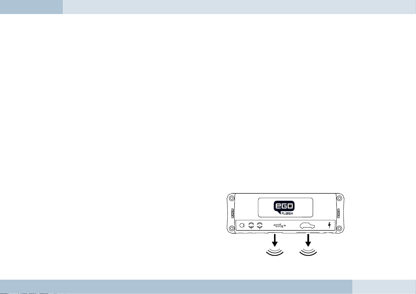
6.2.2 Selection of the installation location for the
electronics box
The Bluetooth
phone is installed in the electronics box. The antenna
®
antenna for the connection to the mobile
Fig. 02:
Signal transmission of
the Bluetooth® antenna
10 | 11

transmits directionally towards the front. For this reason,
during installation, ensure that the antenna faces into the
passenger cell (see Fig. 02). Vertical mounting is ideal.
Metallic screening between the front panel and the passenger
cell, such as metal or metallised plastic panels, are
®
unsuitable and may interfere with the Bluetooth
connection.
Locations behind the dashboard or in a metal-lined glove
compartment are also unsuitable.
A covering in plastic, fabric or wood presents no problems
whatsoever.
Suitable locations for the electronics box:
Passenger side, next to the middle console under the
paneling, model-specifi c installation console (dealer).
Our suggested installation locations are shown in the illustration on the right.
Further unsuitable locations are:
Leg and knee height, potential head impact zone, airbag infl ation space, engine compartment
6.2.3 Selection of the point of installation for the microphone
Suitable for the microphone:
Where voice can reach the microphone unhindered (distance
between the speaker and the microphone should be approx.
13.78 in), on the A-column (between windshield and driver’s
side window), next to the driver‘s sun visor, on the dashboard
Unsuitable for the microphone:
Close to the speakers (less than 31 in), under the dashboard,
in the air stream from open windows or air vents.
Fig. 03:
Installation locations
for the electronics box
Fig. 04:
Installation location
for microphone
The illustration
shows one of the
potential microphone
mounting locations.
Alternatively, the
microphone may be
attached to the sun
visor with the clip
provided.
EGO FLASH

q
6.2.4 Selection of site for installing the control unit with integrated display
Suitable for the control console:
In the space above the DIN installation shaft, close to the steering wheel (in an easily accessible and visible position)
Unsuitable for the control console:
Airbag infl ation space, potential head impact zones, out of reach of driver’s reach
6.3 Installation
DAMAGE TO ESSENTIAL VEHICLE COMPONENTS! – Essential vehicle components or wiring can be damaged when
drilling mounting holes or screwing in self-threading screws. Please make sure there is always suffi cient space behind
the screw holes and drilled holes!
6.3.1 Mounting the electronics box
Installation consoles for a number of
car models are available from your
dealer. These are designed to contain all
the system components, including the
electronics box. When it is not possible
to use an installation console, please
proceed as follows:
Defi ne the mounting points
Making sure that there is at least 2.8 in
space for the plug and socket connectors.
Mark the positions for the fi xing screws.
Fig. 05:
Electronics box
dimensions
12 | 13

Mounting the electronics box
For mounting the electronics box, use four self-threading screws and appropriate washers. We recommend size
“ST 2,9x25 DIN 7981”self-threading screws. These are ideal for the fi xing of the electronics box. Pre-drill the holes
with a 0.08 in drill.
6.3.2 Mounting the microphone
Defi ne the mounting location
The microphone holder has a self-adhesive strip on the back. The mounting location should have the same form and area
as the self-adhesive strip on the microphone holder. The location selected must allow the microphone cable to reach the
electronics box! Position the microphone with the head facing towards the direction of speech.
Cleaning and degreasing the mounting location
The mounting location must be clean and free from grease and dirt/dust. Prior to installation, clean the area with a
cleansing product containing ethyl alcohol. Only use products that do not damage plastics or varnished wood fi nishes
and are themselves free of oils or grease. Unsuitable cleansers are, for example, lighter fl uid, acetone, turpentine,
trichloroethylene and similar products.
Attaching the microphone holder
Peel off the protective backing from the self-adhesive strip. Hold the microphone holder at a distance of several
millimetres (about a quarter of an inch) above the desired mounting location. Re-check the positioning. Re-positioning
after mounting is no longer possible. Place the microphone holder on the mounting location and fi x by applying short and
light pressure.
EGO FLASH
Attaching the microphone
Attach the microphone by sliding it into the holder and position the microphone head towards the direction of speech.
6.3.3 Mounting the control unit with integrated display
Defi ne the mounting location
The control console is mounted on a smooth service by means of the self-adhesive pad provided. Make sure that the
location is within easy reach of the intended user.

q
Cleaning and degreasing the mounting location
The mounting location must be clean and free from grease and dirt/dust. Prior to installation, clean the area with
a cleansing product containing ethyl alcohol. Only use cleansing products that do not damage plastics or varnished
wood fi nishes and are themselves free of oils or grease. Unsuitable cleansers are, for example, lighter fl uid, acetone,
turpentine, trichloroethylene and similar products.
Attaching the control unit with integrated display
After defi ning the appropriate cable direction on the back of the console, fi x it by covering it with the self-adhesive pad.
Hold the control console at a distance of several millimetres (about a quarter of an inch) above the desired mounting
location. Re-check the positioning. Re-positioning the console after mounting is no longer possible. Apply the control
console to the proposed mounting location and fi x by applying short and light pressure.
6.4 Connection scheme
Installation for call reception for a car audio system with a mute input but without a phone input
With this connection option, voice playback is is emitted from the front right car speaker. During calls, the mute input
blocks the car audio signal.
NOTE: Please observe the information in section “6.5.1 Checking the mute inputs” on connecting the mute lead of the ISO
connecting cable.
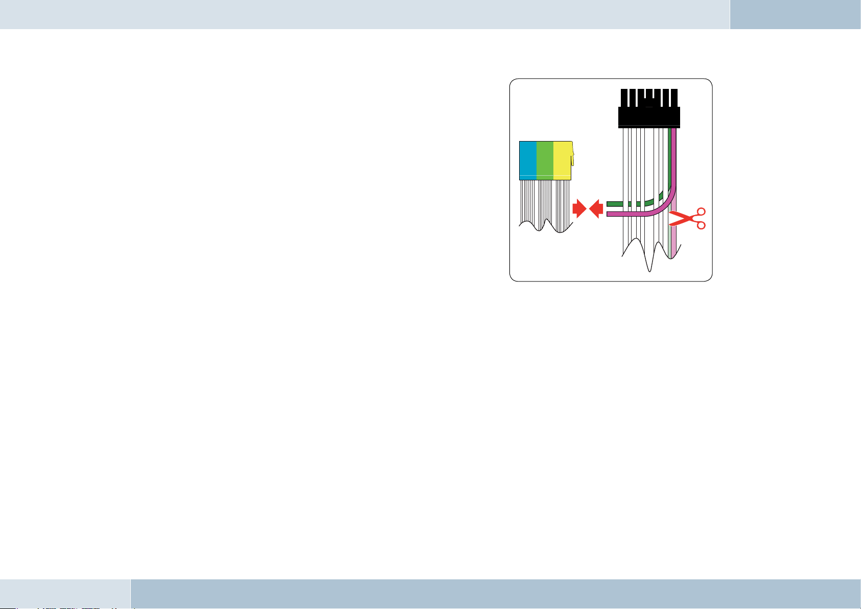
Installation for voice playback with a car audio system with phone and mute input options
With this connection option, voice playback comes through the car audio system speakers. During calls, the car radio
output is switched to the phone input by the mute input In order to access the phone input of your car audio system, the
speaker output of your EGO FLASH must be connected to the phone input of your car audio system. The purple and green
leads of the ISO cable must be connected to the car audio phone input for this option. The purple and green leads must be
disconnected from the ISO connector. The green lead (pin 14 of the 14-pin plug) should be connected to „Phone Out“, and
the purple lead (pin 7 of the 14-pin plug) to „Phone In +“ of the Mini-ISO socket.
14 | 15
For information on the phone connection options of your car audio
system, please consult the manufacturer‘s user manual.
q
NOTE: If your car audio system has different phone connection options
from those mentioned here, please consult a qualifi ed professional for
installation of the system. Furthermore, please read the section with
information on connecting the mute lead of the ISO connection cable,
“6.5.1 Checking the mute input”.
Fig. 06:
Connection for the
mini ISO connection
cable
EGO FLASH
6.5 Installation of the ISO connecting cable
1
2
3
4
The battery must be disconnected before starting cable installation. Disconnect the grounding cable from the negative pole
of the battery. The cable installation procedure is shown in the illustrations.
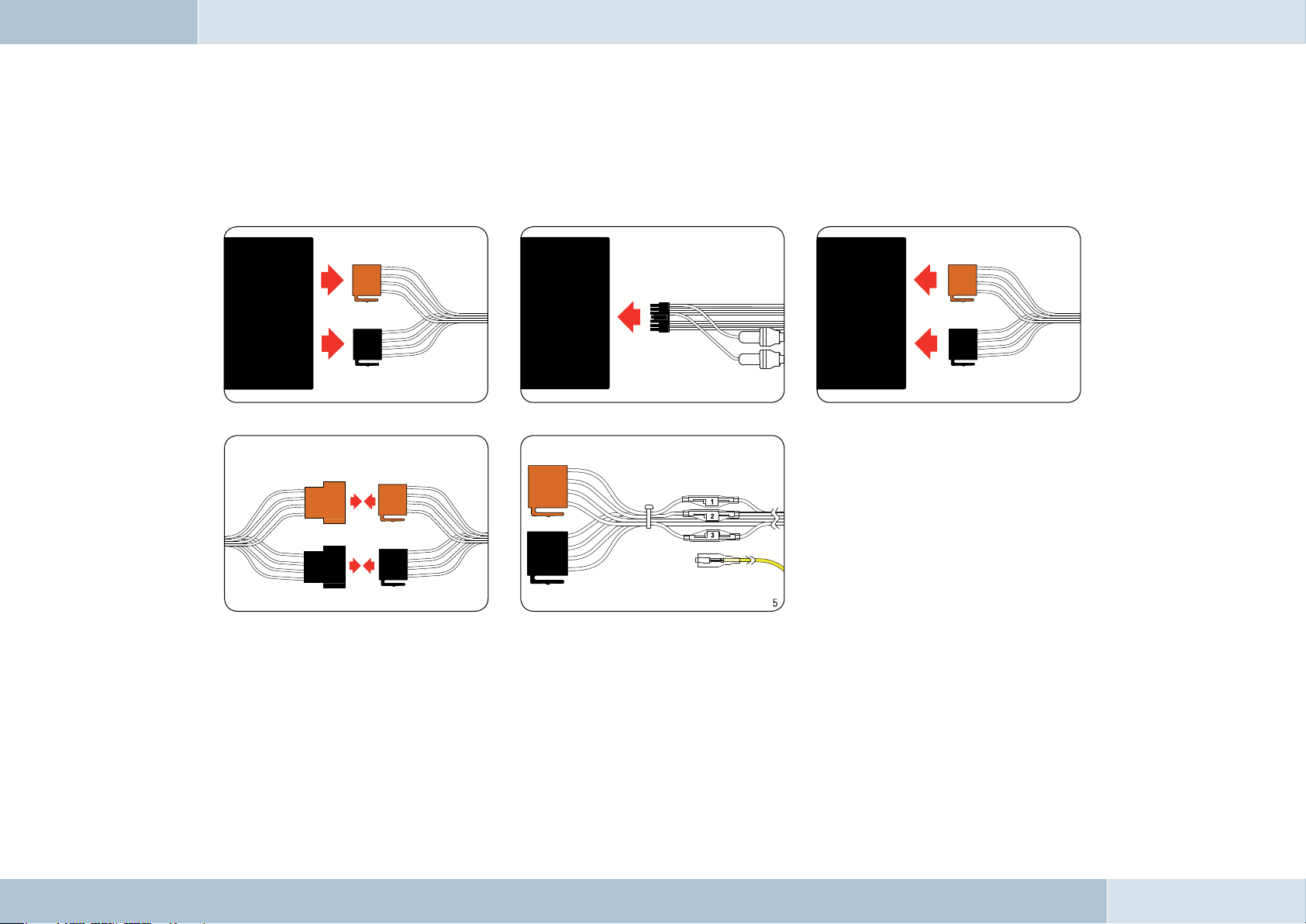
Fig. 07:
Installation
procedure
Connect 14-pin ISO
connecting cable to
EGO FLASH
Car audio
Car audio
Disconnect ca r wiring
harn ess from ca r radio
Electronics box
Connect EGO FL ASH ISO connector s to car
wiri ng harnes s ISO connec tors
Connect yello w mute lead to
one of th e three mute in puts
(see table)
When the installation is completed, reconnect the grounding cable to the negative pole of the battery.
Connect EGO FL ASH ISO
conne ctor to car r adio
6.5.1 Checking the mute inputs
Picture 5 of Fig. 07 shows mute inputs 1–3. The yellow mute lead of the hands-free system should be connected to one of
these inputs. Which mute input should be selected is shown in the tables:
16 | 17

Fig. 08:
Typ e-
dependent
pin allocation
Socket contact housing
Radio model Pin Wire colour Function
1
Audi,
Volkswagen,
Grundig
2
3
4
7
8
blue Ignition (15)
red Permanent positive (30)
brown Ground (31)
Mute
Wiring of power supply connectors
Socket wiring from
the rear (see table)
Plug wiring from
the rear
Socket contact housing
Radio model Pin Wire colour Function
1
Ford,
Mercedes,
Porsche,
Becker
Radio model Pin Wire colour Function
Blaupunkt
Radio model Pin Wire colour Function
Philips
2
3
4
7
8
1
2
3
4
7
8
1
2
3
4
7
8
red Permanent positive (30)
blue Ignition (15)
brown Ground (31)
Socket contact housing
red Permanent positive (30)
blue Ignition (15)
brown Ground (31)
Socket contact housing
red Permanent positive (30)
blue Ignition (15)
brown Ground (31)
Mute
Mute
Mute
21
43
65
87
Car audio
Autoradio
Elektronikbox
Electronics box
12
34
56
78
Fig. 09:
Plug wiring scheme
KFZ-Kabelbaum
Vehicle wiring harness
Fig. 10:
Connection system
EGO FLASH
 Loading...