

Mojack XT User Manual
Ver. 111716
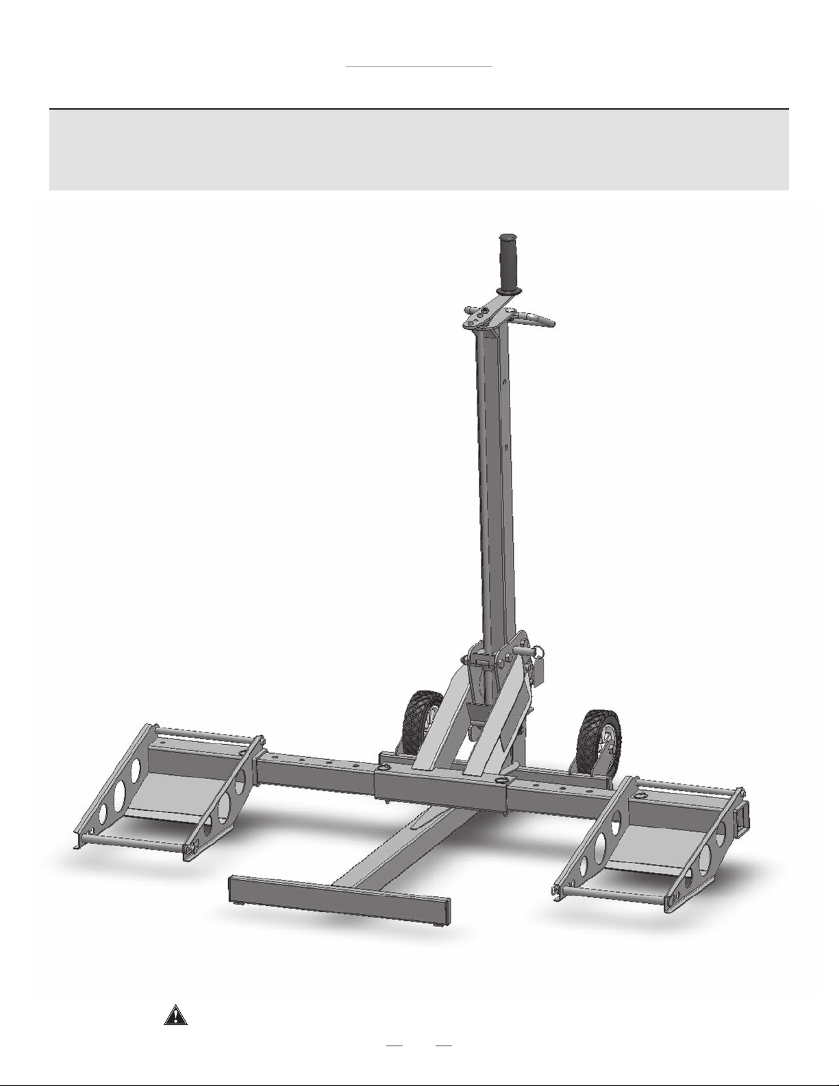
MoJack XT Lift
Introduction
This manual contains assembly, parts, operating, maintenance, adjustment and safety instructions for your
MoJack XT lift.
BEFORE USING YOUR MOJACK XT, CAREFULLY
READ THIS MANUAL IN ITS ENTIRETY.
By following these operating, maintenance and safety
instructions, you will prolong the life of your MoJack lift
and promote safe operation.
If additional information is needed, or should you
require a trained service mechanic, contact your
authorized MoJack equipment dealer or distributor.
All MoJack parts are thoroughly tested and inspected
before leaving the factory to ensure that they comply
with all relevant safety standards.
Need
Assistance?
Please DO NOT return this
product to the store.
Our Customer Service
Department is ready to help!
1-877-575-3173
Vous pouvez également transmettre votre question en ligne à l’adresse suivante :
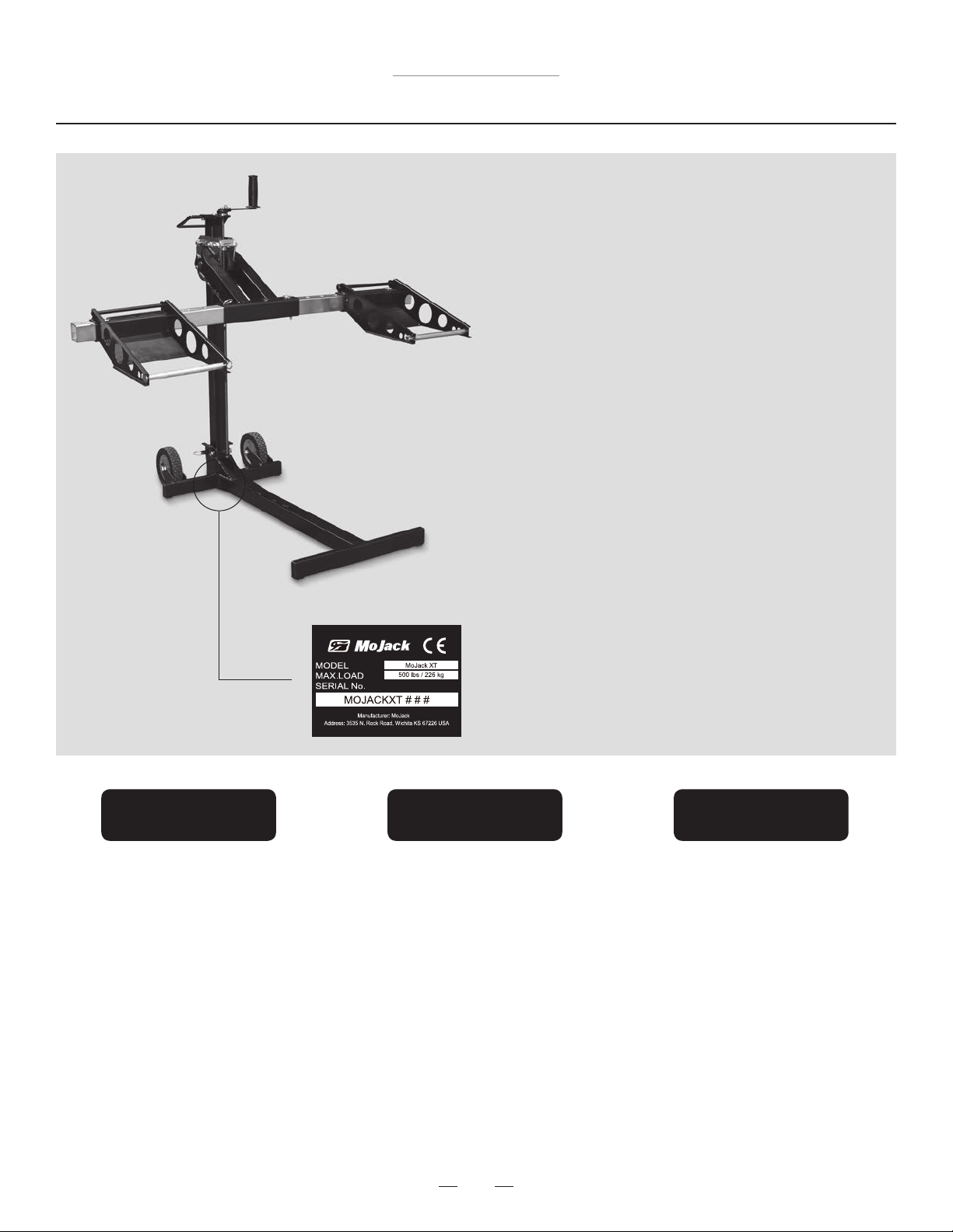
NOTE: Please save this manual for future reference.
NOTE: Location of unit Serial Number.
¿Necesita
ayuda?
¡NO devuelva este producto
a la tienda!
¡Nuestro Departamento de
Servicio de Atención al Cliente
está listo para ayudarle!
1-877-575-3173
Submit your questions online at:
Envie sus preguntas por Internet a:
Besoin
d’assistance ?
NE renvoyez PAS ce produit
au magasin .
Notre service clientèle est là
pour vous aider !
1-877-575-3173
www.theMoJack.com
Patent #s: U.S., 8,448,920 and 8,387,953
MoJack and the MoJack logo are registered trademarks of MoJack Distributors, LLC.
MoJack XT is a trademark of MoJack Distributors, LLC. All rights reserved.
© 2014 MoJack Distributors, LLC.
2

MoJack XT Lift
Warnings and Safety Instructions
Read and understand all safety and operating instructions before using the MoJack XT.
Never allow anyone unfamiliar with the safety or operating instructions to use the MoJack XT.
Follow all safety and servicing instructions provided by the lawn mower’s manufacturer before using
the MoJack XT.
Do not modify the MoJack XT in any way. Any modications will void any and all warranties and could
compromise your personal safety.
When using the MoJack XT, keep ALL bystanders at a safe distance away from the MoJack XT.
The MoJack XT must be used on a solid level surface.
Do not lift the front end and the back end of the mower at the same time.
Do not use MoJack XT lift for anything other than a mower, unless the proper accessory is used.
Always stop engine and remove key before beginning any work on the mower.
Never operate the mower’s engine while using the MoJack XT.
Do not exceed the lifting capacity of 500 lbs.
If the MoJack XT Tower is leaning while lifting or lowering the mower, this indicates an overload
condition. Remove the mower immediately.
Tower must be locked in place with the Tower Locking Pin before using the MoJack XT.
Carrier Locking Pin must be locked into Tower before starting any service on mower.
Do not remove safety warnings or decals from MoJack XT.
Before each use, always check for any worn, loose or damaged parts on the MoJack XT. If any
damaged parts are present, do not use the MoJack XT and contact MoJack at 1-877-575-3173.
Do not climb on mower while it is lifted, being lifted or being lowered.
No one should be on the mower while it is lifted, being lifted or being lowered.
After the mower is raised to a working height, always place wheel chocks (not included) behind the back tires
of the mower.
Wheel Pads must be equal distance from the Lift Arm to maintain proper balance.
Remove all mower attachments before using the MoJack XT.
Failure to follow these warnings may result in property damage and serious bodily injury or death.
IMPORTANT: The MoJack XT is intended for use with riding lawn mowers and riding lawn tractors only. Do not
exceed 500 lbs. It should never be used to service other types of machinery unless there is an approved MoJack
accessory tted for the type of machinery. Please consult you local MoJack dealer or distributor.
3

MoJack XT Lift
Warranty and Returns
LIMITED WARRANTY
For two years for residential use and one year for commercial use MoJack warrants the product against failure due to
defect in material or workmanship when product is used properly. MoJack will replace any defective part at no cost.
This warranty does not cover any product that has been altered or adjusted, or any product that has been misused or
abused. THIS IS THE CUSTOMER’S SOLE AND EXCLUSIVE REMEDY. MOJACK DISCLAIMS ALL IMPLIED WARRANTIES, INCLUDING THE WARRANTY OF MERCHANTABILITY AND FITNESS FOR A PARTICULAR PURPOSE. MOJACK
SHALL NOT BE LIABLE FOR ANY INCIDENTIAL OR CONSEQUENTIAL DAMAGES. SOME STATES OR PROVINCES DO
NOT ALLOW THE EXCLUSION OR LIMITATION OF THE IMPLIED WARRANTIES OR THE REMEDIES FOR BREACH OF
THE IMPLIED WARRANTIES, SO THESE EXCLUSIONS MAY NOT APPLY TO YOU. THIS LIMITED WARRANTY GIVES
YOU SPECIFIC LEGAL RIGHTS, AND YOU MAY ALSO HAVE OTHER RIGHTS WHICH VARY FROM STATE TO STATE
OR PROVINCE TO PROVINCE.
What does this warranty cover?
This warranty covers against a failure due to a defect in material or workmanship within two years of purchase for residential use and within one year of purchase for commercial use.
What does this warranty NOT cover?
This warranty does not cover any MoJack which has been altered or adjusted in any way from its original model.
It will not cover any MoJack which has been damaged due to misuse, abuse, accident or negligence. This warranty does
not cover incidental or consequential damages.
What is the period of coverage?
Two-year warranty for residential use, one-year for commercial use from date of purchase for the original owner.
What will MoJack do to correct problems?
We will replace any defective part (within the coverage period) at no charge.
How can I get service?
In order to be eligible for service under this warranty you MUST register your MoJack within thirty (30) days of
purchasing. You must keep your receipt as proof of date of sale. You can register your new MoJack on our website at
www.themojack.com or by calling our toll-free number 1-877-575-3173.
How do I contact MoJack about a warranty issue?
You can contact us from our website at www.themojack.com or by calling our toll-free number 1-877-575-3173.
Do I have other rights under State Law?
This warranty gives you specic legal rights, and you may also have other rights which vary from state to state.
What is the return policy?
Within thirty (30) days of the date that you receive your MoJack. Please contact MoJack for return policies and
procedures at our toll-free number 1-877-575-3173 or by email at info@themojack.com.
How do I make a return?
Contact us within the return period. We will issue you a Return Merchandise Authorization (RMA) to place on the outside
of the box. All merchandise must be shipped back in its original packaging. We will make arrangements for the MoJack
to be picked up by a national carrier.
In what form will I receive my refund?
This is at our discretion. If receiving a refund, please allow four weeks for the credit to process to your account. Return
service fees will be deducted from the amount of the refund.
Are shipping charges refundable?
No.
Does MoJack have a return service fee policy?
Yes. Returns and refunds impose an extra workload on our parts. Rather than pass this cost on to the customer through
higher product prices, we are consistent with others within our industry by requiring nominal service fees in the event of
returns. The service fee is 20%.
How do I contact MoJack?
You can call our toll-free number 1-877-575-3173 or by email at info@themojack.com.
4

MoJack XT Lift
Parts List
Item
No.
1
2
3
4
5
Qty.
1
1
1
2
2
6
Description
Tower
Lift Arm
Base
Wheel
Wheel Pads
Item
No.
6
7
8
9
10
Qty.
2
1
1
2
2
Description
Lift Arm Inserts
Grip Handle
Crank Handle
Support Rod
Safety Strap
8
7
2
1
6
10
10
Carrier
5
5
4
4
9
9
3
5

MoJack XT Lift
Hardware List
Item
No.
11
12
13
14
15
16
17
18
19
Qty.
1
2
3
3
3
4
1
1
2
Description
Cap Screw M12-1.75 X 80
Cap Screw M12-1.75 X 65
Carriage Bolt M8-1.25 X 20
Nylock Nut – M12-1.75
Nylock Nut – M8-1.25
Push Pin
Clevis Pin
Small Hair Pin
Large Hair Pin
11
Cap Screw M12-1.75 X 80
12
Cap Screw M12-1.75 X 65
13
Carriage Bolt M8-1.25 X 20
16
Push Pin
18
Small Hair Pin
14
Nylock Nut – M12-1.75
19
Large Hair Pin
Tools Needed for Assembly
15
Nylock Nut – M8-1.25
17
Clevis Pin
19mm Wrench (2) 13mm Wrench (1)
6
Assembly Instructions
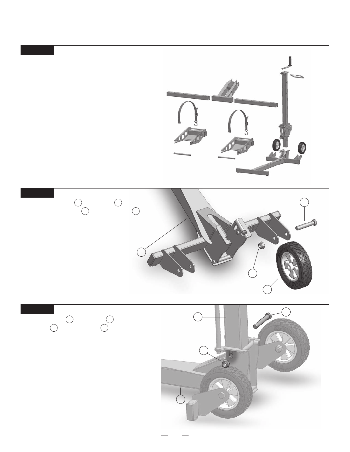
STEP 1
Remove MoJack XT from package.
Inventory items to be certain all parts and hardware
are present. If any parts or hardware are missing,
please contact MoJack at 1-877-575-3173 or
email us at parts@themojack.com.
MoJack XT Lift
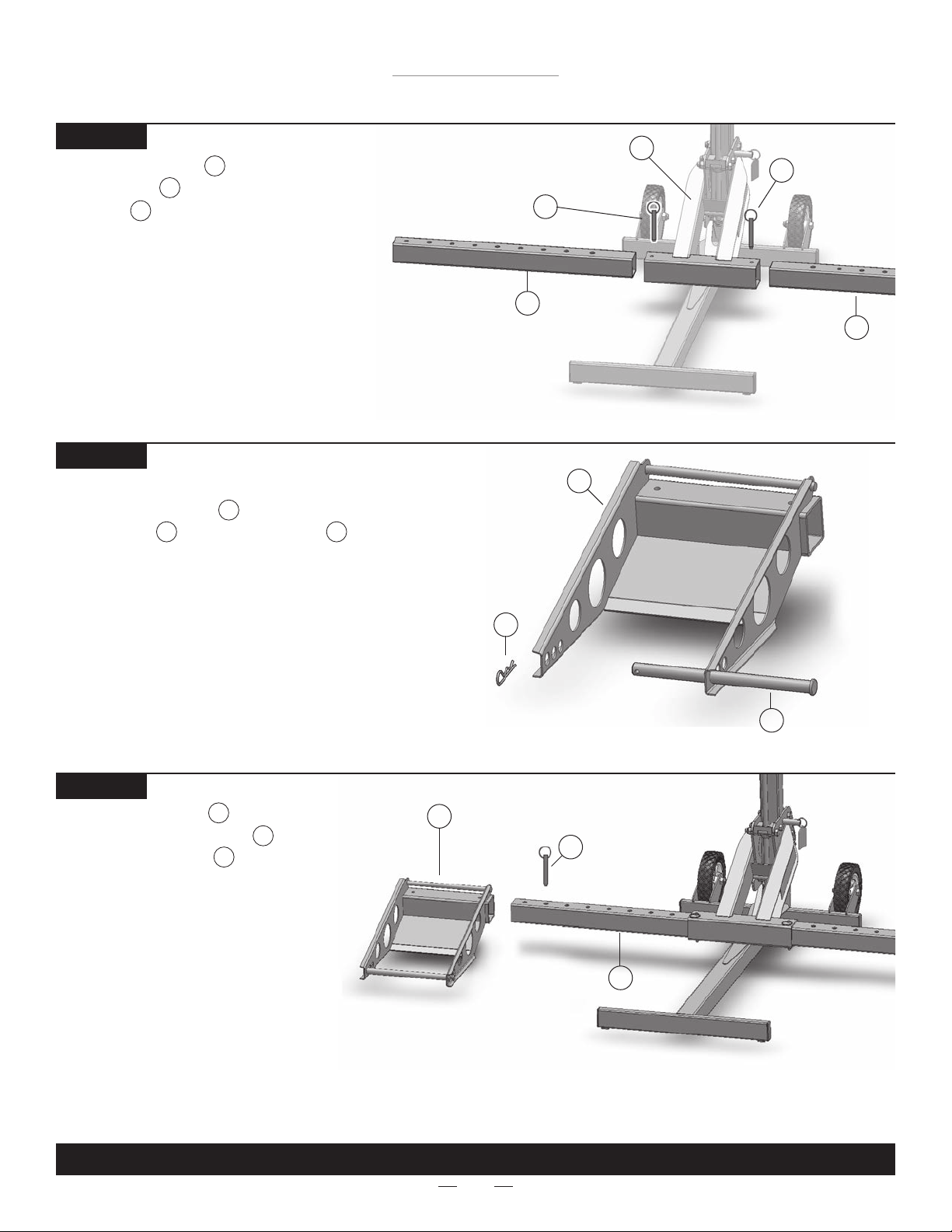
STEP 2
Assemble the Wheel to the Base
by inserting Cap Screw and Nylock Nut
and tighten. Repeat with second Wheel.
Note: Do not over tighten Nylock Nut.
STEP 3
Attach the Tower to the Base using
Cap Screw and Nylock Nut as shown.
Note: Do not over tighten Nylock Nut.
11 14
4 3
12 14
Base
1 3
Cap Screw
3
Tower
Nylock Nut
Nylock Nut
1
14
14
Wheel
4
11
12
Cap Screw
Base
3
7
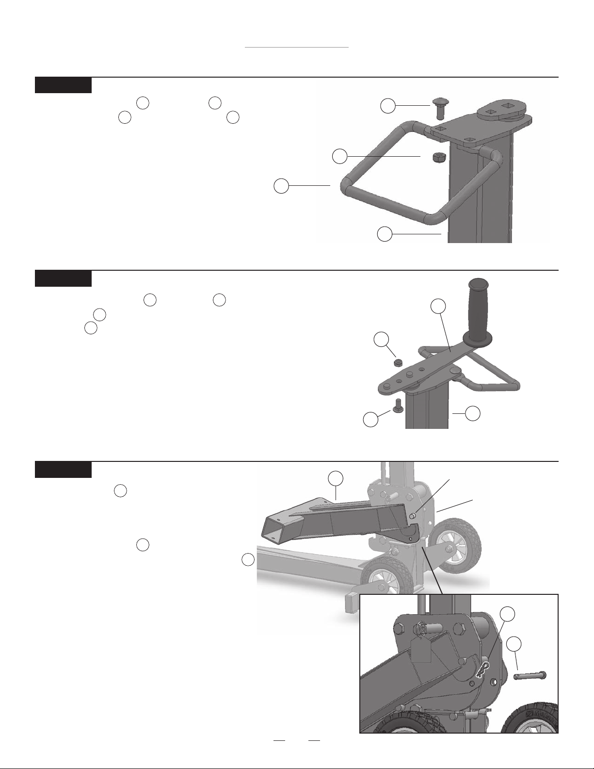
STEP 4
MoJack XT Lift
Assembly Instructions
Attach the Grip Handle to the Tower with
two Carriage Bolts and two Nylock Nuts .
7 1
13 15
Nylock Nut
Grip Handle
7
STEP 5
Attach the Crank Handle to the Tower by inserting
Carriage Bolt with threads facing up and fasten with
Nylock Nut .
13
15
18
Note: There are two holes in the Crank Handle. The hole
closest to the rubber grip will provide a 6” radius for cranking. The other hole will provide an 8” radius, making cranking easier. Use the hole that works best with your model of
lawn mower.
Carriage Bolt
15
Tower
Nylock Nut
Carriage Bolt
13
1
Crank Handle
15
13
8
Tower
1
STEP 6
Hang the Lift Arm on the Carrier by hooking
2
the slotted area of the Lift Arm under the top bar
of the Carrier. Lift Arm must be inserted from the
front and then lowered which fastens Lift Arm into
place. Insert Clevis Pin through the hole in the
Carrier and lock by fastening the Small Hair Pin
17
18
to the Clevis Pin.
Lift Arm
8
2
Top Bar of Carrier
Carrier
Small
18
Hair Pin
Clevis
17
Pin
MoJack XT Lift
Assembly Instructions
STEP 7
Slide Lift Arm Inserts into both sides
of the Lift Arm and secure with
Push Pins as shown.
16
6
2
STEP 8
Ready the Wheel Pads for installation by adding
Support Rods and Large Hair Pins .
11 19
5
Push Pin
Lift Arm Insert
Wheel Pad
Lift Arm
2
Push Pin
16
16
6
Lift Arm Insert
6
5
STEP 9
Slide the Wheel Pads onto both
sides of the Lift Arm Inserts and
secure with Push Pins .
5
6
16
Note: The Wheel Pads can be moved in
or out to t different mower widths. Use
the conguration that works best with
your model of lawn mower.
Large Hair Pin
Wheel Pad
5
19
16
Lift Arm Insert
Push Pin
6
Support Rod
11
THIS COMPLETES ASSEMBLY.
9
MoJack XT Lift
Operating Instructions
Some steps of the Operating Instructions are repeated from the
Assembly Instructions. The Operating Instructions will show a full
working cycle of the MoJack XT.
Before using the MoJack XT, carefully read this manual in its entirety.
10
MoJack XT Lift
Operating Instructions
Preparing the MoJack XT for Use (Steps 1 - 8)
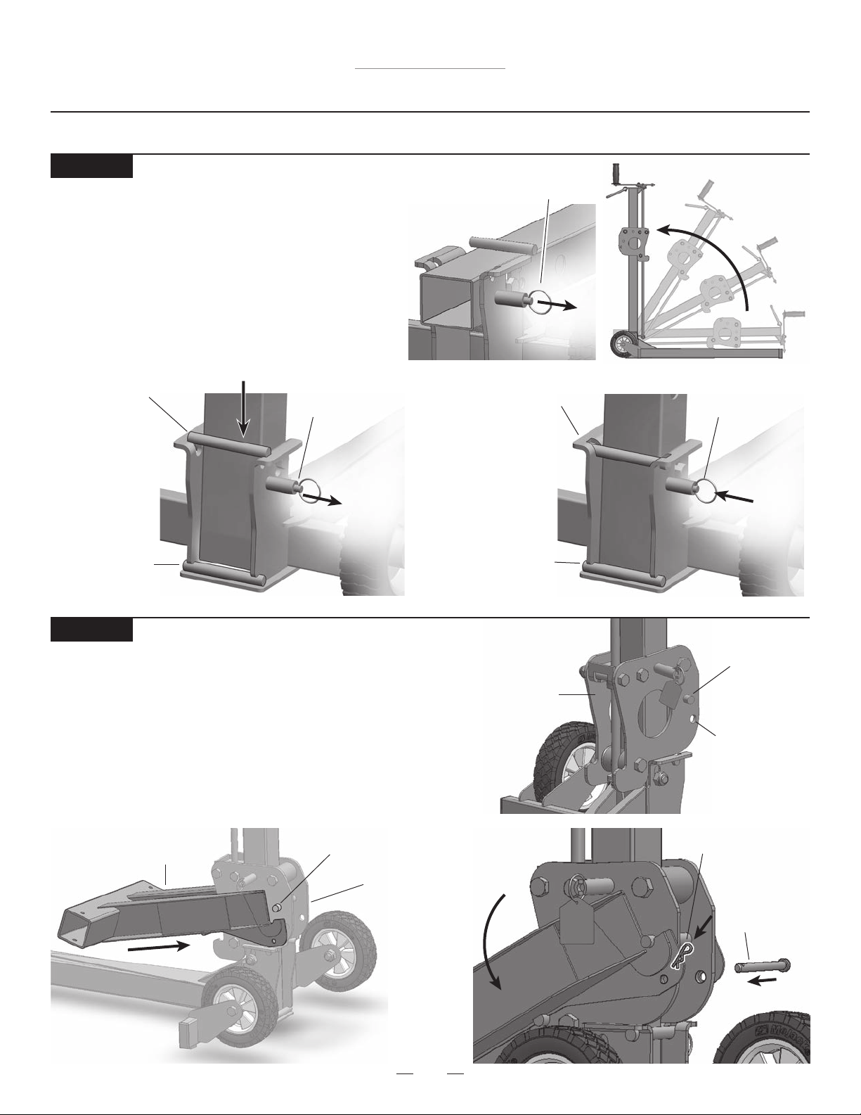
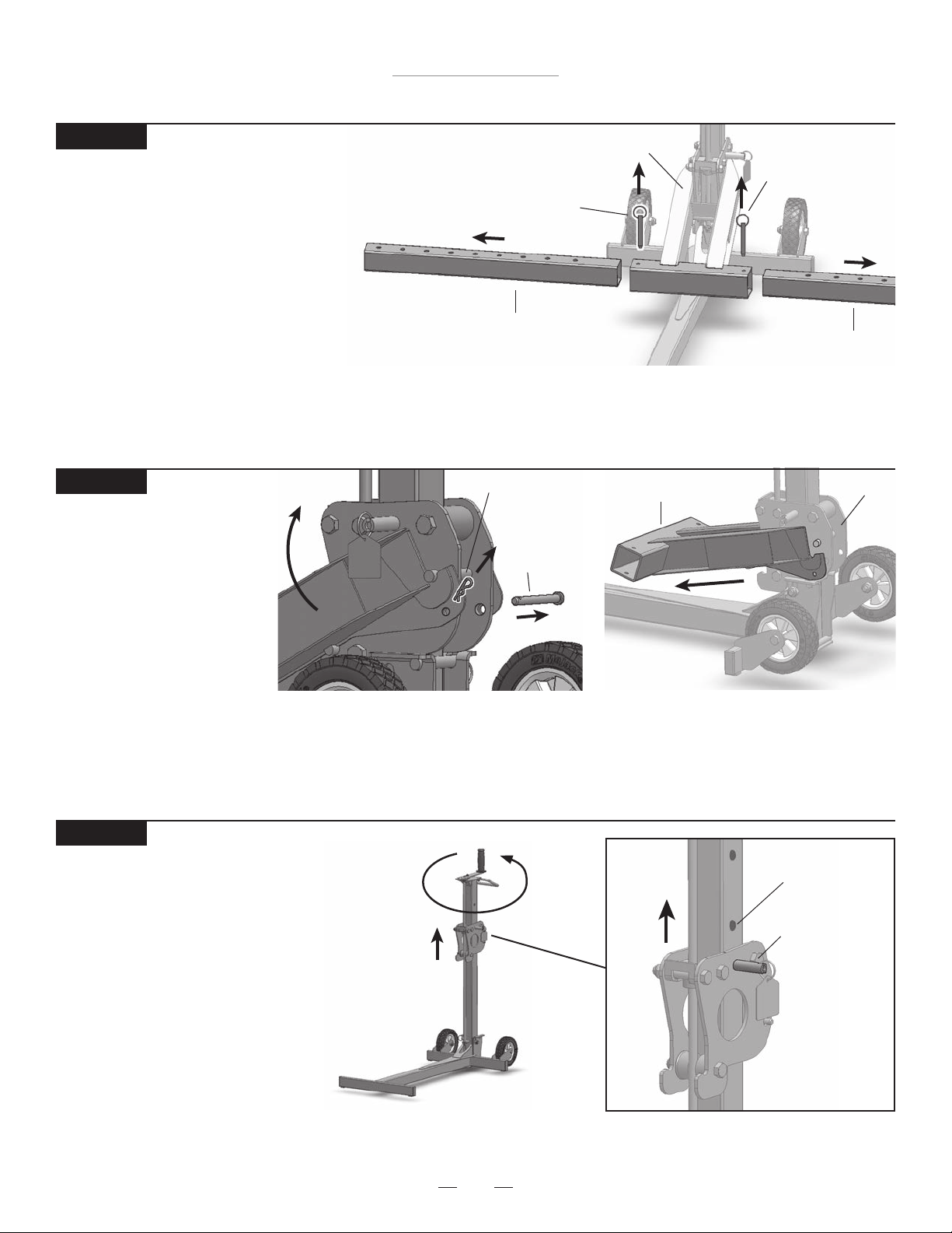
STEP 1
Unfolding MoJack XT
• Pull locking pin out to unlock.
• Raise the Tower by pulling up on the Grip Handle.
Once the Tower is in the vertical position, lift up on
the Grip Handle and drop the Tower into the Base.
• The tower will be securely locked in place when the
locking pin retracts and the tower is snug in the
channel behind the crossbar.
Drop Tower into Base
Crossbar
When Tower is
above the bar,
unit is NOT
locked and
UNSECURE.
Tower Locking Pin
(unlocked position)
Tower Locking Pin
(unlocked position)
Crossbar in
channel
When Tower sits
behind the bar,
unit is locked
and
fully secure.
Tower Locking
Pin
(locked position)
STEP 2
Installing Lift Arm
• Hang the Lift Arm on the Carrier by hooking the slotted area
of the lift Arm under the top bar of the Carrier. Lift Arm must
be inserted from the front and then lowered which fastens
Lift Arm into place.
• Secure Lift Arm to Carrier with Clevis Pin and Small Hair Pin.
Lift Arm
Top Bar of Carrier
Carrier
Top Bar
Carrier
Clevis Pin
hole
Small Hair Pin
Clevis Pin
11
MoJack XT Lift
Operating Instructions
STEP 3
Installing Lift Arm Inserts
• Slide Lift Arm Inserts into both sides of the
Lift Arm and secure with Push Pins.
STEP 4
Installing Wheel Pads
• Slide Wheel Pads onto Lift Arm Inserts and
temporarily secure with Push Pins.
Lift Arm
Push Pin
Push Pin
Lift Arm Insert
Lift Arm Insert
Push Pin
Wheel Pad
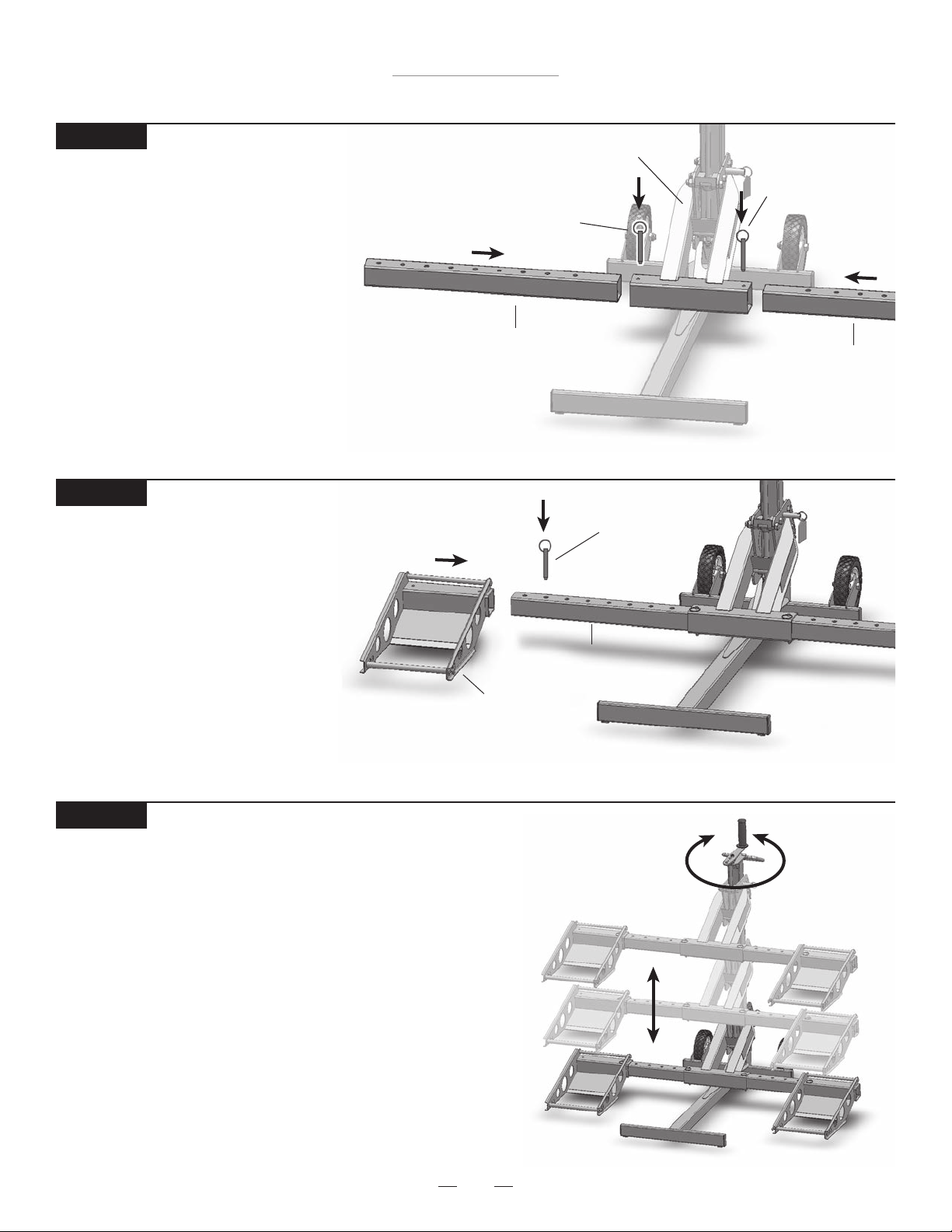
STEP 5
Familiarize Yourself with the MoJack XT
• Practice raising and lowering the Lift Arm before attempting to
lift the mower (see Steps 12 – 16 on how to raise and lower
the Lift Arm).
• Practice Step 21 if you intend to raise or lower the mower with
a drill attachment.
Lift Arm Insert
12
MoJack XT Lift
Operating Instructions
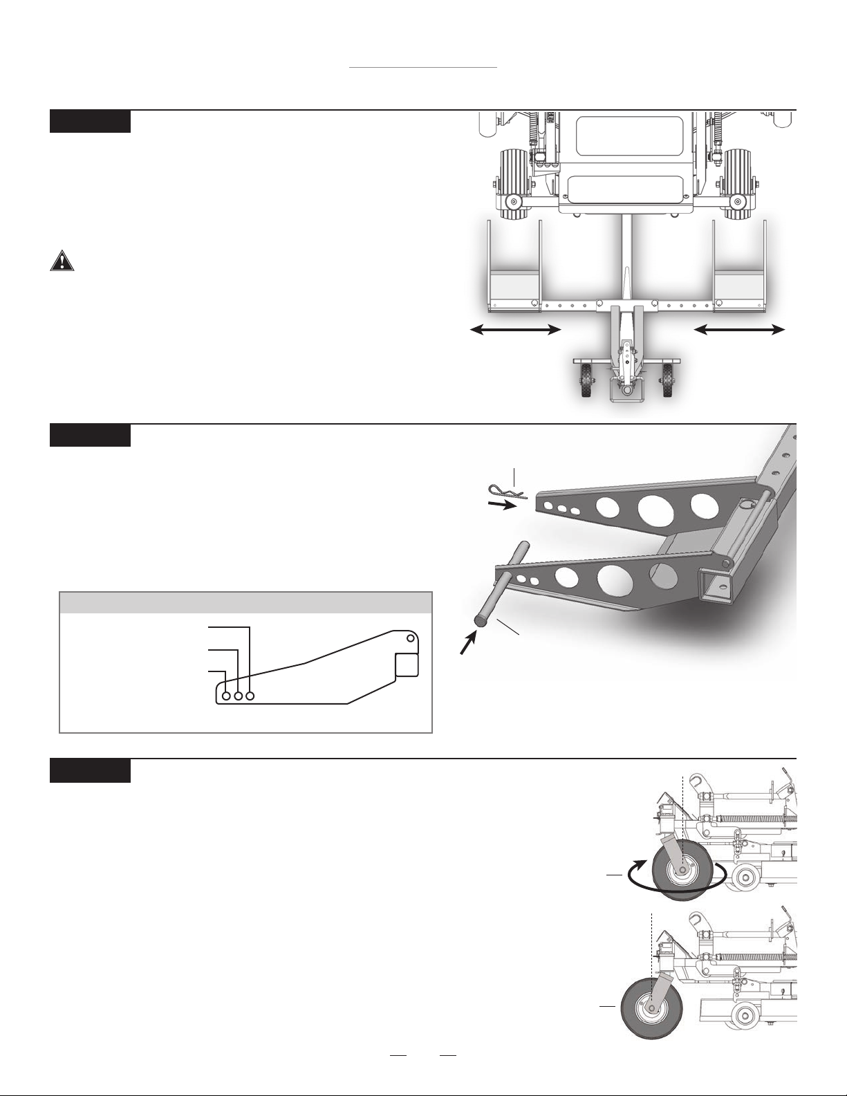
STEP 6
Aligning Wheel Pads to Fit Mower
• Place the front tires of mower 6” in front of the Wheel Pads.
• Remove Push Pins and align the Wheel Pads so that the front
mower tires will be centered on the Wheel Pads.
• Replace the Push Pins to lock the Wheel Pads to the Lift Arm.
Wheel Pads must be equal distance from the Lift Arm to
maintain proper balance.
STEP 7
Adjusting Support Rods for Proper Tire Size
• Adjust Support Rods on Wheel Pads to accommodate the
front tire size of the mower. Please refer to the chart below
for proper Support Rod placement based on the diameter
of the mower’s front tires.
• Secure Support Rods to Wheel Pads with Large Hair Pins.
SUPPORT ROD GUIDE FOR TIRE SIZES
10” - 11.5” (25cm - 29cm)
12” - 15” (30cm - 38cm)
15.5” - 17” (39cm - 44cm)
See page 20 for more more detailed guide.
STEP 8
Reverse Front Tires of Mower (optional – if not applicable, skip to Step 9)
• In some cases, the mower deck or anti-scalping wheels will hit the
Lift Arm while the mower is being raised. This is often the case if
part of the deck (including the anti-scalping wheels) protrudes past
the center line of the front wheels of the mower.
• Rotate the front tires 180° so that they are in the reverse position.
• Remove the Support Rods from the Wheel Pads and slide the
MoJack XT underneath the mower.
• Secure the Support Rods to Wheel Pads with Large Hair Pins.
Large Hair Pin
Support Rod
Forward
Wheel
Position
13
Reverse
Wheel
Position
MoJack XT Lift
Operating Instructions
Using the MoJack XT (Steps 9 - 16)
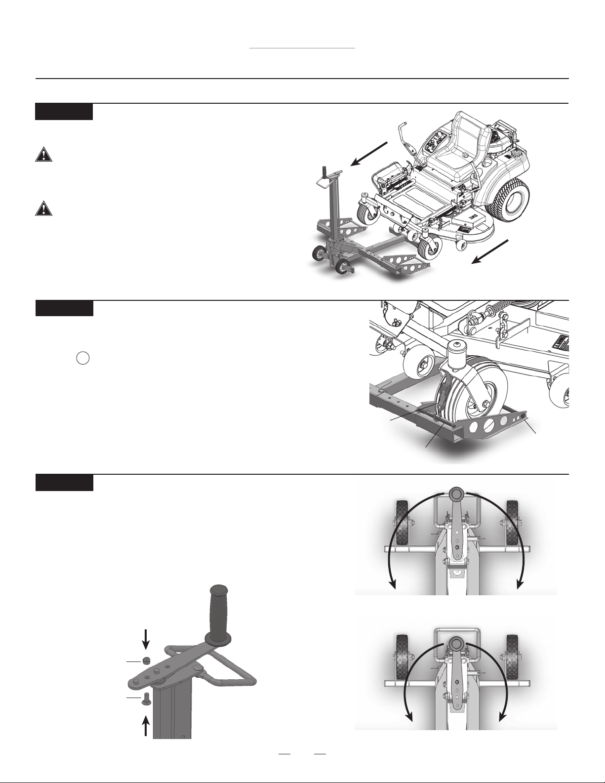
STEP 9
Move Mower onto MoJack XT
The MoJack XT must be used on a solid
level surface.
• Drive or roll the mower onto the Wheel Pads.
Stop engine and remove the key.
STEP 10
Strapping Front Mower Tires to Wheel Pads
• Secure the front mower tires to the Wheel Pads using the Safety
Straps . Secure the hook on the Safety Strap to the Wheel Pad Cross
Bar and insert the Support Rod into the loop on the Safety Strap by detaching the Support Rod and then sliding the Safety
Strap Loop through and reattaching the Support Rod.
• Tighten the Safety Straps over the top of the tires
to secure mower to Wheel Pads.
STEP 11
Adjusting the Crank Handle (optional)
• The optimal Crank Handle length is in the longer setting. Some
mowers have brush guards or larger hoods that interfere with
the longer Crank Handle. The Crank Handle can be adjusted by
removing the Nylock Nut and Carriage Bolt and re-attaching in
the shorter setting.
10
Safety Strap
Wheel Pad Cross Bar
Support Rod
Longer Setting – 8” Radius
Nylock Nut
Carriage Bolt
Shorter Setting – 6” Radius
14
MoJack XT Lift
Operating Instructions
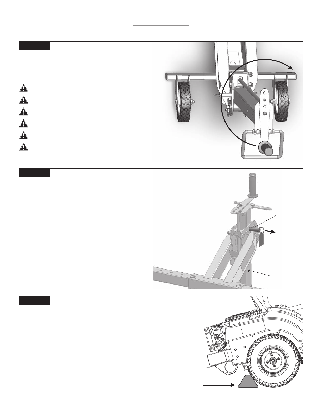
STEP 12
Raising the Mower
• Raise the mower by rotating the Crank Handle clockwise.
• See Step 22 for raising the mower with drill attachment.
Do not attempt to lift more than 500 lbs.
The MoJack XT must be used on a solid level surface.
The engine must be turned off and key removed.
The mower must be in neutral.
The parking brake must be off during this step.
The Safety Straps must be rmly tightened.
STEP 13
Raising Lift Arm to Locking Position
• Raise the Lift Arm until the Carrier Locking Pin drops into the
Safety Hole.
• The Carrier Locking Pin automatically drops into the Safety Holes as
the Carrier passes the Safety Holes on the Tower when raising.
• Note: When lowering the Lift Arm, the Carrier Locking Pin
must be held out by the operator until it clears the bottom
Safety Hole.
STEP 14
Preparing the Mower for Service
• Place wheel chocks (not included) behind the back tires of the mower.
• Now apply the parking brake on the mower.
• The Carrier Locking Pin must be locked into one of the two
Safety Holes.
Carrier
Locking
Pin
Pull Out
to
Unlock
and
Lower
Safety Hole
15
Wheel Chock
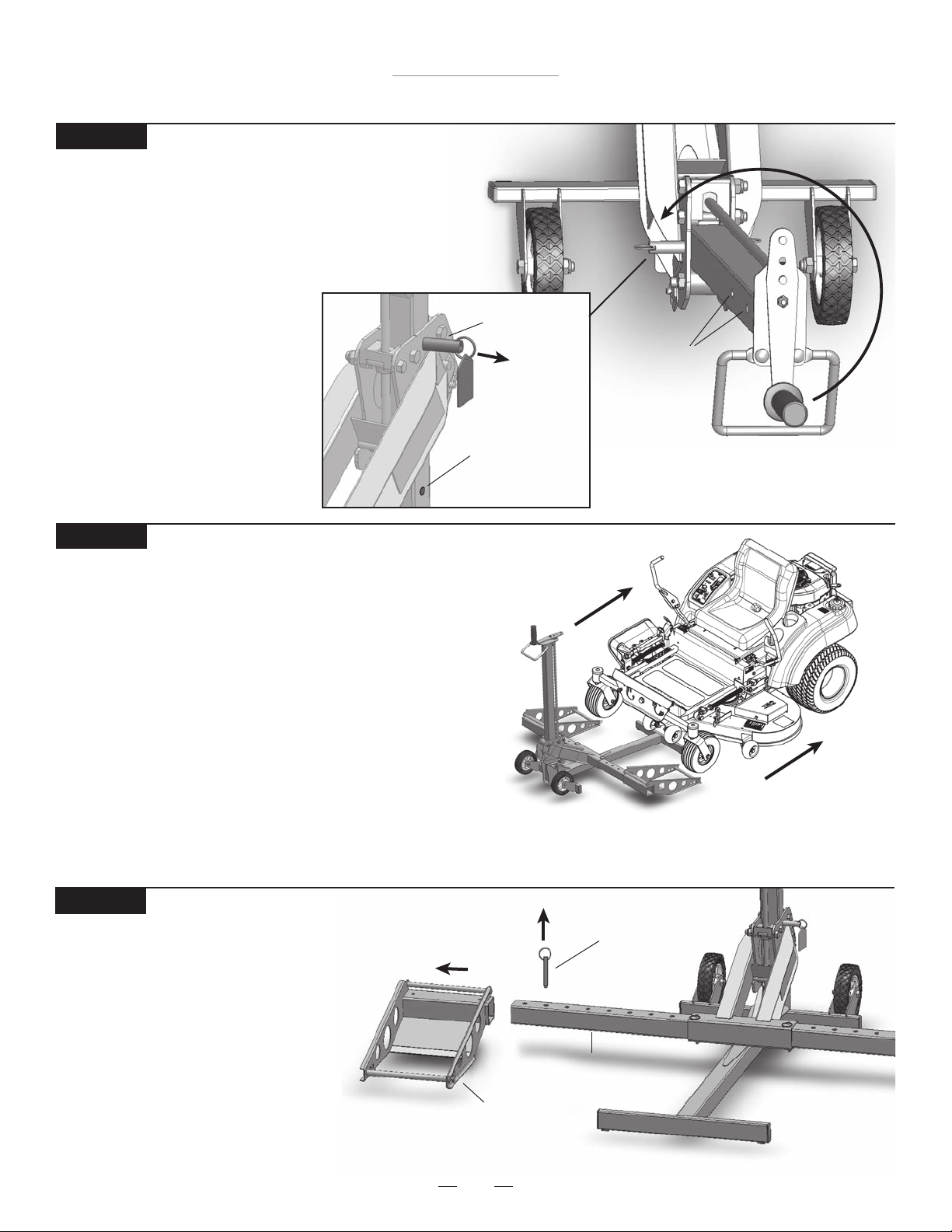
STEP 15
Lowering the Mower
• Remove wheel chocks.
• Release the parking brake.
• Mower must be in neutral.
• Pull and hold the Carrier Locking Pin
out and turn the Crank Handle
counter clockwise until
Wheel Pads are rmly on
the ground. The Carrier
Locking Pin must be pulled
out until it clears the bottom
Safety Hole.
MoJack XT Lift
Operating Instructions
Carrier
Locking
Pin
Safety Holes
Pull Out
to Unlock
and Lower
Safety Hole
STEP 16
Removing the Mower from the MoJack XT
• Remove the Safety Straps from front mower tires.
• Removing Support Rods is optional during this step.
• Drive or roll the mower off of the Wheel Pads.
Preparing the MoJack XT for Storage (Steps 17 - 20)
STEP 17
Removing the Wheel Pads
• Remove Wheel Pad Push Pins
and pull Wheel Pads out from
the Lift Arm Inserts.
• Store the Push Pins in the
Wheel Pads.
Push Pin
Lift Arm Insert
Wheel Pad
16
MoJack XT Lift
Operating Instructions
STEP 18
Removing LIft Arm Inserts
• Remove Lift Arm Push Pins and pull
Lift Arm Inserts from the Lift Arm.
• Store the Push Pins in the Lift Arm.
STEP 19
Unhooking the Lift Arm
• Remove Small Hair Pin
and Clevis Pin from Lift Arm.
• Unhook the Lift Arm from
the Carrier.
• Store the Small Hair Pin
and Clevis Pin in the
Lift Arm.
Push Pin
Lift Arm Insert
Small Hair Pin
Clevis Pin
Lift Arm
Lift Arm
Push Pin
Lift Arm Insert
Carrier
STEP 20
Raise Carrier
• Raise the Carrier by turning the
Crank Handle clockwise until
the Carrier Locking Pin drops
into the safety hole.
Safety Hole
Carrier
Locking
Pin
17
MoJack XT Lift
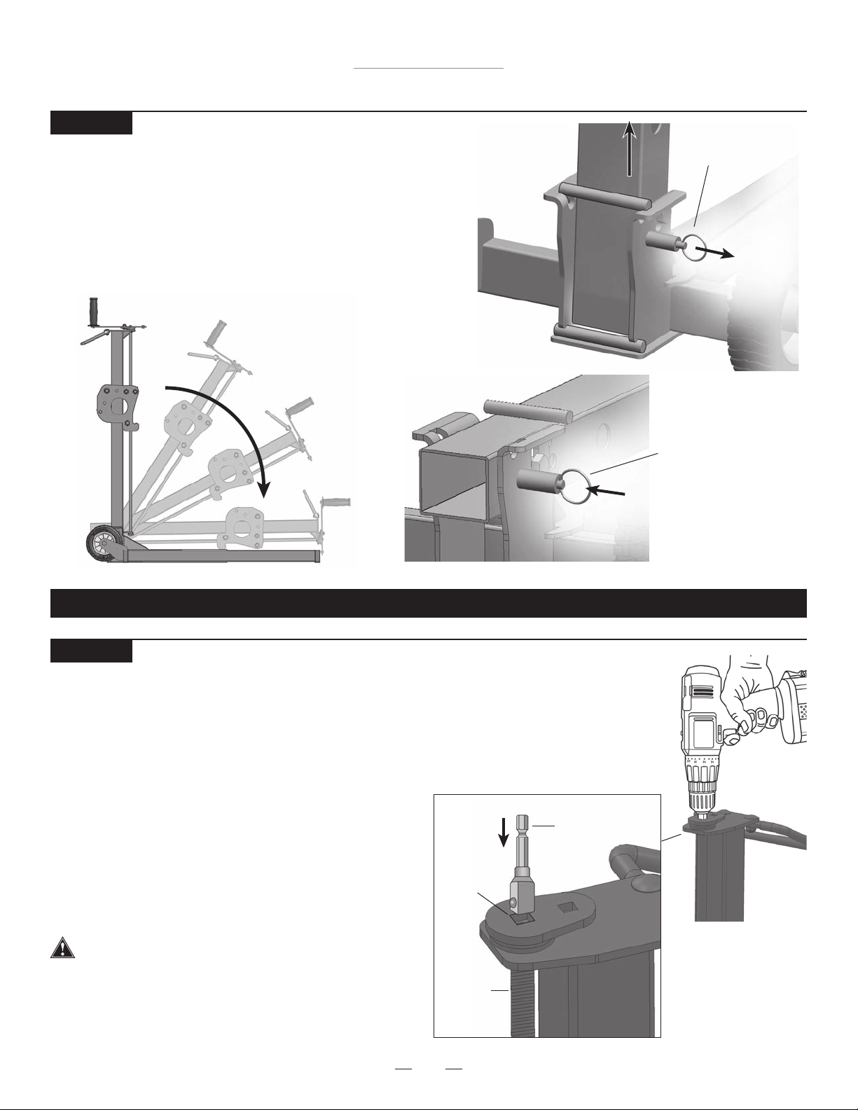
STEP 21
Folding the MoJack XT
• Pull locking pin out to unlock.
• Raise the Tower out of the Base by pulling up on the
Grip Handle and then lower the Tower.
• The tower will be securely locked in place when the
locking pin retracts.
Lift Tower
out of Base
Tower Locking Pin
(unlocked position)
Tower Locking
Pin
(locked position)
THE MOJACK XT IS NOW READY FOR STORAGE OR TRANSPORT.
STEP 22
Raising the MoJack XT with a power drill (optional)
• The MoJack XT can be raised or lowered by using a
variable speed corded drill (7 amp minimum) or variable
speed cordless drill (18V minimum).
• The drill will require a 3/8” square driver (not provided).
• Remove Crank Handle by taking out the nut and bolt
which reveals the 3/8” Square Receiver.
• Firmly insert the 3/8” driver in the Square Receiver.
Rotate the drill forward (clockwise) to raise
the Lift Arm and rotate the drill in reverse
(counterclockwise) to lower the Lift Arm.
• Carrier Locking Pin must be pulled out when
lowering until it clears the bottom Safety Hole.
Operator must have a rm grip on the drill before
raising or lowering the Lift Arm.
• Follow all other operating instructions while using the
drill attachment.
• Replace the Crank Handle for future use.
3/8”
Square
Driver
Square
Receiver
Screw
Thread
18
 Loading...