

Page 1
Model 45501
Modelo 45501
Instructions for Assembly and Operation
Caution: Very important to read instructions of the cylinder and locking bar to safely operate the lift.
Instrucciones de ensamblaje y de manejo
Precaución: Muy importante leer las instrucciones del cilindro y la barra de bloqueo
para operar de manera segura el ascensor.
Page 2
INTRODUCTION
This manual contains assembly, parts, operating, maintenance, adjustment and safety
instructions for your MoJack HDL lift.
BEFORE USING YOUR MOJACK HDL,
CAREFULLY READ THIS MANUAL IN ITS
ENTIRETY.
By following these operating, maintenance and
safety instructions, you will prolong the life of
your MoJack lift and promote safe operation.
If additional information is needed, or should you
require a trained service mechanic, contact your
authorized MoJack equipment dealer or distributor
or call MoJack at 1-877-575-3173.
All MoJack parts are thoroughly tested and inspected before leaving the factory to ensure that
they comply with all relevant safety standards.
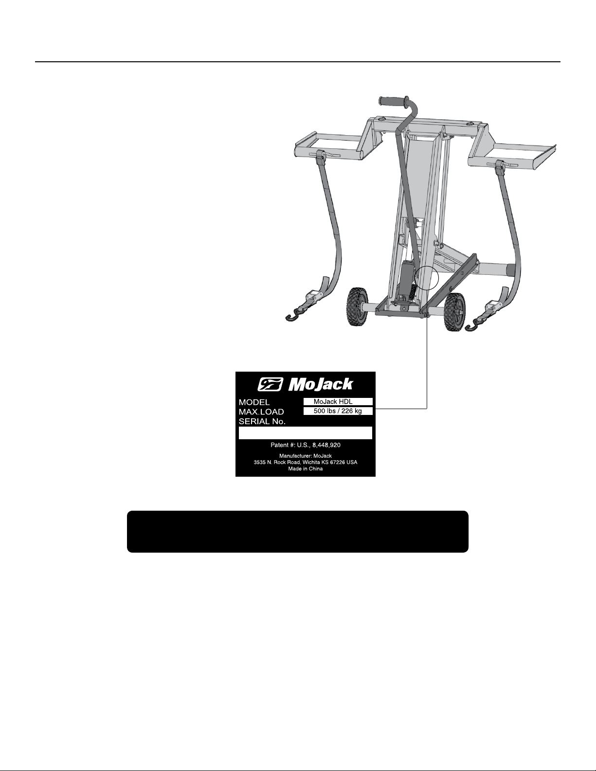
NOTE: Please save this manual for future reference.
NOTE: Location of unit Serial Number.
Need Assistance?
Please DO NOT return this product to the store.
Our Customer Service Department is ready to help!
1-877-575-3173
Submit your questions online at:
www.theMoJack.com
Patent #: U.S., 8,448,920
MoJack and the MoJack logo are registered trademarks of MoJack Distributors, LLC.
MoJack HDL is a trademark of MoJack Distributors, LLC. All rights reserved.
2
© 2013 (MoJack Distributors, LLC)
Page 3

WARNINGS AND SAFETY INSTRUCTIONS
Read and understand all safety and operating instructions before using the mower lift.
Never allow anyone unfamiliar with the safety or operating instructions to use the lift.
Follow all safety and servicing instructions provided by the lawn mower’s manufacturer before using
the lift.
Do not modify the lift in any way. Any modications will void any and all warranties and could
compromise your personal safety.
When using the lift, keep ALL bystanders at a safe distance away from the mower lift.
The lift must be used on a solid level surface.
Only lift the FRONT end of the mower.
Do not lift the front end and back end of the mower at the same time.
Do not exceed the lifting capacity of 500 lbs. (249 kg) front end weight. If you have a question regarding
weight of your machine, please contact Customer Service at 1-877-575-3173.
Only use the lift for mowers that properly ts in the provided wheel pads. (ie. 10” to 17” diameter and within
the inside to outside wheel measurements of 18.5” to 47.5”).
Both Left and Right Wheel pads must be equal distance from the T-bar to maintain proper balance.
Always stop engine and remove key before beginning any work on the mower.
Always place wheel chocks (not included) behind the back tires of the mower before beginning
maintenance. For additional safety, you may apply the parking brake after the wheel chocks are in place.
Never operate the engine while using the mower lift.
Do not remove safety warnings or decals from lift.
Please make sure that the space below the mower is big enough to work safely under the mower.
Please make sure that the mower is stable enough for work.
Failure to follow these warnings may result in property damage and serious bodily injury or death.
IMPORTANT: The mower lift is intended for use with mowers only. Do not exceed 500 lbs. (249 kg) front end weight.
It should never be used to service other types of machinery.
French Canadian language manuals are available upon request. Please contact 1-877-575-3173 to request an
alternative language owners manual kit.
Manuels de compétence linguistique canadiens français sont disponibles sur demande. S’il vous plaît contacter
1-877-575-3173 pour demander un kit manuel du propriétaire de l’autre langue.
3
Page 4

WARRANTY
LIMITED WARRANTY
For two years for residential use and one year for commercial use MoJack warrants the product against failure due to defect in material
or workmanship when product is used properly. MoJack will replace any defective part at no cost. This warranty does not cover any
product that has been altered or adjusted, or any product that has been misused or abused. THIS IS THE CUSTOMER’S SOLE AND
EXCLUSIVE REMEDY. MOJACK DISCLAIMS ALL IMPLIED WARRANTIES, INCLUDING THE WARRANTY OF MERCHANTABILITY
AND FITNESS FOR A PARTICULAR PURPOSE. MOJACK SHALL NOT BE LIABLE FOR ANY INCIDENTIAL OR CONSEQUENTIAL
DAMAGES. SOME STATES OR PROVINCES DO NOT ALLOW THE EXCLUSION OR LIMITATION OF THE IMPLIED WARRANTIES OR
THE REMEDIES FOR BREACH OF THE IMPLIED WARRANTIES, SO THESE EXCLUSIONS MAY NOT APPLY TO YOU. THIS LIMITED
WARRANTY GIVES YOU SPECIFIC LEGAL RIGHTS, AND YOU MAY ALSO HAVE OTHER RIGHTS WHICH VARY FROM STATE TO
STATE OR PROVINCE TO PROVINCE.
What does this warranty cover?
This warranty covers against a failure due to a defect in material or workmanship within two years of purchase for residential use and
within one year of purchase for commercial use.
What does this warranty NOT cover?
This warranty does not cover any jack which has been altered or adjusted in any way from its original model. It will not cover any jack
which has been damaged due to misuse, abuse, accident or negligence. This warranty does not cover incidental or consequential
damages.
What is the period of coverage?
Frame: 2 year for Residential. 1 year for Commercial
Hydraulic Cylinder: 1 year.
What will be done to correct problems?
We will replace any defective part (within the coverage period) at no charge.
How can I get parts service?
In order to be eligible for service under this warranty you MUST register your jack within thirty (30) days of purchasing. You must keep
your receipt as proof of date of sale. You can register your new jack on our website at www.themojack.com or by calling our toll-free
number 1-877-575-3173.
How do I contact someone about a warranty issue?
You can contact our toll-free number 1-877-575-3173.
Do I have other rights under State Law?
This warranty gives you specic legal rights, and you may also have other rights which vary from state to state.
What is the return policy?
Please refer to the Return Policy and Procedures of your place of purchase for returns and refunds.
4
Page 5
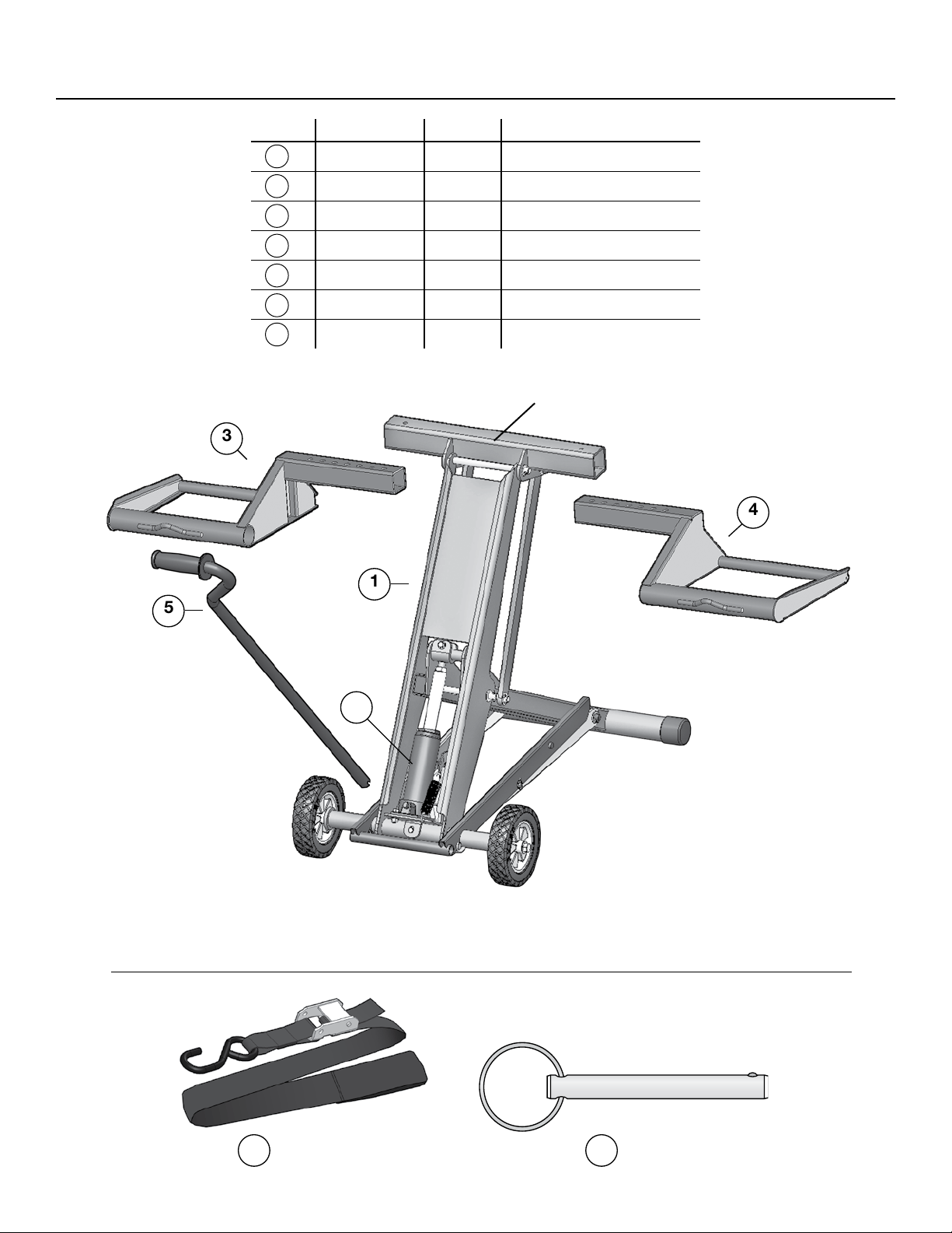
PARTS AND HARDWARE LIST
ITEM
1
2
3
4
5
6
7
PART #
518-0055
518-0030
518-0031
518-0032
518-0047
009-0007
001-0039
QTY.
1
1
1
1
1
2
2
DESCRIPTION
HDL Mower Lift
Hydraulic Cylinder - 2 Ton
Left Wheel Pad
Right Wheel Pad
Handle
Safety Straps
Push Pins
T-Bar
3
4
1
5
2
3 locking positions: 18”, 21”, 26”
FRONT OF LIFT
Safety Strap
6
Push Pin
7
5
Page 6
ASSEMBLY AND OPERATING INSTRUCTIONS
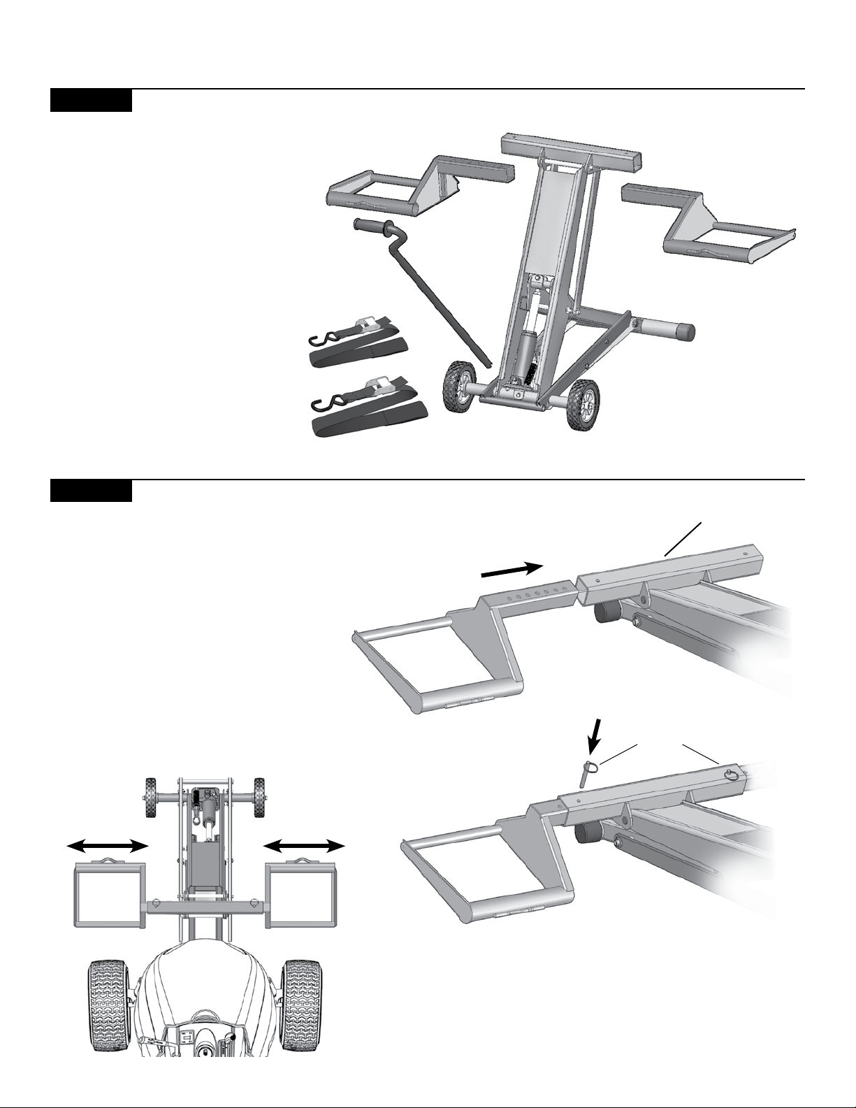
STEP 1
Remove lift from package.
Inventory items to be certain all
parts and hardware are present.
If you have any questions regarding
assembly, please call Customer
Service at 1-877-575-3173.
Identify the Right and Left Wheel
Pads.
IMPORTANT: The Wheel Pads are
side specic.
STEP 2
Slide the wheel pads into the T-Bar.
Line up the wheel pads to the front
tires of the mower.
The multiple holes allow for adequate
adjustment to t the front tires of the
mowers.
NOTE: Inside to outside wheel pad
expansion is 18.5”– 47.5”
T-Bar
Push Pin
Secure the wheel pads to the T-Bar with the Push Pins.
Make sure the Push Pins are securely inserted into the
holes.
NOTE: Wheel pads must be equal distance from the T-Bar
to maintain proper balance.
6
Page 7
ASSEMBLY AND OPERATING INSTRUCTIONS
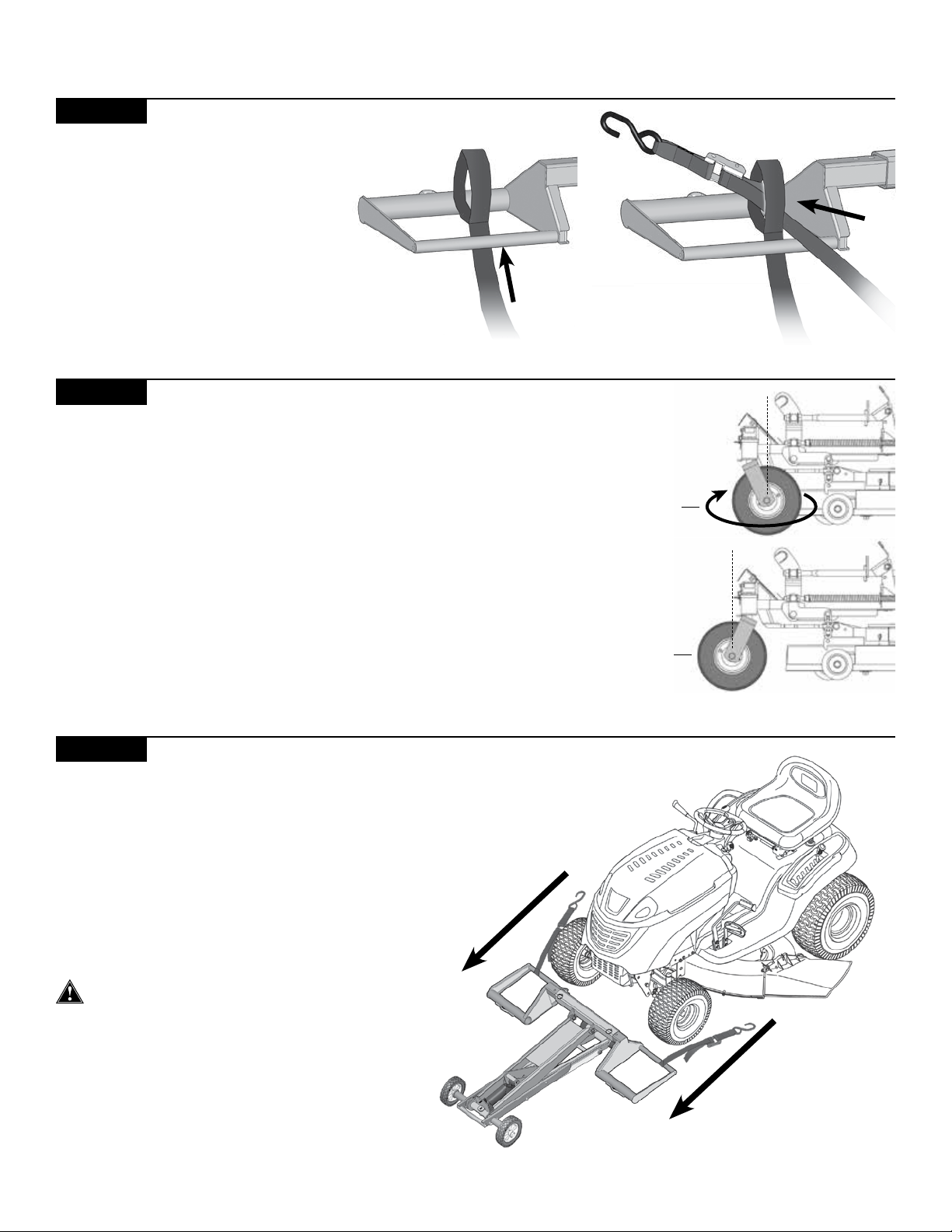
STEP 3
Attach the Safety Straps to the
wheel pads.
Insert the strap loop through the
wheel pad around the smaller
wheel pad tube. Thread strap hook
and buckle through the strap loop
and pull until tight. Repeat with the
other Safety Strap and wheel pad.
STEP 4
Reverse Front Tires of ZTR Mower (optional – if not applicable,
skip to Step 5)
In some cases, the mower deck or anti-scalping wheels will hit the
Lift Arm while the mower is being raised. This is often the case if
part of the deck (including the anti-scalping wheels) protrudes past
the center line of the front wheels of the mower. If this happens:
• Rotate the front tires 180° so that they are in the reverse position.
• Slide the lift as close to the wheels as possible.
STEP 5
Move the mower onto the Wheel Pads.
Wheel Pads must be properly aligned with
the mower’s front tires (see Step 2) and
secured with Push Pins.
NOTE: Wheel pads will accommodate
10”–17” tire sizes.
Forward
Wheel
Position
Reverse
Wheel
Position
Jack MUST be on a hard solid level surface.
NOTE: If the lift slides when moving the
mower onto the Wheel Pads, place Wheel
Chocks behind the lift’s wheels to
prevent it from sliding.
7
Page 8
ASSEMBLY AND OPERATING INSTRUCTIONS
STEP 6
Secure the front mower tires to the Wheel
Pads using the Safety Straps.
Extend the Safety Strap over the top of tire or
over the top of mower wheel arm and secure
the hook into the loop on the wheel pad.
Squeeze the metal buckle and pull end of
strap to tighten the Safety Straps over the top
of the tires to secure mower to Wheel Pads.
NOTE: Wheel Pads accommodate wheel
sizes from 10”–17” (25cm– 43cm).
NOTE: Inspect Safety Strap for wear before
each use.
Safety Strap
Wheel Pad
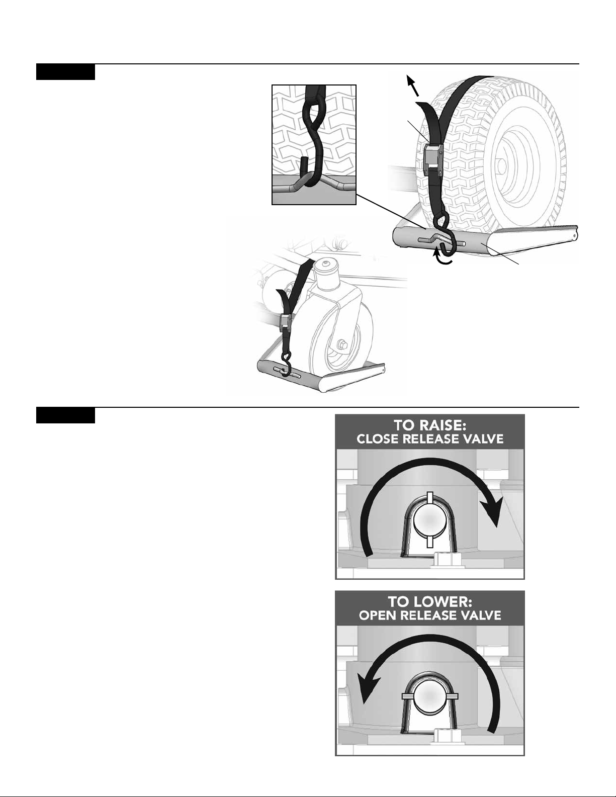
STEP 7
Operating the hydraulic cylinder.
To raise the lift: Close the release valve.
Turn Release Valve clockwise to CLOSE.
Rotate clockwise until the Release Valve stops
turning without effort. DO NOT over tighten
the Release Valve.
To lower the lift: Open the release valve.
Turn Release Valve counterclockwise to OPEN.
WARNING! Only requires 1/2 a turn before
pressure begins to release. DO NOT overturn
the Release Valve or the valve screw will come
out and spill hydraulic uid.
NOTE: Please refer to the Maintenance page
of this manual if hydraulic uid spills from the
cylinder.
8
Page 9

ASSEMBLY AND OPERATING INSTRUCTIONS
STEP 8
To raise the mower:
Make sure the cylinder valve is closed by turning
the valve clockwise.
If yes, proceed to insert the handle into the cylinder handle opening.
Proceed to pump the handle up and down to raise
the lift to the desired height. The cylinder will use
pumping action of the handle to raise the lift.
The automatic locking mechanism will engage at
three different lift heights.
The 3 locking positions are: 18”, 21”, 26”
As you pump the handle to raise the lift you will
hear a click sound at each of the locking positions
indicating the locking bar is fully secured.
See below diagram of the locking bar function.
NOTE: Make sure your mower is in neutral before
you raise your mower. The mower wheels need to
move freely as the mower raises.
LOCKED
When Locking Bar
Cover is parallel with
the Locking Bar, the
Locking Pin is LOCKED
in the Bar teeth.
Locking Bar
Cover
Locking Bar
Locking Pin
NOT LOCKED
When Locking Bar
Cover is raised or
angled with the Locking
Bar, the Locking Pin is
NOT LOCKED in the Bar
teeth.
Locking Bar
Locking Bar
Cover
Locking Pin
The automatic locking mechanism must be engaged
in one of the three lock position notches on the
Locking Bar before proceeding to service mower.
9
Page 10

ASSEMBLY AND OPERATING INSTRUCTIONS
STEP 9
Preparing the mower for service.
Place wheel chocks (not included) behind the back tires of the
mower and apply the parking brake on the mower.
YOU MAY NOW SERVICE THE MOWER.
STEP 10
To lower the mower:
1) Before Lowering the Lift, Remove the Wheel Chocks
and Parking Brake.
IMPORTANT WHEN LOWERING
MUST USE HANDLE TO OPERATE CYLINDER
2) Pump handle twice to release pressure from
locking position.
3) Step down on the Locking Bar with your foot, at the
same time, slowly turn the cylinder release valve with
the handle counterclockwise. Only 1/2 turn is required
to
release the pressure. Do not overturn the release valve.
Keep your foot on Locking Bar until it is completely
lowered or passed the last locking position.
Wheel Chock
x2
10
Page 11

MAINTENANCE
Important: Use only a good grade hydraulic jack oil. Avoid mixing different types of uid and NEVER use brake uid,
turbine oil, transmission uid, motor oil or glycerin. Improper uid can cause premature failure of the jack and the
potential for sudden and immediate loss of load.
HOW TO REPLACE THE HYDRAULIC CYLINDER
1) To remove the cylinder, remove the bolts holding the cylinder in place.
2) Remove old cylinder and install new cyclinder using the same hardware.
ADDING OIL TO HYDRUALIC CYLINDER
1) With saddle fully lowered and pump piston fully depressed,
set jack in its upright, level position. Remove oil ller plug.
2) Fill until oil is level with the ller plug hole, reinstall oil ller plug.
CHANGING OIL IN HYDRUALIC CYLINDER
For best performance and longest life, replace the complete
uid supply at least once per year.
1) With saddle fully lowered and pump piston fully depressed,
remove the oil ller plug.
2) Lay the jack on its side and drain the uid into a suitable container.
NOTE: Dispose of hydraulic uid in accordance with local regulations.
3) Fill with good quality jack oil. Reinstall oil ller plug.
Release
We recommend Mobil DTE 13 or equivalent.
LUBRICATION
1) A coating of light lubricating oil to pivot points, axles and hinges will help
to prevent rust and assure that wheels, casters and pump assemblies move freely.
2) Periodically check the pump piston and ram for signs of rust or corrosion.
Clean as needed and wipe with a clean, oil soaked rag.
NOTE: Never use sandpaper or abrasive material on these surfaces.
Extension
Screw
Filler
Plug
Piston
Assembly
Valve
Saddle
Ram
Socket
STORAGE
When not in use, store the Bottle Jack with pump piston and ram fully retracted.
TROUBLESHOOTING
Symptom Possible Causes Corrective Action
Jack will not lift load
Jack bleeds off after lift
Poor lift performance
Will not lift to full extension
• Check to make sure you are on a level surface.
Gravel is not considered a level surface.
• Make sure your parking brake is off on your
mower so it an roll as you are lifting.
• Release valve not tightly closed
• Overload condition
• Release valve not tightly closed
• Overload condition
• Hydraulic unit malfunction
• Fluid level low
• Air trapped in system
• Fluid level low
• Ensure release valve is tightly closed
• Remedy overload condition
• Ensure release valve is tightly closed
• Remedy overload condition
• Contact Customer Service
• Ensure proper uid level
• With ram fully retracted, remove oil ller
• Ensure proper uid level
plug to let pressurized air escape, reinstall
oil ller plug
11
Page 12

SUPPORTED TIRE SIZES
Wheel Pads accommodate wheel sizes from
10” – 17”
(25cm – 43cm)
12
Not for use with tires over 17” diameter (43cm) in size
Page 13

INTRODUCCIÓN
Este manual contiene instrucciones sobre
el ensamblaje, las piezas, el manejo, el
mantenimiento, el ajuste y la seguridad para el
elevador MoJack HDL.
ANTES DE UTILIZAR EL MOJACK HDL, LEA
DETENIDAMENTE ESTE MANUAL POR COMPLETO.
Al seguir las instrucciones de manejo, mantenimiento y
seguridad, prolongará la vida útil del elevador MoJack y
fomentará un manejo seguro.
Si necesita información adicional o si requiere de
un técnico capacitado en mantenimiento, póngase
en contacto con un vendedor odistribuidor
autorizado de equipos MoJack, obien llame al
1-877-575-3173.
Todas las piezas de MoJack se prueban y se
examinan minuciosamente antes de salir de la
fábrica a fin de garantizar que cumplen con las
normas de seguridad correspondientes.
NOTA: guarde el manual para consultas futuras.
NOTA: ubicación del número de serie
de la unidad.
¿Necesita ayuda?
NO devuelva este producto a la tienda.
Nuestro Departamento de atención al cliente está listo para ayudar.
1-877-575-3173
Envíe sus preguntas por Internet a:
www.theMoJack.com
N.° de patente: EE. UU., 8.448.920
© 2013 (MoJack Distributors, LLC)
MoJack y el logotipo de MoJack son marcas registradas de MoJack Distributors, LLC.
MoJack HDL es una marca comercial de MoJack Distributors, LLC. Todos los derechos reservados.
13
Page 14

ADVERTENCIAS E INSTRUCCIONES DE SEGURIDAD
Lea y comprenda todas las instrucciones de seguridad y manejo antes de utilizar el elevador para tractor cortacésped.
Nunca deje que utilice el elevador una persona que no esté familiarizada con las instrucciones de seguridad y manejo.
Siga todas las instrucciones de seguridad y mantenimiento provistas por el fabricante del tractor cortacésped antes de
utilizar el elevador.
No modifique el elevador de ninguna manera. Cualquier modificación hará nula toda garantía y podría comprometer su
seguridad personal.
Cuando utilice el elevador, mantenga a TODOS los espectadores alejados, a una distancia segura del elevador para tractor
cortacésped.
El elevador se debe utilizar en una superficie sólida y nivelada.
Solo debe elevar la parte DELANTERA del tractor cortacésped.
No levante las partes delantera y trasera del tractor cortacésped al mismo tiempo.
La parte delantera no debe superar la capacidad de elevación de 500 libras (226 kg) de peso. Si tiene una consulta respecto
del peso de su máquina, contáctese con MoJack al 1-877-575-3173.
Utilice el elevador únicamente para tractores cortacésped cuya parte delantera pese menos de 500 libras (226 kg) y que
calcen de manera adecuada en los soportes provistos para las ruedas (es decir, de 10" a 17" de diámetro y dentro de las
medidas interna y externa de la rueda de 18,5" a 47,5").
Los soportes para las ruedas deben estar a la misma distancia de la barra T a fin de mantener un equilibrio adecuado.
Detenga el motor y retire la llave siempre antes de comenzar cualquier tarea en el tractor cortacésped.
Siempre debe colocar topes para las ruedas (no incluidos) detrás de los neumáticos traseros del tractor cortacésped antes
de comenzar las tareas de mantenimiento. Para mayor seguridad, es posible aplicar el freno de estacionamiento después de
las llantas están en su lugar.
Nunca ponga en funcionamiento el motor al utilizar el elevador para tractor cortacésped.
No retire las advertencias o calcomanías de seguridad del elevador.
Asegúrese de que sea suficiente el espacio debajo del tractor cortacésped.
Asegúrese de que el tractor cortacésped esté lo suficientemente estable para trabajar.
Si no tiene en cuenta estas advertencias se pueden producir daños en los bienes y lesiones corporales graves o muerte.
IMPORTANTE: El uso del elevador está previsto para tractores cortacésped únicamente. La parte delantera no debe superar las
500 libras (226 kg) de peso. Nunca se debe utilizar para realizarle mantenimiento a otro tipo de maquinarias a menos que haya un
accesorio aprobado y apto para ese tipo de máquina.
14
Page 15

GARANTÍA Y DEVOLUCIONES
GARANTÍA LIMITADA
La garantía de MoJack cubre al producto por fallas en el material o la calidad, siempre y cuando se haya utilizado de manera debida,
durante dos años para uso residencial y un año para uso comercial. MoJack reemplazará toda pieza fallada sin costo alguno. Esta
garantía no cubre a los productos a los que se les hayan realizado modificaciones o ajustes, ni aquellos que se hayan sometido a un
mal uso o maltrato. ESTE ES EL ÚNICO RECURSO DEL CLIENTE. MOJACK NIEGA TODA GARANTÍA IMPLÍCITA, INCLUIDA LA
GARANTÍA DE COMERCIABILIDAD E IDONEIDAD PARA UN FIN DETERMINADO. MOJACK NO SERÁ RESPONSABLE POR DAÑOS
FORTUITOS O CONSECUENTES. ALGUNOS ESTADOS O PROVINCIAS NO PERMITEN LA EXCLUSIÓN NI LA LIMITACIÓN DE LAS
GARANTÍAS IMPLÍCITAS NI LOS RECURSOS POR EL INCUMPLIMIENTO DE DICHAS GARANTÍAS, POR LO QUE DICHAS
EXCLUSIONES PUEDEN NO SER PERTINENTES EN SU CASO. ESTA GARANTÍA LIMITADA LE BRINDA DERECHOS LEGALES
ESPECÍFICOS; ADEMÁS, PUEDE CONTAR CON OTROS DERECHOS QUE VARÍAN SEGÚN EL ESTADO O LA PROVINCIA.
¿Qué cubre esta garantía?
Esta garantía cubre a productos por fallas en el material o la calidad en un plazo de dos años a partir de la compra para uso
residencial y un año a partir de la compra para uso comercial.
¿Qué NO cubre esta garantía?
Esta garantía no cubre a gatos a los que se les han realizado modificaciones o ajustes de cualquier tipo con respecto al modelo
original. Tampoco cubrirá a gatos que hayan sufrido daños por mal uso, maltrato, accidente o negligencia. Esta garantía no cubre
daños fortuitos o consecuentes.
¿Cuál es el período de cobertura?
Estructura: 2 años por uso residencial. 1 año por uso comercial.
Cilindro hidráulico: 1 año.
¿Qué se hará para corregir los problemas?
Reemplazaremos toda pieza fallada (dentro del período de cobertura) sin costo.
¿Cómo puedo obtener un servicio de mantenimiento?
A fin de poder acceder al servicio de mantenimiento conforme a la presente garantía, DEBE registrar su gato en un plazo de treinta
(30) días a partir de la compra. Debe conservar su recibo como comprobante de la fecha de compra. Puede registrar su gato nuevo
en nuestro sitio web www.themojack.com o llamando a nuestra línea gratuita, 1-877-575-3173.
¿Cómo contacto a alguien para plantear una cuestión sobre la garantía?
Puede ponerse en contacto con MoJack a través de nuestra línea gratuita, 1-877-575-3173.
¿Cuento con otros derechos según la ley estatal?
Esta ley le brinda derechos legales específicos y además puede contar con otros derechos que varían según el estado.
¿Cuál es la política de devoluciones?
Por favor refiérase a la política y procedimientos de su lugar de compra para devoluciones y reembolsos de retorno.
15
Page 16

LISTA DE PIEZAS Y HERRAMIENTAS
ÍTEM
1
2
3
4
5
6
7
N.° DE PIEZA
518-0055
518-0030
518-0031
518-0032
518-0047
009-0007
001-0039
CANT.
1
1
1
1
1
2
2
DESCRIPCIÓN
Elevador para tractores cortacésped HDL
Cilindro hidráulico, 2 toneladas
Soporte para rueda izquierda
Soporte para rueda derecha
Palanca
Correas de seguridad
Clavijas a presión
T Barra
3
4
1
5
2
3 posiciones de bloqueo: 18”, 21”, 26”
FRENTE DE ELEVACIÓN
16
Correas de seguridad
6
Clavijas a presión
7
Page 17

INSTRUCCIONES DE ENSAMBLAJE Y DE MANEJO
PASO 1
Retire el elevador de la caja.
Haga un listado de todos los ítems
para asegurarse de que estén todas
las piezas y herramientas. Si tiene
dudas respecto del ensamblaje,
llame al Servicio de atención al
cliente al 1-877-575-3173.
Identifique los soportes para las
ruedas derecha e izquierda.
IMPORTANTE: no se puede
cambiar el lado del que va cada
soporte para las ruedas.
PASO 2
Deslice los soportes para las ruedas
para introducirlos en la barra T.
Alinee los soportes con los neumáticos
delanteros del tractor cortacésped.
La presencia de varios orificios permite un
ajuste adecuado para que encajen bien
los neumáticos delanteros de los tractores
cortacésped.
NOTA: la extensión del interior al exterior
del soporte para las ruedas es de 18,5" a
47,5".
T Barra
Clavija a presión
Fije los soportes para las ruedas a la barra T con las clavjas
a presión. Asegúrese de que las clavijas estén firmemente
introducidas en los orificios.
NOTA: los soportes para las ruedas deben estar a la misma
distancia de la barra T a fin de mantener un equilibrio adecuado.
17
Page 18

INSTRUCCIONES DE ENSAMBLAJE Y DE MANEJO
PASO 3
Sujete los soportes para las ruedas
con las correas de seguridad.
Introduzca el lazo de la correa por la
abertura metálica que se encuentra en
la parte delantera del soporte para las
ruedas. Pase el gancho de la correa y
deslícelo a través del lazo; tire hasta
ajustar. Repita el procedimiento con
la otra correa de seguridad y el otro
soporte para las ruedas.
PASO 4
Invierta las llantas delanteras de la podadora ZTR (opcional, si no
corresponde salte al Paso 5)
En algunos casos, la plataforma de la podadora o las ruedas a
prueba de fisuras golpearán el brazo de carga mientras se eleva la
podadora. Esto sucede frecuentemente si la parte delantera de la
plataforma (incluidas las ruedas a prueba de fisuras) sobresale y
pasa de la posición de las ruedas delanteras en la línea central de la
podadora. Si esto sucede:
Posición al
frente de la
rueda
• Gire 180° las ruedas delanteras, de modo que se encuentren en
posición invertida.
• Deslice el equipo ascensor lo más cerca posible de las ruedas.
PASO 5
Coloque el tractor cortacésped sobre los soportes
para las ruedas.
Los soportes deben estar bien alineados con los
neumáticos delanteros del tractor cortacésped (ver el
Paso 2) y fijos con las clavijas a presión.
NOTA: los soportes se adaptan a neumáticos de
10" a 17".
El gato DEBE estar en una supercie
sólida y nivelada.
Posición en
reversa de
la rueda
NOTA: Si las diapositivas de elevación,
coloque cuñas en las ruedas detrás de las
ruedas de la elevación para evitar que se
deslice.
18
Page 19

INSTRUCCIONES DE ENSAMBLAJE Y DE MANEJO
PASO 6
Fije los neumáticos delanteros del
tractor cortacésped a los soportes
para las ruedas, utilizando las
correas de seguridad.
Extienda la correa de seguridad por
encima del neumático o por encima
del brazo de la rueda del tractor
cortacésped y je el gancho en la
abertura del soporte para las ruedas.
Presione la hebilla metálica y tire del
extremo de la correa para ajustar las
correas de seguridad por encima de
los neumáticos y así jar el tractor
cortacésped a los soportes para las
ruedas.
NOTA: antes de cada uso, verique si la
correa de seguridad presenta desgaste.
Correa de seguridad
Soporte para
ruedas
PASO 7
Funcionamiento del cilindro hidráulico.
Para elevar el ascensor: Cierre la válvula de
liberación.
Gire la válvula de lanzamiento sentido horario
para cerrar. Gire hacia la derecha hasta la
válvula de liberación deja de girar sin esfuerzo.
NO apriete demasiado la válvula de liberación.
Para bajar el ascensor: Abra la válvula de
liberación.
Gire la válvula de salida izquierda para abrir.
ADVERTENCIA! Sólo requiere 1/2 giro antes
de presión comienza a liberar. NO gire demasiado válvula de escape o el tornillo de la válvula
va a salir y derramar líquido hidráulico.
NOTA: Por favor, consulte la página de Mantenimiento de este manual si los derrames de
uido hidráulico desde el cilindro.
PARA LEVANTAR:
VALVULA DE LIBERACIÓN CERRAR
BAJAR:
VALVULA DE LIBERACIÓN OPEN
19
Page 20

INSTRUCCIONES DE ENSAMBLAJE Y DE MANEJO
PASO 8
Eleve el tractor cortacésped.
Asegúrese de que la válvula del cilindro está
cerrada girando la válvula en sentido horario.
En caso afirmativo, proceder a insertar el mango
en la abertura del asa cilindro.
A continuación mueva la palanca hacia arriba
y hacia abajo para elevar el gato a la altura
deseada. El cilindro utilizará el movimiento de
bombeo de la palanca para elevar el gato.
El mecanismo de bloqueo automático se trabará
en tres alturas de elevación diferentes.
Las 3 posiciones de bloqueo son: 18", 21", 26"
A medida que pasa el mango para levantar el
ascensor se quiere escuchar un sonido de clic
en cada una de las posiciones de bloqueo lo que
indica la barra de bloqueo está completamente
asegurada.
Vea a continuación el diagrama de la función de
barra de bloqueo.
NOTA: asegúrese de que el tractor cortacésped
esté en punto muerto antes de elevarlo. Las
ruedas del tractor tienen que moverse libremente
a medida que el tractor asciende.
BLOQUEADO
Cuando Bloqueo de la
cubierta de la cuchilla es
paralelo a la lámina de
bloqueo, el Pasador está
encerrado en los dientes
de la lámina.
Bloqueo de la
cubierta de la lámina
Bloqueo de la lámina
Pasador de bloqueo
NO BLOQUEADO
Si el bloqueo de la cubierta de la lámina se eleva
o en ángulo con la Espada
de bloqueo, el Pasador
NO está encerrado en los
dientes de la lámina.
Bloqueo de la lámina
Bloqueo de la
cubierta de la lámina
Pasador de bloqueo
El mecanismo de bloqueo automático debe estar
fijo en una de las tres muescas de posición de la
barra de bloqueo antes de comenzar las tareas de
mantenimiento en el tractor cortacésped.
20
Page 21

INSTRUCCIONES DE ENSAMBLAJE Y DE MANEJO
PASO 9
Prepare el tractor cortacésped para realizar mantenimiento.
Coloque topes para las ruedas (no incluidos) detrás de los
neumáticos traseros del tractor cortacésped y accione el freno de
mano del tractor.
AHORA PUEDE REALIZAR LAS TAREAS DE MANTENIMIENTO
AL TRACTOR CORTACÉSPED.
PASO 10
Para bajar la segadora:
1) Antes de bajar el elevador, Retire las llantas y el freno
de mano.
IMPORTANTE PARA BAJAR MANGO DEBE
SER USADO PARA OPERAR CILINDRO
Tope para rueda
2) Bombee la manija dos veces para liberar la presión de
la posición de bloqueo.
3) Paso hacia abajo en la Barra de Seguridad con el pie,
al mismo tiempo, gire lentamente la válvula de escape
del cilindro con el mango hacia la izquierda. Mantenga
el pie en barra de cierre hasta que esté completamente
bajado o se pasa la última posición de bloqueo.
x
2
21
Page 22

MANTENIMIENTO
Importante: use únicamente un aceite de buena calidad para gatos hidráulicos. Evite mezclar diferentes tipos de líquidos y NUNCA
utilice líquido para frenos, aceite para turbinas, líquido para transmisiones, aceite para motores o glicerina. El líquido incorrecto puede
provocar la falla precipitada del gato y que potencialmente se pierda la carga de manera repentina e inmediata.
CÓMO REEMPLAZAR EL CILINDRO HIDRÁULICO
1) Para retirar el cilindro, extraiga los pernos que mantienen al cilindro en su lugar.
2) Retire el cilindro desgastado e instale el cilindro nuevo, usando las mismas
herramientas.
CÓMO AÑADIR ACEITE AL CILINDRO HIDRÁULICO
1) Con la montura totalmente baja y el pistón de la bomba completamente oprimido,
coloque el gato en posición perfectamente horizontal. Retire el tapón de llenado de
aceite.
2) Vierta aceite hasta que alcance el nivel del orificio del tapón de llenado y vuelva a
colocar el tapón de llenado.
CÓMO CAMBIAR EL ACEITE DEL CILINDRO HIDRÁULICO
Para un mejor rendimiento y una mayor vida útil, cambie el aceite por completo al
menos una vez por año.
1) Con la montura totalmente baja y el pistón de la bomba completamente oprimido,
retire el tapón de llenado de aceite.
2) Coloque la montura de costado y drene el aceite en un recipiente adecuado.
NOTA: Deseche el aceite del cilindro de acuerdo con los reglamentos locales.
3) Llene con aceite de buena calidad para gatos. Vuelva a colocar el tapón de
llenado de aceite. Recomendamos Mobil DTE 13 o equivalentes.
LUBRICACIÓN
1) Una capa de aceite lubricante liviano para los puntos de pivote, los ejes y las
bisagras contribuirá a evitar el óxido y asegurar que los conjuntos de las ruedas, las
rueditas y la bomba se muevan libremente.
2) Verifique periódicamente el ariete y el pistón de la bomba para detectar signos de
óxido o corrosión. Realice una limpieza según sea necesaria y pase un trapo limpio con aceite.
NOTA: Nunca use papel de lija u otro material abrasivo sobre estas superficies.
Extensión
Tornillo
Relleno
Enchufe
Pistón
Asamblea
Lanza-
miento
Válvula
Sillín
Pisón
Enchufe
ALMACENAMIENTO
Cuando no esté en uso, guarde el ascensor en la posición completa bajado.
RESOLUCIÓN DE PROBLEMAS
Indicio
El gato no eleva la carga
El gato se purga después
de la elevación
Bajo rendimiento del
elevador
No eleva al máximo
Posibles causas
• La válvula de alivio no está
bien cerrada
• Estado de sobrecarga
• La válvula de alivio no está
bien cerrada
• Estado de sobrecarga
• Mal funcionamiento de la
unidad hidráulica
• Bajo nivel de líquido
• Aire atrapado en el sistema
• Bajo nivel de líquido
• Asegúrese de que la válvula de alivio esté bien cerrada
• Disminuya la sobrecarga
• Asegúrese de que la válvula de alivio esté bien cerrada
• Disminuya la sobrecarga
• Contáctese con el Servicio de atención al cliente de MoJack
• Asegúrese de que haya un nivel adecuado de líquido
• Una vez que el ariete esté completamente retraído, retire el
tapón de llenado de aceite para que salga el aire presurizado.
Vuelva a colocar el tapón de llenado
• Asegúrese de que haya un nivel adecuado de líquido
Acción correctiva
22
Page 23

MEDIDAS DE NEUMÁTICOS ADMITIDAS
Los soportes para ruedas se adaptan a neumáticos de
10" – 17"
(25 cm–43 cm)
No lo utilice con neumáticos cuyo diámetro sea mayor a 17" (43 cm).
23
Page 24

V092116
 Loading...