

Page 1
Instructions for Assembly and Operation
Instrucciones para Asamblea y de la Operación
www.theMoJack.com
1-877-575-3173
Ver. 092418
Page 2
MoJack 750XT Lift
Introduction
This manual contains assembly, parts, operating,
maintenance, adjustment and safety instructions for
your MoJack 750XT lift.
BEFORE USING YOUR MOJACK 750XT, CAREFULLY
READ THIS MANUAL IN ITS ENTIRETY.
By following these operating, maintenance and safety
instructions, you will prolong the life of your MoJack lift
and promote safe operation.
All MoJack parts are thoroughly tested and inspected
before leaving the factory to ensure that they comply
with all relevant safety standards.
Need
Assistance?
Please DO NOT return this
product to the store.
Our Customer Service
Department is ready to help!
1-877-575-3173
NOTE: Please save this manual for future reference.
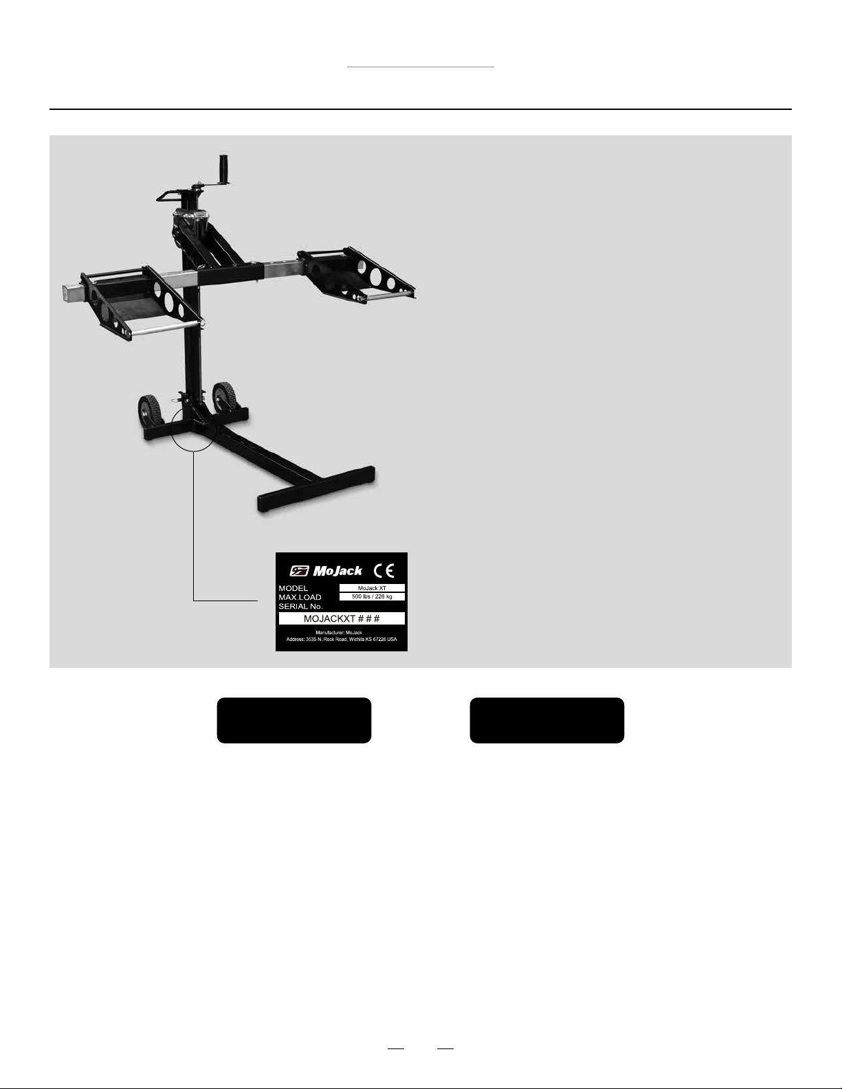
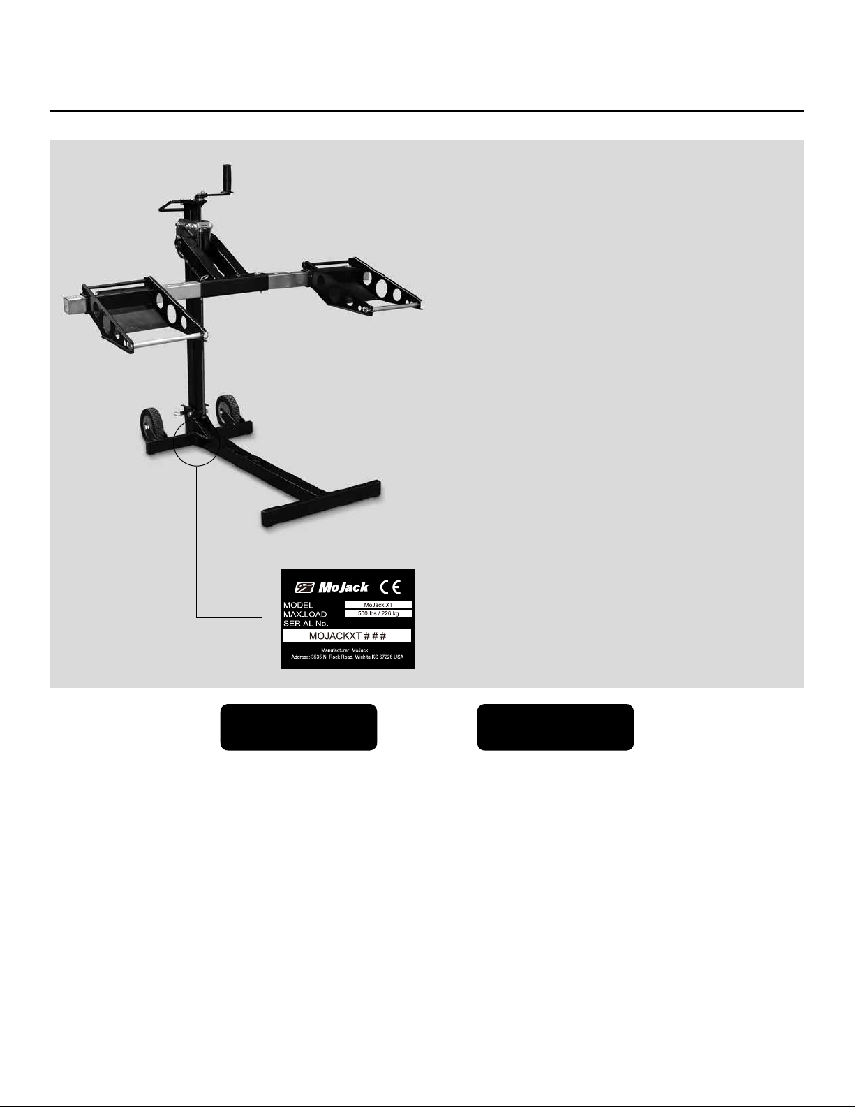
NOTE: Location of unit Serial Number.
¿Necesita
ayuda?
¡NO devuelva este producto
a la tienda!
¡Nuestro Departamento de
Servicio de Atención al Cliente
está listo para ayudarle!
1-877-575-3173
Submit your questions online at:
Envie sus preguntas por Internet a:
www.theMoJack.com
Patent #s: U.S., 8,448,920 and 8,387,953
MoJack and the MoJack logo are registered trademarks of MoJack Distributors, LLC.
MoJack 750XT is a trademark of MoJack Distributors, LLC. All rights reserved.
© 2014 MoJack Distributors, LLC.
2
Page 3
MoJack 750XT Lift
Warnings and Safety Instructions
Read and understand all safety and operating instructions before using the MoJack 750XT.
Never allow anyone unfamiliar with the safety or operating instructions to use the MoJack 750XT.
Follow all safety and servicing instructions provided by the lawn mower’s manufacturer before using
the MoJack 750XT.
Do not modify the MoJack 750XT in any way. Any modications will void any and all warranties and could
compromise your personal safety.
When using the MoJack 750XT, keep ALL bystanders at a safe distance away from the MoJack 750XT.
The MoJack 750XT must be used on a solid level surface.
Do not lift the front end and the back end of the mower at the same time.
Do not use MoJack 750XT lift for anything other than a mower, unless the proper accessory is used.
Always stop engine and remove key before beginning any work on the mower.
Never operate the mower’s engine while using the MoJack 750XT.
Do not exceed the lifting capacity of 750 lbs.
If the MoJack 750XT Tower is leaning while lifting or lowering the mower, this indicates an overload
condition. Remove the mower immediately.
Tower must be locked in place with the Tower Locking Pin before using the MoJack 750XT.
Carrier Locking Pin must be locked into Tower before starting any service on mower.
Do not remove safety warnings or decals from MoJack 750XT.
Before each use, always check for any worn, loose or damaged parts on the MoJack 750XT. If any
damaged parts are present, do not use the MoJack 750XT and contact MoJack at 1-877-575-3173.
Do not climb on mower while it is lifted, being lifted or being lowered.
No one should be on the mower while it is lifted, being lifted or being lowered.
After the mower is raised to a working height, always place wheel chocks (not included) behind the back tires
of the mower.
Wheel Pads must be equal distance from the Lift Arm to maintain proper balance.
Remove all mower attachments before using the MoJack 750XT.
Failure to follow these warnings may result in property damage and serious bodily injury or death.
IMPORTANT: The MoJack 750XT is intended for use with riding lawn mowers and riding lawn tractors only. Do not
exceed 750 lbs. It should never be used to service other types of machinery unless there is an approved MoJack
accessory tted for the type of machinery. Please consult you local MoJack dealer or distributor.
3
Page 4

MoJack 750XT Lift
Warranty and Returns
LIMITED WARRANTY
For two years for residential use and one year for commercial use MoJack warrants the product against failure due to
defect in material or workmanship when product is used properly. MoJack will replace any defective part at no cost.
This warranty does not cover any product that has been altered or adjusted, or any product that has been misused or
abused. THIS IS THE CUSTOMER’S SOLE AND EXCLUSIVE REMEDY. MOJACK DISCLAIMS ALL IMPLIED WARRANTIES, INCLUDING THE WARRANTY OF MERCHANTABILITY AND FITNESS FOR A PARTICULAR PURPOSE. MOJACK
SHALL NOT BE LIABLE FOR ANY INCIDENTIAL OR CONSEQUENTIAL DAMAGES. SOME STATES OR PROVINCES DO
NOT ALLOW THE EXCLUSION OR LIMITATION OF THE IMPLIED WARRANTIES OR THE REMEDIES FOR BREACH OF
THE IMPLIED WARRANTIES, SO THESE EXCLUSIONS MAY NOT APPLY TO YOU. THIS LIMITED WARRANTY GIVES
YOU SPECIFIC LEGAL RIGHTS, AND YOU MAY ALSO HAVE OTHER RIGHTS WHICH VARY FROM STATE TO STATE
OR PROVINCE TO PROVINCE.
What does this warranty cover?
This warranty covers against a failure due to a defect in material or workmanship within two years of purchase for
residential use and within one year of purchase for commercial use.
What does this warranty NOT cover?
This warranty does not cover any MoJack which has been altered or adjusted in any way from its original model.
It will not cover any MoJack which has been damaged due to misuse, abuse, accident or negligence. This warranty does
not cover incidental or consequential damages.
What is the period of coverage?
Two-year warranty for residential use, one-year for commercial use from date of purchase for the original owner.
What will MoJack do to correct problems?
We will replace any defective part (within the coverage period) at no charge.
How can I get service?
In order to be eligible for service under this warranty you MUST register your MoJack within thirty (30) days of
purchasing. You must keep your receipt as proof of date of sale. You can register your new MoJack on our website at
www.themojack.com or by calling our toll-free number 1-877-575-3173.
How do I contact MoJack about a warranty issue?
You can contact us from our website at www.themojack.com or by calling our toll-free number 1-877-575-3173.
Do I have other rights under State Law?
This warranty gives you specic legal rights, and you may also have other rights which vary from state to state.
What is the return policy?
Please refer to the Return Policy and Procedures of your place of purchase for returns and refunds.
How do I contact MoJack?
You can call our toll-free number 1-877-575-3173 or by email at [email protected].
4
Page 5
MoJack 750XT Lift
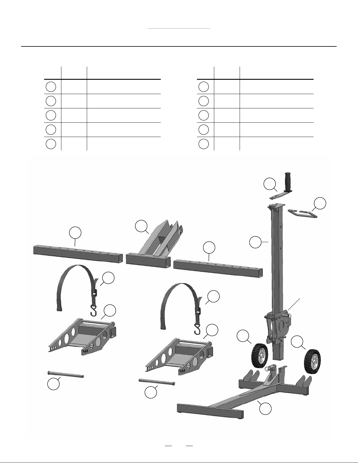
Parts List
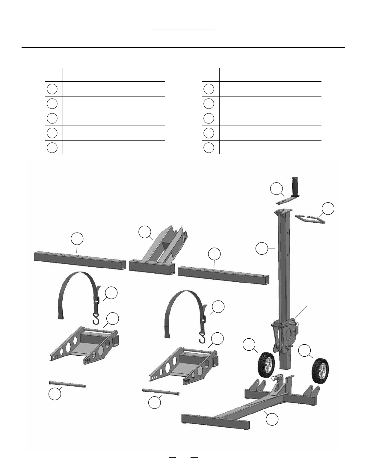
Item
No.
1
2
3
4
5
Qty.
1
1
1
2
2
6
Description
Tower
Lift Arm
Base
Wheel
Wheel Pads
Item
No.
6
7
8
9
10
Qty.
2
1
1
2
2
Description
Lift Arm Inserts
Grip Handle
Crank Handle
Support Rod
Safety Strap
8
7
2
1
6
10
10
Carrier
5
5
4
4
9
9
3
5
Page 6
MoJack 750XT Lift
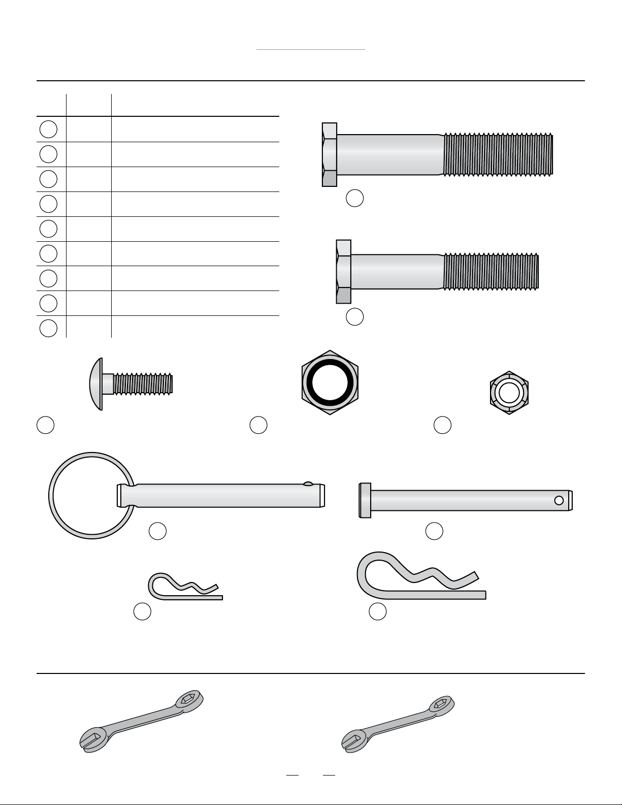
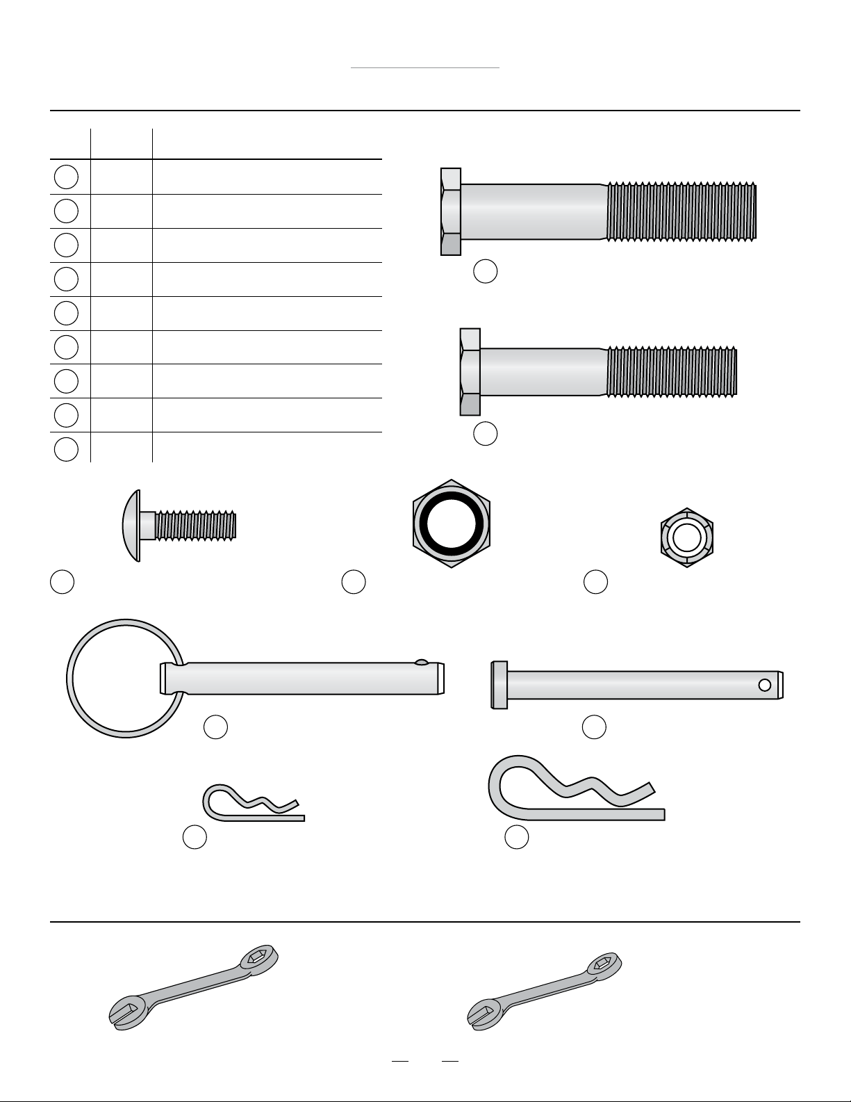
Hardware List
Item
No.
11
12
13
14
15
16
17
18
19
Qty.
1
2
3
3
3
4
1
1
2
Description
Cap Screw M12-1.75 X 80
Cap Screw M12-1.75 X 65
Carriage Bolt M8-1.25 X 20
Nylock Nut – M12-1.75
Nylock Nut – M8-1.25
Push Pin
Clevis Pin
Small Hair Pin
Large Hair Pin
11
Cap Screw M12-1.75 X 80
12
Cap Screw M12-1.75 X 65
13
Carriage Bolt M8-1.25 X 20
16
Push Pin
18
Small Hair Pin
14
Nylock Nut – M12-1.75
19
Large Hair Pin
Tools Needed for Assembly
15
Nylock Nut – M8-1.25
17
Clevis Pin
19mm Wrench (2) 13mm Wrench (1)
6
Page 7
Assembly Instructions
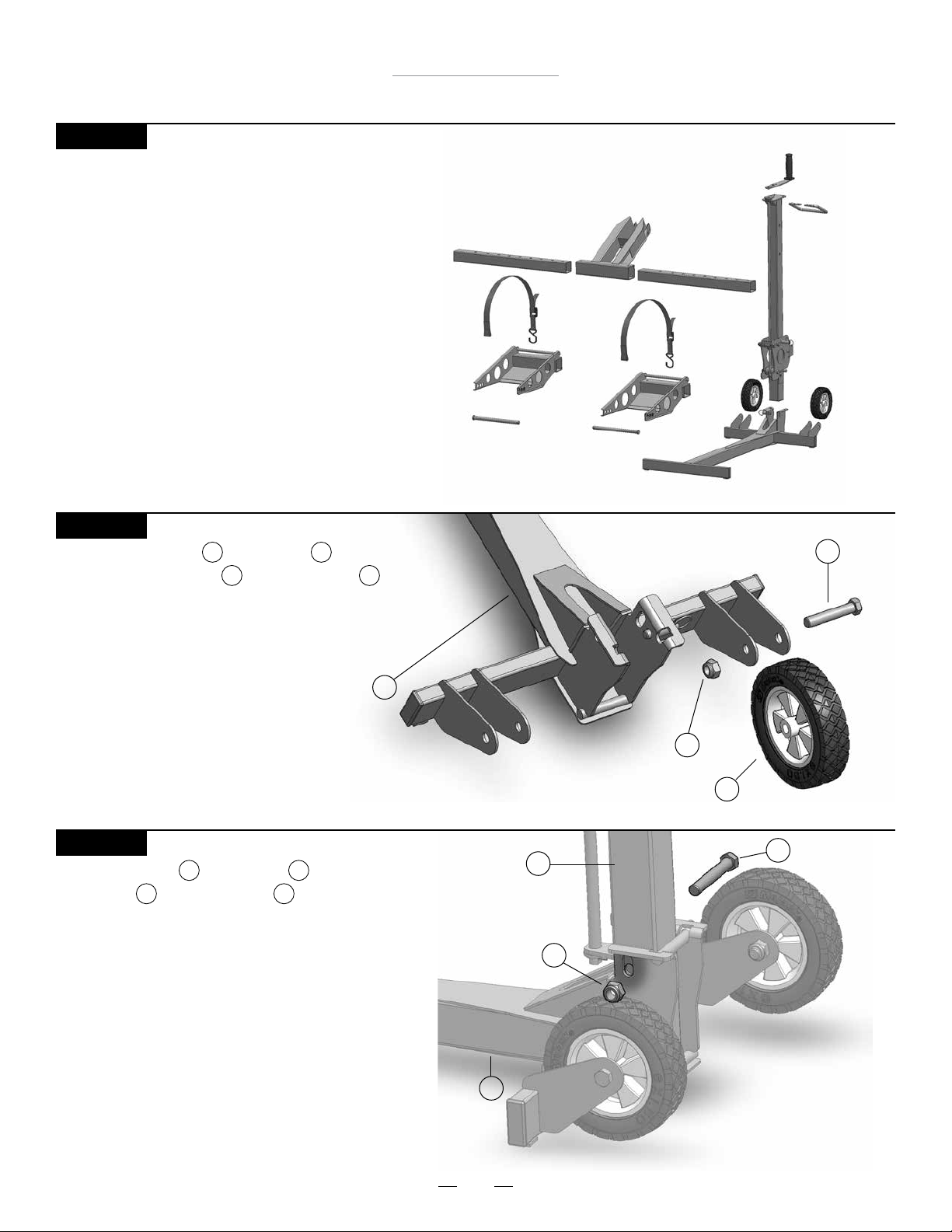
STEP 1
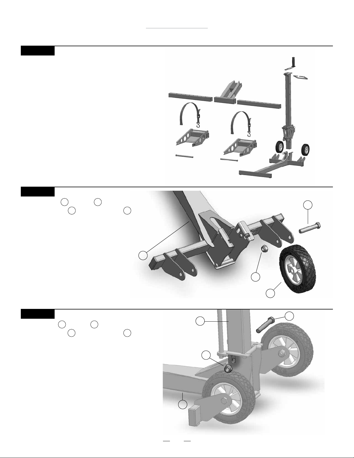
Remove MoJack 750XT from package.
Check to be certain all parts and hardware
are present. If any parts or hardware are missing,
please contact MoJack at 1-877-575-3173 or
email us at [email protected].
MoJack 750XT Lift
STEP 2
Assemble the Wheel to the Base
by inserting Cap Screw and Nylock Nut
and tighten. Repeat with second Wheel.
Note: Do not over tighten Nylock Nut.
STEP 3
Attach the Tower to the Base using
Cap Screw and Nylock Nut as shown.
Note: Do not over tighten Nylock Nut.
11 14
4 3
12 14
Base
1 3
Cap Screw
3
Tower
Nylock Nut
Nylock Nut
1
14
14
Wheel
4
11
12
Cap Screw
Base
3
7
Page 8
STEP 4
MoJack 750XT Lift
Assembly Instructions
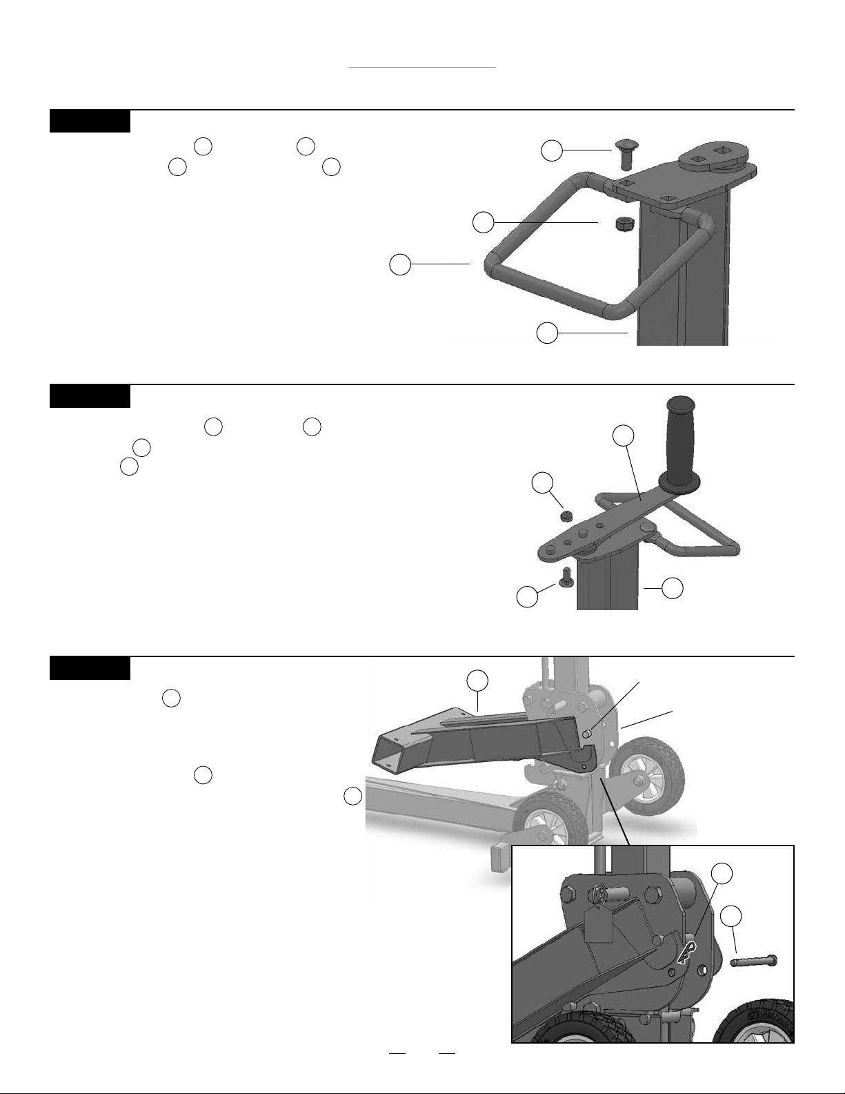
Attach the Grip Handle to the Tower with
two Carriage Bolts and two Nylock Nuts .
7 1
13 15
Nylock Nut
Grip Handle
7
STEP 5
Attach the Crank Handle to the Tower by inserting
Carriage Bolt with threads facing up and fasten with
Nylock Nut .
13
15
18
Note: There are two holes in the Crank Handle. The hole
closest to the rubber grip will provide a 6” radius for cranking. The other hole will provide an 8” radius, making cranking easier. Use the hole that works best with your model of
lawn mower.
Carriage Bolt
15
Tower
Nylock Nut
Carriage Bolt
13
1
Crank Handle
15
13
8
Tower
1
STEP 6
Hang the Lift Arm on the Carrier by hooking
2
the slotted area of the Lift Arm under the top bar
of the Carrier. Lift Arm must be inserted from the
front and then lowered which fastens Lift Arm into
place. Insert Clevis Pin through the hole in the
Carrier and lock by fastening the Small Hair Pin
17
18
to the Clevis Pin.
Lift Arm
8
2
Top Bar of Carrier
Carrier
Small
18
Hair Pin
Clevis
17
Pin
Page 9
MoJack 750XT Lift
Assembly Instructions
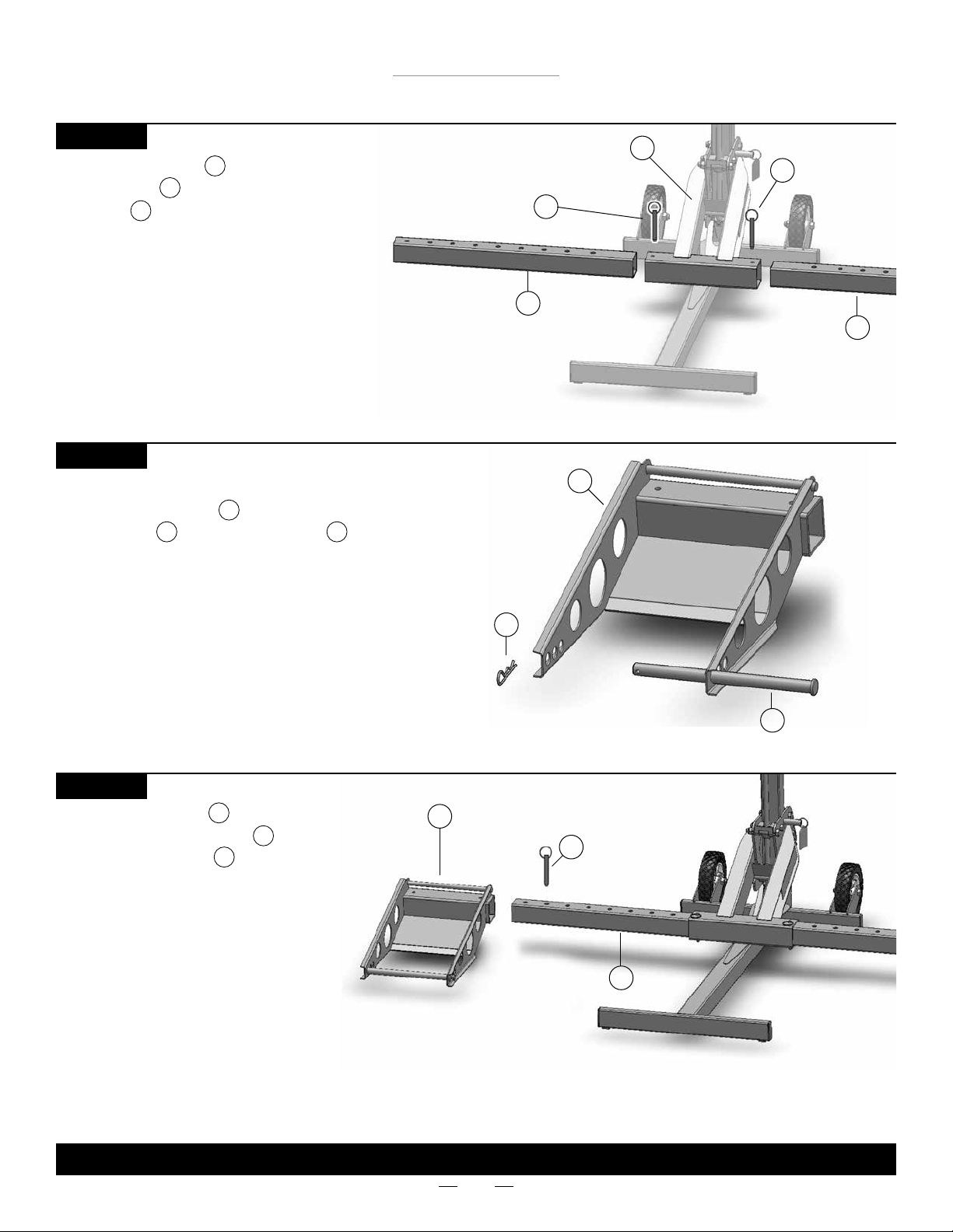
STEP 7
Slide Lift Arm Inserts into both sides
of the Lift Arm and secure with
Push Pins as shown.
16
6
2
STEP 8
Ready the Wheel Pads for installation by adding
Support Rods and Large Hair Pins .
11 19
5
Push Pin
Lift Arm Insert
Wheel Pad
Lift Arm
2
Push Pin
16
16
6
Lift Arm Insert
6
5
STEP 9
Slide the Wheel Pads onto both
sides of the Lift Arm Inserts and
secure with Push Pins .
5
6
16
Note: The Wheel Pads can be moved in
or out to t different mower widths. Use
the conguration that works best with
your model of lawn mower. The Wheel
Pads must be equal distance from the
Lift Arm to maintain proper balance.
Large Hair Pin
Wheel Pad
5
19
16
Lift Arm Insert
Push Pin
6
Support Rod
11
THIS COMPLETES ASSEMBLY.
9
Page 10
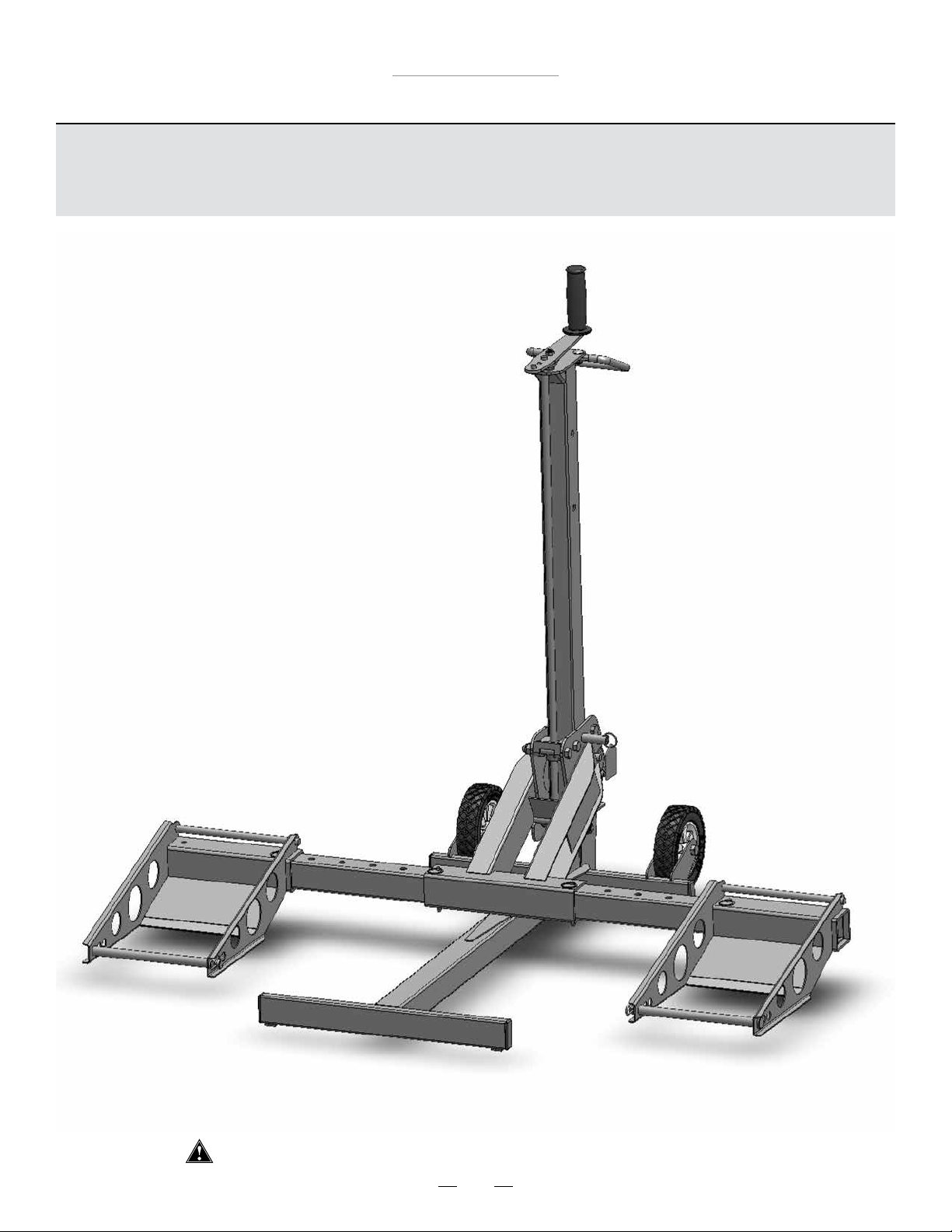
MoJack 750XT Lift
Operating Instructions
Some steps of the Operating Instructions are repeated from the
Assembly Instructions. The Operating Instructions will show a full
working cycle of the MoJack 750XT.
Before using the MoJack 750XT, carefully read this manual in its entirety.
10
Page 11
MoJack 750XT Lift
Operating Instructions
Preparing the MoJack 750XT for Use (Steps 1 - 8)
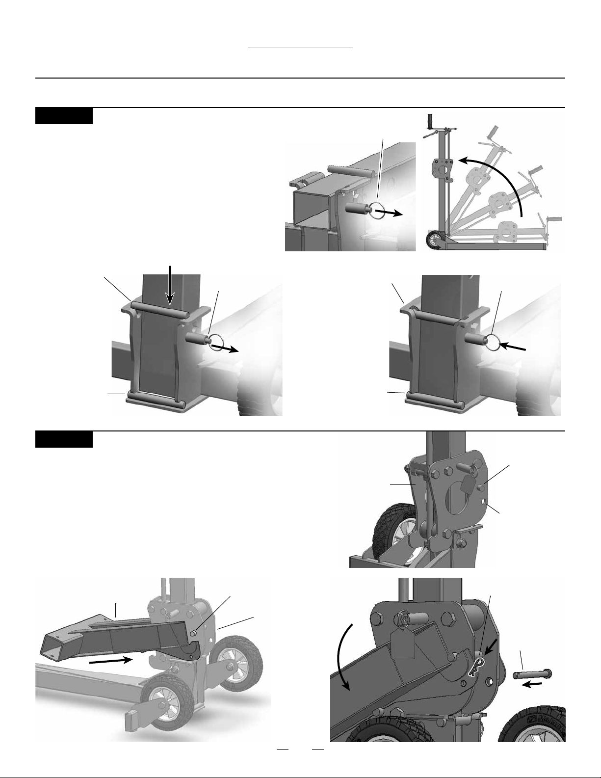
STEP 1
Unfolding MoJack 750XT
• Pull locking pin out to unlock.
• Raise the Tower by pulling up on the Grip Handle.
Once the Tower is in the vertical position, lift up on
the Grip Handle and drop the Tower into the Base.
• The tower will be securely locked in place when the
locking pin retracts and the tower is snug in the
channel behind the crossbar.
Drop Tower into Base
Crossbar
When Tower is
above the bar,
unit is NOT
locked and
UNSECURE.
Tower Locking Pin
(unlocked position)
Tower Locking Pin
(unlocked position)
Crossbar in
channel
When Tower sits
behind the bar,
unit is locked
and
fully secure.
Tower Locking
Pin
(locked position)
STEP 2
Installing Lift Arm
• Hang the Lift Arm on the Carrier by hooking the slotted area
of the lift Arm under the top bar of the Carrier. Lift Arm must
be inserted from the front and then lowered which fastens
Lift Arm into place.
• Secure Lift Arm to Carrier with Clevis Pin and Small Hair Pin.
Lift Arm
Top Bar of Carrier
Carrier
Top Bar
Carrier
Clevis Pin
hole
Small Hair Pin
Clevis Pin
11
Page 12
MoJack 750XT Lift
Operating Instructions
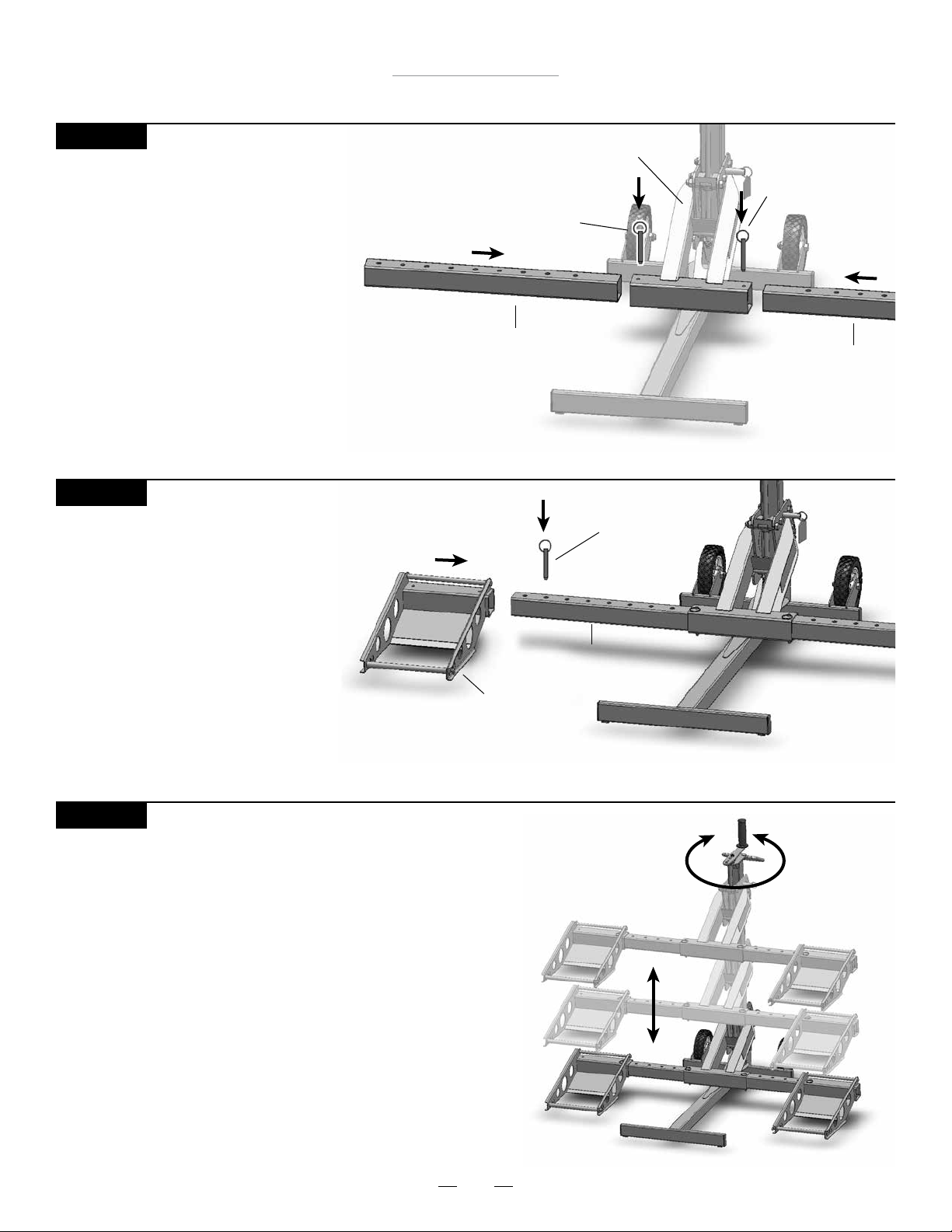
STEP 3
Installing Lift Arm Inserts
• Slide Lift Arm Inserts into both sides of the
Lift Arm and secure with Push Pins.
STEP 4
Installing Wheel Pads
• Slide Wheel Pads onto Lift Arm Inserts and
temporarily secure with Push Pins.
Lift Arm
Push Pin
Push Pin
Lift Arm Insert
Lift Arm Insert
Push Pin
Wheel Pad
STEP 5
Familiarize Yourself with the MoJack 750XT
• Practice raising and lowering the Lift Arm before attempting to
lift the mower (see Steps 12 – 16 on how to raise and lower
the Lift Arm).
• Practice Step 21 if you intend to raise or lower the mower with
a drill attachment.
Lift Arm Insert
12
Page 13
MoJack 750XT Lift
Operating Instructions
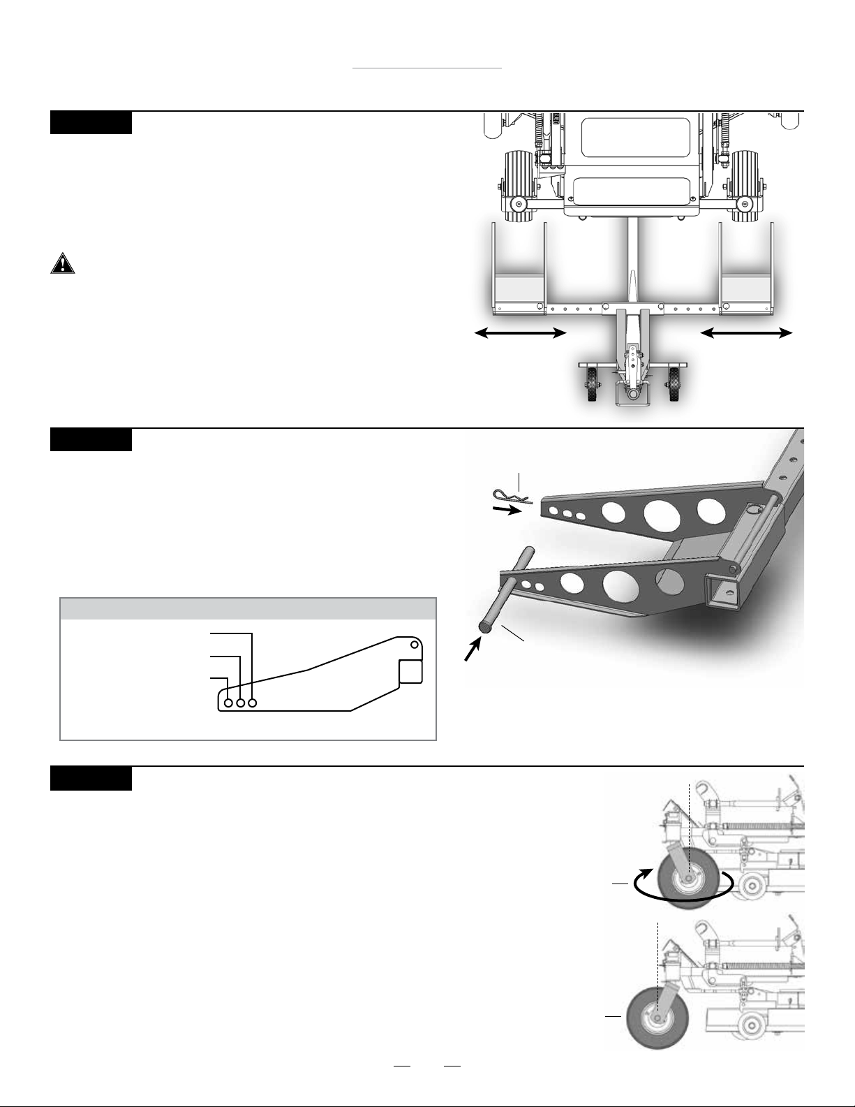
STEP 6
Aligning Wheel Pads to Fit Mower
• Place the front tires of mower 6” in front of the Wheel Pads.
• Remove Push Pins and align the Wheel Pads so that the front
mower tires will be centered on the Wheel Pads.
• Replace the Push Pins to lock the Wheel Pads to the Lift Arm.
Wheel Pads must be equal distance from the Lift Arm to
maintain proper balance.
STEP 7
Adjusting Support Rods for Proper Tire Size
• Adjust Support Rods on Wheel Pads to accommodate the
front tire size of the mower. Please refer to the chart below
for proper Support Rod placement based on the diameter
of the mower’s front tires.
• Secure Support Rods to Wheel Pads with Large Hair Pins.
SUPPORT ROD GUIDE FOR TIRE SIZES
10” - 11.5” (25cm - 29cm)
12” - 15” (30cm - 38cm)
15.5” - 17” (39cm - 44cm)
See page 20 for more more detailed guide.
STEP 8
Reverse Front Tires of Mower (optional – if not applicable, skip to Step 9)
• In some cases, the mower deck or anti-scalping wheels will hit the
Lift Arm while the mower is being raised. This is often the case if
part of the deck (including the anti-scalping wheels) protrudes past
the center line of the front wheels of the mower.
• Rotate the front tires 180° so that they are in the reverse position.
• Remove the Support Rods from the Wheel Pads and slide the
MoJack 750XT underneath the mower.
• Secure the Support Rods to Wheel Pads with Large Hair Pins.
Large Hair Pin
Support Rod
Forward
Wheel
Position
13
Reverse
Wheel
Position
Page 14
MoJack 750XT Lift
Operating Instructions
Using the MoJack 750XT (Steps 9 - 16)
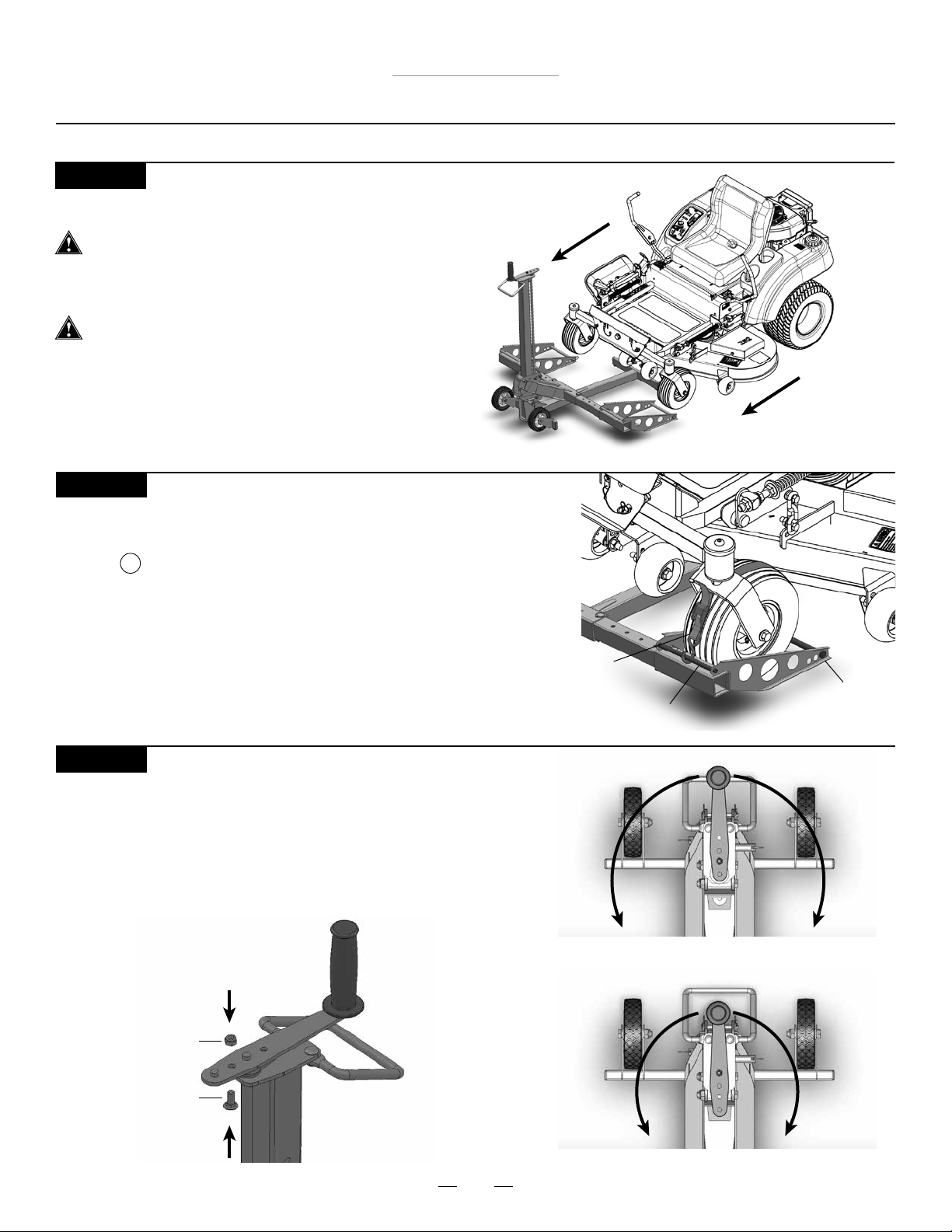
STEP 9
Move Mower onto MoJack 750XT
The MoJack 750XT must be used on a solid
level surface.
• Drive or roll the mower onto the Wheel Pads.
Stop engine and remove the key.
STEP 10
Strapping Front Mower Tires to Wheel Pads
• Secure the front mower tires to the Wheel Pads using the Safety
Straps . Secure the hook on the Safety Strap to the Wheel Pad Cross
Bar and insert the Support Rod into the loop on the Safety Strap by detaching the Support Rod and then sliding the Safety
Strap Loop through and reattaching the Support Rod.
• Tighten the Safety Straps over the top of the tires
to secure mower to Wheel Pads.
STEP 11
Adjusting the Crank Handle (optional)
• The optimal Crank Handle length is in the longer setting. Some
mowers have brush guards or larger hoods that interfere with
the longer Crank Handle. The Crank Handle can be adjusted by
removing the Nylock Nut and Carriage Bolt and re-attaching in
the shorter setting.
10
Safety Strap
Wheel Pad Cross Bar
Support Rod
Longer Setting – 8” Radius
Nylock Nut
Carriage Bolt
Shorter Setting – 6” Radius
14
Page 15
MoJack 750XT Lift
Operating Instructions
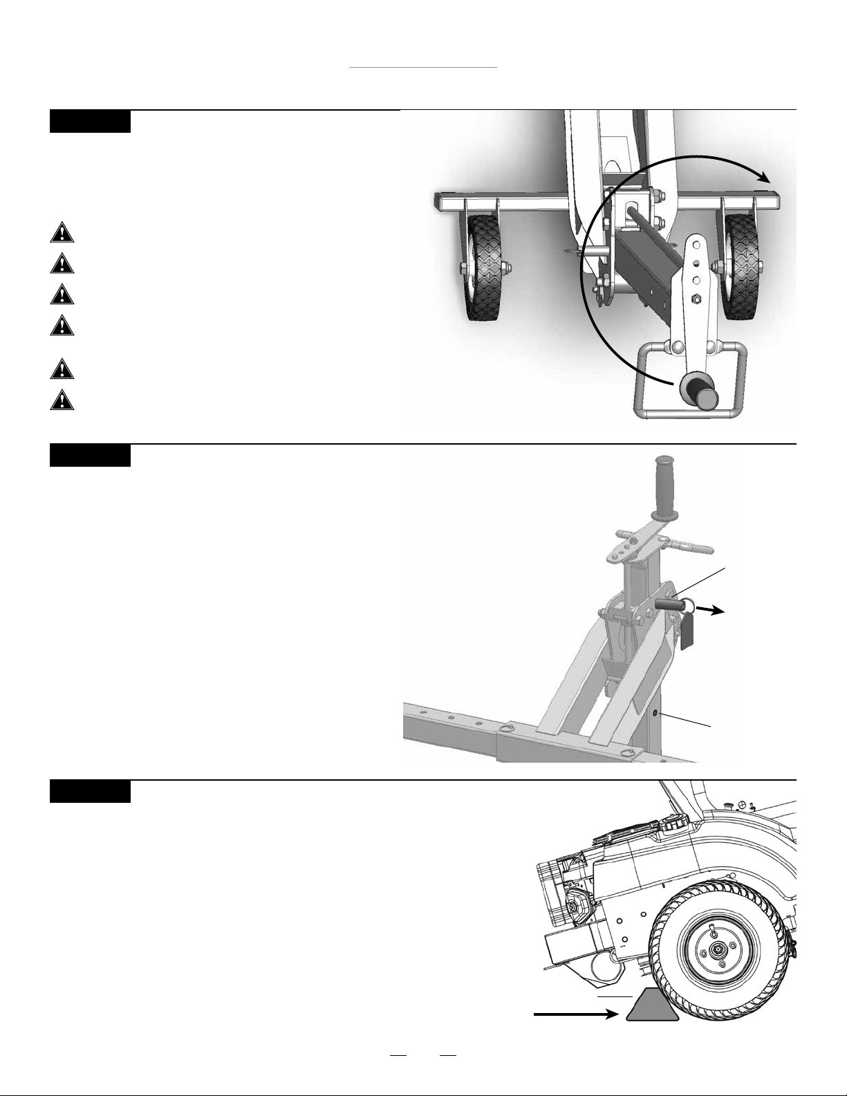
STEP 12
Raising the Mower
• Raise the mower by rotating the Crank Handle clockwise.
• See Step 22 for raising the mower with drill attachment.
Do not attempt to lift more than 750 lbs.
The MoJack 750XT must be used on a solid level surface.
The engine must be turned off and key removed.
The mower must be in neutral.
Disengage transmission if neccessary.
The parking brake must be off during this step.
The Safety Straps must be rmly tightened.
STEP 13
Raising Lift Arm to Locking Position
• Raise the Lift Arm until the Carrier Locking Pin drops into the
Safety Hole.
• The Carrier Locking Pin automatically drops into the Safety Holes as
the Carrier passes the Safety Holes on the Tower when raising.
• Note: When lowering the Lift Arm, the Carrier Locking Pin
must be held out by the operator until it clears the bottom
Safety Hole.
STEP 14
Preparing the Mower for Service
• Place wheel chocks (not included) behind the back tires of the mower.
• Now apply the parking brake on the mower.
• The Carrier Locking Pin must be locked into one of the two
Safety Holes.
Carrier
Locking
Pin
Pull Out
to
Unlock
and
Lower
Safety Hole
15
Wheel Chock
Page 16
Operating Instructions
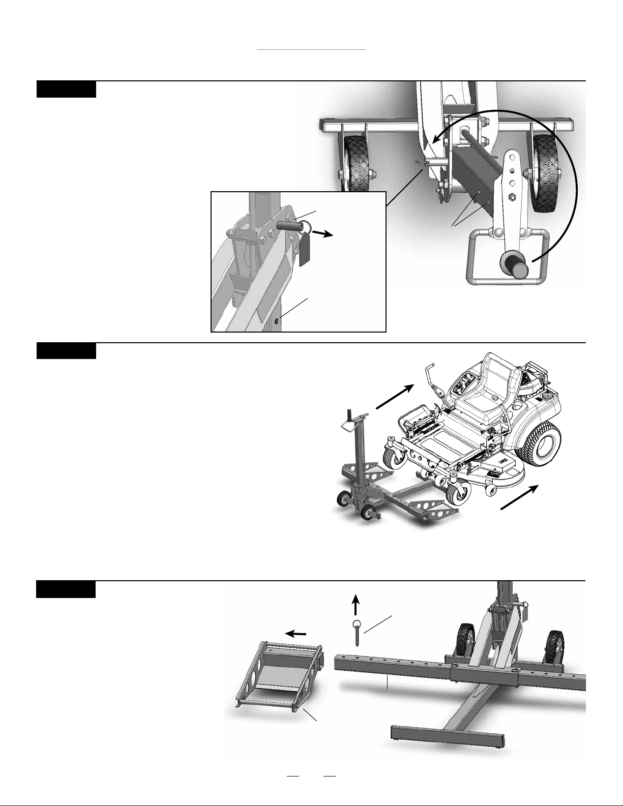
STEP 15
Lowering the Mower
• Remove wheel chocks.
• Release the parking brake.
• Mower must be in neutral.
Disengage transmission if neccessary.
• Pull and hold the Carrier Locking Pin
out and turn the Crank Handle
counter clockwise until
Wheel Pads are rmly on
the ground. The Carrier
Locking Pin must be pulled
out until it clears the bottom
Safety Hole. Do not force the
handle past the lock point,
as this may damage the
Screw Thread.
MoJack 750XT Lift
Carrier
Locking
Pin
Safety Holes
Pull Out
to Unlock
and Lower
Safety Hole
STEP 16
Removing the Mower from the MoJack 750XT
• Remove the Safety Straps from front mower tires.
• Removing Support Rods is optional during this step.
• Drive or roll the mower off of the Wheel Pads.
Preparing the MoJack 750XT for Storage (Steps 17 - 20)
STEP 17
Removing the Wheel Pads
• Remove Wheel Pad Push Pins
and pull Wheel Pads out from
the Lift Arm Inserts.
• Store the Push Pins in the
Wheel Pads.
Push Pin
Lift Arm Insert
Wheel Pad
16
Page 17
MoJack 750XT Lift
Operating Instructions
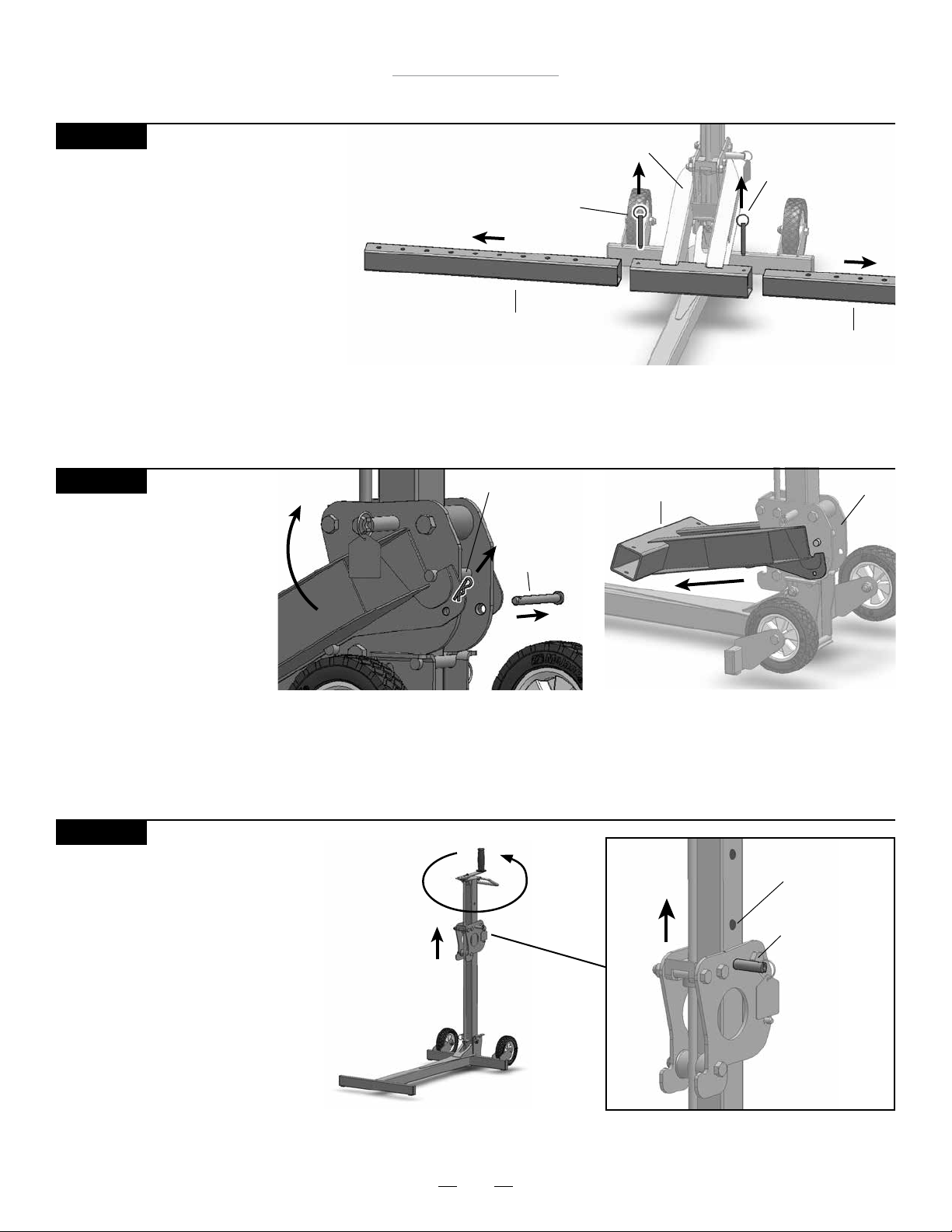
STEP 18
Removing LIft Arm Inserts
• Remove Lift Arm Push Pins and pull
Lift Arm Inserts from the Lift Arm.
• Store the Push Pins in the Lift Arm.
STEP 19
Unhooking the Lift Arm
• Remove Small Hair Pin
and Clevis Pin from Lift Arm.
• Unhook the Lift Arm from
the Carrier.
• Store the Small Hair Pin
and Clevis Pin in the
Lift Arm.
Push Pin
Lift Arm Insert
Small Hair Pin
Clevis Pin
Lift Arm
Lift Arm
Push Pin
Lift Arm Insert
Carrier
STEP 20
Raise Carrier
• Raise the Carrier by turning the
Crank Handle clockwise until
the Carrier Locking Pin drops
into the safety hole.
Safety Hole
Carrier
Locking
Pin
17
Page 18
MoJack 750XT Lift
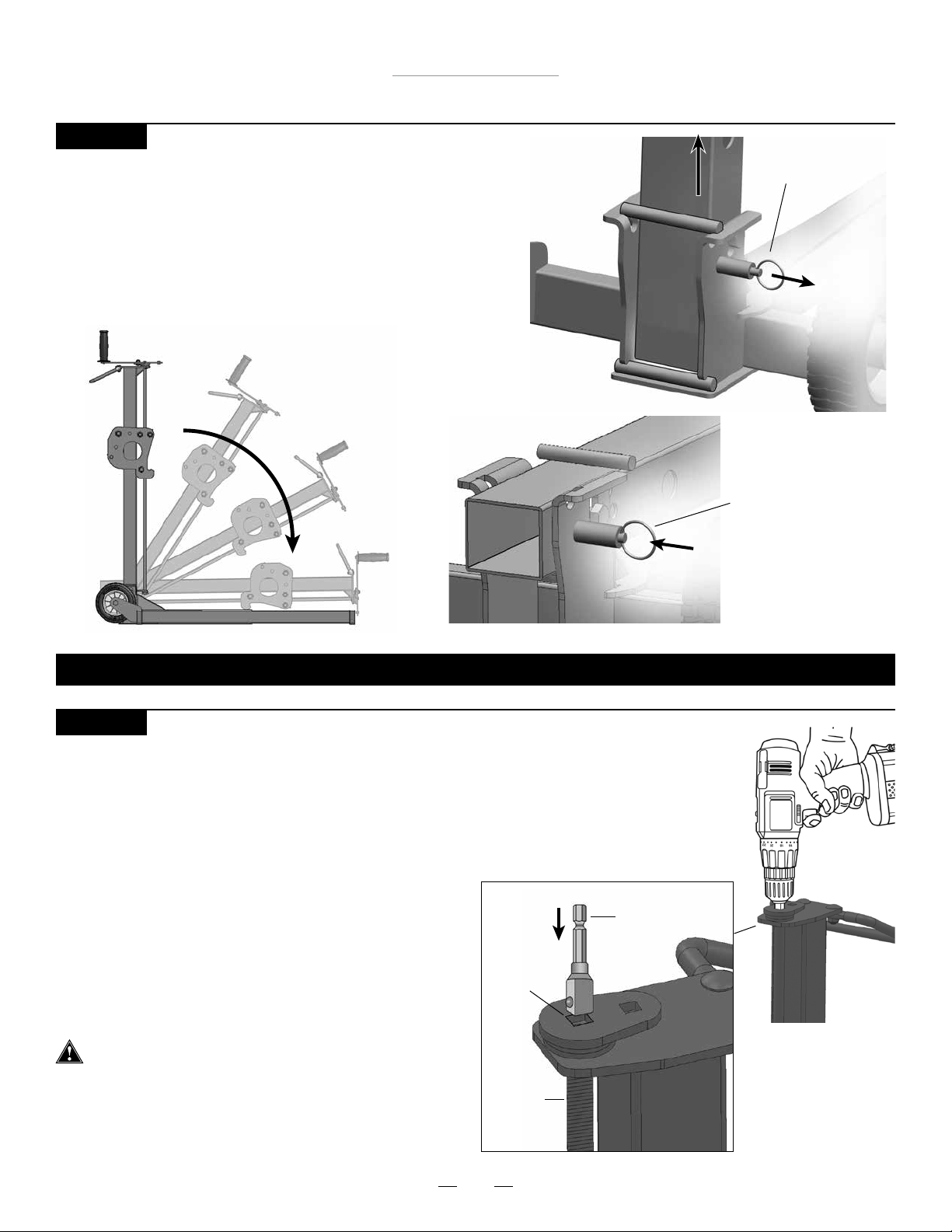
STEP 21
Folding the MoJack 750XT
• Pull locking pin out to unlock.
• Raise the Tower out of the Base by pulling up on the
Grip Handle and then lower the Tower.
• The tower will be securely locked in place when the
locking pin retracts.
Lift Tower
out of Base
Tower Locking Pin
(unlocked position)
Tower Locking
Pin
(locked position)
THE MOJACK 750XT IS NOW READY FOR STORAGE OR TRANSPORT.
STEP 22
Raising the MoJack 750XT with a power drill (optional)
• The MoJack 750XT can be raised or lowered by using a
variable speed corded drill (7 amp minimum) or variable
speed cordless drill (18V minimum).
• The drill will require a 3/8” square driver (not provided).
• Remove Crank Handle by taking out the nut and bolt
which reveals the 3/8” Square Receiver.
• Firmly insert the 3/8” driver in the Square Receiver.
Rotate the drill forward (clockwise) to raise
the Lift Arm and rotate the drill in reverse
(counterclockwise) to lower the Lift Arm.
• Carrier Locking Pin must be pulled out when
lowering until it clears the bottom Safety Hole.
Operator must have a rm grip on the drill before
raising or lowering the Lift Arm.
• Follow all other operating instructions while using the
drill attachment.
• Replace the Crank Handle for future use.
3/8”
Square
Driver
Square
Receiver
Screw
Thread
18
Page 19
MoJack 750XT Lift
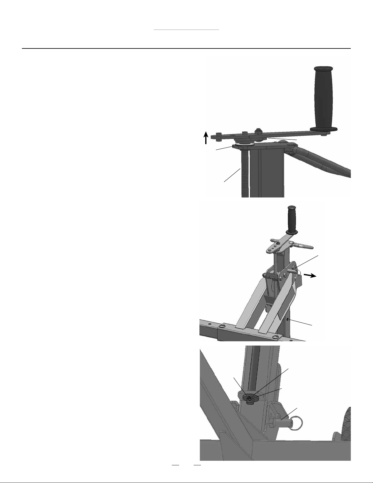
Maintenance Schedule
• Before each use, always check for any worn, loose or
damaged parts on the MoJack 750XT. If any damaged parts
are present, do not use the MoJack 750XT and contact
MoJack at 1-877-575-3173.
• Clean and oil the screw thread after every 50 uses or at
least once a year using light machine oil.
• Place lithium grease between the Crank Handle Base and
the brass bearing after every 50 uses or once a year.
Without weight on carrier, lift the Crank Handle to create
a small gap between the brass bearing and the Crank
Handle Base. Use a small brush to apply the lithium
grease between the two surfaces.
• Place lithium grease on or around Screw Thread Bottom,
Roll Pin and Screw Thread Bottom Washer after every 50
uses or at least once a year.
• Spray grease or lube in Locking Pin holes and shaft after
every 50 uses or at least once a year.
• (Optional) Check for Carrier Locking Pin operation. Turn
top Crank Handle to raise the Lift Arm to the rst Safety
Hole and listen for click as pin pops into hole. After a
click is heard, reverse direction of Crank Handle rotation
without pulling on the Carrier Locking Pin ring. Pin
should hold Carriage at height. Do not force the handle
past the lock point, as this may damage the Screw
Thread. If Carrier Locking Pin does not hold Lift Arm
height, do not use the MoJack 750XT and contact MoJack
at 1-877-575-3173. After checking Carrier Locking Pin
operation, proceed to lower by pulling out on the Carrier
Locking Pin ring.
Crank Handle Base
Brass Bearing
Screw Thread
Carrier
Locking
Pin
Pull Out
to Lower
Safety Hole
19
Roll
Pin
Screw Thread Bottom
Screw Thread
Bottom Washer
Tower Locking Pin
Page 20
MoJack 750XT Lift
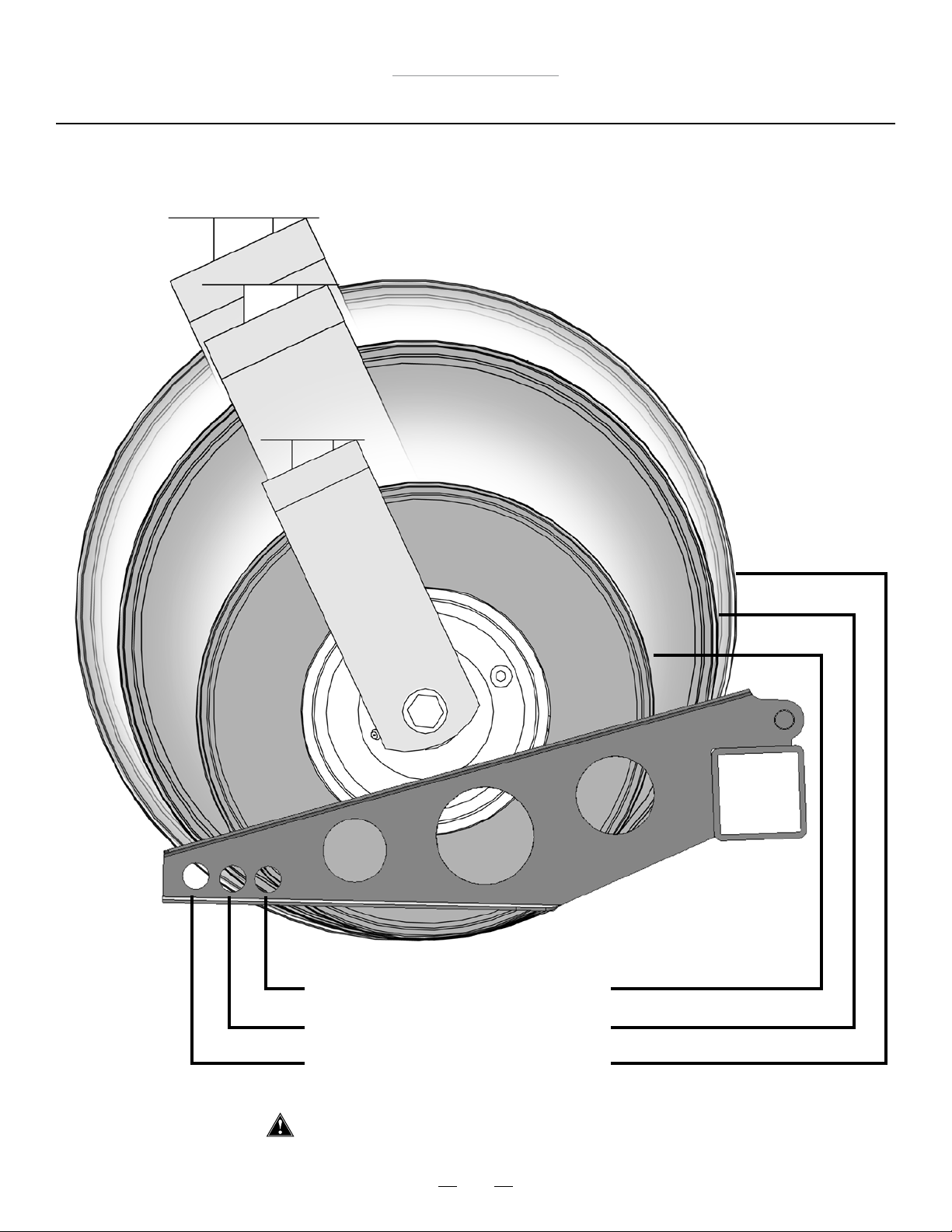
Support Rod Guide for Tire Sizes
10” – 11.5” (25cm – 29cm) Tire Size
12” – 15” (30cm – 38cm) Tire Size
15.5” – 17” (39cm – 44cm) Tire Size
Not for use with tires over 17” (44cm) in size
20
Page 21
Elevador MoJack 750XT
Introducción
Este manual contiene instrucciones sobre montaje, partes, funcionamiento, mantenimiento, ajuste y
seguridad del elevador MoJack 750XT.
ANTES DE UTILIZAR EL ELEVADOR MoJack 750XT,
LEA CON ATENCIÓN TODO EL MANUAL.
Si sigue estas instrucciones de funcionamiento,
mantenimiento y seguridad, prolongará la vida del
elevador MoJack y favorecerá su funcionamiento
seguro.
Todas las partes MoJack han sido rigurosamente
probadas e inspeccionadas en fábrica para garantizar el
cumplimiento de las normas de seguridad pertinentes.
Need
Assistance?
Please DO NOT return this
product to the store.
Our Customer Service
Department is ready to help!
1-877-575-3173
NOTA: Guarde este manual para referencia futura.
NOTA: Emplazamiento de la unidad número de serie.
¿Necesita
ayuda?
¡NO devuelva este producto
a la tienda!
¡Nuestro Departamento de
Servicio de Atención al Cliente
está listo para ayudarle!
1-877-575-3173
Submit your questions online at:
Envie sus preguntas por Internet a:
www.theMoJack.com
Patente #s: U.S., 8,448,920 and 8,387,953
MoJack es una marca registrada de MoJack Distributors, LLC.
MoJack 750XT es una marca registrada de MoJack Distributors, LLC.
© 2014 MoJack Distributors, LLC.
21
Page 22
Elevador MoJack 750XT
Advertencias e instrucciones de seguridad
Asegúrese de leer y comprender todas las instrucciones de seguridad y funcionamiento antes de utilizar el equipo
MoJack 750XT.
No permita que una persona no familiarizada con las instrucciones de seguridad o funcionamiento utilice el equipo MoJack 750XT.
Siga todas las instrucciones de seguridad y servicio proporcionadas por el fabricante de la podadora antes de utilizar el
elevador MoJack 750XT.
No modique de ninguna forma el elevador MoJack. Cualquier modicación anulará todas y cada una de las
garantías existentes y podría poner en riesgo su seguridad personal.
Al utilizar el elevador MoJack 750XT, mantenga a las personas presentes a una distancia segura del equipo.
El elevador MoJack 750XT se debe utilizar sobre una supercie sólida y nivelada.
No levante los e750XTremos delantero y trasero de la podadora al mismo tiempo.
No utilice el equipo MoJack 750XT para elevar objetos que no sean podadoras, salvo que utilice el
accesorio adecuado.
Apague siempre el motor y e750XTraiga la llave antes de comenzar a trabajar en la podadora.
Nunca haga funcionar el motor de la podadora mientras utiliza el elevador MoJack 750XT.
No exceda la capacidad de elevación límite de 750 libras (340 kg).
Si la torre del MoJack EX se inclina al elevar o bajar la podadora, eso indica que existe una sobrecarga. Retire la podadora de inmediato.
Antes de utilizar el elevador MoJack 750XT, la torre debe estar bloqueada en la posición correcta con su pasador de
bloqueo.
El pasador de bloqueo del transportador debe estar bloqueado en la torre antes de comenzar a efectuar cualquier operación de servicio en la podadora.
No quite las advertencias de seguridad ni las calcomanías del equipo MoJack 750XT.
Antes de cada uso, controle si hay partes gastadas, sueltas o dañadas en el elevador MoJack 750XT. Si hubiera partes
dañadas, no utilice el elevador MoJack 750XT y póngase en contacto con MoJack llamando al 1-877-575-3173.
No suba a la podadora mientras la misma se eleva o se baja.
No debe haber nadie en la podadora mientras la misma se eleva o se baja.
Una vez que la podadora se haya elevado a una altura de trabajo, coloque siempre cuñas (no incluidas) detrás de los
neumáticos traseros de la podadora.
Ambos topes de rueda deben estar a la misma distancia del brazo elevador para mantener el equilibrio adecuado.
E750XTraiga todos los accesorios de la podadora antes de utilizar el elevador MoJack 750XT.
Si no cumple con estas advertencias pueden producirse daños a la propiedad, lesiones graves o incluso la muerte.
IMPORTANTE: el elevador MoJack 750XT está diseñado para utilizar solamente con podadoras de montar y tractores
cortacésped de montar. No exceda el peso límite de 750 libras (340 kg). Este equipo nunca debe usarse para efectuar
el servicio de otros tipos de máquinas, salvo que se utilice un accesorio aprobado por MoJack adecuado para el tipo de
máquina. Consulte con el vendedor o distribuidor local de productos MoJack.
22
Page 23

Elevador MoJack 750XT
Garantía y devoluciones
GARANTÍA LIMITADA
MoJack garantiza este producto durante dos años para uso residencial y un año para uso comercial, en caso de producirse defectos de
material o de mano de obra, siempre que el producto se haya utilizado en forma adecuada. MoJack reemplazará las partes defectuosas
sin costo. Esta garantía no cubre productos que hayan sido alterados o ajustados, ni productos que hayan sido utilizados en forma
abusiva o incorrecta. EL RECURSO MENCIONADO CONSTITUYE EL RECURSO ÚNICO Y EXCLUSIVO DEL CLIENTE. MOJACK NO
CONCEDE NINGÚN OTRO TIPO DE GARANTÍA IMPLÍCITA, NI SIQUIERA LA GARANTÍA DE COMERCIABILIDAD E IDONEIDAD PARA UN
FIN PARTICULAR. MOJACK NO SE HARÁ RESPONSABLE POR DAÑOS IMPREVISTOS O DERIVADOS. ALGUNOS ESTADOS O PROVINCIAS NO PERMITEN LA EXCLUSIÓN O LIMITACIÓN DE LAS GARANTÍAS IMPLÍCITAS O DE LOS RECURSOS POR INCUMPLIMIENTO DE GARANTÍAS IMPLÍCITAS; POR LO TANTO, ES POSIBLE QUE ESTAS EXCLUSIONES NO SE APLIQUEN A USTED. ESTA GARANTÍA LIMITADA LE OTORGA DERECHOS LEGALES ESPECÍFICOS Y TAMBIÉN PUEDE TENER OTROS DERECHOS QUE VARÍAN
SEGÚN EL ESTADO O LA PROVINCIA.
¿Qué cubre esta garantía?
Esta garantía proporciona cobertura contra fallos originados por defectos de material o de mano de obra, durante un plazo de dos años a
partir de la compra del equipo para uso residencial y durante un año para uso comercial.
¿Qué NO cubre esta garantía?
Esta garantía no cubre ninguna máquina MoJack que haya sido alterada o ajustada de alguna forma en relación con el modelo original.
No cubrirá ningún producto MoJack que resulte dañado debido a uso incorrecto o excesivo, accidente o negligencia.
Esta garantía no cubre daños imprevistos o derivados.
¿Cuál es el período de cobertura?
Dos años para uso residencial y un año para uso comercial, a partir de la fecha de compra por el propietario original.
¿Qué hará MoJack para resolver los problemas?
Reemplazaremos las partes defectuosas sin cargo (dentro del período de cobertura).
¿Cómo puedo obtener servicio?
Para obtener servicio en el marco de esta garantía, DEBE registrar su producto MoJack dentro de un plazo de treinta (30) días a partir de
la compra. Debe conservar su recibo para demostrar la fecha de la compra. Puede registrar su producto MoJack nuevo en nuestro sitio
Web en www.themojack.com o llamando a nuestro número gratuito 1-877-575-3173.
¿Cómo me pongo en contacto con MoJack por un problema de garantía?
Puede ponerse en contacto con nosotros a través de nuestro sitio Web www.themojack.com o llamando a nuestro número gratuito 1-877575-3173.
¿Tengo otros derechos en virtud de las leyes estatales?
Esta garantía le proporciona derechos legales especícos y también puede tener otros derechos que varían según el Estado.
¿Cuál es la política de devolución?
Consulte la Política de devoluciones y los procedimientos de su lugar de compra para obtener devoluciones y reembolsos.
¿Cómo me pongo en contacto con MoJack?
Puede llamarnos a nuestro número gratuito 1-877-575-3173 o escribirnos a nuestra dirección electrónica [email protected].
23
Page 24
Elevador MoJack 750XT
Parts List
Item
No.
1
2
3
4
5
Qty.
1
1
1
2
2
6
Description
Torre
Brazo elevador
Base
Rueda
Tope de rueda
Item
No.
6
7
8
9
10
Qty.
2
1
1
2
2
Description
Inserto del brazo elevador
Asa de seguridad
Manivela
Varilla de soporte
Correa de seguridad
8
7
2
1
6
10
10
Carrier
5
5
4
4
9
9
3
24
Page 25
Elevador MoJack 750XT
Lista de materiales
Nº
Elem.
11
12
13
14
15
16
17
18
19
Cant. Descripción
1
2
3
3
3
4
1
1
2
Tornillo de cabeza M12 - 1.75 X 80
Tornillo de cabeza M12 - 1.75 X 65
Perno de carruaje M8 - 1.25 X 20
Tuerca Nylock – M12-1.75
Tuerca Nylock – M8-1.25
Pasador de empuje
Pasador de horquilla
Horquilla chica
Horquilla grande
Tornillo de cabeza M12 - 1.75 X 80
11
Tornillo de cabeza M12 - 1.75 X 65
12
Perno de carruaje M8 - 1.25 X 20
13
Pasador de empuje
16
18
Horquilla chica
Herramientas necesarias para el montaje
Tuerca Nylock – M12-1.75
14
15
17
Horquilla grande
19
Tuerca Nylock – M8-1.25
Pasador de horquilla
Llave inglesa de 19 mm (2) Llave inglesa de 13 mm (1)
25
Page 26
Elevador MoJack 750XT
Instrucciones de montaje
PASO 1
E750XTraiga el elevador MoJack 750XT del empaque.
Haga un inventario de las partes para estar seguro de
que posee todas las partes y materiales.
Si faltan partes o materiales, póngase en contacto
con MoJack llamando al 1-877-575-3173 o por correo
electrónico a [email protected].
PASO 2
Monte la rueda a la base , insertando el
tornillo de cabeza y la tuerca Nylock ,
y fíjelos. Repita el procedimiento con la
segunda rueda.
Nota: No apriete demasiado la tuerca Nylock.
PASO 3
Sujete la torre a la base usando el
tornillo de cabeza y la tuerca Nylock como se
indica.
Nota: No apriete demasiado la tuerca Nylock.
4 3
12 14
1 3
11 14
Base
3
Torre
Tuerca Nylock
Tuerca Nylock
1
14
Tornillo de cabeza
14
Rueda
4
Tornillo de
11
cabeza
12
Base
3
26
Page 27
PASO 4
Elevador MoJack 750XT
Instrucciones de montaje
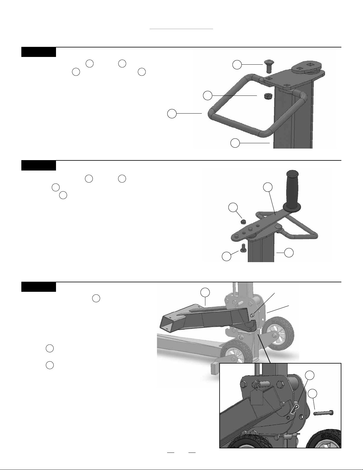
Fije el asa de seguridad a la torre con dos
pernos de carruaje y dos tuercas Nylock .
7 1
13 15
Tuerca Nylock
Asa de seguirdad
7
PASO 5
Fije el asa de seguridad a la torre insertando el perno
de carruaje con la rosca hacia arriba y ajústelo con la
tuerca Nylock .
13
15
18
Nota: Hay dos oricios en la manivela. El oricio más
cercano al asa de goma proporcionará un radio de 6”
(15 cm) para hacer funcionar la manivela. El otro oricio
proporcionará un radio de 8” (20 cm), facilitando la manipulación de la manivela. Utilice el oricio que funcione mejor
con su modelo de podadora.
Perno de carruaje
Perno de carruaje
15
Torre
Tuerca Nylock
13
13
1
Manivela
15
8
Torre
1
PASO 6
Cuelgue el brazo elevador en el transportador,
2
enganchando el área ranurada del brazo elevador
sobre la barra superior del transportador. El brazo
elevador se debe insertar desde la parte delantera
y después bajar para quedar colocado en la
posición correcta. Inserte el pasador de
horquilla a través del oricio del transportador
17
y bloquéelo, colocando la
horquilla en el pasador de horquilla.
18
Brazo elevador
27
2
Barra superior del transportador
Transportador
Horquilla
18
Pasador
17
de
horquilla
Page 28
Elevador MoJack 750XT
Instrucciones de montaje
PASO 7
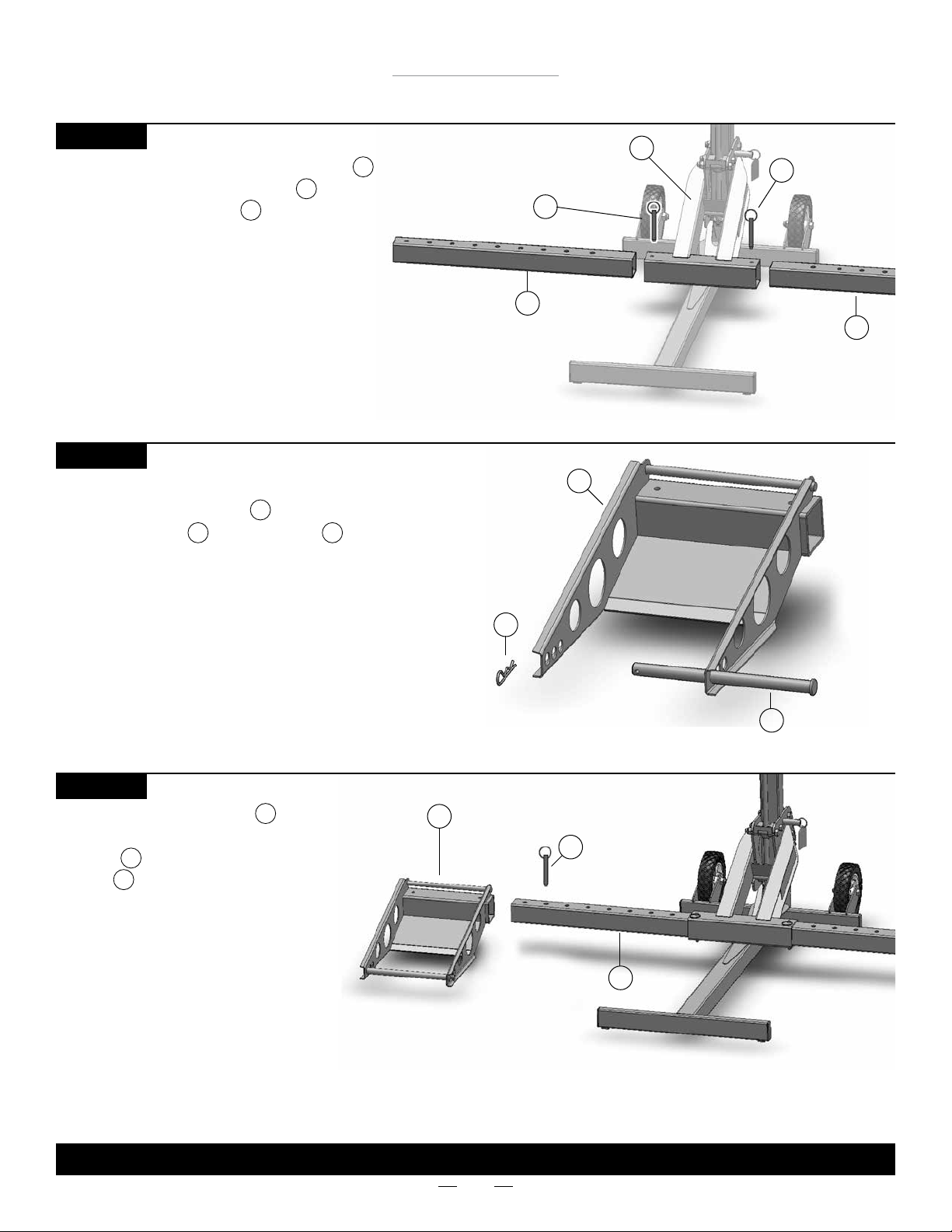
Introduzca los insertos del brazo elevador
a ambos lados del brazo elevador y fíjelos
con pasadores de empuje como se indica.
16
2
6
Inserto del brazo
PASO 8
Prepare los topes de rueda para instalar colocando las
varillas de soporte y las horquillas .
11 19
5
Pasador de
empuje
elevador
Tope de rueda
Brazo elevador
16
6
5
2
Inserto del brazo
Pasador de
16
empuje
elevador
6
PASO 9
Coloque los topes de rueda a
5
ambos lados de los insertos del brazo
elevador y fíjelos con pasadores de
empuje .
6
16
Nota: los topes de rueda se pueden
mover hacia adentro o hacia afuera para
adaptarse a los distintos tamaños de
podadora. Utilice la conguración que
funcione mejor con su modelo de podadora. Las almohadillas de las ruedas
deben estar a la misma distancia del
brazo elevador para mantener el
equilibrio adecuado.
Horquilla
Tope de rueda
5
19
Pasador de
16
empuje
Inserto del brazo
elevador
Varilla de soporte
6
11
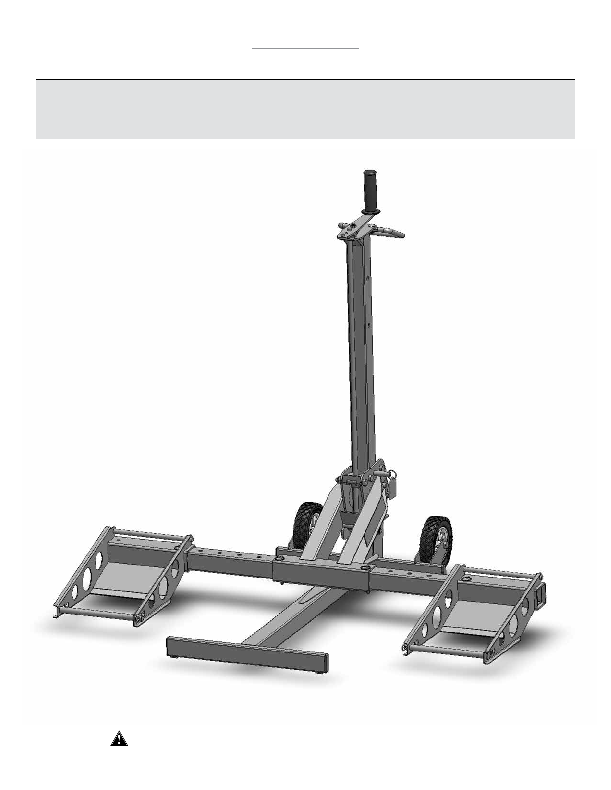
SE HA COMPLETADO EL MONTAJE.
28
Page 29
Elevador MoJack 750XT
Instrucciones de funcionamiento
Algunos pasos de las instrucciones de funcionamiento son iguales a las
instrucciones de montaje. Las instrucciones de funcionamiento mostrarán
un ciclo de trabajo completo del elevador MoJack 750XT.
Ante de utilizar el elevador MoJack 750XT, lea con atención todo el manual.
29
Page 30
Elevador MoJack 750XT
Instrucciones de funcionamiento
Preparación del elevador MoJack 750XT para el uso (pasos 1 - 8)
PASO 1
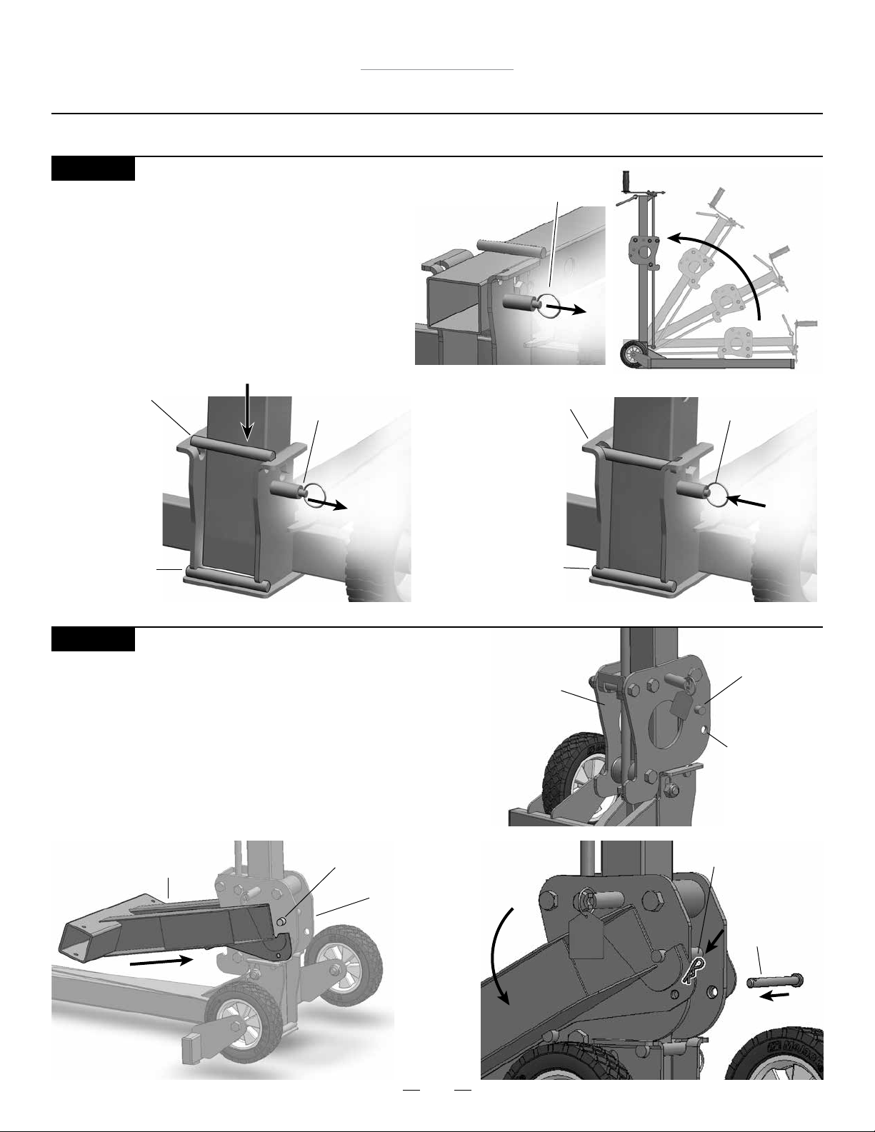
Cómo desplegar el elevador MoJack 750XT
• Tire el pasador de bloqueo a desbloquear.
• Levante la Torre tirando hacia arriba de la manija de
agarre. Una vez que la torre está en la posición
vertical, levante la manija de agarre y colocar la torre
en la Base.
• The tower will be securely locked in place when the
locking pin retracts and the tower is snug in the
channel behind the crossbar.
Caída de la torre en la Base
Travesaño
Cuando la
torre está por
encima de la
barra, la unidad NO está
bloqueado y
no seguro.
Torre Locking Pin
(desbloqueado)
Torre Locking Pin
(desbloqueado)
Travesaño
en el canal
Cuando la torre se
encuentra detrás
de la barra, la uni-
dad se bloquea y
totalmente seguro.
Torre Locking Pin
(bloqueado)
PASO 2
Instalación del brazo elevador
• Cuelgue el brazo elevador en el transportador, enganchando
el área ranurada del brazo elevador sobre la barra superior del
transportador. El brazo elevador se debe insertar desde la parte
delantera y después bajar para quedar colocado en la posición
correcta.
• Fije el brazo elevador al transportador con pasadores de
horquilla y horquilla.
Barra superior del
transportador
Brazo elevador
Transportador
Barra superior del
transportador
Transportador
Pasador de
horquilla agujero
Horquilla chica
Pasador de
horquilla
30
Page 31
Elevador MoJack 750XT
Instrucciones de funcionamiento
PASO 3
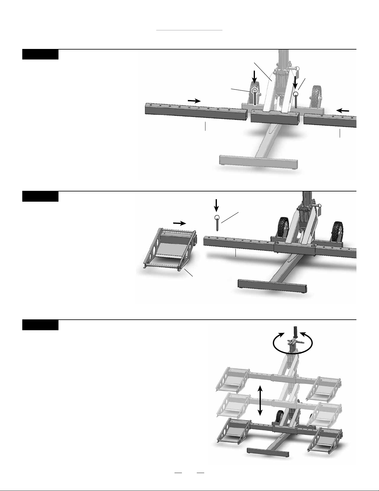
Instalación de los insertos del
brazo elevador
• Introduzca los insertos del brazo
elevador a ambos lados del brazo
y fíjelos con pasadores de empuje.
PASO 4
Instalación de los topes de rueda
• Deslice los topes de rueda en los
insertos del brazo elevador y fíjelos
provisoriamente con pasadores de
empuje.
Brazo elevador
Pasador de
empuje
Pasador de
empuje
Inserto del brazo elevador
Inserto del brazo elevador
Pasador de
empuje
Tope de rueda
PASO 5
Familiarícese con el elevador MoJack 750XT
• Practique cómo subir y bajar el brazo elevador antes de
intentar elevar la podadora (ver pasos 12 a 16, cómo subir y
bajar el brazo elevador).
• Practique el Paso 21 si pretende subir o bajar la podadora
con un accesorio de taladro.
Inserto del brazo elevador
31
Page 32
Elevador MoJack 750XT
Instrucciones de funcionamiento
PASO 6
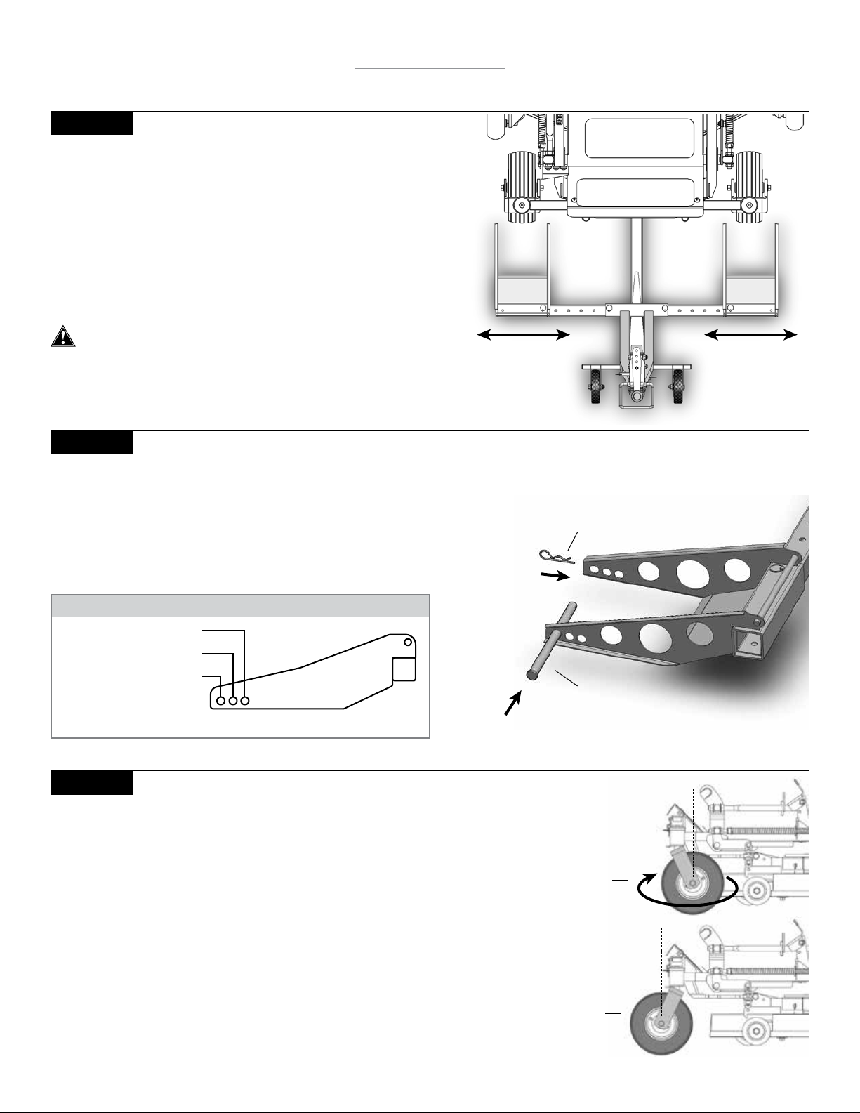
Alineación de los topes de rueda para ajustar a la podadora
• Coloque los neumáticos delanteros de la podadora a una
distancia de 6” (15 cm) frente a los topes de rueda.
• E750XTraiga los pasadores de empuje y alinee los topes de rueda
de forma que los neumáticos delanteros de la podadora queden
centrados en relación con los topes de rueda.
• Reemplace los pasadores de empuje para bloquear los topes de
rueda al brazo elevador.
Ambos topes de rueda deben estar a la misma distancia del
brazo elevador para mantener el equilibrio adecuado.
PASO 7
Ajuste de las varillas de soporte al tamaño de neumático adecuado.
• Ajuste las varillas de soporte sobre los topes de rueda según el tamaño de
los neumáticos delanteros de la podadora. Consulte en el gráco a continuación la ubicación adecuada de la varilla de soporte según el diámetro de
los neumáticos delanteros de la podadora.
• Fije las varillas de soporte a los topes de rueda con horquillas grandes.
GUÍA DE VARILLAS DE SOPORTE PARA TAMAÑOS DE NEUMÁTICO
10” - 11.5” (25 cm - 29 cm)
12” - 15” (30 cm - 38 cm)
15.5” - 17” (39 cm - 44 cm)
Consulte la página 39 para obtener información más detallada.
PASO 8
Posición inversa de los neumáticos delanteros de la podadora
(opcional; si no corresponde, pase al paso 9)
• En algunos casos, la cubierta o las ruedas protectoras de la podadora
tocarán el brazo elevador mientras se eleva la podadora. Esto sucede
con frecuencia si una parte de la cubierta (incluso las ruedas
protectoras) sobresalen de la línea central de las ruedas delanteras
de la podadora.
• Gire las llantas centrales 180º de forma que queden en posición
inversa.
• E750XTraiga las varillas de soporte de los topes de rueda y deslice el
elevador MoJack 750XT debajo de la podadora.
• Fije las varillas de soporte a los topes de rueda con horquillas grandes.
Horquilla grande
Varilla de soporte
Posición
de las
ruedas
hacia
adelante
Posición
inversa
de las
ruedas
32
Page 33
Elevador MoJack 750XT
Instrucciones de funcionamiento
Utilización del elevador MoJack 750XT (Paso 9 - 16)
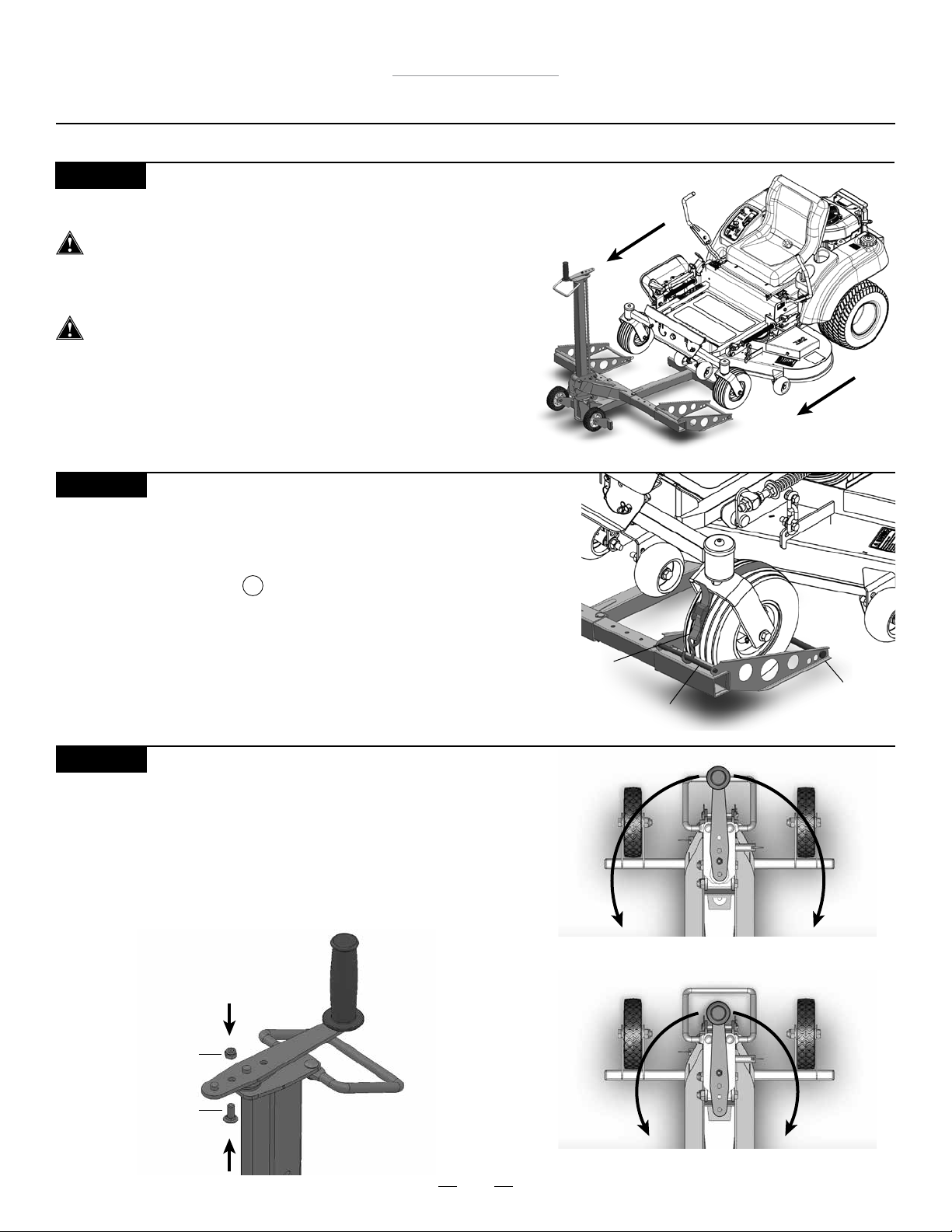
PASO 9
Traslado de la podadora hacia el elevador MoJack 750XT
El elevador MoJack 750XT se debe utilizar sobre una
supercie sólida y nivelada.
• Conduzca o haga rodar la podadora hasta los topes de rueda.
Detenga el motor y e750XTraiga la llave.
PASO 10
Sujeción de las llantas delanteras de la podadora a los topes
de rueda
• Fije las llantas delanteras de la podadora a los topes de rueda utilizando
las correas de seguridad . Asegure el gancho en la correa de la
seguridad a la barra cruzada del cojín de la rueda e inserte la ayuda
Rod en el lazo en la correa de la seguridad separando la ayuda Rod y
después deslizando el lazo de la correa de la seguridad a
través y reatando la ayuda Rod.
• Ajuste las correas de seguridad sobre la parte superior
del neumático para jar la podadora a los topes de rueda.
PASO 11
Ajuste de la manivela (opcional)
• La longitud opcional de la manivela está en la conguración
mayor. Algunas podadoras tienen accesorios protectores o
capós de mayor tamaño que intereren con las manivelas más
grandes. La manivela se puede ajustar e750XTrayendo la tuerca
Nylock y el perno de carruaje y volviéndolos a jar en la
conguración más corta.
10
Correa de
seguridad
Conguración más larga: radio de 8” (20 cm)
Barra transversal
del tope de rueda
Varilla de soporte
Tuerca Nylock
Perno de carruaje
Conguración más corta: radio de 6” (15 cm)
33
Page 34
Elevador MoJack 750XT
Instrucciones de funcionamiento
PASO 12
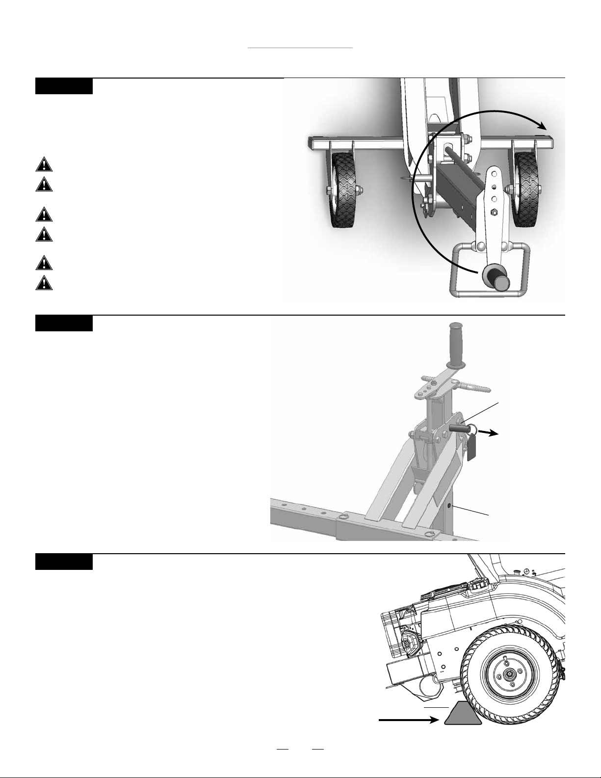
Elevación de la podadora
• Eleve la podadora girando la manivela en sentido horario.
• Consulte el paso 22 para elevar la podadora con un
accesorio de taladro.
No intente levantar más de 750 lbs (340 kg).
El elevador MoJack 750XT se debe utilizar sobre una
supercie sólida y nivelada.
Se debe apagar el motor y e750XTraer la llave.
La podadora debe estar en posición neutral.
Desactive la transmisión si es necesario.
El freno de estacionamiento debe estar desactivado durante este paso.
Las correas de seguridad deben estar jadas con rmeza.
PASO 13
Colocación del brazo elevador en la posición de bloqueo
• Levante el brazo elevador hasta que el pasador de bloqueo del
transportador quede colocado en el oricio de seguridad.
• El pasador de bloqueo del transportador se introduce
automáticamente en los oricios de seguridad cuando el
transportador pasa por los oricios ubicados en la torre al elevarse.
• Nota: Al bajar el brazo elevador, el operador debe tirar
del pasador de bloqueo del transportador
hasta liberar el orificio de seguridad inferior.
PASO 14
Preparación de la podadora para el servicio
• Coloque las cuñas (no incluidas) detrás de los neumáticos posteriores
de la podadora.
• Después active el freno de estacionamiento en la podadora.
• El pasador de bloqueo del transportador debe estar bloqueado en
uno de los dos oricios de seguridad.
Pasador de
bloqueo del
transportador
Tirar
hacia
fuera
para
desbloquear y bajar
Oricio de
seguridad
34
Cuña para rueda
Page 35
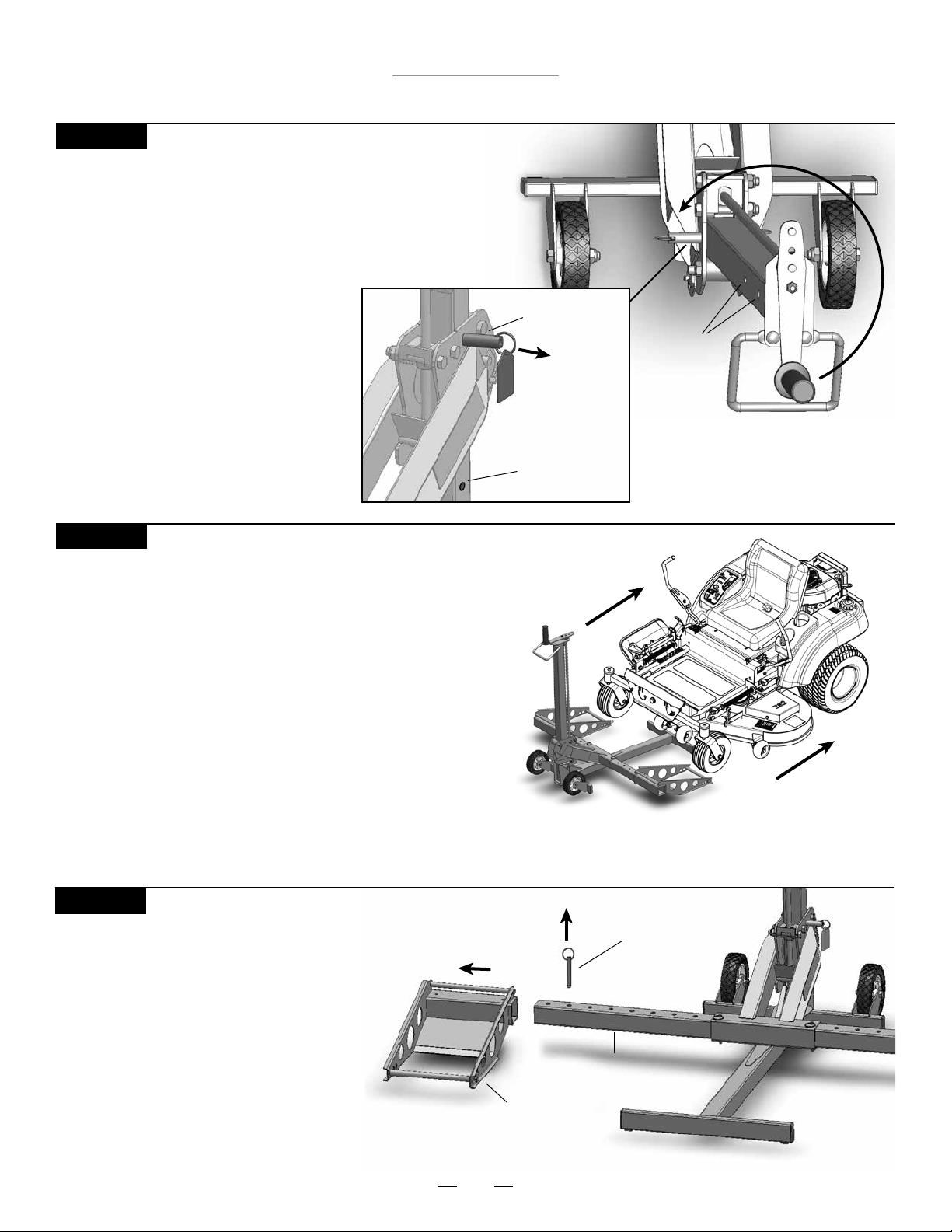
Instrucciones de funcionamiento
PASO 15
Descenso de la podadora
• Quite las cuñas de las ruedas.
• Libere el freno de estacionamiento.
• La podadora debe estar en posición neutral.
Desactive la transmisión si es necesario.
• Tire del pasador de bloqueo del transportador
hacia afuera y manténgalo así, girando
la manivela en sentido antihorario
hasta que los topes de rueda estén
ubicados rmemente en el suelo.
Se debe tirar del pasador de
bloqueo del transportador
hasta que se libere el orificio
de seguridad inferior. No fuerce
la manivela más allá del punto de
bloqueo, de lo contrario puede dañar
la rosca del tornillo.
Elevador MoJack 750XT
Pasador de
bloqueo del
transportador
Oricios de
seguridad
Tirar hacia
fuera para
desbloquear
y bajar
Oricio de
seguridad
PASO 16
Retiro de la podadora del elevador MoJack 750XT
• Quite las correas de seguridad de los neumáticos delanteros
de la podadora.
• La e750XTracción de las varillas de soporte es opcional en
este paso.
• Conduzca o haga rodar la podadora para alejarla de los
topes de rueda.
Preparación del elevador MoJack 750XT para almacenamiento (Paso 17 - 20)
PASO 17
E750XTracción de los topes de rueda
• E750XTraiga los pasadores de empuje de
los topes de rueda y retire los topes de
rueda de los insertos del brazo elevador.
• Guarde los pasadores de empuje dentro
los topes de rueda.
Pasador de empuje
Inserto del brazo elevador
Tope de rueda
35
Page 36
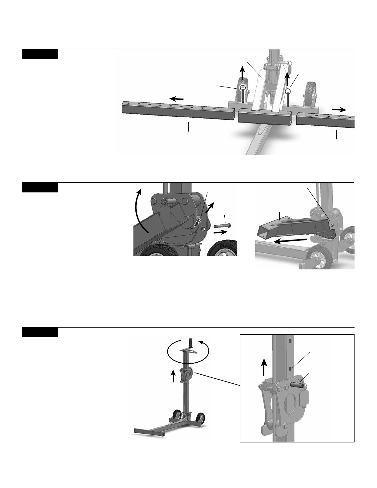
Elevador MoJack 750XT
Instrucciones de funcionamiento
PASO 18
E750XTracción de los insertos del
brazo elevador
• E750XTraiga los pasadores de
empuje del brazo elevador y
e750XTraiga los insertos del
brazo elevador.
• Guarde los pasadores de empuje
en el brazo elevador.
Inserto del brazo elevador
PASO 19
Desenganche del brazo elevador
• E750XTraiga la horquilla pequeña y el
pasador de horquilla del brazo
elevador.
• Desenganche el brazo elevador del
transportador levantando y tirando
de la parte delantera del brazo
elevador.
• Guarde la horquilla y el pasador de horquilla en el brazo elevador.
Pasador de
empuje
Horquilla
Brazo elevador
Pasador de
horquilla
Pasador de
empuje
Inserto del brazo elevador
Barra superior
del transportador
Brazo elevador
PASO 20
Levante el transportador
• Levante el soporte girando el
transportador hacia la derecha
hasta el soporte de bloqueo pin
gotas de en los agujeros de
seguridad
Oricio de
seguridad
Pasador de
bloqueo del
transportador
36
Page 37
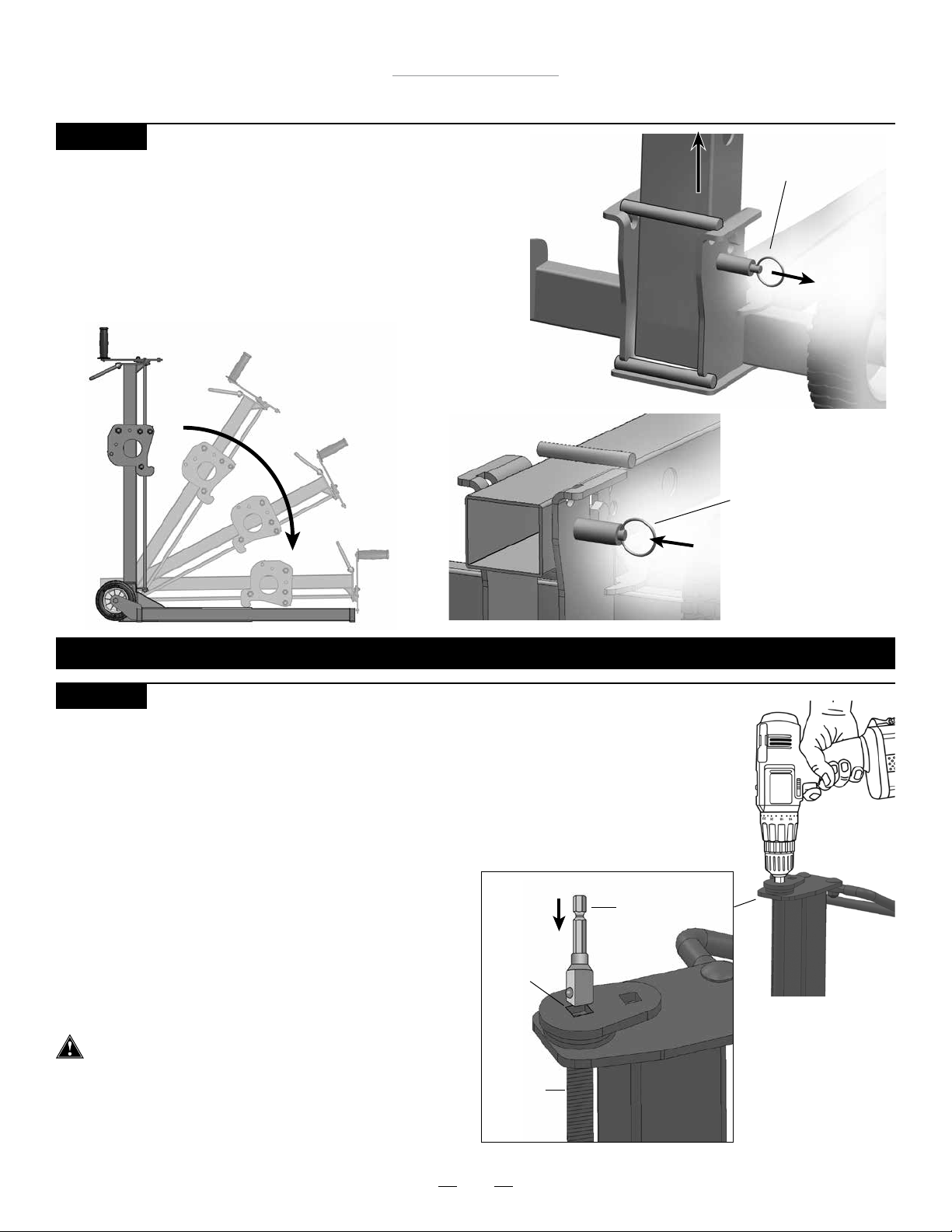
Elevador MoJack 750XT
Instrucciones de funcionamiento
PASO 21
Plegado del elevador MoJack 750XT
• Tire el pasador de bloqueo a desbloquear.
• Levante la Torre de la Base tirando hacia arriba de la
manija de agarre y luego baje la Torre.
• La torre se bloqueará en su lugar cuando se retrae
pasador de bloqueo.
Torre levante
de la base
Torre De Pasador
De Bloqueo (desbloqueado)
Torre De Pasador De
Bloqueo (bloqueado)
EL ELEVADOR MoJack 750XT ESTÁ LISTO PARA SU ALMACENAMIENTO O TRANSPORTE.
PASO 22
Elevación del equipo MoJack 750XT con un taladro eléctrico (opcional)
• El equipo MoJack 750XT se puede elevar o bajar utilizando un taladro con cable de velocidad
variable (7 amp. mínimo) o un taladro sin cable de velocidad variable (18 V mínimo).
• El taladro exigirá un portabrocas de 3/8” (no incluido).
• E750XTraiga la manivela quitando la tuerca y el perno que
ocultan el receptáculo cuadrado de 3/8”.
• Inserte con rmeza el portabrocas de 3/8” en el
receptáculo cuadrado. Haga girar el taladro hacia
delante (sentido horario) para hacer subir el brazo
elevador y en sentido inverso (antihorario) para hacer
descender el brazo elevador.
• Se debe tirar del pasador de bloqueo del
transportador durante el descenso hasta liberar
el orificio de seguridad inferior.
El operador debe sostener el taladro con rmeza
antes de subir o bajar el brazo elevador.
• Siga todas las demás instrucciones de funcionamiento
para utilizar el accesorio de taladro.
• Vuelva a colocar la manivela para el uso posterior.
Receptáculo
cuadrado
Rosca
del
tornillo
Portabrocas
cuadrado de
3/8”
37
Page 38
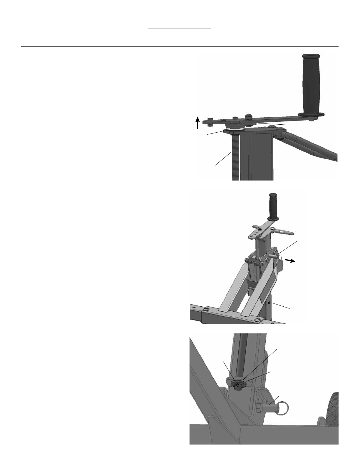
Elevador MoJack 750XT
Programa de mantenimiento
• Antes de cada uso, controle si hay partes gastadas,
sueltas o dañadas en el elevador MoJack 750XT. Si
hubiera partes dañadas, no utilice el elevador MoJack
EZ y póngase en contacto con MoJack llamando
al 1-877-575-3173.
• Limpie y aceite la rosca del tornillo cada 50 usos o como
mínimo una vez al año con aceite lubricante liviano.
• Coloque grasa de litio entre la base de la manivela y el
rodamiento de bronce después de 50 usos o una vez
al año. Sin aplicar peso sobre el transportador, levante la
manivela para crear un pequeño espacio entre el
rodamiento de bronce y la base de la manivela.
Utilice un cepillo pequeño para aplicar la grasa de litio
entre las dos supercies.
Base de la ma-
nivela
Rodamiento
de bronce
Rosca del
tornillo
• Coloque la grasa de litio en o alrededor de la rosca de
tornillo inferior, Roll Pin y tornillo rosca inferior lavadora
después de cada 50 usos o por lo menos una vez al año.
• Grasa spray o lubricante en los oricios de bloqueo pin
y el Oricio de cada 50 usos o por lo menos una vez
al año.
• (Opcional) Controle del funcionamiento del pasador de
bloqueo del transportador. Haga girar la manivela para
hacer subir el brazo elevador al primer oricio de
seguridad y escuche si se produce un clic cuando el
pasador se inserta en el oricio. Después de escuchar el
clic, invierta la dirección de la rotación de la manivela sin
e750XTraer el anillo del pasador de bloqueo del transporta
dor. El pasador debe mantener la altura necesaria. No
fuerce la manivela más allá del punto de bloqueo, de lo
contrario puede dañar la rosca del tornillo. Si el pasador
de bloqueo del transportador no mantiene la altura del
brazo elevador, no utilice el equipo MoJack 750XT y llame a
MoJack al 1-877-575-3173. Después de controlar el
funcionamiento del pasador de bloqueo del transportador,
proceda a bajar e750XTrayendo el anillo del pasador de
bloqueo del transportador.
Pasador de
bloqueo del
transportador
Empujar
hacia
afuera
para bajar
Oricio de
seguridad
Rosca del tornillo fondo
Roll
Pin
Rosca del tornillo
fondo arandela
Pasador de bloqueo
de la torre
38
Page 39
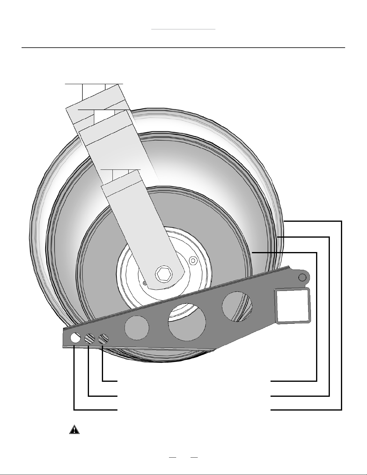
Elevador MoJack 750XT
Guía de varillas de soporte para tamaños de neumáticos
Tamaño de neumático 10” – 11.5” (25 cm – 29 cm)
Tamaño de neumático 12” – 15” (30 cm – 38 cm)
Tamaño de neumático 15.5” – 17” (39 cm – 44 cm)
No es para uso con neumáticos de más de 17” (44cm) de tamaño
39
Page 40

www.theMoJack.com
1-877-575-3173
MoJack and the MoJack logo are registered trademarks of MoJack Distributors, LLC.
© 2014 MoJack Distributors, LLC.
MoJack 750XT is a trademark of MoJack Distributors, LLC. All rights reserved.
Patent pending.
 Loading...