

Moeller DF6-340, DF6-340-75K, DF6-340-11K, DF6-340-15K, DF6-340-90K Hardware And Engineering
...Page 1

Hardware and Engineering
efesotomasyon.com - Klockner Moeller - inverter
DF6-340-...
Frequency Inverters
01/02 AWB8230-1413GB
1st edition, 01/2002
© Moeller GmbH, Bonn
Author: Holger Friedrich, Jörg Randermann
Editor: Michael Kämper
Translator: Dominik Kreuzer
All brand and product names are trademarks or registered
trademarks of the owner concerned.
All rights reserved, including those of the translation.
No part of this manual may be reproduced in any form
(printed, photocopy, microfilm or any otherprocess) or processed,
duplicated or distributed by means of electronic systems without
written permission of Moeller GmbH, Bonn.
Subject to alterations without notice.
Page 2

Warning!
efesotomasyon.com - Klockner Moeller - inverter
Dangerous electrical voltage!
Before commencing the installation
• Disconnect the power supply of the device.
• Ensure that devices cannot be accidentally restarted.
• Verify isolation from the supply.
• Earth and short circuit the device.
• Cover or enclose any adjacent live components.
• Follow the engineering instructions (AWA) for the
device concerned.
• Only suitably qualified personnel in accordance with
EN 50110-1/-2 (VDE 0105 Part 100) may work on this
device/system.
• Before installation and before touching the device ensure
that you are free of electrostatic charge.
• The functional earth (FE) must be connected to the protective
earth (PE) or the potential equalisation. The system installer is
responsible for implementing this connection.
• Connecting cables and signal lines should be installed so
that inductive or capacitive interference does not impair the
automation functions.
• Install automation devices and related operating elements in
such a way that they are well protected against unintentional
operation.
• Suitable safety hardware and software measures should be
implemented for the I/O interface so that an open circuit on the
signal side does not result in undefined states in the
automation devices.
• Ensure a reliable electrical isolation of the extra-low voltage of
the 24 V supply. Only use power supply units complying with
IEC 60364-4-41 (VDE 0100 Part 410) or HD384.4.41 S2.
• Deviations of the mains voltage from the rated value must
not exceed the tolerance limits given in the specifications,
otherwise this may cause malfunction and dangerous
operation.
• Emergency stop devices complying with IEC/EN 60204-1 must
be effective in all operating modes of the automation devices.
Unlatching the emergency-stop devices must not cause a
restart.
• Devices that are designed for mounting in housings or control
cabinets must only be operated and controlled after they have
been installed and with the housing closed. Desktop or
portable units must only be operated and controlled in
enclosed housings.
• Measures should be taken to ensure the proper restart of
programs interrupted after a voltage dip or failure. This should
not cause dangerous operating states even for a short time.
If necessary, emergency-stop devices should be implemented.
• Wherever faults in the automation system may cause injury or
material damage, external measures must be implemented to
ensure a safe operating state in the event of a fault or
malfunction (for example, by means of separate limit switches,
mechanical interlocks etc.).
• Depending on their degree of protection, frequency inverters
may contain live bright metal parts, moving or rotating
components or hot surfaces during and immediately after
operation.
• Removal of the required covers, improper installation or
incorrect operation of motor or frequency inverter may cause
the failure of the device and may lead to serious injury or
damage.
• The applicable national accident prevention and safety
regulations apply to all work carried on live frequency
inverters.
• The electrical installation must be carried out in accordance
with the relevant regulations (e. g. with regard to cable cross
sections, fuses, PE).
• Transport, installation, commissioning and maintenance work
must be carried out only by qualified personnel (IEC 60364,
HD 384 and national occupational safety regulations).
• Installations containing frequency inverters must be provided
with additional monitoring and protective devices in
accordance with the applicable safety regulations.
Modifications to the frequency inverters using the operating
software are permitted.
Moeller GmbH
Safety instructions
I
Page 3

• All covers and doors must be kept closed during operation.
efesotomasyon.com - Klockner Moeller - inverter
• To reduce the hazards for people or equipment, the user must
include in the machine design measures that restrict the
consequences of a malfunction or failure of the drive
(increased motor speed or sudden standstill of motor).
These measures include:
– Other independent devices for monitoring safety-related
variables (speed, travel, end positions etc.).
– Electrical or non-electrical system-wide measures
(electrical or mechanical interlocks).
– Never touch live parts or cable connections of the frequency
inverter after it has been disconnected from the power
supply. Due to the charge in the capacitors, these parts may
still be live after disconnection. Fit appropriate warning
signs.
II
Page 4

01/02 AWB8230-1413GB
efesotomasyon.com - Klockner Moeller - inverter
Contents
About this Manual 5
Abbreviations and symbols 5
1 About the DF6 Frequency Inverter 7
System overview 7
Type code 8
Inspecting the package content 9
Layout of the DF6 10
– Features of the frequency inverters 11
Selection criteria 11
Intended use 12
Service and guarantee 12
2 Engineering 13
Performance features of the DF6 13
Connection to the power supply 15
– Mains configurations 15
– Mains voltage, mains frequency 15
– Interaction with p.f. correction equipment 15
– Fuses and cable cross-sections 15
– Protection of persons and domestic animals
with residual-current protective devices 16
– Mains contactor 16
– Current peaks 16
– Mains choke 17
– Mains filters and radio interference filters 17
EMC requirements 18
– EMC interference class 18
3 Installation 19
Installing the DF6 19
– Mounting position 19
– Installation dimensions 19
– Mounting the DF6 20
EMC compliance 21
– EMC-compliant installation 21
– Using the radio interference filter 21
– EMC measures in the control panel 23
– Earthing 24
– Screening 24
Electrical connection 26
– Connecting the power section 28
–Motor cable 37
– Connecting the control signal terminals 38
1
Page 5

Contents
efesotomasyon.com - Klockner Moeller - inverter
01/02 AWB8230-1413GB
4 Operating the DF6 45
Initial startup 45
Keypad 46
Operation with LCD keypad 46
– Menu overview 47
– Changing display and Basic parameters 48
– Changing the parameters of the extended
parameter groups 48
Display after the supply voltage is applied 49
Connection examples 50
– Operation using an external potentiometer 50
– Operation through an analog setpoint value 50
– Operation with fixed frequencies 51
Operational warnings 52
5 Programming the Control Signal Terminals 53
Overview 53
Analog outputs – AM, AMI and FM 57
– Voltage output (AM) 57
– Current output (AMI) 58
– Frequency output (FM) 58
Analog inputs terminals O, O2 and OI 60
– Frequency setpoint definition 60
– Matching of terminals O, O2 and OI 61
– Analog setpoint value matching 62
Programmable digital inputs 1 to 5 65
– Start/stop 67
– Fixed frequency selection (FF1 to FF4) 68
– Bitwise fixed frequency selection (SF1 to SF7) 70
– Analog input changeover (AT) 72
– Second time ramp (2CH) 73
– Controller inhibit and coasting (free run stop – FRS) 74
– External fault message (EXT) 75
– Unattended start protection (USP) 76
– Reset (RST) 77
– Jog mode (JOG ) 78
– PTC/NTC thermistor input, terminal TH 80
– Software protection (SFT) 81
– Motor potentiometer functions: accelerate (UP) –
decelerate (DWN) – reset frequency (UDC) 82
– Use second parameter set (SET) 84
– Activate DC braking (DB) 85
– Change over current limit (OLR) 87
– Heavy mains starting (CS) 88
– Setpoint value through keypad (OPE) 90
– Three-wire control (STA – STP – F/R) 91
– Activate/deactivate PID control Reset PID and
integral component (PIDC) 92
Programmable relay outputs K11 to K34 93
– Signalling relay terminals K11, K12, K14 93
– Relay outputs K23-K24 and K33-K34 94
– Frequency arrival signal (FA1/FA2/FA3) 94
2
Page 6

01/02 AWB8230-1413GB
efesotomasyon.com - Klockner Moeller - inverter
Contents
– Run signal (RUN) 96
–Overload signal (OL) 97
– PID control deviation signal (OD) 98
– Fault signal (AL) 99
– Instant stop (IP) and undervoltage (UV) 99
– Running time (RNT) and Mains On time (ONT) 100
– Motor thermal overload (THM) 101
6 Setting Parameters 103
Setting the display parameters 104
Basic functions 105
– Input/display frequency value 105
– Acceleration time 1 105
– Deceleration time 1 106
– Direction of rotation 106
Setting the frequency and start signal parameters 107
– Defined frequency setpoint 107
– Start signal 108
– Base frequency 108
– End frequency 108
Voltage/frequency characteristic and voltage boost 109
–Boost 109
– Voltage/frequency characteristics 109
DC braking (DCB) 112
Operating frequency range 114
Acceleration pause 115
PID control 116
– PID control 116
– Structure and parameters of the PID controller 119
– Example for setting K
and T
p
i
125
– Application examples 126
Automatic voltage regulation (AVR) 128
Energy-saving mode 128
Time ramps 129
Acceleration and deceleration characteristics 130
Automatic restart after a fault 132
Electronic motor protection 135
– Tripping characteristics with increased
overload protection 135
– Tripping characteristic with normal overload protection 136
– Tripping characteristic at adjustable overload protection 136
Current limit 138
Parameter protection 139
Controlled deceleration 140
Other functions 142
– Inhibit direction 142
– Starting behaviour 142
–Display mode 143
– Pulse frequency 144
– Initialization 147
– Country version 147
– Frequency factor for display through PNU d007 147
– OFF key disabled 147
– Motor restart after removal of the FRS signal 148
3
Page 7

Contents
efesotomasyon.com - Klockner Moeller - inverter
01/02 AWB8230-1413GB
– Controlling the internal braking transistor
(11 and 15 kW only) 148
– Type of motor stop 149
– Fan control 149
–Debug mode 149
Motor data 149
User-defined parameters – parameter group U 150
7 Messages 151
Fault messages 151
– State of frequency inverter on fault message 151
– Fault message indication 151
– Fault history register 152
Other messages 154
Warnings 155
8 Troubleshooting 157
Appendix 159
Technical Data 159
Weights and dimensions 163
Cables and fuses 164
Mains contactors 165
Mains choke 165
RFI filter 166
Standard form for user defined parameter settings 167
Index 179
4
Page 8
01/02 AWB8230-1413GB
efesotomasyon.com - Klockner Moeller - inverter
About this Manual
This manual describes the DF6 series frequency inverters.
This manual contains information you need to install, configure
and operate the DF6 frequency inverters. The features, parameters
and functions are described in detail, with examples for the most
important applications. All information applies to the specified
hardware and software versions.
Abbreviations and symbols
The following abbreviations and symbols are used in this manual:
EMC Electromagnetic compatibility
ESD
HF
IGBT
PES
PNU
WE
Electrostatic discharge
High frequency
Insulated gate bipolar transistor
Positive Earth connection of the cable screen
Parameter number
Default setting
All measurements are in millimetres unless otherwise stated.
In some of the illustrations, the enclosure of the frequency inverter
and other components affecting equipment safety have been
omitted for improved clarity. However, the frequency inverter must
always be operated with the enclosure and all necessary
components that affect equipment safety correctly fitted.
Read the manual thoroughly before you install and operate the
frequency inverter. We assume that you have a good knowledge
of engineering fundamentals and that you are familiar with the
electrical systems and the applicable principles and are able to
read, interpret and apply the information contained in technical
drawings.
X Indicates instructions to be followed
Indicates useful tips and additional information
h
Caution!
Warns of the possibility of minor material damage.
Warning!
Warns of the possibility of major material damage and
minor injury.
Warning!
Warns of the possibility of major material damage and
serious or fatal injury.
To improve legibility, the title of the current section is given at the
top of each left-hand page and the current subsection at the top
of each right-hand page, except on the title page of each section
and the blank pages at the end of each section.
5
Page 9

01/02 AWB8230-1413GB
efesotomasyon.com - Klockner Moeller - inverter
6
Page 10
01/02 AWB8230-1413GB
efesotomasyon.com - Klockner Moeller - inverter
1 About the DF6 Frequency Inverter
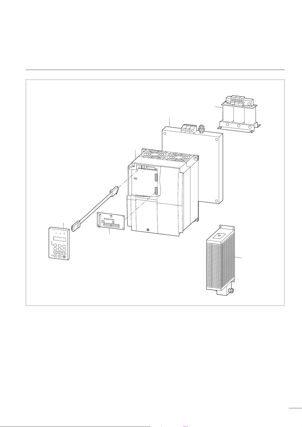
System overview
c
e
d
a
b
Figure 1: System overview
a DEX-DEY-10 external keypad
b Expansion module, for example for PROFIBUS-DP connection: DE6-NET-DP
c DF6 frequency inverter
d DE6-LZ... RFI filter
e Mains choke
f Braking resistor
f
7
Page 11
About the DF6 Frequency
efesotomasyon.com - Klockner Moeller - inverter
Inverter
Type code
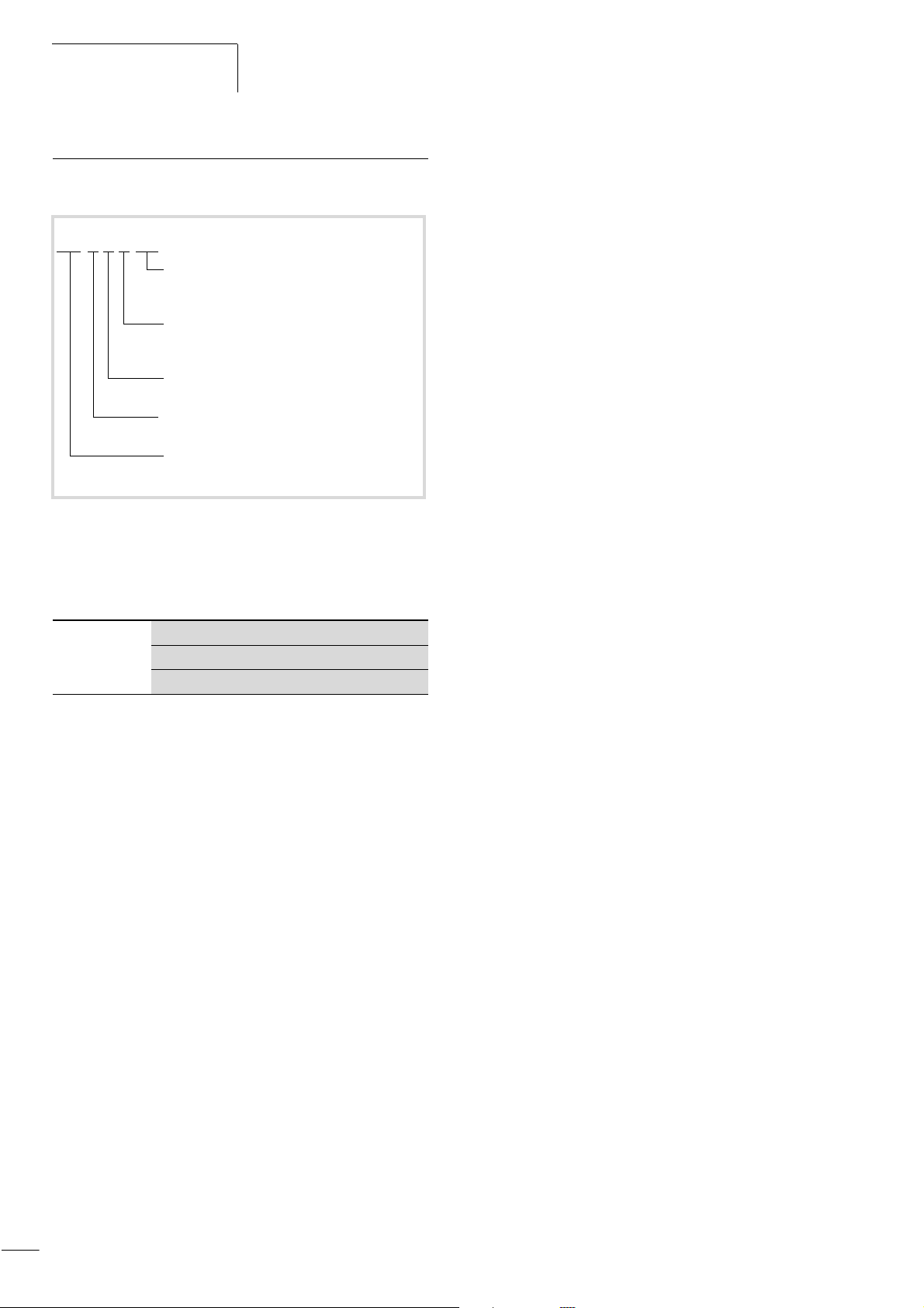
Type codes and type designations of the DF6 frequency inverters:
DF6-xxx-yyy
Motor rating code
Incoming supply: EU rated voltage 400 V
Version and model number
0 = basic version
1 = system devices
2 = voltage code suffix
Supply connection, voltage code (EU rated value)
4 = 400 V (342 V – 0 % to 506 V + 0 %)
Supply connection, phase code
3 = three-phase
Series designation:
Drives Frequency inverter, generation 6
01/02 AWB8230-1413GB
Figure 2: Type codes of the DF6 frequency inverters
Example:
DF6-340-11K
The DF6 frequency inverters
Three-phase mains supply voltage: 400 V
Assigned motor rating: 11 kW at 400 V
8
Page 12
01/02 AWB8230-1413GB
efesotomasyon.com - Klockner Moeller - inverter
Inspecting the package content
Inspecting the package
content
The DF6 frequency inverter has been carefully packaged and
prepared for delivery. The device may be transported only in its
original packaging with a suitable transport system (see weight
details). Observe the instructions and the warnings on the side of
the packaging. This also applies after the device is removed from
the package.
Open the packaging with suitable tools and inspect the contents
immediately on delivery to ensure that they are complete and
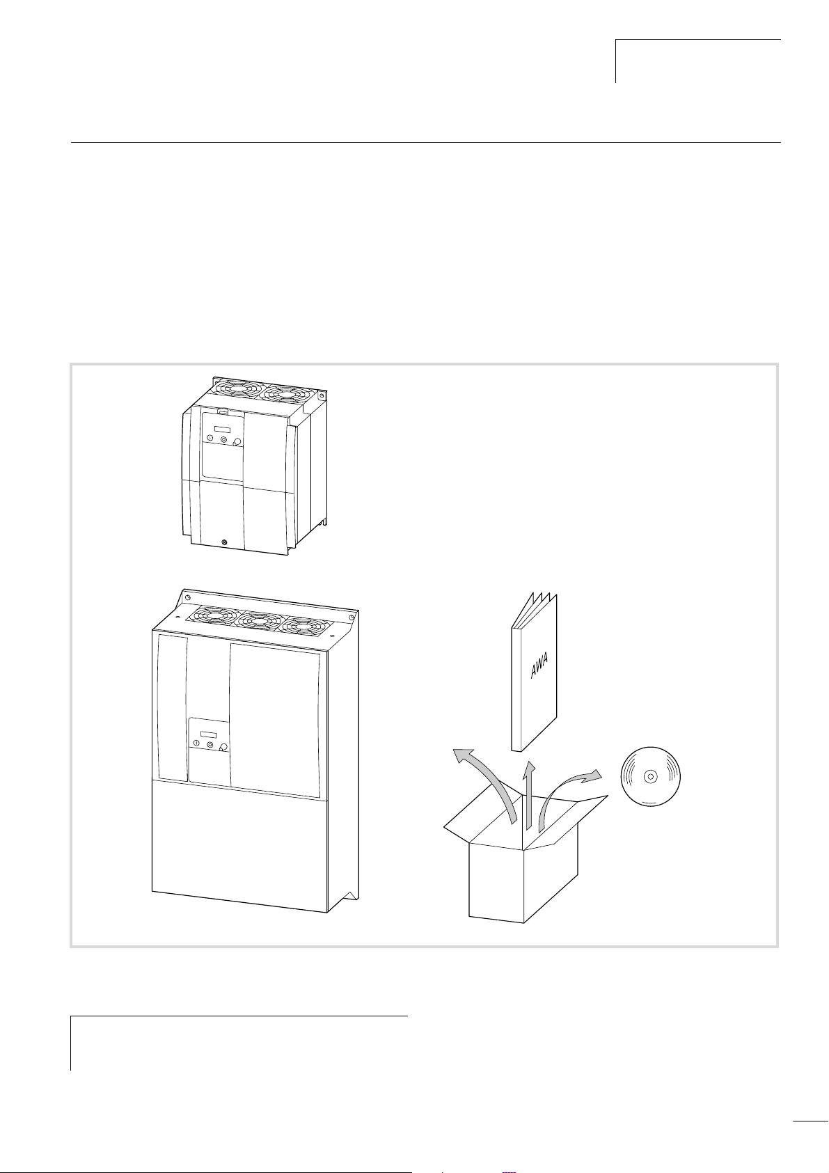
undamaged. The package must contain the following items:
• One DF6 frequency inverter
• Installation instructions, AWA8230-1937
• One CD containing:
– this manual in PDF format and copies in other languages
– the parameterization software
System requirements: PC with Windows 95, 98, 2000, NT
and DEX-CBL-2M0-PC connecting cable
Figure 3: Package content
On the nameplate attached to the frequency inverter,
h
check to ensure that the frequency inverter is the type
which you have ordered.
9
Page 13
About the DF6 Frequency
efesotomasyon.com - Klockner Moeller - inverter
Inverter
Layout of the DF6
01/02 AWB8230-1413GB
b
d
a
l
k
j
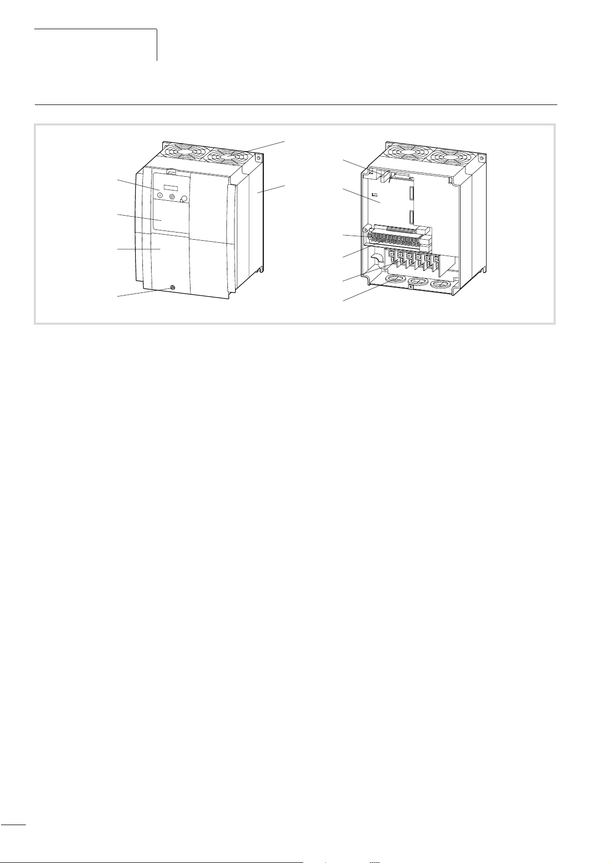
Figure 4: Physical features of the DF6
a Keypad
b Fan
c Heat sink
d Interface connector for keypad
e Two slots for optional modules
f RS 485 interface
c
e
f
g
h
i
g Control signal terminals
h Power terminals
i Cable entry points
j Screw for opening the terminal shroud
k Terminal shroud
l Cover
10
Page 14
01/02 AWB8230-1413GB
efesotomasyon.com - Klockner Moeller - inverter
Selection criteria
Features of the frequency inverters
The DF6 frequency inverters convert the voltage and frequency of
an existing three-phase supply to a DC voltage and use this
voltage to generate a three-phase supply with adjustable voltage
and frequency. This variable three-phase supply allows infinitely
adjustable speed control of three-phase asynchronous motors.
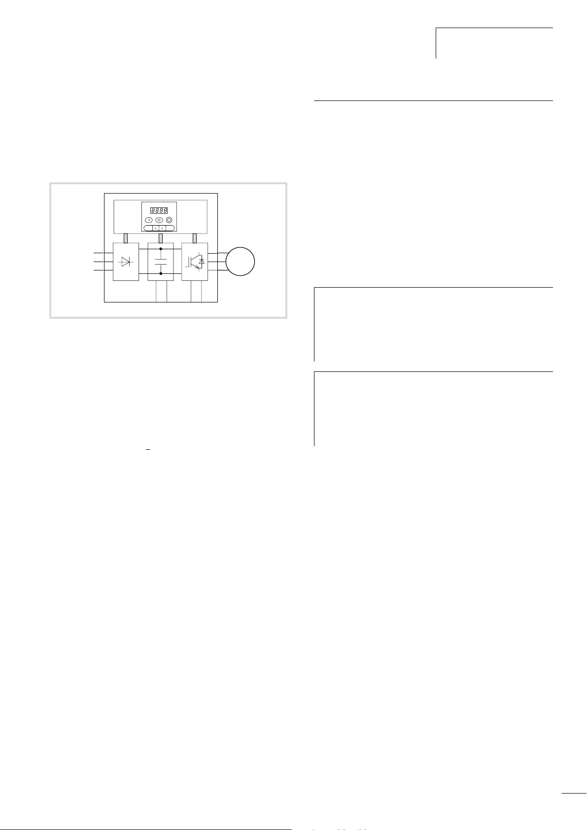
f
h
a
bc d
Figure 5: Function chart of the frequency inverter
a Supply through an interference suppressor
Mains voltage U
3 AC 400 V, 50/60 Hz
b The bridge rectifiers convert the AC voltage of the electrical supply to
a DC voltage.
c The DC link contains a charging resistor, smoothing capacitor and
switched-mode power supply unit. It allows DC link coupling and the
supply of DC current:
DC link voltage (U
d IGBT inverter:
The power inverter converts the DC voltage of the internal DC link to
a variable three-phase alternating voltage with variable frequency.
In conjunction with an external braking resistor, the braking transistor
allows braking of motors with a high moment of inertia or during
extended regenerative operation.
e Output voltage (U
three-phase, variable AC voltage, 0 to 100 % of the input voltage
)
(V
LN
Output frequency (f
Variable frequency, 0 to 400 Hz
Output rated current (I
22 to 253 A at about 1.5 times starting current for 60 s, at a switching
frequency of 5 kHz and at an ambient temperature of 40 °C
Motor connection, assigned shaft output (P
11 to 132 kW at 400 V
f Programmable control section with LCD keypad and interface
(EU-rated voltages):
LN
) = W2 x mains voltage (ULN)
ZK
), motor connection:
2
):
2
):
2N
2
M
3
˜
e
):
Selection criteria
Select the frequency inverter according to the rated current of the
motor. The rated output current of the frequency inverter must
however, be greater than or equal to the rated current of the
motor.
The following drive data is assumed to be known:
• Type of motor (three-phase asynchronous motor)
• Mains voltage = supply voltage of the motor (e.g. 3 ~ 400 V)
• Rated motor current (guide value, dependent on the circuit type
and the supply voltage)
• Load torque (quadratic, constant, with 1.5 times the starting
torque)
• Ambient temperature (maximum temperature 40 °C).
If several motors are connected in parallel to the output of
h
a frequency inverter, the motor currents are subject to
vector addition, i.e. the active in-phase current and
reactive current components are added separately. When
you select a frequency inverter, make sure that it can
supply the total resulting current.
If you connect a motor to an operational frequency
h
inverter, the motor draws a multiple of its rated current.
When you select a frequency inverter, make sure that the
starting current plus the sum of the currents of the
running motors will not exceed the rated output current of
the frequency inverter.
The rated output current of the frequency inverter can be found in
the technical data in the appendix from page 159.
11
Page 15

About the DF6 Frequency
efesotomasyon.com - Klockner Moeller - inverter
Inverter
01/02 AWB8230-1413GB
Intended use
The DF6 frequency inverters are not domestic appliances. They are
designed only for industrial use as system components.
The DF6 frequency inverters are electrical apparatus for controlling
variable speed drives with three-phase motors. They are designed
for installation in machines or for use in combination with other
components within a machine or system.
After installation in a machine, the frequency inverters must not be
taken into operation until the associated machine has been
confirmed to comply with the safety requirements of Machinery
Safety Directive (MSD) 89/392/EEC and meets the requirements of
EN 60204. The owner/operator of the equipment is responsible for
ensuring that the machine is used in compliance with the relevant
EU Directives.
The CE markings on the DF6 frequency inverter confirm that, when
used in a typical drive configuration, the apparatus complies with
the European Low Voltage Directive (LVD) and the EMC Directives
(Directive 73/23/EEC, as amended by 93/68/EEC and Directive 89/
336/EEC, as amended by 93/68/EEC).
In the described system configurations, DF6 frequency inverters
are suitable for use in public and non-public networks. Depending
on their location of use, additional, external filtering may be
necessary.
Service and guarantee
In the unlikely event that you have a problem with your Moeller
frequency inverter, please contact your local sales office.
Please have the following data and information about your
frequency inverter to hand:
• Exact frequency inverter type designation (a nameplate)
• Date of purchase
• Detailed description of the problem which has occurred with the
frequency inverter
If some of the information printed on the nameplate is not legible,
please state only the information which is clearly legible.
Information concerning the guarantee can be found in the Moeller
General Terms and Conditions of Sale.
Connection to IT networks (networks without a ground potential
reference point) is not permitted as the devices internal filter
capacitors connect the network to the ground potential
(enclosure). On earth free networks, this can lead to dangerous
situations or damage the device (isolation monitoring is required).
To the output of the frequency inverter (terminals U, V, W) you
may not:
• connect a voltage or capacitive loads (e.g. phase compensation
capacitor),
• connect multiple frequency inverters in parallel,
• make a direct connection to the input (bypass).
Observe the technical data and terminal requirements. For
additional information, refer to the equipment nameplate or label
and the documentation.
Any other usage constitutes improper use.
12
Page 16

01/02 AWB8230-1413GB
efesotomasyon.com - Klockner Moeller - inverter
2 Engineering
This section describes the “Performance features of the DF6“ and
the requirements and directives concerning the following:
• Connection to the power supply
• EMC requirements
Performance features of the DF6
Ambient temperatures
Operation
Storage Ta = –20 to +65 °C
Transport
Permissible environmental conditions
Resistance to vibration Impact and vibration:
Degree of pollution
Packaging
Climatic conditions
Installation altitude
Mounting position
Free surrounding areas
Electrical data
Emitted interference IEC/EN 61800-3 (EN 55011 group 1, class B)
Noise immunity
Insulation resistance
Leakage current to PE
Degree of protection
Protection against direct contact
Protective isolation against switching
circuitry
Protective measures
Open-/closed-loop control
Modulation method Pulse width modulation (PWM), V/f characteristics control (linear, quadratic)
Switching frequency
Torque
Output frequency
1)
Ta = –10 to +40 °C with rated current Ie without derating,
up to +50 °C with reduced pulse frequency of 2 kHz and output current reduced to 80 % I
Ta = –25 to +70 °C
• DF6-340-11K to DF6-340-30K: Up to 5.9 m/s
• From DF6-340-37K: up to 2.94 m/s
VDE 0110 Part 2, pollution degree 2
Dustproof packaging (DIN 4180)
Class 3K3 according to EN 50178 (non-condensing, average relative humidity 20 to 90 %)
Up to 1000 m above sea level
Vertically suspended
100 mm above and below device
IEC/EN 61800-3, industrial environment
Overvoltage category III according to VDE 0110
Greater than 3.5 mA according to EN 50178
IP20
Finger and back-of-hand proof (VBG 4)
Safe isolation from the mains. Double basic isolation according to EN 50178
Overcurrent, earth fault, overvoltage, undervoltage, overload, over temperature, electronic motor
protection: I
5 kHz (default), can be changed between 0.5 and 12 kHz
At start 1.5 x MN for 60 s at assigned motor rating, every 600 s, 2 x MN for 0.5 s
Range 0.1 to 400 Hz
Frequency resolution
Error limit at 25 °C g10 °C
0.1 Hz, at digital setpoint, maximum frequency/1000 at analog setpoint value
Digital setpoint definition g0.01 % of the maximum frequency
Analog setpoint definition g0.2 % of the maximum frequency
2
2
(0.3 g) at 10 to 55 Hz
2
t monitoring and PTC input (thermistor or temperature contact)
(0.6 g) at 10 to 55 Hz
e
13
Page 17

Engineering
efesotomasyon.com - Klockner Moeller - inverter
Relays
Changeover contacts • Contacts K11-K14
– 250 V AC, 2 A (resistive load)
– 250 V AC, 0.2 A (inductive load, p.f. = 0.4)
– 100 V AC, minimum 10 mA
– 30VDC, 8A (resistive load)
– 30 V DC, 0.6 A (inductive load, p.f. = 0.4)
– 5 V DC, minimum 100 mA
• Contacts K11-K12
– 250 V AC, 1 A (resistive load)
– 250 V AC, 0.2 A (inductive load, p.f. = 0.4)
– 100 V AC, minimum 10 mA
– 30 V DC, 1 A (resistive load)
– 30 V DC, 0.2 A (inductive load, p.f. = 0.4)
– 5 V DC, minimum 100 mA
Make contacts
Internal voltages
Control 24 V DC, maximum 30 mA
Setpoint definition
Analog and digital actuation
Analog inputs • 1 input, 0 to 10 V, input impedance 10 kO
Digital inputs
Analog outputs
Relay outputs
Keypad (built-in)
Operation 6 function keys for controlling and parameterizing the DF6
Display
Potentiometer
1) If the frequency inverter is to be installed in a control panel, enclosure or similar installation, the temperature within the enclosure or control panel is
considered to be ambient temperature T
limits.
• Contacts K23-K24 and K33-K34
– 250 V AC, 5 A (resistive load)
– 250 V AC, 1 A (inductive load, p.f. = 0.4)
– 30 V DC, 5 A (resistive load)
– 30 V DC, 1 A (inductive load, p.f. = 0.4)
– 5 V DC, minimum 1 mA
10 V DC, maximum 10 mA
• 1 input, 4 to 20 mA, load impedance 250 O
• 1 input, +10 to –10 V, input impedance 10 kO
5 inputs, user-configurable and one input for “start/stop clockwise operation”
• 1 output for motor frequency or current, 10 V, up to 1.2 mA
• 1 output, 0 to 10 V, up to 2 mA, user-configurable
• 1 output, 4 to 20 mA, user-configurable
One changeover contact and two make contacts, user-configurable
Four-digit, 7-segment display and ten LEDs (for status signals)
Setpoint definition (0 to 270°)
. The use of fans should be considered to ensure that the ambient temperature remains within permissible
a
01/02 AWB8230-1413GB
14
Page 18

01/02 AWB8230-1413GB
efesotomasyon.com - Klockner Moeller - inverter
Connection to the power supply
Connection to the power
supply
The DF6 frequency inverters can not be used in every network
configuration without limitations (network configuration
according to IEC 364-3).
Mains configurations
Networks with earthed centre point (TT/TN networks):
• DF6 frequency inverters can be used without limitations in TT
and TN networks. The ratings of the DF6 frequency inverters
must, however, be observed.
Networks with isolated centre point (IT networks):
• The use of DF6 frequency inverters in IT networks is only
permissible to a limited extent. In this case, a suitable device
(isolation monitor) to monitor earth faults and isolate the
frequency inverter from the mains must be used.
Caution!
In the event of an earth fault in an IT system, the
capacitors of the frequency inverter which are switched to
earth are subjected to a very high voltage, and safe
operation of the frequency inverter is no longer
guaranteed. To overcome this problem,fit additional
isolating transformer to the frequency inverter’s supply
and earth the transformer’s secondary side at its centre
point to form, in effect, an individual TN network for the
frequency inverter.
Mains voltage, mains frequency
The ratings of the DF6 frequency inverters cover European and
American standard voltages:
• 400 V, 50 Hz (EU) and 460 V, 60 Hz (USA)
The permissible mains voltage range is:
• 380/480 V: 342 V – 0 % to 528 V + 0 %
The permissible frequency range is 47 Hz – 0 % to 63 Hz + 0 %.
Interaction with p.f. correction equipment
The DF6 frequency inverters absorb only a small fundamental
reactive power from the AC supply. A p.f. correction is therefore
not necessary.
Caution!
Operation of DF6 series frequency inverters on the mains
with p.f. correction equipment is only permitted when this
equipment is dampened with chokes.
Fuses and cable cross-sections
The fuse ratings and cable cross-sections required for the network
connection depend on the rating of the frequency inverter and the
drive’s operating mode.
Caution!
When selecting the cable cross-section, take the voltage
drop under load conditions into account. Compliance to
further standards (e.g. VDE 0113, VDE 0289) is the
responsibility of the user.
The recommended fuses and their assignment to the DF6
frequency inverters are listed in the appendix, section “Cables and
fuses”, page 164.
The national and regional standards (e.g. VDE 0113, EN 60204)
must be observed and any required approvals (e.g. UL) at the site
of installation must be fulfilled.
When the device is operated in a UL approved system, only
ULapproved fuses, fuse bases and cables must be used.
The leakage currents to earth (to EN 50178) are greater than
3.5 mA. The connection terminals marked PE and the enclosure
must be connected to the earth circuit.
Caution!
Observe the specified minimum cross-sections for PE
conductors (EN 50178, VDE 0160) must be observed. Use
a PE conductor whose cross-section is as least as large as
the terminal capacity of the power terminals.
The motor rating to mains voltage assignments are listed in the
appendix, section “Technical Data”, page 159.
15
Page 19
Engineering
efesotomasyon.com - Klockner Moeller - inverter
01/02 AWB8230-1413GB
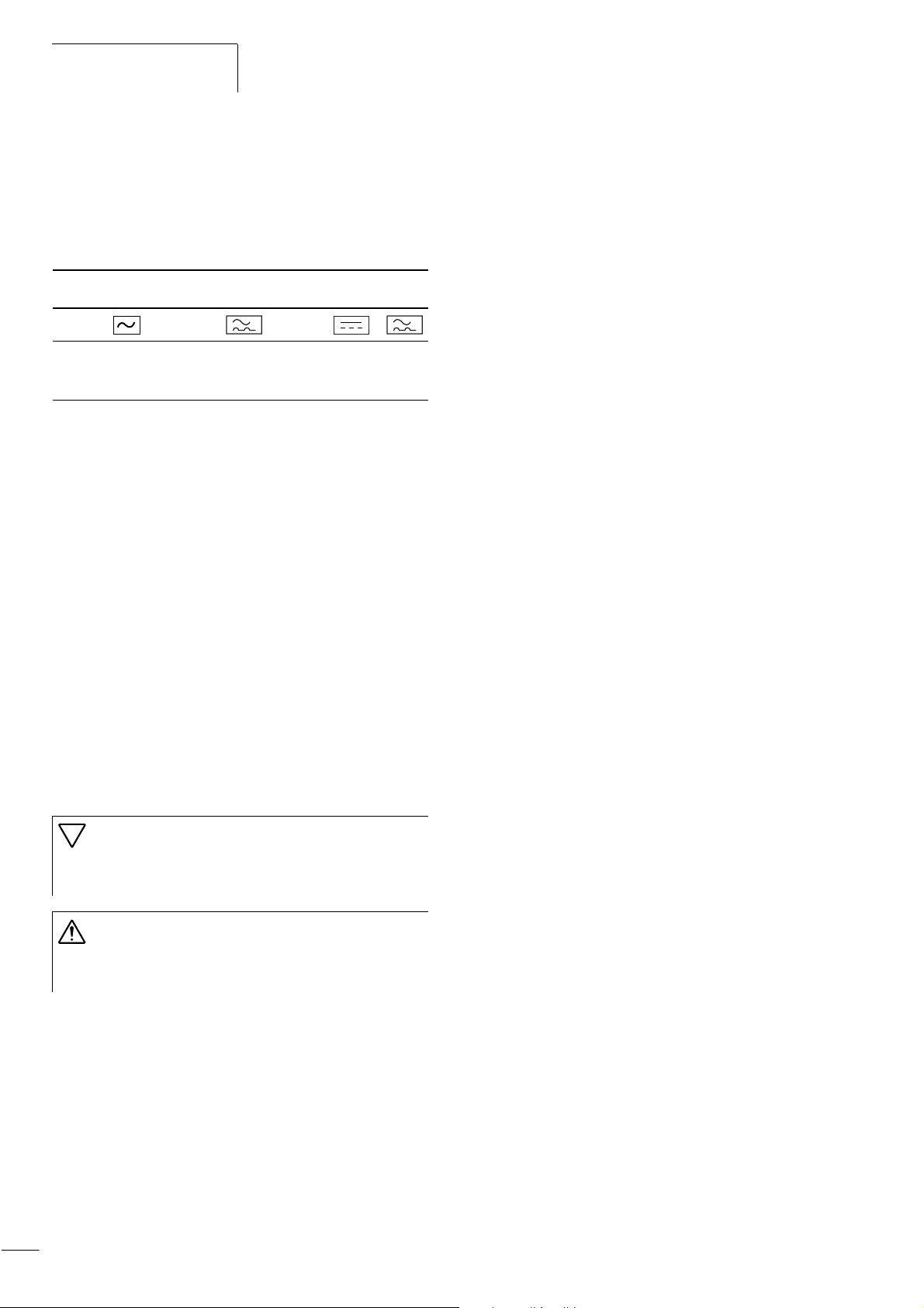
Protection of persons and domestic animals with residualcurrent protective devices
Residual-current circuit breakers (RCCBs; also called earth-leakage
circuit breakers or ELCBs). Universal current sensitive RCCBs
according to EN 50178 and IEC 755.
Identification on the residual-current circuit-breakers
Logo
Model Alternating
current sensitive
(RCCB, Type AC)
Pulse current
sensitive
(RCCB, Type A)
Universal current
sensitive
(RCCB, Type B)
The frequency inverter has a built-in mains rectifier. When a frame
fault occurs, a DC fault current can block the trip of the alternating
current sensitive or pulse current sensitive residual-current circuit
breaker, thereby preventing its protective function. We therefore
recommend the use of:
• all-current sensitive RCCBs with a rated fault current
f 300 mA.
The approximate fault current values of the DF6 frequency
inverters and their assigned radio interference filters are listed in
the appendix, section “RFI filter”, page 166.
Spurious tripping of a residual-current circuit breaker can be
caused by the following:
• capacitive compensation currents in the cable screens,
particularly with long, screened motor cables,
• simultaneous connection of multiple frequency inverters to the
mains supply,
• the use of additional chokes and filters
(radio interference filters, line filters).
Mains contactor
The mains contactor is connected to the mains side input cables
L1, L2, L3 and allows the DF6 frequency inverter on the supplying
network to be switched on and off during operation and to be
disconnected in the event of a fault.
Mains contactors and their assignment to the DF6 frequency
inverters are listed in the appendix, section “Mains contactors”,
page 165.
Current peaks
In the following cases, a relatively high peak current can occur on
the primary side of the frequency inverter (i.e. on the supply
voltage side), which, under certain conditions, can destroy the
input rectifier of the frequency inverter:
• Imbalance of the voltage supply greater than 3 %.
• The maximum power output of the point of supply must be at
least 10 times greater than the maximum frequency inverter
rating.
• If sudden voltage dips in the supply voltage are to be expected,
for example when:
– a number of frequency inverters are operated on a common
supply voltage
– a thyristor system and a frequency inverter are operated on a
common supply voltage
– power factor correction devices are switched on or off
In these cases, a mains choke with about 3 % voltage drop at
rated operation should be installed.
16
Caution!
Residual-current circuit breakers must be installed only on
the primary side between the incoming supply and the
frequency inverter.
Warning!
To prevent the risk of fire, use only cables, residualcurrent circuit breakers and contactors with a suitable
rating.
Page 20

01/02 AWB8230-1413GB
efesotomasyon.com - Klockner Moeller - inverter
Mains choke
The mains choke (also called commutating choke or line reactor)
is connected to the mains side input cables L1, L2, L3. It reduces
the harmonics and therefore reduces the apparent mains current
by up to 30 %.
A mains choke also limits any current peaks caused by potential
dips (e.g. caused by p.f. correction equipment or earth faults) or
switching operations on the mains.
The mains choke increases the lifespan of the internal DC link
capacitors and therefore the lifespan of the frequency inverter. Its
use is also recommended:
• with derating (temperatures above +40 °C, sites of installation
more than 1000 m above sea level),
• with parallel operation of multiple frequency inverters on a
single mains supply point,
• with DC link coupling of multiple frequency inverters
(interconnected operation).
Connection to the power
supply
Mains chokes and their assignment to the DF6 frequency inverters
are listed in the appendix, section “Mains choke”, page 165.
Mains filters and radio interference filters
Mains filters are a combination of mains chokes and radio
interference filters in a single enclosure. They reduce the current
harmonics and dampen high frequency radio interference levels.
Radio interference filters only dampen high frequency radio
interference levels.
Caution!
The mains phase failure detection (PNU b006) does not
operate correctly when a radio interference filter is
installed.
Caution!
When line filters or radio interference filters are used, the
leakage current to earth of the drive unit increases.
Observe this point when installing residual-current
circuit breakers.
17
Page 21

Engineering
efesotomasyon.com - Klockner Moeller - inverter
EMC requirements
01/02 AWB8230-1413GB
The limit values for emitted interference and immunity for variable
speed drives are described in the IEC/EN 61800
-3 Product
Standard.
If you use DF6 frequency inverters in European Union (EU)
countries, you must observe the EMC Directive 89/336/EEC.
The following conditions must be observed to comply with this
Directive:
Supply voltage (mains voltage) for the frequency inverter:
• Voltage fluctuation g10 % or less
• Voltage imbalance g3% or less
• Frequency variation g4 % or less
If one of the conditions listed here cannot be fulfilled, you must
install an appropriate mains choke (a section “Mains choke”,
page 165).
EMC interference class
Installed according to the “EMC guidelines“ in section
“Installation” on page 21 and with the use of a radio interference
filter, the DF6 frequency inverters conform to the following
standards:
• Emitted interference:
IEC/EN 61800-3 (EN 55011 group 1, class B)
• Noise immunity:
IEC/EN 61800-3, industrial environment
With frequency inverters, performance related and emitted
interference increases with the pulse frequency. The frequency at
which performance-related interference occurs also increases with
longer motor cables. When the assigned radio interference filter is
used, the EN 618003 standard is complied to as follows:
Noise immunity
Used with the assigned radio interference filters, the DF6
frequency inverters meet the interference immunity requirements
of the EMC Product Standard IEC/EN 61800
-3 for industrial
environments (second environment) and for domestic use
(first environment).
A “domestic environment” is defined here as a connection point
(transformer feeder) to which domestic households are also
connected.
For industrial systems, the EMC Directive requires electromagnetic
compatibility with the environment as a whole. The Product
Standard regards a typical drive system as a complete unit, i.e. the
combination of frequency inverter, cables and motor.
Emitted interference and radio interference suppression
Used with the assigned radio interference filters, the DF6
frequency inverters meet the requirements of the EMC Product
Standard IEC/EN 61800
-3 for domestic use (first environment) and
therefore also for the higher limit values of industrial environments
(second environment).
To ensure compliance to the limit values, observe the following
points:
• Reduction of performance related interference with line filters
and/or radio interference filters including mains chokes
• Reduction of the electromagnetic emission interference by
screening motor cables and signal cables
• Compliance with installation requirements
(EMC-compliant installation).
Availability
General Limited
First environment
(public mains
network)
Second
environment
(industrial)
1) This is a product with limited availability as defined by IEC/
EN 618003. This product can cause radio-frequency interference in
domestic environments. In this case appropriate protection
measures must be implemented by the user.
18
Up to 10 m motor cable
length at 12 kHz
(maximum pulse
frequency)
Up to 20 m motor cable
lengths at a pulse
frequency of up to 5 kHz
Up to 50 m Up to 50 m
Up to 50 m
1)
Page 22
01/02 AWB8230-1413GB
efesotomasyon.com - Klockner Moeller - inverter
3 Installation
The DF6 frequency inverters should be installed in a control panel
or in a metal enclosure (e.g. IP54).
Installing the DF6
During installation or assembly operations on the
h
frequency inverter, all ventilation slots and openings
should be covered to ensure that no foreign bodies can
enter the device.
The DF6 frequency inverters must be mounted vertically on a nonflammable background.
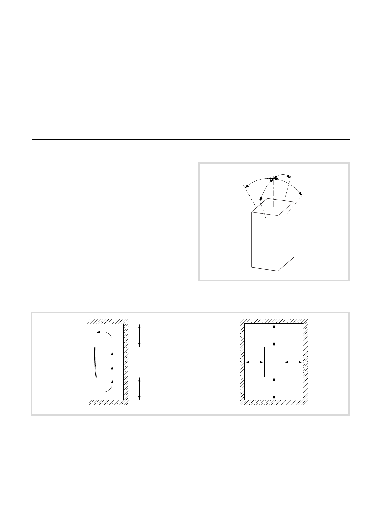
Mounting position
F 30˚
F 30˚
Figure 6: Mounting position
F 30˚
F 30˚
f 100f 100
Figure 7: Installation dimensions
Weights and dimensions of the DF6 are listed in the appendix in
section “Weights and dimensions”, page 163.
f 50
f 100f 100
f 50
19
Page 23
Installation
efesotomasyon.com - Klockner Moeller - inverter
Mounting the DF6
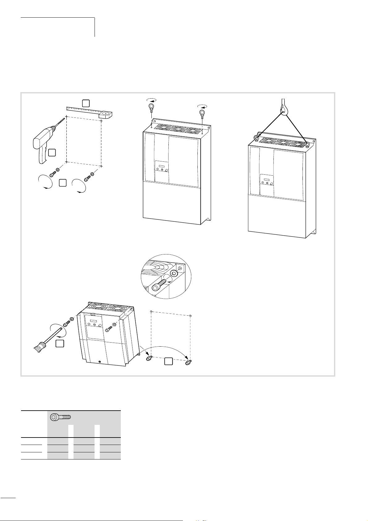
Mount the DF6 frequency inverter as shown in fig. 8 and tighten
the screws to the following torque values (a table 1):
1
2
3
01/02 AWB8230-1413GB
2
Figure 8: Mounting the DF6
Table 1: Tightening torques of the fixing screws
o
[mm]
Nm ft lbs
6 M5 4 3.0
7
10
20
M6 4.9 3.6
M8 8.8 6.5
1
Page 24
01/02 AWB8230-1413GB
efesotomasyon.com - Klockner Moeller - inverter
The fixing screw sizes are listed in the table below:
Table 2: Fixing screw sizes
DF6-340-... a b
Uh
EMC compliance
Z1
G1
6
11K
15K
18K5
22K
30K
37K
45K
55K
75K
90K
110K
132K
189 246
229 376
265 510
300 520
300 670
380 710
EMC compliance
EMC-compliant installation
The frequency inverters operate with fast electronic switching
devices e.g. transistors (IGBT). For this reason, radio interference
can occur on the frequency inverter’s output, which may effect
other electronic devices in the direct vicinity, such as radio
receivers or measurement instruments. To protect against this
radio frequency interference (RFI), the devices should be screened
and installed as far away as possible from the frequency inverters.
3h
a
M
E
E
Figure 9: DF6 and radio interference filters in an insulated metal
enclosure
Z1: RFI filter
G1:Frequency inverter
a Screened motor cable
X Earth the metallic enclosure using a cable which is as short as
possible (a fig. 9).
Using the radio interference filter
The RFI filter should be installed immediately adjacent to the
frequency inverter. The connection cable between the frequency
inverter and filter should be as short as possible. If cables are
longer than 30 cm, use screened cables.
The mounting surfaces for the frequency inverter and radio
interference filter should be as free as possible from paint and oil
residue.
For an EMC-compliant installation, we recommend the following
measures:
• Installation of the frequency inverter in a metallic, electrically
conducting enclosure with a good connection to earth.
• Installation of a radio interference filter on the input of and
immediately adjacent to the frequency inverter.
• Use of screened motor cables (short cable lengths).
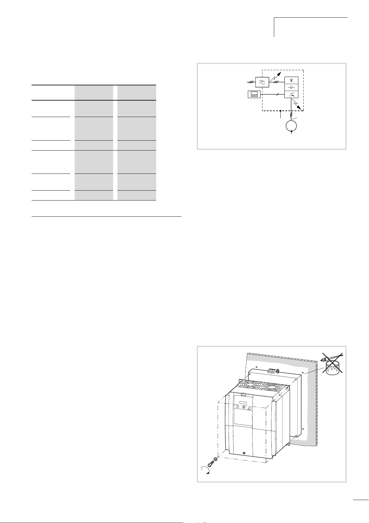
Up to size DF6-340-30K frequency inverters, the assigned
DE6-LZ... radio interference filters (a section “RFI filter”,
page 166) are mounted underneath the inverter (footprint
mounting).
Figure 10: Footprint mounting
21
Page 25
Installation
efesotomasyon.com - Klockner Moeller - inverter
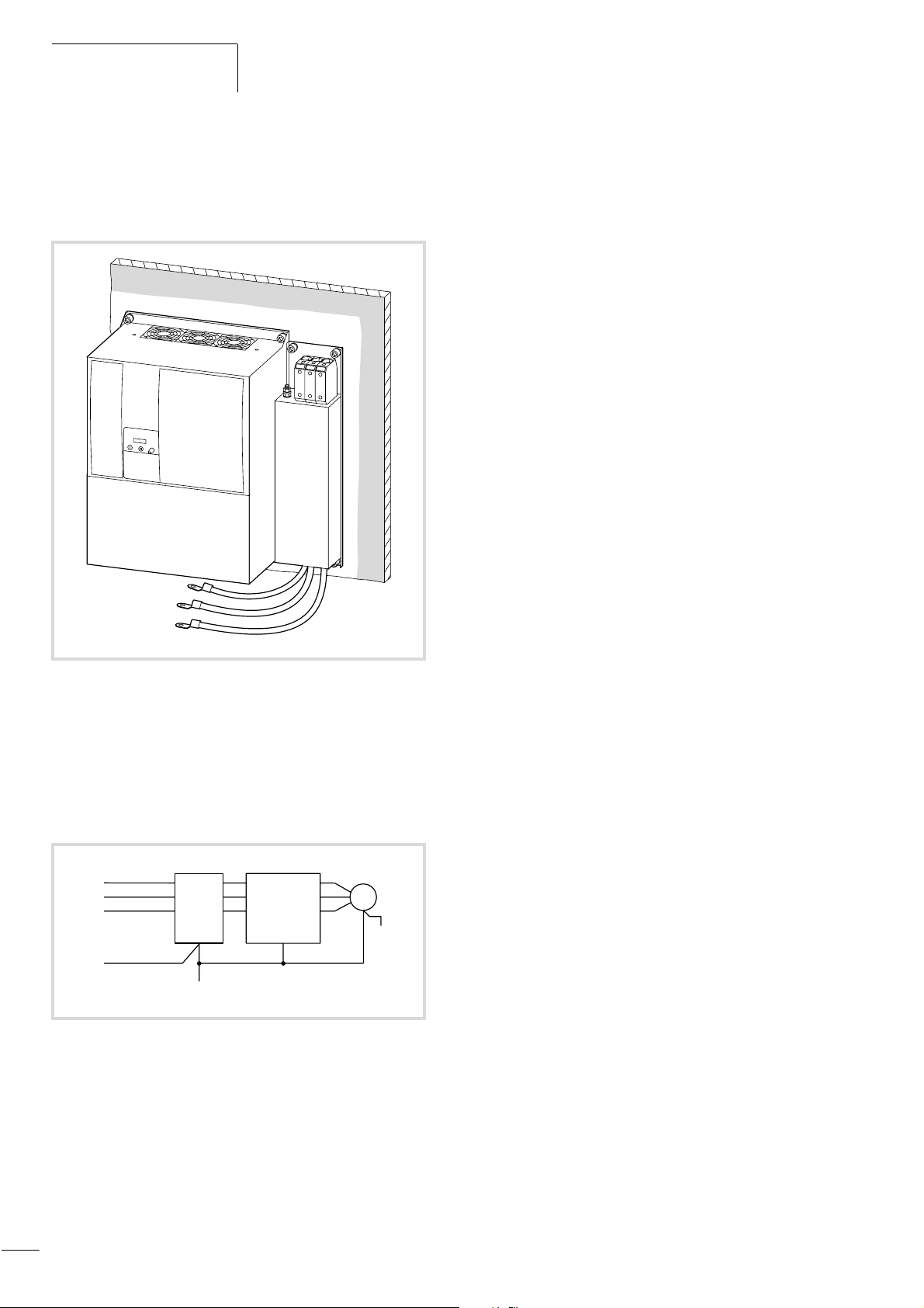
With the DF6-340-37K to DF6-340-132K frequency inverters, fit
the radio interference filters on the side next to the device (booktype mounting). You can fit the RFI filter either to the left or the
right of the frequency inverter.
01/02 AWB8230-1413GB
Figure 11: Book-type mounting (on right side in the example)
Radio interference filters produce leakage currents which, in the
event of a fault (phase failure, load unbalance), can be larger than
the rated values. To prevent dangerous voltages, the filters must
therefore be earthed before use. As the leakage currents are highfrequency interference sources, the earthing connections and
cables must have a low resistance and large contact surfaces.
L1
L2
L3
PE
Z1 G1
R2
L1
S2
L2
T2
L3
L1
L2
L3
e
U
V
W
3h
M
E
E
Figure 12: Earthing measures
Z1: RFI filter
G1:Frequency inverter
22
Page 26
01/02 AWB8230-1413GB
efesotomasyon.com - Klockner Moeller - inverter
EMC compliance
At leakage currents f 3.5 mA, VDE 0160 and EN 60335, one of
the following conditions must be fulfilled:
• the protective conductor has a cross-section f 10 mm
2
,
• the protective conductor is monitored to ensure continuity, or
• an additional protective conductor is installed.
For DF6 frequency inverters, use the assigned DE6-LZ... filters.
EMC measures in the control panel
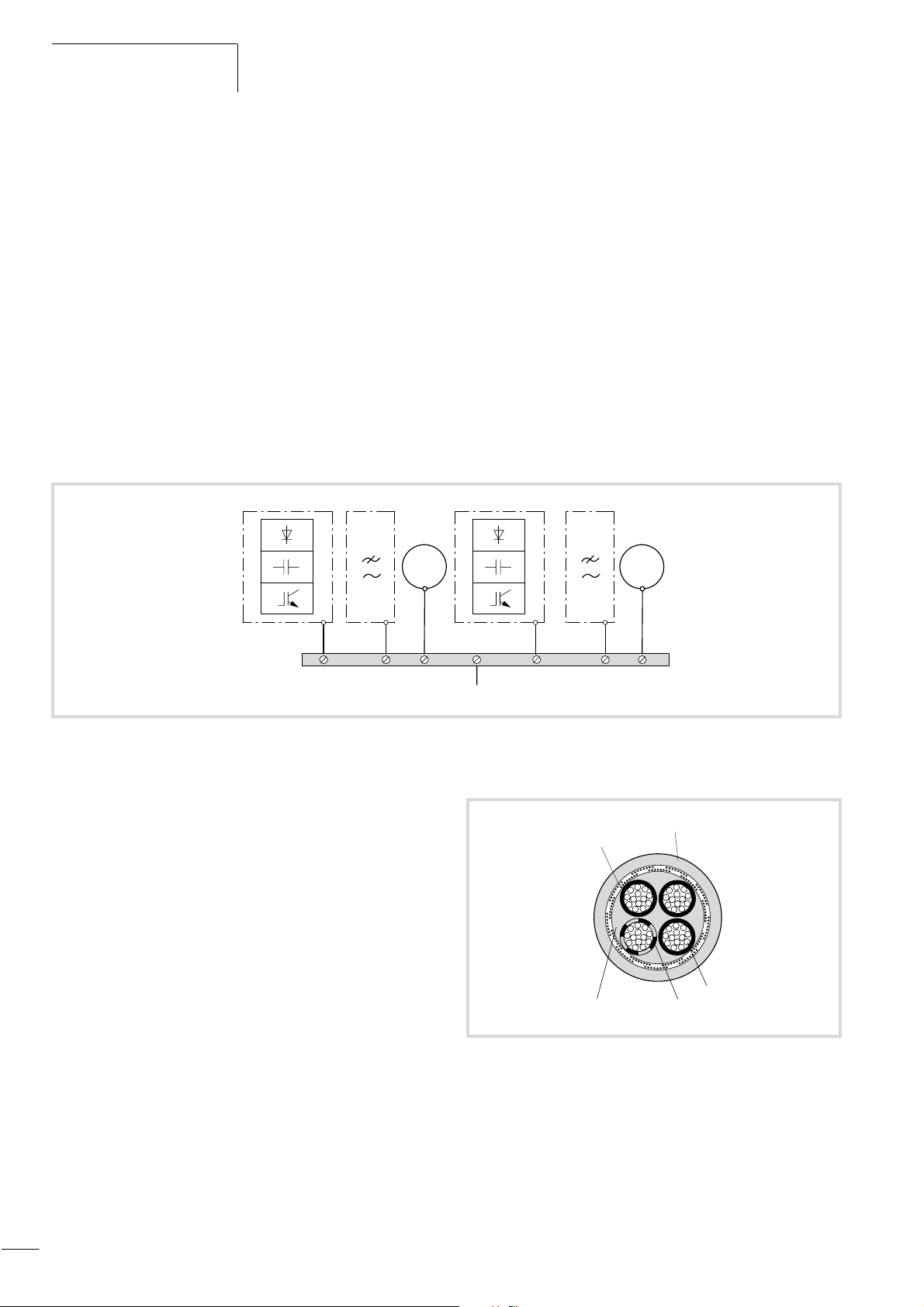
To ensure an EMC-compliant setup, connect all metallic
components of the devices and of the control cabinet with each
other using a large cross-section conductor with good HF
conducting properties. Do not make connections to painted
surfaces (Eloxal, yellow-passivized). If there is no alternative, use
contact and scraper washers to ensure contact with the base
metal. Connect mounting plates to each other, and the cabinet
doors with the cabinet, using contacts with large surface areas and
short HF wires.
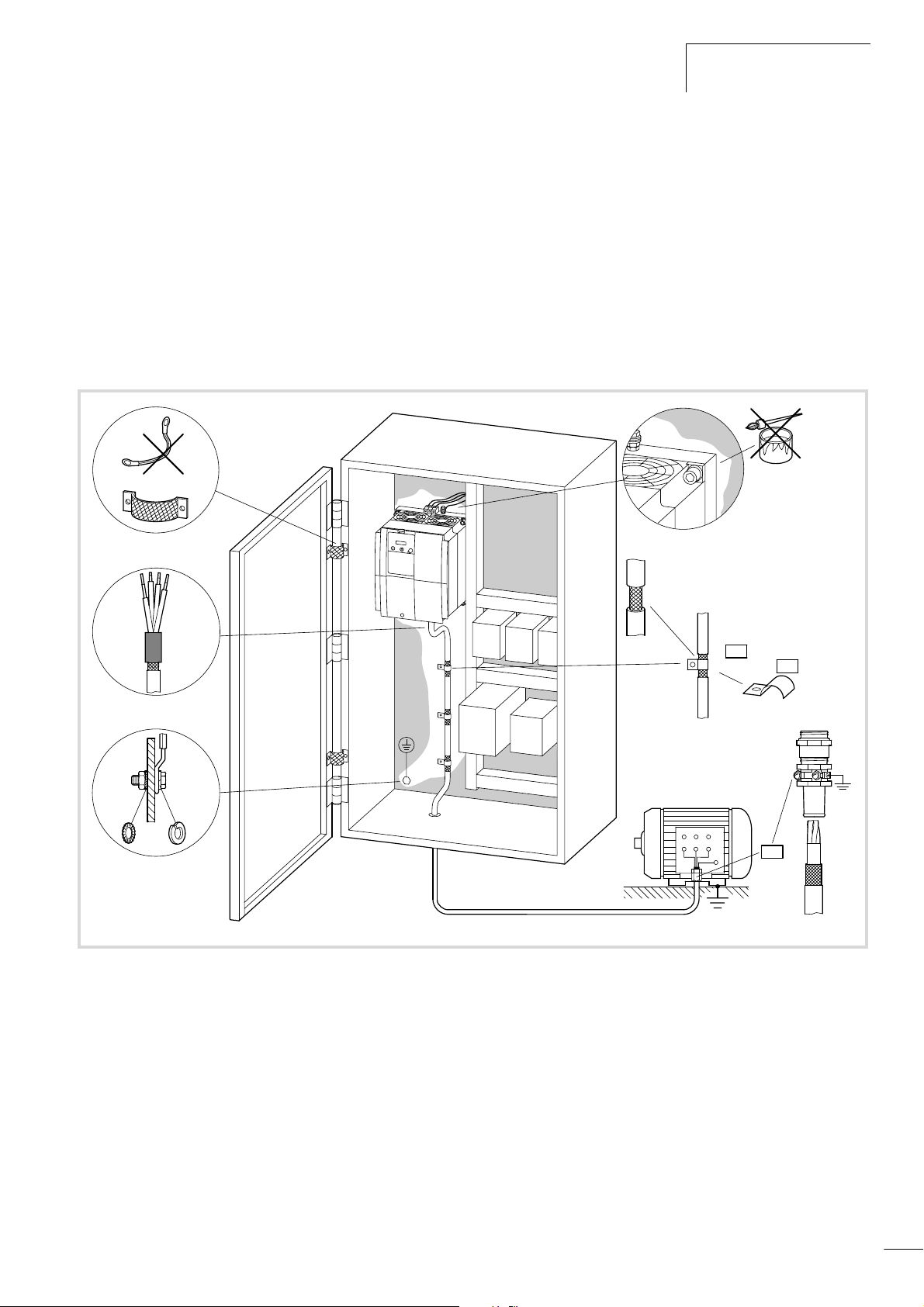
The figure below provides an overview of all EMC measures.
PE
Figure 13: EMC-compliant setup
PES
W2
U2
V2
U1
W1
V1
PE
PES
PES
23
Page 27
Installation
efesotomasyon.com - Klockner Moeller - inverter
01/02 AWB8230-1413GB
Fit additional RFI filters or mains filters and frequency inverters as
closely as possible to each other and on a single metal mounting
plate.
Lay cables in the control cabinet as near as possible to the earth
potential. Cables that hang freely act as antennae.
To prevent transfer of electromagnetic energy, lay interferencesuppressed cables (e.g. the mains supply line before the filter) and
signal lines as far away as possible (at least 10 cm) from
HFconducting cables (e.g. mains supply cable after a filter, motor
power cable). This applies especially where cables are routed in
parallel. Never use the same cable duct for interferencesuppressed and HF cables. Where crossovers are unavoidable,
cables should always cross at right angles to each other.
Z1G1 Gn Zn
M1
M
3h
Never lay control or signal cables in the same duct as power
cables. Analog signal cables (for measured values, setpoints and
correction values) must be screened.
Earthing
Connect the base plate (mounting plate) with the protective earth
using a short cable. Lay all conducting components (frequency
inverter, mains filter, motor filter, mains choke) with an HF wire,
and the protective conductor in a star configuration from a central
earthing point. This achieves the best results.
Make sure that the earthing measures have been correctly
implemented (a fig. 14). No other device which has to be
earthed should be connected to the earthing terminal of the
frequency inverter. If more than one frequency inverter is used, the
earthing cables should not form a closed loop.
Mn
M
3h
PE
PE
Figure 14: Star-type point-to-point earthing
PE
Screening
Unscreened cables behave like antennae, i.e. they act as
transmitters and receivers. To ensure EMC-compliant connection,
screen all interference-emitting cables (frequency inverter/motor
output) and interference-sensitive cables (analog setpoint and
measured value cables).
The effectiveness of the cable screen depends on a good screen
connection and a low screen impedance. Use only screens with
tinned or nickel-plated copper braiding, braided steel screens are
unsuitable. The screen braid must have an overlap ratio of at least
85 percent and an overlap angle of 90°.
PE
PE
e
a
e
Figure 15: Sample motor cable
a Copper screen braid
b PVC outer sheath
c Drain wire (copper)
d PVC core insulation
3 x black, 1 x green/yellow
e Textile braid and PVC inner
b
c
d
24
Page 28
01/02 AWB8230-1413GB
efesotomasyon.com - Klockner Moeller - inverter
EMC compliance
The screened cable between frequency inverter and motor should
be as short as possible. Connect the screen to earth at both ends
of the cable using a connection with a large contact surface.
Lay the cables for the supply voltage separately from the signal
cables and control cables.
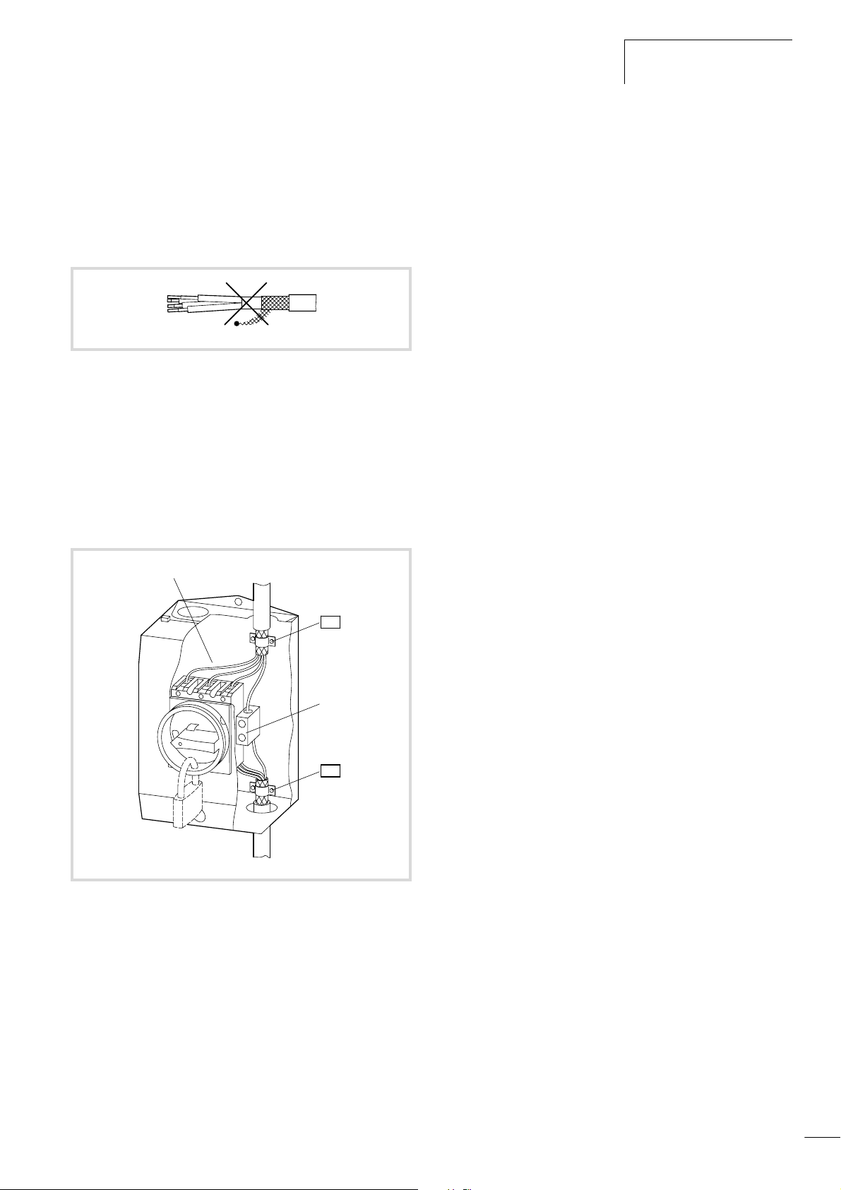
Never unravel the screening or use pigtails to make a connection.
Figure 16: Inadmissible screen grounding (pigtails)
If contactors, maintenance switches, motor protection relays,
motor chokes, filters or terminals are installed in the motor
cabling, interrupt the screen near these components and connect
it to the mounting plate (PES) using a connection with a large
contact surface. The free, unscreened connecting cables should
not be longer than about 100 mm.
Example: Maintenance switch
In an EMC-compliant control cabinet (metal-enclosed, damped to
about 10 dB), the motor cables do not need to be screened
provided that the frequency inverter and motor cables are spatially
separated from each other and arranged in a separate partition
from the other control system components. The motor cable
screening must then be connected with a large surface area
connection at the control cabinet (PES).
The control cable and signal (analog setpoint and measured value)
cable screens must be connected only at one cable end. The screen
connection must have a large contact surface a low impedance.
Digital signal cable screens must be connected at both cable ends,
also with large-surface, low-resistance connections.
a
PES
b
PES
Figure 17: Maintenance switch, e.g. T… in an enclosure
a Metal plate
b Insulated PE terminal
25
Page 29

Installation
efesotomasyon.com - Klockner Moeller - inverter
Electrical connection
This section describes how to connect the motor and the supply
voltage to the power terminals, and the signal cables to the
control terminals and the signalling relay.
Warning!
Carry out the wiring work only after the frequency inverter
has been correctly mounted and secured. Otherwise,
there is a danger of electrical shock or injury.
Warning!
Carry out wiring work only under zero voltage conditions.
Warning!
Use only cables, residual-current circuit breakers and
contactors with a suitable rating. Otherwise there is a
danger of fire.
01/02 AWB8230-1413GB
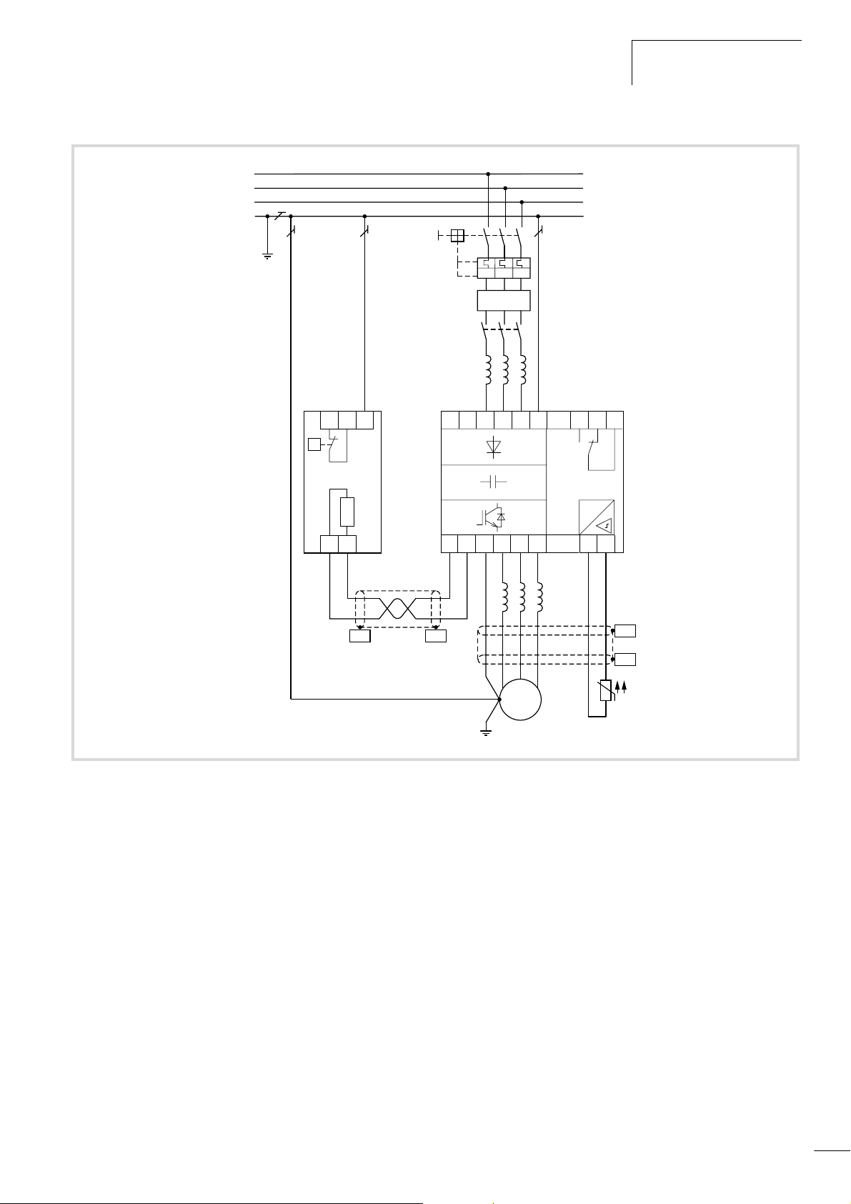
The following illustration shows an overview of the connections.
26
Page 30
01/02 AWB8230-1413GB
efesotomasyon.com - Klockner Moeller - inverter
Electrical connection
a
L1
L2
L3
PE
3 h 400 V, 50/60 Hz
b
I > I > I >
c
FI
d
e
j
T1 T2 PE
i
L1 L2
L3 PE K14 K12 K11
#
f
VW
U
PE
PES
Figure 18: Power connection
a Network configuration, mains voltage, mains frequency
Interaction with p.f. correction systems
b Fuses and cable cross-sections
c Protection of persons and domestic animals with residual-current circuit
breakers
d Mains contactor
e Mains choke, radio interference filter, line filter
f Mounting, installation
Power connection
EMC measures
Example of circuits
g
PES
M
i
3
˜
g Motor filter
du/dt filter
Sinusoidal filter
h Motor cables, cable length
i Motor connection
Parallel operation of multiple motors on a single frequency inverter
j Braking resistors, braking units
DC link coupling
DC supply
PES
h
PES
i
27
Page 31
Installation
efesotomasyon.com - Klockner Moeller - inverter
01/02 AWB8230-1413GB
Connecting the power section
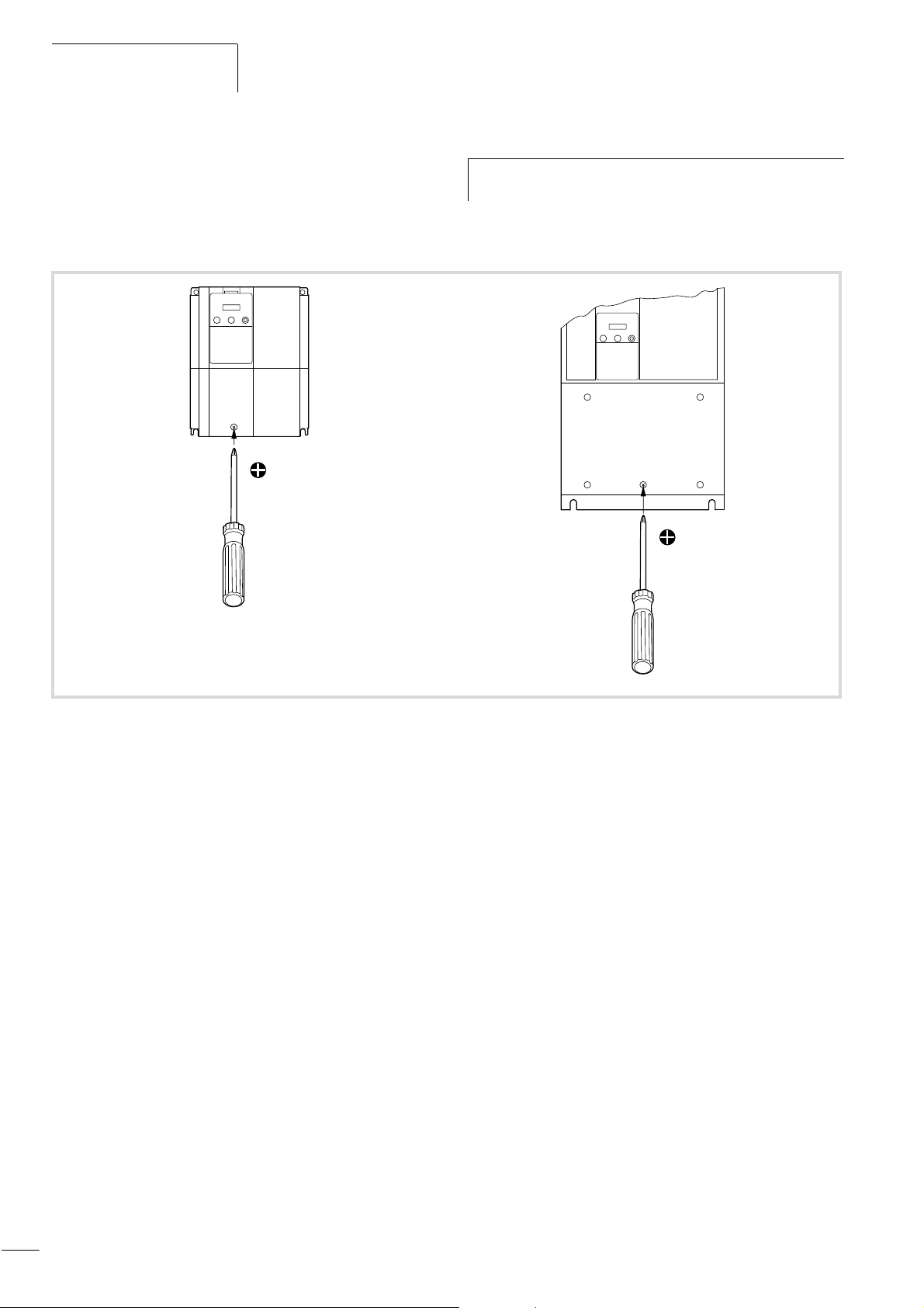
To connect the supply voltage, the motor cables and the signal
relay terminals, open the front cover.
1
Complete the following steps with the specified tools and
h
without the use of force.
Opening the terminal shroud
X Loosen the screw
1
Figure 19: Loosening the screw
28
Page 32
01/02 AWB8230-1413GB
efesotomasyon.com - Klockner Moeller - inverter
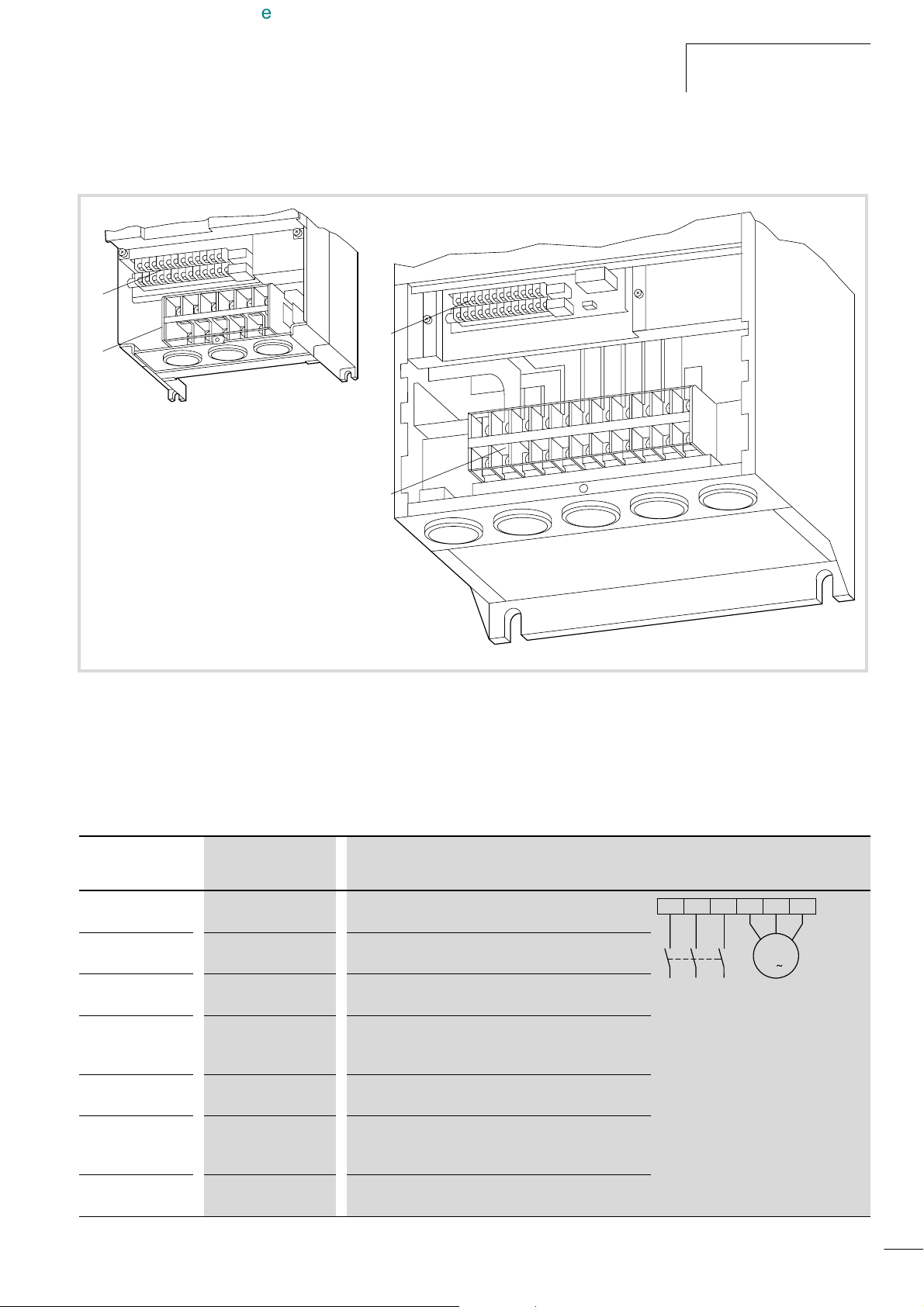
X Pull the terminal shroud upwards to remove it.
a
b
Electrical connection
a
b
Figure 20: View of the power and control signal terminals
a Control signal terminals
b Power terminals
Arrangement of power terminals
Table 3: Description of the power terminals
Terminal
designation
L1, L2, L3 Supply voltage (mains
U, V, W Frequency inverter
L+, DC+
DC+, DC–
BR, DC+
R0, T0
e, PE
Function Description
Three-phase mains voltage: Connection to: L1, L2, L3
voltage)
Connection of a three-phase motor
output
External DC choke Normally, the terminals L+ and DC+ are fitted with a
jumper. If a DC link choke is used, remove this jumper.
DC link These terminals are used for connecting an optional
braking resistor and for DC linking and supplying DC
power to multiple frequency inverters.
External braking
resistor
Control electronics
supply voltage
These terminals are used for connecting an optional
external braking resistor.
The voltage supply for the control electronics is provided
internally through connector J51 by tapping off L1 and L3.
The control electronics can also be supplied externally.
Earthing Enclosure earthing (prevents dangerous voltages on the
enclosure in the event of a malfunction)
L3L2L1 U V W
M
3
D
29
Page 33
Installation
efesotomasyon.com - Klockner Moeller - inverter
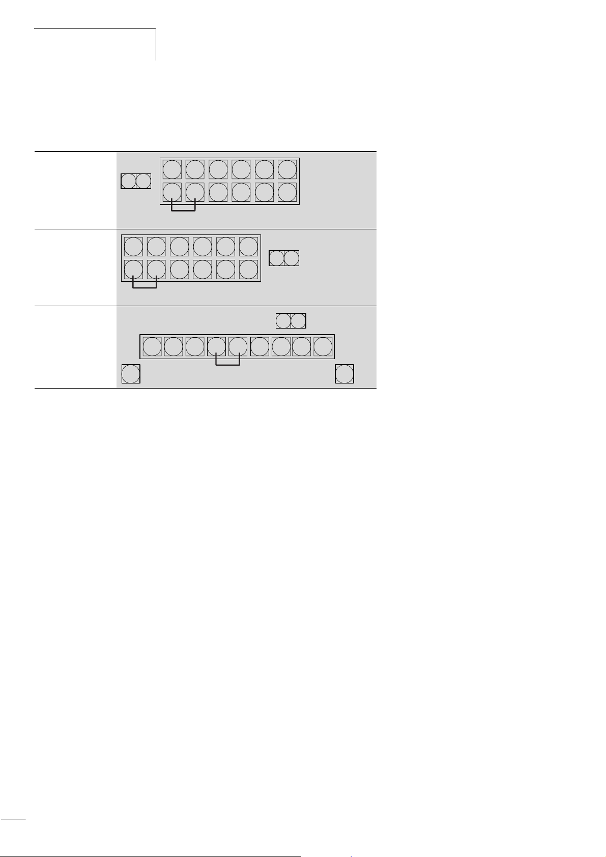
The arrangement of the power terminals is shown in the figure
below.
Table 4: Arrangement of the power terminals
DF6-340-11K
DF6-340-15K
L2
L1
T0R0
DC+
L+
UVW
L3
DC–
BR
ee
PE
a
DF6-340-18K5
...
DF6-340-75K
L2
L1
DC+
L+
UVW
L3
DC–
BR
ee
PE
PE
a
DF6-340-90K
...
DF6-340-132K
DC+
L+L3L2L1
DC–
01/02 AWB8230-1413GB
PE
T0R0
T0R0
UVW
ee
PE
a
a Internal connection. Remove if a DC link choke is used.
PE
30
Page 34
01/02 AWB8230-1413GB
efesotomasyon.com - Klockner Moeller - inverter
Electrical connection
Power terminal connection
Warning!
Select a frequency inverter according to the available
supply voltage (a section “Technical Data”, page 159):
• DF6: Three-phase 400 V (342 to 528 V g 0%)
Lay the cables for the power section separately from the signal
cables and control cables.
Warning!
Never connect mains voltage to the output terminals U, V
and W. Danger of electrical shock or fire.
The connected motor cables must be screened. The maximum
cable length must not exceed 50 m. With larger cable lengths, a
motor choke is required for d /dt limitation
If the cable leading from the frequency inverter to the motor is
Warning!
Each phase of the supply voltage for the frequency
inverter must be protected with a fuse (danger of fire).
longer than about 10 m, the fitted thermal overload relays
(bimetallic relays) may malfunction due to high frequency
harmonics. Install a motor filter on the output of the frequency
inverter in this case.
Warning!
Tightening torques and conductor cross-sections
Make sure that all power cables are correctly tightened in
the power section.
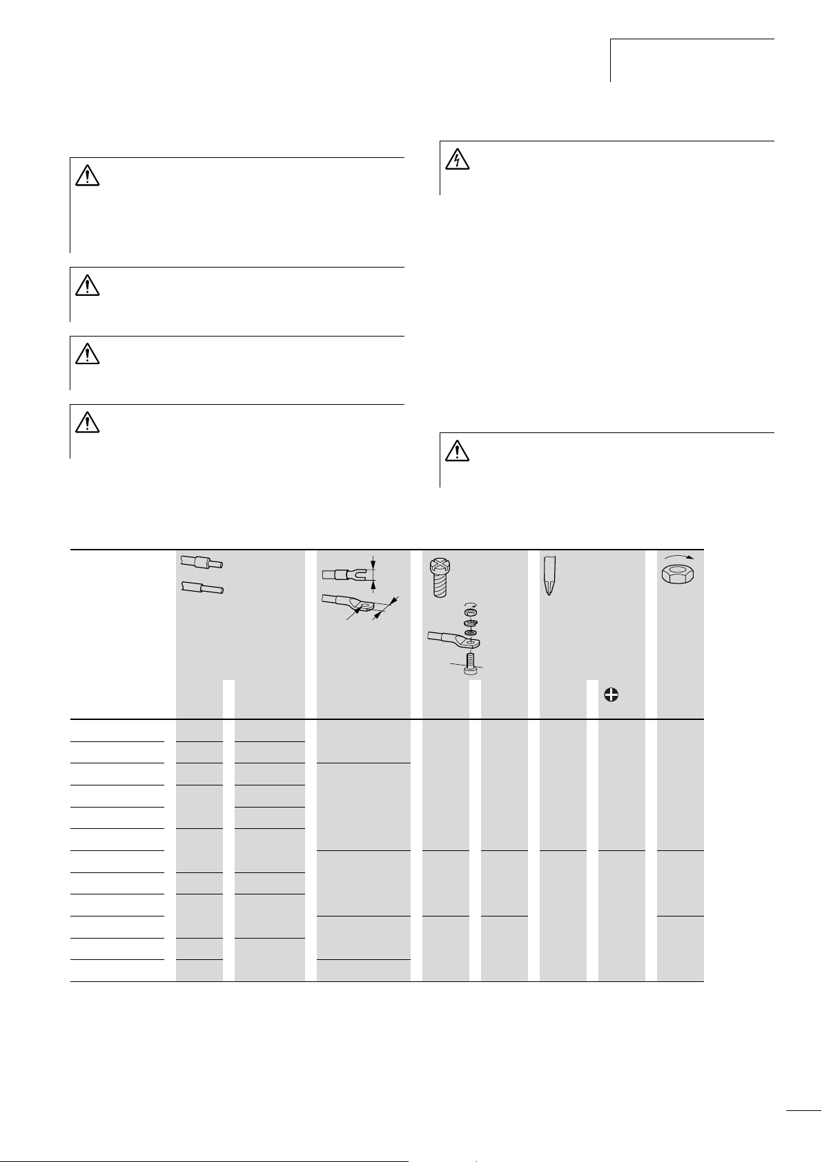
X Tighten the cable connections according to table 5.
Table 5: Tightening torques and conductor cross-sections for the power terminals
L1, L2, L3
L+, DC+, DC–, BR
U, V, W, PE
w
o
w
Warning!
The frequency inverter must be earthed. Danger of
electrical shock or fire.
Laying the cables
Warning!
To prevent inadvertent loosening, tighten the screws on
the terminals sufficiently (a table 5).
DF6-340- mm
11K 6 8 < 17 M6 6.5 4.9 1 –
15K
18K5
22K
30K
37K
45K
55K
75K
90K
110K
132K
2
AWG mm O Nm Nm
10 6
16 6 < 18
25 4
3
35 1
< 23 M8 8.5 – – 8.8
50 1/0
2 x 35 2 x 1 (75 °C)
< 29 M10 10.5 13.7
2 x 50 2 x 1/0
2 x 70 < 40
31
Page 35
Installation
efesotomasyon.com - Klockner Moeller - inverter
01/02 AWB8230-1413GB
PES
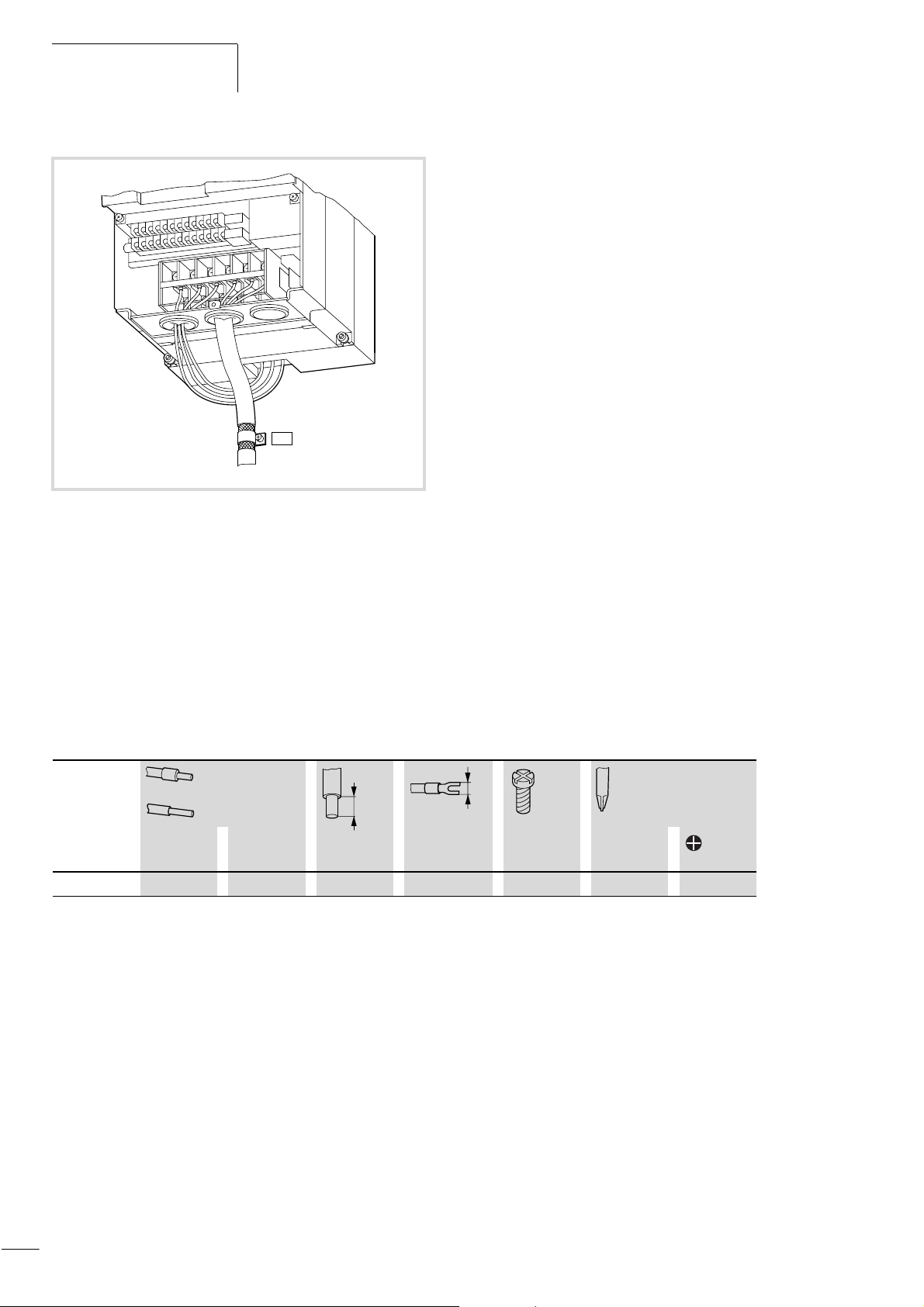
Figure 21: Cable connection to the power terminals
Connecting the supply voltage
X Connect the supply voltage to the power terminals L1, L2, L3
and PE:
Connecting external supply voltage for the control electronics
If you also want to parameterize the DF6 frequency inverter with
the power supply switched off, connect an external power supply
(400 V ~) to terminals R0 and T0. Proceed as follows:
Table 6: Tightening torques and conductor cross-sections of terminals R0,T0
R0, T0
2
mm
AWG mm Nm
DF6-340-... 1.5 to 2.5 16 to 14 8 to 10 9 M4 1.2 to 1.38 1
w
32
Page 36
01/02 AWB8230-1413GB
efesotomasyon.com - Klockner Moeller - inverter
Electrical connection
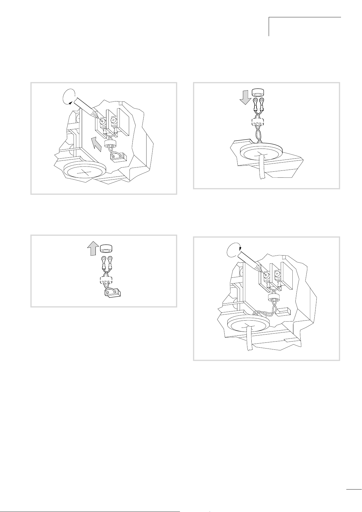
X Remove the screws on terminals R0 and T0 and remove
connector J51.
R0
Figure 22: Remove the connection of J51 to R0 and T0
X Remove the ferrite rings from both cables.
T0
J51
X Push the ferrite rings onto both of the external supply voltage
cables (400 V ~).
Figure 24: Push on the ferrite rings
X Screw on the cables of the external voltage supply to the
terminals R0 and T0.
Figure 23: Remove the ferrite rings
R0
T0
J51
Figure 25: Connecting the external supply voltage
33
Page 37
Installation
efesotomasyon.com - Klockner Moeller - inverter
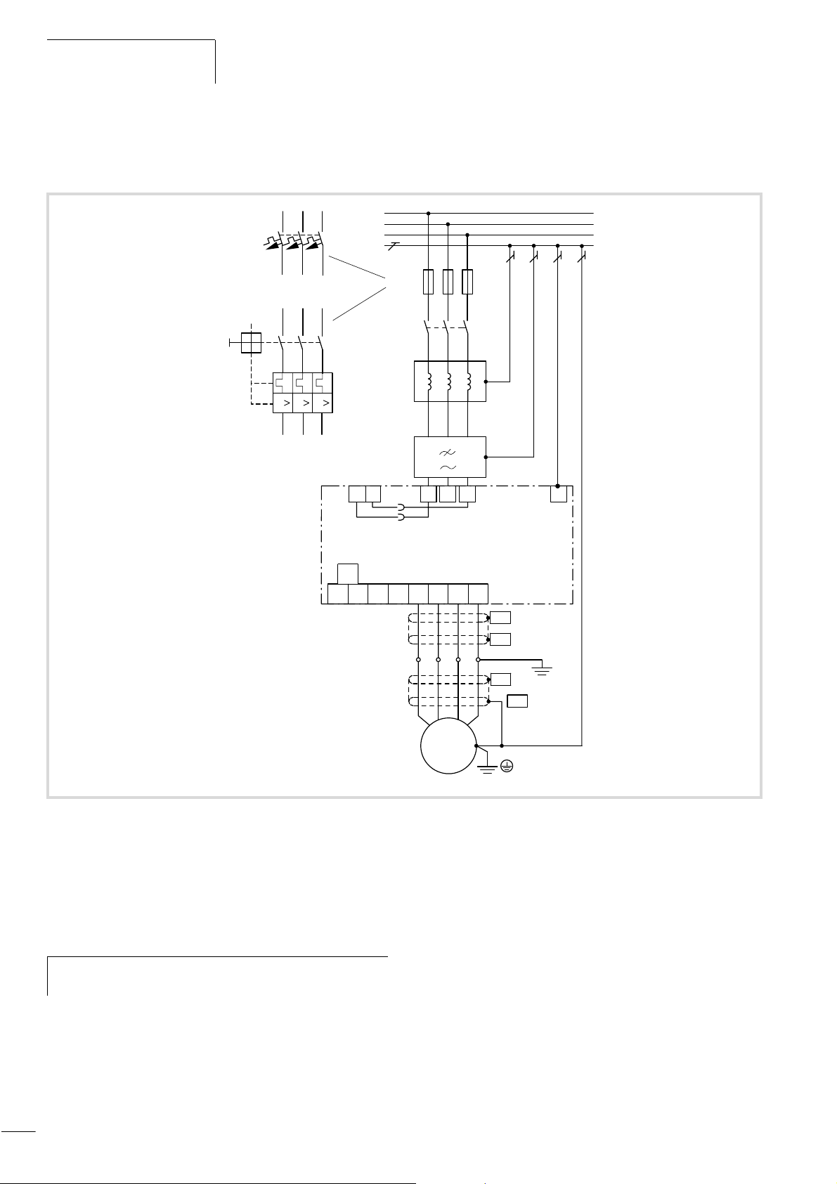
Connecting the motor cable
X Connect the motor cable to the U, V, W and PE terminals:
01/02 AWB8230-1413GB
Q1
RO TO
DC+
L1
L2
L3
PE
Q1/F1
K1M
L1
Z1
J51
DC–L+U
X1
L1 L2 L3
L1 L2 L3
L1 L2 L3
DF6-340
W
V
PE
PE
PE
PEBR
PES
PES
PES
PES
2
46
F1
1
35
1
35
I II
2
46
Figure 26: Power terminal connection
F1, Q1:Line protection
K1M: Mains contactor
L1: Mains choke
Z1: RFI filter
Observe the electrical connection data (rating data) on
h
the rating label (nameplate) of the motor.
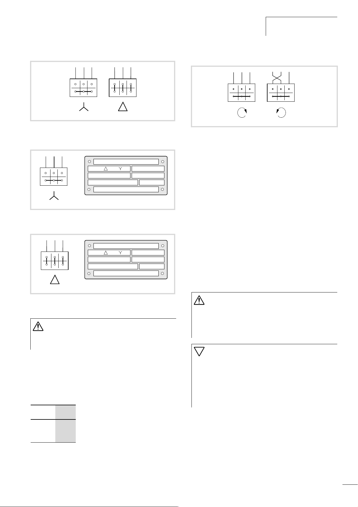
The stator winding of the motor can be connected in a star or delta
configuration in accordance with the rating data on the
nameplate.
34
M1
M
3 ~
Page 38
01/02 AWB8230-1413GB
efesotomasyon.com - Klockner Moeller - inverter
Electrical connection
U1 V1 W1
W2 U2 V2
Figure 27: Connection types
U1 V1 W1
W2 U2 V2
Figure 28:
Example in motor star circuit
U1 V1 W1
W2 U2 V2
U1 V1 W1
W2 U2 V2
/ 400 V230
11S1
kW
rpm
1410 50 Hz
/ 690 V400
11S1
kW
rpm
1410 50 Hz
38 / 22 A
ϕ
cos
0.67
22 / 13 A
ϕ
cos
0.67
U1 V1 W1
W2 U2 V2
FWD
U1 V1 W1
W2 U2 V2
REV
Figure 30: Direction of rotation, change of direction
In frequency inverter operation, you can reverse the direction of
rotation of the motor shaft by:
• swapping two of the motor’s phase connections.
• actuating terminal FW (clockwise) or 5
(default: REV = anticlockwise)
• applying a control command through the interface or fieldbus
interface connection
The speed of a three-phase motor is determined by the number of
pole pairs and the frequency.
The output frequency of the DF6 frequency inverter is indefinitely
variable from 0.1 to 400 Hz.
Pole-changing three-phase motors (Dahlander pole-changing
motors), rotor-fed three-phase commutator shunt motors (slipring
rotor) or reluctance motors, synchronous motors and servo motors
can be connected, provided they are approved for use with
frequency inverters by the motor manufacturer.
Figure 29:
Example in motor delta circuit
Warning!
If motors are used whose insulation is not suitable for
operation with frequency inverters, the motor may be
destroyed.
If you use a motor filter or a sinusoidal filter here, the rate of
voltage rise can be limited to values of about 500 V/ms
(DIN VDE 0530, IEC 2566).
By default, the DF6 frequency inverters have a clockwise rotation
field. Clockwise rotation of the motor shaft is achieved by
connecting the motor and frequency inverter terminals as follows:
Motor DF6
U1
V1
W1
U
V
W
Warning!
The operation of a motor at speeds above its rated speed
(indicated on the nameplate) can cause mechanical
damage to the motor (bearings, unbalance) and the
machinery to which it is connected, and can lead to
dangerous operating conditions.
Caution!
Uninterrupted operation in the lower frequency range
(less than about 25 Hz) can lead to thermal damage
(overheating) of self-ventilated motors. Possible
countermeasures include over-dimensioning or external
cooling independent of motor speed.
Observe the manufacturers recommendations for
operating the motor.
35
Page 39
Installation
efesotomasyon.com - Klockner Moeller - inverter
Parallel connection of motors to a single frequency inverter
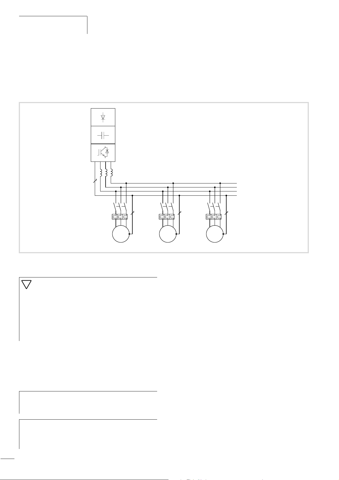
DF6 frequency inverters can control several parallel-connected
motors. If the motors are to run at different speeds, this must be
implemented through the number of connected pole pairs and/or
the gear transmission ratio.
01/02 AWB8230-1413GB
K1M
F1
M1
Figure 31: Parallel connection of multiple motors
U1 V1 W1
M
3
˜
K2M
F2
M2
Caution!
If a frequency inverter controls a number of motors in
parallel, the contactors for the individual motors must be
designed for AC
-3 operation. Do not use the mains
contactors listed in table in the appendix (section “Mains
contactors”, page 165). These mains contactors are
designed only for the mains (primary) currents of the
frequency inverter. If they are used in multiple-motor
circuits, their contacts may weld.
Connecting motors inparallel reduces the load resistance at the
frequency inverter output, reduces the total stator inductivity is
and increases the leakage capacitance. As a result, the current
distortion is larger than it is in a single-motor circuit. To reduce the
current distortion, chokes or sinusoidal filters can be connected at
the frequency inverter output.
K3M
U1 V1 W1
M
3
˜
F3
M3
U1 V1 W1
M
3
˜
If motors with widely differing ratings (for example 11 kW and
30 kW) are connected in parallel to the output of a frequency
inverter, problems may arise during starting and at low speeds.
Motors with a low rating may be unable to develop the required
torque. This is due to the relatively high ohmic resistances of their
stators. They require a higher voltage during the start phase and
at low speeds.
The current consumption of all connected motors must
h
not exceed the rated output current I
of the frequency
2N
inverter.
Electronic motor protection can not be used when
h
operating the frequency inverter with a several connected
motors. You must however, protect each motor with
thermistors and/or overload relays.
36
Page 40
01/02 AWB8230-1413GB
efesotomasyon.com - Klockner Moeller - inverter
Electrical connection
Motor cable
To ensure electromagnetic compatibility, use only screened motor
cables. The length of the motor cable and the associated use of
further components has an influence on the motor control mode
and the performance characteristics. In parallel operation (multiple
motors connected to the frequency inverter output), the resulting
cable lengths l
l
= SlM x Wn
res
SlM: Sum of all motor cable lengths
: Number of motor circuits
n
M
With long motor cables, the leakage currents caused by
h
must be calculated:
res
M
parasitic cable capacities can cause the “earth fault”
message. In this case, motor filters must be used.
Keep the motor cables as short as possible as it will positively
influence the drive’s characteristics.
Motor choke, du/dt
filters, sinusoidal filters
Motor chokes compensate for capacitive currents with long motor
cables and with grouped drives (multiple connection of parallel
drives to a single inverter).
The use of motor chokes is recommended (observe the
manufacturers instructions):
Bypass operation
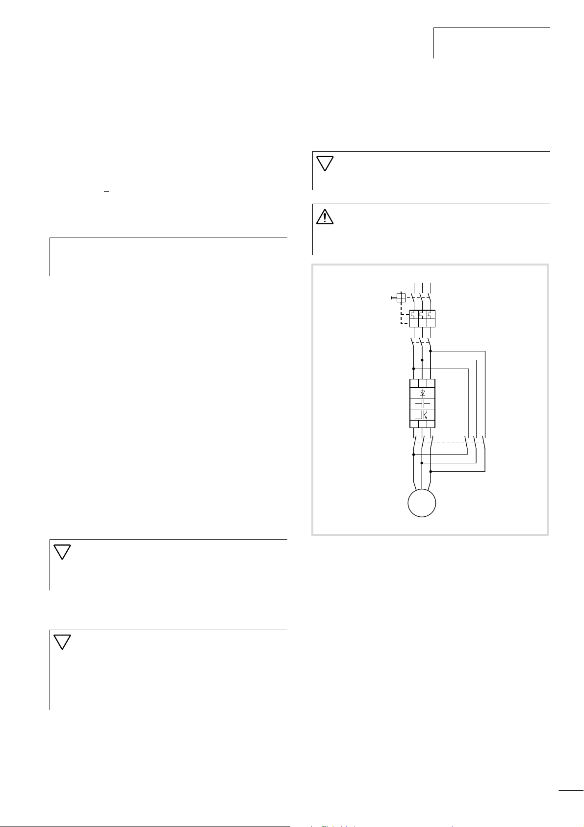
If you want to have the option of operating the motor with the
frequency inverter or directly from the mains supply, the incoming
supplies must be mechanically interlocked:
Caution!
A changeover between the frequency inverter and the
mains supply must take place in a voltage-free state.
Warning!
The frequency inverter outputs (U, V, W) must not be
connected to the mains voltage (destruction of the device,
risk of fire).
L2
L3
L1
Q1
>
I>I>I
K1M
L1 L2 L3
• for grouped drives
• for the operation of three-phase current asynchronous motors
with maximum frequencies greater than 200 Hz,
• for the operation of reluctance motors or permanently excited
synchronous motors with maximum frequencies above 120 Hz.
du/dt filters are used for limiting the rate of voltage rise at the
motor terminals to values below 500 V/ms. They should be applied
for all motors with unknown or insufficient insulation withstand
voltage.
Caution!
During the engineering phase, keep in mind that the
voltage drop across motor filters and du/dt filters can be
up to 4 % of the frequency inverter’s output voltage.
When sinusoidal filters are used, the motor supply voltage and
current are almost sinusoidal.
Caution!
During the engineering phase, keep in mind that the
sinusoidal filter must be matched to the output voltage
and to the frequency inverter’s pulse frequency.
The voltage drop on the sinusoidal filter can be up to
15 % of the frequency inverter’s output voltage.
G1
S1
M1
Figure 32: Bypass motor control
UVW
M
3h
37
Page 41
Installation
efesotomasyon.com - Klockner Moeller - inverter
Connecting the control signal terminals
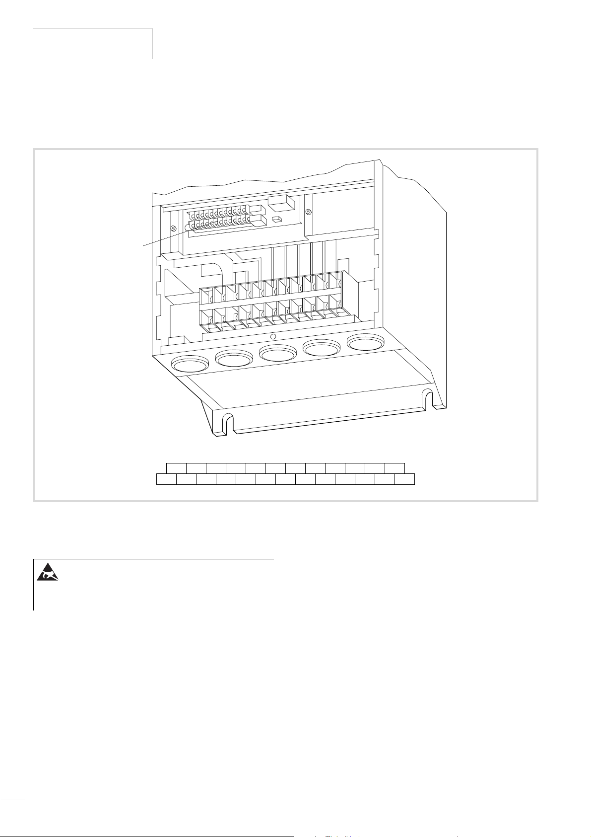
The figure below shows the arrangement of the individual control
signal terminals.
a
01/02 AWB8230-1413GB
Figure 33: Location of the control signal terminals
a Control signal terminals
hO2AMFMTHFW54321K14
L O OI AMI P24 PLC CM1 K33 K34 K23 K24 K11 K12
ESD measures
Discharge yourself on an earthed surface before touching
the frequency inverter and its accessories. This prevents
damage to the devices through electrostatic discharge.
38
Page 42
01/02 AWB8230-1413GB
efesotomasyon.com - Klockner Moeller - inverter
Electrical connection
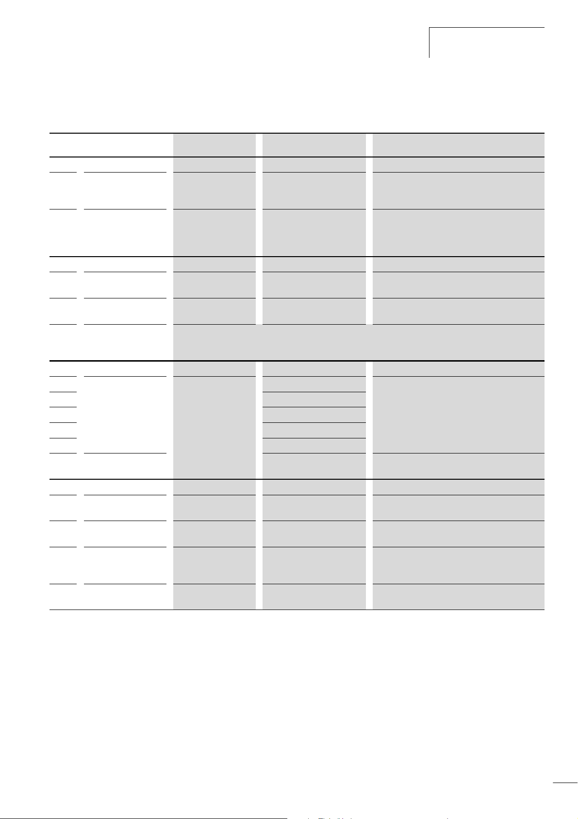
Function of the control signal terminals
Table 7: Meaning of the control signal terminals
No. Function
Supply voltages
H Setpoint voltage output +10 V H – Supply voltage for external setpoint potentiometer.
P24 Control voltage output
Reference potentials
CM1 Reference potential 0 V – Reference potential terminals 1 to 5, FM, FW,
L Reference potential
PLC Common connection,
terminals 1 to 5 and FW
Digital inputs
1 Digital input HIGH = +12 to +27 V
2
3
4
5
FW Digital input, clockwise
operation
Analog inputs
OAnalog input 0 to +10 V H Frequency setpoint value
OI Analog input
O2 Analog input frequency
setpoint
TH Thermistor input
Level WE Technical data, description
Load carrying capacity: 20 mA
Reference potential: Terminal L
+24 V H – Supply voltage for actuation of digital inputs 1 to 5
and FW.
Load carrying capacity: 100 mA
Reference potential: Terminal CM1
TH and P24
0 V – Reference potential, terminals AM, AMI, H, O,
OI and O2
By default, the frequency inverters are supplied with a link between PLC and CM1, so that the potential on terminal
PLC – and therefore on the digital inputs that are not energized – is 0 V (positive logic). If PLC is applied to P24,
the control logic is positive.
RST = reset PNP logic, configurable, Ri=4.7kO
LOW = 0 to +3 V
4 to 20 mA Frequency setpoint value
–10 V to +10 V H – Resolution: 12-bit
AT = analog input changeover
FF2 = fixed frequency 2
FF1 = fixed frequency 1
REV = anticlockwise operation
– Ri=4.7kO
(0 to 50 Hz)
(0 to 50 Hz)
– Minimum thermistor rating: 100 mW
Reference potential: Terminal CM1
Reference potential: Terminal CM1
Ri = 10 kO
Reference potential: Terminal L
RB = 250 O
Reference potential: Terminal L
Input impedance: 10 kO
Reference potential: Terminal L
Reference potential: Terminal CM1
39
Page 43
Installation
efesotomasyon.com - Klockner Moeller - inverter
01/02 AWB8230-1413GB
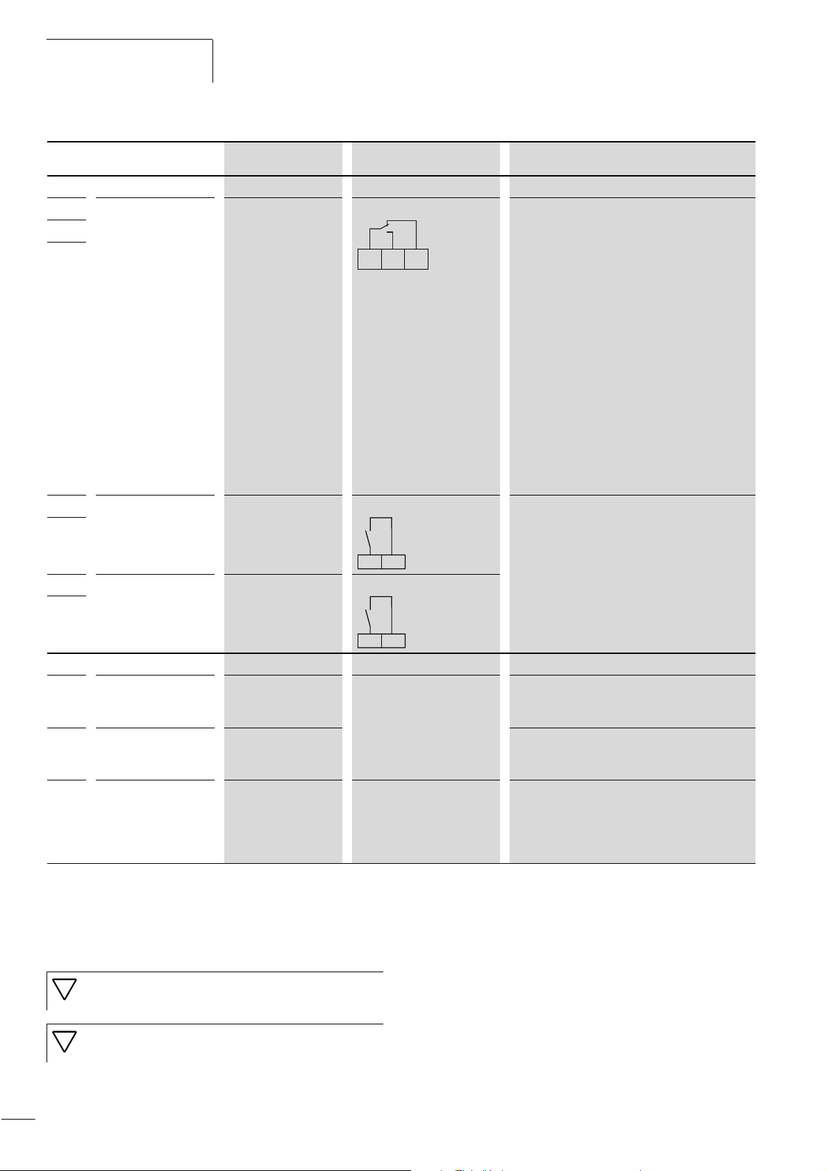
No. Function
Relay outputs
K11 Programmable relay
K12
K14
K23 Programmable relay
K24
K33 Programmable relay
K34
output, changeover
contact
output, make contact
output, make contact
Level WE Technical data, description
AL = fault message Default settings:
• Run signal: K11K14 closed.
• Fault signal or power supply switched off:
K12K11 K14
– FA1 = frequency reached Characteristics of the contacts:
K23 K24
– RUN = Run signal
K11-K12 closed
Characteristics of the relay contacts:
•K11K14
– Maximum 250 V AC/2 A (resistive) or
0.2 A (inductive, p.f. = 0.4);
minimum 100 V AC/10 mA
– Maximum 30 V DC/8 A (resistive) or
0.6 A (inductive, p.f. = 0.4);
minimum 5 V DC/100 mA
•K11K12
– Maximum 250 V AC/1 A (resistive) or
0.2 A (inductive, p.f. = 0.4);
minimum 100 V AC/10 mA
– Maximum 30 V DC/1 A (resistive) or
0.6 A (inductive, p.f. = 0.4);
minimum 5 V DC/100 mA
• Maximum 250 V AC/5 A (resistive) or
1 A (inductive, p.f. = 0.4);
• Maximum 30 V DC/5 A (resistive) or
1 A (inductive, p.f. = 0.4);
• minimum 5 V DC/100 mA
K33 K34
Analog outputs
AM Voltage output 0 to +10 V H Frequency actual value Resolution: 8-bit
Load carrying capacity: 2 mA
Reference potential: Terminal L
AMI Current output
FM Frequency output
Control signal terminal wiring
Wire the control signal terminals as appropriate for their
application. For instructions for changing the function of the
control signal terminals, see section “Programming the Control
4 to 20 mA Resolution: 8-bit
F 250 O
R
B
Reference potential: Terminal L
0 to +10 V H Frequency actual value
(0 to 50 Hz)
Configurable, monitored DC voltage; 10 V
corresponds to set end frequency (50 Hz).
Accuracy: g5 % from final value
Load carrying capacity: 1.2 mA
Reference potential: Terminal CM1
Use twisted or screened cables for connecting to the control signal
terminals. Earth the screen on one side with a large contact area
connection near the frequency inverter. The cable length should
not exceed 20 m. For longer cables, use a suitable signal amplifier.
Signal Terminals”, page 53.
Caution!
Never connect terminal P24 with terminals L, H, OI or FM.
Caution!
Never connect terminal H with terminal L.
40
Page 44
01/02 AWB8230-1413GB
efesotomasyon.com - Klockner Moeller - inverter
Electrical connection
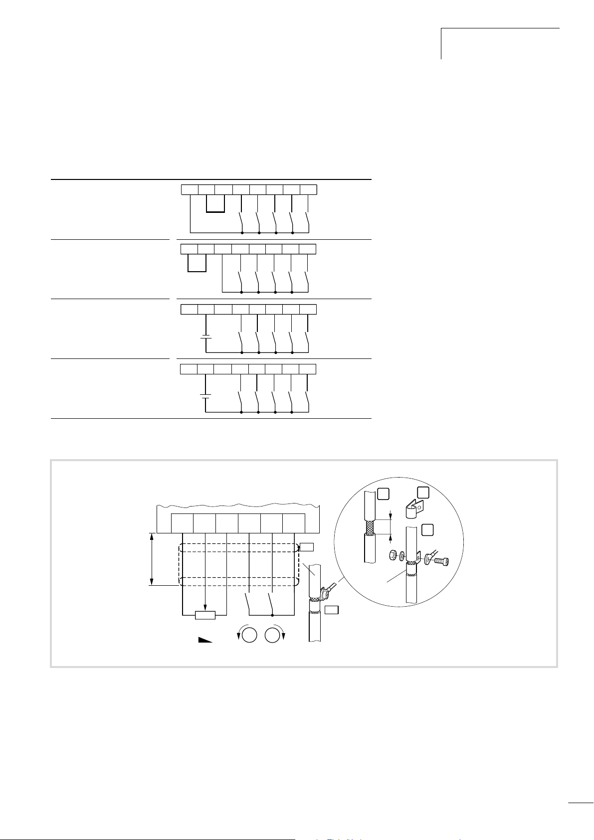
Actuating the digital inputs
The DF6 has five digital inputs, which are connected internally
with terminal PLC. By default, power is supplied through the
internal 24 V supply. For this purpose, terminals PLC and CM1 are
connected with a jumper. If the digital inputs are to be supplied
from an external source, remove this jumper.
Actuating the digital inputs with
internal supply voltage and
positive logic (default)
Actuating the digital inputs with
internal supply voltage and
negative logic
Actuating the digital inputs with
external supply voltage and
positive logic
Actuating the digital inputs with
external supply voltage and
negative logic
–
+
+
–
The digital inputs can be operated both with positive (default
setting) and with negative logic. To set it to negative logic, remove
the jumper between terminals PLC and CM1 and connect
terminals PLC and P24 with this jumper. If you are using an
external power supply, you can connect the negative pole (positive
logic) or the positive pole (negative logic) with terminal PLC.
54321CM1PLCP24
54321CM1PLCP24
54321CM1PLCP24
54321CM1PLCP24
The figure below shows a sample protective circuit for the control
signal terminals
H O
F 20 m
4K7
R1 REV FWD
Figure 34: Control terminal connection (factory setting)
5
L
FW
M
M
P24
PES
PES
PE
1
15
ZB4-102-KS1
2
3
Cu 2.5 mm
2
M4
41
Page 45
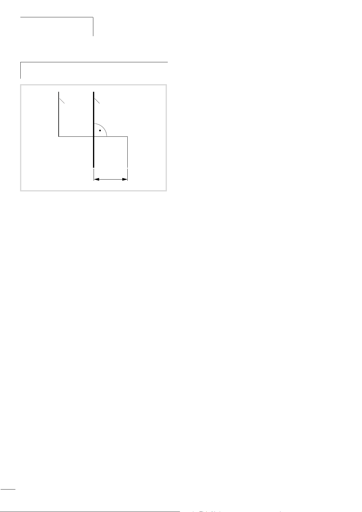
Installation
efesotomasyon.com - Klockner Moeller - inverter
Route the control and signal cables separately from the
h
mains and motor cables.
01/02 AWB8230-1413GB
ba
f 100
Figure 35: Crossover of signal and power cables
a Power cable: L1, L2, L3, U, V, W, L+, DC+, DC–, R0, T0
b Signal cables: H, O, OI, O2, L, FM, AM, AMI, 1 to 5, CM1, CM2,
P24, TH, K11, K12, K14, K23, K24, K33, K34
42
Page 46
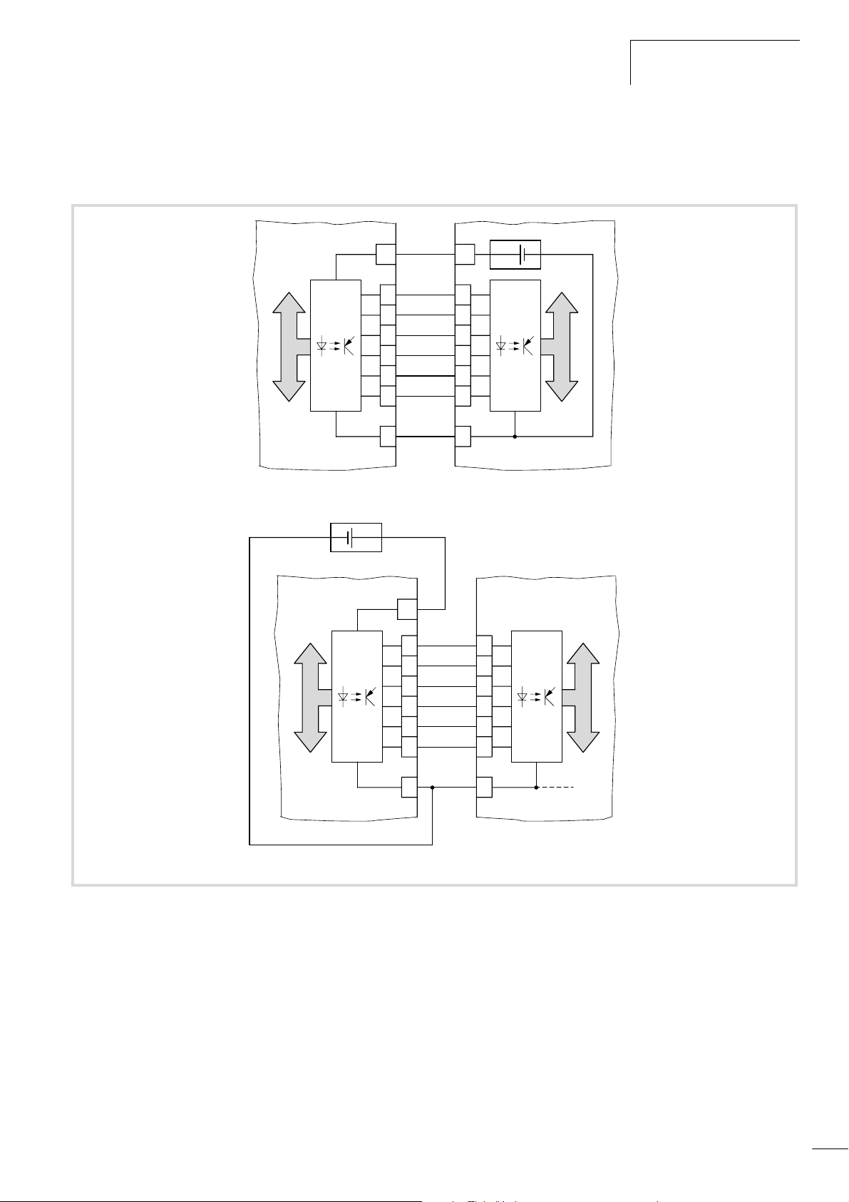
01/02 AWB8230-1413GB
efesotomasyon.com - Klockner Moeller - inverter
Example for the protective circuit of the digital inputs using the
internal P24 supply voltage or a separate external 24 V power
supply:
Electrical connection
+24 V
24 V
Q..
Q..
Q..
Q..
Q..
0 V
PLC
+24 V
+24 V
24 V
Q..
Q..
Q..
Q..
Q..
P24
FWQ..
+24 V
5
4
3
2
1
L
DF6
FWQ..
5
4
3
2
1
PLC
Figure 36: Triggering the digital inputs
0 V
L
DF6
43
Page 47
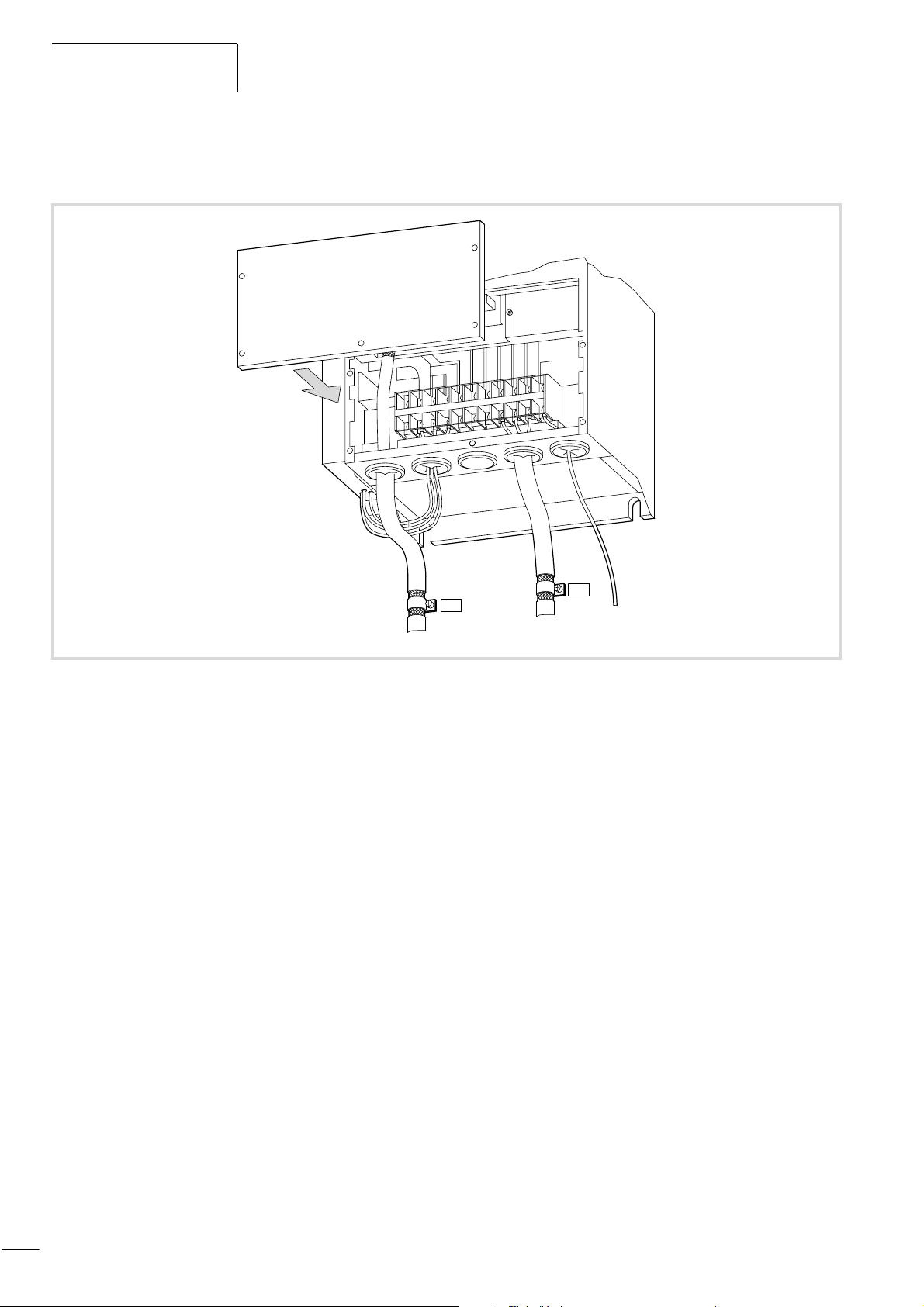
Installation
efesotomasyon.com - Klockner Moeller - inverter
Having made all cable connections, refit the terminal shroud on
the frequency inverter and tighten the screw.
01/02 AWB8230-1413GB
Figure 37: Close the terminal shroud
PES
PES
e
PE
44
Page 48
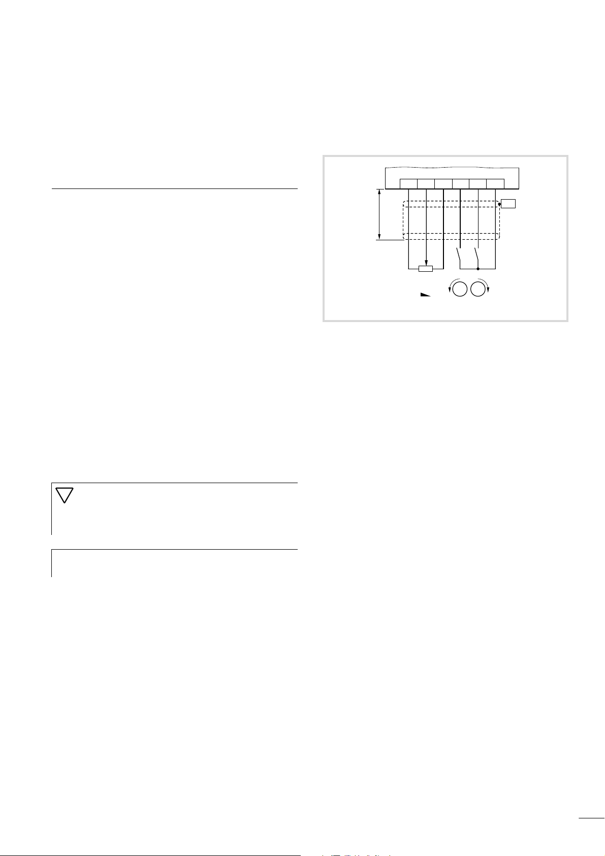
01/02 AWB8230-1413GB
efesotomasyon.com - Klockner Moeller - inverter
4 Operating the DF6
This section describes how to take the DF6 frequency inverter into
operation and what you should observe during its operation.
Initial startup
Observe the following points before you take the frequency
inverter into operation:
• Make sure that the power lines L1, L2 and L3 and the frequency
inverter outputs U, V and W are connected correctly.
• The control lines must be connected correctly.
• The earth terminal must be connected correctly.
• Only the terminals marked as earthing terminals must be
earthed.
• The frequency inverter must be installed vertically on a nonflammable surface (e.g. a metal surface).
• Remove any residue from wiring operations – such as pieces of
wire – and all tools from the vicinity of the frequency inverter.
• Make sure that the cables connected to the output terminals are
not short-circuited or connected to earth.
• Ensure that all terminal screws have been sufficiently tightened.
• Make sure that the frequency inverter and the motor are correct
for the mains voltage.
• The configured maximum frequency must match the maximum
operating frequency of the connected motor.
• Never operate the frequency inverter with opened power
section covers.
Caution!
Do not carry out h.v. tests. Built-in overvoltage filters are
fitted between the mains voltage terminals and earth,
which could be destroyed.
The control signal terminals are wired as follows.
OH
F 20 m
4K7
Figure 38: Connecting the control signal terminals (default settings)
X Switch on the supply voltage.
The POWER and Hz LEDs light up (keypad).
8L
FW P24
PES
S2
S1
M
M
FWD
REVR1
0.00 appears on the
display.
X Close switch S1 (FW = clockwise rotation).
X With potentiometer R1, you can set the frequency and therefore
the motor speed.
The motor turns clockwise and the display indicates the set
frequency.
X Open switch S1.
The motor speed is reduced to zero (display:
0.00).
Sparkover voltage and insulation resistance tests (megger
h
tests) have been carried out by the manufacturer.
X Close switch S2 (REV = anticlockwise operation).
X With potentiometer R1, you can set the frequency and therefore
the motor speed.
The motor turns anticlockwise and the display indicates the set
frequency.
X Open switch S2.
The motor speed is reduced to zero (display:
0.00).
If both switches S1 and S2 are closed, the motor will not start. If
you close both switches during operation, the motor speed is
reduced to zero.
45
Page 49
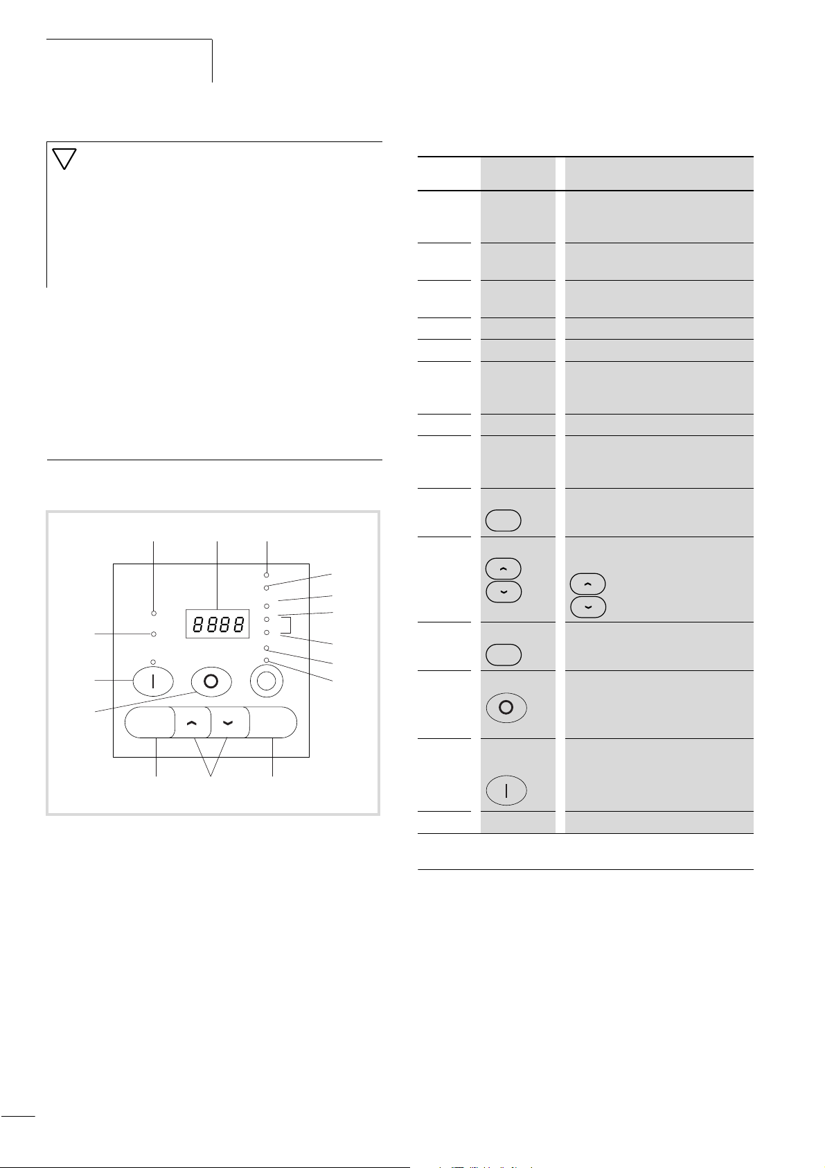
Operating the DF6
efesotomasyon.com - Klockner Moeller - inverter
01/02 AWB8230-1413GB
Caution!
During or after initial operation, check the following
points to prevent damage to the motor:
• Was the direction of rotation correct?
• Has a fault occurred during acceleration or
deceleration?
• Was the frequency displayed correctly?
• Did any unusual motor noise or vibration occur?
If a fault has occurred due to overcurrent or overvoltage, increase
the acceleration or deceleration time (a section “Acceleration
time 1”, page 105 and section “Deceleration time 1”, page 106).
By default, the ON key and the potentiometer on the keypad
(a fig. 39 and a table 8) have no assigned function.
For details about activating these devices, a section “Setting
the frequency and start signal parameters”, page 107.
Keypad
The following illustration shows the LCD keypad of the DF6.
a b c
d
e
f
g
o
RUN
PRG
POWER
ALARM
Hz
V
A
%
kW
h
n
m
PRG
MIN
MAX
ENTER
i
jkl
Table 8: Explanation of the operating and indication elements
Number Name Explanation
a RUN LED LED lights up in RUN mode if the
frequency inverter is ready for operation
or operational.
b
c
d
e
f, g
h
i
j
k
l
m
n
7-segment
display
POWER LED LED is lit when the frequency inverter
LED Alarm LED is lit when a fault has occurred.
LED Hz Indication in b: Output frequency (Hz)
LED V, A, kW Indication in b: Either output voltage
LED % Indication in b: Torque in %
Potentiometer
and LED
ENTER key This key is used for saving entered or
ENTER
Arrow keys Selecting functions, changing numeric
PRG key For selecting and exiting the
PRG
OFF key Stops the running motor and
On key and
LED
Display for frequency, motor current,
fault messages, etc.
has power.
(V) or output current (A) or a combined
current and voltage factor (kW)
Frequency setpoint setting
LED is lit when the potentiometer is
activated.
changed parameters.
values
Increase
Reduce
programming mode.
acknowledges a fault message. Active
by default, also when actuation is
through terminals.
Starts the motor in the specified
direction (not active by default).
Figure 39: Keypad view
For an explanation of each of the elements, a table 8.
46
o
PRG LED LED is lit during parameterization.
Operation with LCD keypad
The functions of the DF6 are organized in parameter groups. The
following sections describe how to set the parameter values and
how the setting menu is structured.
For a detailed description of the parameters, a section “Setting
Parameters”, page 103.
Page 50
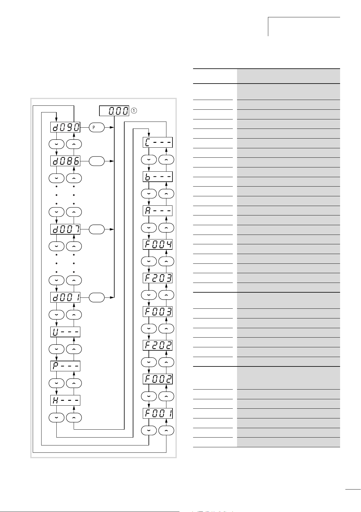
01/02 AWB8230-1413GB
efesotomasyon.com - Klockner Moeller - inverter
Operation with LCD keypad
Menu overview
The following figure shows the sequence in which the parameters
appear on the display. Table 9 provides a brief description of the
parameters.
=
PRG
PRG
PRG
PRG
Table 9: Explanation of the parameters
Display Explanation
Display
parameter
d001 Output frequency display
d002
d003
d004
d005
d006
d007
d012
d013
d014
d016
d017
d080
d081
d082
d083
d084
d085
d086
d090
Output current display
Direction of rotation display
PID feedback display
Digital inputs 1 to 5 status
Status of relay outputs K11 to K34
Scaled output frequency
Motor torque
Output voltage
Electrical input power
Running time
Mains On time
Total fault count
First (most recent) fault
Second fault
Third fault
Fourth fault
Fifth fault
Sixth fault
Warning
Basic
parameters
F001 Frequency setpoint adjustment
F002
F202
F003
F203
F004
Set acceleration time 1
Set acceleration time 1 (second parameter set)
Set deceleration time 1
Set deceleration time 1 (second parameter set)
Direction of rotation adjustment
Extended
parameter
groups
A--- Extended functions group A
b---
C---
H---
P---
U---
Extended functions, group B
Extended functions, group C
Extended functions, group H
Extended functions group P
Extended functions group U
Figure 40: DF6 keypad menu structure
a The contents of this display depends on which display parameter
(PNU d001 to d090) you have selected.
For a detailed description of the parameters, a section “Setting
Parameters”, page 103.
47
Page 51
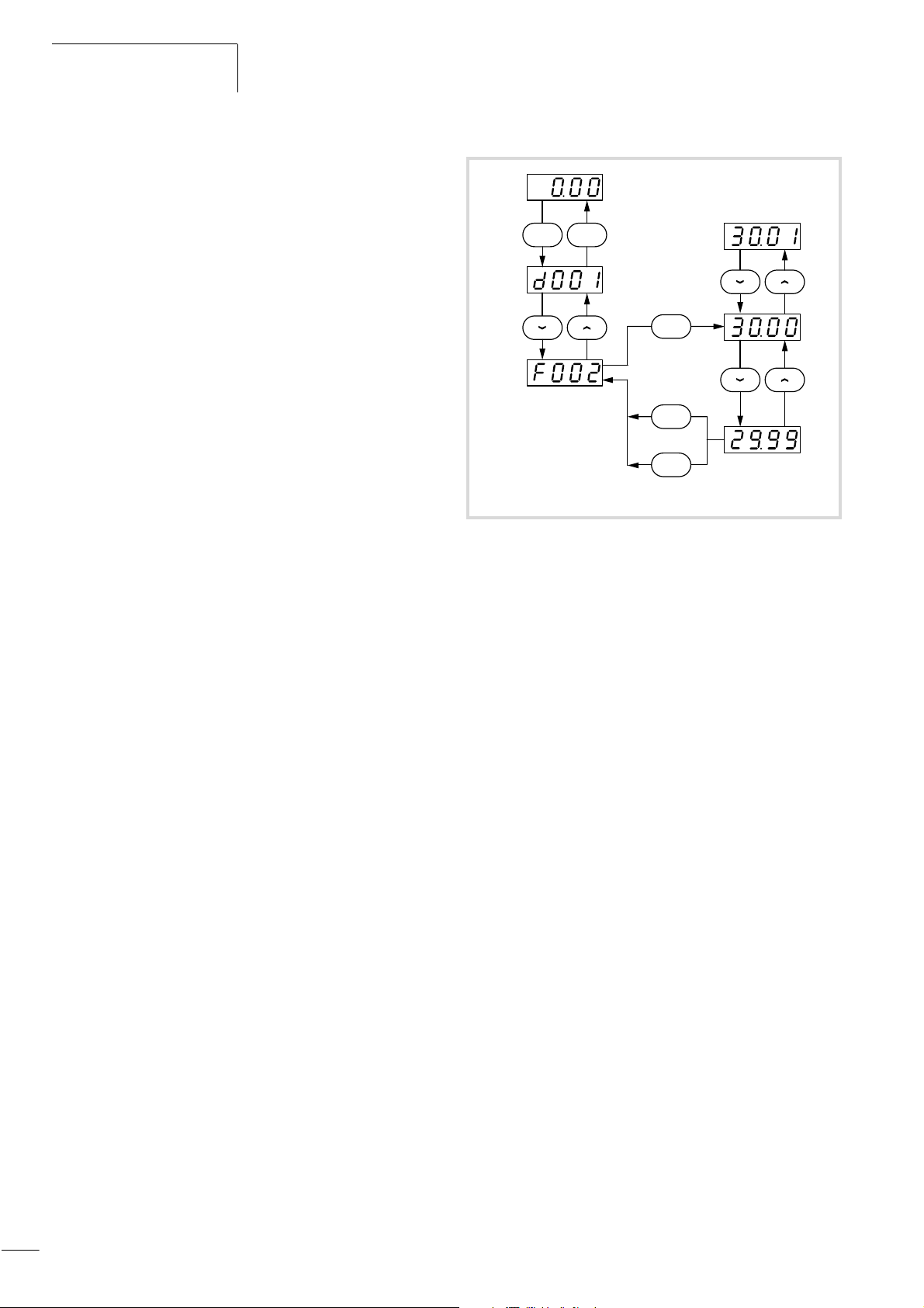
Operating the DF6
efesotomasyon.com - Klockner Moeller - inverter
01/02 AWB8230-1413GB
Changing display and Basic parameters
Press the PRG key to switch from display or RUN mode to
programming mode. The PRG lamp lights up in this mode.
You can access the individual parameters or parameter groups
with the UP and DOWN arrow keys (a fig. 40).
To access the programming mode, press the PRG key. You can
modify the parameter values with the arrow keys. Exceptions are
the display parameters PNU d001 to d090. These parameters have
no values. After you have selected a display parameter with the
arrow keys, you can return to the display mode with the PRG key.
The display then shows the selected display parameter
(a section “Setting the display parameters”, page 104).
Parameter values can be accepted with the ENTER key or rejected
with the PRG key.
To return to the display mode, press the PRG key in the display
parameter range PNU d001 to d090.
Example for changing acceleration time 1: PNU F002
The frequency inverter is in display mode and the RUN lamp is lit.
X Press the PRG key.
The frequency inverter changes to programming mode, the PRG
lamp lights up and
d001 or the most recently modified parameter
appears on the display.
a
PRG PRG
b
PRG
F02 = 29.99
ENTER
PRG
F02 = 30.00
Figure 41: Changing acceleration time 1
a Display dependent on the selected display parameter PNU d001 to
d090
b Display of the most recently changed parameter
X Press the DOWN key until F002 appears on the display.
X Press the PRG key.
The set acceleration time 1 in seconds appears on the display
(default: 30.00).
X To change the set value, use the UP and DOWN arrow keys.
There are now two possibilities:
X Accept the displayed value by pressing the ENTER key.
X Reject the displayed value by pressing the PRG key.
F002 appears on the display.
X Press the UP key until d001 appears.
X Press the PRG key.
The frequency inverter changes to the display mode and displays
the set frequency.
Changing the parameters of the extended parameter groups
The following example illustrates how to change PNU A003 of the
extended parameter group A. You can also change the parameter
values of groups B, C, H and P as described in the example. You
can change the parameter values of group U as described in
section “User-defined parameters – parameter group U”,
page 150. For a detailed description of the extended parameter
groups, a from section “Setting the frequency and start signal
parameters”, page 107.
Example for changing the base frequency: PNU A003
X Press the PRG key to change to the programming mode.
The most recently modified parameter appears on the display and
the PRG lamp lights up.
X Press the UP or DOWN key until the extended parameter group
A--- appears on the display.
X Press the PRG key.
A001 appears on the display.
X Press the UP key twice until A003 appears on the display.
X Press the PRG key.
48
The acceleration time set under PNU A003 (default value: 50.)
appears on the display.
X To change the value, use the UP and DOWN arrow keys.
Page 52
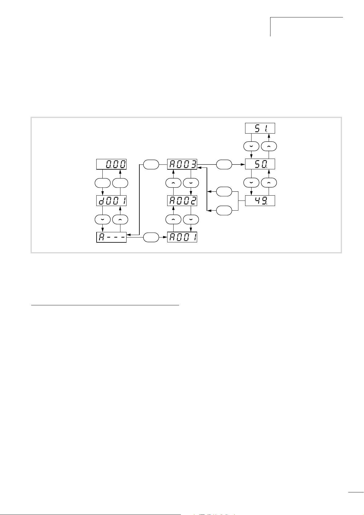
01/02 AWB8230-1413GB
efesotomasyon.com - Klockner Moeller - inverter
Display after the supply voltage is applied
There are now two possibilities:
X Accept the displayed value by pressing the ENTER key.
X Reject the displayed value by pressing the PRG key.
The display shows
X Press the PRG key.
A003.
PRG PRG
a
PRG
b
PRG
A--- appears on the display.
X Press the UP key until d001 appears.
X Press the PRG key.
The frequency inverter changes to the display mode and displays
the current frequency.
PRG
A03 = 49.
ENTER
PRG
A03 = 50.
Figure 42: Changing the base frequency (example with default setting)
a Display dependent on the selected display parameter PNU d001 to d090
b Display of the most recently changed parameter
Display after the supply voltage is applied
After the supply voltage is switched on, the last screen which was
visible before switch off will reappear (but not within the extended
parameter groups).
49
Page 53

Operating the DF6
efesotomasyon.com - Klockner Moeller - inverter
Connection examples
01/02 AWB8230-1413GB
Operation using an external potentiometer
REV
PES PES
R
(1 – 10 kO)
Figure 43: Connecting an external potentiometer
0 – 10 V
1 mA
–
+
PES
FWD
0
24 V
P24FW5FMLLOH
Configuration of the parameters
PNU Value
A001 01 Setpoint definition through control signal
A002 01
F002 10
F003 10
––
C005 01
C027 00
b081 80
Function
terminal strip
Start signal through FW(D)/REV terminals
Acceleration time in s
Deceleration time in s
FWD: Start clockwise operation on
digital input FW
REV: Start anticlockwise operation on
digital input 5
Indication of the output frequency (analog)
through the measurement device connected to
terminals L and FM
Adjustment of the analog frequency display
connected to terminals L and FM
Method of operation
You can start the frequency inverter in a clockwise direction with
terminal FW and in an anticlockwise direction with terminal 5. If
both terminals are closed simultaneously, a stop signal is issued.
With the externally connected potentiometer, the required
frequency setpoint (voltage setpoint) can be defined.
You can use the measuring instrument to display the frequency
(PNU C027 = 00) or, for example, the motor current
(PNU C027 = 01). With PNU b081, you can adjust analog output
FM to the corresponding measurement range of the measurement
device (frequency or current can be displayed).
Operation through an analog setpoint value
0
4 – 20 mA
E
Figure 44: Analog setpoint definition
REV
AT
FWD
24 V
P24FW35THCM1LOI
PESPES
Configuration of the parameters
PNU Value
A001 01 Setpoint definition through control signal terminal
A002 01
F002 10
F003 10
––
C005 01
C003 16
Function
strip
Start signal through FW(D)/REV terminals
Acceleration time in s
Deceleration time in s
FWD: Start clockwise operation on
digital input FW
REV: Start anticlockwise operation on
digital input 5
AT: Changeover to current setpoint value
(4 to 20 mA)
Method of operation
Inputs FW and 5 function exactly as described in the previous
example.
With digital input 3 (configured as AT), you can change over from
a voltage setpoint value (0 to 10 V) to a current setpoint value
(4 to 20 mA).
Instead of the wiring on terminal 3, which is fixed or realized using
a switch, you can set PNU C013 to 01. Digital input 3 is then
configured as a break contact (NC).
The circuit example also includes a motor PTC thermistor. It is
important to use a screened control cable and to lay the motor PTC
thermistor cable separately from the other motor cables. However,
the screen should be earthed at the inverter side only.
50
Page 54
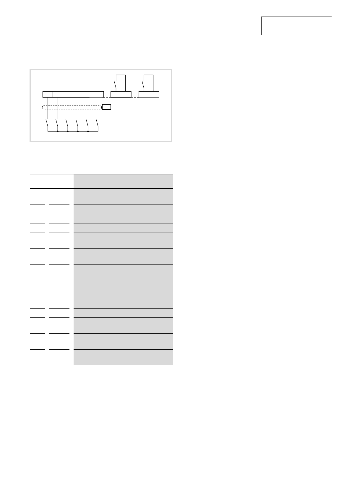
01/02 AWB8230-1413GB
efesotomasyon.com - Klockner Moeller - inverter
Connection examples
Operation with fixed frequencies
REV
FF2
FF1
RUN
FWD
24 V H
P24FW2345
K23 K24
5...30 V H, F 250 V h
PES
AT
FA1
K33 K34
Figure 45: Fixed frequency definition
Configuration of the parameters
PNU Value
A001 01 Setpoint definition through control signal
A002 01
F002 10
F003 10
––
C002 01
C003 16
C004 02
C005 03
C021 00
C022 01
A021 f
A022 f
A023 f
1
2
3
Function
terminal strip
Start signal via FWD/REV terminals
Acceleration time in s
Deceleration time in s
FWD: Start clockwise operation on
digital input FW
AT: Changeover to current setpoint value
(4 to 20 mA)
FF1: Fixed frequency input 1
FF2: Fixed frequency input 2
REV: Start anticlockwise operation on digital
input 5
RUN output signal at terminal K23-K24
FA1 output signal at terminal K33-K34
The fixed frequency to be applied when FF1 is
active and FF2 is inactive is entered here.
The fixed frequency applied when FF1 is inactive
and FF2 is active is entered here.
The fixed frequency is applied when FF1 and FF2
are both active is entered here.
Method of operation
Inputs FW and 5 function exactly as described in the first example.
With the activation of one or both fixed frequency inputs FF1 and
FF2, the current frequency setpoint applied to the motor is
replaced by the fixed frequency determined by FF1 and FF2, and
the motor brakes or accelerates according to the fixed frequency
applied. If neither of the fixed frequency inputs FF1 and FF2 is
activated, the frequency setpoint is determined through analog
inputs O (voltage setpoint value) or OI (current setpoint value). The
wiring for these terminals is not shown in this circuit example. For
the combination of the individual fixed frequency values,
a section “Fixed frequency selection (FF1 to FF4)”, page 68.
The circuit example also contains the parameter settings for one
output signal each at terminals K23-K24 and K33-K34. The output
signal type is configured with PNU C021 for relay output K23-K24
and with PNU C022 for relay output K33-K34.
51
Page 55
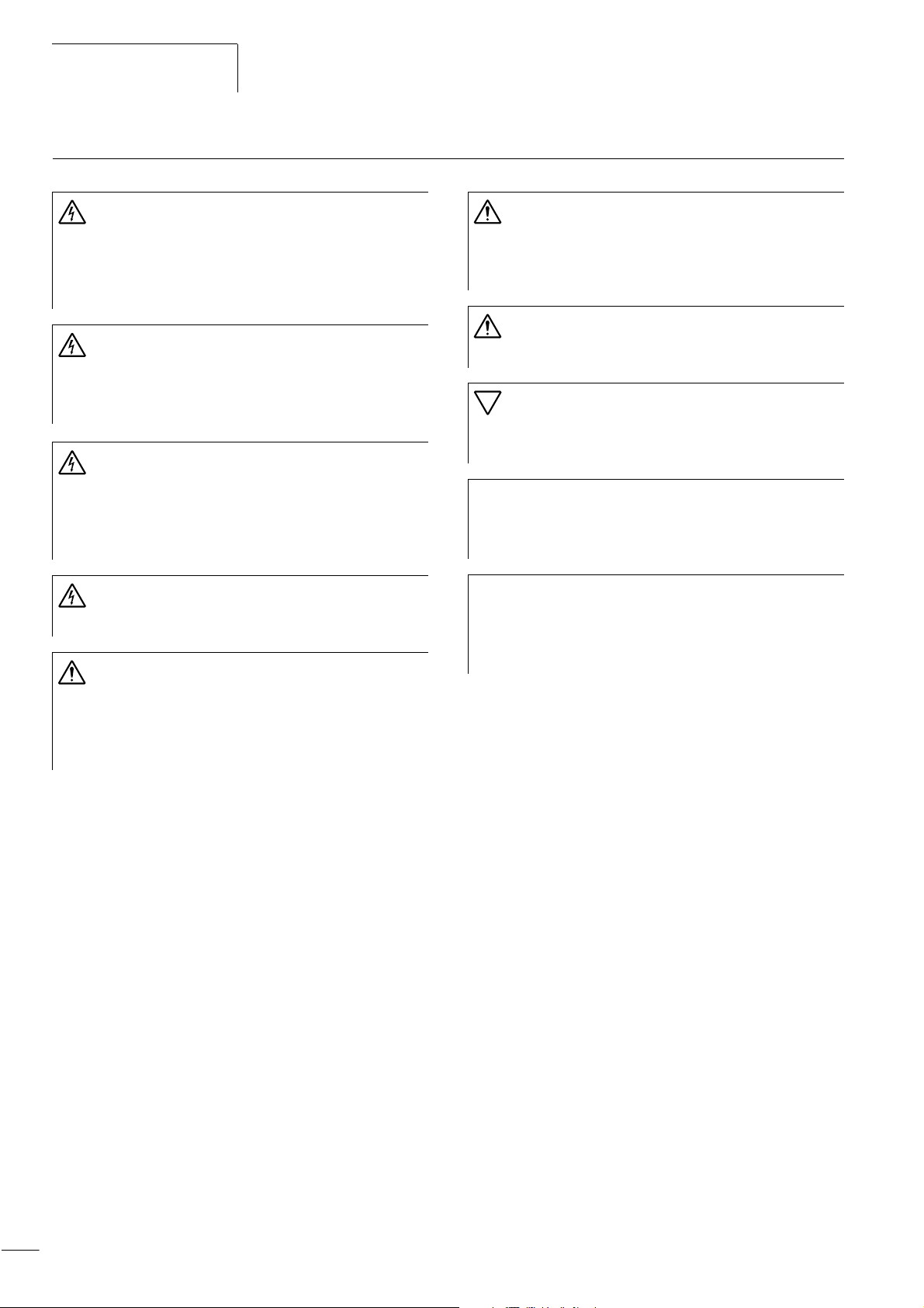
Operating the DF6
efesotomasyon.com - Klockner Moeller - inverter
Operational warnings
01/02 AWB8230-1413GB
Warning!
If the supply voltage recovers after an intermittent
failure, the motor may restart automatically if a start
signal is still present. If personnel is endangered as a
result, an external circuit must be provided which
prevents a restart after voltage recovery.
Warning!
If the frequency inverter has been configured so that the
stop signal is not issued through the OFF key on the LCD
keypad, pressing the OFF key will not switch off the
motor.
Warning!
Before carrying out maintenance and inspection work on
the frequency inverter, wait at least five minutes after the
supply voltage has been switched off. Failure to observe
this point can result in electric shock due to high
equipment voltages.
Warning!
Never pull on the cable to unplug connectors (e.g. for fan
or circuit boards).
Warning!
If a reset is issued after a malfunction, the motor will start
automatically if a start signal is also present. To avoid the
risk of serious or fatal injury to personnel, you must ensure
that the start signal is not present before acknowledging
a fault message with a reset.
Warning!
When the supply voltage for the frequency inverter is
applied while the start signal is active, the motor will
start immediately. Make sure that the start signal is not
active before the supply voltage is switched on.
Warning!
Do not connect cables or connectors during operation
when the supply voltage is switched on.
Caution!
To prevent a risk of serious or fatal injury to personnel,
never interrupt the operation of the motor by opening the
contactors installed on the primary or secondary side.
The ON key is functional only if the corresponding
h
parameters of the frequency inverter have been
configured accordingly (a section “Setting the
frequency and start signal parameters”, page 107).
Before operating motors at frequencies above the
h
standard 50 or 60 Hz, contact their manufacturer to
verify that the motors are suitable for operation at
higher frequencies. The motors could otherwise incur
damage.
52
Page 56
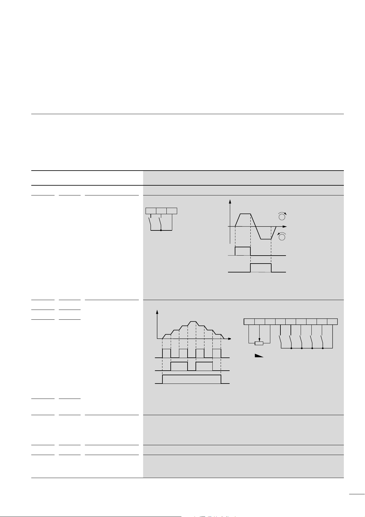
01/02 AWB8230-1413GB
efesotomasyon.com - Klockner Moeller - inverter
5 Programming the Control Signal Terminals
This section describes how to assign various functions to the
control signal terminals.
Overview
Table 10 provides an overview of the control signal terminals and
a brief description of the functions which you can assign to the
programmable digital inputs and outputs. For a detailed
description of each function, a from page 57.
Table 10: Description of the functions
1)
Name Value
Digital inputs 1 to 5 Parameterizing PNU C001 to C005
REV 01 Anticlockwise operation
Function Description
REV
(start/stop)
FWD
P24FW5
f
M
M
FWD
REV
REV input closed: motor starts up in an anticlockwise direction.
REV input open: controlled motor deceleration to stop (anticlockwise).
FW(D) and REV inputs closed simultaneously: controlled motor deceleration to stop.
FF1 02 Programmable fixed
FF2 03
frequencies 1 to 4
FF3 04
Example: Four fixed frequencies
f
f
s
f
3
f
2
f
1
FF1
FF2
FWD
f
s
fs=0 to f
max
REV
RST
FF2
FF1
FWD
P24FW345LOH8
FF4 05 For four fixed frequency stages (three programmable fixed frequencies and a setpoint value), two
2
=4).
JOG 06 Jog mode
fixed frequency inputs (3 = FF1 and 4 = FF2) are required (2
The jog mode, which is activated by switching on the JOG input, is used, for example, for setting
up a machine in manual mode. When a start signal is received, the frequency programmed under
PNU A038 is applied to the motor. Under PNU A39, you can select one of three different operating
modes for stopping the motor.
DB 07 DC braking
SET 08 Selection of the second
parameter set
When the DB input is active, DC braking can be carried out.
Switching on SET allows you to select the second parameter set for setpoint frequency, torque
boost, first and second acceleration/deceleration ramp and other functions. Parameters in the
second parameter set are identified by a leading “2”, e.g. : PNU A201 PNU A201
53
Page 57
Programming the Control
efesotomasyon.com - Klockner Moeller - inverter
Signal Terminals
1)
Name Value
2CH 09 Second time ramp Activates the second acceleration and deceleration time with PNU A092 and PNU A093
FRS 11 Controller inhibit
EXT 12 External fault
USP 13 Unattended start
CS 14 Heavy mains starting
SFT 15 Parameter protection
AT 16 Setpoint input OI
RST 18 Reset
STA 20 Pulse start (3-wire)
STP 21 Pulse stop (3-wire)
F/R 22 Direction of rotation
PID 23 Activation of PID control
PIDC 24 Resetting the integral
UP 27 Acceleration (motor
DWN 28 Deceleration (motor
UDC 29 Reset frequency (motor
OPE 31 Setpoint value via
SF1 to
SF7
OLR 39 Current limit changeover
NO no –
Non-programmable digital inputs
FW – FWD = clockwise
P24 – 24 V H for digital inputs
32 to 38 Bitwise frequency
Function Description
respectively
When FRS is switched on, the motor is immediately switched off and coasts to a stop.
(free run stop)
When the EXT input is switched on, the fault signal activates PNU E12 and the motor switches off.
The fault signal can be acknowledged, for example, with the RST input.
When the USP input is switched on, unattended start protection is active. This prevents a motor
protection
(4 to 20 mA) active
(3-wire)
component of the PID
control
potentiometer)
potentiometer)
potentiometer)
keypad
selection
operation (start/stop)
restart when the voltage recovers after a mains failure while a start signal is present.
For starting drives with extremely high starting torques
The parameter protection, which is activated by switching on the SFT input, prevents loss of the
entered parameters by inhibiting write operations to these parameters.
When the AT input is switched on, only setpoint value input OI (4 to 20 mA) is processed.
To acknowledge an error message, switch on the RST input. If a reset is initiated during operation,
the motor coasts to a stop. The RST input is a make (NO) contact; it cannot be programmed as a
break (NC) contact.
These settings enable three-wire control of these three functions.
Switching the internal PID controller on and off
When input UP is switched on, the motor accelerates (available only if you have specified the
frequency setpoint with PNU F001 or A020).
When input DWN is switched on, the motor decelerates (available only if you have specified the
frequency setpoint with PNU F001 or A020).
When the UDC input is switched on, the motor is controlled with the frequency set under
PNU A020 (available only if you have specified the frequency setpoint with PNU F001 or A020).
When this input is switched on, the frequency inverter operates with the frequency set at
PNU F001.
Motor control using a fixed frequency.
Changeover to other current limit parameters: PNU b024, b025, b026
(default setting: PNU b021, b022, b023)
No function
FW(D) input closed: motor starts up in a clockwise direction.
FW(D) input open: controlled motor deceleration to stop (clockwise).
FW(D) and REV inputs closed simultaneously: controlled motor deceleration to stop.
24 V H potential for digital inputs 1 to 5
01/02 AWB8230-1413GB
54
Page 58
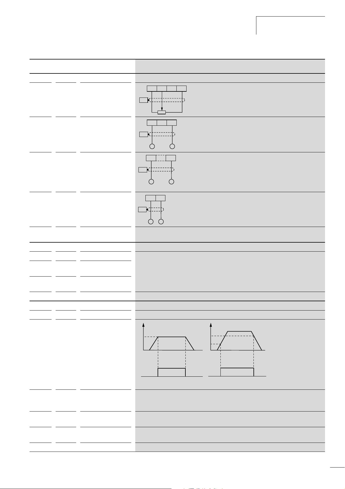
01/02 AWB8230-1413GB
efesotomasyon.com - Klockner Moeller - inverter
1)
Name Value
Function Description
Frequency setpoint input
h – 10 V setpoint voltage for
external potentiometer
PES
Overview
LOIOH
R: 1 to 10 kO
Resolution: 12-bit
O – Analog input for setpoint
frequency through
voltage signal
LOIO
PES
Input impedance: 10 kO
I F 20 mA
Resolution: 12-bit
(0 to 10 V H)
O2 – Analog input for setpoint
frequency through
voltage signal
+
PES
–
LO2
Input impedance: 10 kO
I F 20 mA
Resolution: 12-bit
(–10 to +10 V H)
–10 V...+10 V 0 V
OI – Analog input for setpoint
frequency through
current signal
(4 to 20 mA)
L – 0 V reference potential
LOI
PES
+
–
If no digital input is configured as an AT input, the setpoint values O and OI are added together.
The OI input for a setpoint value from 4 to 20 mA is used only
when the digital input configured as the AT input is closed.
Load resistance: 250 O
Resolution: 12-bit
for setpoint inputs
Analog outputs
FM – Frequency output You can assign the following variables to outputs AM, AMI and FM:
AM – Voltage output
(0 to 10 V, 8-bit)
Output frequency, motor current, torque, output voltage, input power, ramp frequency and
thermal load ratio
AMI – Current output
(4 to 20 mA, 8-bit)
L–0V
0 V reference potential for the analog output
Programmable relay outputs K23 to K34
RUN 00 RUN signal The RUN signal is output during operation of the motor.
FA1 01 Signal when frequency is
f
s
reached
f
2
f
1
fs = setpoint frequency
FA2 02 Signal when frequency is
exceeded (1)
If a digital output is configured as FA1, a signal is issued as long as the setpoint value is reached.
If a digital signal is configured as FA2, a signal is output as long as the frequencies defined under
PNU C042 and PNU C043 are exceeded.
OL 03 Signal on overload
The OL signal is output when the overload alarm threshold (adjustable under PNU C041) is
exceeded.
OD 04 Signal on PID control
The OD signal is output when the PID control deviation set under PNU C044 is exceeded.
deviation
AL 05 Signal (alarm) on fault
The AL signal is issued when a fault occurs.
FA1
FA2
55
Page 59

Programming the Control
efesotomasyon.com - Klockner Moeller - inverter
01/02 AWB8230-1413GB
Signal Terminals
1)
Name Value
Function Description
FA3 06 Frequency reached (1) The FA3 signal is issued when the output frequency lies in the frequency range defined under
PNU C042 and C043 (plus tolerance).
IP 8 Mains failure,
The IP signal is issued on intermittent mains failure.
immediate stop
UV 9 Undervoltage signal
RNT 11 Running time exceeded
ONT 12 Mains On time exceeded
THM 13 Motor thermal overload
The UV signal is output on undervoltage.
The RNT signal is output when the Running time set under PNU b034 is exceeded.
The ONT signal is output when the Mains On time set under PNU b034 is exceeded.
The THM signal is output when the motor overload warning threshold set under PNU C061 is
exceeded.
Signalling relay
2)
K11 – Signalling relay contacts During normal fault-free operation, terminals K11K14 are closed. If a malfunction occurs or the
K12
K14
supply voltage is switched off, terminals K11K12 are closed.
Maximum permissible values:
• 250 V ~; Maximum load 2.5 A (purely resistive) or 0.2 A (for a power factor of 0.4)
•30VH; Maximum load 3.0 A (purely resistive) or 0.7 A (for a power factor of 0.4)
• Minimum required values: Minimum required values: 100 V ~ at a load of 10 mA or 5 V H at a
load of 100 mA
1) To activate the function, enter this value in the corresponding parameter.
2) This output can be used as both a signal output and a normal digital output.
56
Page 60
01/02 AWB8230-1413GB
efesotomasyon.com - Klockner Moeller - inverter
Analog outputs – AM, AMI and FM
Analog outputs – AM, AMI and
FM
The analog outputs provide various physical variables, which you
can select and some of which you can adjust to meet your specific
needs. Terminals AM, AMI and FM are connected to chassis
through terminal L.
You cannot change all parameters in RUN mode. Editable
parameters in RUN mode are marked with a “j” in the “normal”
column of the table below. With PNU b031, you can set additional
parameters which are editable in RUN mode (a section
“Software protection (SFT)”, page 81). These additional
parameters are marked “j” in the “Extended” column.
Voltage output (AM)
The AM terminal provides the variables listed in the table below in
the form of a 0 to 10 V voltage signal.
X In PNU C028, specify the variable which the AM terminal is to
Adjustable in RUN mode
Normal Extended
– j
provide.
X In PNU B080, specify the gain factor and in PNU C086 the
offset.
PNU Function Adjustable in RUN mode Value Function WE
Normal Extended
b080 Gain, AM
terminal
C028 Output, AM
terminal
C086 Offset, AM
terminal
j j 0 to 255 Gain of the voltage output 180
– j 00 Output frequency: 0 Hz to end frequency PNU A004
(a section “End frequency”, page 108)
01 Output current: 0 to 200 %
04 Output voltage: 0 to 100 %
05 Inverter input power: 0 to 200 %
06 Thermal load ratio: 0 to 100 %
07 Ramp frequency: 0 Hz to end frequency PNU A004
(a section “End frequency”, page 108)
j j 0 to 10 V Voltage increase 0.0
00
57
Page 61
Programming the Control
efesotomasyon.com - Klockner Moeller - inverter
Signal Terminals
01/02 AWB8230-1413GB
Current output (AMI)
The AMI terminal provides the variables listed in the table below
in the form of a 4 to 20 mA current signal.
X In PNU C029, specify the variable which the AMI terminal is to
provide.
X In PNU C087, specify the gain factor and in PNU C088 the
offset.
PNU Function Adjustable in RUN mode Value Function WE
Normal Extended
C029 Output, AMI
terminal
C087 Gain, AMI
terminal
C088 Offset, AMI
terminal
– j 00 Output frequency: 0 Hz to end frequency PNU A004
01 Output current: 0 to 200 %
04 Output voltage: 0 to 100 %
05 Inverter input power: 0 to 200 %
06 Thermal load ratio: 0 to 100 %
07 Ramp frequency: 0 Hz to end frequency PNU A004
j j 0 to 255 Current output gain 80
j j 0 to 20 mA Current increase 0.0
Frequency output (FM)
The FM terminal provides the variables listed in the table below in
the form of a pulse-width modulated (PWM) signal (a fig. 46).
An exception is the output frequency to which the value “03” is
assigned which is output as a frequency modulated (FM) signal
(a fig. 48).
X In PNU C027, specify the variable which the FM terminal is to
provide.
X In PNU B081, specify the gain factor.
00
(a section “End frequency”, page 108)
(a section “End frequency”, page 108)
PNU Function Adjustable in RUN mode Value Function WE
Normal Extended
C027 Output, FM
terminal
b081 Gain, FM
terminal
58
– j 00 Output frequency: PWM signal 00
01 Output current
03 Output frequency: FM signal
04 Output voltage
05 Inverter input power
06 Thermal load ratio
07 Ramp frequency
j j 0 to 255 Gain of the frequency output 60
Page 62
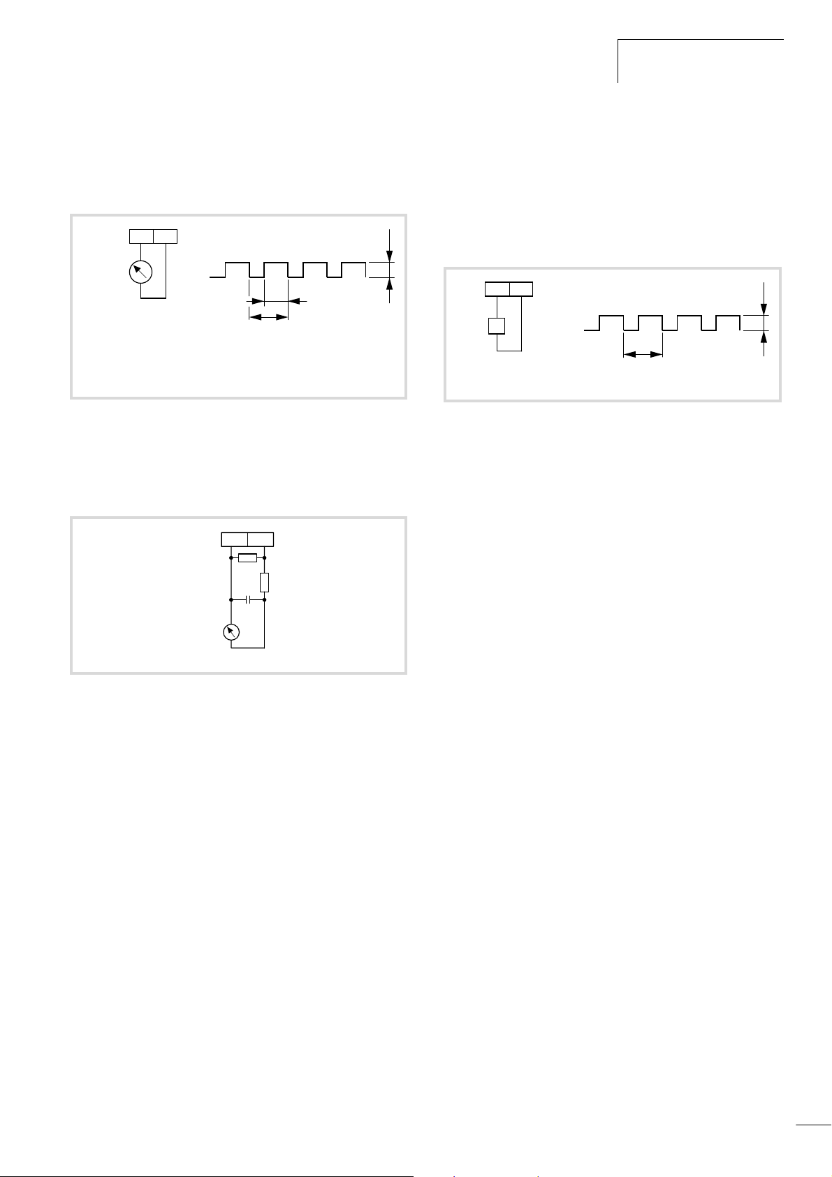
01/02 AWB8230-1413GB
efesotomasyon.com - Klockner Moeller - inverter
Analog outputs – AM, AMI and
FM
PWM signal
The output signal is a square wave with a constant period of
oscillation. Its pulse width is proportional to the current frequency
value (0 to 10 V correspond to 0 Hz to the end frequency).
FML
–
0 – 10 V
1 mA
+
Analog measuring
instrument
0 to 10 V
1mA
t/T = variable
T = 4 ms (constant)
t
T
Figure 46: Connection of analog measuring instrument
10 V
If, for example, a higher level of smoothing of the PWM signal is
required for a motor current display, an external low-pass filter
circuit is required.
FML
FM signal
The frequency of this signal (PNU C027 = 00) changes
proportionally to the output frequency. The pulse duty factor
remains constant at about 50 %. The output frequency at the FM
terminal is ten times that of the DF6 frequency inverter’s maximum
output frequency, i.e. up to 4 kHz. This signal does not have to be
matched; its accuracy is monitored digitally.
FML
–
f
+
Digital frequency meter T = 1/(output frequency x factor)
T
Figure 48: Digital frequency meter connection
10 V
33 kO
+
1 mF
–
0 – 10 V
1 mA
+
Figure 47: Example of a low-pass circuit
82 kO
59
Page 63
Programming the Control
efesotomasyon.com - Klockner Moeller - inverter
Signal Terminals
Analog inputs terminals O, O2 and OI
01/02 AWB8230-1413GB
You can specify the setpoint frequency through three analog
inputs:
• Terminal O: 0 to 10 V
• Terminal O2: –10 V to +10 V
• Terminal OI: 4 to 20 mA
Frequency setpoint definition
By default, the frequency setpoint definition is made through the
voltage input (0 to 10 V). Alternatively, you can enter the setpoint
value through one of the other analog inputs or a combination of
two analog inputs. To do this, configure a digital input with the AT
function (a section “Analog input changeover (AT)”, page 72).
The reference potential for the analog inputs is terminal L.
PNU Name Adjustable in RUN mode Value Function WE
Normal Extended
A005 AT selection – – 00 Changing over from O to OI 00
01 Changing over from O to O2
A006 O2 selection
– – 00 O2 signal only 00
01 Sum of signals at O2 and O or OI without direction reversal
02 Sum of signals at O2 and O or OI with direction reversal
The two inputs are specified under PNU A005 and A006.
The table below shows how you can link analog inputs O, O2 and
OI with PNU A005 and A006.
Main frequency
setpoint value
input
O2 signal sum Reversal of
direction with
O2
AT input
configured
A006 A005 Input AT
OYes YesYes 02 00 Off
01
No
No No
Add O + OI Yes Yes
No
O2 No Yes
No
OI Yes Yes
Yes No
No No
Yes 01 00 Off
01
Yes 00 00 Off
00 01
No 00 – –
02
01
Yes 02 01 On
00
01
Yes 02 00 On
01
00
60
Page 64
01/02 AWB8230-1413GB
efesotomasyon.com - Klockner Moeller - inverter
Analog inputs
terminals O, O2 and OI
Matching of terminals O, O2 and OI
With PNU C081 to C083 and PNU C121 to C123, you can adapt
the analog setpoint signals at terminals O, O2 and OI to your
Caution!
These parameters are not reset to their default values
during initialization.
requirements:
• Matching of terminal O 0 to +10 V
– Matching of setpoint signal: PNU C081
– Zero point matching: PNU C121
• Terminal O2, –10 V to +10 V
– Matching of setpoint signal: PNU C083
– Zero point matching: PNU C123
• Terminal OI: 4 to 20 mA
– Matching of setpoint signal: PNU C082
– Zero point matching: PNU C122
PNU Name Adjustable in RUN mode Value Function WE
Normal Extended
C081 Matching of
terminal O
C082 Matching of
terminal OI
C083 Matching of
terminal O2
C121 Zero-point
matching,
terminal O
C122 Zero-point
matching,
terminal OI
C123 Zero-point
matching,
terminal O2
j j 0 to 65 530 Here, you can match the setpoint signal (0 to +10 V)
supplied at analog input O with reference to the output
frequency.
Here, you can match the setpoint signal (4 to 20 mA)
supplied at analog input OI with reference to the output
frequency.
Here, you can match the setpoint signal supplied at analog
input O2 (–10 V to +10 V) with reference to the output
frequency.
0 to 6553
(65530)
Here, you can match the setpoint signal (0 to +10 V)
supplied at analog input O with reference to the zero point.
Here, you can match the setpoint signal (4 to 20 mA)
supplied at analog input OI with reference to the zero
point.
Here, you can match the setpoint signal (–10 V to +10 V)
supplied at analog input O2 with reference to the zero
point.
Depending on
DF6
61
Page 65
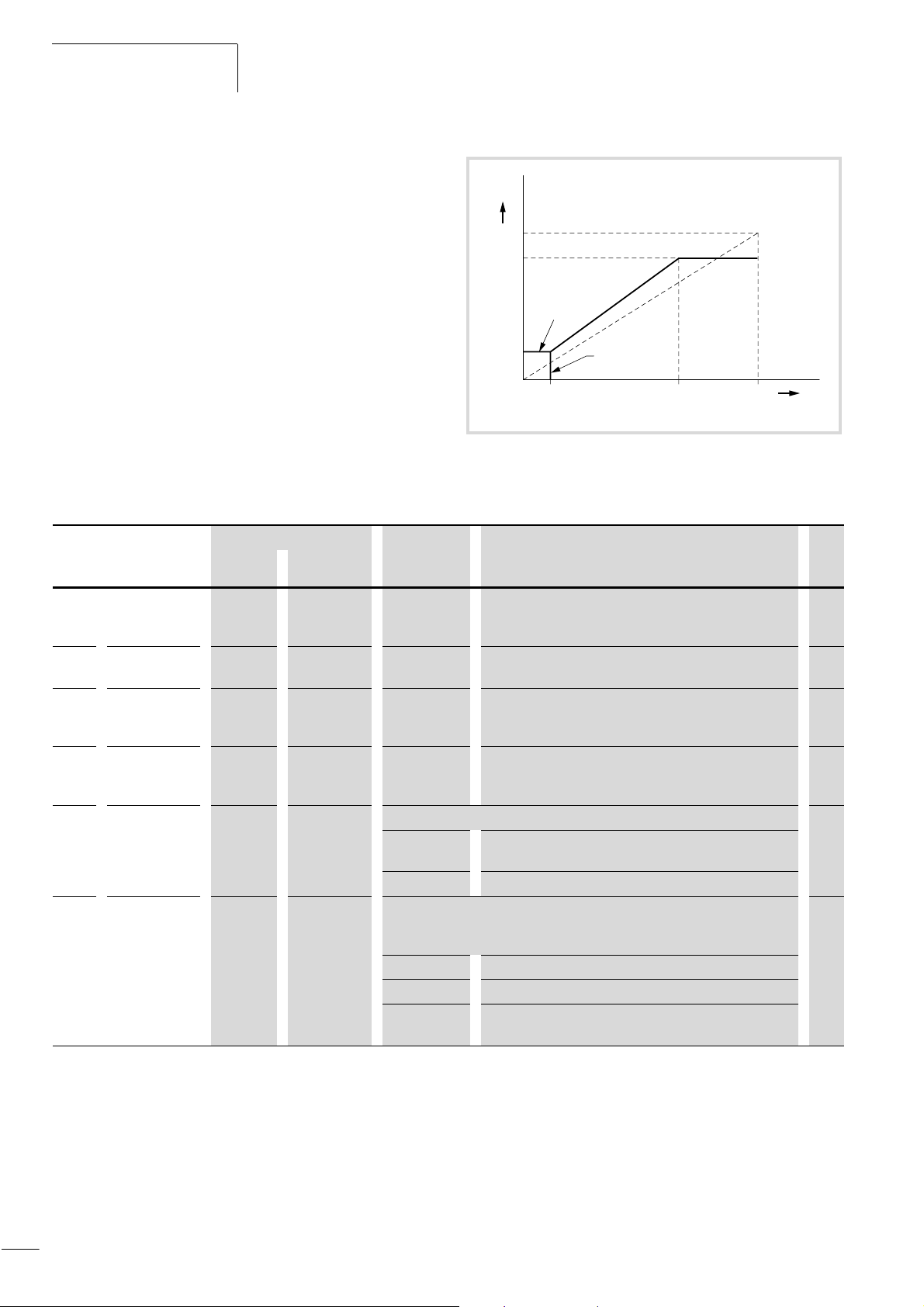
Programming the Control
efesotomasyon.com - Klockner Moeller - inverter
Signal Terminals
01/02 AWB8230-1413GB
Analog setpoint value matching
The external setpoint signal can be specifically matched with
f
[Hz]
parameters PNU A011 to A016 and A101 to A114, which are
described below. A configurable voltage or current setpoint range
can be assigned to a configurable frequency range.
PNU A004
PNU A012
Furthermore, analog setpoint signal filtering can be adjusted using
PNU A016.
Matching analog input O
figure 49 shows how to match the analog signal (0 to +10 V).
With PNU A013 and A014, you specify the active voltage range. In
PNU A011, you can set the starting point, and in PNU A012 the
end point for the output frequency. If the line does not start at the
PNU A011
PNU A015 = 00
PNU A015 = 01
PNU A013 PNU A014
0 V
0 % 100 %
10 V
U
O-L
origin, (PNU A011 and A013 > 0), specify the starting frequency
with PNU A015. As long as the input signal is smaller than the
value set in PNU A013, either 0 Hz (for PNU A015 = 00) or
Figure 49: Setpoint matching, terminals O–L
PNU A011 (for PNU A015 = 01) is output.
PNU Name Adjustable in RUN mode Value Function WE
Normal Extended
A011 Starting
frequency,
input O
A012 End frequency,
input O
A013 Minimum
setpoint
voltage, input O
A014 Maximum
setpoint
voltage, input O
A015 Condition for
starting
frequency for
analog input O
A016 Analog input
filter time
constant
– j 0.00 to 400 Hz Here, you define the starting frequency for the minimum
setpoint voltage (PNU A013).
– j 0.00 to 400 Hz Here, you define the end frequency for the maximum
setpoint voltage (PNU A014).
– j 0 to 100 % Minimum setpoint voltage as a percentage of the greatest
possible voltage (+10 V).
– j 0 to 100 % Maximum setpoint voltage as a percentage of the greatest
possible voltage (+10 V).
– j Determines the behaviour at setpoint values below the minimum setpoint value. 01
00 The frequency defined under PNU A011 is applied to the
motor.
01 A frequency of 0 Hz is applied to the motor.
– j Averaging for attenuating any superimposed interference frequencies at analog
inputs O, O2 or OI. The value between 1 and 30 specifies the number of values
to be averaged.
1 Low filtering effect, fast response to setpoint value changes
....
30 Strong filtering effect, delayed response to setpoint value
changes
0.00
0.00
0
100
8
62
Page 66
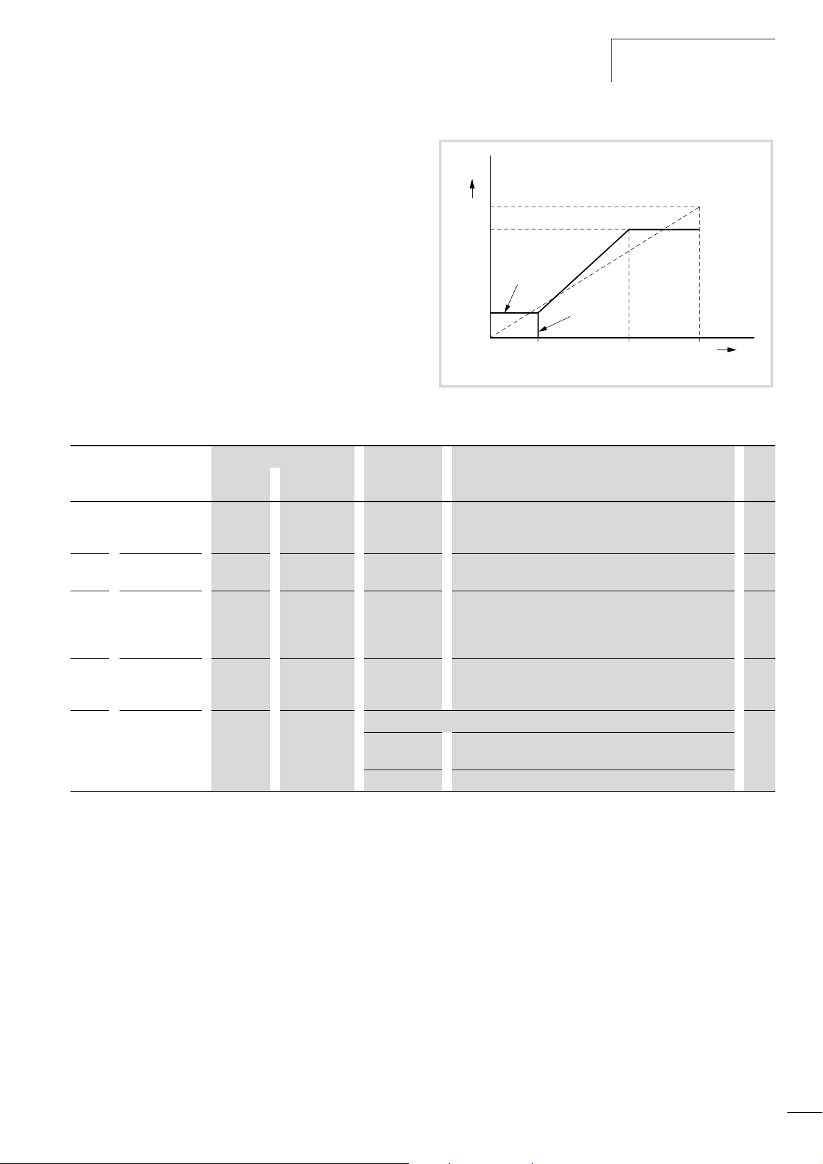
01/02 AWB8230-1413GB
efesotomasyon.com - Klockner Moeller - inverter
Analog inputs
terminals O, O2 and OI
Matching analog input OI
figure 50 shows the matching possibilities for the 4 to 20 mA
setpoint current. With PNU A103 and A104, you specify the active
current range. In PNU A101, you can set the starting point, and in
PNU A102 the end point for the output frequency. If the line does
not start at the origin, (PNU A101 and A103 > 0), the starting
f
[Hz]
PNU A004
PNU A102
frequency with PNU A105. As long as the input signal is smaller
than the value entered under PNU A103, either 0 Hz (for
PNU A105 = 00) or PNU A101 (for PNU A105 = 01) is output.
PNU A101
Figure 50: Setpoint current, terminals OI-L
PNU Name Adjustable in RUN mode Value Function WE
Normal Extended
A101 Starting
frequency,
input OI
A102 End frequency,
input OI
A103 Minimum
current
setpoint,
input OI
A104 Maximum
setpoint
current, input OI
A105 Condition for
starting
frequency for
analog input OI
– j 0.00 to 400 Hz Here, you define the starting frequency for the minimum
setpoint current (PNU A103).
– j 0.00 to 400 Hz Here, you define the end frequency for the maximum
setpoint current (PNU A104).
– j 0 to 100 % Minimum setpoint value as a percentage of the highest
possible current (20 mA).
– j 0 to 100 % Minimum setpoint value as a percentage of the highest
possible setpoint current (20 mA).
– j Determines the behaviour at setpoint values below the minimum setpoint value. 01
00 The frequency defined under PNU A101 is applied to the
motor.
01 A frequency of 0 Hz is applied to the motor.
PNU A105 = 0
PNU A105 = 1
4 mA
0 % 100 %
PNU A103 PNU A104
20 mA
I
OI-L
0.00
0.00
20
100
63
Page 67
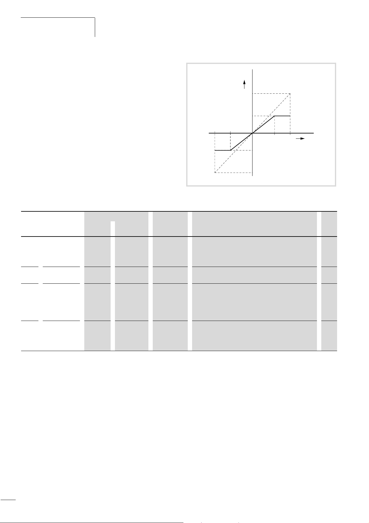
Programming the Control
efesotomasyon.com - Klockner Moeller - inverter
Signal Terminals
01/02 AWB8230-1413GB
Matching analog input O2
figure 51 shows the matching possibilities for setpoint voltages
from –10 to +10 V.
The associated operating range is specified with PNU A113 and
f
[Hz]
PNU A004
A114 for the voltage, and with PNU A111 and A112 for the
frequency. At a zero value, the setpoint polarity, and therefore the
direction of rotation, are reversed. If the input voltage falls below
the value specified in PNU A113, the DF6 frequency inverter
outputs the frequency specified in PNU A111; if the input voltage
–10 V
–100 %
is higher than PNU A114, the DF6 outputs the frequency specified
in PNU A112.
Figure 51: Setpoint matching, terminals O2L
PNU Name Adjustable in RUN mode Value Function WE
Normal Extended
A111 End frequency
on direction
reversal,
input O2
A112 End frequency,
input O2
A113 Maximum
setpoint voltage
at direction
reversal,
input OI
A114 Maximum
setpoint
voltage,
input OI
– j –400 to
400 Hz
– j –400 to
400 Hz
– j –100 to
+100 %
– j –100 to
+100 %
Here, the end frequency that corresponds to the voltage
setpoint value specified under PNU A113 is set.
Here, the end frequency that corresponds to the voltage
setpoint value specified under PNU A114.
The minimum setpoint value entered here is a percentage
of the highest possible setpoint voltage (–10 V to +10 V).
The maximum setpoint value entered here is a percentage
of the highest possible setpoint voltage (–10 V to +10 V).
PNU A113
PNU A112
PNU A111
PNU A004
PNU A1140
+10 V
+100 %
U
O2-L
0.00
0.00
–100
100
64
Page 68
01/02 AWB8230-1413GB
efesotomasyon.com - Klockner Moeller - inverter
Programmable digital inputs 1 to 5
Programmable digital inputs
1to5
Various functions can be assigned to terminals 1 to 5. Depending
on your requirements, you can configure these terminals as
follows:
• anticlockwise start signal (REV),
• selection inputs for various fixed frequencies (FF1 to FF4),
• reset input (RST),
•etc.
The terminal functions for programmable digital inputs 1 to 5 are
configured with PNU C001 to C005, i.e. with PNU C001, you
specify the function of digital input 1, with PNU C002 the function
of digital input 2, etc. Note, however, that you cannot assign the
same function to two inputs at the same time.
Programmable digital inputs 1 to 5 are configured by default as
make contacts. If, therefore, you want to activate the function of
an input terminal, you must close the corresponding input (i.e.
connect the input terminal to terminal P24). Conversely, to
deactivate the input terminal, the input must be opened.
Caution!
If an EEPROM error occurs, (fault message E08), all
parameters must be checked to ensure that they are
correct (especially the RST input).
Table 11: Digital inputs 1 to 5
PNU Terminal Adjustable in
RUN mode
Normal Exten-
ded
C001 1 – j a table 12 18
C002 2
C003 3
C004 4
C005 5
Value WE
16
03
02
01
For a detailed description of the input functions, see the pages
listed in table 12.
Table 12: Functions of the digital inputs
Value Function Description a page
01 REV Start/stop anticlockwise 67
02 FF1
03 FF2
04 FF3
05 FF4
06 JOG
07 DB
08 SET
09 2CH
11 FRS
12 EXT
13 USP
14 CS
15 SFT
16 AT
18 RST
20 STA
21 STP
22 F/R
23 PID
24 PIDC
27 UP
28 DWN
29 UDC
32 SF1
33 SF2
34 SF3
35 SF4
36 SF5
37 SF6
38 SF7
39 OLR
no NO
First fixed frequency input 68
Second fixed frequency input
Third fixed frequency input
Fourth fixed frequency input
Jog mode 78
DC brake 85
Selection of the second
parameter set
Second acceleration and
deceleration time
Motor shutdown and free run
stop (coasting)
External fault 75
Unattended start protection 76
Heavy starting duty 88
Parameter protection 81
Setpoint definition through
current signal
Reset 77
Pulse start (3-wire) 91
Pulse stop (3-wire) 91
Direction of rotation (3-wire) 91
Activation of PID control 92
Reset integral component 92
Acceleration
(motor potentiometer)
Deceleration
(motor potentiometer)
Reset frequency
(motor potentiometer)
Bitwise fixed frequency
selection
Current limit switch over 87
No function –
84
73
74
72
82
82
82
70
65
Page 69
Programming the Control
efesotomasyon.com - Klockner Moeller - inverter
Signal Terminals
You can optionally configure the digital inputs as break (NC)
contacts. To do this, enter 01 under PNU C011 to C015
(corresponding to digital inputs 1 to 5).
An exception applies to the RST input (reset), which can only be
operated as a make (NO) contact. FW is configured as a make (NO)
contact under PNU C019.
Caution!
If you configure digital FW or REV inputs as break contacts
(the default setting is as a make contact), the motor starts
immediately. They should not be reconfigured as break
contacts unless this is unavoidable.
Table 13: Configuring digital inputs as break contacts
PNU Terminal Value Adjustable in RUN mode Function WE
Normal Extended
01/02 AWB8230-1413GB
C011 1 00 or 01 – j 00: Make
C012 2
C013 3
C014 4
C015 5
C019 FW
contact
01: Break
contact
00
66
Page 70
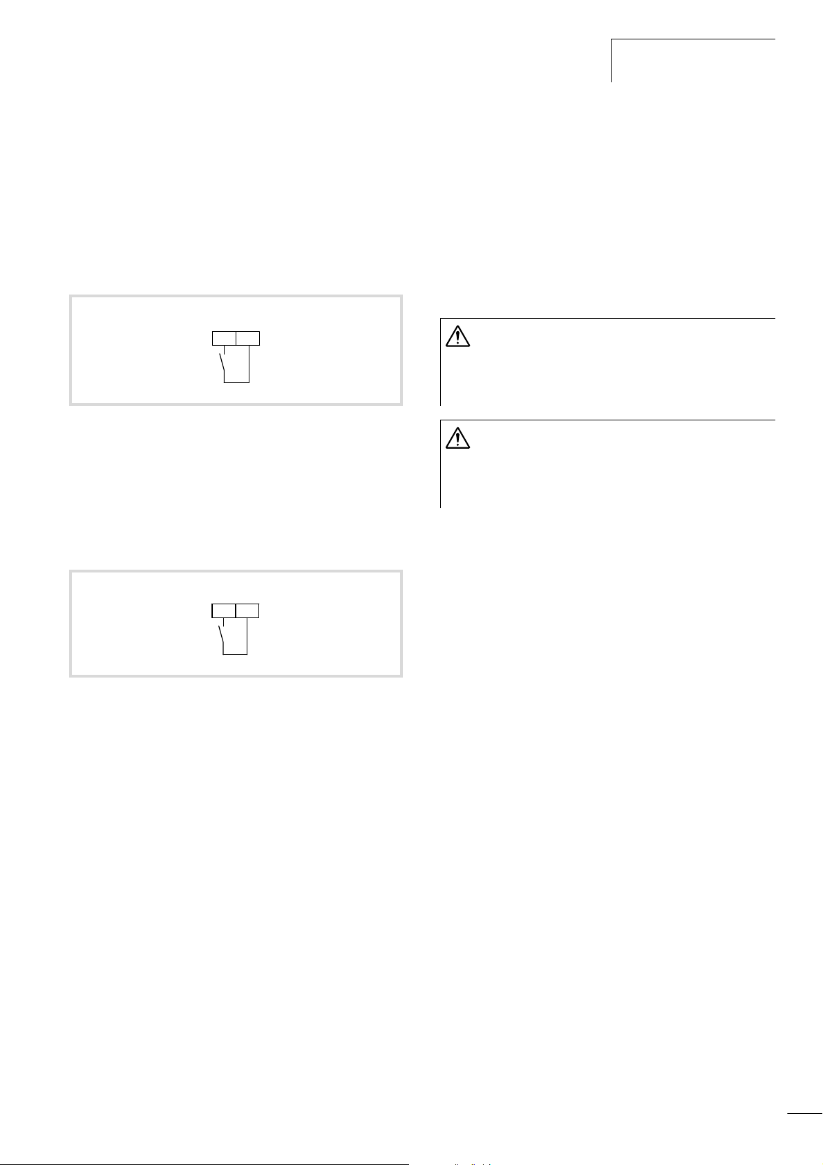
01/02 AWB8230-1413GB
efesotomasyon.com - Klockner Moeller - inverter
Programmable digital inputs
1to5
Start/stop
Clockwise operation (FW
When a digital input configured as FW is activated, the motor
starts to run in a clockwise direction. When the input is
deactivated, the motor is decelerated to a stop under frequency
inverter control.
If you activate the FW and the REV input at the same time, the
motor is decelerated under frequency inverter control.
FWD
P24FW
Figure 52: Digital input FW configured as FWD (start/stop clockwise
operation)
Anticlockwise operation (REV)
When a digital input configured as REV is activated, the motor
starts to run in an anticlockwise direction. When the input is
deactivated, the motor is decelerated to a stop under frequency
inverter control.
REV
P245
Issue start signal
By default, the start signal is issued through the inputs configured
as FW or REV. If the start signal will be issued through the ON key
on the keypad, set PNU A002 to 01 (start signal through FW/REV
input) (a section “Start signal”, page 108).
X Program one of the digital inputs 1 to 5 as REV by entering the
value 01 under the corresponding PNU (C001 to C005).
By default, REV is assigned to digital input 5.
Warning!
If the frequency inverter supply voltage is applied when
the start signal is activated, the motor will start
immediately. Make sure that the start signal is not active
before the supply voltage is switched on.
Warning!
When the FW/REV input is open (inactive state when FW/
REV is configured as a make contact), and is then
configured as break contact, the motor will start
immediately after configuration.
Figure 53: Digital input 5 configured as REV (start/stop anticlockwise
operation)
67
Page 71
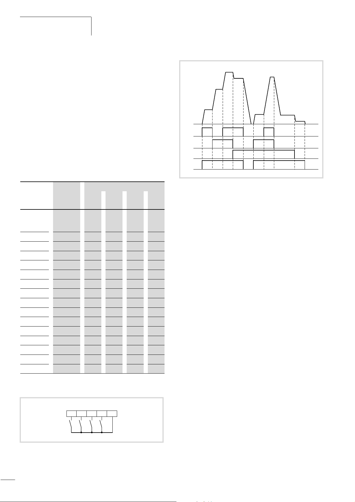
Programming the Control
efesotomasyon.com - Klockner Moeller - inverter
Signal Terminals
01/02 AWB8230-1413GB
Fixed frequency selection (FF1 to FF4)
With the digital inputs configured as FF1 to FF4, you can select up
to 16 user-definable fixed frequencies (including frequency
setpoints), depending on which of the inputs is active or inactive
(a table 14). It is not necessary to use all the fixed frequency
selection inputs at the same time. Using only three inputs, for
example, allows you to choose between eight fixed frequencies;
with two fixed frequency selection inputs, four fixed frequencies
are available for selection.
The fixed frequencies have a higher priority than all other setpoint
values and can be accessed at any time through inputs FF1 to FF4
without needing to be enabled separately. Jog mode, to which the
highest priority is assigned, is the only operation with a higher
priority than the fixed frequencies.
Table 14: Fixed frequencies
Fixed
frequency
stage
0 = f
s
f
f
2
f
f
4
f
5
f
6
f
7
f
8
f
9
f
10
f
11
f
12
f
13
f
14
f
15
0 = input deactivated
1 = input activated
PNU Input
FF4 FF3 FF2 FF1
Frequency
0 0 0 0
setpoint
value
A021 0 0 0 1
A022 0 0 1 0
A023 0 0 1 1
A024 0 1 0 0
A025 0 1 0 1
A026 0 1 1 0
A027 0 1 1 1
A028 1 0 0 0
A029 1 0 0 1
A030 1 0 1 0
A031 1 0 1 1
A032 1 1 0 0
A033 1 1 0 1
A034 1 1 1 0
A035 1 1 1 1
FF4
FF3
FF2
FF1
4
P24123
f
FF1
FF2
FF3
FWD
3
f
5
f
2
f
1
f
7
f
6
f
4
f
s
Figure 55: Function chart for FF1 to FF3 (fixed frequency control)
X Under PNU A019, enter the value 00 to activate the fixed
frequencies FF1 to FF4.
X Program one or more of the digital inputs 1 to 5 as FF1 to FF4,
by entering the values 02 (FF1) to 05 (FF4) under the
corresponding PNU (C001 to C005).
By default, FF1 is preassigned to digital input 4 and FF2 to digital
input 3.
The fixed frequencies can be programmed in two ways:
• by entering the fixed frequencies under PNU A021 to A035,
• by entering the fixed frequencies under PNU F001.
With PNU F001, you can change parameters even when the
parameter protection has been set (a page 81).
Entering the fixed frequencies under PNU A021 to A035
X Go to PNU A021 and press the PRG key.
X Use the arrow keys to enter the fixed frequency and confirm
with the ENTER key.
X Enter the remaining fixed frequencies by repeating these steps
for PNU A022 to A035.
Entering the fixed frequencies in PNU F001
Before you can enter the frequencies under PNU F001, you must
set the value 02 in PNU A001.
X To select a fixed frequency stage, activate the digital inputs as
listed in table 14.
X Go to PNU F001.
The current frequency appears on the display.
Figure 54: Digital inputs 1 to 4 configured as FF1 to FF4 (fixed
frequency)
68
X Use the arrow keys to enter the fixed frequency and confirm
with the ENTER key.
The entered value is saved under the parameter which you have
selected with the digital inputs (a table 14).
X Repeat these steps for your additional fixed frequencies.
Page 72
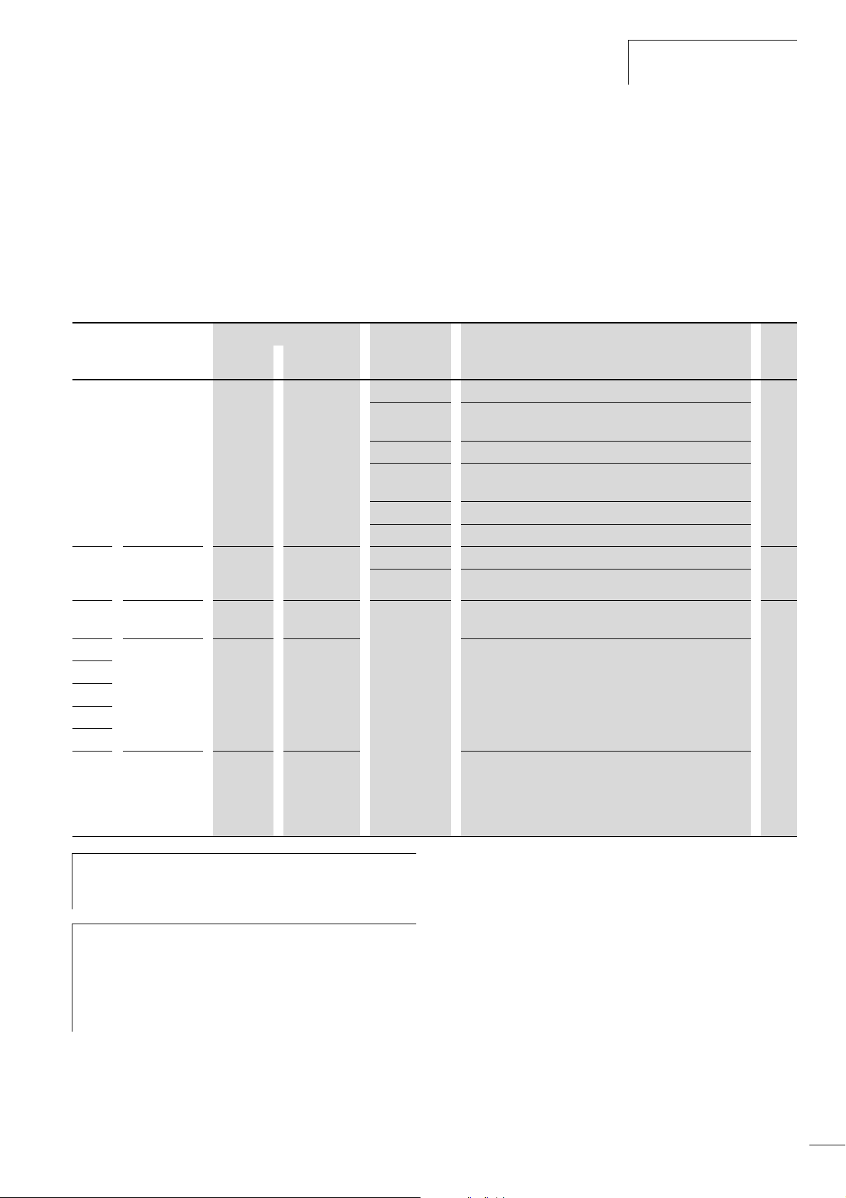
01/02 AWB8230-1413GB
efesotomasyon.com - Klockner Moeller - inverter
Start/stop
Specifying frequency setpoints
The setpoint frequency can be assigned in one of three ways,
depending on PNU A001:
• through the installed potentiometer on the keypad,
PNU A001 = 00;
• through analog input O (0 to 10 V), O2 (10 V to +10 V) or OI
(4 to 20 mA), PNU A001 = 01 (default);
• through PNU F001 or PNU A020, PNU A001 = 02.
Table 15: Fixed frequency parameters
PNU Name
A001 Defined
frequency
setpoint
A019 Selection of
fixed frequency
actuation
A020
A220
A021 Fixed
A022
A023
...
A035
F001 Input/display
Frequency
setpoint value
frequency
frequency
value
Adjustable in RUN mode Value Function WE
Normal Extended
– – 00 Definition with the potentiometer on the keypad 01
01 Definition through analog input O (0 to 10 V),
02 Definition through PNU F001 and/or PNU A020
03 Definition through RS 485 serial interface RP,
04 Definition through optional card at slot 1
05 Definition through optional card at slot 2
– – 00 Binary (FF1 to FF4) 00
01 Bitwise (SF1 to SF7)
j j 0 to 400 Hz You can enter a frequency setpoint value. You must set
j j You can assign a frequency to each of the 15 fixed frequency
j j Indication of the current frequency setpoint value or the
Selecting fixed frequencies
X Select the defined fixed frequencies by activating the respective
digital inputs (a table 14).
OI (4 to 20 mA) or O2 (–10 V to +10 V H)
2 x SN and SP
0.0
PNU A001 to 02 for this purpose.
parameters from PNU A021 to A035.
current fixed frequency.
Modified values are saved with the ENTER key according to
the selection of the digital inputs configured as FF1 to FF4.
Resolution g0.1 Hz
If one or more of the fixed frequencies exceeds 50 Hz, you
h
must first increase the end frequency with PNU A004
(a section “End frequency”, page 108).
Fixed frequency stage 0 (none of the inputs FF1 to FF4 are
h
activated) corresponds to the frequency setpoint value.
Depending on the value entered in PNU A001, this can be
defined with the installed potentiometer, the setpoint
value inputs O and/or OI or through PNU F001 and
PNU A020.
69
Page 73
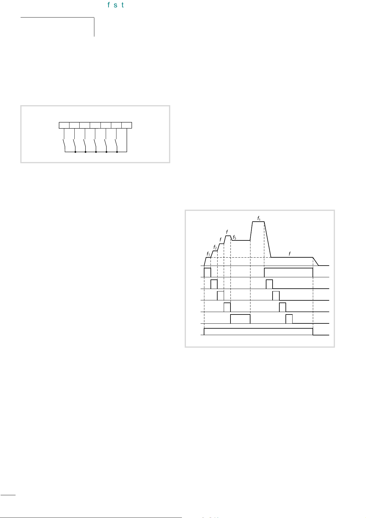
Programming the Control
efesotomasyon.com - Klockner Moeller - inverter
Signal Terminals
01/02 AWB8230-1413GB
Bitwise fixed frequency selection (SF1 to SF7)
With the digital inputs configured as SF1 to SF7, you can directly
access up to seven fixed frequencies. To do this, enter the value 01
under PNU A019 (fixed frequency drive method) and directly
assign a fixed frequency to each of the digital inputs.
SF5
SF4
5
SF3
SF2
SF1
FWD
P24FW1234
Figure 56: Digital inputs 1 to 5 configured as SF1 to SF5 (bitwise fixed
frequency selection).
X Under PNU A019, enter the value 01 to activate the fixed
frequencies SF1 to SF5.
X Program one or more of the digital inputs 1 to 5 as SF1 to SF5
by entering the following values under the corresponding PNU
(C001 to C005).
–SF1: 32
–SF2: 33
–SF3: 34
–SF4: 35
–SF5: 36
–SF6: 37
–SF7: 38
The fixed frequencies can be programmed in two ways:
• entering the fixed frequencies under PNU A021 to A027
(see below),
• entering the fixed frequencies under PNU F001 (see below).
The entered value is saved in the parameter which you have
selected with the digital input. If you have wired the inputs as
shown in figure 56, the value is saved under PNU A021 when
digital input 1 is activated.
X Repeat these steps for your additional fixed frequencies.
Specifying frequency setpoints
The setpoint frequency can be assigned in one of three ways,
depending on PNU A001:
• through the installed potentiometer on the keypad,
PNU A001 = 00;
• through analog input O (0 to 10 V), O2 (–10 V to +10 V) or OI
(4 to 20 mA), PNU A001 = 01 (default);
• through PNU F001 or PNU A020, PNU A001 = 02.
Selecting fixed frequencies
X Select the defined fixed frequencies by activating the respective
digital inputs (a fig. 57).
B
4
B
5
B
3
B
2
B
1
SF1
SF2
SF3
SF4
SF5
B
s
B
1
With PNU F001, you can change parameters even when the
parameter protection (a page 81
Entering the fixed frequencies under PNU A021 to A027
X Go to PNU A021 and press the PRG key.
X Use the arrow keys to enter the fixed frequency and confirm
with the ENTER key.
X Enter the remaining fixed frequencies by repeating these steps
for PNU A022 to A027.
Entering the fixed frequencies under PNU F001
Before you can enter the frequencies under PNU F001, you must
set the value 02 in PNU A001.
X To select a fixed frequency stage, activate the digital input as
listed in figure 56.
X Go to PNU F001.
The current frequency appears on the display.
X Use the arrow keys to enter the fixed frequency and confirm
with the ENTER key.
70
FWD
Figure 57: Function chart for bitwise fixed frequency selection (SF1 to
SF5)
: Setpoint frequency
f
s
You do not have to use all five inputs. You can, for example, set
only one fixed frequency. The priority of the fixed frequencies is
specified through the digital input.
Fixed frequency SF1 has the highest, and SF5 die lowest priority
(a fig. 57).
Page 74
01/02 AWB8230-1413GB
efesotomasyon.com - Klockner Moeller - inverter
.
Start/stop
PNU Name Adjustable in RUN mode Value Function WE
Normal Extended
A001 Defined
frequency
setpoint
A019 Selection of
fixed frequency
actuation
A020
A220
Frequency
setpoint value
A021 Fixed
A022
frequency
A023
...
A027
F001 Input/display
frequency
value
– – 00 Definition with the potentiometer on the keypad 01
01 Definition through analog input O (0 to 10 V), OI
(4 to 20 mA) or O2 (–10 V to +10 V H)
02 Definition via PNU F001 and/or PNU A020
03 Definition through RS 485 serial interface, terminals: RP,
2 x SN and SP
04 Definition via optional card at slot 1
05 Definition via optional card at slot 2
– – 00 Binary (FF1 to FF4) 00
01 Bitwise (SF1 to SF7)
j j 0 to PNU A004 You can enter a frequency setpoint value. You must set
0.0
PNU A001 to 02 for this purpose.
You can assign a frequency to each of the seven fixed
frequency parameters of PNU A021 to A027.
Indication of the current frequency setpoint value or the
current fixed frequency.
To save modified values, press the ENTER key according to
the selection of the digital inputs configured as SF1 to SF7.
Resolution g0.1 Hz
71
Page 75
Programming the Control
efesotomasyon.com - Klockner Moeller - inverter
Signal Terminals
01/02 AWB8230-1413GB
Analog input changeover (AT)
When the digital input configured as AT is active, you can change
over between analog inputs O and OI or between O and O2:
•O: 0 to +10V,
• O2: –10V to +10V,
•OI: 4 to 20mA.
Under PNU A001, enter the setpoint frequency input method. At
the default value of 01, terminals O, O2 and OI are used for
setpoint input.
X If it has not yet been correctly configured, set the PNU A001 to
01.
Under A005, specify whether activation of the AT input results in
a changeover between O and OI or between O and O2.
AT
P245
X Program one of the digital inputs 1 to 5 as AT by entering the
value 16 under the corresponding PNU (C001 to C005).
By default, AT is assigned to digital input 2.
Figure 58: Digital input 5 configured as AT (setpoint definition
through current signal)
PNU Name Adjustable in RUN mode Value Function WE
Normal Extended
A005 AT selection – – 00 Changing over from O to OI 00
01 Changing over from O to O2
A006 O2 selection
– – 00 O2 signal only 00
01 Sum of signals at O2 and O/OI without direction reversal
02 Sum of signals at O2/O or OI with direction reversal
The table below shows how you can link analog inputs O, O2 and
OI with PNU A005 and A006.
Main frequency
setpoint value
input
OYes YesYes 02 00 Off
Add O + OI Yes Yes
O2 No Yes
OI Yes Yes
Input O2 as additive setpoint
frequency input?
No No
Yes No
No No
Reversal with
O2?
No
No
No
Input AT
present?
Yes 01 00 Off
Yes 00 00 Off
No 00 – –
Yes 02 01 On
Yes 02 00 On
A006 A005 Input AT
01
01
00 01
02
01
00
01
01
00
72
Page 76
01/02 AWB8230-1413GB
efesotomasyon.com - Klockner Moeller - inverter
Second time ramp (2CH)
Start/stop
If the digital input configured as 2CH is active, the motor is
FWD/REV
accelerated or braked with the second acceleration or deceleration
time. If the 2CH input is deactivated again, a changeover to the
first acceleration/deceleration time takes place.
2CH
a
b
f
O
2CH
FWD
P2413
Figure 59: Digital input 3 configured as 2CH (second time ramp)
Figure 60: Function chart for 2CH (second acceleration time)
: Output frequency
f
o
a First acceleration time
b Second acceleration time
X Under PNU A092 and PNU A093, set the required value for the
second acceleration and deceleration time.
X Then, set PNU A094 to 00 so that the changeover to the second
acceleration and deceleration time through the 2CH input is
enabled (this is the default setting).
X Program one of the digital inputs 1 to 5 as 2CH, by setting the
corresponding PNU (C001 to C005) to 09.
PNU Name Adjustable in RUN mode Value Function WE
Normal Extended
A092
A292
A093
A293
A094
A294
h
Second
acceleration
time
Second
deceleration
time
Changeover
from the first to
the second
time ramp
j j 0.01 to 3600 s Setting times for the second acceleration and deceleration
– – 00 Changeover to the second time ramp if an active signal is
If you set PNU A094 to 01, the changeover to the second
acceleration or deceleration time can take place
automatically at the frequency set under PNU A095 or
A096 (a section “Time ramps”, page 129).
The value for the first acceleration and deceleration time
h
is defined in PNU F001 and F002 (a section
“Acceleration time 1”,page 105).
15
time
00
present on a 2CH digital input.
01 Changeover to the second time ramp when the frequencies
entered in PNU A095 and/or A096 are reached
73
Page 77
Programming the Control
efesotomasyon.com - Klockner Moeller - inverter
Signal Terminals
01/02 AWB8230-1413GB
Controller inhibit and coasting (free run stop – FRS)
If you activate the digital input configured as FRS, the motor is
switched off and coasts to a stop (for example if an EmergencyStop is made). If you deactivate the FRS input, then, depending on
the inverter’s configuration, the frequency output is either
synchronized to the current speed of the coasting motor or restarts
at 0 Hz.
FRS
FWD
P243FW
Figure 61: Digital input 3 configured as FRS (controller inhibit) and
FW as FWD (start/stop clockwise operation)
FWD/REV
FRS
a
b
X Use PNU b088 to specify whether the motor is to restart at 0 Hz
after the FRS input has been deactivated, or if synchronization
should take place after a waiting time specified under
PNU b003. The frequency inverter recognizes the speed of the
rotor and starts only when the frequency set at PNU b007 is
reached.
X Program one of the digital inputs 1 to 5 as FRS by entering the
value 11 under the corresponding PNU (C001 to C005).
n
M
c
Figure 62: Function chart for FRS (control inhibit and free run stop)
:Motor speed
n
M
: Waiting time (setting under PNU b003)
t
w
a Motor coasts to a stop
b Synchronization to the current motor speed
c Restart from 0 Hz
PNU Name Adjustable in RUN mode Value Function WE
Normal Extended
b003 Waiting time
before restart
b007 Synchronizing
frequency
b088 Motor restart
after removal
of the FRS
signal
– j 0.3 to 100 s Here, set a time which is to expire before an automatic
– j 0 to 400 Hz Frequency at which a restart is initiated. 0.00
– j 00 0 Hz restart after deactivation of the FRS input 00
t
w
restart is initiated after a fault signal. This time can also be
used in conjunction with the FRS function. During the delay,
the following message appears on the LED display:
01 Synchronization of the motor to the frequency set under
PNU 007 after the waiting time set under PNU b003.
1.0
74
Page 78
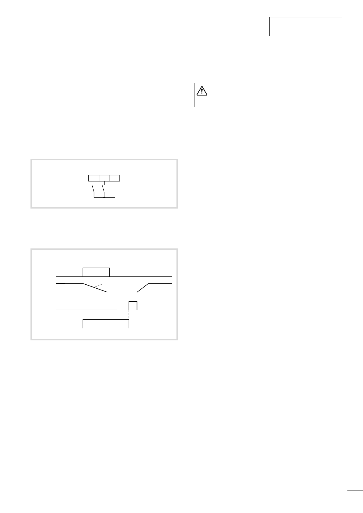
01/02 AWB8230-1413GB
efesotomasyon.com - Klockner Moeller - inverter
Start/stop
External fault message (EXT)
When the digital input configured as EXT is activated, fault
message E12 is issued (for example to be used as input for
thermistor contacts). The fault message remains active even if the
EXT input is deactivated again and must be acknowledged with a
reset.
A reset can be carried out with:
• the RST input or
• the OFF key.
• Alternatively, the supply voltage can be switched off and on
again.
EXT
FWD
P24FW3
Figure 63: Digital input FW configured as FWD (start/stop clockwise
operation) and digital input 3 as EXT (external fault
message)
X Program one of the digital inputs 1 to 5 as EXT by entering the
value 12 under the corresponding PNU (C001 to C005).
Warning!
After a reset, the motor restarts immediately if a start
signal (FWD or REV) is active.
FWD/REV
EXT
a
n
M
RST
K14
Figure 64: Function chart for EXT (external fault message)
: Motor speed
n
M
K14: Signalling relay contact K14
(if the signalling relay has been set to 13 (THM) under PNU C026
a Motor coasts to a stop
75
Page 79
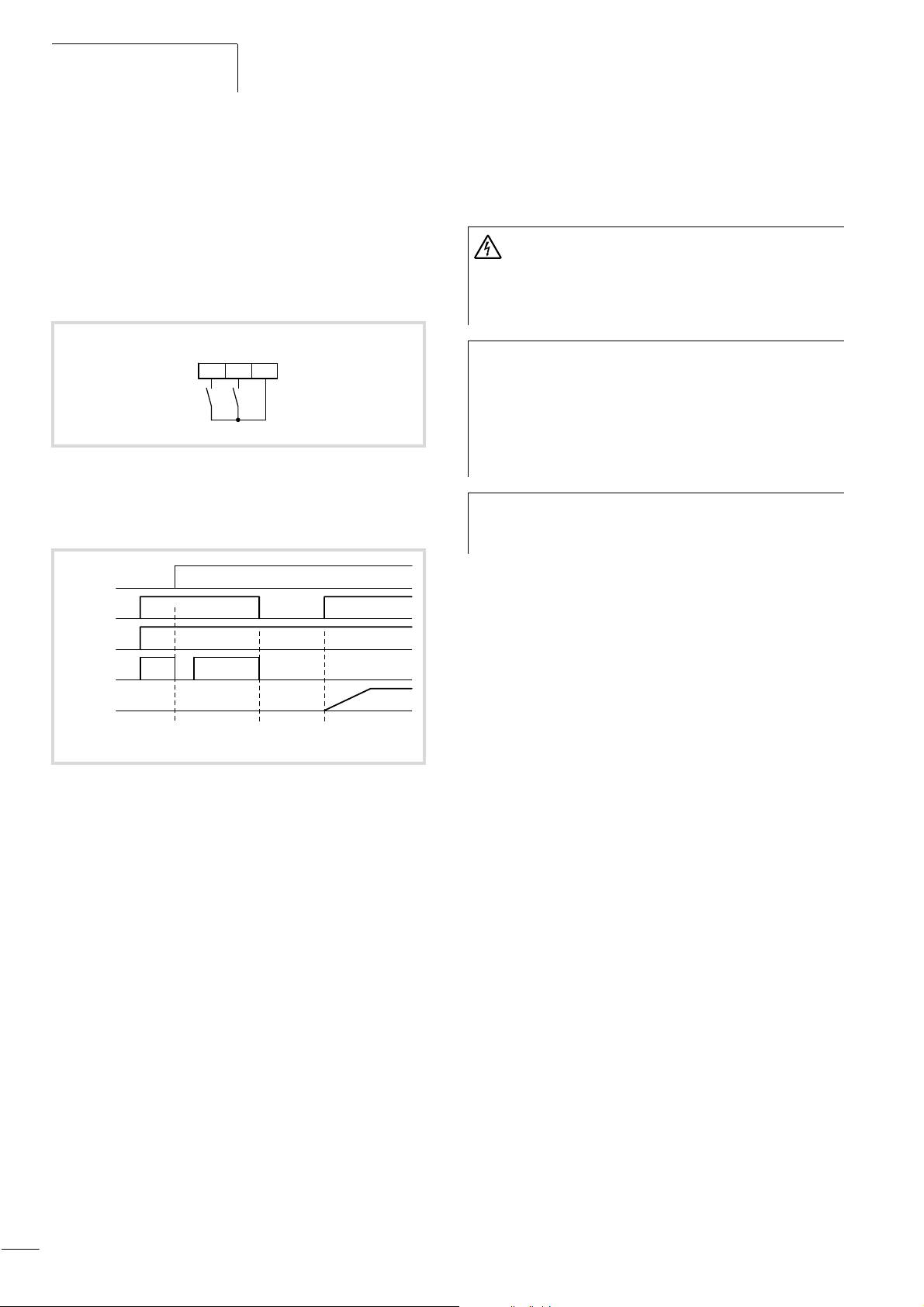
Programming the Control
efesotomasyon.com - Klockner Moeller - inverter
Signal Terminals
01/02 AWB8230-1413GB
Unattended start protection (USP)
If the digital input configured as USP is activated, unattended start
protection is also activated. This prevents a restart of the motor
when the voltage recovers after a mains fault while a start signal
(active signal on FWD or REV) is present. Fault message E13 is
issued. E13 is cancelled by pressing the OFF key or with an active
signal on the RST input. Alternatively, the start signal can be
revoked.
USP
FWD
P24FW3
Figure 65: Digital input configured as FWD (start/stop clockwise
operation) and digital input 3 as USP (unattended start
protection).
U
N
X Program one of the digital inputs 1 to 5 as USP by setting the
corresponding PNU (C001 to C005) to 13.
Warning!
If unattended start protection is triggered (fault message
E13) and the fault message is acknowledged with a reset
command while a start signal is still active (input FWD or
REV active), the motor will restart immediately.
If you issue a start signal within three seconds of
h
reestablishing the power supply and unattended start
protection is active, the unattended start protection is
also triggered and issues fault message E13. When
unattended start protection is used, you should therefore
wait for at least three seconds before issuing a start signal
to the frequency inverter.
Unattended start protection can still be activated when
h
you issue a reset command through the RST input after an
undervoltage fault message (E09) has occurred.
FWD/REV
USP
K14
f
O
E13
Figure 66: Function chart for USP (unattended start protection)
:Supply voltage
V
N
K14: Signalling relay contact K14
: Output frequency
f
o
a Revoke start signal (alarm no longer present)
b Start signal
a
b
76
Page 80
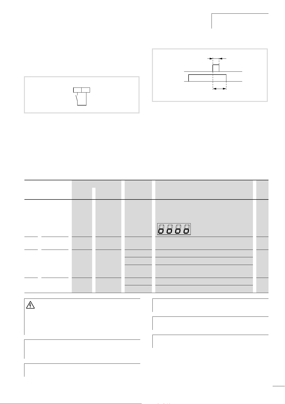
01/02 AWB8230-1413GB
efesotomasyon.com - Klockner Moeller - inverter
Start/stop
Reset (RST)
A fault message can be acknowledged by activating and
f 12 ms
subsequently deactivating (i.e. resetting) the digital input
configured as RST.
RST
P244
Figure 68: Function chart for RST (reset)
K14: Signalling relay contact K14
Figure 67: Digital input 4 configured as RST (reset)
X Program one of the digital inputs 1 to 5 as RST by entering the
RST
K14
~ 30 ms
value 18 under the corresponding PNU (C001 to C005).
By default, RS is assigned to digital input 1.
Under PNU C103, you can select how the frequency inverter
responds after the reset signal drops out. You can specify whether
the frequency inverter synchronizes to the frequency set under
PNU b007 or starts at 0 Hz.
PNU Name Adjustable in RUN mode Value Function WE
Normal Extended
b003 Waiting time
before restart
b007 Synchronizing
frequency
C102 Reset signal
C103 Behaviour on
reset
– j 0.3 to 100 s Here, set a time which is to expire before an automatic
– j 0 to 400 Hz Frequency at which a restart is initiated. 0.0
j j 00 Reset signal issued on a rising edge 00
– j 00 0 Hz start 00
Warning!
If a reset is carried out after a fault, the motor will start
immediately if a start signal is applied simultaneously. To
avoid the risk of serious or fatal injury to personnel, you
must ensure that the start signal is not present before
acknowledging an error message with a reset .
When a fault has occurred, the OFF key on the keypad
h
acts as a RESET key, and can be used instead of the RST
input to reset the fault.
restart is initiated after a fault signal. This time can also be
used in conjunction with the FRS function. During the delay,
the following message appears on the LED display:
01 Reset signal issued on a falling edge
02 Reset signal issued on a rising edge, only if fault signal
present
01 Synchronization to the motor speed
The RST input is always a make (NO) contact and cannot
h
be programmed as a break (NC) contact.
Alternatively, you can acknowledge a fault message by
h
briefly switching the supply voltage off and on again.
If a reset is initiated during operation, the motor coasts to
h
a stop.
1.0
If the RST input is active for more than four seconds, it can
h
cause a false trip.
77
Page 81
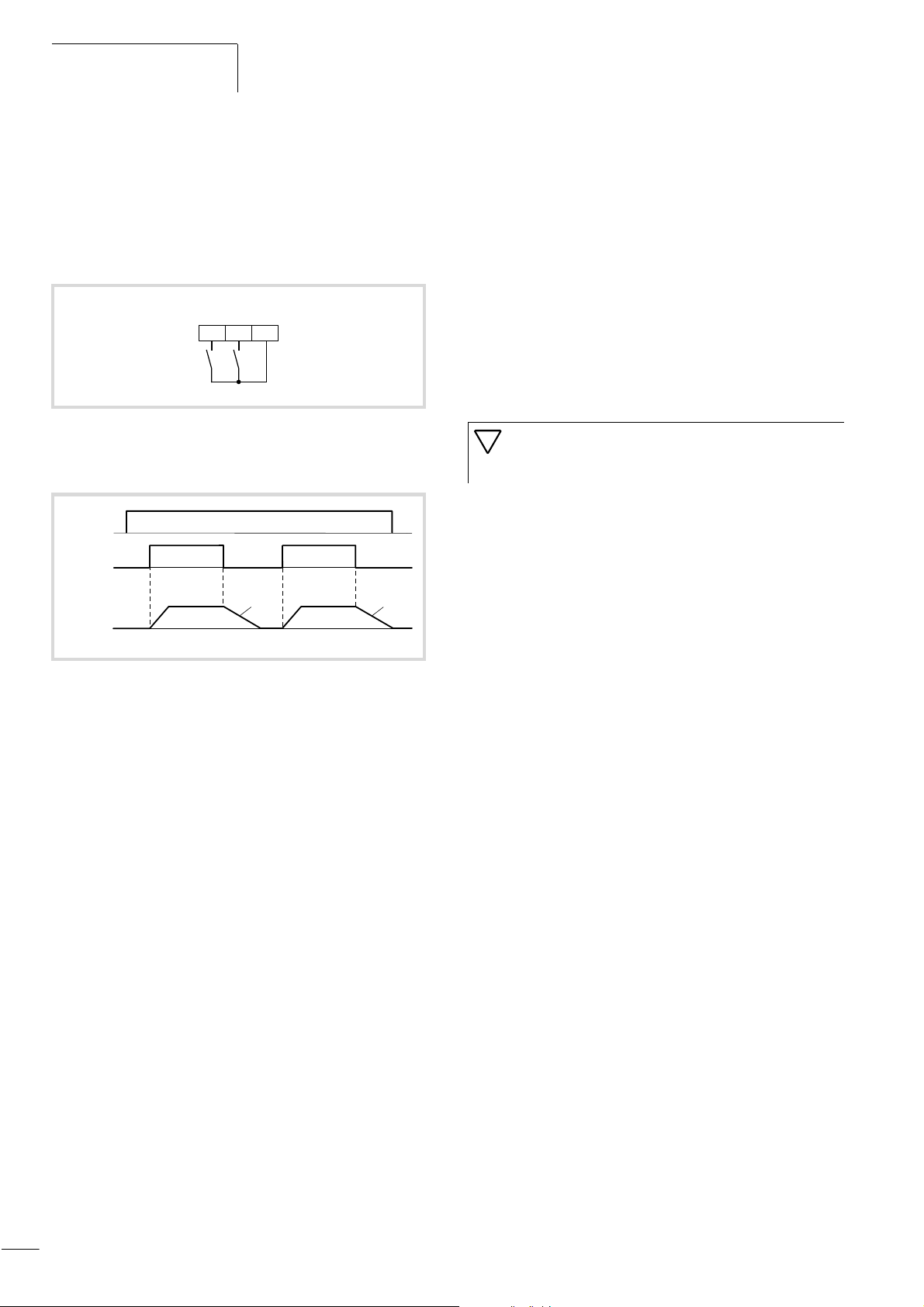
Programming the Control
efesotomasyon.com - Klockner Moeller - inverter
Signal Terminals
01/02 AWB8230-1413GB
Jog mode (JOG )
When the digital input configured as JOG is activated, the motor
can be operated in jog mode. This mode is used, for example, for
manual setting up of a machine by issuing a start signal on the FW
or REV input with a relatively low frequency without applying an
acceleration ramp to the motor.
JOG
FWD
P24FW3
Figure 69: Digital input FW configured as FWD (start/stop clockwise
operation) and digital input 3 as JOG (jog operation)
JOG
FWD/REV
a
n
M
a
X First, under PNU A038, enter
the frequency which is to be applied to the motor when jog
mode is active.
Make sure that the frequency is not too high, as it is applied
directly to the motor without an acceleration ramp. This could
cause a fault message. Set a frequency below 5 Hz.
X Because the start signal is issued through the FWD or REV input
in jog mode, PNU A002 must be set to 01.
X Under PNU A039, you determine how the motor is to be braked.
X Program one of the digital inputs 1 to 5 as JOG by entering the
value 06 under the corresponding PNU (C001 to C005).
Caution!
Make sure that the motor has stopped before using
jog mode.
Figure 70: Function chart for JOG (jog mode)
n
:Motor speed
M
a Depending on the setting of PNU A039
00: Coasting
01: Deceleration ramp
02: DC braking
78
Page 82
01/02 AWB8230-1413GB
efesotomasyon.com - Klockner Moeller - inverter
PNU Name Adjustable in RUN mode Value Function WE
Normal Extended
Start/stop
A002 Start signal – – 01 The signal for starting the motor is issued through the digital
inputs configured as FW or REV.
02 The signal for starting the motor is issued by the ON key on
the keypad.
A038 Frequency in
jog mode
A039 Type of motor
stop in jog
mode
Operation in jog mode is not possible when the jogging
h
j j 0 to 9.99 Hz The frequency to be applied to the motor in jog mode. 1.0
– j 00 Stop signal active: the motor coasts to halt 00
01 Stop signal active: the motor is decelerated to standstill
under a deceleration ramp
02 Stop signal active: the motor is decelerated to standstill
under DC braking
03 Jog mode without prior motor stop: the motor coasts to halt
04 Jog mode without prior motor stop: the motor is decelerated
to standstill under a deceleration ramp
05 Jog mode without prior motor stop: the motor is decelerated
to standstill under DC braking
frequency set under PNU A038 is less than the start
frequency set under PNU b082 (a section “Run signal
(RUN)”, page 96).
01
Jog mode can only be activated when the frequency
h
inverter is in the Stop state if the values 00 to 02 have
been set under PNU C039.
79
Page 83
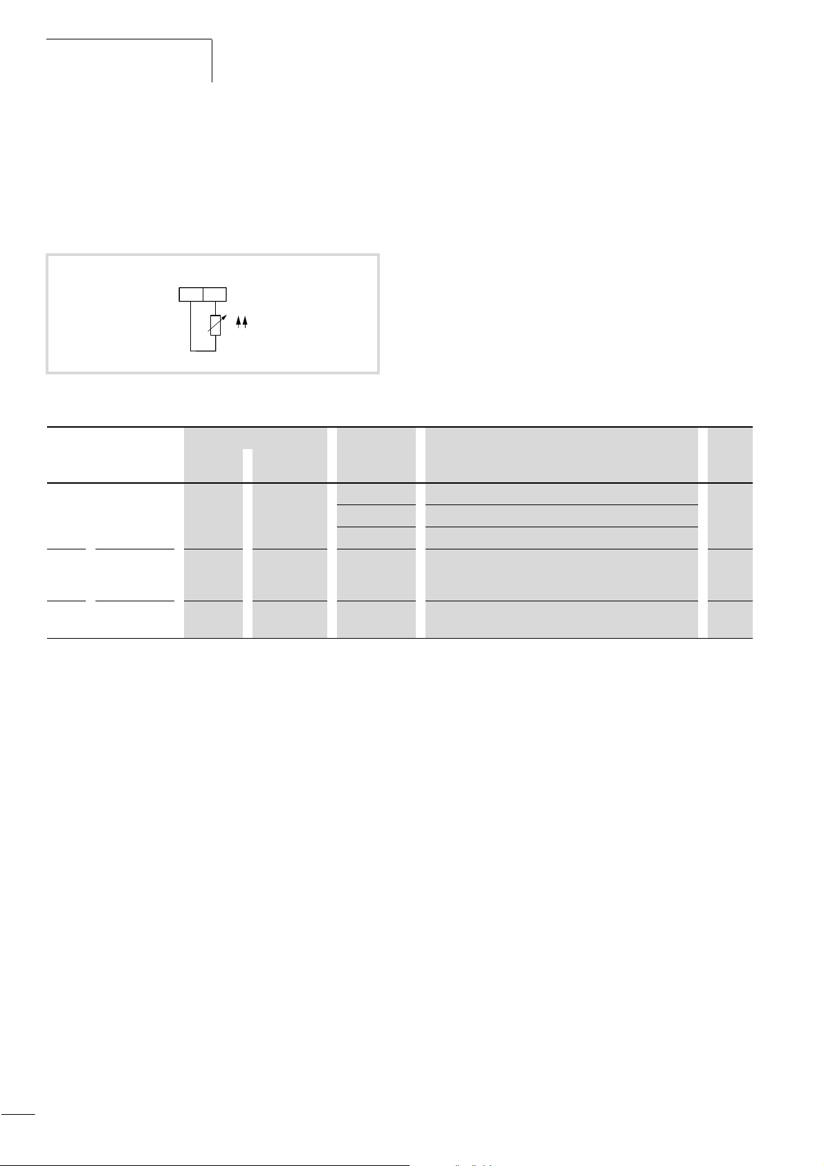
Programming the Control
efesotomasyon.com - Klockner Moeller - inverter
Signal Terminals
01/02 AWB8230-1413GB
PTC/NTC thermistor input, terminal TH
You can monitor the motor temperature during operation using
analog input TH in connection with CM1 (chassis). You can
connect either a PTC or an NTC thermistor to this input. This is
defined under PNU b098. Under PNU b099, enter the resistance at
which the device is switched off.
PTC
THCM1
i
Figure 71: Connection, terminal TH
PNU Name Adjustable in RUN mode Value Function WE
Normal Extended
b098 PTC/NTC
selection
b099 Resistance
threshold
deactivation
C085 Thermistor
matching
X To connect a thermistor, use a twisted cable and lay this cable
– j 00 No temperature monitoring 00
01 PTC
02 NTC
– j 0 to 9999 O When the entered value is reached, the input terminal is
j j 0.0 to 1000 Scaling factor for input terminal TH. 105
separately.
3000 O
activated.
80
Page 84
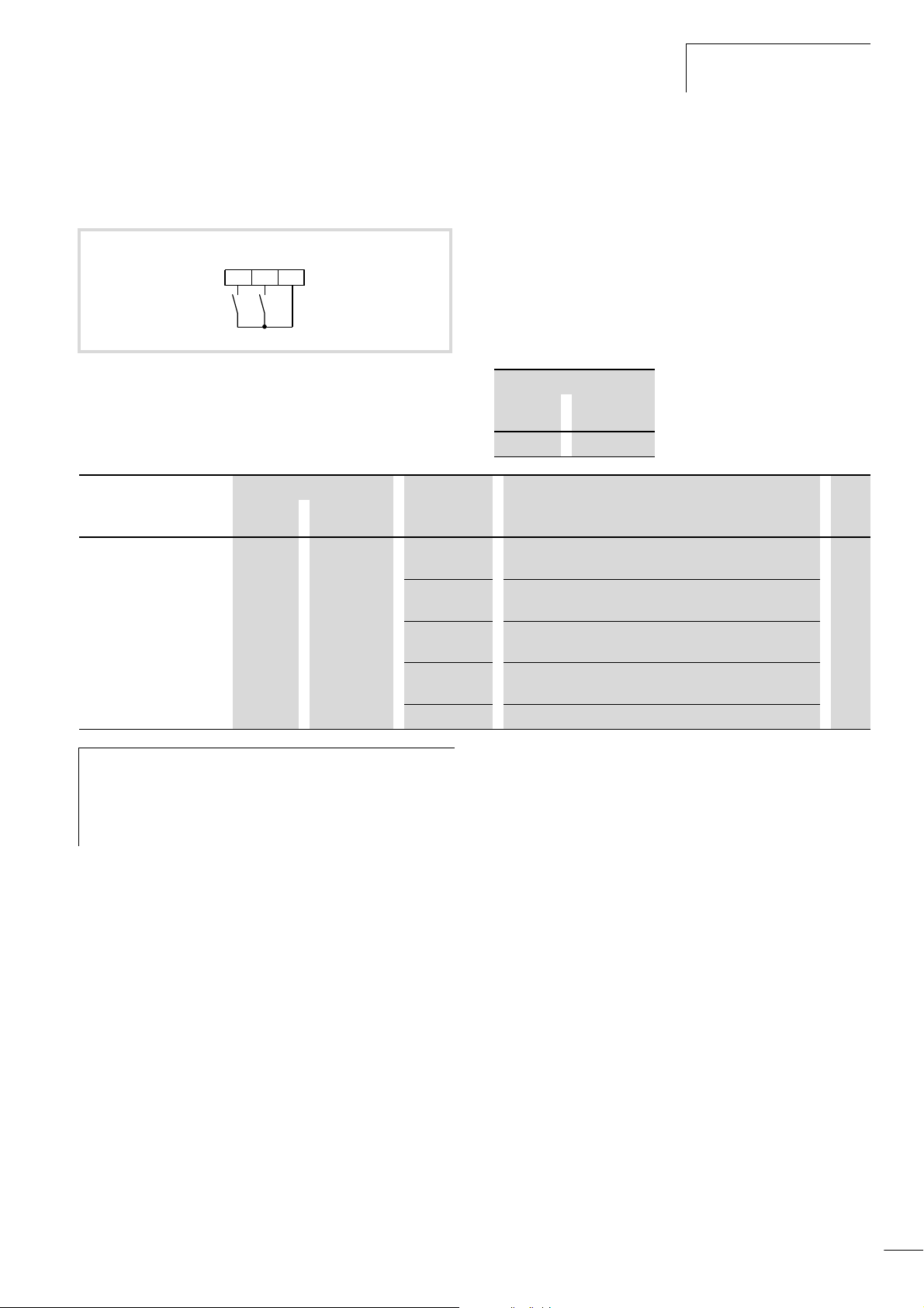
01/02 AWB8230-1413GB
efesotomasyon.com - Klockner Moeller - inverter
Start/stop
Software protection (SFT)
When you activate the digital input configured as SFT, the
configured parameters cannot be overwritten unintentionally.
SFT
FWD
P24FW3
X With PNU b031, specify whether software protection will also
apply to the frequency setting under PNU F001.
X Then, program one of the digital inputs 1 to 5 as SFT by setting
the corresponding PNU (C001 to C005) to 15.
Under PNU b031, you can specify whether you want to use the
normal or extended parameter setting features in RUN mode. If
you set the value 10 under PNU b031, further parameters are
available which can be modified in the RUN mode. These
additional parameters are marked “j” in the “Extended”
column.
Figure 72: Digital input 3 configured as SFT (software protection)
PNU Name Adjustable in RUN mode Value Function WE
Normal Extended
b031 Software-
dependent
parameter
protection
– j 00 Software protection through SFT input;
01 Software protection through SFT input;
02 Software protection without SFT input;
03 Software protection without SFT input;
10 Extended parameters adjustable in RUN mode
Adjustable in RUN mode
Normal Extended
– j
all functions inhibited
input through PNU F001 possible
all functions inhibited
input through PNU F001 possible
01
There is, however, an alternative method of software
h
protection available which does not require an SFT input.
For this, enter the value 02 or 03 under PNU b031
depending on whether software protection should also
apply to the frequency setting under PNU F001 or not.
81
Page 85
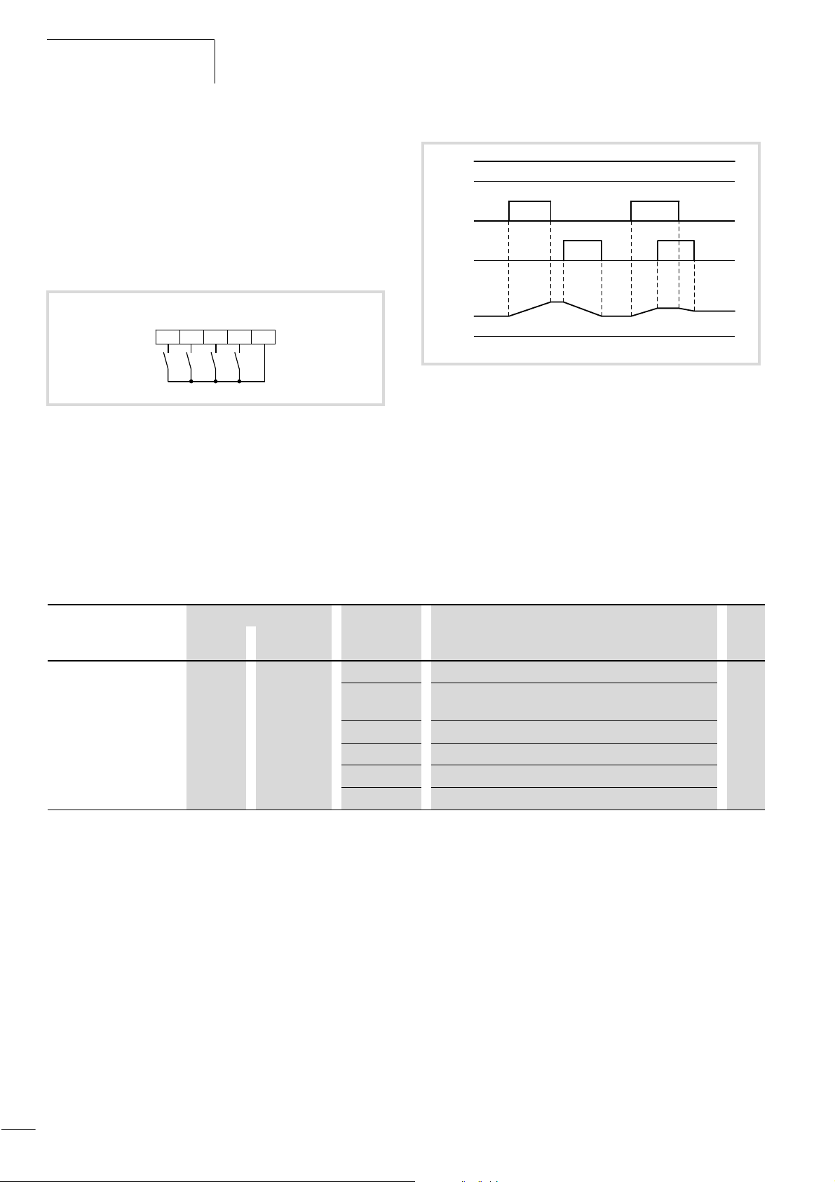
Programming the Control
efesotomasyon.com - Klockner Moeller - inverter
Signal Terminals
Motor potentiometer functions: accelerate (UP) – decelerate (DWN) – reset frequency (UDC)
Accelerate (UP) and decelerate (DWN)
If you configure one of the programmable digital inputs as UP or
DWN (or two programmable digital inputs as UP and DWN), an
additional acceleration (with the UP input active) or deceleration
(with the DWN input active) can be carried out, starting with the
specified frequency setpoint.
DWN
REV
5
Figure 73: Digital input FW configured as FWD (start/stop clockwise
operation), 3 as UP (accelerate), 4 as DWN (decelerate)
and 5 as REV (start/stop anti clockwise operation)
UP
FWD
P24FW34
01/02 AWB8230-1413GB
REV
UP
DWN
f
O
Figure 74: Function chart for UP/DWN (acceleration/deceleration –
motor potentiometer)
: Output frequency
f
o
X Because the terminal functions UP and DWN can be used only
when the frequency setpoint has been specified with PNU F001
or A020, you need to make sure that PNU A001 contains the
value 02.
X Then, program one or two of the digital inputs 1 to 5 as UP or
DWN by setting the corresponding PNU (C001 to C005) to 27
or 28.
PNU Name Adjustable in RUN mode Value Function WE
Normal Extended
A001 Defined
frequency
setpoint
The UP/DWN function is not available when jog mode has been
activated (with active JOG input) or when the frequency setpoint
definition is made through the analog input terminals.
The output frequency range for UP and DWN ranges from 0 Hz up
to the end frequency specified under PNU A004 (a section “End
frequency”, page 108).
– – 00 Definition with the potentiometer on the keypad 01
01 Definition through analog input O (0 to 10 V) or OI
(4 to 20 mA)
02 Definition through PNU F001 and/or PNU A020
03 Definition through RS 485
04 Definition through slot 1 for optional module
05 Definition through slot 2 for optional module
Reset frequency (UDC)
If you configure one of the programmable digital inputs as UDC,
you can use this input to reset the frequency set with the motor
potentiometer to 0 Hz. PNU A020 is then reset to 0 Hz.
X Program one of the digital inputs 1 to 5 as UDC by entering the
value 29 under the corresponding PNU (C001 to C005).
The shortest permissible duration during which an UP or DWN
input must be active is 50 ms.
Through the use of the input configured as UP, the frequency
setpoint set under PNU A020 is also increased or, with DWN,
reduced (a fig. 74).
82
Page 86

01/02 AWB8230-1413GB
efesotomasyon.com - Klockner Moeller - inverter
Start/stop
Behaviour on restart
With PNU C101, you can specify whether the frequency defined
with UP/DWN, or the original frequency entered under PNU A020
is used when the DF6 frequency inverter is restarted.
PNU Name Adjustable in RUN mode Value Function WE
Normal Extended
C101 Use memory – j 00 Use original frequency set under PNU A020 00
01 Use saved UP/DWN setting
83
Page 87
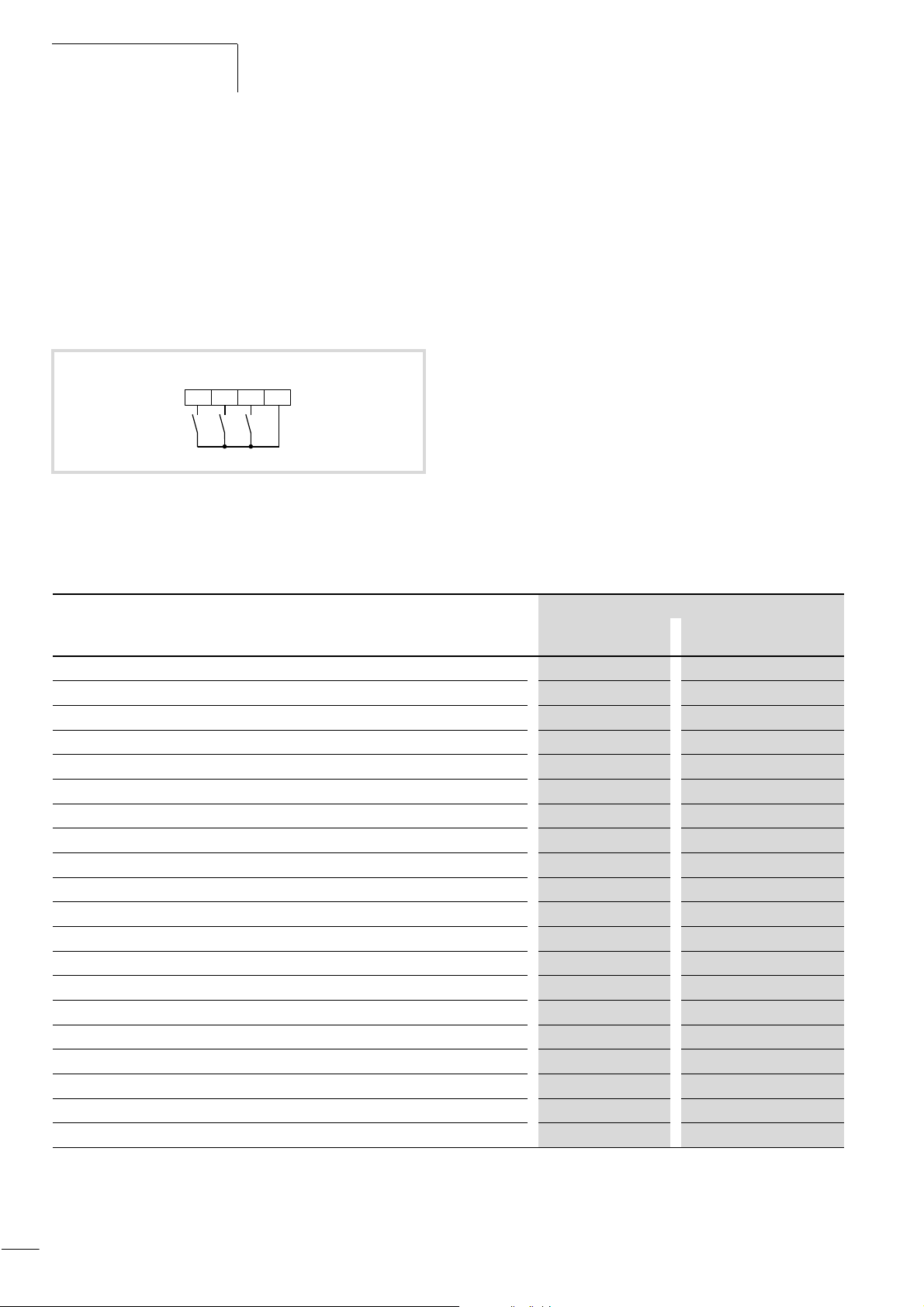
Programming the Control
efesotomasyon.com - Klockner Moeller - inverter
Signal Terminals
01/02 AWB8230-1413GB
Use second parameter set (SET)
When the digital input configured as SET is active, the parameters
from the second parameter set are used. This allows you to
operate a second motor with the same frequency inverter (albeit
not at the same time) without having to reprogram the frequency
inverter. The functions which are also available in the second
parameter set are listed in table 16.
As soon as the SET input is deactivated, the normal parameters of
X Program one of the digital inputs 1 to 5 as SET, by setting the
corresponding PNU (C001 to C005) to 08.
The motor must have come to a standstill before the SET input is
activated.
If the SET input is deactivated while the motor is in operation, the
parameters of the second parameter set are used until the motor
is stationary again.
the default parameter set are used.
REV
Figure 75: Digital input FW configured as FWD (start/stop clockwise
operation), 3 as SET (use second parameter set) and 5 as
REV (start/stop anticlockwise operation)
Table 16: Functions with second parameter set
Description of the function Parameter number (PNU)
SET
FWD
P24FW35
Default second parameter set
First acceleration time F002 F202
First deceleration time
Base frequency
Maximum end frequency
Frequency setpoint (PNU A001 must be 02 for this)
Voltage boost characteristics
Percentage voltage increase with manual boost
Maximum boost relative to the base frequency
V/f characteristic
Maximum operating frequency
Minimum operating frequency
Second acceleration time
Second deceleration time
Type of changeover from first to second time ramp
Changeover frequency for changeover from first to second acceleration time
Changeover frequency for changeover from first to second deceleration time
Tripping current for electronic motor protection device
Characteristic for electronic motor protection device
Motor rating
Number of motor poles
F003 F203
A003 A203
A004 A204
A020 A220
A041 A241
A042 A242
A043 A243
A044 A244
A061 A261
A062 A262
A092 A292
A093 A293
A094 A294
A095 A295
A096 A296
b012 b212
b013 b213
H003 H203
H004 H204
84
Page 88
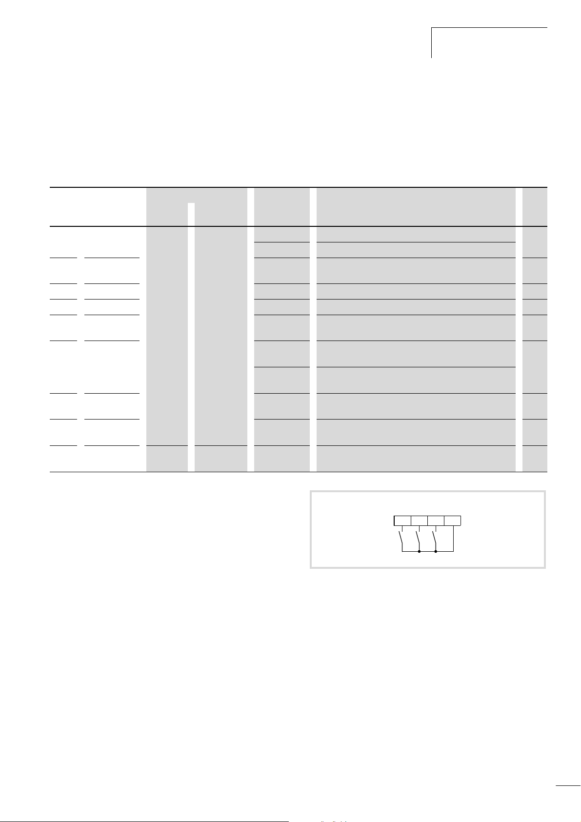
01/02 AWB8230-1413GB
efesotomasyon.com - Klockner Moeller - inverter
Start/stop
Activate DC braking (DB)
DC braking can be activated either through a digital input
configured as DB or automatically when a specific frequency is
reached.
X Program one of the digital inputs 1 to 5 as DB by entering the
value 07 under the corresponding PNU (C001 to C005).
PNU Name Adjustable in RUN mode Value Function WE
Normal Extended
A051 DC braking – j 00 Inactive 00
01 Active
A052 Activation
frequency
A053 Waiting time
A054 Braking torque
A055 Braking
duration
A056 Characteristic
A057 Starting
braking torque
A058 Starting
braking time
A059 Pulse
frequency
– – 0.5 to 12 kHz DC braking pulse frequency 5
0 to 60 Hz When this frequency is reached, the waiting time PNU A053
begins.
0 to 5 s DC braking begins after the time set here. 0.0
0 to 100% Applied DC braking torque 0
0 to 60 s This time starts when the waiting time entered under
PNU A53 has expired.
00 DC braking starts when the DB input is activated and ends
when the time defined under PNU A055 has expired.
01 DC braking starts when the DB input is activated and ends
when the DB input is deactivated.
0 to 100% Braking torque applied on initial brake application 0
0 to 60 s Braking time before acceleration 0.0
0.50
0.0
01
X For automatic braking, enter 01 under PNU A051.
X Under PNU A052, enter the frequency at which DC braking is
activated.
X Under PNU A053, enter the waiting time which is to expire after
activation of the DB input before DC braking is activated.
X Under PNU A054, enter the braking torque between 0 and
100 %.
X Under PNU A055, enter the braking duration.
X Under PNU A056, specify the braking behaviour when the DB
input is active.
X Under PNU A057, enter the starting braking torque (0 to
100 %) for braking the motor before acceleration.
X Under PNU A058, enter the duration for which DC braking is
active before acceleration.
X Under PNU A059, set the pulse frequency (observe derating
above 5 kHz) for DC braking.
REV
Figure 76: Digital input FW configured as FWD (start/stop clockwise
operation), 3 as (DC braking) and 5 as REV (start/stop
anticlockwise operation)
DB
FWD
P24FW35
85
Page 89
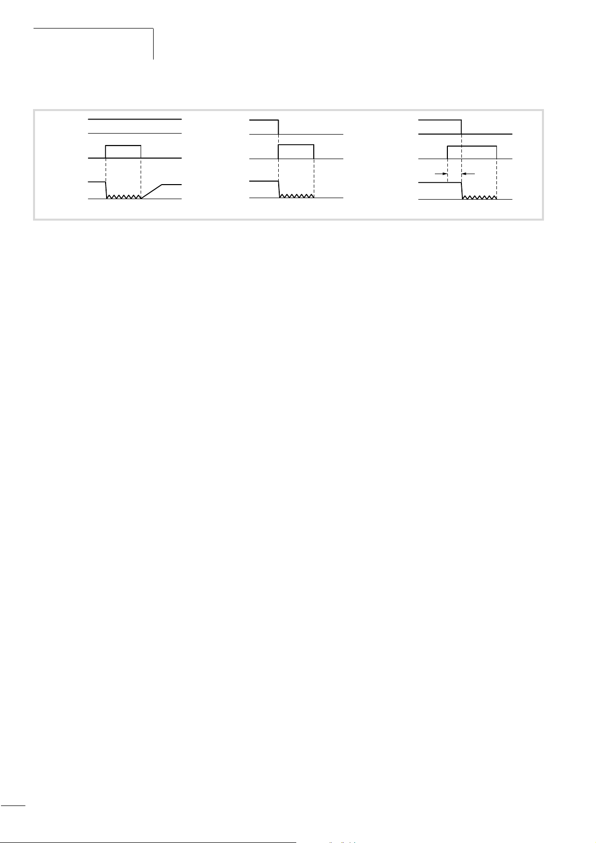
Programming the Control
efesotomasyon.com - Klockner Moeller - inverter
Signal Terminals
01/02 AWB8230-1413GB
FWD/REV
DB
f
O
a
DB
f
O
Figure 77: Function chart for DB (DC braking)
: Output frequency
f
o
a Start signal through keypad
X Program one of the digital inputs 1 to 5 as DB by entering the
value 07 under the corresponding PNU (C001 to C005).
X In PNU A053, enter a delay time t (a fig. 77) from 0 to 5.0 s,
which is to expire before DC braking takes effect after activation
of the DB input.
X Under PNU A054, set a braking force between 0 % and 100 %.
a
DB
t
f
O
86
Page 90
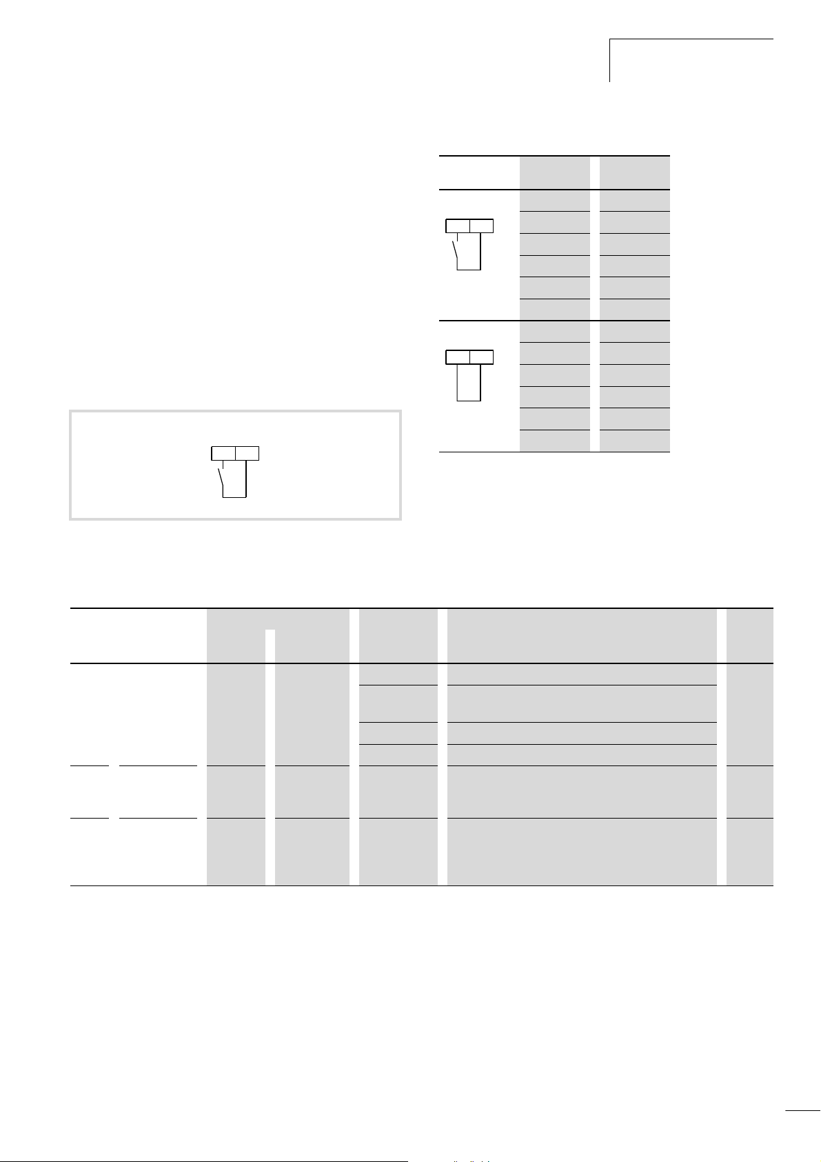
01/02 AWB8230-1413GB
efesotomasyon.com - Klockner Moeller - inverter
Start/stop
Change over current limit (OLR)
The frequency inverter monitors the motor current during
acceleration and/or static operation. When the inverter reaches
the overload limit, the output frequency is reduced to limit the
load. This prevents a shutdown due to overcurrent caused by an
excessive moment of inertia or sudden changes in the load torque.
You can define two different overload behaviours:
• PNU b021 to b023 or
• PNU b024 to b026.
By default, the values of PNU b021 to b023 are used. To use
PNU b024 to b026, activate the digital input configured as OLR
(change over current limit) (a fig. 78 and table 17).
Under PNU b021/b024, you can define the overload limit.
OLR
P243
Figure 78: Digital input 3 configured as OLR
(change over current limit)
Table 17: Changing over the current limit
OLR PNU Active
OLR
P243
OLR
P243
X Under PNU b021 to b023, define the overload behaviour for
b021 j
b022 j
b023 j
b024 –
b025 –
b026 –
b021 –
b022 –
b023 –
b024 j
b025 j
b026 j
your first instance.
X Under PNU b024 to b026, define the overload behaviour for
your second instance.
X Program one of the digital inputs 1 to 5 as OLR by entering the
value 39 under the corresponding PNU (C001 to C005).
PNU Name Adjustable in RUN mode Value Function WE
Normal Extended
b021/
b024
b022/
b025
b023/
b026
Current limit
characteristic
Tripping
current
Time constant – j 0.1 to 30.0 s When the set current limit is reached, the frequency is
– j 00 Motor current limit not active 01
01 Motor current limitation active on acceleration and
constant speed
02 Motor current limitation active at constant speed
03 Motor current limit active in all operating states
– j 0.5 to 2.0 x Ie Setting range of the tripping current as a multiple of the
frequency inverter rated current, i.e. the range is given in
amperes (A).
reduced to 0 Hz in the time set here.
Caution: If possible, do not enter a value less than 0.3
here!
1.2 x I
1.00
e
87
Page 91
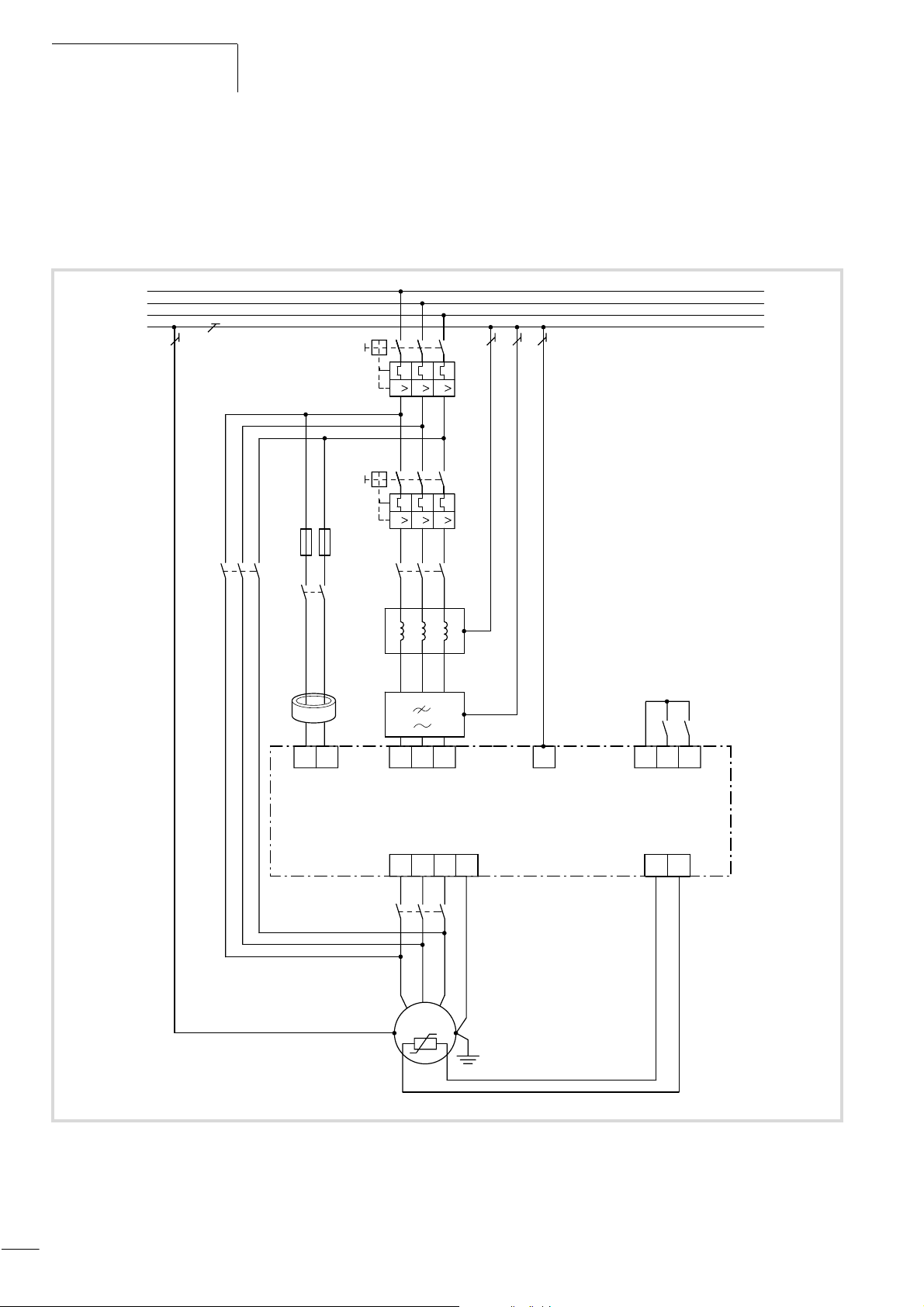
Programming the Control
efesotomasyon.com - Klockner Moeller - inverter
Signal Terminals
01/02 AWB8230-1413GB
Heavy mains starting (CS)
The CS function is used for starting drives with an extremely high
starting torque directly from the mains. This means that a smaller,
less expensive frequency inverter can be used, since the DF6 has
L1
L2
L3
PE
Q1
Q11
F11
K2M
K11
K1M
L1
to deliver only the motor full load current, not the high starting
current (for example 50 A starting current, 15 A motor full load
current).
To use this function, the system must be wired as shown in
figure 79.
531
III
531
III
L3L2L1
PE
Z2
DF6-340-...
DV6-340-...
Z1
K3M
M1
L1 L2 L3
L1 L2 L3
V
U
M 3 h
PE
P24 FW
W
PE
CM1
FWD
TH
2PER0 T0
CS
e
Figure 79: DF6 series frequency inverters with K2M bypass contactor, K3M motor contactor and K1M mains contactor
F11: 6 A miniature circuit-breaker, for example FAZ-B6
88
Page 92
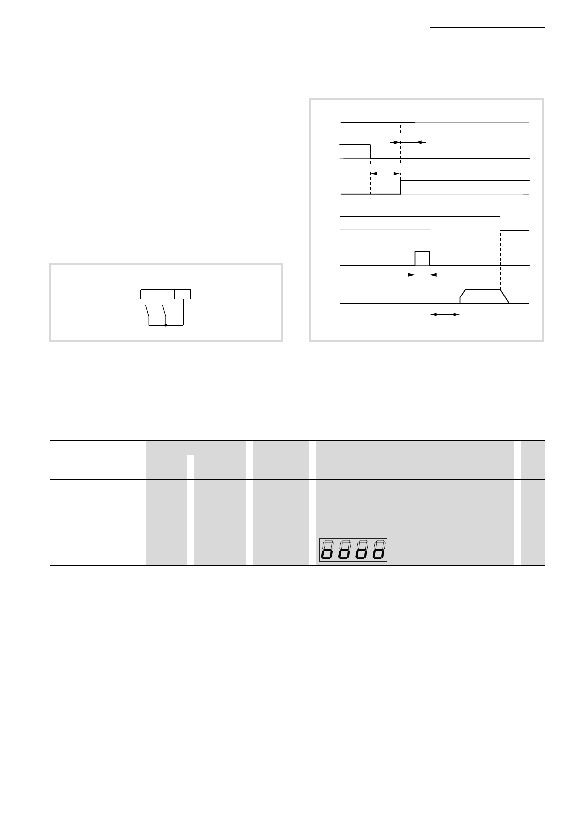
01/02 AWB8230-1413GB
efesotomasyon.com - Klockner Moeller - inverter
Actuation of the contactors consists of the following steps:
Start/stop
• The startup takes place through the K2M bypass contactor.
• Once the motor has accelerated, switch the K2M bypass
contactor off and, with a delay (of 0.5 to 1.0 s), activate the
K3M motor contactor.
• Then, switch the K1M mains contactor on and, at the same
time, activate the digital input configured as CS.
• When the CS input is deactivated, the waiting time set under
PNU b003 begins.
• Once this time has expired, the DF6 frequency inverter
synchronizes to the motor speed and continues to run the
motor.
CS
FWD
P24FW3
Figure 80: Digital input configured FW as FWD (start/stop clockwise
operation) and 3 as CS (heavy mains starting)
K1M
f 0.5 s
K2M
K3M
FW
CS
f
o
0.5 – 1.0 s
f 20 ms
PNU b003
Figure 81: Function chart for CS (heavy mains starting)
X Program one of the digital inputs 1 to 5 as CS by entering the
value 14 under the corresponding PNU (C001 to C005).
PNU Name Adjustable in RUN mode Value Function WE
Normal Extended
b003 Waiting time
before restart
– j 0.3 to 100 s Here, set a time which is to expire before an automatic
restart is initiated after the supply voltage is connected. This
1.0
time can also be used in conjunction with the FRS function.
During the delay, the following message appears on the LED
display:
89
Page 93
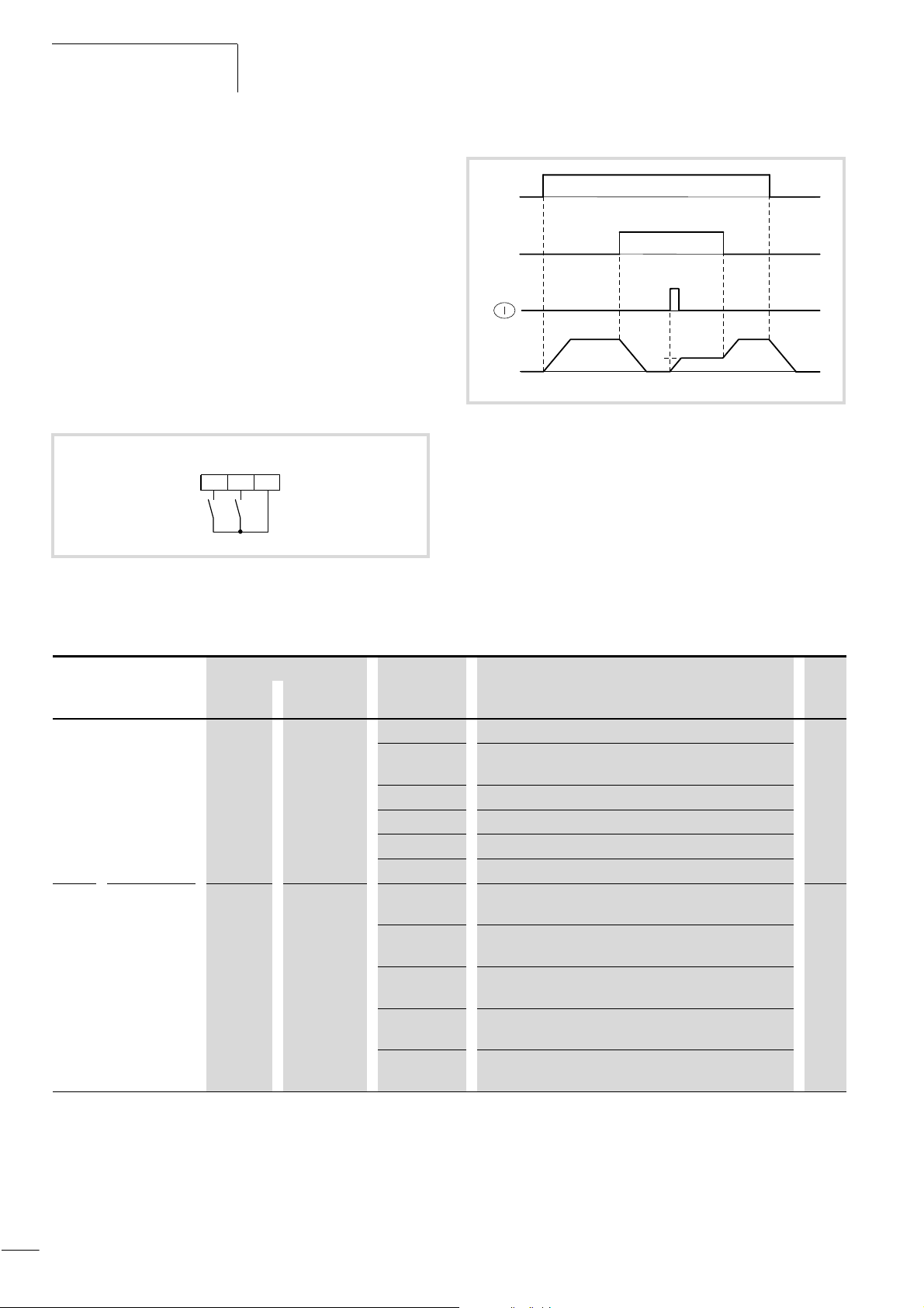
Programming the Control
efesotomasyon.com - Klockner Moeller - inverter
Signal Terminals
Setpoint value through keypad (OPE)
01/02 AWB8230-1413GB
When you activate the digital input configured as OPE, an Enable
signal must be issued with the ON key on the keypad. If, for
example, you have entered the value 01 under PNU A001
(frequency setpoint input through analog input) and the value 01
under PNU A002 (start signal through digital input), these settings
become invalid as soon as you activate the OPE input. PNU A002
then contain the value 02 (start signal through ON key) and the
setpoint frequency under PNU A020 or PNU F001 becomes active.
If you activate the OPE input while the inverter is in RUN mode, it
decelerates and can then be started with the ON key on the device.
If the start signal is still active, the frequency inverter accelerates
to the previously set frequency again as soon as you deactivate the
OPE input.
OPE
FWD
P24FW1
Figure 82: Digital input 1 configured as OPE
(setpoint definition through keypad)
FW
OPE
PNU A020/
F001
f
o
Figure 83: Function chart for OPE
(setpoint definition through keypad)
: Output frequency
f
o
X Program one of the digital inputs 1 to 5 as OPE by entering the
value 31 under the corresponding PNU (C001 to C005).
PNU Name Adjustable in RUN mode Value Function WE
Normal Extended
A001 Frequency
setpoint
definition
A002 Start signal
– – 00 Definition with the potentiometer on the keypad 01
01 Definition through analog input O (0 to 10 V), O2 (g10 V) or
OI (4 to 20 mA)
02 Definition through PNU F001 and/or PNU A020
03 Definition through RS 485 serial interface
04 Setpoint definition through the optional module in slot 1
05 Setpoint definition through the optional module in slot 2
– – 01 The motor start signal is issued through the FW input or a
digital input configured as REV.
02 The signal for starting the motor is issued by the ON key on
the keypad.
03 The motor start signal is issued through the RS 485
interface.
04 The motor start signal is issued through the optional module
in slot 1.
05 The motor start signal is issued through the optional module
in slot 2.
01
90
Page 94
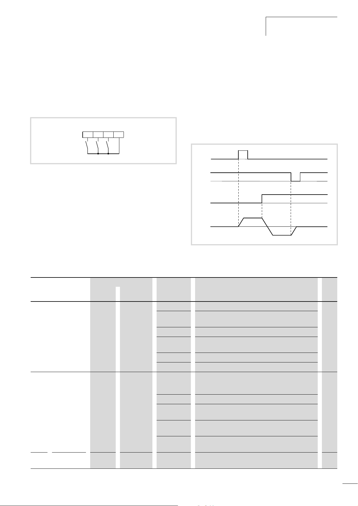
01/02 AWB8230-1413GB
efesotomasyon.com - Klockner Moeller - inverter
Start/stop
Three-wire control (STA – STP – F/R)
With digital inputs configured as STA, STP and F/R, you can
operate the DF6 frequency inverter with three switches:
• STA: Start
• STP: Stop
• F/R: Reverse direction
F/R
Figure 84: Digital input 1 configured as STA (pulse start), digital input
2 as STP (Pulse stop) and digital input 3 as F/R (reverse
direction).
X Program three of digital inputs 1 to 5 as STA, STP and F/R by
STP
STA
P24123
entering the following values under the corresponding PNU
(C001 to C005):
– STA: 20
– STP: 21
–F/R: 22
The DF6 frequency inverter accelerates to the setpoint frequency
entered under PNU A020.
X Under PNU A001, enter the value 02 (setpoint definition
through PNU A020).
X Under PNU A002, enter the value 01 (start signal through
digital inputs).
X Under PNU A020, enter the setpoint frequency.
If you want to start the inverter through the STA input, the STP
input must be activated (inverse function, fail-safe). The signal
must be applied for only a short time (pulse). If the STP input is
deactivated, the motor is stopped. If the F/R input (pulse) is
activated, the motor direction is reversed.
STA
STP
F/R
f
o
Figure 85: Function chart for STA (pulse start) STP (pulse stop) and
F/R (direction reversal)
FWD
REV
PNU Name Adjustable in RUN mode Value Function WE
Normal Extended
A001 Defined
frequency
setpoint
A002 Start signal
A020
A220
Frequency
setpoint value
– – 00 Definition with the potentiometer on the keypad 01
01 Definition through analog input O (0 to 10 V), OI
(4 to 20 mA) or O2 (–10 V to +10 V H)
02 Definition through PNU F001 and/or PNU A020
03 Definition through the RS 485 serial interface, terminals RP,
2 x SN and SP
04 Definition through optional card at slot 1
05 Definition through optional card at slot 2
– – 01 The motor start signal is issued through digital inputs, for
example through the FW input or a digital input configured
as REV.
02 The motor start signal is issued by the ON key on the keypad.
03 The motor start signal is issued through the RS 485
interface.
04 The motor start signal is issued through the optional module
in slot 2.
05 The motor start signal is issued through the optional module
in slot 2.
j j 0 to PNU A004 You can enter a frequency setpoint value. Set PNU A001 to
02 for this purpose.
01
0.0
91
Page 95

Programming the Control
efesotomasyon.com - Klockner Moeller - inverter
Signal Terminals
Activate/deactivate PID control Reset PID and integral component (PIDC)
With the digital input configured as PID, PID control can be
switched on and off. For a detailed description of the built-in PID
controller, a section “PID control”, page 116. To use the PID
input for activating and deactivating PID control, the PID controller
must be switched on with PNU A071 = 1 (a section “PID
control active/inactive”, page 119). When the PID input is
activated, the PID controller is switched off and the frequency
inverter works with “normal” frequency control.
With the digital input configured as PIDC, the integral component
of the PID control can be reset. If the PIDC input is activated, the
integral component is reset to zero.
The PID and PIDC inputs are optional. If you want PID
h
control to be active all the time, you only need to set
PNU A071 to 1.
01/02 AWB8230-1413GB
PIDC
Figure 86: Digital input FW configured as FWD (start/stop clockwise
operation), digital input 1 as PID (activate/deactivate
switch PID control) and 2 as PIDC (reset integral
component)
X Program one of the digital inputs 1 to 5 as PID by entering the
PID
FWD
P24FW12
value 23 under the corresponding PNU (C001 to C005).
X Program one of the digital inputs 1 to 5 as PIDC by entering the
value 24 under the corresponding PNU (C001 to C005).
Do not switch the PID controller on and off while the
h
frequency inverter is in RUN mode (RUN lamp is lit).
Do not reset the integral component of the PID controller
h
while the frequency inverter is in RUN mode (RUN lamp is
lit), as this can lead to overcurrent tripping.
92
Page 96
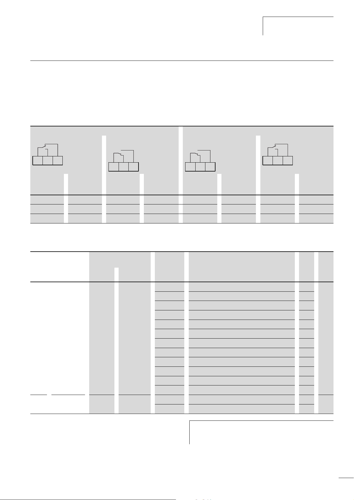
01/02 AWB8230-1413GB
efesotomasyon.com - Klockner Moeller - inverter
Programmable relay outputs K11 to K34
Programmable relay outputs
K11 to K34
Signalling relay terminals K11, K12, K14
If a fault occurs, the signalling relay (changeover) is triggered. The
switching conditions can be programmed as required.
Table 18: Default setting of the signalling relay
Default setting of the signalling relay Reconfigured signalling relay terminals (PNU C036 = 00)
Fault or DF6 switched off Run signal Fault message Run signal or DF6 switched off
K12K11 K14
K12K11 K14 K12K11 K14
Voltage Operating
state
On Normal Open Closed On Normal Closed Open
On Fault Closed Open On Fault Open Closed
Off – Closed Open Off – Closed Open
X Under PNU C026, enter the type of signalling. X Use the above table to configure contact K11-K12 or K11-K14
K11-K12 K11-K14 Voltage Operating
By default, the signalling relay output is used for signalling faults,
but you can also program this output normally. To do this, enter
the appropriate value in PNU C026 (the default value, 05, means
that the output is used for fault signalling).
K12K11 K14
K11-K12 K11-K14
state
as make or break contacts under PNU C036.
PNU Name Adjustable in RUN mode Value Function Page WE
Normal Extended
C026 Signal at
signalling relay
output
C036 Signalling relay
output
– j 00 RUN: Operation 96 05
01 FA1: Frequency reached signal 94
02 FA2: Frequency exceeded 94
03 OL: Overload alarm 97
04 OD: PID system deviation exceeded 98
05 AL: Fault 99
06 FA3: Frequency (within range) reached 94
08 IP: Mains failure, immediate stop 99
09 UV: Undervoltage signal 99
11 RNT: Running time exceeded 100
12 ONT: Mains On time exceeded 100
13 THM: Motor thermal overload 101
– j 00 K11-K14 close with a fault message – 01
01 K11-K14 close when the supply voltage is applied –
After a fault has occurred, the associated fault message is retained
even after the voltage supply is switched off. This fault message
can therefore be recalled from fault history register when voltage
has been switched back on. However, the inverter is reset when
the device is switched off, i.e. the fault message will not be output
at the signalling relay’s terminals after the inverter is switched
back on.
If however, the fault signal is to be retained even after the
h
inverter is switched back on, a latching (self maintaining)
relay should be used.
93
Page 97
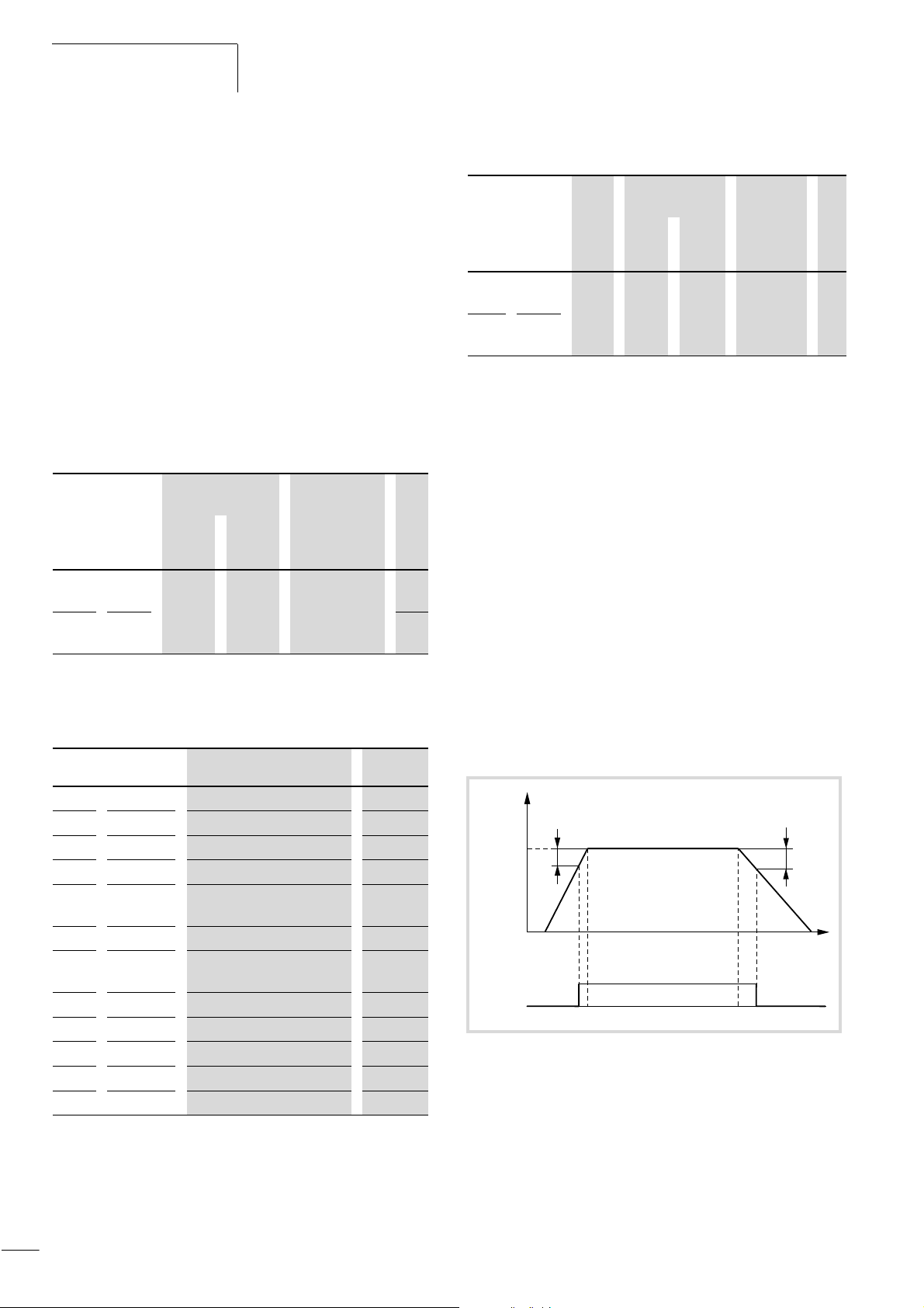
Programming the Control
efesotomasyon.com - Klockner Moeller - inverter
Signal Terminals
01/02 AWB8230-1413GB
Note that, when the signalling relay output is configured as a
break contact (default setting), there is a delay from the time the
supply voltage is switched on until the AL output is closed, and
that a fault message for the AL output therefore appears for a
short time after the supply is switched on.
Relay outputs K23-K24 and K33-K34
The same functions can be assigned to the two relay outputs as to
the signalling relay.
The terminal functions for programmable digital relay outputs
K23-K24 and K33-K34 are configured under PNU C021 and C022
respectively, i.e. PNU C021 defines the function of relay output
K23-K24, PNU C022 the function of relay output K33-K34.
Table 19: Relay outputs K23-K24 and K33-K34
PNU Ter-
minal
C021 K23-
K24
C022 K33-
K34
Adjustable in
RUN mode
Normal Exten-
ded
– j a table 2 01
Value WE
00
For a detailed description of the output functions, see the pages
listed in table 20.
Table 20: Functions of the relay outputs
Value Function Description a page
Table 21: Configuring relay outputs as make contacts
PNU Ter-
minal
C031 K23-
K24
C032 K33-
K34
Value Adjustable in
RUN mode
Nor-
mal
00 or 01– j 00: Make
Extended
Function WE
contact
01: Break
contact
00
Frequency arrival signal (FA1/FA2/FA3)
The digital output configured as FA1 is activated as soon as the
setpoint frequency is reached (a fig. 87).
The digital output configured as FA2 is active while the
frequencies defined under PNU C042 and C043 are exceeded
(a fig. 89).
The digital output configured as FA3 is activated when the
frequency defined under PNU C042 is reached during acceleration.
As soon as this frequency is left, FA3 is deactivated again. During
deceleration, FA3 responds in the same way at the frequency set
under PNU C043 (a fig. 90).
To achieve a certain hysteresis, signals FA1 to FA3 are each
activated with f
deactivated again with f
are:
and f
2
• f
: 1 % of the end frequency (PNU A004, A204)
1
before the switching threshold is reached and
1
on leaving the switching threshold. f1
2
• f2: 2 % of the end frequency (PNU A004, A204)
00 RUN Operation 96
01 FA1
02 FA2
03 OL
04 OD
05 AL
06 FA3
08 IP
09 UV
11 RNT
12 ONT
13 THM
Frequency setpoint reached 94
Frequency exceeded 94
Overload signal 97
PID control deviation
exceeded
Fault 99
Frequency (within range)
reached
Mains failure, immediate stop 99
Undervoltage signal 99
Running time exceeded 100
Mains On time exceeded 100
Motor thermal overload 101
98
94
Programmable relay outputs K23-K24 and K33-K34 are, by
default, configured as make (NO) contacts.
If required, you can also configure the relay outputs as break (NC)
contacts. To do this, enter 01 under PNU C031 and C032
(corresponding to relay outputs K23-K24 and K33-K34).
f
O
PNU F001
Figure 87: Function chart for FA1 (frequency reached)
f
: Output frequency
o
: 1 % of the end frequency (PNU A004, A204)
f
1
: 2 % of the end frequency (PNU A004, A204)
f
2
F001: Setpoint
FA1
f
1
f
2
t
94
Page 98
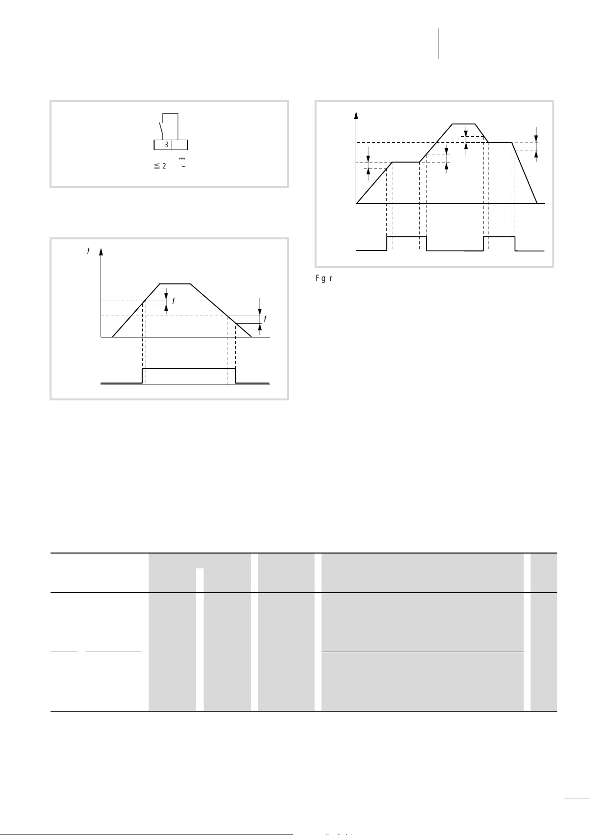
01/02 AWB8230-1413GB
efesotomasyon.com - Klockner Moeller - inverter
Programmable relay outputs
K11 to K34
FA1/
FA2/
FA3
K23 K24
5...30 V
0
.
250 V
D
Figure 88: Relay output K23-K24 configured as FA1/FA2/FA3
(frequency reached/exceeded)
B
O
PNU C042
PNU C043
FA2
B
1
Figure 89: Function chart for FA2 (frequency exceeded)
fo:Output frequency
: 1 % of the end frequency (PNU A004, A204)
f
1
2 % of the end frequency (PNU A004, A204)
f
2:
f
O
f
PNU C043
PNU C042
FA3
f
1
1
f
2
f
2
Figure 90: Function chart for FA3 (frequency reached)
: Output frequency
f
o
: 1 % of the end frequency (PNU A004, A204)
f
1
: 2 % of the end frequency (PNU A004, A204)
B
2
f
2
X If you configure a programmable relay output as FA2, you must
also, under PNU C042, enter the frequency from which the FA2
signal is active during acceleration.
X With PNU C0043, set the respective frequency which is to
remain active until the FA2 signal is deactivated during
deceleration.
X Do the same for FA3.
X Program one of the relay outputs K23-K24 or K33-K34 as FA1
to FA3 output by entering one of the following values in the
corresponding PNU (C021 or C022) or in PNU C026 for
signalling relay contacts K11-K12:
–FA1: 01
–FA2: 02
–FA3: 06
By default, FA1 is assigned to relay output K23-K24.
PNU Name Adjustable in RUN mode Value Function WE
Normal Extended
C042 Frequency
switching
threshold
during
acceleration
C043 Frequency
switching
threshold
during
deceleration
– j 0 to 400 Hz The relay output configured as FA2 or FA3 (K11-K12,
K23-K24, K33-K34) is activated when the frequency entered
here is exceeded.
The relay output configured as FA2 or FA3 (K11-K12,
K23-K24, K33-K34) remains active, as long as the frequency
entered here is exceeded during deceleration (a fig. 89
and fig. 90).
0.0
95
Page 99
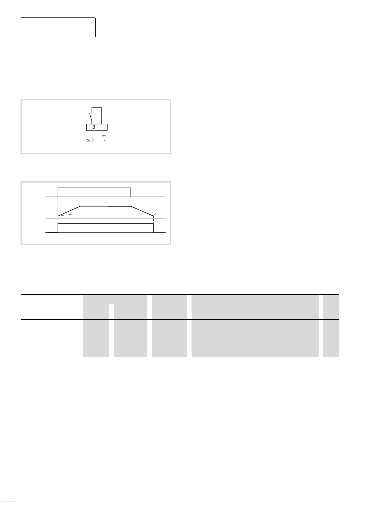
Programming the Control
efesotomasyon.com - Klockner Moeller - inverter
Signal Terminals
01/02 AWB8230-1413GB
Run signal (RUN)
The relay output configured as RUN remains activated as long as
a frequency not equal to 0 Hz is present, i.e. as long as the motor
is driven in a clockwise or anticlockwise direction.
RUN
K33 K34
5...30 V
0
.
250 V
D
Figure 91: Relay output K23-K24 configured as RUN (Run signal)
FWD/REV
a
a
RUN
f
O
X Program one of the relay outputs K23-K24 or K33-K34 as RUN
output by entering the value 00 in the corresponding PNU
(C021 or C022) or in PNU C026 for signalling relay contacts
K11-K12.
By default, RUN is assigned to relay output K33-K34.
Figure 92: Function chart for RUN (Run signal)
: Output frequency
f
o
a Starting frequency defined with PNU b082
PNU Name Adjustable in RUN mode Value Function WE
Normal Extended
b082 Increased
starting
frequency
– j 0.5 to 9.9 Hz A higher starting frequency results in shorter acceleration
and deceleration times (for example to overcome high
frictional resistance). If the frequencies are too high, fault
message E02 may be issued. Up to the set starting
frequency, the motor accelerates without a ramp function.
0.5
96
Page 100
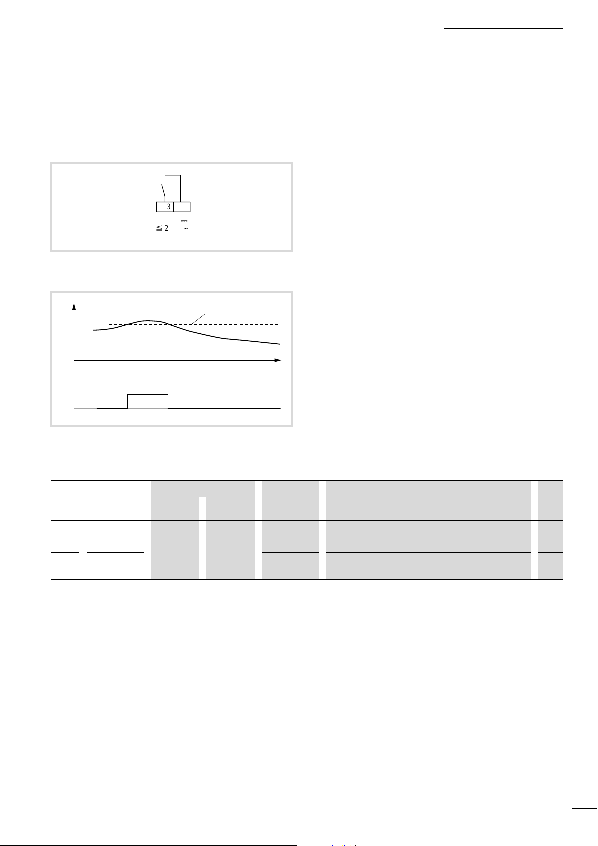
01/02 AWB8230-1413GB
efesotomasyon.com - Klockner Moeller - inverter
Programmable relay outputs
K11 to K34
Overload signal (OL)
The relay output configured as OL is activated when a freely
selectable motor current is exceeded. The OL output is active as
long as the motor current is higher than this threshold.
OL
K23 K24
5...30 V
0
.
250 V
D
Figure 93: Relay output K23-K24 configured as OL (overload signal)
r
I
M
OL
PNU C041
X To configure a programmable relay output as OL, define the
current under PNU C041 at which, when exceeded, the OL
signal is activated.
X Then, program one of the relay outputs K23-K24 or K33-K34 as
OL output by entering the value 03 under PNU C021 or C022 or
in PNU C026 for signalling relay contacts K11K12.
Figure 94: Function chart for OL (overload signal)
: Motor current
I
M
PNU Name Adjustable in RUN mode Value Function WE
Normal Extended
C040 Overload alarm
signal
C041 Overload alarm
threshold
– j 00 Always 01
01 Only at constant speed
0 to 2 x I
1)
The current value entered here determines when the OL
e
overload signal should be activated.
1) Frequency inverter rated current
1)
I
e
97
 Loading...