

Page 1

6-Channel Remote Control System
"MC60"
Item no.: 20 72 56
Operating instructions
Version 04/10
Page 2

Table of Contents
1. Introduction ........................................................................................................................................................... 4
2. Intended Use ......................................................................................................................................................... 4
3. Product Description ............................................................................................................................................... 5
4. Scope of Delivery .................................................................................................................................................. 5
5. Symbols................................................................................................................................................................. 5
6. Safety Information ................................................................................................................................................. 6
a) General Information ......................................................................................................................................... 6
b) Operation .......................................................................................................................................................... 7
7. Notes on Batteries and Rechargeable Batteries .................................................................................................. 8
8. Charging Rechargeable Batteries ........................................................................................................................ 9
9. Transmitter Controls............................................................................................................................................ 10
a) Front ............................................................................................................................................................... 10
b) Rear ................................................................................................................................................................ 11
10. Setting up the Transmitter ................................................................................................................................... 12
a) Inserting the Batteries/Rechargeable Batteries ............................................................................................. 12
b) Charging the Rechargeable Transmitter Batteries ......................................................................................... 13
c) Switching on the Transmitter .......................................................................................................................... 14
d) Modifying the Throttle Function ...................................................................................................................... 15
e) Setting the Control Levers .............................................................................................................................. 16
11. Setting up the Receiver ....................................................................................................................................... 16
a) Receiver Connection ...................................................................................................................................... 16
b) Installing the Receiver .................................................................................................................................... 18
c) Installing the Servos ........................................................................................................................................19
d) Checking the Servo Functions ....................................................................................................................... 19
12. Programming the Remote Control ...................................................................................................................... 20
13. The System Menu ............................................................................................................................................... 21
13.1. “MODELSET” (Model Settings) ................................................................................................................. 22
a) “MODEL” (Selection of the Model Memory) .............................................................................................. 22
b) “RENAME” (Model Memory Name)........................................................................................................... 23
c) “SAVE AS” (Copy a Model Memory) ......................................................................................................... 24
d) “RECOVER” (Resetting to the Factory Settings) ...................................................................................... 25
13.2. “MODULATE” (Setting the Transmitter Modulation) ................................................................................. 26
13.3. “PLANE TYPE” (Setting the plane type) ................................................................................................... 27
13.4. “STICK MODE” (Transmitter Lever Settings) ............................................................................................ 28
13.5. “STICK ADJ” (Control Lever Calibration) .................................................................................................. 30
Page
2
Page 3

Page
14. Function Menu .................................................................................................................................................... 31
14.1. “DR” (Servo Path Limiter)........................................................................................................................ 32
14.2. “SUB.TRIM” (Servo Centre Position) ...................................................................................................... 35
14.3. “TRAVEL” (Servo Travel Settings) .......................................................................................................... 36
14.4. “CH.REV” (Reversing the Servo Direction) ............................................................................................ 37
14.5. “SWASH.MIX” (Swash Plate Mixer) ........................................................................................................ 38
14.6. “GYRO.SENS” (Gyro Sensitivity) ............................................................................................................ 40
14.7. “THRO.CURV” (Throttle Curve) .............................................................................................................. 42
14.8. “MONITOR” (Servo Path Display)........................................................................................................... 44
14.9. “PIT.CURV” (Pitch Curve) ....................................................................................................................... 45
14.10. “THRO.HOLD” (Throttle Hold Function) ................................................................................................. 48
14.11. “V-TAIL” (V-Tail Mixer) ............................................................................................................................. 49
14.12. “DELTA MIX” (Delta Mixer)...................................................................................................................... 51
15. Remote Control Operation .................................................................................................................................. 54
16. Crystal Change ................................................................................................................................................... 55
17. Maintenance and Care ....................................................................................................................................... 55
18. Disposal ............................................................................................................................................................... 56
a) General Information ........................................................................................................................................ 56
b) Batteries and Rechargeable Batteries ........................................................................................................... 56
19. Troubleshooting .................................................................................................................................................. 57
20. Technical Data ..................................................................................................................................................... 58
a) Transmitter...................................................................................................................................................... 58
b) Receiver ......................................................................................................................................................... 58
21. Declaration of Conformity (DOC) ........................................................................................................................ 58
3
Page 4

1. Introduction
Dear Customer,
Thank you for purchasing this product.
The product meets the requirements of the current European and national guidelines.
To maintain this status and to ensure safe operation, you as the user must observe these operating instructions!
These operating instructions are part of this product. They contain important information concerning operation and handling. Please bear this in mind in case you pass on the product to any
third party.
Therefore, keep these operating instructions for future reference!
All company names and product names are trademarks of the respective owners. All rights reserved.
In case of any technical inquiries, contact or consult:
2. Intended Use
The remote control is solely designed for private use in the field of model construction and the operating times associated with it. This system is not suitable for industrial use, such as controlling machines or equipment.
Tel. no.: +49 9604 / 40 88 80
Fax. no.: +49 9604 / 40 88 48
E-mail: tkb@conrad.de
Mon. to Thur. 8.00am to 4.30pm, Fri. 8.00am to 2.00pm
Any use other than the one described above damages the product. Moreover, this involves dangers such
as short-circuit, fire, electric shock, etc.
The remote control must not be technically modified or rebuilt!
Observe all safety notes in these operating instructions. They contain important information regarding the
handling of the product.
You are solely responsible for the safe operation of your remote control and your model!
4
Page 5

3. Product Description
The “MC60” remote control system is a radio remote control system ideally suited for model motor planes, model
gliders or model helicopters.
The proportional channels allow you to use the steering function and control function independently from each other.
The remote control also features several mixing and memory functions needed for the different models. The settings
of up to 6 different models can be saved in the remote control system.
The display is easily readable and the easy-to-use buttons allow you to easily, quickly and safely enter data. Thanks to
electronic trimming, the rudders are always in the correct position. The last set position is assumed automatically when
the remote control is switched on!
The ergonomic casing can be held and operated comfortably and allows you to safely control the model.
For operating, 8 mignon batteries (e.g. Conrad item no.: 652507, pack of 4, order 2) or rechargeable batteries are
needed. The receiver requires 4 AA batteries (e.g. Conrad item no.: 652507, pack of 4, order 1) or rechargeable
batteries.
4. Scope of Delivery
• Transmitter
• Receiver
• Operating instructions
5. Explanation of Symbols
The symbol with the exclamation mark points out particular dangers associated with handling, function or
operation.
The “arrow” symbol indicates special advice and operating information.
5
Page 6

6. Safety Information
In case of damage caused by non-compliance with these safety instructions the warranty / guarantee will become void. We do not assume any responsibility for consequential damage!
We do not assume any liability for damage to property or personal injury caused by improper use
or the failure to observe the safety instructions! In such cases the warranty/guarantee is void.
Normal wear and tear in operation and damage due to accidents (like the receiver aerial being torn
off, the receiver housing broken etc.) are excluded from the warranty.
Dear Customer, these safety instructions are not only for the protection of the product but also for your own safety and
that of other people. Therefore, read this chapter very carefully before putting the product into operation!
a) General Information
Caution, important note!
Operating the model may cause damage to property and/or individuals.
Therefore, make sure that you are properly insured when using the model, e.g. by taking out private
liability insurance. If you already have private liability insurance, inquire about whether the operation of the
model is covered before operating it.
• The unauthorized conversion and/or modification of the product is prohibited for safety and approval reasons (CE).
• The product is not a toy and should be kept out of reach of children under 14 years of age.
• The product must not become damp or wet.
• Do not leave packaging material unattended. It may become a dangerous toy for children.
• Do not connect the drive motor to electric models before the receiver system has been installed completely. This
ensures that the drive motor does not start unintentionally.
• Please check the functional safety of your model and of the remote control system each time before you use the
model. Watch out for visible damage such as defective plug connections or damaged cables. All movable parts on
the model have to be running smoothly. However, there must be no tolerance or ‘play’ in the bearing.
• Should questions arise that are not answered with the help of this operating manual, contact us (contact information,
see chapter 1) or another expert.
• The operation and handling of RC models must be learned! If you have never controlled such a model, start especially carefully to get used to how it responds to the remote commands. Do be patient!
6
Page 7

b) Operation
• If you do not yet have sufficient knowledge on how to deal with remote-controlled models, please contact an experienced model sportsman or a model construction club.
• Each time before you use the product, make sure that there are no other models operated within the same range of
frequency or channel as your own remote control. Control over remote controlled vehicles will be lost! Always use
different frequencies/channels.
• When putting the device into operation, always turn on the transmitter first. Then switch on the receiver in the model.
Otherwise, the model might show unpredictable responses! Always pull out the telescopic aerial of the remote
control completely.
• Before operating the model, check whether the stationary model reacts to the commands of the remote control as
expected.
• When you operate the model, always make sure that no parts of your body, other people or objects come within the
dangerous range of the motors or any other rotating drive parts.
• Improper operation can cause serious damage to people and property! Always make sure that the model is in direct
visual contact and do not operate it at night.
• Do not operate your model if your ability to respond is unrestricted. Fatigue or the influence of alcohol or medication
can lead to wrong responses.
• Operate your model in an area where you do not endanger other people, animals or objects. Only operate it on
private sites or in places which are specifically designated for this purpose.
• In case of an error, stop operating your model straight away and remove the cause of malfunction before you
continue to use the model.
• Do not operate your RC system during thunderstorms, under high-voltage power lines or in the proximity of radio
masts.
• Never switch off the remote control (transmitter) while the model is in use. To switch off the model, always switch off
the motor first, then switch off the receiver. Only then may the remote control be switched off.
• Protect the remote control from dampness and heavy dirt.
• Do not expose the remote control to direct sunlight or excessive heat for a long period of time.
• If the batteries (or rechargeable batteries) in the remote control are low the range decreases. If the rechargeable
battery in the receiver is low, the model will not respond correctly to the remote control.
If this is the case, stop flying immediately. Replace the batteries with new ones or recharge the rechargeable batteries.
• Do not take any risks when operating the product! Your own safety and that of your environment depends completely
on your responsible use of the model.
7
Page 8

7. Notes on Batteries and Rechargeable Batteries
• Keep batteries/rechargeable batteries out of the reach of children.
• Do not leave any batteries/rechargeable batteries lying around openly. There is a risk of batteries being swallowed
by children or pets. If swallowed, consult a doctor immediately!
• Batteries/rechargeable batteries must never be short-circuited, disassembled or thrown into fire. There is a danger
of explosion!
• Leaking or damaged batteries/rechargeable batteries may cause acid burns when coming into contact with skin.
Use suitable protective gloves.
• Do not recharge normal batteries. There is a risk of fire and explosion! Only charge rechargeable batteries intended
for this purpose. Use suitable battery chargers.
• Please observe correct polarity (positive/+ and negative/-) when inserting the batteries/rechargeable batteries.
• If the device is not used for a longer period of time (e.g. storage), take out the inserted batteries/rechargeable
batteries inserted in the remote control and in the car to avoid damage from leaking batteries/rechargeable batteries.
Recharge the rechargeable batteries about every 3 months, because otherwise there may be a total discharge due
to self-discharge, which makes the rechargeable batteries useless.
• Always replace the entire set of batteries or rechargeable batteries. Never mix fully charged batteries/rechargeable
batteries with partially discharged ones. Always use batteries or rechargeable batteries of the same type and manufacturer.
• Never mix batteries and rechargeable batteries! Either use batteries or rechargeable batteries for the remote control.
The remote control (transmitter) may be operated with rechargeable batteries instead of batteries.
However, the lower voltage (batteries=1.5 V, rechargeable batteries=1.2 V) and the lower capacity of
rechargeable batteries do lead to a decrease of the operating time. Normally this does not matter, since
the operating time of the remote control exceeds that of the model.
If you use batteries in the remote control, we recommend the use of high-quality alkaline batteries.
When rechargeable batteries are used, the range can be reduced.
8
Page 9

8. Charging Rechargeable Batteries
The rechargeable mignon batteries required for the RC system are, in general, empty on delivery and must be charged.
Please note:
Before a rechargeable battery reaches maximum capacity, several complete discharge and charge cycles
are necessary.
Always discharge the rechargeable battery at regular intervals, since charging a “half-full” rechargeable
battery several times can cause a so-called memory effect. This means that the rechargeable battery
loses its capacity. It no longer provides all of its stored energy, and the operating time of the model and the
remote control is reduced.
If you use several rechargeable batteries, purchasing a high-quality charger may be worthwhile. Such a
charger usually has a quick-charging feature.
9
Page 10
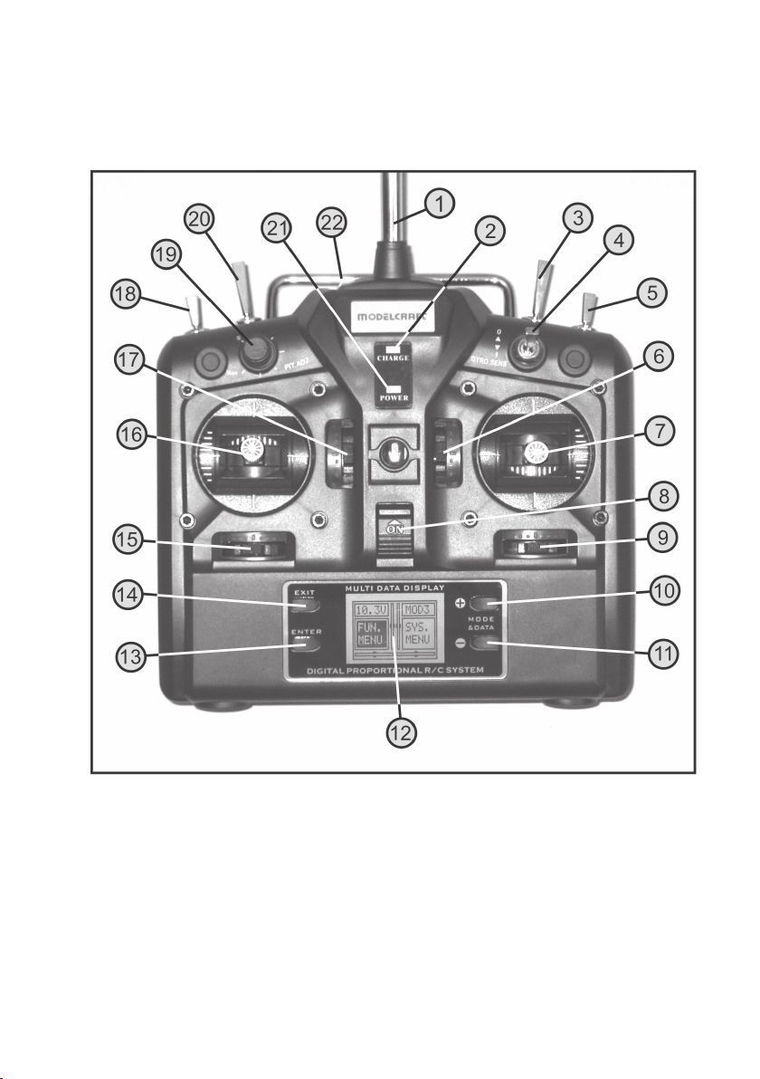
9. Transmitter Controls
a) Front
10
Figure 1
Page 11
1. Transmitter aerial
2. Charge volume indication
3. “AILE D/R” toggle switch
4. “GYRO.SENS” toggle switch
5. “TH.HOLD” toggle switch
6. Trim button for elevator/nod function (in mode II)*
7. Control lever for elevator/nod and aileron/roll function (in mode II)*
8. Function switch
9. Trim button for aileron/roll function (in mode II)*
10. “+” (plus) button
11. “-” (minus) button
12. Multi-functional display
13. “Enter” button
14. “Exit” button
15. Trim button for rudder/tail function (in mode II)*
16. Control lever for rudder/tail and throttle/pitch function (in mode II)*
17. Trim button for throttle/pitch function (in mode II)*
18. “IDLE” toggle switch
19. “PIT.ADJ.” rotary control
20. “ELEV.D/R” toggle switch
21. Operational charge display
22. Carrying handle
* For further information on this, see the chapter “Programming the remote control transmitter” in the “Sytem Menu”
section and the sub-section “STICK MODE”.
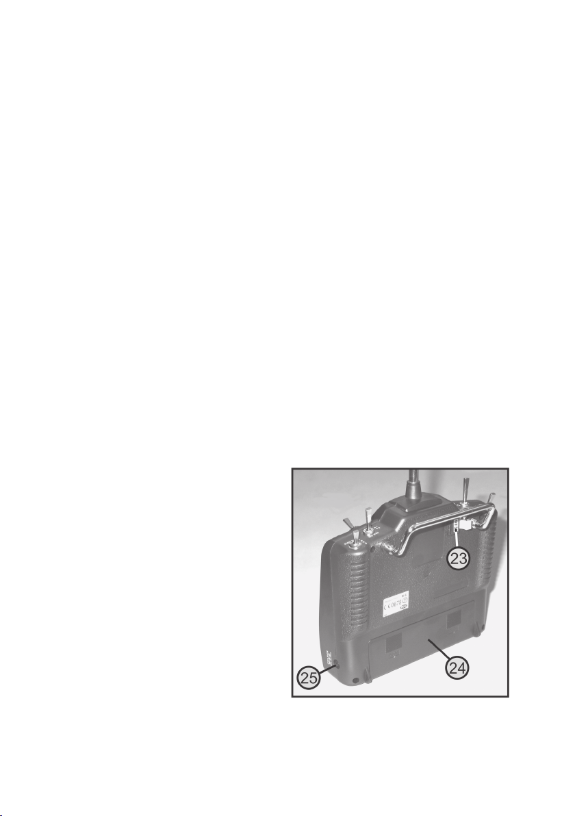
b) Back
23. Transmitter crystal
24. Battery compartment lid
25. Charging jack
Figure 2
11
Page 12
10. Setting up the Transmitter
Important note:
In the operating instructions, the numbers in the text always refer to the figure opposite or the figures within
the section. Cross-references to other figures will be indicated by the corresponding figure number.
a) Inserting the Batteries/Rechargeable Batteries
The power supply of the transmitter requires 8 alkaline batteries (e.g. Conrad Item No.: 652507, pack of 4, order 2) or
rechargeable batteries. For ecological and also for economical reasons it is recommended to use rechargeable batteries, since they can be recharged in the transmitter via a built-in charging socket (see fig. 2 pos. 25).
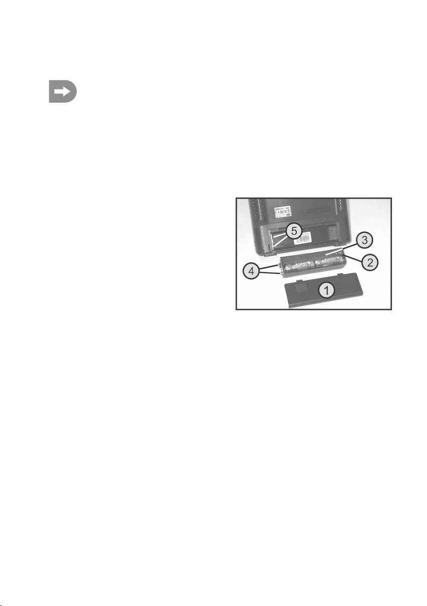
To insert the batteries or rechargeable batteries, please proceed as follows:
The battery compartment lid (1) is located on the back of the
transmitter. Press the two corrugated areas and push off the
lid downwards.
Remove the battery holder (2) and place 8 batteries or 8 rechargeable batteries in the battery compartment.
Always make sure the polarity of the batteries is correct. A
corresponding label (3) is located at the bottom of the battery
compartment.
When inserting the filled battery case, ensure that the two
connections of the case (4) have good contact to the coach
springs in the transmitter (5).
Then slide the cover of the battery compartment back on and
let it snap into place.
Figure 3
12
Page 13
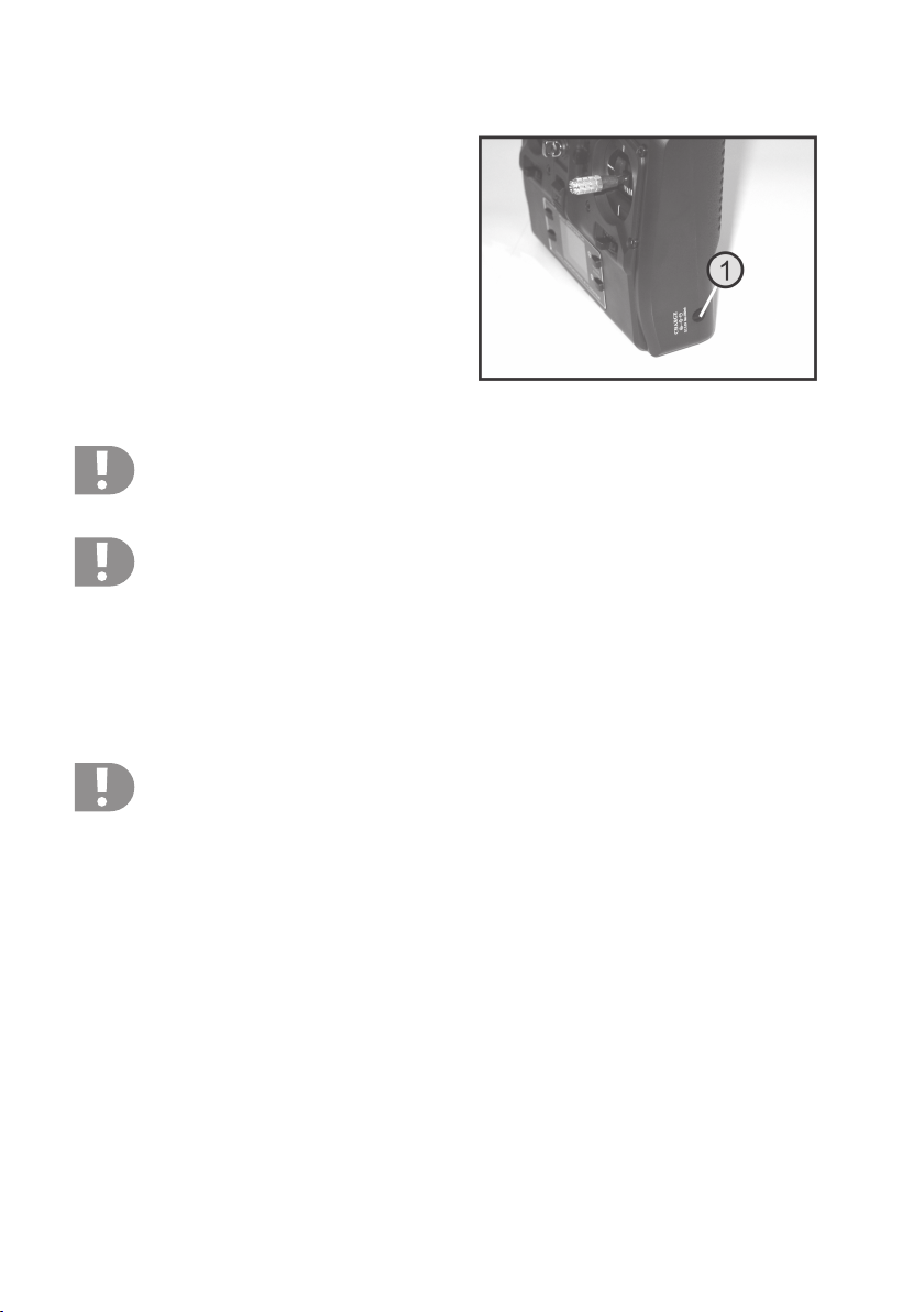
b) Charging the Rechargeable Transmitter Batteries
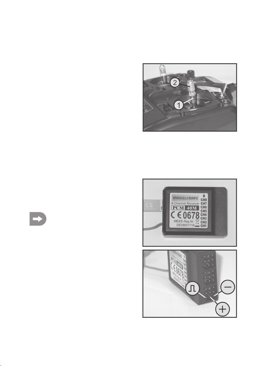
The charging socket (1) is located on the right side of the transmitter. When rechargeable batteries are inserted, you can
connect the charger cable to charge the rechargeable batteries in the transmitter.
Always make sure the polarity of the connecting plug is correct. The inner contact of the charging socket must be connected to the positive terminal (+) and the outer contact to the
negative terminal (-) of the charger.
The charging current should correspond to approximately 1/
10 of the capacity value of the inserted rechargeable batteries. For rechargeable batteries with a capacity of 2000 mAh,
this corresponds to a charging current of approx. 200 mA and
charging time takes approx. 14 h.
Attention!
Before charging the rechargeable batteries in the transmitter, remove the transmitter crystal from the back
of the transmitter (see fig. 2, pos. 23). Otherwise, charging is not possible.
Caution!
Connect the charger only if rechargeable batteries (1.2V/cell) have been inserted in the transmitter. Never
try to recharge normal batteries (1.5V/cell) with a charger. There is a risk of fire and explosion!
During charging, the operating display appears (see fig. 1, item 12) and the operating voltage (see fig. 1, item 21)
lights up. Additionally, the flashing charging control lamp (see fig. 1, item 2) indicates that the batteries are being
charged. When the rechargeable batteries are fully charged and the charge end voltage was reached, the charge
control lamp goes out.
After the charger is separated from the transmitter, you can push the transmitter crystal back into the casing and check
the system’s function.
Attention!
In order to avoid damage to the internal conductor paths and connections, please do not use any quick
chargers. Charging current should not exceed 200 mA.
As an alternative to charging the rechargeable batteries right in the transmitter, mignon rechargeable batteries can
also be taken from the remote control and charged in a suitable round cell charger.
Figure 4
13
Page 14
c) Switching on the Transmitter
When the rechargeable batteries are fully charged or new batteries have been inserted, completely pull out the remote
control aerial (see fig. 1, pos. 1).
Check the position of the toggle switches. All switches should be in the forward or bottom positions (switch position “0”
or “N”). Now switch on the transmitter using the “on/off” switch (see fig. 1, pos. 8).
The operating voltage indication (see fig. 1, pos. 21) indicates that the transmitter is sufficiently supplied with power.
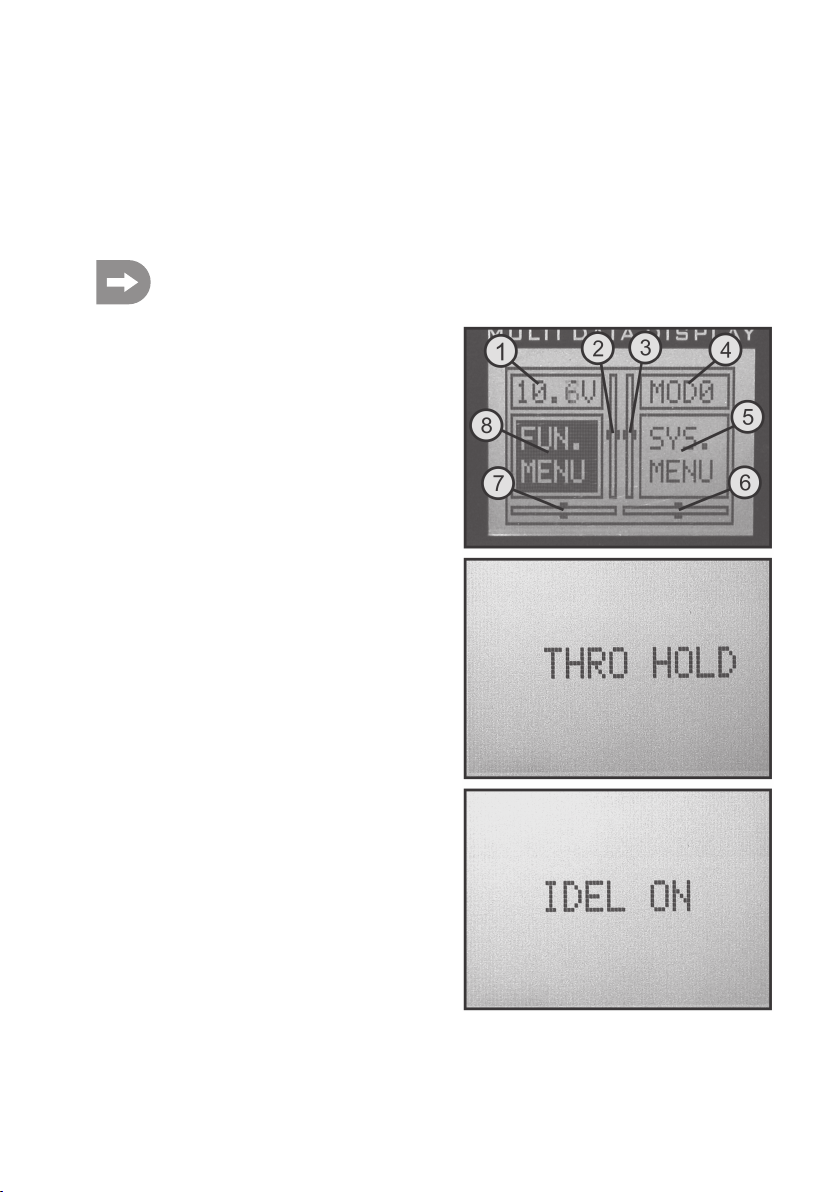
Additionally, an acoustic signal sounds and the display shows the operating display (see figure 5).
If the “TH.HOLD” switch (see figure 1, pos. 5) or the “IDLE” switch (see figure 1, pos. 18) are not in the front
or lower position, a quick series of acoustic signals sounds and the respective switch is indicated in the
display (see fig. 5).
When the switch is put in the correct position, the alarm is
switched off and the operating display goes out.
The operating display consists of the following elements:
1. Operating voltage display
2. Throttle/pitch trimming display (in Mode II)*
3. Elevator/nod trimming display (in Mode II)*
4. Memory display
5. System menu display
6. Aileron/roll trimming display (in Mode II)*
7. Rudder/tail trimming display (in Mode II)*
8. Function menu display
* For further information on this, see chapter “Programming
the Remote Control Transmitter”, section “Sytem Menu”
and sub-section “STICK MODE”.
The respective menu that can be called (function or system
menu) is highlighted with a dark background. To switch between the two menus, press the button “+” (see fig. 1, pos.
10) or the button “-”(see fig. 1, pos. 11). The remote control
emits a signal tone for each press of a button.
If the power supply is not sufficient for faultless operation any
more (at a voltage of less than 8.5 V), a repeating signal tone
and flashing operating voltage display (see fig. 1 item 21) indicates the lack of sufficient battery power.
In this case, you should stop operating your model as quickly
as possible. To continue operating the transmitter, recharge
the batteries or insert new batteries.
14
Figure 5
Page 15
d) Modifying the Throttle Function
If you prefer to have the throttle function on the right instead of the left hand lever, you have the option of swapping the
rest/hold function and the spring return mechanism of the two lever units.
To make the necessary changes, some experience with remote control transmitters is required. Therefore you should
consult an experienced model maker or a model construction club if you do not feel capable of undertaking the
procedures described in the following.
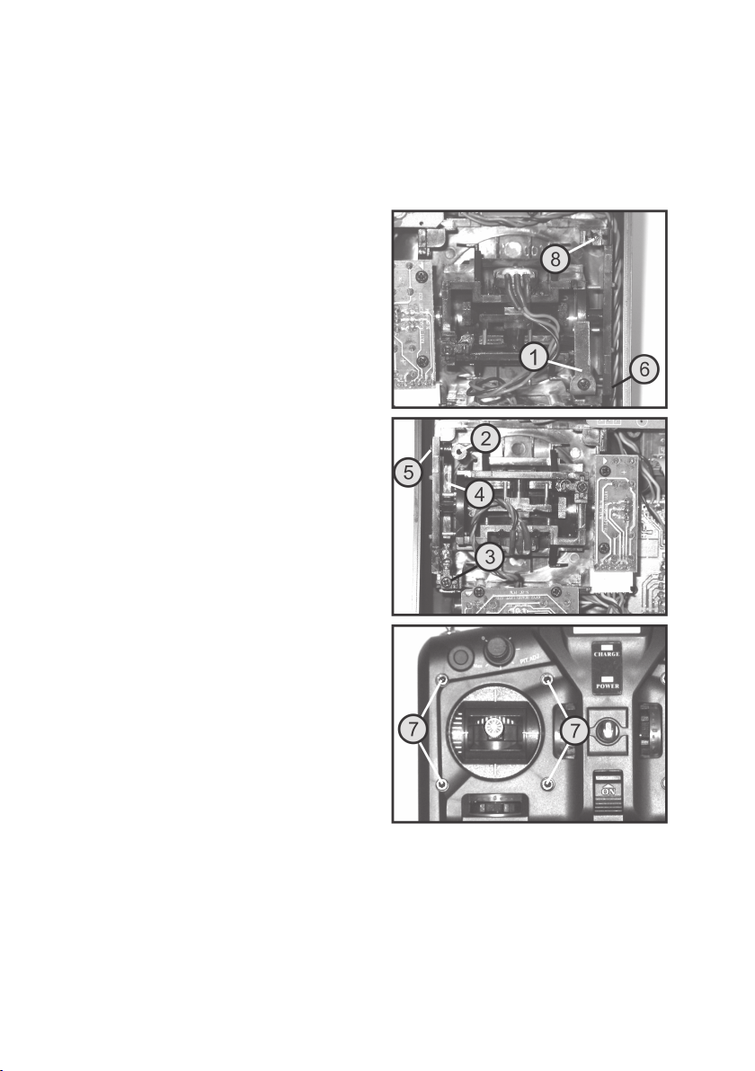
Unscrew the four screws by means of a Phillips-tip screwdriver from the rear panel of the transmitter and lift the rear
panel carefully.
Remove the coach spring (1) from the right lever aggregate
(seen from the rear) and screw it on to the left aggregate’s
spring at the prepared screw hole (2).
Turn the adjustment screw for the lever return force (3) at the
left lever aggregate (seen from the rear) out with a suitable
screw driver until the return spring is completely relieved.
Bend the tip of a pin with fine tongs to form a hook and use it
to unhook the return spring from the adjustment screw hook.
The return spring and adjustment screw can now be removed.
To be able to remove the return lever (4) as well, the retaining
screw (5) must be removed.
To be able to install the return lever reversed mirror-inverted
in the right lever aggregate (seen from the rear), the retaining
screw (5) must be screwed into the prepared bore (6). Remove the four retaining screws (7) of the lever aggregate at
the front of the transmitter and lift it out of the casing until you
can turn in the screw, since the transmitter side is in the way
otherwise. Then, the lever aggregate is attached again.
After hooking the return spring into the return lever, push the
adjusting screw into the prepared bore (8) and attach the return spring to the hook of the adjustment screw.
Then you can check the mechanical function of the lever aggregate and set the desired return force of the control lever.
Figure 6
When attaching the back, ensure that no cables are squeezed and screw on the transmitter’s back cover again. The
electronic modification of the throttle function is done later in the system menu under “STICK MODE”.
15
Page 16
e) Setting the Control Levers
As already shown in section “Modifying the Throttle Function”, the return forces for the control levers can be set
individually. For this, each of the three return springs has a separate adjustment screw (also see figure 5, pos. 3).
When the screw is turned in, the return force is lowered. If the adjustment screw is screwed out, the restoring force is
increased. The control lever length can also be adjusted.
To do so simply hold the bottom part of the grip (1) and turn
the upper part (2) anti-clockwise. You can now set the length
of the control lever by turning the bottom part of the grip.
Finally, tighten the upper part of the grip back up.
Figure 7
11. Setting up the Receiver
a) Receiver Connection
On its right hand side the receiver offers the option of connecting up to 8 servos with Futaba or JR plugs (CH1 to CH8).
The receiver battery is connected to connection “B”.
When connecting servos and speed or flight
controllers, always make sure to pay close attention to the correct polarity of the plug connectors.
For Futaba plug connectors protected against
polarity reversal the positive lead (yellow, white or
orange, depending on the manufacturer) must be
connected to the left of the three aligned contacts.
The plug contact for the negative line (black or
brown, depending on the manufacturer) must be
connected to the right pin contact.
16
Figure 8
Page 17

The receiver outputs are assigned as follows:
Output Helicopter Motor model plane Model glider
CH1 Roll servo Aileron servo Aileron servo
CH2 Nod servo Elevator servo Elevator servo
CH3 Throttle servo/speed controller Throttle servo/speed controller Spoiler servo
CH4 Tail servo Rudder servo Rudder servo
CH5 Gyro sensitivity Undercarriage servo * Free channel *
CH6 Pitch servo Free channel ** Free channel **
CH7 Not available Not available Not available
CH8 Not available Not available Not available
B Battery connection *** Battery connection *** Battery connection ***
* A servo connected here reacts to the rotary control “PIT.ADJ” (see figure 1, pos. 19).
** A servo connected here reacts to the toggle switch “GYRO SENS” (see figure 1, pos. 4).
*** Electric models with an electronic speed controller only require a separate rechargeable receiver battery if the
speed controller used does not have a BEC circuit. For further information, refer to the technical documents of the
controller.
Important!
It is recommended to use a pair of tweezers or long-nosed pliers to disconnect the connection. To prevent
cable breaks, you should always pull on the plastic casing of the plug to disconnect the connection. Never
pull on the cables.
17
Page 18
b) Installing the Receiver
Installation of the receiver depends on the model. For this reason, you should always follow the recommendations of
the model manufacturer regarding the installation.
With electric models, make sure to keep sufficient distance to electronic speed controllers as the speed controller can
have a negative effect on the reception quality. Regardless of the model, you should always try to install the receiver
so that it is protected from dirt, moisture, heat, and vibration in the best possible way.
Two-sided adhesive foam (servo tape) or rubber rings that hold the foam-wrapped receiver securely in place are
suitable for fastening.
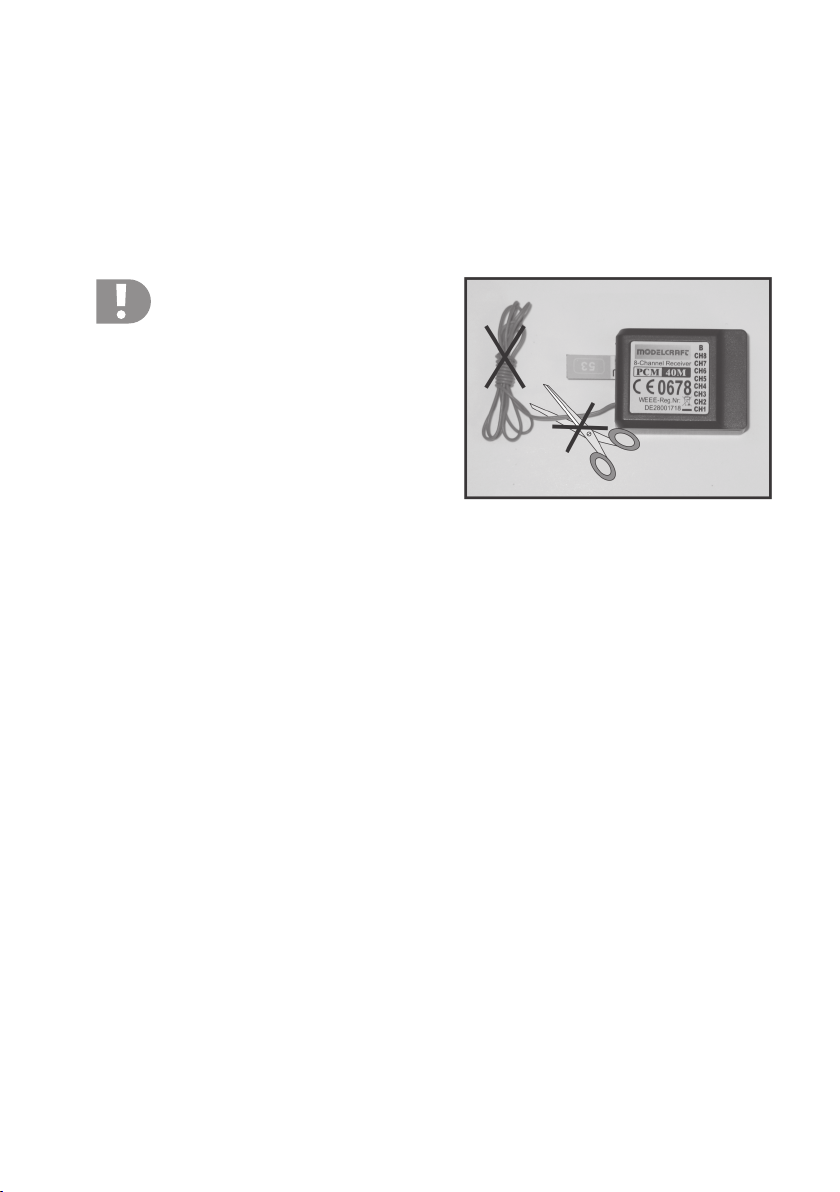
Attention!
The aerial wire has a precisely determined length.
For this reason, you must not roll up the wire, form
it into a loop or cut it off.
This would decrease the range significantly and
thus pose a considerable safety risk.
Figure 9
Pull the aerial wire out of the model through an opening in the body directly behind the receiver. To do so, you should
ideally use an aerial tube, which may be supplied with the model or which can be obtained as an accessory.
With model planes, the aerial wire can be attached to the tail, and with model helicopters, it can be attached along the
landing strut towards the tail boom.
18
Page 19

c) Installing the Servos
To install the servos (1) please use the rubber elements (2)
supplied with the servos and the screw grommet (3).
The rubber elements are intended to protect the servos from
shocks to the model during operation. Therefore, the servo
casing must be able to swing freely. It must not have direct
contact to the model.
Linkages and servo arms of servos installed next to each other
must not obstruct one another even at full deflection.
When servo arms or linkages are obstructed, the servos cannot assume the required positions. This causes higher power
consumption and the model cannot be controlled properly.
Always mount the servo lever at a 90° angle to the linkage
rods (see sketch A).
The rudder or steering travel will not be equal on both sides if
the servo lever is mounted at an angle to the linkage rod
(sketches B and C).
A slight tilt of the servo levers can later be electronically balanced out according to chapter “Programming the Remote
Control Transmitter” in the “Function Menu” section and the
sub-section “Servo Centre Position”.
2
3
A
SERVO SERVO
1
B
2
3
Figure 10
C
SERVO
Figure 11
d) Checking the Servo Functions
To run a test, connect the servos used to the receiver. Pay attention to the assignment of the receiver outputs as
described above.
Switch on the remote control, then the receiver. If attached correctly, the servos should react to movement of the
control levers at outputs 1 - 4. The servos at the outlets 5 and 6 react depending on the models programmed to the
transmitter and/or the activated switches and controllers.
Important information!
Always switch on the transmitter first, then the receiver. When you switch off the devices, always switch off
the receiver first, then the transmitter.
Never switch off the remote control as long as the receiver is in operation. This can lead to unexpected
reactions by the model!
19
Page 20

12. Programming the Remote Control
To perfectly adjust the remote control to your model, the remote control has two different menus:
1. System menu (“SYS.MENU”)
2. Function menu (“FUN.MENU”)
In the system menu, the general settings are made first and the model is selected.
In the function menu, the settings for the respective model type are then made.
Depending on the model type (helicopter or plane model) selected in the system menu, the function menu
will offer different functions.
The engine emits a short signal tone for each admissible press of a button or movement of the control
lever.
The selected menu item, the called up function or the settable value is always highlighted with a dark
background in the display.
The settings are made with the four input buttons and the
control levers. They have the following functions:
“+” button (see also fig. 1, pos. 10)
With this button, you can increase the set value or switch between menu items.
“-” button (see also fig. 1, pos. 11)
With this button, you can decrease the set value or switch
between menu items.
“ENTER” button (see also fig. 1, pos. 13)
With this button you can activate selected menu items or save
the changed settings.
“EXIT” button (see also fig. 1, pos. 14)
With this button you can exit the currently selected menu or
sub-menu without saving the changed values. Every press of
this button takes you a step back until you reach the operational display.
Figure 12
In some menus, you need to use the control lever for the rudder/tail function or the elevator/nod function to switch.
With the factory settings (Mode II)*, the left control lever reacts to left/right movement and the right one to up/down
movement.
* For further information on this, see the chapter “Programming the Remote Control Transmitter” in the “Sytem
Menu” section and the sub-section “STICK MODE”.
Important!
If you activated a different stick mode, the control levers react according to the different assignment.
20
Page 21

13. The System Menu
The following menu items are available to you in the system menu:
1. “MODEL.SET” (Model settings)
a) “MODEL” (Selection of the model memory)
b) “RENAME” (Model memory name)
c) “SAVE AS” (Copy a model memory)
d) “RECOVER” (Resetting to the factory settings)
2. “MODULATE” (Setting the transmitter modulation)
3. “PLANE TYPE” (Setting the plane type)
4. “STICK MODE” (Transmitter lever settings)
5. “STICK ADJ” (Control lever calibration)
Calling the system menu
To call the system menu, proceed as follows:
• Switch on the transmitter.
The display shows the operating display and the display for the function
menu (“FUN.MENU”) is highlighted with a dark background.
• Press button “-”.
The display changes from the function menu to the system menu
(“SYS.MENU”).
• Press “ENTER” button.
The different sub-items of the system menu are displayed and can be
switched with the “+” and “-” buttons.
Figure 13
21
Page 22

13.1. “MODEL.SET” (Model Settings)
a) “MODEL” (Selection of the Model Memory)
The remote control system has 6 model memories which allow you to save the data for your respective models
independently of one another.
Selection of the model memory
• Call the system menu and select the menu item “MODEL.SET” with the
“+” and “-” buttons.
• Activate the selected menu item with the “ENTER” button.
The display shows the model settings display. To the right of the model
memory display (“MODEL”), you can see the name of the currently active model memory (e.g. “MOD0” – “MOD5”) highlighted with a dark
background.
• Use the rudder/tail function control lever to switch between the different
model memories.
• Confirm your selection with the “ENTER” button. The data of the model
memory called is then loaded.
• Press the “EXIT” button repeatedly to exit the menu again and switch
back to the operating display. The model memory called is displayed.
22
Figure 14
Page 23

b) “RENAME” (Model Memory Name)
In order to be able to discern between model memories more easily it makes sense to give the memories the abbreviated name of the corresponding models. The name can consist of a combination of up to 4 letters or numbers.
You can only change the currently active model memory name.
Setting the model memory name
• Call the system menu and select the menu item “MODEL.SET” with the
“+” and “-” buttons.
• Activate the selected menu item with the “ENTER” button.
The display shows the model settings display. To the right of the model
memory display (“MODEL”), you can see the name of the currently active model memory (e.g. “MOD0” – “MOD5”) highlighted with a dark
background.
• Select the menu item “RENAME” with the elevator/nod function lever.
• Activate the selected menu item with the “ENTER” button.
The upper right of the display shows the name of the currently active
model memory. The first of the four name signs and the number “0” in
the numbers/letters box below it are highlighted with a dark background.
• Use the elevator/nod and the rudder/tail function levers to select the
first name abbreviation in the numbers/letters box.
• When pressing the “ENTER” button, the selected character is accepted
and the second name character is highlighted.
• Repeat the procedure until you have set all four digits of the model
memory name as desired.
• Press the “EXIT” button repeatedly to exit the menu again and switch
back to the operating display.
Figure 15
23
Page 24

c) “SAVE AS” (Copy a Model Memory)
For simple programming of the system you have the option of copying data from one model memory to another. This
helps to easily transfer basic settings between similar models and you only need to adjust the settings values to the
new model.
Important!
Before copying model data, you need to call the model memory from which the data is to be copied
(source memory).
Copying model data
• Call the system menu and select the menu item “MODEL.SET” with the
“+” and “-” buttons.
• Activate the selected menu item with the “ENTER” button.
• The display shows the model settings display. To the right of the model
memory display (“MODEL”), you can see the name of the currently active model memory (e.g. “MOD0” – “MOD5”) highlighted with a dark
background.
• Select the menu item “SAVE AS” with the elevator/nod function lever.
• Activate the selected menu item with the “ENTER” button.
The display shows the target memory display.
• Use the rudder/tail function control lever to select the desired target
memory.
• Press “ENTER” to copy the data. “SAVING” appears in the display.
• Press the “EXIT” button repeatedly to exit the menu again and switch
back to the operating display.
• Then call the model memory to which the data was copied and check
the correct servo function.
The copying function only transfers the transmitter’s setting
values. The target memory name is not changed.
24
Figure 16
Page 25

d) “RECOVER” (Resetting to Factory Settings)
With this function you have the option of deleting all the data in a model memory or even to reset all model memories
back to their factory settings.
Important!
Before resetting a model memory to factory settings, you need to call the respective model memory.
Resetting to the factory settings
• Call the system menu and select the menu item “MODEL.SET” with the
“+” and “-” buttons.
• Activate the selected menu item with the “ENTER” button.
The display shows the model settings display. To the right of the model
memory display (“MODEL”), you can see the name of the currently active model memory (e.g. “MOD0” – “MOD5”) highlighted with a dark
background.
• Select the menu item “RECOVER” with the elevator/nod function lever.
• Activate the selected menu item with the “ENTER” button.
The display for resetting the model memory appears.
• Press the “EXIT” button repeatedly to exit the menu again and switch
back to the operating display.
When resetting, only the setting values of the memory are set
to the factory parameters. The model memory name is not
changed.
Figure 17
25
Page 26

13.2. “MODULATE” (Setting the Transmitter Modulation)
The position of the individual control sticks, controls and switches is read by the transmitter. The corresponding resistance values are converted to electric pulses. The electric pulses of all control elements are transmitted one after
another to the high-frequency element as a pulse sequence.
The positive pulses always have the same width. The control information is in the pauses between the individual
pulses. Depending on the position of the control stick, the pauses become longer or shorter. The technical term for this
procedure is also known as pulse pause modulation or pulse position modulation (PPM).
The pulse code modulation (PCM) digitalises signals and routes them to the RF stage as a coded data signal.
Important!
The modulation type set on the transmitter depends on the receiver used. A PPM receiver can only be
controlled by a PPM-modulated transmitter signal. A PCM receiver requires a PCM transmitter signal.
As opposed to PCM transmission, which generally only works with components of the same manufacturer,
PPM transmission allows you to use receivers of different manufacturers.
Setting the modulation
• Call the system menu and select the menu item “MODULATE” with the
“+” and “-” buttons.
• Activate the selected menu item with the “ENTER” button.
The display shows the model settings display. The currently active modu-
lation type is highlighted with a dark background.
• Use the rudder/tail function control lever to switch between the two
modulation types “PPM” and “PCM” or to set the desired value.
• Activate the selected modulation type with the “ENTER” button.
• Press the “EXIT” button repeatedly to exit the menu again and switch
back to the operating display.
26
Figure 18
Page 27

13.3. “PLANE TYPE” (Setting the Plane Type)
As there are different functions available for each of the respective model types, such as mixers or switching functions,
it is necessary to enter the right model type during programming.
You can select either helicopters (“HELIC”), flight models (“PLANE”), flight models with a v-tail (“V-TAI”) or delta flight
models (“DELTA”).
Setting the model type
• Call the system menu and select the menu item “PLANE TYPE” with
the “+” and “-” buttons.
• Activate the selected menu item with the “ENTER” button.
The display shows the model selection display. The currently active
model type is highlighted with a dark background.
• Use the rudder/tail function control lever to switch between the different
model types or to set the desired type.
• Activate the selected model type with the “ENTER” button.
• Press the “EXIT” button repeatedly to exit the menu again and switch
back to the operating display.
Important!
Depending on the model type set, the function menu
(“FUN.MENU”) will display different menu items later.
Figure 19
27
Page 28

13.4. “STICK MODE” (Transmitter Lever Settings)
As described previously for the receiver connection, the individual receiver outlets (channels) have specific functions
or servos assigned to them.
The first four outputs are assigned as follows:
CH1 = channel 1 (aileron/roll function)
CH2 = channel 2 (elevator/nod function)
CH3 = channel 3 (throttle servo/pitch function)
CH4 = channel 4 (rudder/tail function)
When setting the control stick assignment, you can exactly determine to
which control stick outputs 1 - 4 should be assigned.
Setting the stick assignment
• Call the system menu and select the menu item “STICK MODE” with
the “+” and “-” buttons.
• Activate the selected menu item with the “ENTER” button.
The display for the currently set lever assignment appears in the dis-
play. At the same time, the two control levers are indicated as crosses
with the respective control functions. The following abbreviations are
used:
Aileron/roll function = “AI” (= “Aileron”)
Elevator/nod function = “EL” (= “Elevator”
Throttle servo/pitch function = “TH” (= “Throttle”)
Rudder/ tail function = “RU” (= “Rudder”)
• Use buttons “+” and “-” to switch between the different lever assignments (“MODE1” – “MODE4”) or set the desired lever settings.
• Activate the selected modulation type with the “ENTER” button.
• Press the “EXIT” button repeatedly to exit the menu again and switch
back to the operating display.
28
Figure 20
Page 29

Overview of available stick assignments:
Mode 1:
Right control lever up/down: Throttle servo/pitch function (CH3)
Right control lever left/right: Aileron/left+right function (CH1)
Left control lever up/down: Elevator/forward+backward function (CH2)
Left control lever left/right: Rudder/tail function (CH4)
Mode 2:
Right control lever up/down: Elevator/forward+backward function (CH2)
Right control lever left/right: Aileron/left+right function (CH1)
Left control lever up/down: Throttle servo/pitch function (CH3)
Left control lever left/right: Rudder/tail function (CH4)
Mode 3:
Right control lever up/down: Throttle servo/pitch function (CH3)
Right control lever left/right: Rudder/tail function (CH4)
Left control lever up/down: Elevator/forward+backward function (CH2)
Left control lever left/right: Aileron/left+right function (CH1)
Mode 4:
Right control lever up/down: Elevator/forward+backward function (CH2)
Right control lever left/right: Rudder/tail function (CH4)
Left control lever up/down: Throttle servo/pitch function (CH3)
Left control lever left/right: Aileron/left+right function (CH1)
29
Page 30

13.5. “STICK ADJ” (Control Lever Calibration)
The control lever calibration serves for aligning the mechanical and electronic centre positions. This way, mechanical
deflection of the control lever in either direction will cause the same amount of electronic change.
Important!
Before calibrating the control lever, both control levers and the displays for the electronic control must be
at their exact centre positions.
Performing control lever calibration
• Call the system menu and select the menu item “STICK ADJ” with the
“+” and “-” buttons.
• Activate the selected menu item with the “ENTER” button.
The display asks if you really want to perform calibration.
• Use the “+” or “-” buttons to switch from “NO” to “YES”.
• Then press the “ENTER” button to start calibration. When calibration is
completed, the display returns to the system menu.
• Press the “EXIT” button repeatedly to exit the menu again and switch
back to the operating display.
30
Figure 21
Page 31

14. Function Menu
Depending on the model type (helicopter or plane model) selected in the system menu, the function menu will offer
different functions.
The following table offers an overview of the function menu’s menu items:
Helicopter Airplane model Flight model with V-tail Delta flight model
(“HELIC”) (“PLANE”) (“V-TAI”) (“DELTA”)
DR DR DR DR
SUB.TRIM SUB.TRIM SUB.TRIM SUB.TRIM
TRAVEL TRAVEL TRAVEL TRAVEL
CH.REV CH.REV CH.REV CH.REV
SWASH.MIX MONITOR MONITOR MONITOR
GYRO.SENS V-TAIL DELTA-MIX
THRO.CURV
MONITOR
PIT.CURV
THRO.HOLD
The abbreviations stand for the following terms:
DR (“Dual rate”) = Servo path limiter
SUB.TRIM (“Sub Trim”) = Servo centre position
TRAVEL (“Travel”) = Servo travel setting
CH.REV (“Channel reverse”) = Reversing the servo direction
SWASH.MIX (“Swash Mix”) = Swash plate mixer
GYRO.SENS (“Gyro Sensitivity”) = Gyro sensitivity
THRO.CURV (“Throttle Curve”) = Throttle curve
MONITOR (“Monitoring”) = Servo path display
PIT.CURV (“Pitch Curve”) = Pitch curve
THRO.HOLD (“Throttle hold”) = Throttle hold function
V-TAIL (“V-Tail-Mix”) = V-Tail-mixer
DELTA-MIX (“Delta-Mix”) = Delta mixer
31
Page 32

14.1. “DR” (Servo Path Limiter)
The dual rate function allows you to limit servo travel with a switch. You can do this to simply and easily reduce the
reaction sensitivity of a model which reacts too aggressively at full extension. Especially for beginners, models with
reduced rudder deflections are a lot easier to control.
When a model is used for the first time, it might not yet be clear how sensitively it responds to the control commands.
Therefore it is a proven method to reduce the deflections during flight.
Your remote control also offers the possibility of setting a different value for the maximum deflection of either side of the
servo path “H” and “L”.
The dual rate values can be individually adjusted for the aileron/roll function (AILE) and the elevator/(nod
function (ELEV). Use the toggle switches “AILE D/R” (see figure 1, pos. 3) and “ELEV.D/R” (see figure 1,
pos. 20) to switch between the standard servo deflection without path limiter and the reduced dual rate
values or between different dual rate values.
Important!
Before setting the servo path limiter, ensure that the right value is set for the servo path in the menu item
“TRAVEL”.
Setting the servo path limit
• Turn on the transmitter using the function switch and then the “ENTER”
button.
• Use the “+” and “-” buttons to select the “DR” menu item and activate
the menu item with the “ENTER” button.
• On the left of the display, the dual rate values for the aileron/roll function
are displayed, with the set value “H” already highlighted with a dark
background. It can be adjusted with the “+” and “-” buttons if required. At
the same time you can read the settings for the toggle switch
“AILE D/R” (“AILE0” or “AILE1”) in the upper right of the display.
To better display the different settings options, the right half of the display also shows the control curve for the aileron/roll function as a graph.
This also makes changes to the settings well visible.
The current position of the control lever for the aileron function is displayed as a vertical line in the graphics. The ratio of lever position to
curve value can be read from the values “I” (= “IN”) and “O” (= “OUT”).
• Now you can use the “+” and “-” buttons to set the upper dual rate set
value “H” for the servo path. The toggle switch “AILE D/R” should be in
the lower/front position for this, so that the switch position “AILE0” is
displayed. The changed values are stored at once.
32
Figure 22a
Page 33

• Then use the elevator/nod function control lever to switch to the lower
set value “L” and again use the “+” and “-” buttons for setting the desired
servo path.
• Move the control lever for the aileron/roll function to the stop to check
the set servo path for either side and to adjust it.
We recommend setting the servo path for the “AILE0” position so that the rudder or servo lever deflections given by the
model’s manufacturer are achieved.
• Operate the toggle switch “AILE D/R” so that the display switches to
“AILE1”.
• Now set the reduced servo paths for the aileron/roll function according
to the same procedure as described above.
• If you move the aileron/roll function control lever to the stop for test
purposes and leave it in this position, you can see the different servo or
rudder deflections well when operating the “AILE D/R toggle switch.
Figure 22b
Figure 23
33
Page 34

• Press the “ENTER” button to switch to elevator/nod function. Again, the
position of the toggle switch “ELEV D/R” is displayed as “ELEV0” or
“ELEV1”.
• The dual rate values for the two switch positions are set according to
the same procedure as for the aileron/roll function.
• Press the “EXIT” button repeatedly to exit the menu again and switch
back to the operating display.
Figure 24
34
Page 35

14.2. “SUB.TRIM” (Servo Centre Position)
As previously mentioned when installing the servo, always mount the servo lever at a 90° angle to the linkage rods
(see fig. 11). The bar display for the trim button on the transmitter must be in the central position in this case. Only then
will you be able to perform fine trimming in both directions using the trim buttons during flight (see fig. 1, pos. 6, 9, 15
and 17)
However, the cog teeth on servo levers are often so large that the exact 90° angle cannot be set. This is why the servo
centre position helps to set the correct position of the servo arm without the need to adjust the trim buttons.
Important!
Before you set the servo centre position, consult the operational display to check whether the four trim
buttons are in the exact middle position (longer signal tone when the button is pressed).
Setting the servo centre position
• Turn on the transmitter using the function switch and then the “ENTER”
button.
• Use the “+” and “-” buttons to select the “SUB.TRIM” menu item and
activate the menu item with the “ENTER” button.
• The trimming values for the aileron/roll function (“AILE”), the elevator/
nod function (“ELEV”) and the throttle function (“THRO”) are displayed.
The set values for the aileron/roll trimming is already highlighted with a
dark background and can be set.
• Use the “+” and “-” buttons to set the aileron/roll servo centre position.
The value can be set from -100 and 100.
• Press the “ENTER” button to switch to the elevator/nod servo. Set the
values according to the same procedure as above.
• Repeat this process until you have set the exact centre position for all
six servos/functions.
• Press the “EXIT” button repeatedly to exit the menu again and switch
back to the operating display.
Figure 25
35
Page 36

14.3. “TRAVEL” (Servo Travel Settings)
Using the servo travel setting you can precisely define the maximum size of servo travel that is permitted on each side.
This function is typically used to protect servos from mechanically hitting an obstacle when deflecting to the full extent.
You can set a value from 0 to 120. The smaller the value, the shorter the servo travel.
Always try to select the linkage points on the servo and the rudder levers so that they reach maximum
rudder/servo deflections at the factory preset value of 100.
The linked rods or levers should not hit anything or be under any mechanical tension. This ensures that
this function is only required to make minimal adjustments.
The rudder travel values given in the model operating instructions which may be less than the maximum
possible rudder travel values can be reduced later on with the dual rate function.
Setting the servo paths
• Turn on the transmitter using the function switch and then the “ENTER”
button.
• Use the “+” and “-” buttons to select the “TRAVEL” menu item and activate the menu item with the “ENTER” button.
The deflection values for the aileron/roll function (“AILE”), the elevator/
nod function (“ELEV”) and the throttle function (“THRO”) are displayed.
The deflection value for one side of the aileron servo (“AILE”) is already
highlighted with a dark background and can be set.
• Use the “+” and “-” buttons to set the maximum servo path for the aileron/roll servo on one side. The value ´can be set between 0 and 120.
• Then use the rudder/tail function control lever to switch to the other side
and again use the “+” and “-” buttons for setting the desired maximum
servo path.
• Press the “ENTER” button to switch to the elevator/nod function (“ELEV”).
Set the values according to the same procedure as above.
• Repeat this process until you have set the maximum servo path for all
six servos/functions.
• Press the “EXIT” button repeatedly to exit the menu again and switch
back to the operating display.
When connecting electronic speed or flight controllers, you
should not change the factory-preset value of 100 for the
throttle function (“THRO”) to achieve a fine control.
36
Figure 26
Page 37

14.4. “CH.REV” (Reversing the Servo Direction)
Depending on the position of the servos and linkages, a control movement to the left on the transmitter may invoke a
steering movement to the right.
This is why the transmitter allows you to individually set and save the running direction of every servo.
Setting the servo directions of travel
• Turn on the transmitter using the function switch and then the “ENTER”
button.
• Use the “+” and “-” buttons to select the “CH.REV” menu item and activate the menu item with the “ENTER” button.
• In the display you will see six control channels with the respective servo
travel directions currently set. The receiver outlet or channel which is
currently able to be adjusted is highlighted with a dark background.
• Use the “+” and “-” buttons to set the servo travel direction for the receiver output 1 (aileron/roll servo) if required. The indication then switches
from the “NOR” (normal) to the “REV” (reverse) setting or back.
• Press the “ENTER” button to switch to the second receiver output
(elevator/nod servo). Set the values according to the same procedure
as above.
• Repeat the process until all connected servos have the right travel direction.
• Press the “EXIT” button repeatedly to exit the menu again and switch
back to the operating display.
Figure 27
37
Page 38

14.5. “SWASH.MIX” (Swash Plate Mixer)
You can use the swash plate mixer to individually adjust the
mixing ratio of the three swash plate servos. In this way you
can perfectly set the correct movement direction and the required angle of deflection or shift path of the swash plate in
reaction to the transmitter control signals.
For correct function, the swash plate servos must be aligned
according to the adjacent figures.
3 Servos 120°
Front
ELEV (Ch2)
AILE
(Ch1)
3 Servos 120°
AILE
(Ch1)
PITH
(Ch6)
Front
PITH
(Ch6)
ELEV (Ch2)
Figure 28
38
Page 39

Setting the swash plate mixer
• Turn on the transmitter using the function switch and then the “ENTER”
button.
• Use the “+” and “-” buttons to select the “SWASH.MIX” menu item and
activate the menu item with the “ENTER” button.
The currently set values for the roll control function (“AILE”), the pitch
control function (“PITH”) and the nod control function (“ELEV”) are displayed. The set value for the roll function is already highlighted with a
dark background and can be set at once if required.
• Use the “+” and “-” buttons to set the servo travel direction and deflection value for the roll function if required. The value can be adjusted
between -100 and +100, and the travel direction is indicated by the
prefix.
• Press the “ENTER” button to switch to the pitch function. Set the pitch
values according to the same procedure as above.
• Press the “ENTER” button again to switch to the nod function and to
perform the servo path settings here as well.
• To complete the settings, press the “ENTER” button again to store the
set values.
• Press the “EXIT” button repeatedly to exit the menu again and switch
back to the operating display.
Practical advice:
Usually, the swash plate must tilt to the side into which you
move the control at the transmitter (forwards, backwards, left,
right).
Figure 29
39
Page 40

14.6. “GYRO.SENS” (Gyro Sensitivity)
So-called gyroscope (or gyro) systems are used in order to stabilise the tail of the helicopter in the air. There is a
connection between the receiver and the tail servo.
If the tail turns sideways as a result of a wind gust or other external influences, this is recognised by the gyro and a
corresponding control command is sent to the tail servo to counter the turn.
Gyroscope systems that have an additional controller input can be preset to two different sensitivity levels and these
can be selected during flight using a toggle switch. This requires the controller input for the gyro to be connected to
output 5 (CH5) of the receiver.
Standard and AVCS/Heading lock gyroscope systems
A standard gyroscope only adjusts the tail servo within the timeframe required for the positional electronics of the
gyroscope to recognise a movement.
An AVCS/heading lock gyro controls the tail servo until the tail has returned to its original position, where it was prior to
the gyro control process initiation. As an AVCS heading lock gyro can also be operated in standard mode, the sensitivity control of the two systems is slightly different.
If sensitivity control were carried out with a slide control, the
control range for a standard gyro would be linear from min. to
max. sensitivity with the middle setting of the slide control would
correspond to 50% of the sensitivity.
In an AVCS/heading lock gyro, in contrast, the centre position
of the slider corresponds to the minimum gyro sensitivity. The
two end settings of the slider correspond to the respective
max. settings for gyro sensitivity in the standard or AVCS mode
(see sketch).
For further information, refer to the design documents of the
gyro system.
100%
50%
0%
LINEAR
100%
50%
0%
Normal-Modus
Figure 30
100%
50%
AVCS-Modus
0%
50%
Normal-Modus
100%
40
Page 41

Setting the Gyro Sensitivity
• Turn on the transmitter using the function switch and then the “ENTER”
button.
• Use the “+” and “-” buttons to select the “GYRO.SENS” menu item and
activate the menu item with the “ENTER” button.
• The display shows the two values (“POS0” and “POS1”) for gyro sensitivity.
Depending on the toggle switch “GYRO.SENS” (see figure 1, pos. 4),
either the upper or lower value is highlighted with a dark background.
• Now use the “+” and “-” buttons to set the required value for gyro sensitivity in the switch position (“POS0”). The value can be adjusted from 100 to +100, with 0 corresponding to the centre position of the slider.
• Then use the “GYRO.SENS” toggle switch for switching to the (“POS1”)
switch position and again set the desired value with the “+” and “-” buttons.
• Press the “EXIT” button repeatedly to exit the menu again and switch
back to the operating display.
Figure 31
The required values for gyro sensitivity can generally be found in the gyroscope instructions. You can
easily check the settings exactly by taking a few test flights.
In practice it has proven to be helpful to set a slightly higher gyro sensitivity for hovering (“POS0”) than for
circling (“POS1”).
41
Page 42

14.7. “THRO.CURV” (Throttle Curve)
In a proportional remote control unit the control lever and the
corresponding servo maintain linear reactions.
This means: Moving the control element from one side to the
other results in the corresponding servo arm moving from one
side to the other.
If the throttle/pitch control lever (or stick) on the transmitter is
in the lowest position (L), the throttle flap must be almost fully
closed.
If the control lever is then moved to the middle position (2),
the throttle flap should be approx. 50% open.
If the control lever is in the uppermost position (H), the throttle
should be fully open so that the motor can run at full power.
The throttle curve thus corresponds with a straight line (see
the adjacent figure 32).
Using the throttle curve setting you have the option of changing the shape of the throttle curve at five different points
(L, 1, 2, 3 and H) and to change and save the curve specifically for each flight mode (“NOR”, “IDLE0” and “IDLE1”).
Setting the throttle curve
• Turn on the transmitter using the function switch and then the “ENTER”
button.
• Use the “+” and “-” buttons to select the “THRO.CURV” menu item and
activate the menu item with the “ENTER” button.
The left side of the display shows the current “IDLE” flight mode toggle
switch setting “NOR”, “IDLE0” or “IDLE1” (see figure 1, pos. 18) and the
set values for the throttle curve and the control lever position.
For better illustration, the right half of the display shows the control curve
for the throttle function as a graph. The current position of the control
lever for the throttle-pitch function is displayed as a vertical line in the
graphics. The ratio of lever position to throttle curve value can be read
from the values “I” (“IN”) and “O” (“OUT”).
• Put the “IDLE” toggle switch into the lower position so that “NOR” is
displayed.
This flight mode should be used for starting the motor.
• The “+” and “-” buttons can now be used to set the desired value for “L”
(see lower left of the display) for the throttle curve. The value can be set
from 0 to 100. The effect of the setting you make is immediately visible
in the throttle curve on the right half of the display.
100%
75%
50%
25%
0%
L
Stick
Servo
Stick
Servo
1
2
3
H
Figure 32
42
Figure 33a
Page 43

• Then use the “ENTER” button to switch to the second point on the throttle
curve “1” and use the “+” and “-” buttons again to set the desired value.
• Repeat his process until you have set all five throttle curve points as
desired.
• Put the “IDLE” toggle switch into the middle position so that “IDLE0” is
displayed.
In practice it has proven useful to use this setting for circling. This places
the lower half of the throttle curve to hovering flight level.
If you wish to decrease height while circling and thus reduce the rotor
blade angle of attack, the rotor head stays at the set revs and the motor
does not reduce power.
• The setting of the throttle curve for flight mode “IDLE0” is carried out in
the same way as for flight mode “NOR”.
• Then put the “IDLE” toggle switch into its back/upper position so that
“IDLE1” is displayed.
In practice it has proven useful to use this setting for aerobatics. The
throttle curve is v-shaped in this case.
In connection with a correspondingly high negative angle of attack of
the rotor blades, this makes inverted hovering possible.
• The setting of the throttle curve for flight mode “IDLE1” is carried out in
the same way as for flight mode “IDLE0”.
• When the throttle curves for all three flight modes have been set, press
the “EXIT” button to leave the menu and return to the operating display.
Important information!
The set values for the throttle function shown in the photographs only serve for correct understanding of the function
and not as base values for the first flight. Concerning the values to be set, stick to the values indicated by the model manufacturer.
Figure 33b
Figure 34
Figure 35
43
Page 44

14.8. “MONITOR” (Servo Path Display)
In this menu you can graphically display the servo control settings for all 6 channels and simultaneously check the
individual control functions with all mixers. Especially with helicopter models you can easily very quickly make mixer
errors for swash plate control.
Calling the servo path display
• Turn on the transmitter using the function switch and then the “ENTER”
button.
• Use the “+” and “-” buttons to select the “MONITOR” menu item and
activate the menu item with the “ENTER” button.
In the display you will see display items for the six control functions with
the respective servo positions. The display bars go up to 120 both on
the right and left, and the value 100 is marked.
• Move the control lever according to the function to be tested and observe the changes in the display. At the same time you can follow the
reactions of the servos in the model.
• Press the “EXIT” button repeatedly to exit the menu again and switch
back to the operating display.
44
Figure 36
Page 45

14.9. “PIT.CURV” (Pitch curve)
In a proportional remote control unit the control lever and the
corresponding servos maintain linear reactions.
This means: When you move the lever from one side to the
other, the lever of the respective swash plate servo will also
move from one side to the other correspondingly.
If the throttle/pitch control lever (or stick) on the transmitter is
in the lowest position (L), the rotor blades exhibit a negative
angle of attack.
If the control lever is in the middle position (M), the rotor blades
should exhibit a neutral angle of attack - neither a positive nor
a negative angle of attack.
If the control lever is in the uppermost position (H), the rotor
blades exhibit a positive angle of attack.
The pitch curve thus corresponds with a straight line (see the
adjacent figure 37).
Using the pitch curve setting you have the option of changing the shape of the pitch curve at five different points (L, 1,
2, 3 and H) and to change and save the curve specifically for each flight mode (“NOR”, “IDLE0” and “IDLE1”).
Important!
Before setting the pitch curve, ensure that the rotary control “PIT.ADJ” (see fig. 1, pos. 19) is in the centre
position. Use this control to slightly increase or lower the pitch curve later. This way, you will be able to vary
the pitch values slightly without any great programming effort.
Setting the pitch curve
• Turn on the transmitter using the function switch and then the “ENTER”
button.
• Use the “+” and “-” buttons to select the “PIT.CURV” menu item and
activate the menu item with the “ENTER” button.
The left side of the display shows the current “IDLE” flight mode toggle
switch setting “NOR”, “IDLE0” or “IDLE1” (see figure 1, pos. 18) and the
set values for the pitch curve and the control lever position.
For better illustration, the right half of the display shows the control curve
for the pitch function as a graph. The current position of the control lever
for the throttle-pitch function is displayed as a vertical line in the graphics. The ratio of lever position to pitch curve value can be read from the
values “I” (“IN”) and “O” (“OUT”).
• Put the “IDLE” toggle switch into the lower position so that “NOR” is
displayed.
100%
75%
50%
25%
0%
L
Stick
Servo
Stick
Servo
1
3
2
H
Figure 37
Figure 38a
45
Page 46

• The “+” and “-” buttons can now be used to set the desired pitch curve
value for “L” (see lower left of the display). The value can be adjusted
between 0 and 100. The effect of the setting you make is immediately
visible in the pitch curve on the right half of the display.
• Then use the “ENTER” button to switch to the second point on the pitch
curve (“1”) and use the “+” and “-” buttons again to set the desired value.
• Keep repeating this procedure until all five points on the pitch curve
have been adjusted to your wishes.
In practice it has proven useful to keep the pitch curve somewhat flatter in the “NOR” setting and not to work with all too
large pitch values so that the helicopter can be more sensitively controlled in hovering flight.
• Put the “IDLE” toggle switch into the middle position so that “IDLE0” is
displayed.
In practice, it has proven useful to use this setting for circling. The setting involves the pitch curve being slightly steeper in order to be able to
more easily transfer from circling to hovering flight.
• The setting of the pitch curve for flight mode “IDLE0” is carried out in the
same way as for flight mode “NOR”.
Figure 38b
46
Figure 39
Page 47

• Then put the “IDLE” toggle switch into the back/upper position so that
“IDLE1” is displayed.
In practice, this setting has proven useful for aerobatics. In this case the
rotor blades should exhibit a strongly negative angle of attack (for inverted flight) and a strongly positive angle of attack (for rapid climbing).
• The setting of the pitch curve for flight mode “IDLE1” is carried out in the
same way as for flight mode “IDLE0”.
• When the pitch curve for all three flight modes have been set, press the
“EXIT” button to leave the menu and return to the operating display.
Important information!
The set values for the pitch function shown in the photographs
only serve for correct understanding of the function and not
as base values for the first flight. Concerning the values to be
set, stick to the values indicated by the model manufacturer.
General information:
You can strongly influence the flight behaviour of your helicopter with the pitch and throttle curve.
If the throttle curve and therefore the speed of the rotor head is lowered for hover flight but the angle of attack of the
rotor blades raised at the same time, the helicopter responds slowly.
If the throttle curve and therefore the speed of the rotor head is increased for hover flight but the angle of attack of the
rotor blades decreased at the same time, the helicopter responds very quickly.
Figure 40
47
Page 48

14.10. “THRO.HOLD” (Throttle Hold Function)
In order to be able to practice an autorotation landing, you need to uncouple the motor function from the pitch lever
using a toggle switch. The motor must be at sufficient throttle so that the centrifugal clutch is reliably open if you are
using a combustion engine. Nevertheless, the motor should be set so that it spontaneously takes in gas and can be
restarted immediately if the situation so requires.
Setting the throttle hold function
• Turn on the transmitter using the function switch and then the “ENTER”
button.
• Use the “+” and “-” buttons to select the “THRO.HOLD” menu item and
activate the menu item with the “ENTER” button.
The display shows the position of the toggle switch “TH.HOLD” (see
figure 1, pos. 5) and the currently set value (“VALUE”) in percent.
• Put the “TH.HOLD” toggle switch into the rear/upper position (1) so that
the display “OFF” changes to “ON”.
• Now you can set the required value for the throttle servo with the “+”
and “-” buttons. The value can be adjusted between -20% and +50%.
Use the toggle switch “TH.HOLD” to check the function afterwards. If
the function is switched off, the throttle servo must run along with the
pitch control lever according to the throttle curve selected. If the function is switched on, the servo remains in the determined position independent of the pitch control lever.
• Press the “EXIT” button repeatedly to exit the menu again and switch
back to the operating display.
The exact value to be set for the throttle hold function can
only be determined in a test with running combustion engine.
48
Figure 41
Page 49

14.11. “V-TAIL” (V-Tail Mixer)
Flight models with a V-tail require every rudder blade to be
controlled by an individual servo. In that case, both servos
carry out the elevator and rudder control together.
The servo for the left ruder blade (first V-tail servo) is connected to channel 2 (CH2) and the servo for the right rudder
blade (second V-tail servo) is connected to channel 4 (CH4).
As in the case with a cross tail or a T-tail, the rudder blades
must be in a line with the tail planes and must not point upwards or downwards (sketch A).
If the elevator control stick is pulled towards the pilot, both
rudders must deflect upwards (sketch B).
If the elevator control stick is pushed all they way forwards,
both rudders must deflect downwards (sketch C).
If the rudder control stick is moved all the way to the right, the
left rudder must deflect upwards and the right rudder must
deflect downwards (sketch D).
If the rudder control stick is moved all the way to the left, the
left rudder must deflect downwards and the right rudder must
deflect upwards (sketch E).
A
B
C
D
E
Adjusting the V-tail mixer
• Turn on the transmitter using the function switch and then the “ENTER”
button.
• Use the “+” and “-” buttons to select the “V-TAIL” menu item and activate the menu item with the “ENTER” button.
In the display you will see the display for the V-tail mixer with the values
currently set for the rudder deflections. The elevator deflection value for
the left tail servo (“ELEV1”) is highlighted with a dark background and
can therefore be set.
Ch2
Ch4
Figure 42
Figure 43a
49
Page 50

• Move the elevator control lever back to the stop and set the desired
elevator deflection for the left tail servo with the “+” and “-” buttons.
Observe the information of the model manufacturer regarding
the maximum rudder deflection. The value can be set between
–100 and +100. The servo travel direction depends on the
prefix of the set value and can be adjusted individually.
• Press the “ENTER” button to switch to the elevator deflection value for
the right tail servo (“ELEV2”).
• Move the elevator control lever back to the stop and set the desired
elevator deflection for the right tail servo with the “+” and “-” buttons.
Ensure that the two rudder flaps are deflected equally.
• Then press the “ENTER” button to switch to the rudder deflection value
for the left tail servo (“RUDD2”).
• Move the rudder control lever to the side up to the stop and set the
desired rudder deflection for the left tail servo with the “+” and “-” buttons.
• Then press the “ENTER” button to switch to the rudder deflection value
for the right tail servo (“RUDD1”) and also set the desired rudder deflection. Ensure again that the two rudder flaps are deflected equally.
• Press the “EXIT” button repeatedly to exit the menu again and switch
back to the operating display.
Figure 43b
50
Figure 44
Page 51

14.12. “DELTA-MIX” (Delta Mixer)
Most delta flight models use only one rudder flap per wing half, with each rudder blade being controlled by a separate
servo. In that case, both servos carry out the elevator (“ELEVATOR”) and aileron (“AILERON”) = “ELEVON” control
together.
The servo for the left rudder blade/elevon is connected to channel 1 (CH1) and the servo for the right rudder blade/elevon to
channel 2 (CH2) of the receiver (see sketch A).
If the elevator control stick is pulled towards the pilot, both
rudders (elevons) must deflect upwards (sketch B).
If the elevator control stick is pushed all they way to the front,
both elevons must deflect downwards (sketch C).
If the aileron control stick is moved all the way to the left, the
left elevon must deflect upwards and the right elevon must
deflect downwards (sketch D).
If the aileron control stick is moved all the way to the right, the
left elevon must deflect downwards and the right elevon must
deflect upwards (sketch E).
A
Ch1
Ch2
B
C
D
E
Figure 45
51
Page 52

Setting the delta mixer
• Turn on the transmitter using the function switch and then press the
“ENTER” button.
• Use the “+” and “-” buttons to select the “DELTA-MIX” menu item and
activate the menu item with the “ENTER” button.
In the display you will see the display for the delta mixer with the values
currently set for the rudder deflections. The aileron deflection value for
the right elevon servo (“AILE2”) is highlighted with a dark background
and can therefore be set.
• Move the aileron control lever to the side up to the stop and set the
desired aileron deflection for the right elevon servo with the “+” and “-”
buttons.
Observe the information of the model manufacturer regarding
the maximum rudder deflection. The value can be set between
–100 and +100. The servo travel direction depends on the
prefix of the set value and can be adjusted individually.
• Press the “ENTER” button to switch to the aileron deflection value for
the left elevon servo (“AILE1”).
• Move the aileron control lever to the side up to the stop and set the
desired aileron deflection for the left elevon servo with the “+” and “-”
buttons.
52
Figure 46
Page 53

• Then press the “ENTER” button to switch to the elevator deflection value
for the right elevon servo (“ELEV1”).
• Move the elevator control lever back to the stop and set the desired
elevator deflection for the right elevon servo with the “+” and “-” buttons.
• Then press the “ENTER” button to switch to the elevator deflection value
for the left elevon servo (“ELEV2”) and also set the desired elevator
deflection. Ensure that the two flaps deflect equally.
• Press the “EXIT” button repeatedly to exit the menu again and switch
back to the operating display.
Figure 47
53
Page 54

15. Remote Control Operation
The best remote control is of little use if the rechargeable batteries have not been charged. Thus, you should charge
the transmitter and receiver batteries to the manufacturer’s specifications before every day’s flying. It is important that
you don’t just quickly charge the batteries a little. Use suitable round cell chargers with a discharge function so that you
have an exact overview of the current power capacity of your rechargeable batteries.
Before you operate your model in the flying area, first check the correct function and setting of the remote control. It is
particularly important to ensure the correct model memory is activated and that the trim buttons are set to the respective centre settings. Also be sure to test the correct setting of all switches and rotary controls.
Then switch on the receiver unit in the model and check all control functions on the model and carry out a range test
with the motor running. For this, push in the transmitter aerial all the way and move away from the securely attached
model. Up to a distance of about 30 - 40 m, all functions must be perfectly controllable.
Extend the aerial at your transmitter to its full length again and start your model. If your model does not fly straight, you
have the option of trimming the rudders in flight. Since you should always have sight contact to the model during flight,
changes to the trimming are indicated by a sound. The remote control emits a short signal tone for each press of a trim
lever. The trim middle setting is indicated by a longer acoustic signal.
Important!
To ensure best radio signal transmission, you need to hold the transmitter aerial at an angle to the model.
Transmission to the model is lowest when you point the aerial tip directly at the model!
After landing, switch off the receiver first and then the transmitter.
Attention!
Never turn the transmitter off when the model is still in operation. Signal interference can cause the model
to carry out uncontrolled and unexpected servo movements or electric motor(s) may unexpectedly start to
run at full power.
Then set the linkage rods on your model so that the trimming symbol in the display can be returned to the middle
position and the model nonetheless continues to fly in a straight line. In the case of minimal deviations you have the
option of slightly adjusting the sub-trimming.
54
Page 55

16. Crystal Change
In order to avoid a double channel assignment, it may be necessary to change the crystals in your remote control
system.
For reasons of operational safety, you should only use crystals that are explicitly recommended for use in
your remote control system by the supplier.
For this purpose, proceed as follows:
• Pull the holder of the transmitter crystal (see fig. 2, pos. 23)
from the rear of the transmitter casing remove the crystal
(1) from the holder (2).
• Insert the replacement crystal with a different channel in the
same frequency band into the holder. Make sure to fit the
correct crystal in the retainer. Transmitter crystals are normally marked with the letters T or TX (T = transmitter) (3).
• Then push the transmitter crystal back into the transmitter.
• Switch off the receiver system and remove the crystal (4)
from the receiver’s plug-type socket.
• The suitable crystal for the receiver has to be marked with
the same channel number as the transmitter crystal. Receiver crystals are normally marked with the letters R or RX
(R = Receiver) (5).
• Insert the replacement crystal with the suitable frequency
for the transmitter into the receiver.
• Now, switch on the transmitter and afterwards the receiver
and check the function of the system.
Figure 48
17. Maintenance and Care
Clean the exterior of the remote control only with a soft, dry cloth or brush. Never use abrasive cleaning agents or
chemical solutions as these could damage the surfaces of the casings.
55
Page 56

18. Disposal
a) General Information
At the end of its service life, dispose of the product according to the relevant statutory regulations.
b) Batteries and Rechargeable Batteries
You as the end user are required by law (Battery Ordinance) to return all used batteries/rechargeable batteries. Disposing of them in the household waste is prohibited!
Batteries/rechargeable batteries that include hazardous substances are labelled with these icons to indicate that disposal in domestic waste is forbidden. The descriptions for the respective heavy metal are: Cd
= cadmium, Hg = mercury, Pb = lead (the names are indicated on the battery/rechargeable battery e.g.
below the rubbish bin icons shown to the left).
You may return used batteries/rechargeable batteries free of charge to any collecting point in your local
community, in our stores or everywhere else where batteries/rechargeable batteries are sold.
You thus fulfil your statutory obligations and contribute to the protection of the environment.
56
Page 57

19. Troubleshooting
Even though the remote control system was built to the latest available technology, there can still be malfunctions or
faults. For this reason, we would like to give you some information on how to deal with possible problems.
Problem
The transmitter does not
respond.
The servos do not respond.
The servos shake.
One servo is humming.
The range of the system is very
short.
Remedy
• Check the batteries or rechargeable batteries in the remote control.
• Check the polarity of the batteries.
• Check the battery contacts of the remote control.
• Check the on/off switch.
• Check the modulation type (PPM/PCM).
• Check the batteries in the receiver.
• Check the contacts of the receiver battery box.
• Test the switch cable.
• Test the BEC function of the controller.
• Check the polarity of the servo connector.
• Check the labelling of the crystals.
• Carry out crystal change to a different channel.
• For test purposes, change the receiver.
• Check batteries in the remote control and the receiver.
• Check connectors on the receiver.
• Dry the receiver with a hair dryer in case it has become wet.
• Check the receiver aerial for damage and electrical continuity.
• Reorient the receiver aerials in the model for test purposes.
• Check the batteries in the receiver.
• Make sure the linkage rods run smoothly.
• Operate the servo without the servo arm for test purposes.
• Pull out the transmitter aerial to its full length.
• Check batteries in the remote control and the receiver.
• Check the receiver aerial for damage and electrical continuity.
• Install the receiver aerial in a different position in the model for test purposes.
The transmitter goes off straight
away or after a short while.
• Check the batteries in the remote control or replace them.
57
Page 58

20. Technical Data
a) Transmitter
Frequency range: .......................................... 40 MHz
Modulation: .................................................... PPM/PCM
Number of channels: ..................................... 6
Supply voltage: .............................................. 9.6 – 12 V/DC via 8 mignon batteries/rechargeable batteries
Dimensions (W x H x D): ............................... 170 x 165 x 85 mm
Weight including rechargeable batteries:...... approx. 700 g
b) Receiver
Frequency range: .......................................... 40 MHz
Modulation: .................................................... PCM
Number of channels: ..................................... 8
Connector system: ........................................ JR or Futaba
Supply voltage: .............................................. 4.8 - 6 V/DC via 4 AA batteries or rechargeable batteries
Dimensions (W x H x D): ............................... 44 x 34 x 15 mm
Weight:........................................................... 20 g
21. Declaration of Conformity (DOC)
The manufacturer hereby declares that this product complies with the essential requirements and regulations and all
other relevant provisions of the 1999/5/EC directive.
The declaration of conformity for this product can be found at www.conrad.com.
58
Page 59

59
Page 60

Legal Notice
These operating instructions are a publication by Conrad Electronic SE, Klaus-Conrad-Str. 1, D-92240 Hirschau
(www.conrad.com).
All rights including translation reserved. Reproduction by any method, e.g. photocopy, microfilming, or the capture in electronic
data processing systems require the prior written approval by the editor. Reprinting, also in part, is prohibited.
These operating instructions represent the technical status at the time of printing. Changes in technology and equipment reserved.
© Copyright 2010 by Conrad Electronic SE.
01_0410_01
 Loading...