

Anschlüsse und Funktionstasten
Bedienungsanleitung
Version 08/10
Brushless-Motor-Tester
Best.-Nr.: 23 77 43
Bestimmungsgemäße Verwendung
Das Produkt besteht aus einem Brushless-Motor-Tester und verschiedenen Kabeln zum
Anschluss von Akku und Motor.
Der Motor-Tester ist geeignet, Modellbau-Brushless-Motoren z.B. der Baugröße 540 mit und
ohne Hall-Sensoren ab 2,5 Turns und 2 Polen (In-Runner-Motor) zu vermessen. Es ist auch
möglich, sensorlose Motoren aus dem Flugmodellbaubereich mit 6 Polen (Out-Runner-Motor)
zu testen. Für beide Versionen sind entsprechende Voreinstellungen wählbar. Motoren mit
abweichenden Polzahlen können ebenfalls vermessen werden.
Außerdem verfügt der Tester über eine „Automatik-Funktion“. In dieser Funktion kann ein
Brushless-Motor in vorher bestimmten Funktions-Modi betrieben werden.
Eine andere Verwendung als zuvor beschrieben kann zur Beschädigung des Produktes mit
den damit verbundenen Gefahren wie z.B. Kurzschluss, Brand, elektrischer Schlag etc.
führen. Beachten Sie alle Sicherheitshinweise dieser Bedienungsanleitung.
Dieses Produkt erfüllt die gesetzlichen, nationalen und europäischen Anforderungen. Alle
enthaltenen Firmennamen und Produktbezeichnungen sind Warenzeichen der jeweiligen
Inhaber. Alle Rechte vorbehalten.
Sicherheitshinweise
Bei Schäden, die durch Nichtbeachten dieser Bedienungsanleitung verursacht werden, erlischt die Gewährleistung/Garantie! Für Folgeschäden übernehmen wir keine Haftung!
Bei Sach- oder Personenschäden, die durch unsachgemäße Handhabung
oder Nichtbeachten der Sicherheitshinweise verursacht werden, übernehmen wir keine Haftung! In solchen Fällen erlischt die Gewährleistung/Garantie.
• Aus Sicherheits- und Zulassungsgründen (CE) ist das eigenmächtige Umbauen und/oder
Verändern des Gerätes nicht gestattet. Zerlegen Sie das Produkt nicht, es sind keine für Sie
einzustellenden oder zu wartenden Bestandteile enthalten. Außerdem erlischt dadurch die
Gewährleistung/Garantie!
• Das Produkt ist kein Spielzeug, es gehört nicht in Kinderhände.
• Der Motor-Tester darf nicht feucht oder nass werden.
• Stecken Sie den Akku immer dann vom Motor-Tester ab, wenn ein Test beendet worden ist.
• Der Motor-Tester kann mit 6-zelligen NiMH/NiCd-Akkus oder 2-zelligen LiPo-Akkus (empfohlen) betrieben werden.
• Der maximal zulässige Laststrom eines am Motortester angeschlossenen Motors ist bei 8,4
V auf 18 A begrenzt. Bei Nichtbeachtung der Grenzwerte werden ggf. der Motor-Tester und/
oder der Motor zerstört. Verlust der Gewährleistung/Garantie!
• Betreiben Sie den Motor-Tester nur über einen Akkupack, aber niemals über ein Netzteil.
• Achten Sie beim Anschluss des Motor-Testers an einen Akku unbedingt auf die richtige
Polung: Rot = Plus, schwarz = Minus. Bei Nichtbeachtung wird der Motor-Tester zerstört.
Verlust der Gewährleistung/Garantie!
• Schließen Sie nur einen einzigen Brushless-Motor an den Motor-Tester an.
• Der Brushless-Motor-Tester ist nicht geeignet zum Betrieb von herkömmlichen Elektromotoren mit zwei Anschlüssen!
• Vermeiden Sie das Blockieren des Antriebes. Die hieraus entstehenden Ströme könnten
den Motor und/oder den Motor-Tester zerstören.
• Vor dem Laden des Akkus ist dieser vom Motor-Tester abzustecken.
• Achten Sie darauf, dass sich beim Umgang mit Motoren niemals Körperteile oder Gegenstände in drehenden Teilen befinden. Verletzungsgefahr!
• Gehen Sie vorsichtig mit dem Produkt um. Durch Stöße, Schläge oder dem Fall aus bereits
geringer Höhe wird es beschädigt.
• Lassen Sie das Verpackungsmaterial nicht achtlos liegen, dieses könnte für Kinder zu einem
gefährlichen Spielzeug werden.
Sollten Sie sich über den korrekten Anschluss bzw. Betrieb nicht im Klaren sein oder sollten
sich Fragen ergeben, die nicht im Laufe der Bedienungsanleitung abgeklärt werden, so setzen
Sie sich bitte mit unserer technischen Auskunft oder einem anderen Fachmann in Verbindung.
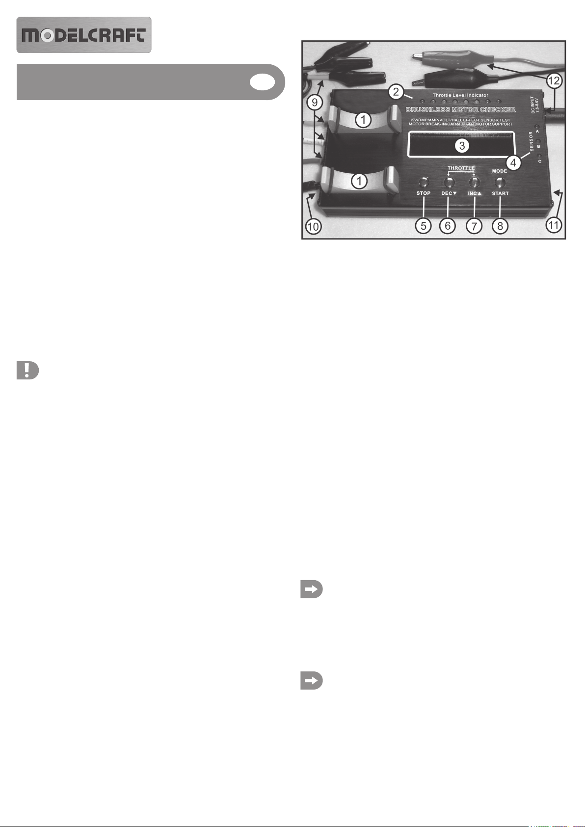
Bild 1
1. Motorauflage
2. LED-Anzeige für die Motordrehzahl
3. Display
4. LED-Anzeige für Hall-Sensoren
5. „Stop“-Taste
6. „Dec“-Taste
7. „Inc“-Taste
8. „Mode/Start“-Taste
9. Buchsen für Motoranschlüsse und Anschlusskabel
10. Buchse für Hall-Sensoren des Motors und Anschlusskabel
11. Umschalter für 2- oder 6-polige Motoren
12. Buchse für Versorgungsspannung mit Anschlusskabel
Informationen zum Betrieb
Funktion 1, Motordaten ermitteln:
Um Motoren optimal für einen angedachten Einsatzzweck anzupassen oder um zu Tuningzwecken mehrere Antriebe zu vergleichen, sind einige technische Daten erforderlich. Der
Voltcraft Brushless-Motor-Tester hilft Ihnen auf einfache Art und Weise bei der Ermittlung
dieser Daten. Zur Messung gehen Sie wie folgt vor:
• Stecken Sie die drei Motoranschlusskabel in die drei Buchsen des Motor-Testers (Bild 1,
Pos. 9). Um immer die gleichen Testbedingungen zu haben, sollten Sie die Kabel immer in
der gleichen Reihenfolge anstecken: A = blau, B = gelb; C = orange. Die genannten Farben
sind bei einer Vielzahl von Motoranschlusskabeln vorhanden.
• Schließen Sie mit den Universal-Klemmen den Test-Motor an diese drei Kabel an. Achten
Sie hierbei auf eventuell vorhandene Farbkodierungen.
Schieben Sie die Isolierhülsen über die Steckkontakte, um Kurzschlüsse zu vermeiden.
Bei Motoren mit Hall-Sensoren verbinden Sie zusätzlich mit dem Sensor-Anschlusskabel für
Hall-Sensoren den Motor mit dem Motor-Tester (Bild 1, Pos. 10). Anschließend legen Sie
den Test-Motor auf die Motorauflage (Bild 1, Pos. 1)
Sollten die am Test-Motor eventuell vorhandenen Farbcodierungen nicht identisch
mit denen des Motor-Testers sein, können Sie die Farbzuordnungen frei wählen.
Für eine Nachvollziehbarkeit bei einem möglichen späteren Test empfehlen wir, die
gewählte Farbcodierung zu notieren.
• Stecken Sie das Universal-Akku-Anschlusskabel an die Buchse am Motor-Tester (Bild 1,
Pos. 12).
• Wählen Sie je nach Art des Test-Motors mit dem Schalter „Car / Flight“ (Bild 1, Pos. 11) eine
Grundkonfiguration des Motor-Testers aus. Für Motoren aus dem Modellflugbereich wählen
Sie „Flight“, für alle anderen Motoren die Stellung „Car“.
Für die Messung und Anzeige der Leerlaufdrehzahl (RPM) sowie den Umdrehungen pro Volt (KV) ist es wichtig, wie viele Pole der Test-Motor hat. BrushlessMotoren für Autos bzw. Schiffe sind meist sehr hochdrehend und mit einem
zweipoligen Anker aufgebaut. Die Schalterstellung „Car“ ist für solche zweipoligen
Motoren vorgesehen.
Die Anzeigewerte im Display zu Leerlaufdrehzahl (RPM) und Umdrehungen pro
Volt (KV) entsprechen bei solchen Motoren den tatsächlichen Werten. In der
Schalterstellung „Flight“ sind die Anzeigewerte nur dann korrekt, wenn Sie einen
Motor mit 6-poligem Anker vermessen.
Hat der zu vermessende Motor mehr als 2 („Car“) oder 6 Pole („Flight“), stimmt die
Displayanzeige zu Drehzahl (RPM) und Umdrehungen pro Volt (KV) nicht mit der tatsächlichen Drehzahl des Motors überein und muss errechnet werden.
Berechnungsbeispiele für einen Motor mit 14-poligem Anker und Schalterstellung „Car“ (2poliger Anker):
Displayanzeige bei V = 8,0 und Displayanzeige bei RPM = 42000
42000 U/min / 8,0 V = 5250 U/min pro Volt = Anzeige im Display bei KV
42000 U/min / 14 (Anzahl der Pole) = 3000 x 2 (Schalterstellung „Car“ für 2-polig)
= 6000 U/min = tatsächliche Drehzahl des Motors
Displayanzeige bei KV = 5250
5250 U/min / 14 (Anzahl der Pole) = 375 x 2 (Schalterstellung „Car“ für 2-polig)
= 750 U/min / Volt = tatsächliche Drehzahl bei KV
Tipp aus der Praxis:
Die maximal mögliche Displayanzeige für Drehzahl (RPM) ist 99999, für Umdrehungen pro Volt (KV) 9999. In wenigen Fällen kann es vorkommen, dass die
maximal mögliche Displayanzeige nicht mehr ausreichend ist. In diesem Fall
vermessen Sie den Motor in der Schalterstellung „Flight“. Bei der Berechnung
müssen Sie dann aber in die Formel statt dem Multiplikator 2 die 6 anwenden.
• Schließen Sie mit den Universalklemmen des Akku-Anschlusskabels (Bild 1, Pos. 12) den
Motor-Tester an einen geeigneten Akku an. Nach dem Anschluss ertönt ein Piepton und das
Display wird beleuchtet. Der Motor-Tester ist nun eingeschaltet. Im Display (Bild 1, Pos. 3)
sehen Sie die aktuelle Betriebsspannung (V).
Beachten Sie beim Anschluss des Motor-Testers an einen Akku unbedingt auf die
richtige Polung. Rot = Plus, schwarz = Minus. Vermeiden Sie Kurzschlüsse! Bei
Nichtbeachtung wird ggf. der Motor-Tester zerstört. Verlust der Gewährleistung/
Garantie!
Tipp aus der Praxis:
Wir empfehlen für die Stromversorgung des Motor-Testers einen hochwertigen 2zelligen Lipo-Akku mit mindestens 3000 mAh und einer Strombelastbarkeit ab
20 C.
In der Praxis haben sich Modellbauer auf ein bestimmtes Steckersystem zum
Anschluss des Akkus an ein Modell bzw. eines Ladegerätes festgelegt. Für einen
komfortablen, verpolungssicheren Anschluss des Motor-Testers empfehlen wir,
das Akku-Anschlusskabel des Motor-Testers mit dem gleichen Steckersystem
auszurüsten.
• Zum Vermessen des Motors drücken Sie kurz auf die „Mode/Start“-Taste (Bild 1, Pos. 8). Der
Motor läuft an. In der LED-Anzeige für die Drehzahl (Bild 1, Pos. 2) leuchten die ersten drei
LEDs. Im Display (Bild 1, Pos. 3) werden die aktuellen Werte für Eingangsspannung (V),
Leerlaufdrehzahl (RPM), Leerlaufstrom (I) und Umdrehungen pro Volt (KV) angezeigt.
• Mit den Tasten „Dec“ (Bild 1, Pos. 6) und „Inc“ (Bild 1, Pos. 7) können Sie nun die Drehzahl
verändern. Drücken Sie „Dec“, wird die Drehzahl niedriger bis zum Stillstand des Motors und
die LEDs erlöschen nacheinander. Drücken Sie „Inc“, wird die Drehzahl erhöht und weitere
LEDs werden leuchten. Die volle Drehzahl ist erreicht, wenn alle LEDs leuchten.
Die Drehzahl sollte grundsätzlich nur langsam erhöht werden. Andernfalls kann es
z.B. bei sehr leistungsstarken Motoren vorkommen, dass bei zu schneller Drehzahlerhöhung der Motortester den Testlauf abbricht (Displayanzeige: „Motor
disconnected“). In diesem Fall trennen Sie den Motor-Tester kurz vom Akku und
beginnen den Test erneut.
• Mit der Taste „Stop“ (Bild 1, Pos. 5) beenden Sie den Testlauf. Im Display werden die letzten
Messwerte eingefroren und können bequem abgelesen werden. Die angezeigten Werte
werden bei einem erneuten Test überschieben bzw. nach dem Trennen vom Akku gelöscht.
Funktion 2, Hall-Sensoren prüfen:
Hall-Sensoren haben bei Brushless-Motoren die Aufgabe, dem Drehzahlsteller eine „Rückmeldung“ zu geben, zu welchem Zeitpunkt sich wo im Motor ein Magnet befindet. Motoren mit
solchen Sensoren wurden zur Anfangszeit der Brushless-Motoren häufig verwendet. Diese
Technik hat den Vorteil, dass ein Drehzahlsteller „zwangsgesteuert“ und somit technisch
einfacher realisiert werden konnte. Durch den technischen Fortschritt werden heutzutage
solche Motoren selten angeboten. Meist sind nur noch Spezial-Motoren mit Hall-Sensoren
ausgestattet. Bei Störungen der Hall-Sensoren hat der Motor zumindest einen Leistungsverlust oder funktioniert gar nicht.
Zur Überprüfung der Hall-Sensoren gehen Sie wie folgt vor:
• Der Anschluss von Motoren mit Hall-Sensoren erfolgt in der gleichen Weise wie unter
„Hinweise zum Betrieb – Motordaten ermitteln“ beschrieben. Zusätzlich müssen Sie das
Sensor-Anschlusskabel in die Buchsen von Motor und Motor-Tester stecken (Bild 1, Pos.
10).
• Der Testmodus für Hall-Sensoren ist automatisch aktiviert, wenn der Motor-Tester an den
Akku angeschlossen wurde bzw. nach dem die Ermittlung von Motordaten mit der Taste
„Stop“ beendet worden ist.
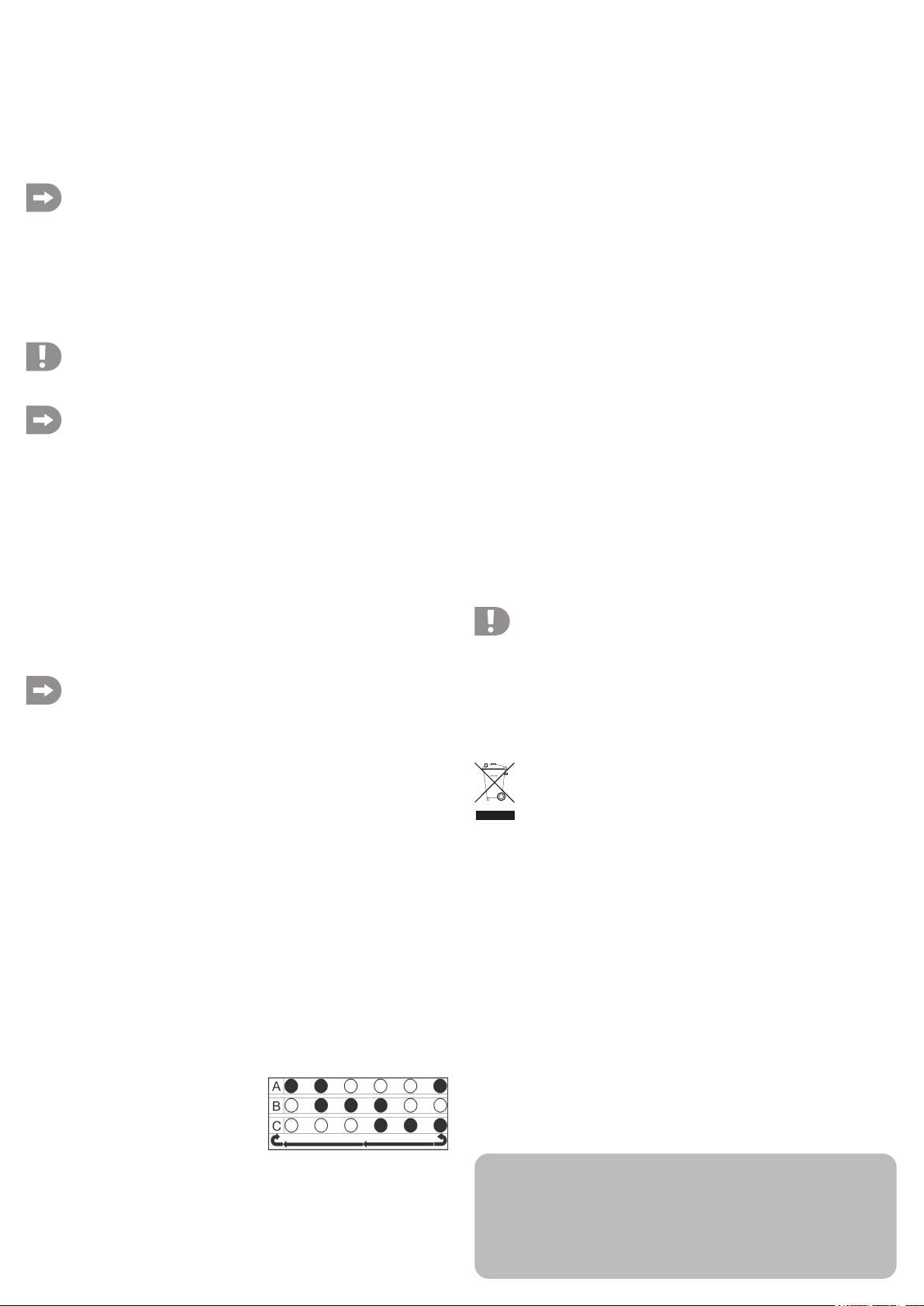
• Die LEDs der Hall-Sensor-Anzeige (Bild 1, Pos. 4)
müssen nun in einer bestimmten Reihenfolge
leuchten. Beachten Sie hierzu Bild 2.
• Drehen Sie den Motor wieder in die gleiche Richtung ein Stück weiter und orientieren Sie
sich an den in Bild 2 gezeigten LED-Anzeigen, bis wieder nur die LED „A“ leuchtet.. Die HallSensoren des Motors sind in Ordnung, wenn die LED-Anzeigen wie in Bild 2 dargestellt zu
sehen sind. Ist diese Reihenfolge anders als aufgezeigt oder leuchten alle LEDs gleichzeitig
bzw. die LEDs leuchten gar nicht, so sind die Hall-Sensoren fehlerhaft.
Funktion 3: „Automatik“
Der Motor-Tester verfügt über eine „Automatik“, die einen angeschlossenen Motor ab einer
Standdrehzahl (ca. 2,5 V) in eine vorher bestimmte Drehzahl (bis ca. 7,2 V) regelt. Die
Intervallgeschwindigkeit kann hierbei variiert werden.
Diese Funktion ist sehr praktisch, wenn z.B. ein Antrieb „einlaufen“ oder eine Funktionskontrolle durchgeführt werden soll. Unter Beachtung der maximal zulässigen Stromstärke von
18A kann dies sogar bei im Modell eingebautem Motor erfolgen. Hierdurch kann ein direkter
Vergleich der Leerlauf-Stromaufnahme des Motors im aus- bzw. eingebauten Zustand und
somit Schlussfolgerungen auf eventuell vorhandene Reibungsverluste des Antriebs ermittelt
werden.
Zur Aktivierung dieser Funktion gehen Sie wie folgt vor:
• Der Anschluss von Motoren erfolgt in der gleichen Weise wie unter „Hinweise zum Betrieb
– Motordaten ermitteln“ beschrieben.
• Zur Aktivierung der Automatik-Funktion drücken Sie für ca. zwei Sekunden die „Mode/Start“Taste. Das Display schaltet jetzt um auf die Anzeige des Automatik-Modus um. Im Display
sehen Sie folgende Werte: „V=7,2V“ (Anzeige blinkt = Voreinstellung des Maximalwertes =
analog zur Spannung steigt oder sinkt die Drehzahl des Motors), „RPM=0, T=5“ und
„I=0,0A“.
• Mit den Tasten „Dec“ und „Inc“ können Sie nun den Maximalwert einstellen. Der geringste
Wert ist 2,5V, der höchste Wert ist 7,2V.
• Drücken Sie die „Stop“-Taste. Nun blinkt „T=5“. Mit den Tasten „Dec“ und „Inc“ können Sie
einen Wert von 1 bis 10 einstellen. Je höher der Wert eingestellt ist, desto länger dauert der
Anstieg von der geringsten Drehzahl (2,5V) bis zu vorher eingestellten Höchstdrehzahl (die
z.B. bei 6,0 V vorherrscht). Wenn Sie die „Dec“-Taste lange genug halten, erscheint im
Display „T=F“. In dieser Stellung ist das Intervall abgeschaltet. Der Motor wird nach
Betätigung der Start-Taste mit der vorher eingestellten Spannung (zwischen 2,5V bis 7,2V)
beginnen, zu laufen.
• Nun kann die Automatik-Funktion mit der „Mode/Start“-Taste gestartet werden. Die Funktion
lässt sich mit der „Stop“-Taste wieder beenden. Wenn Sie in den normalen Test-Modus
zurückwechseln wollen, drücken und halten Sie die „Mode/Start“-Taste für ca. zwei Sekunden.
Achtung!
Wenn Sie die Automatik-Funktion bei einem in ein Modell eingebauten Motor
anwenden, erhöht sich durch die Vielzahl der bewegten bzw. rotierenden Teile
auch die Unfallgefahr. Für solche Testaufbauten empfehlen wir dringend eine
sogfältige Fixierung des Modells auf einem Montageständer. Zudem dürfen die
maximal zulässigen Parameter (siehe technische Daten) nicht überschritten werden.
Entsorgung
Elektrische und elektronische Produkte dürfen nicht in den Hausmüll!
Entsorgen Sie das Produkt am Ende seiner Lebensdauer gemäß den geltenden
gesetzlichen Bestimmungen.
Technische Daten
Betriebsspannung:.............................. 7,4 bis 8,4V
Maximal zulässiger Laststrom: ........... 18A bei 8,4V
Drehzahlanzeige: ................................ max. 99999
Anzeige Umdrehungen/Volt: .............. max. 9999
Anzeigetoleranzen: ............................. +/- 5%
Turns: .................................................. min. 2,5 oder höher
Display:................................................ 2 Zeilen á 16 Zeichen, beleuchtet
Bild 2
• Drehen Sie von Hand die Motorwelle langsam, bis die LED „A“ leuchtet. Danach drehen Sie
den Motor ein Stück weiter (Motor „rastet“ beim nächsten Magneten „ein“). Es müssen nun
die LEDs „A“ und „B“ leuchten.
Diese Bedienungsanleitung ist eine Publikation der Conrad Electronic SE, Klaus-Conrad-Str. 1,
D-92240 Hirschau (www.conrad.com).
Alle Rechte einschließlich Übersetzung vorbehalten. Reproduktionen jeder Art, z. B. Fotokopie,
Mikroverfilmung, oder die Erfassung in elektronischen Datenverarbeitungsanlagen, bedürfen der
schriftlichen Genehmigung des Herausgebers. Nachdruck, auch auszugsweise, verboten.
Diese Bedienungsanleitung entspricht dem technischen Stand bei Drucklegung. Änderung in Technik
und Ausstattung vorbehalten.
© Copyright 2010 by Conrad Electronic SE. V1_0810_01
Connections and function keys
Operating instructions
Version 08/10
Brushless Motor Tester
Item No.: 23 77 43
Intended use
The product consists of a brushless motor tester and different cables to connect the
rechargeable battery and motor.
The motor tester is suitable to measure model-making brushless motors, for example, of size
540 with and without Hall sensors from 2.5 turns and 2 poles (inrunner). It is also possible to
test sensorless motors, from airplane model-making with 6 poles (outrunner). For both
versions the respective presets can be selected. Motors with other pole numbers can also be
measured.
Furthermore, the tester is equipped with an „automatic function“. With this function a brushless
motor can be operated in predetermined function modes.
Any other use than that described above could lead to damage to this product and involves
risks like short circuits, fire, electric shock, etc. Observe all safety instructions in these
operating instructions.
This product complies with all current National and European requirements. All included
corporate names and product descriptions are trade marks of the corresponding owner. All
rights reserved.
Safety Instructions
The warranty will be void in the event of damage caused by failure to observe
these safety instructions! We will not assume any responsibility for any
consequential damage.
We do not accept any liability for personal injury or damage to property
caused by incorrect handling or failure to observe the safety instructions.
The warranty will be null and void in such cases.
• For safety and licensing reasons (CE), unauthorised conversion and/or modification of the
device is not permitted. Do not dismantle the product there are no parts to be adjusted or
maintained. Moreover this causes the warranty to become void!
• The product is not a toy and must be kept out of the reach of children.
• The motor tester must not get damp or wet.
• Always disconnect the rechargeable battery from the motor tester after a test has been
completed.
• The motor tester can be operated with a 6-cell NiMH/NiCd rechargeable battery or a 2-cell
LiPo rechargeable battery (recommended).
• The maximum admissible load current of a motor connected to the motor tester is limited to
18 A at 8.4 V. Not observing the limit values can cause the motor tester and/or the motor to
be damaged. Warranty will become void!
• Only operate the motor tester via an accumulator pack but never via a power supply unit.
• When connecting the motor tester to an accumulator please implicitly observe the correct
polarity: red = plus and black = minus. Non-observance will damage the motor tester.
Warranty will be voided!
• Only connect a single brushless motor to the motor tester.
• The brushless motor tester is not suitable for operation of conventional electric motors with
two connections!
• Avoid blockage of the drive. The resulting currents could damage the motor and/or the motor
tester.
• Before charging the accumulator disconnect the motor tester.
• Observe that there are never any body parts or objects within the moving parts when
operating motors. Risk of injury!
• Handle the product with care. The product can be damaged if crushed, struck or dropped,
even from a low height.
• Do not leave the packaging material lying around carelessly, as such materials can become
dangerous toys in the hands of children.
When in doubt about how to connect or operate the device correctly, or should any questions
arise that are not answered in these operating instructions, contact our Technical Advisory
Service or another expert.
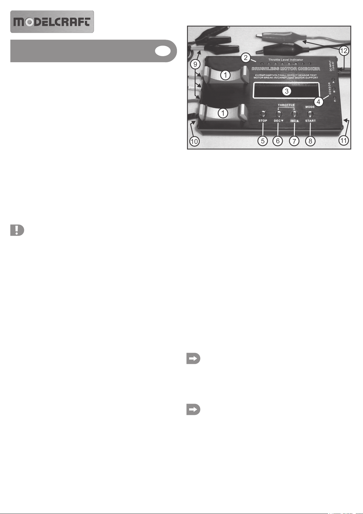
Fig. 1
1. Motor base
2. LED display for the rotation speed of the motor
3. Display
4. LED display for the Hall sensors
5. „Stop“ button
6. „Dec“ button
7. „Inc“ button
8. „Mode/Start“ button
9. Connectors for the motor and connection cables
10. Connector for Hall sensors of the motor and connection cables
11. Switch for 2- or 6-pole motors
12. Connector for power supply with connection cable
Information about operation
Function 1, determine motor data:
In order to optimally adjust motors to their intended use or to compare several motors for tuning
purposes, some technical data are required. The Voltcraft brushless motor tester facilitates
determination of these data. To measure, proceed as follows:
• Plug the three motor connection cables into the three connectors of the motor tester (fig. 1,
pos. 9). In order to always have the same test conditions the cables should always be
connected in the same order: A = blue, B = yellow; C = orange. The mentioned colours can
be found on a multitude of motor connection cables.
• Connect the test motor to these three cables using the universal clamps. When doing so
observe possible colour coding.
Slide the insulation sleeves over the plug contact to avoid short circuits.
Motors with Hall sensors have to be additionally connected to the motor tester via the sensor
connection cable for the Hall sensors (fig. 1, pos. 10). Afterwards put the test motor on the
motor base (fig. 1, pos. 1).
If the colour coding of the test motor is not identical to those of the motor tester you
are free to select the colour assignments. For traceability purposes in a possible
later test, we recommend to write down the decided colour coding.
• Plug the universal accumulator connection cable into the connector at the motor tester (fig.
1, pos. 12).
• Depending on the kind of the test motor select a basic configuration of the motor tester using
the switch „Car / Flight“ (fig 1, pos. 11). For airplane model-making motors select „Flight“, for
all other motors select „Car“.
To measure and display the idle speed (RPM) and the revolutions per Volt (KV) the
number of poles of the test motor is relevant. Brushless motors for cars or ships are
usually high-speed motors constructed with a bipolar anchor. The switch position
„Car“ is intended for such bipolar motors.
The values in the display indicating the idle speed (RPM) and the revolutions per
Volt (KV) correspond to the actual values of such motors. Using the switch position
„Flight“ only results in correct display values with a 6-pole anchor motor.
If the motor to be measured has more than 2 („Car“) or 6 („Flight“) poles the display values
of speed (RPM) and revolutions per Volt (KV) will not match the actual speed of the motor
and will have to be calculated.

Sample calculation for a motor with 14-pole anchor and switch position „Car“ (bipolar
anchor):
Display value at V = 8.0 and display value at RPM = 42000
42000 rpm / 8.0 V = 5250 rpm per Volt = value in the display at KV
42000 rpm / 14 (number of poles) = 3000 x 2 (switch position „Car“ for bipolar)
= 6000 rpm = actual speed of the motor
Display value at KV = 5250
5250 rpm / 14 (number of poles) = 375 x 2 (switch position „Car“ for bipolar)
= 750 rpm / Volt = actual speed at KV
Practical tip:
The maximum possible display value for speed (rpm) is 99999, for revolutions per
Volt (KV) 9999. In a few cases it can occur that the maximum possible display values
are not sufficient. In such case measure the motor in switch position „Flight“.
However, you will then have to use the multiplier 6 instead of 2 in the formula.
• Connect the motor tester to a suitable rechargeable battery using the universal clamps of the
accumulator connection cable (fig. 1, pos. 12). After connecting, a beep is released and the
display is illuminated. Now the motor tester is activated. In the display (fig. 1, pos. 3) you can
see the current operating voltage (V).
When connecting the motor tester to an accumulator please implicitly observe the
correct polarity: red = plus and black = minus. Avoid short circuits! Non-observance
will damage the motor tester. Warranty will become void!
Practical tip:
We recommend to power the motor tester with a high-quality 2-cell accumulator with
at least 3000 mAh and a current load capacity of 20 C and above.
In practice model-makers have committed themselves to a certain plug system to
connect the accumulator to a model or to a charging set. For a comfortable reverse
polarity protected connection of the motor tester, we recommend equipping the
accumulator connection cable of the motor tester with the same plug system.
• To measure the motor briefly press the button „Mode/Start“ (fig. 1, pos. 8). The motor starts.
In the LED display for the speed (fig. 1, pos. 2) the first three LEDs light up. In the display
(fig. 1, pos. 3) the current values of the input voltage (V), idle speed (RPM), idle current (I)
and revolutions per Volt (KV) are displayed.
• You can now change the speed via the buttons „Dec“ (fig. 1, pos. 6) and „Inc“ (fig. 1, pos. 7).
Pressing „Dec“ reduces the speed until standstill of the motor and successively expired
LEDs. Pressing „Inc“ increases the speed and further LEDs will be lit. The full speed is
reached with all LEDs lit.
In principle, the speed should only be increased slowly. Otherwise, for example with
very powerful motors, it can happen that the motor tester terminates the test run if
the speed is increased too fast (display: „Motor disconnected“). In this case
disconnect the motor tester shortly from the accumulator and restart the test.
• The button „Stop“ (fig. 1, pos. 5) ends the test run. In the display the last measurements are
frozen and can be read comfortably. The displayed values will be overwritten by a new test,
and after disconnecting the accumulator, respectively.
Function 2, checking Hall sensors:
Hall sensors in brushless motors have the task of giving „feedback“ to the speed controller,
about where a magnet is positioned in the motor at what point of time. Motors with such
sensors were often used in the early stage brushless motors. This technology has the
advantage that a speed controller could be realised „forcibly controlled“ and thus technically
easier. Such motors are rarely offered today due to the technical progression. Mostly specialpurpose motors are equipped with Hall sensors today. In case of failures of the Hall sensors
the motor has at least a loss of performance or does not function anymore at all.
To review the Hall sensors proceed as follows:
• Connection of motors with Hall sensors is made in the same way as described under
„Information about operation - determine motor data“. Additionally, you have to plug in the
sensor connection cable into the connectors of the motor and the motor tester (fig. 1, pos.
10).
• The test mode for Hall sensor is activated automatically as soon as the motor tester has been
connected to the accumulator, and after the determination of the motor data with the button
„Stop“ has been completed, respectively.
• The LEDs of the Hall sensor display (fig. 1, pos. 4)
now have to be lit in a certain order. For this
observe figure 2.
Function 3: „Automatic“
The motor tester is equipped with an „Automatic“ regulating a connected motor to a
predetermined speed (up to approx. 7.2 V) as of an idle speed (approx. 2.5 V). At this the
interval speeds can be varied.
This function is very practical, for example, if a motor is to be „run in“ or a function check is to
be made. Considering the maximum admissible current of 18A this can even be made for a
motor already built into a model. Thus a direct comparison of the idle current consumption of
the motor dismantled or built-in can be made and thus conclusions can be drawn with regard
to the possible friction losses of the motor.
To activate this function, proceed as follows:
• Connection of motors is made in the same way as described under „Information about
operation - determine motor data“.
• To activate the automatic function keep the button „Mode/Start“ impressed for approx. 2
seconds. The display now switches to the depiction of the automatic mode. In the display the
following values can be seen: „V=7.2V“ (Display flashes = preset of the maximum value =
analogous to the voltage the speed of the motor increases or decreases), „RPM=0, T=5“ and
„I=0.0A“.
• Via the buttons „Dec“ and „Inc“ you can now set the maximum value. The lowest value is
2.5V, the highest value is 7.2V.
• Press „Stop“ button. Now „T=5“ is flashing. Via the buttons „Dec“ and „Inc“ you can now set
a value between 1 to 10. The higher the value is set, the longer the ramp takes from the lowest
speed to the preset maximum speed (e.g., at 6.0V). If the „Dec“ button is impressed long
enough „T=F“ appears in the display. In this position the interval is turned off. After using the
start button the motor will start running with the preset voltage (between 2.5V and 7.2V).
• Now the automatic function can be started using the button „Mode/Start“. The function can
be terminated again with the button „Stop“. If you want to change back to the normal test
mode press and hold the button „Mode/Start“ down for approx. 2 seconds.
Caution!
If you use the automatic function with a motor built-in into a model, the risk of
accidents increases due to the variety of moving or rotating parts. For such a test
setup we highly recommend a thorough fixation of the model on a workstand.
Furthermore the maximum admissible parameters (see technical data) must not be
exceeded.
Disposal
Electrical and electronic products do not belong in the household waste!
Please dispose of the device when it is no longer of use, according to the current
statutory requirements.
Technical Data
Operating voltage: .............................. 7.4 to 8.4 Volt
Maximum admissible load current: .... 18A at 8.4V
Speed display: .................................... max. 99999
Display revolutions/Volt: ..................... max. 9999
Display tolerances: ............................. +/- 5%
Turns: .................................................. at least 2.5 or higher
Display:................................................ 2 lines á 16 characters, illuminated
Fig. 2
• Manually revolve the motor shaft slowly until LED „A“ is lit. Afterwards turn the motor a little
further (motor „locks in place“ at the next magnet). Now both LEDs „A“ and „B“ have to be
lit.
• Turn the motor a little further in the same direction again and follow the LED displays shown
in figure 2 until the LED „A“ is again the only one lit. The Hall sensor of the motor is working,
if the LED displays are shown as depicted in figure 2. If this order is different than depicted
or all LEDs are lit at the same time, and the LEDs are not lit at all, respectively, the Hall
sensors are faulty.
These operating instructions are a publication by Conrad Electronic SE, Klaus-Conrad-Str. 1,
D-92240 Hirschau (www.conrad.com).
All rights including translation reserved. Reproduction by any method, e.g. photocopy, microfilming,
or the capture in electronic data processing systems require the prior written approval by the editor.
Reprinting, also in part, is prohibited.
These operating instructions represent the technical status at the time of printing. Changes in
technology and equipment reserved.
© Copyright 2010 by Conrad Electronic SE.

Accordements et touches de fonction
Notice d’emploi
Version 08/10
Testeur de moteur sans balais
(ou moteur brushless)
N° de commande : 23 77 43
Utilisation conforme
Le produit se compose d’un testeur de moteur sans balais et de différents câbles destinés à
raccorder l’accumulateur au moteur.
Le testeur de moteur est conçu pour mesurer des moteurs sans balais de modèle réduit, de
taille 540 par exemple, avec ou sans capteurs à effet Hall à partir de 2500 tours et de 2 pôles
(moteur « inrunner »). Il est également possible de tester des moteurs sans capteurs avec 6
pôles issus de l’aéromodélisme (moteur « outrunner »). Pour les deux versions, vous pouvez
choisir les préréglages correspondants. Les moteurs avec des nombres de pôles différents
sont également mesurés.
De plus, le testeur dispose d’une « fonction automatique ». Grâce à cette fonction, un moteur
sans balais peut être utilisé en modes de fonctionnement prédéfinis.
Une utilisation autre que celle décrite précédemment peut endommager le produit et entraîner
de ce fait des risques de court-circuit, d’incendie, d’électrocution, etc. Respecter toutes les
consignes de sécurité du manuel d’utilisation.
Ce produit répond aux exigences légales nationales et européennes en vigueur. Tous les
noms d’entreprise et les appellations d’appareil figurant dans ce manuel d’utilisation sont des
marques déposées des propriétaires correspondants. Tous droits réservés.
Consignes de securite
Tout dommage résultant du non-respect de ce manuel d’utilisation entraîne
l’annulation de la garantie ! Nous déclinons toute responsabilité pour les
dommages consécutifs !
De même, nous déclinons toute responsabilité en cas de dommages matériels ou corporels résultant d’une utilisation non conforme aux spécifications ou d’un non-respect des consignes de sécurité ! Dans de tels cas la
garantie est annulée.
• Pour des raisons de sécurité et d’homologation (CE), il est interdit de modifier la construction
et/ou de transformer l’appareil de son propre gré. Ne pas démonter le produit, aucun élément
ne nécessite de réglage ou de maintenance de votre part. De plus, cela entraînerait
l’annulation de la garantie.
• Ce produit n’est pas un jouet, le tenir hors de portée des enfants.
• Le testeur de moteur ne peut être ni mouillé ni humide.
• Toujours débrancher l’accumulateur du testeur de moteur quand le test est terminé.
• Le testeur de moteur peut être utilisé avec des accumulateurs à 6 rangées NiMH/NiCd ou
à 2 rangées LiPo (recommandé).
• Le courant de charge autorisé maximal d’un testeur de moteur branché à un moteur est de
8,4 V sur 18 A. En cas de non-respect des valeurs limites, le moteur et/ou le testeur de moteur
le cas échéant sont détruits. Cela entraîne l’annulation de la garantie !
• N’utiliser le testeur de moteur que via une batterie d’accumulateur, jamais via un bloc
d’alimentation.
• Respecter impérativement la polarité exacte lorsque vous branchez le testeur de moteur à
un accumulateur. Rouge = plus, noir = moins. En cas de non-respect, le testeur de moteur
est détruit. Cela entraîne l’annulation de la garantie !
• Ne brancher qu’un seul moteur sans balais au testeur de moteur.
• Le testeur de moteur sans balais n’est pas conçu pour le fonctionnement de moteurs
electriques traditionnels à deux branchements !
• Éviter de caler la propulsion. Les courants en découlant pourraient détruire le moteur et/ou
le testeur de moteur.
• Avant de recharger l’accumulateur le débrancher du testeur de moteur.
• S’assurer, lors de la manipulation des moteurs, que des parties du corps ou des objets ne
se trouvent jamais dans les parties tournantes. Risque de blessure !
• Manipuler le produit avec soin. Des chocs, des coups ou des chutes, même de faible
hauteur, l’endommageraient.
• Ne pas laisser le matériel d’emballage sans surveillance, il pourrait constituer un jouet
dangereux pour les enfants.
En cas de doute quant au raccordement ou au fonctionnement correct ou si vous avez des
questions pour lesquelles vous ne trouvez aucune réponse dans ce manuel d’utilisation,
contactez notre service technique ou un spécialiste.
Illustration 1
1. Support du moteur
2. Voyants LED pour la vitesse de rotation du moteur
3. Écran
4. Voyants LED pour les capteurs à effet Hall
5. Touche « Stop »
6. Touche « Dec »
7. Touche « Inc »
8. Touche « Mode/Start »
9. Prises pour raccordements du moteur et câbles de raccordement
10. Prises pour capteurs à effet Hall du moteur et câble de raccordement
11. Interrupteur pour les moteurs à 2 ou 6 pôles
12. Prise pour tension d’alimentation avec câble de raccordement
Informations sur le fonctionnement
Fonction 1, identifier les données du moteur :
Pour adapter des moteurs de façon optimale afin de les utiliser comme vous l’avez prévu ou
pour comparer plusieurs commandes afin d’optimiser les performances, quelques données
techniques sont nécessaires. Le testeur de moteur sans balais Voltcraft vous aide à identifier
ces données très simplement. Pour mesurer, procéder comme suit :
• Brancher les trois câbles de raccordement du moteur dans les trois prises du testeur de
moteur (Illustration 1, Pos. 9). Pour toujours avoir les mêmes conditions de test, mettre les
câbles toujours dans le même ordre : A = bleu, B = jaune, C = orange. Les couleurs citées
sont disponibles sous une multitude de câbles de raccordement du moteur.
• Raccorder le moteur test à ces trois câbles à l’aide d’une pince universelle. Observer les
codes couleurs disponibles éventuels.
Pousser les tubes isolants sur les contacts à fiche pour éviter des court-circuits.
Pour des moteurs avec capteurs à effet Hall, raccorder ensuite le moteur au testeur de
moteur (illustration 1, pos. 10) à l’aide du câble de raccordement du capteur pour des
capteurs à effet Hall. Poser ensuite le moteur test sur le support du moteur (illustration 1,
pos. 1).
Si les codes couleurs éventuellement disponibles sur le moteur-test ne sont pas
identiques à ceux du testeur de moteur, choisir n’importe quel ordre de couleur.
Nous vous recommandons de noter les codes couleurs choisis pour faciliter un
nouveau test éventuel.
• Brancher le câble de raccordement de l’accumulateur universel sur la prise du testeur de
moteur (illustration 1, pos.12).
• Choisir une configuration de base du testeur de moteur à l’aide de l’interrupteur « Car/
Flight » (Illustration 1, pos. 11) selon le type du moteur de test. Pour des moteurs de
l’aéromodélisme, choisir « Flight », pour tous les autres moteurs la position « Car ».
Pour la mesure et l’indication de la vitesse de rotation au point mort (RPM) ainsi que
pour les tours par volt (KV), il es important de savoir combien de pôles a le moteur.
Les moteurs sans balais pour voitures ou pour bateaux ont pour la plupart une
vitesse de rotation élevée et sont construit avec un induit bipolaire La position
« Car » est prévue pour de tels moteurs bipolaires.
La valeur indiquée sur l’écran de visualisation pour la vitesse de rotation au point
mort (RPM) et les tours par volt (KV) correspondent aux valeurs réelles pour de tels
moteurs. En position « Flight », les valeurs indiquées sur l’écran de visualisation ne
sont exactes que si vous mesurez un moteur avec 6 pôles.
Si le moteur à mesurer a plus 2 pôles (« Car ») ou plus de 6 pôles (« Flight »), les indications sur
l’écran de visualisation concernant la vitesse de rotation (RPM) et les tours par Volt (KV) ne
correspondent pas à la vitesse de rotation réelle du moteur et doivent être calculées.

Ex. de calcul pour un moteur avec un induit à 14 pôles et la position « Car » (induit bipolaire) :
Indication sur l’écran de visualisation V = 8,0 et RPM = 42000
42000 U/min / 8,0 V = 5250 U/min par Volt = indications sur l’écran de visualisation en KV
42000 U/min / 14 (nombre de pôles) = 3000 x 2 (Position « Car » pour bipolaire)
= 6000 U/min = vitesse de rotation réelle du moteur
Indication sur l’écran de visualisation si KV = 5250
5250 U/min / 14 (nombre de pôles) = 375 x 2 (Position « Car » pour bipolaire)
= 750 U/min = vitesse de rotation réelle du moteur
Renseignement concernant la pratique :
L’indication possible maximale sur l’écran de visualisation de la vitesse de rotation
(RPM) est de 99999, pour les tours par Volt (KV) de 9999. Dans certains cas il se
peut que l’indication possible maximale ne soit plus suffisante. Dans ce cas,
mesurer le moteur en position « Flight ». Pour calculer, il faut appliquer ensuite le
multiplicateur 6 à la place du 2 dans la formule.
• Raccorder le moteur de test à l’accumulateur approprié à l’aide des pinces universelles du
câble de raccordement de l’accumulateur (illustration 1, pos. 12). Après le raccordement on
entend un bip et l’écran de visualisation s’allume. Le testeur de moteur est à présent en
service. On peut voir sur l’écran de visualisation (illustration 1, pos. 3) la tension de service
(V) actuelle.
Respecter impérativement la polarité exacte lorsque vous branchez le testeur de
moteur à un accumulateur. Rouge = plus, noir = moins. Éviter les courts-circuits !
En cas de non-respect, le testeur de moteur est détruit. Cela entraîne l’annulation
de la garantie !
Renseignement concernant la pratique :
Nous recommandons pour l’alimentation électrique du testeur de moteur un
accumulateur Lipo à deux rangées de haute valeur avec minimum 3000 mAh et une
charge électrique admissible à partir de 20 C.
Dans la pratique, des modélistes se sont engagés sur un système de prise
déterminé pour raccorder l’accumulateur au modèle ou au chargeur. Pour un
raccordement du testeur de moteur confortable en protégeant la polarité, nous vous
recommandons d’équiper le câble de raccordement de l’accumulateur du testeur
de moteur avec même système de prise.
• Pour mesurer le moteur pousser brièvement sur la touche « Mode/Start » (illustration 1, pos.
8). Le moteur démarre. Les trois premières LED s’allument dans le voyant LED pour le
nombre de tour (illustration 1, pos 2). Sont visibles sur l’écran de visualisation (illustration 1,
pos. 3) les valeurs actuelles pour la tension d’entrée (V), la vitesse de rotation au point mort
(RPM), le courant au point mort (l) et les tours par volt (KV).
• À l’aide de la touche « Dec » (illustration 1, pos. 6) et « Inc » (illustration 1, pos 7) vous
pouvez maintenant modifier le nombre de tours. Appuyer sur « Dec », le nombre de tours
diminue jusqu’à l’arrêt du moteur et les LED s’éteignent une après l’autre. Appuyer « Inc »,
le nombre de tours augmente et les autres LED s’allument. Le nombre de tours plein est
atteint quand toutes les LED sont allumées.
Le nombre de tours devrait être augmenté fondamentalement doucement. Dans le
cas contraire, il se peut, par exemple dans le cas de moteurs très performants, que
le test s’interrompe par une augmentation trop rapide du nombre de tours du testeur
de moteur (indication sur l’écran de visualisation : « Motor disconnected »). Dans
ce cas, couper le testeur de moteur brièvement de l’accumulateur et recommencer
le test.
• À l’aide de la touche « Stop » (illustration 1, pos. 5), vous pouvez interrompre le déroulement
du test. Les dernières valeurs de mesures sont bloquées sur l’écran de visualisation et
peuvent être aisément lues. Les valeurs indiquées seront écrasées lors du prochain test ou
effacées après avoir débranché l’accumulateur.
Fonction 2, vérifier les capteurs à effet Hall :
Les capteurs à effet Hall ont, pour les moteurs sans balais, la tâche de donner « une réaction » au
compte-tours et d’indiquer à quel moment et où se trouve l’aimant dans le moteur. Des moteurs
munis de tels capteurs ont été utilisés très souvent au début des moteurs sans balais. Cette
technique avait un avantage : un compte-tours pouvait être réalisé « par la contrainte » et donc
facilement techniquement. Grâce aux progrès techniques de tels moteurs sont rarement proposés
de nos jours. La plupart du temps seuls les moteurs spéciaux avec capteurs à effet Hall sont encore
autorisés. En cas d’anomalie des capteurs à effet Hall le moteur a au moins une perte de rendement
ou ne fonctionne plus du tout.
Pour contrôler les capteurs à effet Hall, procéder comme suit :
• Le raccordement des moteurs à capteurs à effet Hall se fait comme décrit sous « Consignes
pour le fonctionnement - identifier les données du moteur ». En plus, vous devez insérer le
câble de raccordement du capteur dans les prises du moteur et du testeur de moteur
(illustration 1, pos. 10).
• Le mode test pour les capteurs à effet Hall est automatiquement activé dès que le testeur
de moteur est raccordé à l’accumulateur ou après que l’identification des données du moteur
a été terminée à l’aide de la touche « Stop ».
• Les LED du voyant du capteur à effet Hall (illustration 1, pos. 4) doivent s’allumer maintenant dans
un ordre défini. Tenir compte ici de l’illustration 2.
Illustration 2
• Tourner l’arbre du moteur lentement à la main jusqu’à ce que la LED « A » s’allume. Tourner
ensuite le moteur un peu plus loin (le moteur s’« enclenche » au prochain aimant). Les LED
« A » et « B » s’allument maintenant.
• Tourner à nouveau le moteur dans la même direction un peu plus loin et orienter vers les
voyants LED comme montré sur l’illustration 2 jusqu’à ce que la LED « A » soit à nouveau
la seule allumée. Les capteurs à effet Hall du moteur sont en ordre quand les voyants LED
sont comme sur l’illustration 2. Si cette ordre est différent de celui indiqué ou que toutes les
LED sont allumées en même temps ou qu’elles ne sont pas du tout allumées, les capteurs
à effet Hall sont défectueux.
Fonction 3 : « Automatique »
Le testeur de moteur dispose d’un mode « automatique », qui régule un moteur raccordé à
partir du RPM statique (env. 2,5 V) en une vitesse de rotation définie (env. 7,2 V). La vitesse
d’intervalle peut être variée.
Cette fonction est très pratique quand par exemple une commande de « rodage » ou un
contrôle de fonction doit être réalisé. En observant l’intensité de courant électrique maximal
autorisé de 18A, ceci peut se faire sur un moteur encastré dans le modèle. De cette façon, on
peut établir une comparaison directe de la prise de courant au point mort du moteur dans un
état encastré ou aménagé et en déduire d’éventuelles déperditions d’énergie disponible de
la commande.
Pour mesurer, procéder comme suit :
• Le raccordement des moteurs se fait comme décrit sous « Consignes pour le fonctionnement - identifier les données du moteur ».
• Pour activer la fonction automatique appuyer sur la touche « Mode/Start » environ deux
secondes. L’écran de visualisation indique maintenant le mode automatique. Voici les
valeurs affichées sur l’écran de visualisation : « V=7,2 » (L’indication clignote = préréglage
de la valeur maximale = selon la tension, la vitesse de rotation du moteur augmente ou
diminue, « RPM=0, T=5 » et « I=0,0A ».
• Vous pouvez maintenant installer la valeur maximale à l’aide des touches « Dec » et « Inc ».
La valeur la plus basse est 2,5V, la plus haute 7,2V.
• Appuyer sur la touche « Stop ». Maintenant « T=5 » clignote. Vous pouvez maintenant
entrer une valeur entre 1 et 10 à l’aide des touches « Dec » et « Inc ». Plus la valeur est haute
plus longtemps durera la montée de la vitesse de rotation la plus faible (2,5V) jusqu’à la
vitesse de rotation maximale établie (qui prédomine par exemple par 6,0 V). Si vous laissez
la toucher « Dec » maintenue assez longtemps, « T=F » apparaît sur l’écran de visualisation. Dans cette position, l’intervalle est mis en marche. Le moteur commencera à tourner
après l’activation de la touche Start avec la tension préalablement établie (entre 2,5V et
7,2V).
• Maintenant la fonction automatique peut être démarrée à l’aide de la touche « Mode/Start ».
Pour arrêter la fonction, appuyer sur la touche « Stop ». Si vous voulez revenir au mode de
test normal, appuyer et maintenir la touche « Mode/Start » environ deux secondes.
Attention !
Si vous appliquez la fonction automatique sur un moteur encastré au modèle, le
risque d’accident augmente à cause de la multitude de parties en mouvement et en
rotation. Pour de tels tests, nous recommandons expressément une fixation
soigneuse du modèle sur un support de montage. De plus, les paramètres
maximaux autorisés (voir les données techniques) ne peuvent pas être dépassés.
Élimination
Les produits électriques et électroniques ne peuvent pas être jetés aux ordures
ménagères !
Éliminer le produit à la fin de sa durée de vie conformément aux dispositions légales
en vigueur.
Donnéés techniques
Tension de service : ........................... 7,4 jusque 8,4V
Courant de charge maximal autorisé :18A sous 8,4V
Indication de nombre de tour : ........... max. 99999
Indication tours/volt : .......................... max. 9999
Tolérances d’indication : .................... +/- 5%
Tours : ................................................. min. 2,5 ou plus
Écran de visualisation : ...................... 2 lignes à 16 caractères s’allument
Ce mode d'emploi est une publication de la société Conrad Electronic SE, Klaus-Conrad-Str. 1,
D-92240 Hirschau (www.conrad.com).
Tous droits réservés, y compris de traduction. Toute reproduction, quelle qu'elle soit (p. ex.
photocopie, microfilm, saisie dans des installations de traitement de données) nécessite une
autorisation écrite de l'éditeur. Il est interdit de le réimprimer, même par extraits.
Ce mode d'emploi correspond au niveau technique du moment de la mise sous presse. Sous réserve
de modifications techniques et de l'équipement.
© Copyright 2010 by Conrad Electronic SE.

Aaansluitingen en Functietoetsen
Gebruiksaanwijzing
Versie 08/10
Brushless-Motortester
Bestelnr.: 23 77 43
Voorgeschreven gebruik
Het product bestaat uit een Brushless-motortester en verschillende kabels voor de aansluiting
van accu en motor.
De motortester is geschikt voor het meten van Brushless-motoren in de modelbouw, zoals het
formaat 540 met en zonder Hall-sensoren vanaf 2,5 turns en 2 polen (in-runner-motor). Het
is ook mogelijk, sensorloze motoren uit de vliegtuigmodelbouw met 6 polen (out-runner-motor)
te testen. Voor beide versies kunnen dienovereenkomstig voorinstellingen worden gekozen.
Motoren met afwijkende poolaantallen kunnen eveneens worden gemeten.
Bovendien beschikt de tester over een “automaat”-functie’’. In deze functie kan een Brushlessmotor in vooraf bepaalde functiemodi worden gebruikt.
Een ander gebruik dan hiervoor beschreven kan leiden tot beschadiging van het product met
daarmee verbonden risico’s zoals kortsluiting, brand en elektrische schok. Neem alle veiligheidsaanwijzingen in deze gebruiksaanwijzing in acht.
Dit product voldoet aan de wettelijke, nationale en Europese eisen. Alle vermelde
firmanamen en productaanduidingen zijn handelsmerken van de betreffende eigenaar.
Alle rechten voorbehouden.
Veiligheidsaanwijzingen
Bij schade, veroorzaakt door niet-naleving van deze gebruiksaanwijzing,
vervalt de garantie! Wij aanvaarden geen aansprakelijkheid voor gevolgschade!
Wij aanvaarden geen aansprakelijkheid voor materiële schade of persoonlijk
letsel, veroorzaakt door onvakkundig gebruik of het niet in acht nemen van
de veiligheidsaanwijzingen! In dergelijke gevallen komt het recht op vrijwaring/garantie te vervallen.
• Uit veiligheid- en toelatingsoverwegingen (CE) is het eigenmachtig ombouwen en/of
wijzigen van het apparaat niet toegestaan. Demonteer het product niet, het bevat geen
onderdelen die door u ingesteld of onderhouden moeten worden. Bovendien komt daardoor
de vrijwaring/garantie te vervallen!
• Het product is geen speelgoed, het hoort niet thuis in kinderhanden.
• De motortester mag niet vochtig of nat worden.
• Na het beëindigen van de test de accu altijd van de motortester loskoppelen.
• De motortester kan met NiMH/NiCd-accu’s met 6 cellen of LiPo-accu’s met 2 cellen
(aanbevolen) worden gebruikt.
• De maximaal toegestane laststroom van een op een motortester aangesloten motor is bij 8,4
V beperkt tot 18 A. Als de grenswaarden niet in acht worden genomen kan de motortester
en/of de motor onherstelbaar worden beschadigd. Verlies van de vrijwaring/garantie!
• Gebruik de motortester uitsluitend via een accupack, nooit via een netvoedingadapter.
• Let bij de aansluiting van de motortester op een accu in ieder geval op de juiste poling: Rood
= plus, zwart = min. Wordt dit niet nageleefd, dan wordt de motortester onherstelbaar
beschadigd. Verlies van de vrijwaring/garantie!
• Sluit slechts een enkele Brushless-motor op de motortester aan.
• De Brushless-motortester is niet geschikt voor de werking van conventionele elektromotoren
met twee aansluitingen!
• Vermijd het blokkeren van de aandrijving. De hieruit ontstane stromen kunnen de motor en/
of de motortester onherstelbaar beschadigen.
• Koppel de accu vóór het laden van de accu los van de motortester.
• Let erop, dat zich tijdens het gebruik van motoren nooit lichaamsdelen of voorwerpen in
draaiende onderdelen bevinden. Kans op verwondingen!
• Ga voorzichtig met het product om. Door stoten, slagen of een val, zelfs van geringe hoogte,
raakt het beschadigd.
• Laat het verpakkingsmateriaal niet achteloos liggen, dit kan voor kinderen gevaarlijk
speelgoed betekenen.
Mochten er onduidelijkheden bestaan over de juiste aansluiting resp. werking of vragen zijn,
die niet in de gebruiksaanwijzing worden beantwoord, neem dan contact op met onze
technische helpdesk of een andere vakman.
Afb. 1
1. Motorsteun
2. LED-indicator voor het motortoerental
3. Display
4. LED-indicator voor Hall-sensoren
5. “Stop”-toets
6. “Dec”-toets
7. “Inc”-toets
8. “Mode/Start”-toets
9. Bussen voor motoraansluitingen en aansluitkabel
10. Bus voor Hall-sensoren van de motor en aansluitkabel
11. Omschakelaar voor motoren met 2 of 6 polen
12. Bus voor voeding met aansluitkabel
Informatie omtrent de werking
Functie 1, motorgegevens vaststellen:
Om motoren optimaal aan te passen op een bepaalde toepassing of om meerdere aandrijvingen uit tuningoverwegingen te vergelijken zijn enige technische gegevens noodzakelijk. De
Voltcraft Brushless-motortester helpt u deze gegevens op eenvoudige wijze vast te stellen.
Voor het meten gaat u als volgt te werk:
• Steek de drie motoraansluitkabels in de drie bussen van de motortester (afb. 1, pos. 9). Om
steeds over dezelfde testcondities te beschikken, moet u de kabels er altijd in dezelfde
volgorde opsteken: A = blauw, B = geel; C = oranje. De genoemde kleuren zijn bij talrijke
motoraansluitkabels aanwezig.
• Sluit met de universele klemmen de testmotor op deze drie kabels aan. Let hierbij op
eventueel aanwezige kleurcoderingen.
Schuif de isoleerhulzen over de steekcontacten, om kortsluitingen te vermijden.
Bij motoren met Hall-sensoren verbindt u buiten de sensoraansluitkabels voor Hall-sens-
oren de motor met de motortester (afb. 1, pos. 10). Vervolgens plaatst u de testmotor op de
motorsteun (afb. 1, pos. 1).
Mochten de op de testmotor eventueel aanwezige kleurcoderingen niet identiek
zijn aan die van de motortester, dan kunt u de kleurtoekenningen zelf kiezen. Wij
adviseren u de gekozen kleurcodering te noteren, zodat u deze er bij een eventuele
latere test op na kunt slaan.
• Steek de universele accu-aansluitkabel op de bus op de motortester (afb. 1, pos. 12).
• Kies afhankelijk van het soort testmotor met de schakelaar “Car / Flight” (afb. 1, pos. 11) een
basisconfiguratie van de motortester. Voor motoren uit de modelvliegtuigbouw kiest u
“Flight”, voor alle andere motoren de stand “Car”.
Ú Voor het meten en weergeven van het nullasttoerental (RPM) alsook de
omdraaiingen per Volt (KV) is het belangrijk, hoe veel polen de testmotor heeft.
Brushless-motoren voor auto’s resp. schepen hebben meestal een zeer hoog
toerental en beschikken over een tweepolig anker. De schakelstand “Car” is
bestemd voor dergelijke tweepolige motoren.
De weergavewaarde in de display m.b.t. tot nullasttoerental (RPM) en omdraaiingen
per Volt (KV) komen bij dergelijke motoren overeen met de daadwerkelijke waarden.
In de schakelstand “Flight” zijn de weergavewaarden alleen dan juist, als u een
motor met 6-polig anker meet.
Als de te meten motor meer dan 2 (“Car”) of 6 polen (“Flight”) heeft, klopt de displayweergave
m.b.t. toerental (RPM) en omdraaiingen per Volt (KV) niet meer met het daadwerkelijke
toerental van de motor en moet worden berekend.

Berekeningsvoorbeelden een motor met 14-polig anker en schakelstand “Car” (2-polig
anker):
Displayweergave bij V = 8,0 en displayweergave bij RPM = 42000
42000 rpm / 8,0 V = 5250 rpm per Volt = weergave in de display bij KV
42000 rpm / 14 (aantal polen) = 3000 x 2 (schakelstand “Car” voor 2-polig)
= 6000 rpm = daadwerkelijke toerental van de motor
Displayweergave bij KV = 5250
5250 rpm / 14 (aantal polen) = 375 x 2 (schakelstand “Car” voor 2-polig)
= 750 rpm = daadwerkelijke toerental bij KV
Tip uit de praktijk:
De maximaal mogelijke displayweergave voor toerental (RPM) is 99999, voor
omdraaiingen per Volt (KV) 9999. In uitzonderingsgevallen kan het voorkomen, dat
de maximaal mogelijke displayweergave niet meer voldoende is. In dit geval meet
u de motor in de schakelstand “Flight”. Bij de berekening moet u dan echter in de
formule met 6 vermenigvuldigen in plaats van met 2.
• Sluit met de universele klemmen van de accu-aansluitkabel (afb. 1, pos. 12) de motortester
aan op een geschikte accu. Na het aansluiten klinkt een pieptoon en gaat de display
branden. De motortester is nu ingeschakeld. In de display (afb. 1, pos. 3) ziet u de actuele
bedrijfsspanning (V).
Let bij de aansluiting van de motortester op een accu in ieder geval op de juiste
poling. Rood = plus, zwart = min. Vermijd kortsluitingen! Wordt dit niet nageleefd,
dan wordt de motortester eventueel onherstelbaar beschadigd. Verlies van de
vrijwaring/garantie!
Tip uit de praktijk:
Wij adviseren voor de voeding van de motortester een hoogwaardige Lipo-accu
met 2 cellen met ten minste 3000 mAh en een stroombelastbaarheid vanaf 20°C.
In de praktijk zitten modelbouwers voor de aansluiting van de accu op een model
resp. een lader aan een bepaald stekkersysteem vast. Voor een comfortabel, tegen
poolverwisseling beveiligde aansluiting van de motortester adviseren wij de accuaansluitkabel van de motortester uit te rusten met hetzelfde stekkersysteem.
• Druk voor het meten van de motor kort op de “Mode/Start”-toets (afb. 1, pos. 8). De motor
start. In de LED-indicator voor het toerental (afb. 1, pos. 2) gaan de eerste drie LED’s
branden. In de display (afb. 1, pos. 3) worden de actuele waarden voor ingangsspanning (V),
nullasttoerental (RPM), nullaststroom (I) en omdraaiingen per Volt (KV) weergegeven.
• Met de toetsen “Dec” (afb. 1, pos. 6) en “Inc” (afb. 1, pos. 7) kunt u nu het toerental wijzigen.
Drukt u op “Dec”, dan gaat het toerental omlaag tot de motor stilstaat en gaan de LED’s één
voor één uit. Drukt u op “Inc”, dan gaat het toerental omhoog en gaan meer LED’s branden.
Het volledige toerental is bereikt als alle LED’s branden.
Het toerental moet in principe slechts langzaam worden verhoogd. Anders kan het
bij zeer krachtige motoren bijv. gebeuren, dat bij te snelle toerentalverhoging de
motortester de testrun afbreekt (displayweergave: “Motor disconnected”). In dit
geval koppelt u de motortester kort van de accu en begint u de test opnieuw.
• Met de toets “Stop” (afb. 1, pos. 5) beëindigt u de testrun. In de display worden de laatste
meetwaarden bevroren en kunnen gemakkelijk worden afgelezen. De weergegeven waarden worden bij een nieuwe test overschreven resp. na het loskoppelen van de accu gewist.
Functie 2, Hall-sensoren controleren:
Hall-sensoren hebben bij Brushless-motoren de opgave, de toerental-insteller een “terugkoppeling” te geven, op welk tijdstip zich waar in de motor een magneet bevindt. Motoren met
dergelijke sensoren werden aan het begin van de Brushless-motoren vaak gebruikt. Deze
techniek heeft het voordeel, dat een toerental-insteller “desmodromisch” en dus technisch
eenvoudiger kan worden gerealiseerd. Door de technische vooruitgang worden vandaag de
dag dergelijke motoren zelden aangeboden. Meestal zijn uitsluitend nog speciale motoren
met Hall-sensoren uitgerust. Bij storingen van de Hall-sensoren lijdt de motor ten minste
prestatieverlies of functioneert helemaal niet meer.
Om de Hall-sensoren te controleren gaat u als volgt te werk:
• De aansluiting van motoren met Hall-sensoren geschiedt op dezelfde wijze als onder
“Gebruiksaanwijzingen – Motorgegevens vaststellen” beschreven. Teven moet u de
sensoraansluitkabel in de bussen van motor en motortester steken (afb. 1, pos. 10).
• De testmodus voor Hall-sensoren is automatisch geactiveerd, als de motortester op de accu
werd aangesloten resp. nadat de vaststelling van motorgegevens met de toets “Stop” is
beëindigd.
• De LED’s van de Hall-sensorindicator (afb. 1, pos.
4) moeten nu in een bepaalde volgorde gaan
branden. Neem hiervoor afb. 2 in acht.
Functie 3: “automaat”
De motortester beschikt over een “automaat”, die een aangesloten motor vanaf een nullasttoerental (ca. 2,5 V) in een vooraf bepaald toerental (tot ca. 7,2 V) regelt. De intervalsnelheid
kan hierbij gevarieerd worden.
Deze functie is zeer praktisch, als bijv. een aandrijving moet “inlopen” of een werkingscontrole
moet worden doorgevoerd. Met inachtname van de maximaal toegestane stroomsterkte van
18 A kan dit zelfs bij een in een model ingebouwde motor plaatsvinden. Hierdoor kan een
directe vergelijking worden gemaakt van het nullastverbruik van de motor in de uit- resp.
ingebouwde toestand en dus slotconclusies worden getrokken betreft eventueel aanwezige
wrijvingsverliezen van de aandrijving.
Voor de activering van deze functie gaat u als volgt te werk:
• De aansluiting van motoren geschiedt op dezelfde wijze als onder “Gebruiksaanwijzingen
– Motorgegevens vaststellen” beschreven.
• Om de automaatfunctie te activeren drukt u ca. twee seconden op de “Mode/Start”-toets. De
display schakelt nu over naar de weergave van de automaat-modus. In de display ziet u de
volgende waarden: “V=7,2V” (indicator knippert = voorinstelling van de maximale waarde =
analoog met de spanning stijgt of daalt het toerental van de motor), “RPM=0, T=5” en
“I=0,0A”.
• Met de toetsen “Dec” en “Inc” kunt u nu de maximale waarde instellen. De laagste waarde
is 2,5V, de hoogste waarde is 7,2V.
• Druk op de “Stop”-toets. Nu knippert “T=5”. Met de toetsen “Dec” en “Inc” kunt u nu een
waarde van 1 t/m 10 instellen. Hoe hoger de waarde is ingesteld, des te langer duurt het
oplopen van het laagste toerental (2,5V) naar het eerder ingestelde hoogste toerental (die
bijv. bij 6,0 V overheerst). Als u de “Dec”-toets lang genoeg vasthoudt, verschijnt in de
display “T=F”. In deze stand is de interval uitgeschakeld. De motor zal na bediening van de
Start-toets met de eerder ingestelde spanning (tussen 2,5V - 7,2V) beginnen te lopen.
• Nu kan de automaatfunctie met de “Mode/Start”-toets worden gestart. De functie kan met
de “Stop”-toets weer worden beëindigd. Als u terug wilt naar de normale Test-modus, drukt
u op de “Mode/Start”-toets en houdt deze ca. twee seconden ingedrukt.
Let op!
Als u de automaatfunctie gebruikt bij een in een model ingebouwde motor, wordt
door de talrijke bewegende resp. roterende delen ook het risico op ongelukken
groter. Voor dergelijke testoprichtingen adviseren wij dringen een zorgvuldige
fixatie van het model op een montagestandaard. Bovendien mogen de maximaal
toegestane parameters (zie technische gegevens) niet worden overschreden.
Afvoer
Elektrische en elektronische producten mogen niet in het huishoudelijk afval!
Voer het product aan het einde van zijn levensduur af volgens de geldende
wettelijke bepalingen.
Technische gegevens
Bedrijfsspanning: ................................ 7,4 - 8,4V
Maximaal toegestane laststroom: ...... 18A bij 8,4V
Toerentalweergave: ............................ max. 99999
Weergave omdraaiingen/Volt: ........... max. 9999
Weergavetoleranties: ......................... +/- 5%
Turns: .................................................. min. 2,5 of hoger
Display:................................................ 2 regels á 16 tekens, verlicht
Afb. 2
• Draai de motoras langzaam met de hand, tot LED “A” brandt. Vervolgens draait u de motor
een stuk verder (motor “klikt” bij de volgende magneet “vast”). Nu moeten de LED’s “A” en
“B” branden.
• Draai de motor weer in dezelfde richting een stuk verder en oriënteert u zich op de in afb.
2 getoonde LED-indicatoren, tot weer alleen LED “A” brandt.. De Hall-sensoren van de
motor zijn in orde, als de LED-indicatoren zoals in afb. 2 weergegeven te zien zijn. Is de
volgorde anders dan weergegeven of branden alle LED’s gelijktijdig resp. helemaal niet, dan
zijn de Hall-sensoren defect.
Deze gebruiksaanwijzing is een publicatie van de firma Conrad Electronic SE, Klaus-Conrad-Str. 1,
D-92240 Hirschau (www.conrad.com).
Alle rechten, vertaling inbegrepen, voorbehouden. Reproducties van welke aard dan ook, bijvoorbeeld
fotokopie, microverfilming of de registratie in elektronische gegevensverwerkingsapparatuur, vereisen de schriftelijke toestemming van de uitgever. Nadruk, ook van uittreksels, verboden.
Deze gebruiksaanwijzing voldoet aan de technische stand bij het in druk bezorgen. Wijziging van
techniek en uitrusting voorbehouden.
© Copyright 2010 by Conrad Electronic SE.
 Loading...