

Page 1
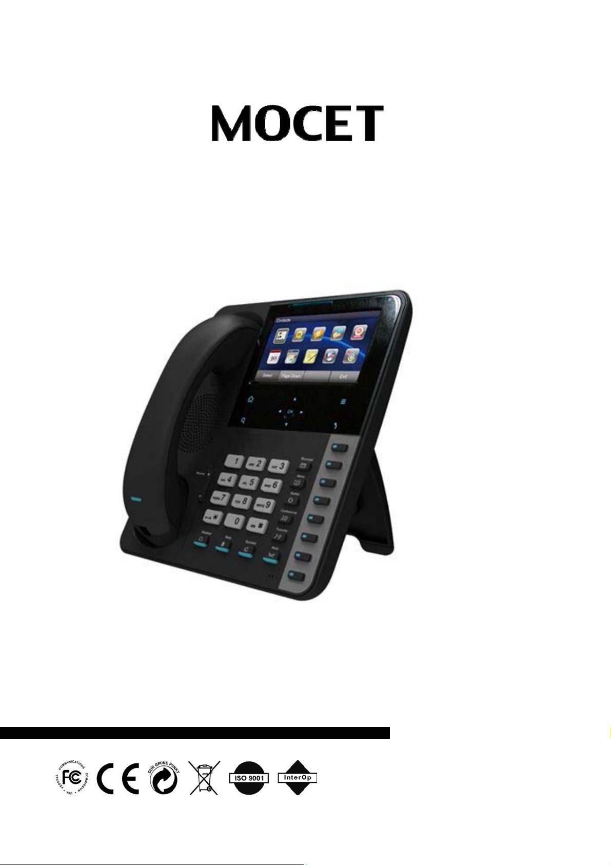
IP3072 Smart Office IP Desk Phone
User Guide
Copyright © 2012, All Rights Reserved.
Ver: A D/C: 101-0731
Page 2

MOCET IP3072 Smart Office IP Desk Phone User Guide
FCC Statement
This equipment generates, uses and can radiate radio frequency energy and, if not installed and
used in accordance with the instructions in this guide, may cause interference to radio
communications. This equipment as been tested and found to comply with the limits for a Class B
computing device pursuant to Subpart J of Part 15 of FCC rules, which are designed to provide
reasonable protection against radio interference when operated in a commercial environment.
Operation of this equipment in a residential area is likely to cause interference, in which case the
user, at is own expense, will be required to take whatever measures are necessary to correct the
interface.
CE Declaration of Conformity
This equipment complies with the requirements relating to electromagnetic compatibility, EN55022
class B for ITE and EN 50082-1. This meets the essential protection requirements of the European
Council Directive 89/336/EEC on the approximation of the laws of the Member States relating to
electromagnetic compatibility.
Environment
The phone you have purchased, as well as any used batteries must not be disposed of with
household waste. You should return these to your distributor if they are to replaced or dispose of
them in an approved recycling center.
Trademarks
Windows 98/2000/XT/NT™ and Internet Explorer™ are registered trademarks of Microsoft
Corporation. All other company, brand and product names, like Metaswitch™, Broadsoft™,
Freeswitch™ and Asterisk™ are registered trademarks of their respective owners.
WARNING!
1. Read these installation instructions carefully before connecting the IP phone to its power.
2. To reduce the risk of electric shock, do not remove the cover from the IP phone or attempt to
dismantle it. Opening or removing covers may expose you to dangerous voltage levels.
Equally, incorrect reassembly could cause electric shock on re-use of the appliance.
3. Do not expose the IP Phone to Fire, direct sunlight or excessive heat.
4. Do not expose the IP Phone to rain or moisture and do not allow it to come into contact with
water.
5. Do not install the IP phone in an environment likely to present a THREAT OF IMPACT.
6. You may clean the IP phone using a fine damp cloth. Never use solvents (such as
trichloroethylene or acetone), which may damage the phone’s plastic surface and LCD screen.
Never spray the phone with any cleaning product whatsoever.
7. Take care not to scratch the LCD screen.
8. The IP phone is designed to work in temperatures from 5oC to 40oC.
9. The IP phone must be installed at least 1 meter from radio frequency equipment, such as TVs,
radios, hi-fi or video equipment (which radiate electromagnetic fields).
10. Do not connect the LAN port to any network other than an Ethernet network.
11. Do not attempt to upgrade your IP phone in an unstable power environment. This could cause
unexpected issues.
12. Do not work on the system or connect or disconnect cables during lightning storms.
13. Children don't recognize the risks of electrical appliances. Therefore use or keep the phone
only under supervision of adults or out of the reach from children.
14. No repair can be performed by the end user, if you experience trouble with this equipment, for
repair or warranty information, please contact your supplier.
!
Page 2
Page 3

MOCET IP3072 Smart Office IP Desk Phone User Guide
Table of Contents
About this Guide.....................................................................................7
1. Introduction ......................................................................................8
1.1 Phone Features and Specifications....................................................................9
1.2 Requirements........................................................................................................9
1.3 Installation and Setup ........................................................................................10
1.3.1 Attaching the Stand to the Phone:..........................................................10
1.3.2 Detaching the Stand from the Phone:.....................................................11
1.3.3 Installation Combination Table: ..............................................................12
1.3.4 Connect the Handset and Power Adapter to the Phone: ......................13
1.3.5 Connect the Ethernet Cable: ...................................................................13
1.4 Appearance and Function Description.............................................................14
1.5 IP3072 Port Functions........................................................................................18
1.6 IP3072 LED Functions........................................................................................20
1.7 LCD Screen Indicators.......................................................................................21
1.8 Phone Status Icons ............................................................................................21
1.9 IP3072 Icon Function Description.....................................................................22
2. Getting Started ...............................................................................25
2.1 Customizing Your IP Phone from Menu ...........................................................25
2.2 Configuring Basic Settings................................................................................26
2.2.1 Volume Setting .........................................................................................26
2.2.2 LCD Brightness ........................................................................................26
2.2.3 Call Setting................................................................................................26
2.2.4 Lock Your Phone......................................................................................27
2.2.5 Speed Dialing Setting...............................................................................28
2.2.6 Reboot Your phone ..................................................................................28
2.2.7 Managing Contacts ..................................................................................29
2.2.7.1 Adding Contacts...............................................................................29
2.2.7.2 Editing Contacts ............................................................................... 30
2.2.7.3 Deleting Contacts.............................................................................30
2.2.7.4 Placing a Call to a Contact...............................................................30
Page 3Page 3
Page 4

MOCET IP3072 Smart Office IP Desk Phone User Guide
2.2.7.5 Sending a Contact to Remote user...................................................30
2.2.8 Managing Call Logs..................................................................................31
2.2.9 Viewing Your Phone’s Information .........................................................32
2.3 Configuring Advanced Settings........................................................................32
2.3.1 Configuring Programmable Keys............................................................32
2.3.2 Managing Instant Message......................................................................33
2.3.2.1 View messages: ...............................................................................33
2.3.2.2 Create a new message:....................................................................33
2.3.2.3 Delete a message:............................................................................33
2.3.2.4 Edit a Message Temp late.................................................................34
2.3.3 Managing E-mails.....................................................................................34
2.3.3.1 Setup E-mail Account.......................................................................34
2.3.3.2 Receive E-mail .................................................................................35
2.3.3.3 View received e-mail: .......................................................................35
2.3.3.4 View draft:.........................................................................................35
2.3.3.5 View sent-out e-mail:........................................................................35
2.3.3.6 Delete E-mail....................................................................................36
2.3.3.7 Create New E-mail ...........................................................................36
2.3.4 Managing Answering-Machine Messages..............................................36
2.3.5 Managing Surveillance.............................................................................37
2.3.5.1 Auto search the IP camera in the same subnet................................37
2.3.5.2 View the camera IP information........................................................37
2.3.5.3 Manual Surveillance camera setting,................................................37
2.3.6 Backlight Timeout ....................................................................................38
2.3.7 Wallpaper Setting .....................................................................................38
2.3.8 On Conditional Function..........................................................................38
2.4 Advanced Application........................................................................................39
2.4.1 Calendar....................................................................................................39
2.4.2 World Clock...............................................................................................39
Page 4
Page 5

MOCET IP3072 Smart Office IP Desk Phone User Guide
2.4.3 MemoPad...................................................................................................40
2.4.4 XML Browser.............................................................................................40
2.4.5 Multimedia Player.....................................................................................40
2.4.6 Alarm Clock...............................................................................................41
2.4.7 Painting Board..........................................................................................42
2.4.8 File Manager..............................................................................................42
2.4.9 Network Time Settings.............................................................................42
2.4.10 Door Phone Function.............................................................................43
2.4.11 Video Phone............................................................................................43
3. Using Basic Features ....................................................................45
3.1 Common Terms ..................................................................................................45
3.1.1 Lines..........................................................................................................45
3.1.2 Calls...........................................................................................................46
3.1.3 Register to a server..................................................................................46
3.1.4 Caller ID.....................................................................................................46
3.2 Installing Your IP Phone ....................................................................................47
3.3 Configuring Your IP Phone for Service ............................................................47
3.4 Line Selection .....................................................................................................47
3.5 Placing a Call ......................................................................................................47
3.6 Placing an Urgent Call........................................................................................ 48
3.7 Adjusting Call Volume........................................................................................49
3.8 Canceling a Call..................................................................................................49
3.9 Answering a Call.................................................................................................50
3.10 Answering an Urgent Call................................................................................50
3.11 Rejecting a Call.................................................................................................50
3.12 Ending/Holding/Resuming a Call ....................................................................51
3.13 Muting and Un-Muting a Call ...........................................................................52
3.14 Redialing a Number..........................................................................................52
3.15 Setting up a Conference Call...........................................................................52
3.16 Transferring a Call............................................................................................53
3.16.1 Blind Transfer.........................................................................................53
3.16.2 Semi-Attended Transfer.........................................................................53
Page 5Page 5
Page 6

MOCET IP3072 Smart Office IP Desk Phone User Guide
3.16.3 Attended Transfer...................................................................................54
3.17 Forwarding a Call..............................................................................................54
3.18 Using Voice Mail...............................................................................................54
3.19 Placing a Speed Dial Call.................................................................................55
4. Using Advanced Features.............................................................56
4.1 Login Web UI.......................................................................................................56
4.2 Changing the User’s Password.........................................................................57
4.3 Viewing Phone Information on Web User Interface.........................................57
4.4 Changing Phone Settings..................................................................................58
4.5 Using Programmable Keys................................................................................60
4.6 Changing System Settings ................................................................................64
4.7 Managing EDM....................................................................................................65
4.8 Managing Phonebook ........................................................................................66
4.8.1 Private Phonebook...................................................................................66
4.8.2 Public Phonebook ....................................................................................68
4.9 XML Web Services..............................................................................................68
5. Using Advanced Call Features.....................................................69
5.1 Call Waiting.........................................................................................................69
5.2 Intercom Call....................................................................................................... 69
5.2.1 Answering an Intercom Call ....................................................................69
5.2.2 Placing an Intercom Call..........................................................................69
6.. Using USB Accessories with Your Phone....................................70
6.1 USB Keyboard.....................................................................................................70
7. Troubleshooting.............................................................................71
8. Glossary..........................................................................................72
8.1 Acronyms............................................................................................................72
8.2 Terminology........................................................................................................73
Page 6
Page 7

MOCET IP3072 Smart Office IP Desk Phone User Guide
About this Guide
This guide explains how to use the basic features of your new IP3072 phone. Not all
features listed are available by default. Contact your system or network administrator to
find out which features and services are available to you on your system.
Your System Administrator has the ability to customize some features on this phone. For
information on more advanced settings and configurations, administrators should refer to
the IP3072 Smart Office IP Desk Phone Administrator Guide.
Page 7Page 7
Page 8

MOCET IP3072 Smart Office IP Desk Phone User Guide
1. Introduction
The MOCET IP3072 Smart Office IP Desk Phone is an Internet telephony phone that
connects to an Ethernet network rather than a traditional PSTN line. Basically, it can be
used as an extension phone in an office or stand alone phone at home. To function, it
must be registered to an IP PBX, VoIP Server or ISP/ITSP Soft switch and can deliver high
quality voice quality and perform many advanced telephony functions and PBX-equivalent
call features.
After connecting the phone to the network and successful registration to a supported SIP
server whether local or remote, users can make, receive and transfer calls over the IP
network. The IP3072 contains multiple processors to allowing it to perform multiple phone
calls and advanced music and video playback, streaming video, monitor IP surveillance
cameras, send and receive instant messages and emails, and access and display XMLbased apps and more. The power of the IP3072 improves the productivity of your workers
and increases communication efficiency and flexibility, while delivering an excellent touch
based user experience for business communications.
The IP3072 Smart Office IP Desk Phone is an easy-to-use but sophisticated desk phone
with many advanced features including support for secure calling with trusted layer
security (TLS) and Secure Real-time Transfer Protocol (SRTP), a built-in IP Security
(IPSEC) virtual private network (VPN) client. Furthermore, its audio system has been
improved not only for wide band HD(High Definition) voice call, but also with the super
wide band music play quality.
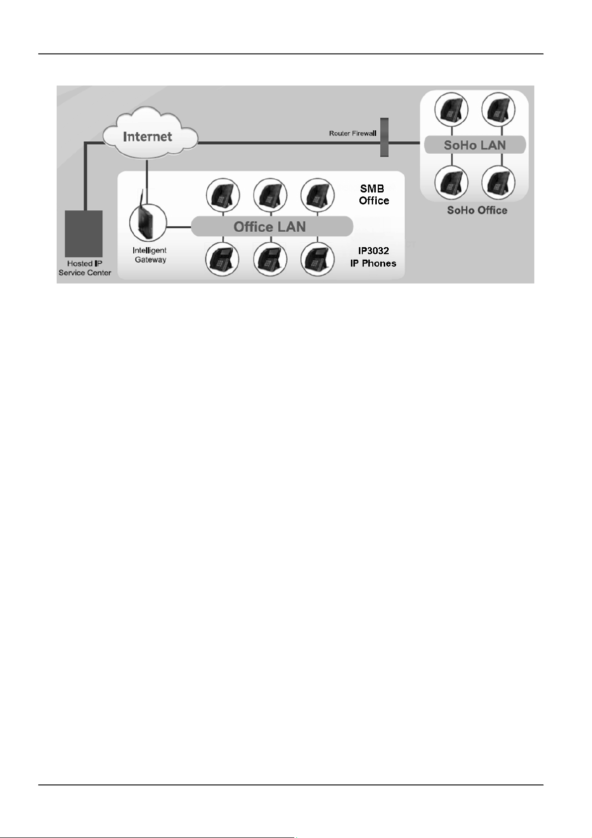
The IP3072 supports six lines and 12 call appearances to satisfy even the busiest users.
Utilizing a next generation resistive touch 4.3” LCD screen and capacitive sensitivity
control panel design, the touch-based user interface simplifies even the most complicated
calling features. The IP3072, it can be positioned with multiple tilt angles with a wall mount
option as well, has a built-in two port Gigabit Ethernet switch with Class 2 and 3 power
over Ethernet (PoE) support, and eight programable keys. The IP3072 supports local
programming through a web browser as well as local and remote auto configuration
through the MOCET auto-provisioning system and management protocols,
The IP3072 supports many supplementary features including call hold, transfer, forwarding,
3-way conferencing, WMI, CWI, music-on-hold (MOH), do not disturb (DND), and autoanswer and is compliant with industry-standard SIP protocols and many servers including
those based on Metaswitch™, Broadsoft™, Freeswitch™ and Asterisk™. Therefore, the
IP3072 can be deployed and used worldwide.
The IP3072 supports HD audio quality on both the handset, headset and speakerphones
along with support for wideband codecs including G.722. Connectivity options for the
IP3072 include, a dedicated external headset port, USB 2.0 type A port, Micro SD card slot,
and an Extended Dial Module (EDM). Up to two EDMs can be connected for a total of 56
programable buttons on the IP3072.
Page 8
Page 9
MOCET IP3072 Smart Office IP Desk Phone User Guide
1.1 Phone Features and Specifications
Complete VoIP and networking protocol support
Rich supplementary call services and phone features
HD acoustic hardware design for handset and speakerphone
G.722 wideband audio codec support
6 SIP Lines with 12 call appearances
8 programmable keys with LEDs
Interoperable with Metaswitch, Broadsoft, 3CX, Asterisk, Freeswitch and others
Auto-provisioning, remote management and security enhancements
IP camera call auto-search and video play on conditional settings
Embedded File Browser
File transfer feature
Embedded XML service browser
Embedded multimedia tools (Local video/photo viewer, music player, voice recorder)
Embedded small application tools (painting board, calendar, world clock, memo pad)
1.2 Requirements
The IP3072 IP Phone requires the following environments:
Compatible SIP-based IP PBX system or Internet-based hosted SIP service account
Ethernet/Fast Ethernet LAN (10/100 Base-T)
Page 9Page 9
Page 10
MOCET IP3072 Smart Office IP Desk Phone User Guide
1.3 Installation and Setup
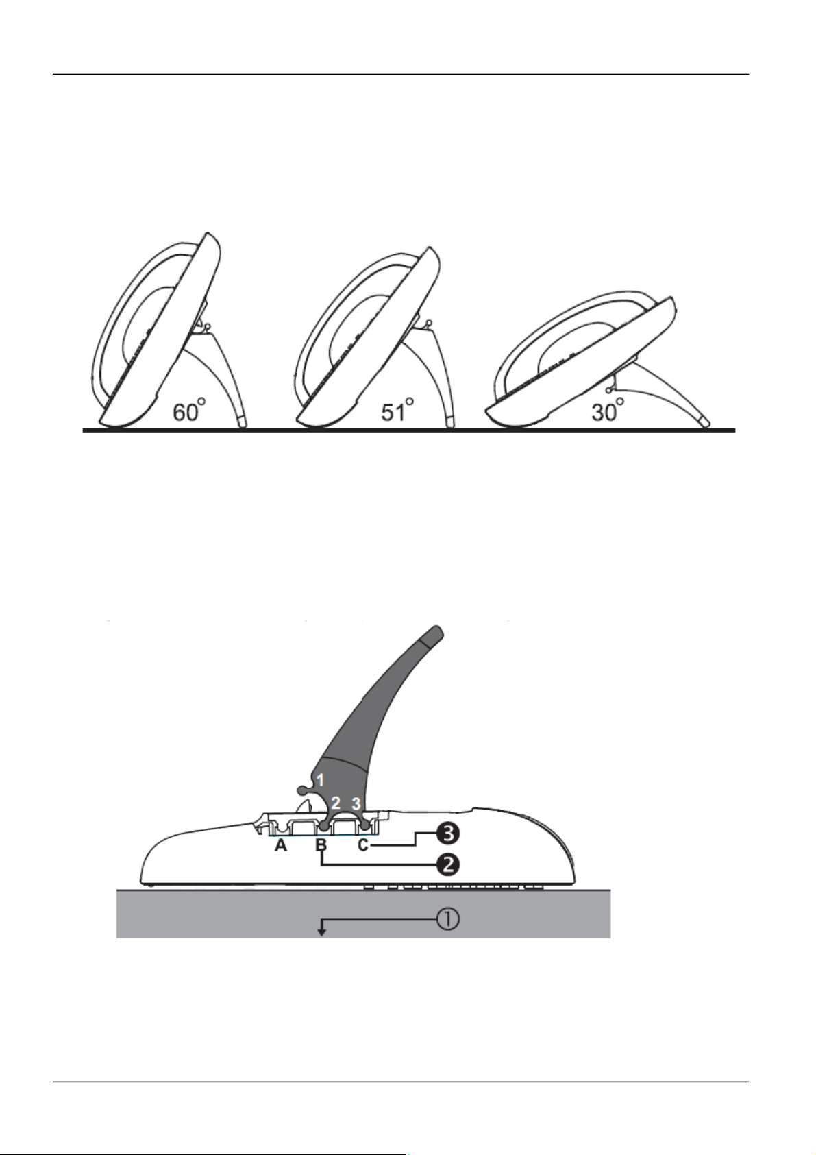
The IP3072 can support three different tilt angles of 60°, 51°, and 30° (see below).
1.3.1 Attaching the Stand to the Phone:
After unpacking the box, attach the stand to the IP3072 phone first. Below this paragraph
we illustrate an example below of 60° angle installation with the stand. There are three
sets of “antlers” on the top of the stand (named 1, 2 and 3) and there are three sets of
mounting slots on the back of the phone (named A, B and C). See the illustration below.
The procedures for attaching the stand to the phone are as follows:
Step 1: Place the main body of the IP3072 face down on your lap or a firm sofa;
Step 2: First snap the “2nd” antler into the slot “B” hole;
Page 10
Page 11

MOCET IP3072 Smart Office IP Desk Phone User Guide
Step 3: Then snap the “3rd” antler into the slot “C” hole (it may take a bit of pressure, but
when it locks in place, you will hear a click and the stand will not wiggle on the
phone.)
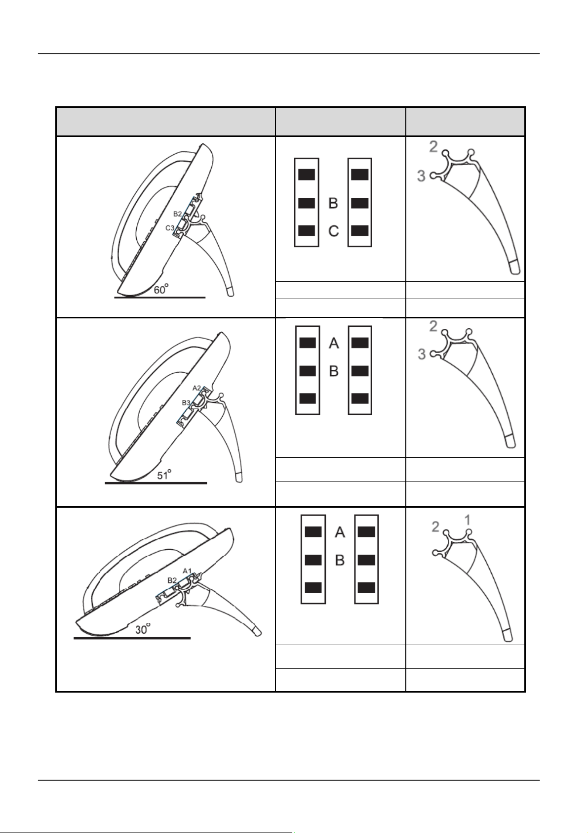
For other stand angle, such as 51° and 30°, please refer to the Installation Combination
Table below to find correct slots and correct antlers to use.
CAUTION
should be facing inward towards the phone. When a stand is installed at 60° or 30°, you
can rotate the stand between 30° and 60° quickly without pulling the antler in the slot B out.
1.3.2 Detaching the Stand from the Phone:
To remove the stand from the IP3072 phone, follow the procedures below (we are using a
60° stand as an example):
Step
Step : Press with one hand on the back of the IP phone and firmly pull the “3rd” antler
Step : Press with one hand on the back of the IP phone and firmly pull the “2nd” antler
: Place the main body of the IP phone face down in your lap or a firm sofa;
straight out of the slot “C” hole;
straight out of the slot “B” hole.
Snapping the slot “B” hole with the antler of stand first is the most
important step for a smooth installation. The product sticker on stand
Page 11Page 11
Page 12
MOCET IP3072 Smart Office IP Desk Phone User Guide
1.3.3 Installation Combination Table:
Different Tilt Angle Installation
Slot Holes
on the Back Shell
Antlers of Stand
B 2
C 3
B 3
A 2
B 2
A 1
Page 12
Page 13
MOCET IP3072 Smart Office IP Desk Phone User Guide
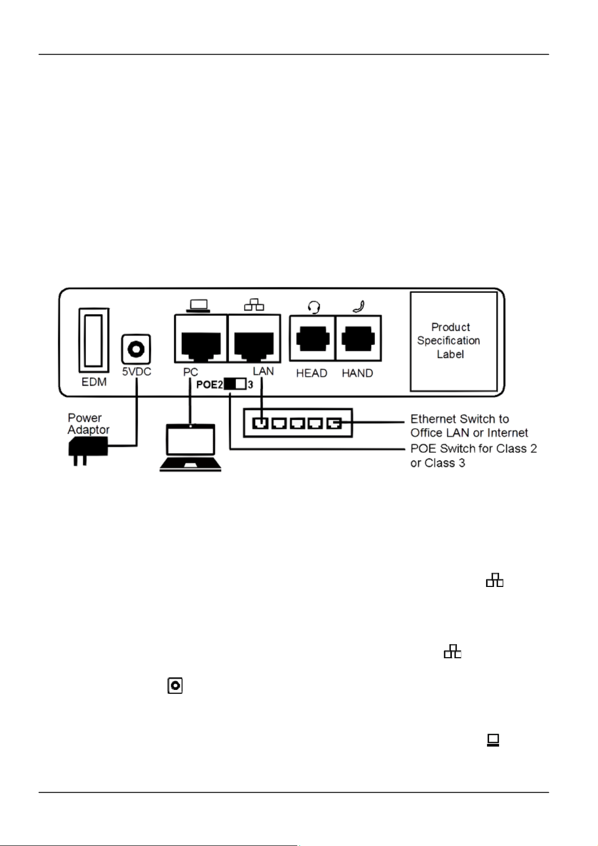
1.3.4 Connect the Handset and Power Adapter to the Phone:
After unpacking the box, connect the handset to the curly handset cord and then connect
the other end of the curly handset cord to the port marked HAND with the handset icon on
the bottom of the IP3072. Then connect the included power adapter to the port on the
bottom of the phone marked 5VDC. Please make sure you use the right power adapter. It
will have a label showing 5V and 2A. In some cases, power will be provided from your
network’s Ethernet switches and you will not need to use the included power adapter.
Please check with your network or site administrator for more details on whether your
network supports PoE. The IP3072 PoE power specification is compliant with the
IEEE802.3af with Class 2 (or 3) level. Please review the following diagram for more
assistance.
1.3.5 Connect the Ethernet Cable:
Using a general CAT-5 Ethernet cable, follow the installation steps below:
If your Ethernet Switch supports PoE:
- Please connect an Ethernet cable to the Switch port from the LAN port of the
IP3072. Then you will see the phone LEDs and buttons light up momentarily and the
phone will boot.
If your Ethernet Switch doesn’t support PoE:
- Please connect an Ethernet cable to the Switch port from LAN port of the IP3072.
Plug in the included power adaptor to the wall power outlet then plug the barrel plug to
the power port on the back of the phone. You should see the phone LEDs and
buttons light up momentarily and the phone will boot.
To eliminate the requirement for multiple Ethernet cables to a user’s location, the user’s
computer can be connected to the network through the second Ethernet port on the
IP3072.
Page 13Page 13
Page 14

MOCET IP3072 Smart Office IP Desk Phone User Guide
Notice 1: The IP3072 takes just under two minutes to start up and become operational.
There are booting screens including progress bar and text descriptions to
provide boot progress information. Please be patient.
Notice 2: If the PoE switch (on the rear panel) is set to “2” side, and the IP phone cannot
boot up through PoE Ethernet power, it may occur when accessories power
loading is over the PoE Class 2 limitation. In the case, please unplug the
Ethernet cable, and set the PoE switch (on the rear panel) is set to “3” side,
and then plug the Ethernet cable again.
The phone may crash or become malfunctional too, when if its PoE power
switch is set at class 2, and its power consumption is increased higher and get
over the class 3 range. So, please follow the same above step to change to
PoE Class 3 power level.
For your information, most Ethernet cable is carrying PoE Class 2 power. For
PoE Class 3 power, please contact your network manager or administrator for
power capability confirmation.
1.4 Appearance and Function Description
Upon unpacking the gift box, you can find the following items :
- The IP3072 IP Phone main unit
- Handset
- Curly cord for handset
- Stand foot
- Power adaptor
- Quick user guide
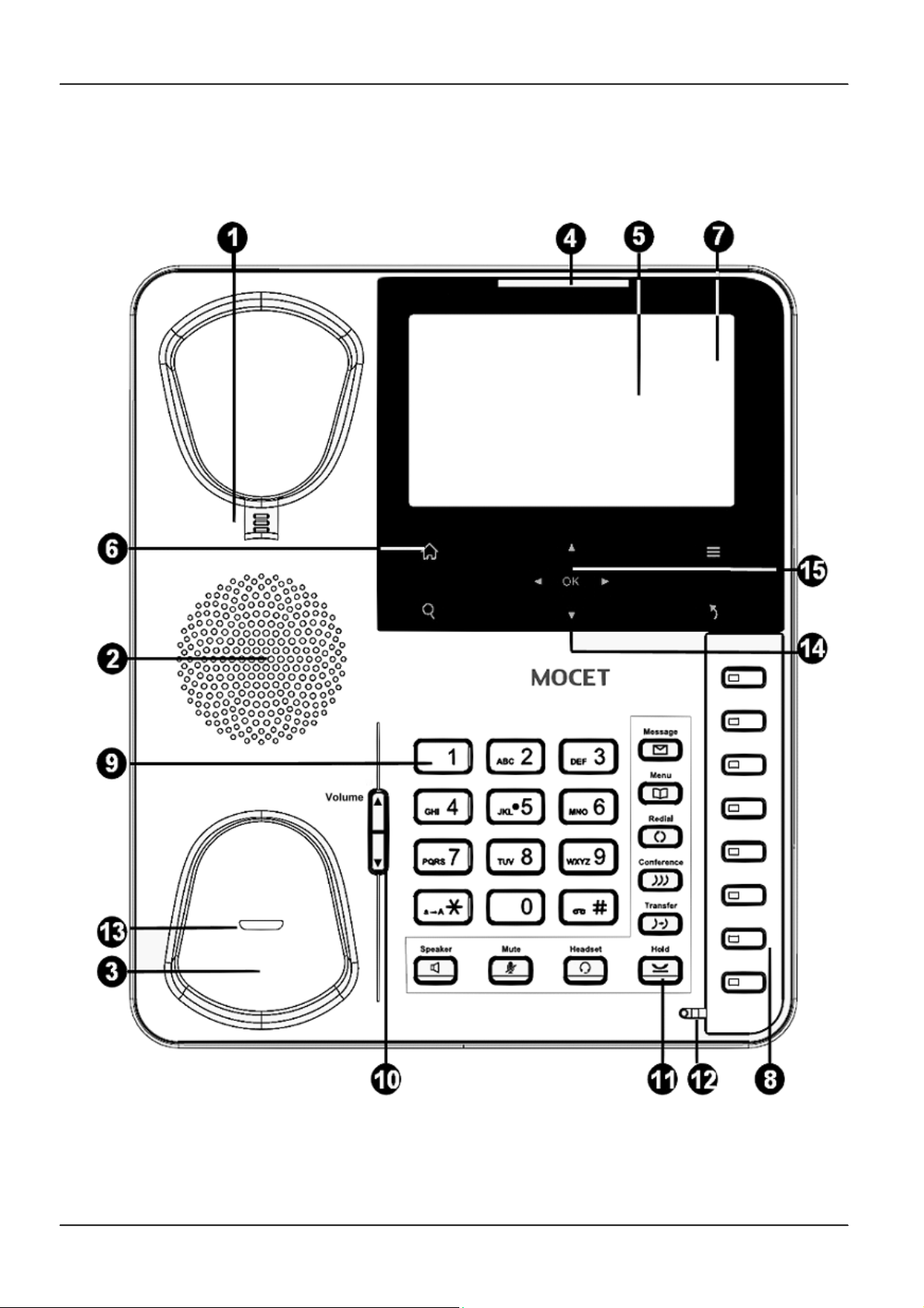
Take the IP phone main unit out and look at its appearance for understanding the
functions of different parts. The IP phone comes with a resistive touch color TFT LCD
screen with 480*272 pixels, 9 capacitive touch keys (including 5 nevigation keys), 8
programmable keys, as well as a traditional keypad, 9 function keys and volume key. And
all I/O ports are located in the rear panel. And there are several add-on accessories shown
below are available for user seperately.
- Wall mount kit
- IP-EDMX : extended dial module with 24 keys/ LEDs
- WR-211N : WiFi 11n Ethernet bridge
Page 14
Page 15
MOCET IP3072 Smart Office IP Desk Phone User Guide
The figure below illustrates the front view of the IP3072 IP Phone. With the point numbers,
you can find its name and a simple description of specified part in the following table.
Page 15Page 15
Page 16
MOCET IP3072 Smart Office IP Desk Phone User Guide
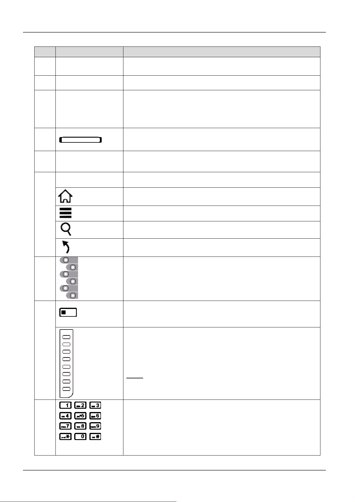
No Part Name Description
1
Hanger
2
Speaker For ring and hands-free talking.
The hanger can be pulled; it is reversed for wall-mount
installation.
Under the cradle, a hook switch is used for handset hang-on and
Hook switch &
3
Handset
bottom cradle
hang-off detection.
The handset bottom cradle is for the placement of handset;
placing the handset on the bottom cradle while on a call will end
the call.
4
Message LED
5
Color LCD Display
4 Control keys
The message LED is for message waiting indication, upgrade
alert, Instant message alert, email alert, alert for network off, and
so forth.
The LCD screen is used for displaying phone’s settings, phone
number, call status, multimedia playback and so forth.
4 sensitive touch keys used for control of the LCD screen. They
are Android like design for user easy operation.
The Home key is for returning to standby idle screen whatever
Home Key
6
Menu Key
screen phone is in.
The Menu key is for exiting from showing screen and go to main
menu page.
The Search key is for accessing XML web services if the XML
Search Key
web server is available.
The Exit key is for exiting (going back) from showing screen and
Exit Key
go to upper screen.
7
Line soft keys
8 Programmable keys
8
Programmable
key plate lable
(DESI)
9
Numeric keypad
The Line keys are located inside touch LCD screen. They are
used to indicate the currently registered lines and their status.
For operation, user can touch the specific line for call, pickup, or
other control. The line 1 is on the top place while the line 6 is on
the bottom position.
The Programmable keys are used for programming as different
hot keys by setting on menu. A blue LED is associated with each
key to indicate its status.
The programmable key plate label is plastic. For best results,
we recommend using a fine permanent marker (such as Sharpie
brand) to write on it. It can be cleaned with industrial alcohol.
Note:
Custom templates and programming software for MOCET
phones are available from DESI (see, http://labels.desi.com )
[1], [2], …, [9], [*], [0], [#]: The numeric keypad for dialing
numbers.
Page 16
Page 17
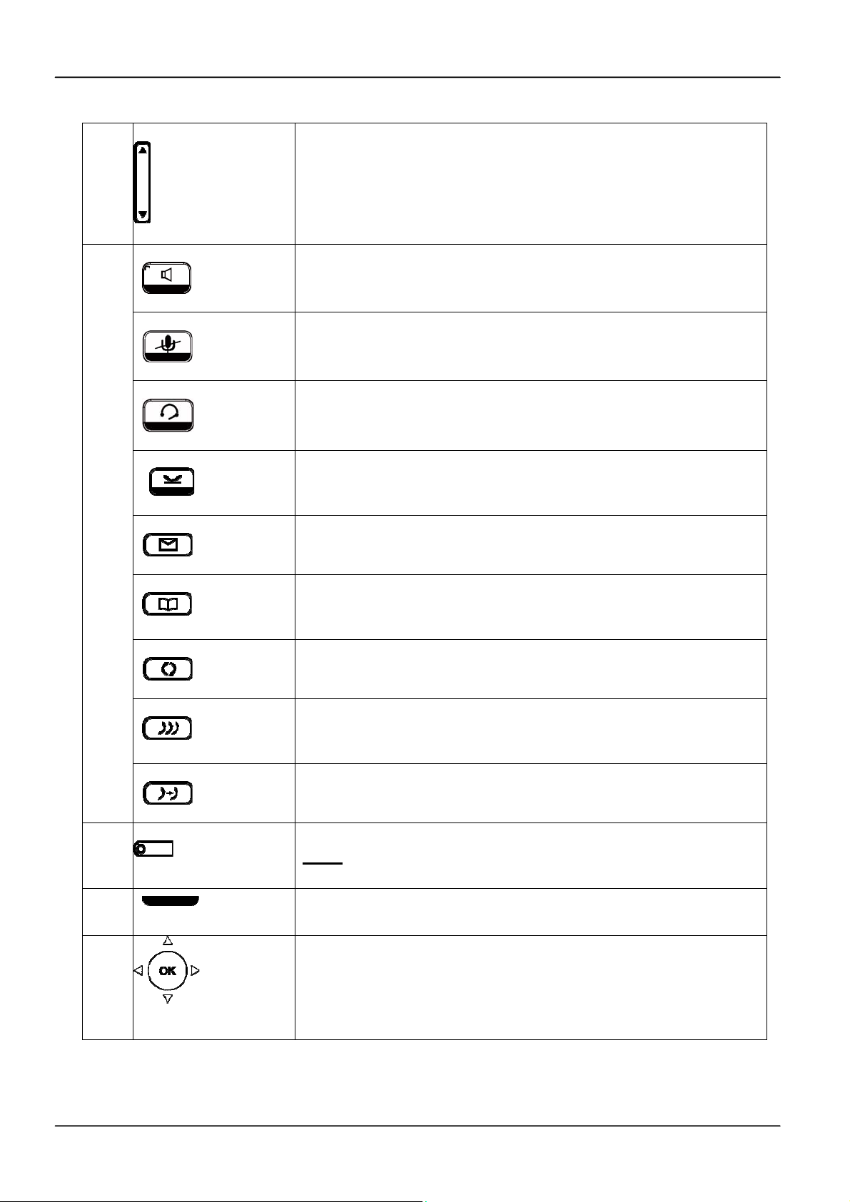
10
11
MOCET IP3072 Smart Office IP Desk Phone User Guide
Volume Key
Speaker Phone key
MUTE key
Headset key
Hold key
Message key
Phonebook key
The Volume Control key used to set the loudness of the ringer,
handset and speakerphone functions. While the phone is in idle
state, the Ringer is adjustable. While in a call, the Handset or
Speaker volume is adjustable.
The SPKR key is used to activate or deactivate the hands-free
speaker. When lit with a blue LED, the hands-free function is
operational.
The MUTE key is used to activate or deactivate the microphone.
When lit with a blue LED, the microphone is muted.
The Headset key is used to activate or deactivate the external
headset. A blue LED is lit to indicate active status.
The Hold key is used to place the active call on hold. A blue LED
is used to indicate whether the call is on hold or not.
The Message key is used to access the Voice Mail System for
message retrieval.
The Phonebook key is used to enter into the Phone Book menu
to call, add, edit or delete a contact in a selected phonebook.
Redial key
Conference key
Transfer key
12
Hands-free MIC
13
Handset LED
14
Navigation Control
keys
The Redial key dials the last dialed number automatically.
The Conference key is used to place multiple calls on the phone
into a conference on the phone.
The Transfer key is used to transfer a call to another IP phone.
Hands-free MIC hole.
You can use a paperclip to pick up the programmable key
Note:
plate label (overlay) right here.
The Handset LED. To show the phone’s status.
The Navigation Control Keys are used for navigating the menus
on the phone; menu items are displayed on the LCD screen.
Page 17Page 17
Page 18
MOCET IP3072 Smart Office IP Desk Phone User Guide
A
15
The OK button is used to confirm and save a setting on the
phone or to dial a phone number.
Navigation OK key
1.5 IP3072 Port Functions
The back side view and the connectors of the IP3072 are as follows:
No Part Name Description
1 Handset Connector RJ-9 jack for connecting handset cord.
2 Headset Connector RJ-9 jack for connecting headset cord.
RJ-45 Jack 1000/100/10Mbps Ethernet port for connecting to the
3 LAN Port
local area network (LAN). This port can support power over Ethernet
(PoE) if the LAN switch provides it.
dip switch that can be set to Class 2 (under 6.49W) or Class 3
(under 12.95W). In general case, Class 2 is enough for the IP phone.
When the conditions below:
(1) Heavy Gigabit Ethernet data transfer and playing video with
loudest speaker output (without IP-EDMX and USB dongles)
4 POE 2/3 switch
(2) General usage of phone call application but equipped with two
IP-EDMX modules. (No USB dongle attached)
(3) General usage of phone call application but equipped with one
IP-EDMX module and USB dongle that sinks power over 1 Watt.
(4) General usage of phone call application but equipped with one
USB dongle that sinks over 1.5 Watt (without IP-EDMX).
(5) Other conditions that need more power from IP phone.
5 PC Port RJ-45 Jack 100/10Mbps Ethernet port for connecting to a computer.
If an external power source is required, the adaptor is plugged in
6 Power Jack
here. Please use the power adaptor supplied in the package. The
power input specification of adaptor is DC 5V 2A.
SATA interface for attaching the Extended Dial Module (IP-EDMX)
7 EDM Port
accessory. Up to two IP-EDMX units can be supported with the
IP3072. Please refer to IP-EDMX Quick User Guide for more
information.
This Micro SD Slot can support the IP phone to access or retrieve
8 Micro SD Slot
stored data in the SD card, including music, video, phone book and
even firmware.
9 USB Port Type A
USB 1.1 port with 5V/500mA power limitation (Can be used to
connect with keyboards.)
Page 18
Page 19

MOCET IP3072 Smart Office IP Desk Phone User Guide
Please refer to the figure below for these I/O port locations on the back shell of the IP3072
phone.
Remarks: There are 2 wiring slots under the I/O ports. One is used for fit Handset cord
and the other is used to fit the power adaptor wire.
Page 19Page 19
Page 20
MOCET IP3072 Smart Office IP Desk Phone User Guide
1.6 IP3072 LED Functions
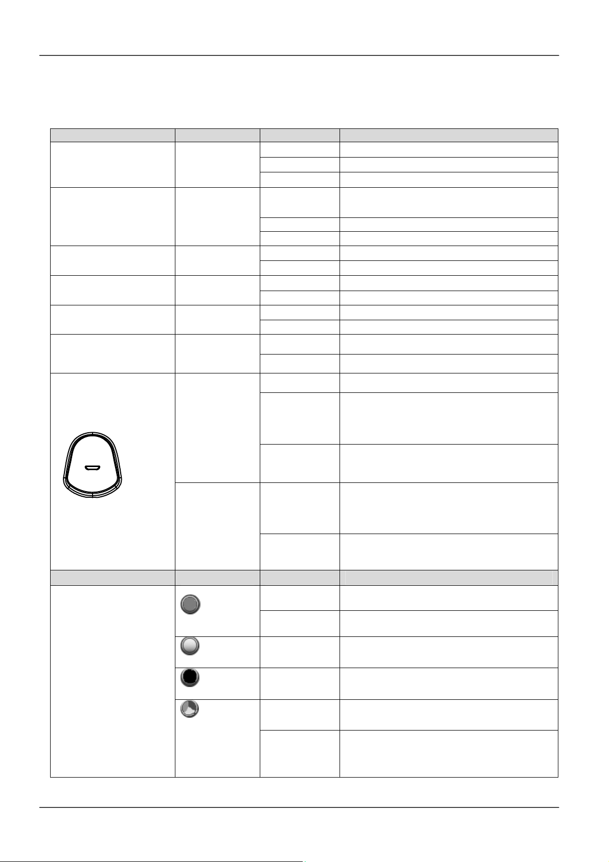
The following table describes all functions of LED indicators:
LED Color Status Description
Message LED
Programmable LED
Hold LED Blue
Speakerphone LED Blue
MUTE LED Blue
Headset LED Blue
Blue
Blue
Off No new message(s).
Steady The phone is booting or upgrading.
Blinking slow New message(s) indication.
Steady
Blinking slow Incoming call notification.
Off Feature is set “Off-inactive”.
Off No call is on hold.
Blinking slow Call is placed on hold.
Off Speakerphone is not in use.
Steady On-hook dialing or hands-free mode.
Off Microphone is active.
Steady Microphone is inactive.
Off Headset is not in use.
Steady Headset is in use.
Feature is set to “ON – Active”
or the phone is busy.
Steady The phone is booting.
The phone is upgrading or urgent call
Handset LED
Red
Flashing faster
Blinking slow
Steady
Blue
Blinking slow
notification; urgent call feature is not
available on all phone systems.
Link failure, SIP account expiration, or
SIP Server not responding.
The phone is in a normal idle state, or
is during a call with G.722 codec by
handfree or headset.
A normal incoming call with wideband
G.722 codec notification.
LED Icon on LCD Color Status Description
LCD Line Icons
Green
White
Black
Steady
Blinking slow
Steady
Steady
The line registers ok, and is in use.
The line is put on hold.
The line registers ok, and is not in use.
The line registers failed.
3 colors pie
(Green, Red,
Yellow)
Steady
Blinking slow
Page 20
The line is on a 3-way conference call.
The line is on a 3-way conference call,
but is put on hold.
Page 21

MOCET IP3072 Smart Office IP Desk Phone User Guide
1.7 LCD Screen Indicators
The following picture shows the standard LCD display. There are four touch soft keys
associated with the operation of LCD display. For different menu or status items, the
display items will change accordingly.
1.8 Phone Status Icons
The following table describes line and phone status icons on the main screen:
Top Line Icons on LCD
Network cable disconnected
IP Conflict
Missed call
Call forward
The icon indicates the network cable is disconnected
or broken.
The icon indicates the IP address of IP3072 conflicts
with other device’s.
The icon indicates IP3072 has a new missed call.
The icon indicates IP3072 is enabled “Call
Forwarding”.
Description
Auto answer (AA)
Don’t disturb (DND)
Voice mail (VM)
The icon indicates IP3072 is enabled “Auto Answer”.
The icon indicates IP3072 is enabled “Don’t Disturb”.
The icon indicates IP3072 has new voice mail(s).
And the number of new voice mail is showing in “VM
Msgs: XXX”.
Page 21Page 21
Page 22
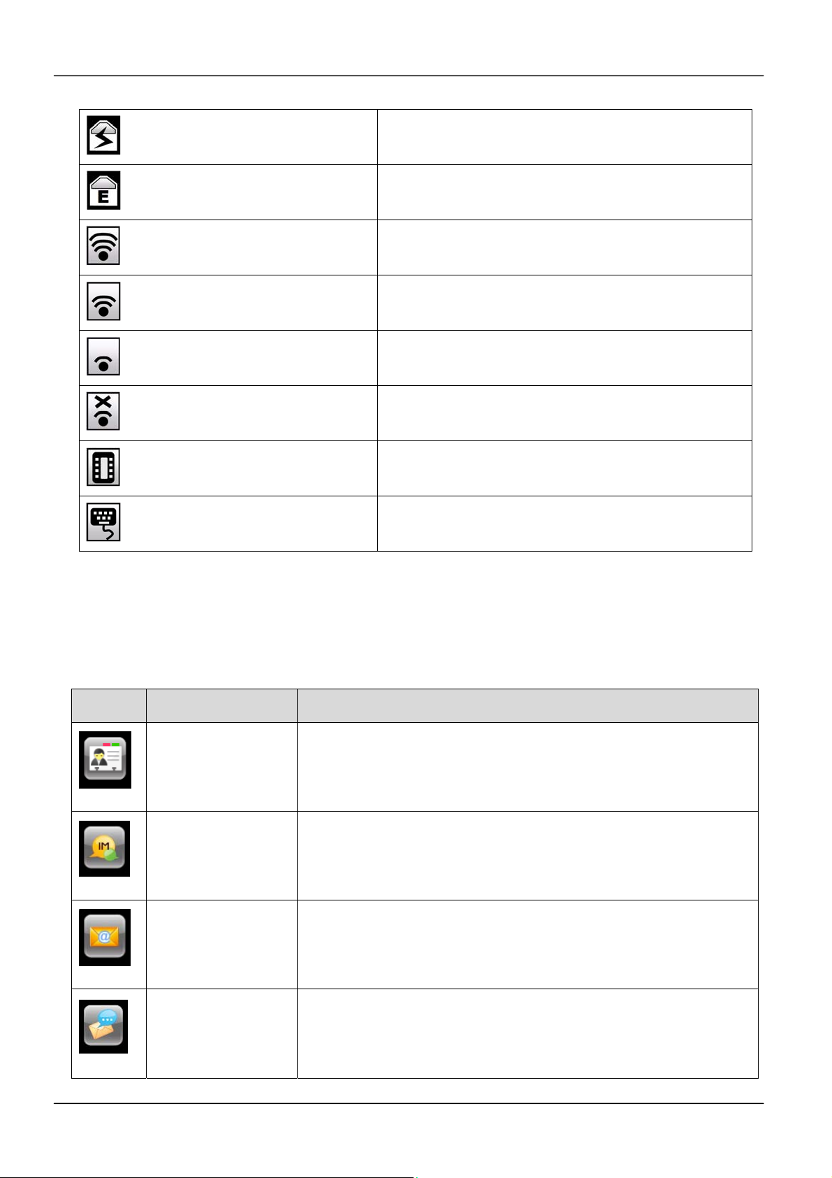
MOCET IP3072 Smart Office IP Desk Phone User Guide
Instant message (IM)
E-mail(EM)
Wireless signal is good
Wireless signal is fair
Wireless signal is poor
Wireless signal disconnected
IP-EDMX connected
USB Keyboard connected
The icon indicates IP3072 has instant message(s).
The icon indicates IP3072 has new E-mail(s).
The icon indicates IP3072 is connected to Wi-Fi
access point through Wi-Fi Ethernet bridge, and has
good signal strength.
The icon indicates IP3072 is connected to Wi-Fi
access point through Wi-Fi Ethernet bridge, and has
fair signal strength.
The icon indicates IP3072 is connected to Wi-Fi
access point through Wi-Fi Ethernet bridge, but has
poor signal strength.
The icon indicates IP3072 is not connected to Wi-Fi
access point through WR211N Wi-Fi Ethernet
bridge.
The icon indicates IP3072 is connecting with IPEDMX module(s).
The icon indicates IP3072 is connecting with an
USB Mini Keyboard.
1.9 IP3072 Icon Function Description
Below table shows all the available icons used in IP3072, their function or applications are
also described as follows:
Icons Function Name Description
Contacts
Instant
Messaging
E-mail
This is Phonebook of the IP phone. It contains public and private
contact information.
User can write, send, receive, read and delete the instant
messages through this function support. The destination can be
one phone number.
User can write, send, receive, read and delete the e-mails
through this function support. The destination can be one or more
real email addresses.
Answering
Machine
User can read and delete the voice messages through this
function support. The voice mail system is in the IP phone, but
not in the IP PBX or SIP server.
Page 22
Page 23

IP Surveillance
MOCET IP3072 Smart Office IP Desk Phone User Guide
User can configure IP address and related information of IP
Camera(s), then open the video streaming any time for the
purpose of surveillance. And IP3072 support special On-condition
control mechanism and enable users to utilize IP Cameras for
door phone or video-conferencing applications.
Calendar
World Clock
MemoPad
XML Browser
Multimedia
This is used for schedule arrangement and personal memo of
events.
The world clock supports world wide time zone information that
user can read the current time of any location. It is a very
convenient tool for users to book meeting time with multiple
location parties.
User can write down memo(s) by input texts and save into the IP
phone even during a call.
Launching this, user can connect to a target XML server and
browse its web pages. The XML server can be built in intranet or
internet as enterprise news center and bulletin board.
The multimedia is used for playing music, video and viewing
images on the IP phone. Besides, it can support digital photo
frame too. Some file formats are supported.
Alarm Clock
Painting Board
File Manager
General Setting
Tool
Administrator
Setting Tool
User can use the Alarm tool to set particular time(s) or periodic
time(s) to remind users.
The tool can be used for painting with a finger or proper pen and
then save to the storage (Micro SD card) or send to other call
party (through his/her phone number).
User can list and find the files in the storage (Micro SD card) or
embedded memory of the IP phone.
This is a user level configuration tool.
This is an advanced level configuration tool. Administrator can
enter this section with administrator password.
Page 23Page 23
Page 24
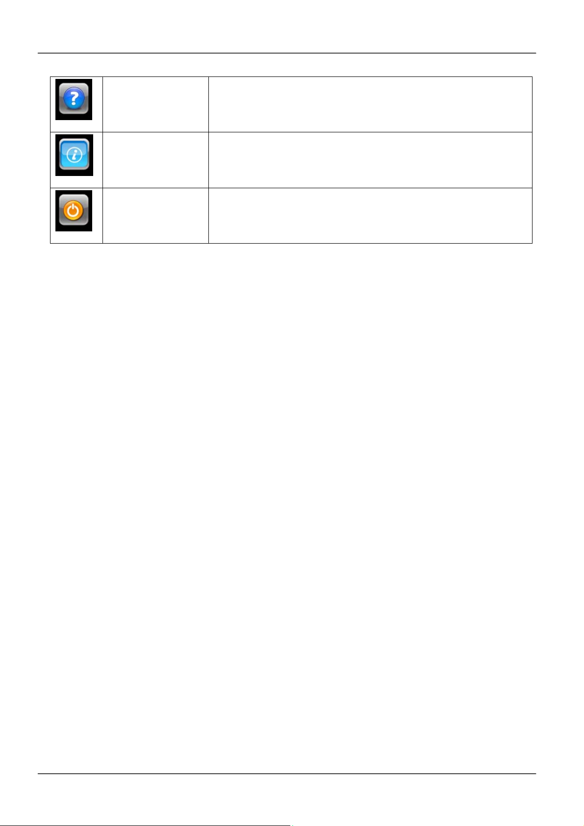
Help
MOCET IP3072 Smart Office IP Desk Phone User Guide
The help key will display some useful information to user. The
information includes Icon description, special call feature
operation brief and others.
Information
The information contains IP phone’s IP address, MAC address,
firmware version and so on.
Reboot
When the reboot is pressed, the phone will perform a warm boot
action.
Page 24
Page 25
MOCET IP3072 Smart Office IP Desk Phone User Guide
2. Getting Started
2.1 Customizing Your IP Phone from Menu
You can customize your IP phone by adjusting the settings including display contrast, ring
type, device volume adjustment, call settings, and add, edit or delete contacts in the
phonebooks of the IP3072 using the on-screen menus, buttons and navigation keys.
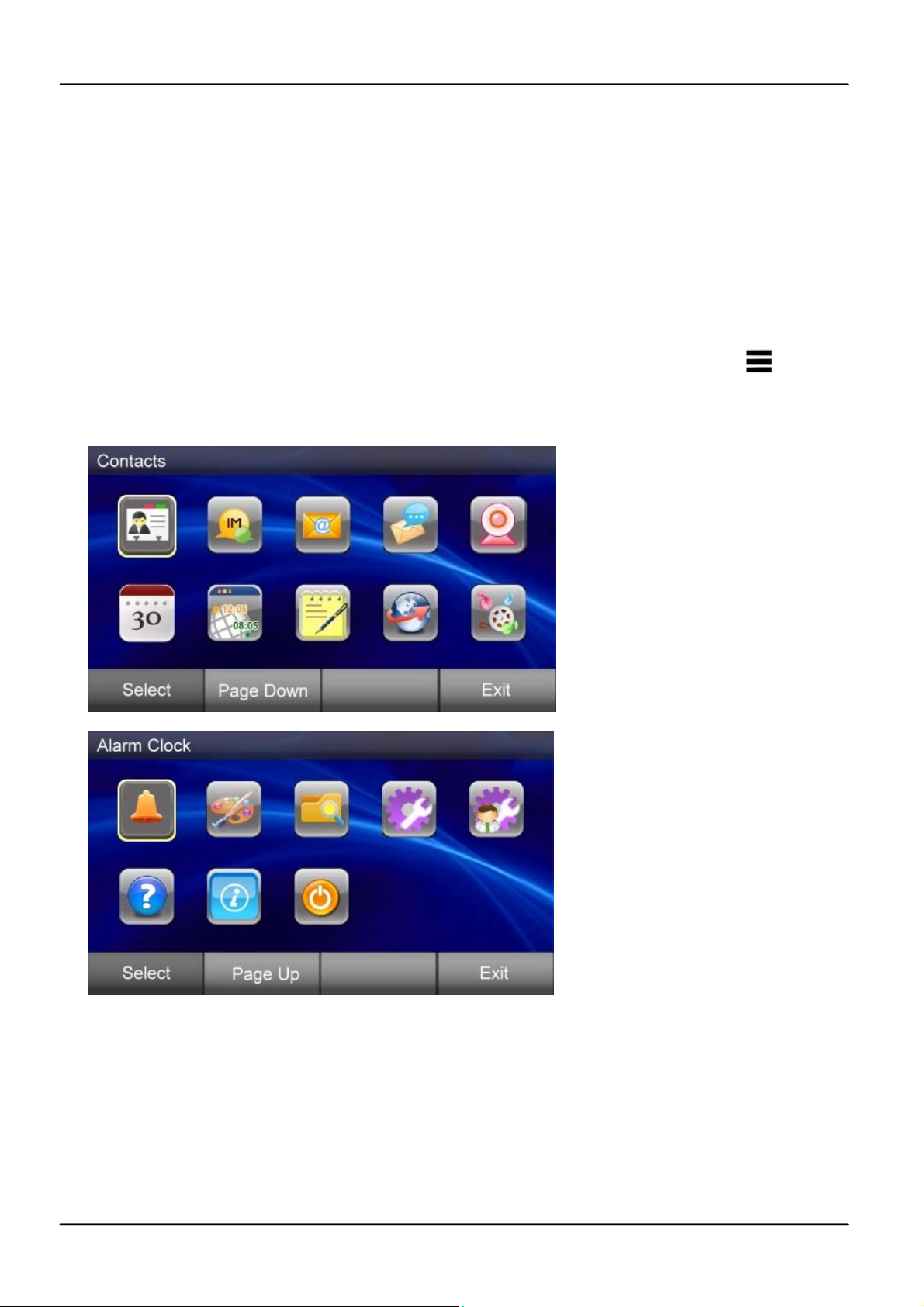
To configure your IP Phone from the menu, you can press Menu sensitive key( ) under
the LCD, the first page of menu icons will be prompted. If you press the “Page Down”
soft key, the second page will be displayed too.
You can navigate through the menu with the navigation keys. The following sections will
describe how you can setup your IP Phone through this menu. If you require additional
information or assistance with your new phone, contact your system administrator.
Page 25Page 25
Page 26
MOCET IP3072 Smart Office IP Desk Phone User Guide
2.2 Configuring Basic Settings
2.2.1 Volume Setting
You can configure following volume settings:
Hand-free speaker volume
Handset speaker volume
Headset Speaker volume
Hand-free MIC volume
Handset MIC volume
Headset MIC volume
To configure volume:
1. Press “Menu” Page Down
2. Select Settings Volume Settings. . Then select which device
volume you want to set.
3. Use the Navigation Up and Down or Left and Right keys to change the volume
levels
4. Press the Navigation OK key to confirm the change and exit volume change screen.
2.2.2 LCD Brightness
To configure the brightness of the LCD to a comfortable level:
1. Press “Menu” Page Down Settings
2. Select Display Settings Backlight Brightness
3. Press Navigation Up and Down keys to increase or decrease the display brightness
4. Press the Navigation OK key to confirm the changes and exit the menu
2.2.3 Call Setting
You can configure following call features:
Do Not Disturb (DND)
Auto Answer
Page 26
Page 27
MOCET IP3072 Smart Office IP Desk Phone User Guide
Call Waiting
Call Completion
Call Forwarding
To configure those features:
1. Press “Menu” Page Down Settings
2. Select the Call Setting , then select which feature you want to change.
3. Use the Navigation Up and Down keys to select Enable or Disable
4. Press the Navigation OK key to confirm the changes and exit the menu.
2.2.4 Lock Your Phone
Sometimes you don’t want other people to use your IP Phone. You can lock your phone
and configure a personal identification key (PIN) to unlock the phone.
To change pin number:
1. Press “Menu” Page Down Settings
2. Select Phone Lock Settings Change Pin Number
3. Input the new pin number, default is “1234”
4. Press Navigation OK key to confirm the change and exit the menu
To lock your phone:
1. Press “Menu” Page Down Settings
2. Select Phone Lock Settings
Locking Phone.
3. Key in pin number, the default is “1234”
4. Press Navigation OK key to confirm the change and exit the menu. You will see
our phone is locked.
Page 27Page 27
Page 28
MOCET IP3072 Smart Office IP Desk Phone User Guide
After phone is locked, hard key pressing and function pressing will take no effect, and can
not make outgoing call except emergency call, but answering the incoming call is allowed.
2.2.5 Speed Dialing Setting
The Speed Dialing feature let you store up to 12 phone numbers that you can access
easily using a single digit Speed Dial number from 0 to 9., *, and #.
To configure a speed dial number:
1. Press the Speed Dial soft-key below the LCD screen
2. Select the speed dial number to configure (from 0 to 9, *, #). And press the
Navigation OK or Edit soft-key to edit the setting, and enter the phone number.
3. Press the Navigation OK key to save the changes and exit the menu
In the speed dial table, you may use Edit” soft-key to modify the existed speed dial item or
use Dial soft-key to dial out the selected number:
1. Use More soft-key to Save the edition or Search the number in contact list
Use Save to save the edition during editing screen
Use Search to load a number from contact list
2. Use Dial soft-key to dial out the highlighted number
2.2.6 Reboot Your phone
Sometimes you will need to reboot your phone to apply new settings.
To reboot your phone:
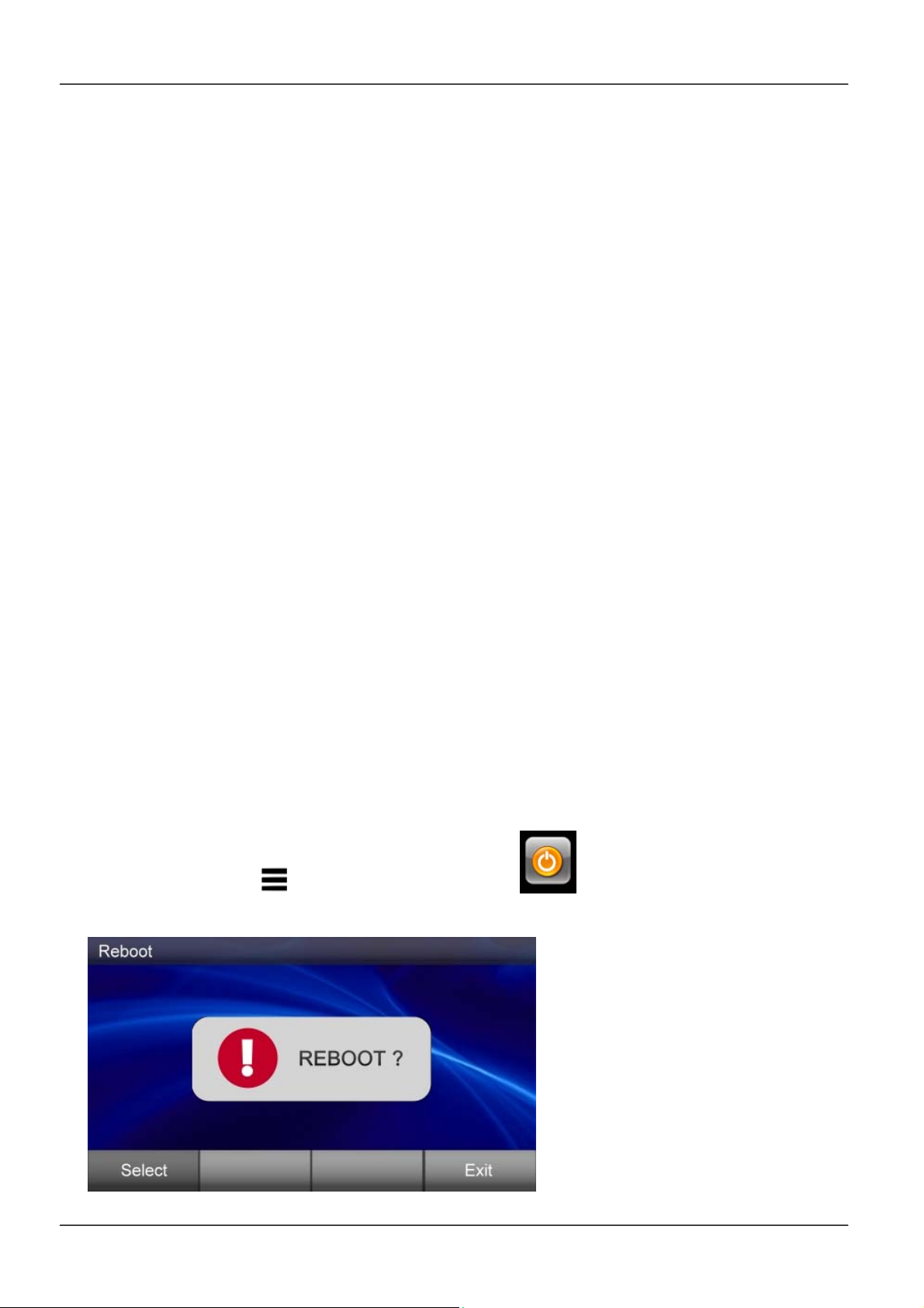
1. Press “Menu” Page Down Reboot
2. Press “Select” soft-key to reboot your phone.
Page 28
Page 29
MOCET IP3072 Smart Office IP Desk Phone User Guide
Note: The IP3072 takes about 2 minutes to start up after rebooting; there will be a series
of diagnostic lights on the phone during the process. If your phone does not become
operational within 2 minutes, contact your administrator or Service Provider support line.
2.2.7 Managing Contacts
The IP3072 supports four different contact lists:
All Contacts
LDAP Directory
Public Contacts
Private Contacts
You can store up to 100 Private Contacts in your phone’s directory, and you can add, edit,
delete, dial, or search for a contact in this directory.
Public Contacts are provided for you by the administrator or Service Provider. They can
be viewed, and used, but not changed or deleted. For more information, please contact
your administrator or Service Provider.
The IP3072 can also access a local or remote LDAP Directory. Please contact your
administrator or Service Provider for more information on how to enable, configure or
access this feature.
The All Contacts lets you search and dial a contact from all the configured contacts
databases.
There are 2 ways to enter your phone’s directory:
1. Press the “Phone book” hot key.
2. Press “Menu”
Contacts
2.2.7.1AddingContacts
To add a new contact:
1. Go to the Contacts Private.
2. Press the Add soft-key.
3. Enter “Name”, “Number”, “Mobile No.”, “Home No.”, “Email”, “Group”, “Ring Tone”,
“Gender”, “Title”, “Department”, “Company”, “Location”, “Address”, “Web URL”
from the key pad.
Page 29Page 29
Page 30

MOCET IP3072 Smart Office IP Desk Phone User Guide
4. Press the Save soft-key when you are finished
2.2.7.2EditingContacts
To edit your contact:
1. Use the Navigation Up and Down keys to select the contact your want to edit.
2. Press the Details soft key to display the selected contact details
3. Use the Navigation Up and Down keys to select the fields you want to change.
4. Press the Edit soft key to modify the data in the selected field.
5. When finished making changes, press the Save soft-key to save the changes.
2.2.7.3DeletingContacts
To delete your contact:
1. Use the Navigation Up and Down keys to select the contact your want to delete.
2. Press Details soft-key to display the selected contact details
3. Press Delete soft-key to delete the selected contact
4. The contact is deleted from the directory.
2.2.7.4PlacingaCalltoaContact
To dial from a directory:
1. Navigate to a contact (private, public or LDAP).
2. Use the Navigation Up and Down keys to select the number your want to dial.
3. Press Details soft-key to display the selected contact details
4. Use the Navigation Up and Down keys to select Number
5. Press Dial soft-key.
6. The phone will dial the number selected.
2.2.7.5SendingaContacttoRemoteuser
You may send contact information to a phone user at remote side via IP3072 built-in
Instant Message.
To send the contact item:
1. Use the Navigation Up and Down keys to select the contact your want to send.
2. Press Details soft-key.
3. Use the Navigation Up and Down keys to focus on any filed except phone number.
Page 30
Page 31
MOCET IP3072 Smart Office IP Desk Phone User Guide
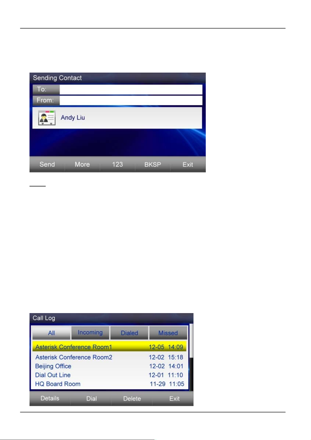
4. Press Send soft-key to construct an IM, then enther the targets of “To” and “From”
5. Press Send soft-key to sent out the contact to the remote party
Note:
This function needs special SIP server which supports SIP SIMPLE Instant
Messaging. If the contact sending is not OK, please contact your administrator or Service
Provider support line
2.2.8 Managing Call Logs
In the IP3072, there three call logs:
Dialed Calls
Missed Calls
Incoming Calls
The call logs save the last 30 numbers dialed, missed or answered. An example of the
All Calls Log is listed as follows:
Page 31Page 31
Page 32

MOCET IP3072 Smart Office IP Desk Phone User Guide
From the call log lists, you can view, delete, and dial.
To manage the selected call log:
Use the Dial soft-key to redial the call.
Use the Delete soft-key to delete the selected item.
Use the Details soft-key to view information of the call, including call time, call type,
call duration, remote number’s mobile number, home number, email.
Use the Delete All soft-key to delete all the items under current directory, such as, if
focus is “Incoming”, it will delete all the incoming call logs.
Use the Save soft-key to edit and save a call log item to the contact list.
2.2.9 Viewing Your Phone’s Information
Using the menu of the IP3072, you can check the IP3072 hardware version, firmware
version, and network status.
To view this information:
1. Press “Menu” Page Down Information
2. Use the Navigation Up and Down keys to view the information.
2.3 Configuring Advanced Settings
2.3.1 Configuring Programmable Keys
The IP3072 has 8 programmable keys, which can be configured for speed dial numbers,
phone system features like park, pickup and paging, or to monitor other extensions using
busy lamp field (BLF) notifications. From the Menu, you can view the settings for each
key. For detailed programmable key’s configuration, please refer to section 4.5 Using
Programmable Keys.
To see the setting status:
1. Press “Menu” Page Down Settings
2. Press Key Settings
3. Select the FUNC1-FUNC8 to see their settings.
Page 32
Page 33
MOCET IP3072 Smart Office IP Desk Phone User Guide
2.3.2 Managing Instant Message
The IP3072 supports SIP SIMPLE Instant Messaging (IM). With a supported service or
server, such as Ondo, Partysip, Asterisk (in-session mode), and any SIP proxy or PBX that
can forward SIP MESSAGE requests, you can send and receive messages right from your
phone using the on-screen dialpad; there is also a way to configure some useful Message
Templates, which are pre-made messages for common requests or responses, to simplify
use of IM on the IP3072.
There is a message icon and a popup message on the LCD screen when there is a new
message received.
2.3.2.1Viewmessages:
1. Press the Navigation Left or Right key to focus to “Read”.
2. Press Navigation OK key to immediately read the message.
3. The message is listed for you to view.
Or
1. Press “Menu” or press Messaging soft key.
2. Select Instant Messaging Inbox.
3. All the incoming messages are listed for you to view.
2.3.2.2Createanewmessage:
1. Press “Menu” or press Messaging soft key.
2. Select Instant Messaging Creating Message.
3. Enter “To”, ”From”, and message body, from the key pad.
4. Press Send to send the created message.
2.3.2.3Deleteamessage:
1. Press “Menu” or press Messaging soft key.
Page 33Page 33
Page 34
MOCET IP3072 Smart Office IP Desk Phone User Guide
2. Select Instant Messaging Inbox.
3. Press Delete to delete the message.
Or
1. Press “Menu” or press Messaging soft key.
2. Select Instant Messaging Clearing Messages.
3. Select Clearing Inbox Messages, Clearing Outbox Messages, or Clearing All
Messages.
2.3.2.4EditaMessageTemplate
1. Press “Menu” or press Messaging soft key.
2. Select Instant Messaging Text Templates.
3. Use the Navigation Up and Down keys to focus the item you want to edit,
4. Press Navigation OK to access edit page
5. After edition is finished, press Navigation OK key to save it
The IP3072 can save and use up to 30 Message Templates.
2.3.3 Managing E-mails
The IP3072 supports E-mail function. You can use E-mail function to send and receive
emails. To use E-mail, the IP3072 must register to an email server. Please contact your
system administrator to get an available email account.
2.3.3.1SetupEmailAccount
1. Press “Menu” Page Down Settings
2. Select E-mail Account .
Page 34
Page 35
MOCET IP3072 Smart Office IP Desk Phone User Guide
3. Enter “User Name”, “Email Address”, “Login Account”, “Login Password”, “POP3
Server Address”, “POP3 Server Port”, “SMTP Server Address”, “SMTP Server
Port” to build an email account
4. Press Test to check whether the e-mail account is valid. If it is valid and usable, you
can receive a test email from this account itself.
2.3.3.2ReceiveEmail
1. Press “Menu” or press Messaging soft key.
2. Select E-mail Receiving E-mail.
- If there is error when receiving e-mail, a pop up window will display “Receive
Email...Failed”.
- If it is successful, popup window will display “Receive Email...Successful”.
3. Press Navigation OK to close pop up window.
2.3.3.3Viewreceivedemail:
1. Press “Menu” or press Messaging soft key.
2. Select E-mail Inbox.
2.3.3.4Viewdraft:
1. Press “Menu” or press Messaging soft key.
2. Select E-mail Draft.
2.3.3.5Viewsentoutemail:
1. Press “Menu” or press Messaging soft key.
2. Select E-mail Outbox.
Page 35Page 35
Page 36
MOCET IP3072 Smart Office IP Desk Phone User Guide
2.3.3.6DeleteEmail
Use Delete soft key to delete an e-mail
Or
1. Press “Menu” or press Messaging soft key.
2. Select E-mail Clearing E-mails
3. Select “Clearing Inbox E-mails”, “Clearing Outbox E-mails”, or “Clearing Draft E-
mails”
2.3.3.7CreateNewEmail
1. Press “Menu” or press Messaging soft key.
2. Select E-mail Writing E-mail
3. Enter “To:”, “Cc:”, “Subject:” and email body from keypad
4. Press More soft-key Send to send the e-mail
2.3.4 Managing Answering-Machine Messages
The IP3072 supports local answering machine. You can forward the incoming call to the
local answering machine, thus the caller can leave a voice message to you if you haven’t
received the call.
To view the messages, you can:
1. Press “Menu” or press Messaging soft key.
2. Select Answering Machine Voice Messages.
3. All the messages are listed for you to view.
You can record a greeting message for the local answering machine. To record the
greeting:
1. Press “Menu” or press Messaging soft key.
Page 36
Page 37
MOCET IP3072 Smart Office IP Desk Phone User Guide
2. Select Answering Machine Recording Greeting.
2.3.5 Managing Surveillance
By connecting to external specific IP cametas, IP3027 can support Surveillance
application. You can view and capture video str eaming sent from the specific IP camera.
To use Surveillance application, please contact your system administrator to obtain IP
Camera information.
2.3.5.1AutosearchtheIPcamerainthesamesubnet.
1. Press Applications soft-key Select Surveillance
or Press Menu Select Surveillance
2. Available IP cameras in the same subnet will be listed on the screen
2.3.5.2ViewthecameraIPinformation
In the Surveillance page, you may use Details soft-key to view the camera IP information,
including location, IP address, login name, login password, connection mode, web
port., RTSP port, RTSP path.
2.3.5.3ManualSurveillancecamerasetting,
1. Press “Menu” Page Down Settings
2. Select Surveillance Settings
3. Use Add soft-key to add new camera item
Use Edit soft-key to edit focused item
Use Delete soft-key to delete the item
Use Save soft-key to save the edition
Page 37Page 37
Page 38
MOCET IP3072 Smart Office IP Desk Phone User Guide
2.3.6 Backlight Timeout
1. Press “Menu” Page Down Settings
2. Select Display Settings Backlight Timeout
3. Select the timeout time Press Save soft-key to save the timeout setting
2.3.7 Wallpaper Setting
1. Press “Menu” Page Down Settings
2. Select Display Settings Wallpaper Setting
3. To custom wall paper, select User-Defined Wallpaper, then in the file manager,
select a preferred wallpaper file to take effect.
2.3.8 On Conditional Function
On-condition function is for advanced call features. You can make different settings for
different call conditions. For example, when you do not want to be disturbed by someone,
you can make a setting as below.
1. Select Do not disturb in the Create Conditions from Templates.
2. Select Condition List, you will see Do not disturb.
3. Press the Edit soft key to make further settings for Do not disturb.
4. Press the Select soft key, and then press the Next soft key.
5. The Trigger List screen shows up.
6. Select When a call incoming.
7. The Condition List screen shows up.
8. Select Condition1.
9. The Parameter Selection screen shows up.
10. Press the Select soft key.
11. The Value Input screen shows up.
12. Enter the phone number of someone you do not want to be disturbed, and then press
the Select soft key to confirm.
Page 38
Page 39
MOCET IP3072 Smart Office IP Desk Phone User Guide
13. Press the Next soft key.
14. The Action List screen shows up.
15. You can select Reject a call.
16. The Parameter for Action screen shows up.
17. For Reject a call option, you do not need to input any parameter, so just press the Exit
soft key to return to the On-condition Setting screen.
To create new OCT,
1. Press “Menu” Page Down Settings
2. Select On-Condition Settings Creating New Conditions
3. Press Menu->Settings
2.4 Advanced Application
2.4.1 Calendar
Press “Menu” Calendar to access calendar application.
Press New to create a new appointment attached with focused date
Press View to view all the appointments attached with focused date
Press Edit to edit item of appointment
Press Save to save the modification of appointment
2.4.2 World Clock
Press “Menu” World Clock to access world clock application.
Press Bookmarks to view all the bookmarks.
Press MainCity to view all the main cities of all the zones.
Press Bookmarks+ to add a new bookmark.
Press Remove to remove focused bookmark item
On the screen of main city list, you can search some city you wanted by pressing digital
keys matched with a city name.
Page 39Page 39
Page 40
MOCET IP3072 Smart Office IP Desk Phone User Guide
For example, if you want to find “Beijing”,
1. Double press “2”, It will show the city list with heading letter “B” or “b”
2. Double press “3”, it will show the city list with second letter “E” or “e”
3. Press “4” for three times quickly, it will show the city list with third letter “I” or “i”
4. Press “5”, it will show the city list with third letter “J” or “j”, for the main city list only
includes one item whose first 4 letters are “Beij”, so the list shows only one item
“Beijing”.
2.4.3 MemoPad
Press “Menu” Memopad to access memoPad Application.
Press Add to add a new memopad item
Press Save to save the input during memo create screen
Press Details to view focused items, including subject and body text.
Press Edit to edit the memo.
Press Delete to delete the memo.
2.4.4 XML Browser
Please refer to administrator guide to see how to setup XML server and how to use the
service in XML browser provided by XML server.
2.4.5 Multimedia Player
Press “Menu” Multimedia to access multimedia application.
The multimedia application includes video viewer , music player , photo
viewer and voice recorder .
The soft-key functions used in video viewer and music player are listed below:
Press volume up/down key to adjust the volume of playing audio.
Press Play to play the video file
Press Pause to pause the video.
Page 40
Page 41
MOCET IP3072 Smart Office IP Desk Phone User Guide
Press Repeat to play the multimedia file again.
Press UP or Down to select next or previous file.
Press Backward or Forward to jump the playing step.
Press Once to stop playing the music without repeat.
Press Repeat All to repeatedly play all the music files one by one
Press Repeat to only repeatedly play focused music file.
Press Stop to stop the music.
For photo viewer application,
Press Open to open focused picture file
Press Play to display the play a music
Press UP or Down to select next or previous picture file.
For voice recorder application,
Press to record new file.
Press to pause recording.
Press to stop recording.
Press Files to view all the recorded files.
Press Play to play the record file
Press Delete to delete the record file
Press More to select “Copy” or “Send”
Press “Copy” to copy the file to SD card
Press “Send” to send the file to remote.
2.4.6 Alarm Clock
Press “Menu” Page Down Alarm Clock to access alarm application.
Press Edit to edit the alarm item, including alarm status(on or off), alarm time, repeat
mode (Every day or Off), alarm tone type, and note.
Press Save to save the modification.
Press Snooze to pause alarm ring and wait about 5 minutes, the alarm will ring again.
Press Dismiss to stop alarm ring.
Page 41Page 41
Page 42
MOCET IP3072 Smart Office IP Desk Phone User Guide
2.4.7 Painting Board
Press “Menu” Page Down Painting Board to access painting
application.
Use Color&Font to choose painting color(red, yellow, blue, green) and font.
Use Color&Font again to hide the color and font selecting panel.
Use More to select “Insert Text”, “Insert Photo”, and “SendFile”.
Use “Insert Text” to insert a text string to the designated position of painting board.
Use “Insert Photo” to insert a photo from photo list to central of painting board.
Use “Send File” to save the painting board to a file and send the file to remote.
Use “Save” to save the painting as picture.
2.4.8 File Manager
Press “Menu” Page Down File Manager to access file manager to
browser files in embedded memory and SD card.
Use More to select “Back”, “Copy”, “Delete”, “Send File”, and “save as custom ring”
if focused file is music file, “Save as Wallpaper” if focused file is picture file.
Use “Back” to return to upper directory.
Use “Copy” to copy the file or directory to another file system disk(embedded memory
or SD card).
Use “Delete” to delete the file or directory.
Use “Send File” to send the file to remote.
Use “Save ad custom ring” to save the music file as custom ring.
Use “Format” to format the selected disk drive.
Use “Save as Wallpaper” to save the picture file as wall paper.
2.4.9 Network Time Settings
To configure time zone, enable or disable DST(daylight saving time), DST start
Month/Day/Time, DST end Month/Day/Time, DST saving time type, you may:
1. Press “Menu” Page Down Settings
Page 42
Page 43
MOCET IP3072 Smart Office IP Desk Phone User Guide
2. Select Display Settings Date and Time Settings,
If Auto DST is enabled, DST saving type, DST start Month/Day/Time and DST end
Month/Day/Time are automatically adjusted according to time zone setting.
2.4.10 Door Phone Function
Press “Menu” Page Down Settings Select Door Phone
When a visitor makes a call from the door phone to the office phone, the office phone will
display video streaming from the IP camera as soon as it receives an incoming call from
the door phone. You can decide to pick up the call or reject the call after you see who is
calling.
To use this function, please make all required configuration ready, and enable door phone
function.
All required configuration includes:
Phone Number: Enter the phone number of the door phone.
Cam IP Address: Enter the IP address of the IP camera.
Cam Web Port: Enter the web port of the IP camera.
Login Name: Enter the login name of the IP camera.
Login Password: Enter the password of the IP camera.
2.4.11 Video Phone
Press “Menu” Page Down Settings Select Video Phone
You make a call to your colleague. Your IP Phone will display the video streaming from the
IP camera aside your colleague’s IP Phone as soon as your colleague picks up your call.
In the meanwhile, your colleague’s IP Phone will display the video streaming from the IP
camera aside your IP Phone.
To use this function, please make all required configuration ready on both your phone and
your colleague’s phone, and enable video phone function on both phones.
All required configuration on your phone includes:
Phone Number: Enter your colleague’s phone number.
Page 43Page 43
Page 44

MOCET IP3072 Smart Office IP Desk Phone User Guide
Cam IP Address: Enter the IP address of the IP camera aside your colleague.
Cam Web Port: Enter the web port of the IP camera aside your colleague.
Login Name: Enter the login name of the IP camera aside your colleague.
Login Password: Enter the password of the IP camera aside your colleague.
All required configuration on your colleague’s phone includes:
Phone Number: Enter your phone number.
Cam IP Address: Enter the IP address of the IP camera aside you.
Cam Web Port: Enter the web port of the IP camera aside you.
Login Name: Enter the login name of the IP camera aside you.
Login Password: Enter the password of the IP camera aside you.
Page 44
Page 45

MOCET IP3072 Smart Office IP Desk Phone User Guide
3. Using Basic Features
The IP3072 Smart Office IP Desk Phone is designed to be used like a regular phone on a
public switched telephone network (PSTN). You can place calls, transfer a call to someone
else, or conduct a conference call.
The IP3072 supports up to 10 simultaneous calls. However, only one of these calls can be
active at a time. The active call is the one you are using to speak or listen to. The
inactive calls can be:
On hold
Joined in a conference (with up to 3 callers)
“Incoming call” or “Ringing”
This chapter provides basic operating instructions for the phone including:
Placing a Call
Placing an urgent call
Answering a Call
Answering an urgent call
Ending a Call
Redialing a Number
Putting a Call on Hold
Setting Up a Conference
Transferring a Call
Forwarding Calls
Enabling or Disabling Do Not Disturb
3.1 Common Terms
To use the IP3072, you need to follow some conventions that we will mention in this guide.
In the following descriptions, we will introduce some common terms for your understanding.
3.1.1 Lines
A “Line” in this guide represents how many phone numbers supported in one phone. For
example, the IP3072 can support up to 6 lines configured for the same or different service
Page 45Page 45
Page 46

MOCET IP3072 Smart Office IP Desk Phone User Guide
providers or servers and even make up to 10 concurrent calls. Therefore, the IP3072 is
said to support multiple line appearances.
3.1.2 Calls
A “Call” in this guide represents how many simultaneous connections can be made to a
single phone number. Each line of service in the IP3072 can support multi calls
simultaneously. This allows the user to place one caller on hold and talk to the other
person in another call on the same Line. Therefore, the IP3072 phone is said to support
multiple call appearances.
3.1.3 Register to a server
The IP3072 must be configured before it can perform some basic functions. Although the
phone can make a peer-to-peer SIP call by dialing the other user’s IP address (i.e.,
192.168.0.12) directly on the keypad, this is inconvenient and it is hard to remember all the
IP addresses of phones on the system. This is why a hosted SIP server or local IP PBX
implements a Registrar service, which allows the connected phones to find and dial each
other more easily by extension numbers or names instead of IP addresses.
In addition, the hosted SIP server or IP PBX helps keep track of active phones, their IP
addresses for routing calls, as well as keeping track of which phones are busy or idle.
Most hosted SIP services and IP PBXs support direct system service (DSS) as well as
showing the busy lamp field (BLF) status of system phones. These allow you to directly
dial another extension and can show you whether the other phone is on a call or not.
Usually, the hosted SIP service or IP PBX will also use the Registrar service to send
messages to your phone to alert you that you have voicemail. This is called message
waiting indication (MWI).
Please refer to Configuration through Menus or Configuration through Web for detail
information of how to configure the phone to register to server.
3.1.4 Caller ID
When you receive a call, the caller's phone number is shown on the screen, if the caller
has not chosen to hide his number and if the network supports the Caller ID feature. The
IP Phone can display both the Caller ID (CLID) and the Caller Name (CNAM) of the caller
if it is available. Not all services and servers support CLID and CNAM. For more
information about this topic, please contact your service provider or system administrator.
Page 46
Page 47

MOCET IP3072 Smart Office IP Desk Phone User Guide
3.2 Installing Your IP Phone
Before placing the phone into operation, either you or your administrator or Service
Provider has to install the phone on your network. Please contact your administrator or
Service Provider for more details, or refer to the included hardware installation guide.
3.3 Configuring Your IP Phone for Service
The IP3072 must be configured for the hosted SIP service or IP PBX before operation.
The phone is usually pre-configured by the administrator or hosted SIP service provider.
For an advanced or experienced user, you may refer to the IP3072 Administrator Guide for
full information on how to configure all the settings of the IP3072.
3.4 Line Selection
The IP3072 can support up to 6 lines.
To select a line you can:
Pick up handset, or press the speakerphone key, or press headset key when not on a call,
the phone will automatically use the preferred line for the call. If the preferred line is not the
line you want to use, you can touch Line Key buttons (on the right side of LCD) to switch to
the chosen line.
3.5 Placing a Call
You can place a call in many ways from the IP3072:
Using the handset
Using the speakerphone
Pressing a line key
Using the headset
You can also dial the number first and then choose the method you will use to dial the
other party. This is called pre-dialing. During a call, you can alternate between using the
handset or speakerphone modes by pressing the speakerphone key, or picking up the
handset while on a speakerphone call. The call duration on an active call is shown on the
LCD during the call.
Page 47Page 47
Page 48
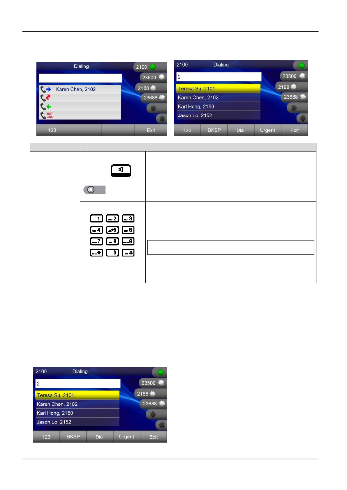
MOCET IP3072 Smart Office IP Desk Phone User Guide
To place a new call:
Operation Description
1. Pick-up the handset or press a line key or press
or
Line Key
the speaker key.
You will hear a dial tone.
Making a call
2. Use the keypad to enter the phone number.
The LCD window displays the digits that you
entered and the matching numbers in Contacts.
Note: You may use the BKSP soft key to delete the last
digit.
3. On-hook the handset when your conversation is
over.
3.6 Placing an Urgent Call
The IP3072 supports Broadsoft’s Urgent Call feature. Please refer to Section 4.4,
Changing Phone Settings for more information on configuration of this feature.
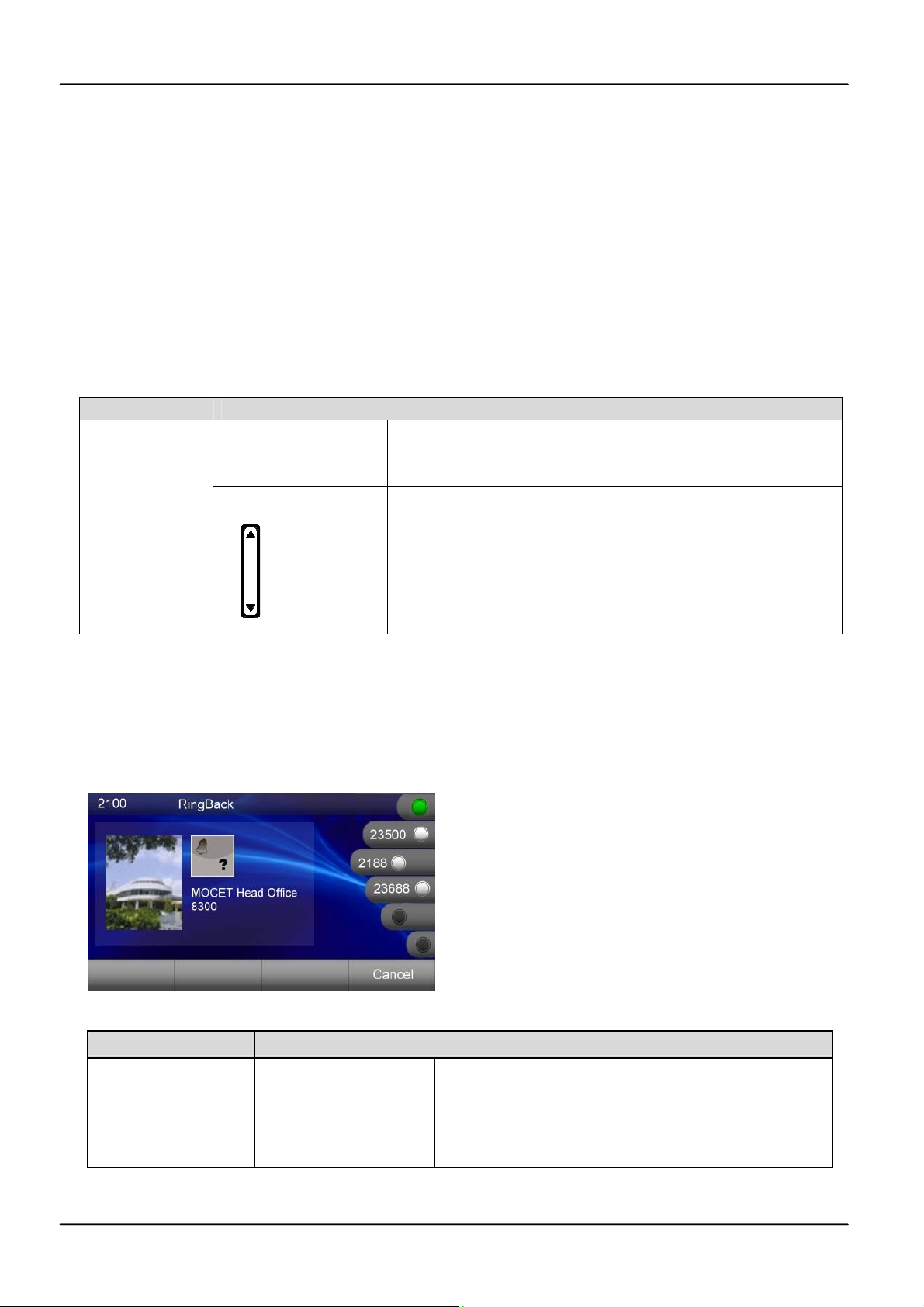
If your IP phone is enabled for “Urgent Call”, when you dial a number, there is an “Urgent”
softkey displayed on the LCD screen.
Page 48
Page 49
MOCET IP3072 Smart Office IP Desk Phone User Guide
If you press the “Urgent” soft key to dial the number out, the call will be marked as an
urgent call. The called party can neither deny nor block the call even the called party’s
phone is on DND.
3.7 Adjusting Call Volume
During a conversation, if the voice volume is too low or too high, you may adjust it.
To adjust volume while on a call:
Operation Description
1. During a conversation, if the voice volume is too
low or too high, you may adjust it.
2. Press the Volume control key Up or Down to
adjust the volume of Speaker, Handset, or Headset.
To adjust
volume
while on a
call
3.8 Canceling a Call
After you dial a call, but the called party has not answered, you can cancel the call by
press “Cancel” soft key.
Operation Description
Press “Cancel” soft-key to reject the call.
Canceling a call
“Cancel”
If only the calling call on the phone, you can just
press speakerphone or put down handset to
cancel the call.
Page 49Page 49
Page 50
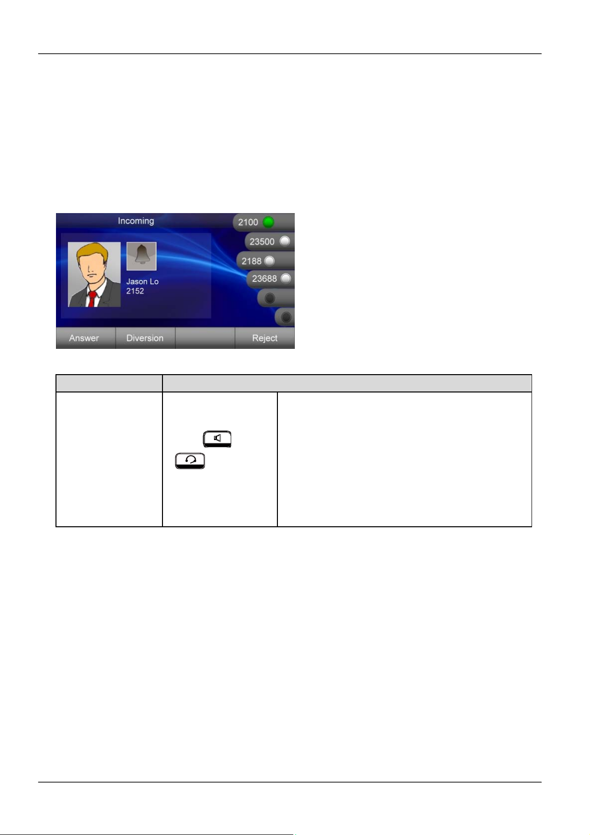
MOCET IP3072 Smart Office IP Desk Phone User Guide
3.9 Answering a Call
When a new incoming call on the phone, you can answer the call by:
Using the handset
Using the speakerphone
Using a headset
Pressing “Answer”soft-key
Operation Description
or or
Answering a call
or Answer
If there is no other call, just pick-up the
handset or press the speakerphone key or the
headset key or press the “Answer” soft-key
upon hearing the phone ringing.
If there is another call, press “Answer” softkey to accept the call, the previous call will be
placed on hold automatically.
3.10 Answering an Urgent Call
When there is an incoming urgent call on the phone, you can answer a call as you would
normally; however, some features will be ignored automatically including DND and call
blocking.
3.11 Rejecting a Call
When there is an incoming call on the phone, you can reject the call.
Page 50
Page 51
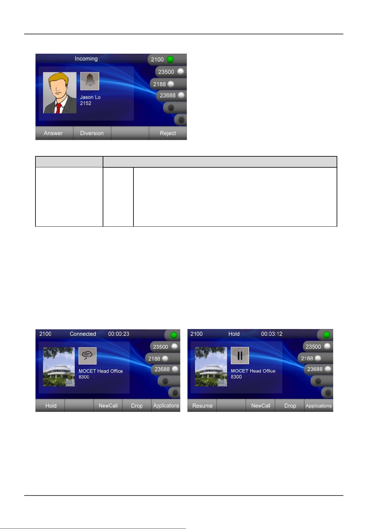
MOCET IP3072 Smart Office IP Desk Phone User Guide
Operation Description
Press “Reject” soft-key to reject the call.
Rejecting a call
Reject
After pressing the “Reject” soft-key, the call will be dropped
directly. The record will be logged in answered call list.
Other call features are not affected by this operation.
3.12 Ending/Holding/Resuming a Call
When a call is in connected state, you can end a call by:
Using the handset
Using the speakerphone
Using a headset
Pressing “Drop” soft-key
Page 51Page 51
Page 52
MOCET IP3072 Smart Office IP Desk Phone User Guide
Operation Description
Ending a call
Holding a call
Resuming a call
or or
or End
or Hold
or Resume
If there is only one call, just place the handset
back into the cradle, press the speakerphone
key or the headset key or press “End” soft-key
to end the call.
If there is another call, press the “End” softkey to end the call.
Press the “Hold” soft-key or Hold key on the
phone to place an active call on hold.
Press the “Resume” soft-key or Hold key on
the phone again to place an active call on
hold.
3.13 Muting and Un-Muting a Call
While in a conversation, you may mute the microphone by pressing the MUTE ()
button. The LED of the button will become blue. When muted, the other caller will not hear
anything from your phone.
Pressing the MUTE ( ) key again will Un-Mute the phone.
3.14 Redialing a Number
To redial the last numbers you dialed:
1. Press Redial( ) hot key.
2. Phone will enter “Dialed Call Log” table.
3. Select the number you want to redial.
4. Press “Dial” soft key to dial out.
For more information, please see 2.2.8. Managing Call Logs.
3.15 Setting up a Conference Call
The IP3072 can support a 3-party conference call.
Page 52
Page 53
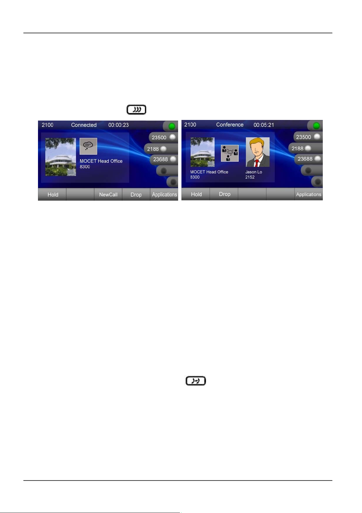
MOCET IP3072 Smart Office IP Desk Phone User Guide
To set up a conference:
1. Call the first party and Hold the call
2. Press “NewCall” soft key to call another party
3. Press the Conference ( ) hot key to set up a 3-party conference
3.16 Transferring a Call
A call can be transferred in one of three ways:
Blind Transfer: The call is automatically transferred after you dial the number of the party
to whom you want to transfer the call.
Semi-Attended transfer: The party to whom you want to transfer the call does not answer
their phone before you transfer the call (when you hear ring-back tone).
Attended transfer: The party to whom you want to transfer the call answers their phone
before you transfer the call. You can consult with them before completing the transfer.
3.16.1 Blind Transfer
To complete a blind transfer:
1. During an active call, press the Transfer ( ) hot key.
2. The active call is placed on hold, and an entry screen is displayed for the number you
want to transfer to.
3. Press Navigation OK or “Dial” soft-key to complete the transfer.
4. If you want to cancel transfer operation, just press the “Exit” soft-key.
3.16.2 Semi-Attended Transfer
Page 53Page 53
Page 54
MOCET IP3072 Smart Office IP Desk Phone User Guide
To do Semi-Attended transfer:
1. During an active call, press “NewCall” soft-key to call another party.
2. When you hear the ring-back tone, press the Transfer ( ) hot key.
3.16.3 Attended Transfer
To do Attendant transfer:
1. During an active call, press “NewCall” soft-key to call another party.
2. Wait for the other party to answer the call.
3. Press the Transfer ( ) hot key.
Note: sometimes, you may place more than 2 calls on your phone, when you press
Transfer ( ) hot key, phone will show a call list to let you select a call to finish the
transfer operation.
3.17 Forwarding a Call
You can configure your phone to forward your incoming call to another party, which is
sometimes called as static forwarding. You can also dynamically forward calls while your
phone is ringing.
There are three types of static forwarding:
Unconditional
No answer
Busy
For more information on how to setup static call forwarding, please contact your
administrator or Service Provider support center.
To use dynamic forwarding:
1. When the phone rings with an incoming call, press the “Diversion” soft-key.
2. Enter a number to forward the incoming call to.
3. Press “Dial” soft-key to forward the call.
3.18 Using Voice Mail
Page 54
Page 55

MOCET IP3072 Smart Office IP Desk Phone User Guide
Your voicemail is saved on either your hosted SIP service or on the IP PBX, but you can
access it from the IP3072 using the Message ( ) hot key.
The presence of new voice mail messages is indicated by a flashing message waiting
indicator (MWI) LED on the front of the phone and an icon is shown on LCD.
Note:
Voicemail is an optional feature configured on a hosted SIP service or IP PBX and
may not be supported on your particular system. To use voicemail on the IP3072, some
settings need to be configured first. For more information please contact your administrator
or Service Provider support center.
To listen your voice messages:
1. Press the Message ( ) hot key to display the mailbox list.
2. Select which SIP line’s mailbox you want to listen to and press “OK”
3. A call will be placed to your voice mail server.
4. Follow the interactive voice response (IVR) instructions to retrieve and listen, forward
or delete your messages.
3.19 Placing a Speed Dial Call
To configure a speed dial number, please see Section 2.2.5 Speed Dialing Setting.
To make a speed dial call:
1. Pickup the handset, or press a line key, or press the speaker key or press the headset
key.
2. When you hear dial tone, long press the one digit (0-9, *, #) speed dial key you
previously configured, the number assigned to the speed dial key will be dialed out.
Page 55Page 55
Page 56
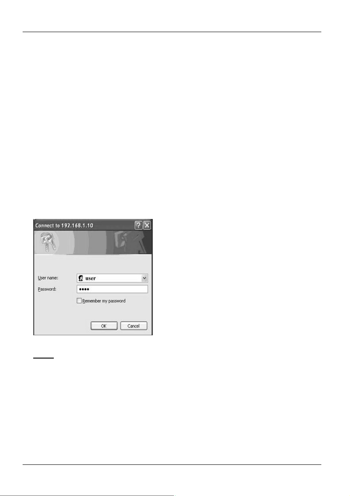
MOCET IP3072 Smart Office IP Desk Phone User Guide
4. Using Advanced Features
The Getting Started chapter describes the steps used to customize the IP3072 from the
LCD menu of the phone. However, there are many advanced features that need to be
set up using the phone’s web user interface. This chapter provides instructions on how
use these features.
4.1 Login Web UI
To use your web browser to configure the IP3072, you need to know the IP address of the
phone on your local area network (LAN). Using the LCD menu, find the IP address of the
phone under Menu > Information > IP Address.
1. Point your web browser to the IP address of the IP3072.
2. Enter the correct Username and Password information into the dialog box and press
OK.
Note: The default Username is “user” and the default Password is “1111” and the default
network settings are:
Default IP address: 192.168.1.10
Default Subnet mask: 255.255.255.0
Default Gateway: 192.168.1.1
Default DNS: 8.8.8.8
Page 56
Page 57
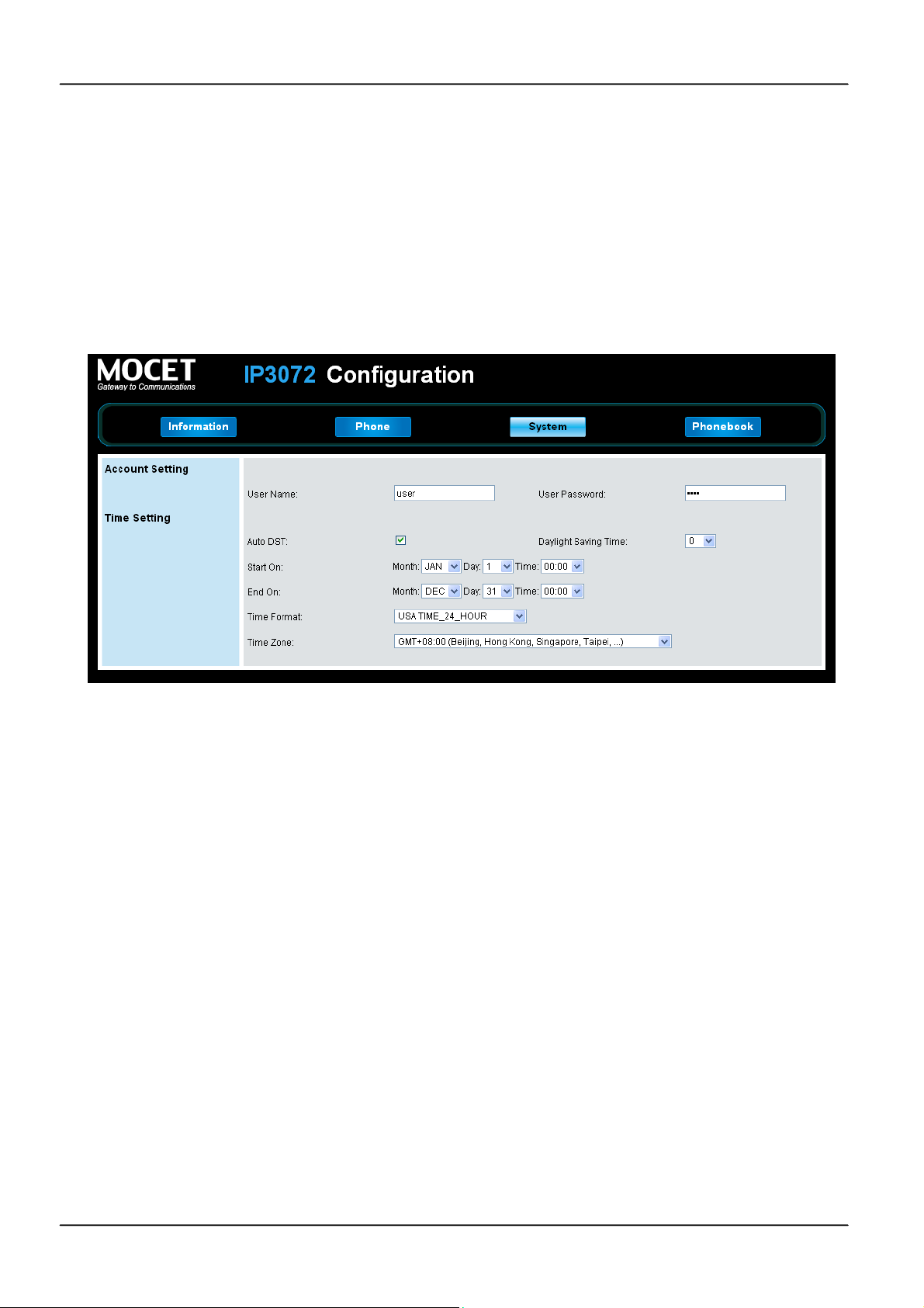
MOCET IP3072 Smart Office IP Desk Phone User Guide
4.2 Changing the User’s Password
Some features of the IP3072 require you to enter a personal identification number (PIN)
for security. The default PIN of the IP3072 User account is “1111”.
To change the User password:
1. Navigate to the System tab
2. Locate “Account Setting” > “User Password:”
3. Change the password to use a new PIN.
4.3 Viewing Phone Information on Web User Interface
Information is the first page you will see when you login to the phone’s web user interface.
This page lets you check the status of the IP Phone including network and product related
information as well as account status information.
Page 57Page 57
Page 58
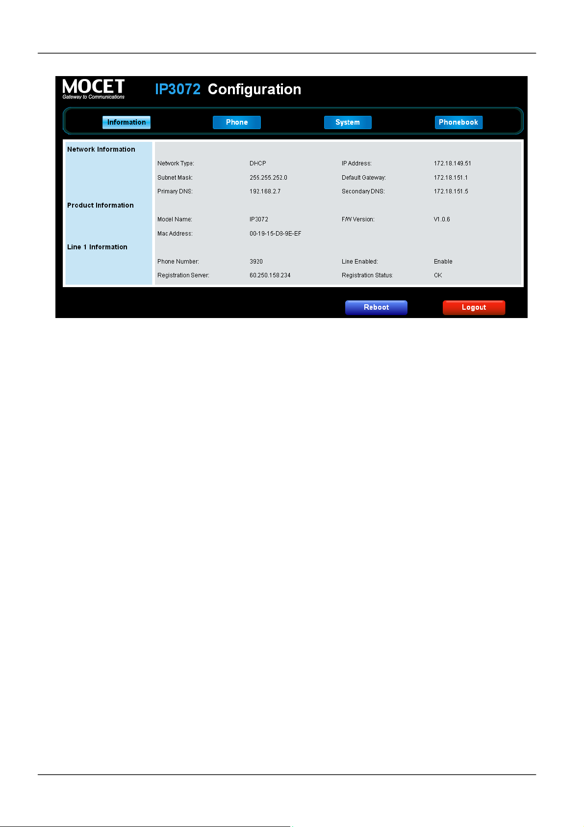
MOCET IP3072 Smart Office IP Desk Phone User Guide
For SIP Line status:
When this line is disabled, the line status will not be displayed.
“Registration State” will be marked “OK”.
“Unregistered” will be marked with red text.
4.4 Changing Phone Settings
Phone Settings enables you to configure private settings for phone. Select the Phone tab
of the web user interface to begin configuration.
From this page you can change following settings:
Device Volume
Tone and Ring types
Voice parameters
Advanced phone features (DND, Auto-answer, Call Waiting, etc)
Speed dial settings
Programmable key settings
Page 58
Page 59
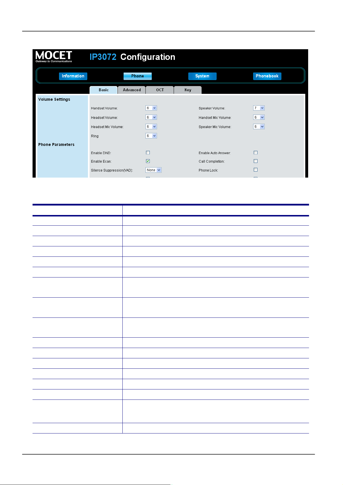
MOCET IP3072 Smart Office IP Desk Phone User Guide
Here is the description of each field.
Field Name Function
Handset Mic
Handset Speaker
Handfree Mic
Handfree Speaker
Ring Tone Volume
Side Tone Volume
Tone Type
Ring Type
Preferred Line
Enable Music on Hold
Enable Auto Answer
Enable DND
Enable Call Waiting
Set the input level of handset microphone.
Set the output level of handset speaker.
Set the input level of hand-free microphone.
Set the output level of hand-free speaker.
Set the output level of ring.
Set the output level of side tone.
Select the tone type.
There are 11 types of standard Tone for selection.
Select the ring type.
There are 11 types of standard Ring for selection.
Select the SIP line automatically to dial out if not press SIP
line manually when dialing.
Plays hold music on phone when held by remote.
Turn on auto answer function.
Turn on DND function, block any incoming all
Turn on call waiting function.
Enable Call Waiting Tone
Enable Hold Reminder
Hold Reminder Time (sec)
Hotline Number
Play call waiting tone when there’s another incoming call.
Turn on the Hold Reminder function.
Set the time (10~60 sec) that phone will remind user with a
tone when the call hold remote every this time period.
Set the hotline number
Page 59Page 59
Page 60
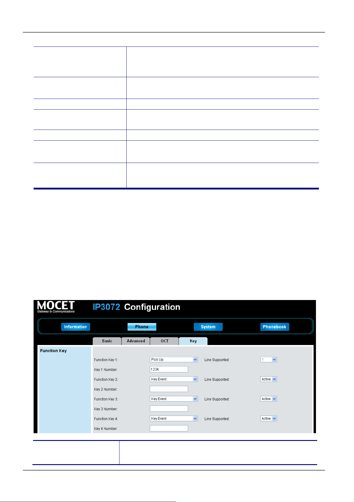
MOCET IP3072 Smart Office IP Desk Phone User Guide
Hotline Timeout(sec)
Set the time (1~60 sec) when phone offhook but not dial,
phone will dial out the hotline number automatically after this
time period.
Dial Timeout (sec)
Enable Phone Lock
Phone Number Display
style
RTP Port Base
Speed Dialing Entry 0~9,*,#
Programmable Key Setting
1~8
Set the time (1~30 sec) that phone will dial out automatically
after this time period.
Lock the phone.
Set the display style for calling name and number.
Set phone local RTP Base Port.
There are 12 speed dial entries for user to store. Each entry
map to the numeric keypad on the IP Phone.
Please refer to section 4.5 Managing programmable Keys.
4.5 Using Programmable Keys
Your IP3072 Phone has 8 programmable keys which can be configured for different
features.
To use the programmable keys, just press the key, then the configured feature will be
executed, some features will blink the LEDs or turn on the related features.
To configure programmable keys, go to Phone tab of the web user interface, and find the
“Key” section:
Function Key 1 ~ 8
Set a specified function for each function key (1-8). There are
many advanced call features that you can select from the list.
Page 60
Page 61

MOCET IP3072 Smart Office IP Desk Phone User Guide
Line Supported 1 ~ 6
Key 1, 2, 3, 4, 5, 6
Number
Select a line number (1-6) which the function key assigned to.
Set a number for the function key.
Programmable Key Function:
Option Name Function
None
Key Event
Set the function key as None. When pressing the function
key, it will have no any action
Set the function key as Key Event. When pressing the
function key, it will perform the function as your setting. You
can set one of the following key events in the "Key" field of
Button Settings page.
F_HOLD
F_CONFERENCE
F_TRANSFER
F_REDIAL
F_HANDSFREE
F_MUTE
F_CONTACTS
F_MESSAGE
F_HEADSET
Speed Dial
Call Blocking
Auto Answer
Set the function key as Speed Dial. When pressing the
function key, it will dial out the phone number as your setting.
Set the function key to Call Blocking. When pressing the
function key, the call blocking setting is enabled, and the
LED of the function key becomes blue. When the blocking
number calls you, your IP Phone will reject the call
automatically, and show a missed call icon on the standby
screen.
Set the function key to Auto Answer. When pressing the
function key, the Auto Answer setting is enabled and the
LED of the function key becomes blue as well as the Auto
Answer icon displays on the top line bar. No matter any
number calls you, your Web IP Phone will pick up calls
automatically.
Page 61Page 61
Page 62

MOCET IP3072 Smart Office IP Desk Phone User Guide
g
r
r
r
DND
Anonymous Call Blocking
Phone Lock
Set the function key to DND (Don’t Disturb). When pressing
the function key, the DND setting is enabled and the LED of
the function key becomes blue as well as the DND icon
displays on the top line bar. No matter any number calls you,
your Web IP Phone will not have any incoming call
displayed, and only show a missed call icon on the standby
screen.
Set the function key to Anonymous Call Blocking. When
pressing the function key, the Anonymous Call Blockin
setting is enabled and the LED of the function key becomes
blue. When any anonymous call calls you, your IP Phone will
reject the call automatically, and show a missed call icon on
the standby screen.
Set the function key to Phone Lock. When pressing the
function key, the Phone Lock setting is enabled and the
LED of the function key becomes blue. You will need to
enter a password to unlock your Web IP Phone. The default
password to unlock phone is 1234.
Transfer
Call Forward Always
Call Forward Busy
Call Forward No-Answer
Set the function key as Transfer. When you have an
incoming call, if you press the function key, the incoming call
will be transferred to the phone number as your setting.
Set the function key to Call Forward Always. When
pressing the function key, the Call Forward Always setting
is enabled, and the LED of the function key becomes blue.
Your IP Phone will forward any incoming calls to the numbe
as your setting.
Set the function key to Call Forward Busy. When pressing
the function key, the Call Forward Busy setting is enabled,
and the LED of the function key becomes blue. Your IP
Phone will forward any incoming calls to the number as you
setting when your IP Phone is off hook or during a call.
Set the function key to Call Forward No-Answer. When
pressing the function key, the Call Forward No-Answe
setting is enabled, and the LED of the function key becomes
blue. Your IP Phone will forward any incoming calls to the
number as your setting when the call does not be picked up
in time.
Page 62
Page 63

Voice Record
r
Busy Line Field
MOCET IP3072 Smart Office IP Desk Phone User Guide
Set the function key to Voice Record. When the "Record"
key is pressed once during a call, the phone sends a SIP
INFO message with * Record: on. Another key press stops
the recording, makes the phone send a SIP INFO message
with * Record: off.
Please be aware that the phone is only triggering the start
and end of the recording on a remote location which has to
perform the recording itself. The phone does not record the
voice streams at all.
Set the function key to Busy Line Field. When the set
number is busy, the LED of the function key is on. If the LED
of the function key is off, you can press the function key to
dial out the set number directly. When the set number is
ringing, the LED of the function key is blinking, and if you
press this key, you can pick up the ringing call.(for Asterisk
PBX only)
Orbit
Pick Up
Call Pick Up
Call Park
Set the function key as Orbit. When pressing the function
key during a call, it will park the call in the parking lot as you
setting. This feature is useful for call center environments
and all places where there is a great inflow of calls and some
kind of queuing is required to manage them.
It's used for SLA/BLA mode, using this feature can pick up a
ringing call on other phone. Note the SIP server should
support SLA. This function has been tested with FreeSwitch.
Set the function key as Pick Up. When pressing the function
key, it will pick up the call in the parking lot as your setting.
Note: To use this function, your server, such as Asterisk,
must support this function.
Call Park Is similar to Orbit, using t his feature will transfer a
call to a park queue on server, a park queue number should
be configured.
Note: To use this function, your server must support this
function.
DTMF
Set the function key to DTMF. When pressing the function
key during a call, the digits set in DTMF setting will be sent
out. To use this function, please set DTMF type as
RFC2833. It’s configurable only in Administration mode.
Page 63Page 63
Page 64
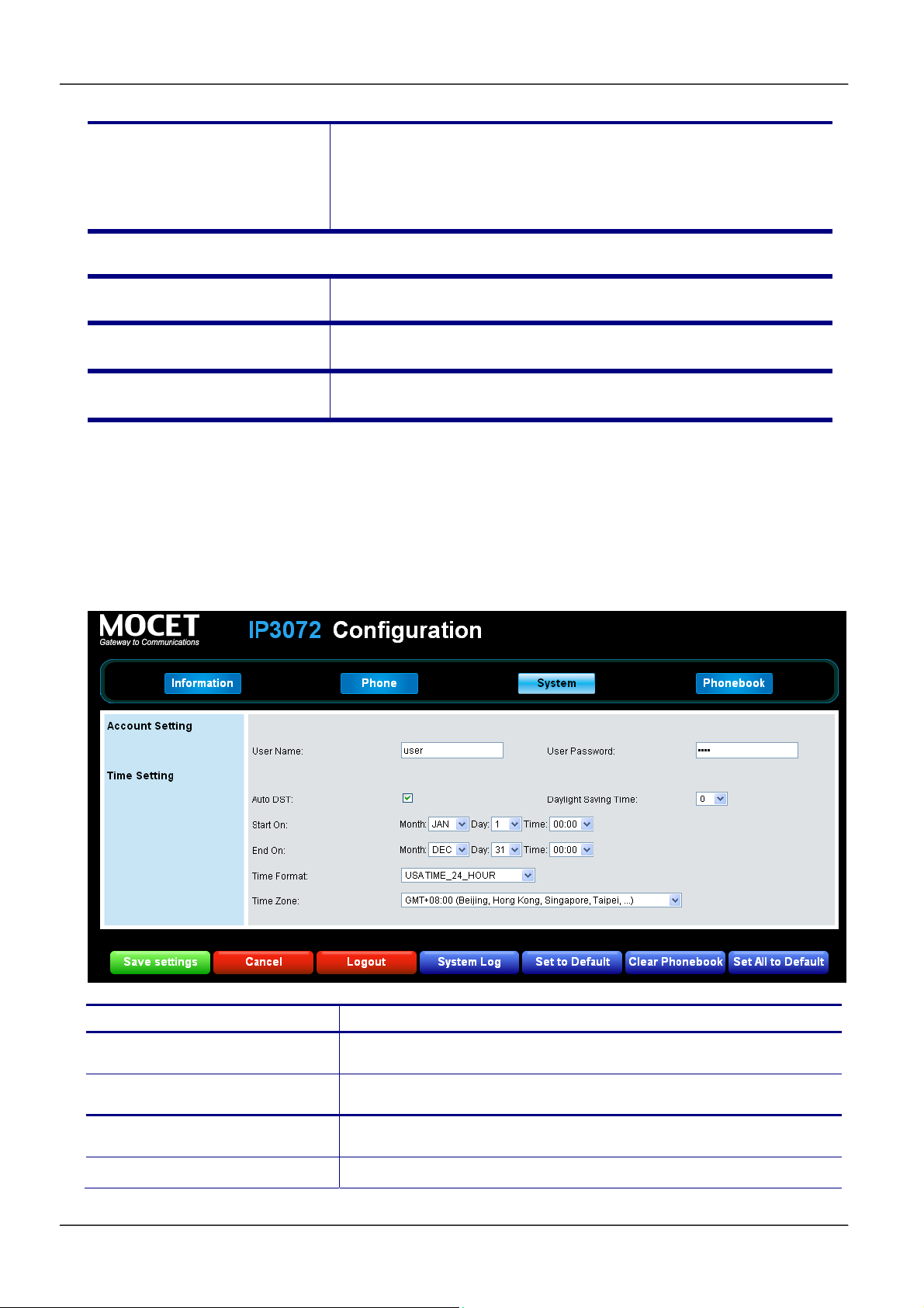
Intercom
r
MOCET IP3072 Smart Office IP Desk Phone User Guide
Set the function key as Intercom. When pressing the
function key, it will dial out the phone number directly as you
setting. This feature is useful in an office environment as a
quick access key to connect to the operator or the secretary.
Save Settings
Cancel
Logout
Save changes in this page to the phone.
Discard all changes in this page.
Logout and close the browser window
4.6 Changing System Settings
On the System tab, the user can access or change:
Account Setting
Time settings
Field Name Function
User Name
User Password
Auto DST
Daylight Saving Time
Set the name for user mode (default: user)
Set the password for user mode(default: 1111)
Enable auto DST (daylight saving time).
Set a value for Daylight Saving Time. There are three
Page 64
Page 65

MOCET IP3072 Smart Office IP Desk Phone User Guide
options, -1, 0 and 1.
Start on
End on
Time Format
Time Zone
Save Settings
Cancel
Logout
System Log
Set to Default
Clear Phonebook
Set start time for DST.
Set end time for DST.
Select a time format showed on the phone LCD display.
Set a time zone for the phone.
Save changes in this page to the phone.
Discard all changes in this page.
Log out and close the browser window.
Press the button to pop up the system log web page.
Press the button to set all parameters of the phone to default.
The phone will auto reboot to make new parameters take
effect.
Press the button to clear up the private phonebook data of the
phone.
Press the button to set all parameters of the phone to default
All Default
as well as clear all phonebook data. The phone will auto
reboot to make new parameters take effect.
4.7 Managing EDM
The EDM setting page appeared only when the EDM is plugged into the phone. The user
can configure the 24 programmable keys of each EDM. For the detailed setting options,
please refer to the section 4.5 Managing Programmable Keys.
Page 65Page 65
Page 66
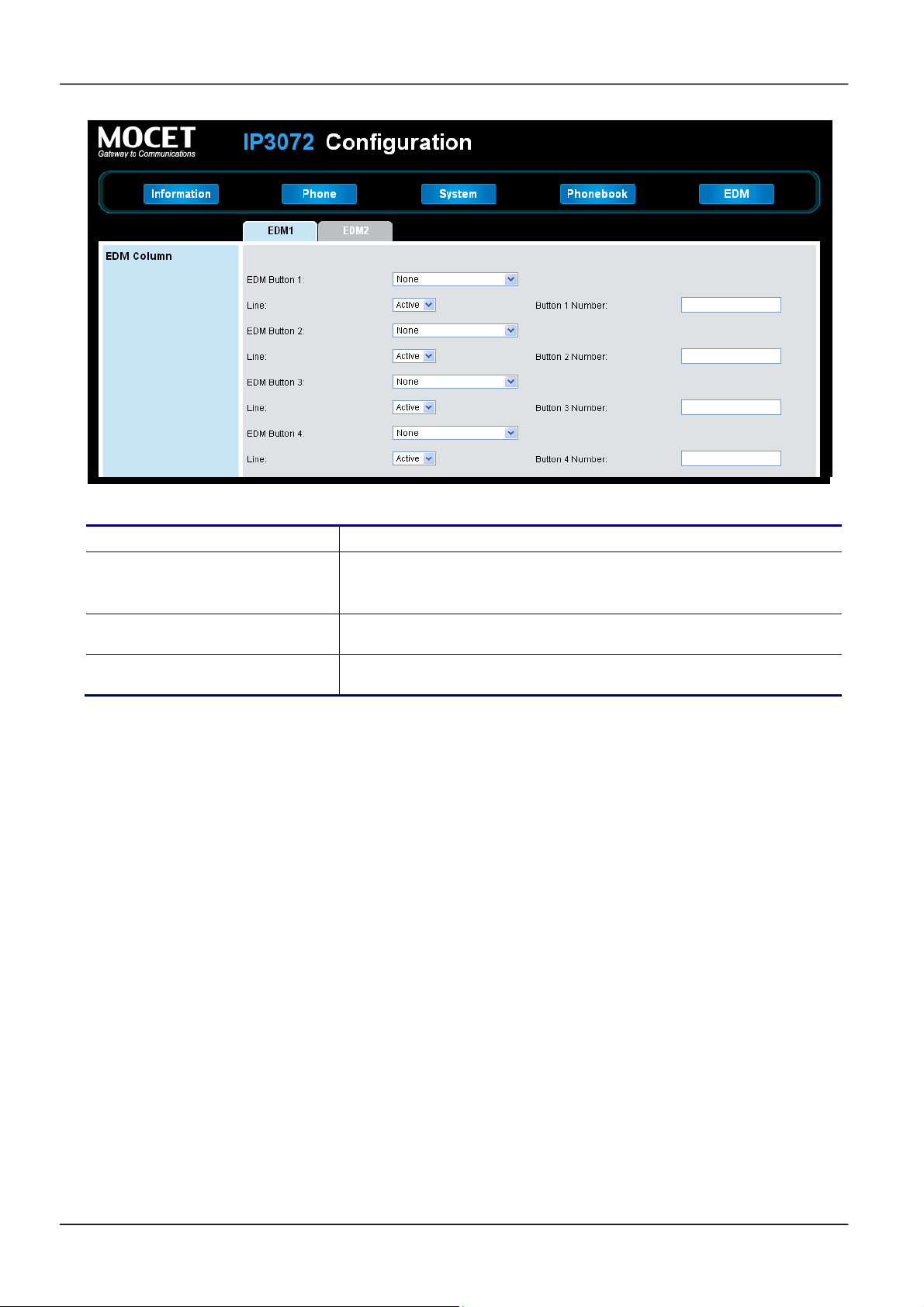
MOCET IP3072 Smart Office IP Desk Phone User Guide
Field Name Function
EDM Button 1, 2,…,24
Line 1, 2, … , 6
Button 1, 2, … , 11 Number
Set a function for the EDM key. (Refer to the Programmable
Key function in the table of section 4.5)
Select a line for the EDM key.
Set a number for the EDM key.
4.8 Managing Phonebook
On the Phonebook tab, the user can manage his phone directories.
4.8.1 Private Phonebook
For the Private Phonebook, the user can add, edit, delete or dial an entry directly from the
web page. The user can also upload his contacts from a file using a web browser. The
Private Phonebook can have up to 100 contacts.
Page 66
Page 67
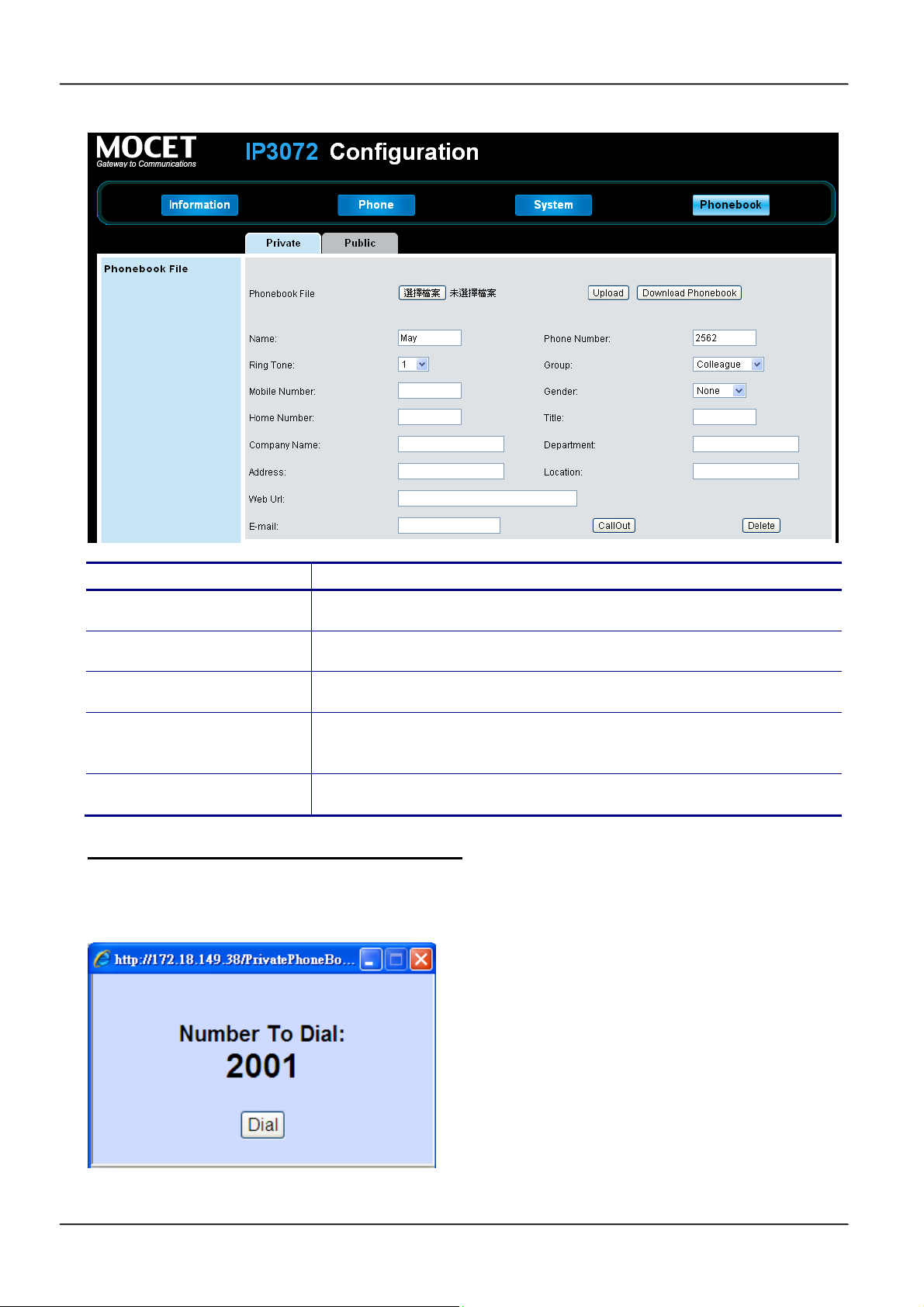
MOCET IP3072 Smart Office IP Desk Phone User Guide
Field Name Function
Upload Phonebook File
Download Phonebook
Group
CallOut
Delete
Placing a Call from the Private Phonebook
When you click the CallOut button to place a call to a private contact, a new Window will
be displayed:
Upload “PhoneBook.xml” to the private phonebook.
Download the current phonebook data from the phone.
Set a group for a phonebook item
Call the phonebook number via web page. It is similar to click-
to-dial feature.
Delete the phonebook number via web page.
The windows will be closed after the number is dialed out.
Page 67Page 67
Page 68
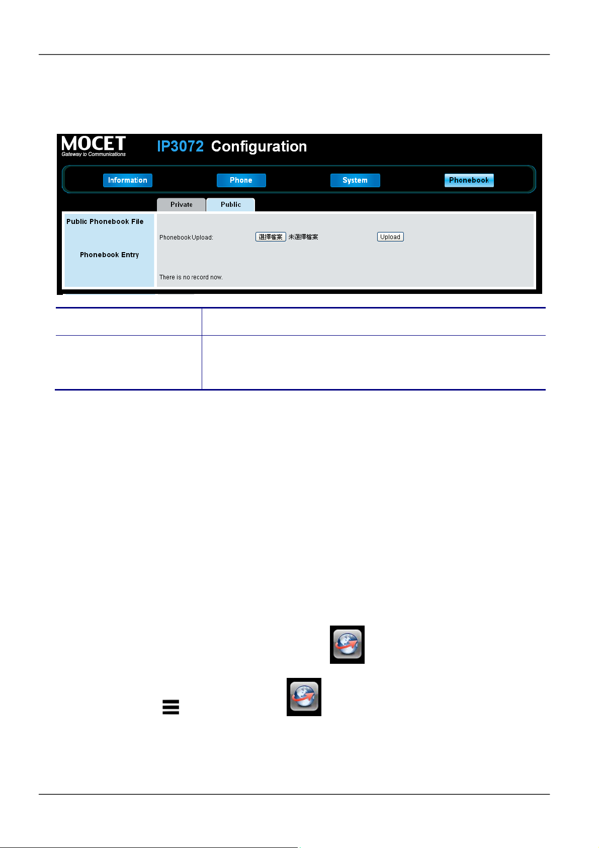
MOCET IP3072 Smart Office IP Desk Phone User Guide
4.8.2 Public Phonebook
For the Public Phonebook, a user or administrator can upload a file using a web browser.
Field Name Function
Upload phonebook data from the computer to the public
Upload Phonebook File
phonebook of the phone. Please note that public phonebook
data is read only, user can’t edit the data.
4.9 XML Web Services
The XML Web Services will be offered thru the XML Server that may support different
applications for users. For example, you can view on-line directory, weather, news,
currency and stocks information in XML Web Services. Moreover, you can order meal
and control remote devices in this menu. However, all contents in the XML Web Services
depend on the offerings of your company XML Web server or your service provider that
they can support. For XML Web Services application requirements, please contact with
your Administrator or Service provider for details.
There are two ways to access the XML Web Server:
1. Press Applications soft-key XML Browser . or,
2. Press “Menu” XML Browser .
Page 68
Page 69

MOCET IP3072 Smart Office IP Desk Phone User Guide
5. Using Advanced Call Features
5.1 Call Waiting
The call waiting feature notifies the user on an active call of a new incoming call. You can
disable the call waiting feature, so that the new incoming call is automatically rejected by
the phone with a busy message.
If you disable call waiting on the phone, and the user is on a call, any further incoming
calls receive busy unless “Call Forward Busy” is configured on the phone, where it then
forwards the call according to the configured destination.
5.2 Intercom Call
5.2.1 Answering an Intercom Call
By default, the IP phone allows incoming intercom calls to be automatically answered on
your phone. If the intercom call comes into the phone while an active call is already
present, the phone puts the active call on hold and answers the intercom call.
5.2.2 Placing an Intercom Call
The Intercom call feature depends on PBX/SIP Server as there are different intercom call
codes for each servers; for example, the Asterisk default intercom code is “*80”.
To place intercom call on an Asterisk server, you may just make a call to “*80”+
[destination number] (“*801001” for example). For other phone systems or hosted SIP
services, please contact your administrator or Service Provider for more information.
Page 69Page 69
Page 70

MOCET IP3072 Smart Office IP Desk Phone User Guide
6.. Using USB Accessories with Your Phone
6.1 USB Keyboard
When attaching a USB keyboard on your phone, there will be a USB keyboard icon on the
LCD screen.
When USB keyboard is connected, you can:
Dial phone number
Edit Phonebook
Edit Speed Dial
Edit Instant Message
Edit Programmable Keys fields and EDM fields
Page 70
Page 71

MOCET IP3072 Smart Office IP Desk Phone User Guide
r
7. Troubleshooting
Symptom Check & Remedy
No operation
No dial tone
LAN connection lost
status message
Cannot make call
Cannot receive a call
Cannot connect to the
IP3072 configuration
pages with a browser
Check if the power adapter is properly connected.
Check if the Ethernet cable is properly connected
Check if the handset cord is properly connected.
Check if the power adapter is properly connected.
Check if the Ethernet cable is properly connected.
Check the status of your SIP registration status or contact
your administrator, supplier or ITSP for more information
or assistance.
Check if the Ethernet cable is properly connected.
Check the status of your SIP registration status, o
contact your administrator, Distributor (dealer) or ITSP for
more information or assistance.
Check if the Ethernet cable is properly connected.
Check the IP address of the IP Phone.
Check if your firewall/NAT settings is correct.
Page 71Page 71
Page 72

8. Glossary
8.1 Acronyms
ANC
APS
B2BUA
CA
CID
CODEC
CNG
CPC
CPE
CWCID
CWI
CWT
DHCP
DNS
DTMF
ETSI
FQDN
FSK
HTML
HTTP
ICMP
IETF
IP
ISP
ITSP
IVR
LAN
LBR
LBRC
MWI
PoE
PPPoE
PSTN
NAT
NTP
RTP
RTCP
SDP
SIP
TFTP
TCP
UDP
URL
VLAN
WAN
XDSL
XML
Anonymous Call
Auto-Provisioning Server
Back to Back User Agent
Certificate Authority
Caller ID
Coder and Decoder of Voice
Comfort Noise Generation
Calling Party Control
Customer Premises Equipment
Call Waiting Caller ID
Call Waiting Indication
Call Waiting Tone
Dynamic Host Configuration Protocol
Domain Name Server
Dual Tone Multiple Frequency
European Telecommunication Standard
Fully Qualified Domain Name
Frequency Shift Keying
Hypertext Markup Language
Hypertext Transfer Protocol
Internet Control Message Protocol
Internet Engineering Task Force
Internet Protocol
Internet Service Provider
IP Telephony Service Provider
Interactive Voice Response
Local Area Network
Low Bit Rate
Low Bit Rate Codec
Message Waiting Indication
Power over Ethernet (IEEE802.3af standard)
Point-to-point protocol over Ethernet (mainly for xDSL modem connection)
Public Switched Telephone Network
Network Address Translation
Network Time Protocol
Real Time Protocol
Real Time Control Protocol
Session Description Protocol
Session Initiation Protocol
Trivial File Transfer Protocol
Transmission Control Protocol
User Datagram Protocol
Uniform Resource Locator
Virtual Local Area Network
Wide Area Network
Digital Subscriber Loop, such as ADSL, VDSL, HDSL, etc.,….
Extensible Markup Language
MOCET IP3072 Smart Office IP Desk Phone User Guide
Page 72
Page 73
MOCET IP3072 Smart Office IP Desk Phone User Guide
8.2 Terminology
10/100BASE-T
It is a LAN transmission line specification stipulated by IEEE.
Transmission speed is 10 or 100 Mbps and the modulation
technique is base-band modulation. The cable uses unshielded
twisted pair, similar to a telephone wire. 10BaseT is an IEEE
standard (802.3) for operating 10 Mbps Ethernet networks (LANs)
with twisted pair cabling and a wiring hub.
802.1p An IEEE standard for providing QoS using three bits (defined in
802.1q) to allow switches to reorder packets based on priority
level.
802.1q An IEEE standard for providing virtual LAN (VLAN) identification
and QoS levels. Three bits are used to allow eight priority levels,
and 12 bits are used to identify up to 4,096 VLANs.
AGC Automatic Gain Control is a feature of IP solutions units that
allows the units to automatically adjust the incoming voice signal
to a user defined level in dBm.
A-law The PCM coding and compression standard used in Europe and
in areas outside of North America influence. A Law Encoding is
the method of encoding sampled audio waveforms used in
2.048Mbps, 30 channel PCM primary system known as E-carrier.
Auto answer In telephone call control: The capability of a machine to answer a
ringing telephone without human intervention.
Autodial In telephone call control: An auxiliary device for a telephone that
automatically dials any of a group of prerecorded telephone
numbers.
Blocked Calls Caused by an insufficient network facility that does not have
enough lines to allow calls to reach a given destination. May also
pertain to a call from an originating number that is blocked by the
receiving telephone number.
Call Completion The point at which a dialed number is answered.
Call Termination The point at which a call is disconnected.
CDR In telephone call control: Call Detail Record for billing
IP Centrex
This service is offered by the LEC to the end user. The feature-
rich Centrex line offers the same features and benefits as a PBX
to a customer without the capital investment or maintenance
charges. The LEC charges a monthly fee to the customer, who
must agree to sign a term agreement. And the abive service is
thru VoIP called IP centrex.
CO Switching center for the local exchange carrier.
Page 73Page 73
Page 74
MOCET IP3072 Smart Office IP Desk Phone User Guide
j
CODEC The CODEC (CODER/DECODER) is a standard through which
voice information can be encoded into data or decoded back to
voice information. Both a Coder and Decoder are necessary on
both sides of the telephone call since telephone calls occur
simultaneously in both directions. Bandwidth is an extremely
important factor in QOS (Quality of Service). MOS (Mean Opinion
Score) is an attempt to make a quantifiable benchmark of voice
quality. Below are examples of the CODEC, bit rate and mean
opinion score: G.711 (toll quality) 64K MOS=4.1, G.726 16K (32K)
MOS =3.8, G.729AB (cell phone quality) 8K MOS=3.7.
Customer
Premise
Equipment
The only part of the telecommunications system that the customer
comes into direct contact with. Example of such pieces of
equipment are: telephones, key systems, PBXs, voicemail
systems and call accounting systems as well as wiring telephone
acks. The standard for this equipment is set by the FCC, and the
equipment is supplied by an interconnect company.
DHCP A utility that enables a server to dynamically assign IP addresses
from a predefined list and limit their time of use so that they can
be reassigned. Without DHCP, an IT Manager would have to
manually enter in all the IP addresses of all the computers on the
network. When DHCP is used, whenever a computer logs onto the
network, it automatically gets an IP address assigned to it.
DID Direct Inward Dialing: The ability to make a telephone call directly
into an internal extension without having to go through the
operator.
Diff-Serv Differentiated Services : The Diff-Serv model div ides traffic into a
small number of classes to provide quality of service (QoS). One
of QoS in internet
Direct inward
dialing
A Centrex feature that allows an outside caller to dial a central
business number, as well as an extension number.
Diversity antenna A type of antenna system that uses two antennas to maximize
reception and transmission quality and reduce interference.
DNS Domain Name Service : A server/program that translates URLs to
IP addresses by accessing a database maintained on a collection
of Internet servers. The program works behind the scenes to
facilitate surfing the Web with alpha versus numeric addresses. A
DNS server converts a name like mywebsite.com to a series of
numbers like 107.22.55.26. Every website has its own specific IP
address on the Internet. Typically one or more DNS servers is
located in an IP network.
DSL Various technology protocols for high-speed data, voice and vide o
transmission over ordinary twisted-pair copper POTS (Plain Old
Telephone Service) telephone wires.
Page 74
Page 75
MOCET IP3072 Smart Office IP Desk Phone User Guide
DSP Digital Signal Processors (DSP) standardize the different states of
a digital signal into an organized and understandable signal. DSP
circuits can differentiate between digital signals and digital noise.
Signal-to-Noise ratio is one of the most important factors in
telephony voice communication because if there is too much noise
in a signal, the DSP will be unable to find a signal standard and
lose it. DSP circuits always adjust digital signal levels so the can
maintain a standard without noise.
DTMF Dual Tone Multi-Frequency: The type of audio signals generated
when you press the buttons on a touch-tone telephone. Can be
used in inbound(after voice channel connected) and
outbound(before voice channel connected) application.
Ethernet International standard networking technology for wired
implementations. Basic 10BaseT networks offer a bandwidth of
about 10 Mbps. Fast Ethernet (100 Mbps) and Gigabit Ethernet
(1000 Mbps) are becoming popular.
G.711 64 kbps PCM half-duplex codec (high quality, high bandwidth,
minimum processor load)
G.723.1 6.4/5.3 kbps MP-MLQ codec (low quality, low bandwidth, high
processor load due to the compression)
G.726 40/32/24/16 ADPCM codec (good quality, medium bandwidth, low
processor load)
G.729 8 kbps ACELP codec (medium quality, low bandwidth, high
processor load)
IEEE Institute of Electrical and Electronics Engineers, New York,
www.ieee.org. A membership organization that includes
engineers, scientists and students in electronics and allied fields.
It has more than 300,000 members. The IEEE is an international
organization that develops standards for hundreds of electronic
and electrical technologies for computers and communications.
The organization uses a series of numbers, like the Dewey
Decimal system in libraries, to differentiate between the various
technology families.
IP (Internet
Protocol)
Internet Protocol is located at 3rd layer of ISO network model. A
set of rules used to send and receive messages at the Internet
address level. IP protocol is widely used in Internet and LAN
networks. The purpose is to deliver data between computing
equipment over the network. The protocol is generally effective
but does not guarantee complete and accurate data
communications.
IP address A 32-bit number that identifies each sender or receiver of
information that is sent across the Internet. An IP address has two
parts: an identifier of a particular network on the Internet and an
identifier of the particular device (which can be a server or a
workstation) within that network. A number used to identify the
location of a host device. It is expressed in numeric dot notation
(e.g. 202.203.27.31).
Page 75Page 75
Page 76

MOCET IP3072 Smart Office IP Desk Phone User Guide
IP Centrex This service is offered by the LEC to the end user. The feature-
rich Centrex line offers the same features and benefits as a PBX
to a customer without the capital investment or maintenance
charges. The LEC charges a monthly fee to the customer, who
must agree to sign a term agreement. And the abive service is
thru VoIP called IP centrex.
Jitter Jitter refers to fluctuations in transmission delay time. In the case
of voice data, conversations are packaged into packets (IP
packetization) and transmitted. Individual packets can take
different routes through the varied networks that comprise the
Internet. When the time interval for the arrival of the packets is not
constant the timing fluctuations that may occur are referred to as
"jitter".
MAC Medium Access Controller (MAC) : The IEEE 802.11 Standard
encompasses the physical layer (PHY) and the lower portion of
the data link layer. The lower portion of the data link layer is often
referred to as the Medium Access Controller (MAC) sublayer.
Every wireless 802.11 device has its own specific MAC address
hard-coded into it. This unique identifier can be used to provide
security for wireless networks. When a network uses a MAC table,
only the 802.11 radios that have had their MAC addresses added
to that network's MAC table will be able to get onto the network.
NAT Network Address Translation : A network capability that enables a
houseful of computers to dynamically share a single incoming IP
address from a dial-up, cable or xDSL connection. NAT takes the
single incoming IP address and creates new IP address for each
client computer on the network.
Numbering plan In a communications network, a numbering plan allocates specific
numeric codes to identify each subscriber line, special lines, trunk
lines, etc. Numbering plans can be divided into the numbering
system and number assignments. The numbering system
indicates the number of digits to be assigned and the basic
scheme of number assignment. The assignment of specific codes
is performed according to the numbering system.
PBX Private Branch eXchange :An in-house telephone switching
system that interconnects telephone extensions to each other as
well as to the outside telephone network.
Peer-to-peer
network
A wireless or wired computer network that has no server or central
hub or router. All the networked PCs are equally able to act as a
network server or client, and each client computer can talk to all
the other wireless computers without having to go through an
access point or hub. However, since there is no central base
station to monitor traffic or provide Internet access, the various
signals can collide with each other, reducing overall performance.
POTS Plain Old Telephone Service (POTS), or Pretty Old Telephone
System is the standard analog traditional telephone service that
most homes use. In contrast, telephone services based on high-
speed, digital communications, such as ISDN and DSL, are not
POTS. The main distinctions between POTS and non-POTS
services are speed and bandwidth.
Page 76
Page 77
MOCET IP3072 Smart Office IP Desk Phone User Guide
Proxy server Used in larger companies and organizations to improve network
operations and security, a proxy server is able to prevent direct
communication between two or more networks. The proxy server
forwards allowable data requests to remote servers and/or
responds to data requests directly from stored remote server data.
PSTN Public Switched Telephone Network: The worldwide voice
telephone network.
QoS Quality of service (QoS)
RJ-45 Standard connectors used in Ethernet networks. Even though they
look very similar to standard RJ-11 telephone connectors, RJ-45
connectors can have up to eight wires, whereas telephone
connectors have only four.
Router A device that forwards data packets from one local area network
(LAN) or wide area network (WAN) to another. Based on routing
tables and routing protocols, routers can read the network address
in each transmitted frame and make a decision on how to send it
via the most efficient route based on traffic load, line costs, speed,
bad connections, etc.
RTP/RTCP Real-Time Protocol/Real-Time Control Protocol(RTP / RTCP) :
IETF specifications for audio and video signal management.
Allows applications to synchronize and spool audio and video
information. RTP (Real Time Protocol) is specifically concerned
with the dependable transmission of latency-sensitive traffic
across the network and is involved in using time stamping to
determine network jitter tolerance and makes sure that voice
packets are arriving in order.
SIP Session Initiation Protocol :A protocol that provides telephony
services similar to H.323, but is less complex and uses less
resources. SIP (Session Initiation Protocol) is a signaling protocol
for Internet conferencing, telephony, presence, events notification
and instant messaging. SIP is a text-based protocol, similar to
HTTP and SMTP, for initiating interactive communication sessions
between users.
Subnetwork or
Subnet
Found in larger networks, these smaller networks are used to
simplify addressing between numerous computers. Subnets
connect to the central network through a router, hub or gateway.
Each individual wireless LAN will probably use the same subnet
for all the local computers it talks to.
TCP/IP Internet Standard Protocol: The underlying technology behind the
Internet and communications between computers in a network.
The first part, TCP, is the transport part, which matches the size of
the messages on either end and guarantees that the correct
message has been received. The IP part is the user's computer
address on a network. Every computer in a TCP/IP network has
its own IP address that is either dynamically assigned at startup or
permanently assigned. All TCP/IP messages contain the address
of the destination network as well as the address of the
destination station. This enables TCP/IP messages to be
transmitted to multiple networks (subnets) within an organization
or worldwide.
Page 77Page 77
Page 78

MOCET IP3072 Smart Office IP Desk Phone User Guide
TOS Type of Service: A method of setting precedence for a particular
type of traffic for QoS.
UDP User Datagram Protocol. An unreliable networking layer that sits
at the same level of the networking stack at TCP. UDP is a
connectionless transport protocol that is part of a suite of protocols
(the others being RTP and IP) that allow for the timely and
efficient transfer of voice data across and IP network. UDP is the
better transport protocol for VoIP data than TCP.
VAD Voice Activity Detection (VAD) helps save bandwidth during calls.
Examples: When your making a VoIP call and your not speaking
and your listening, that silence is still taking up bandwidth during
the call. When silence is detected by VAD software over a
predetermined length of time, is sends silent packets that inform
other VAD enabled systems to stop holding the bandwidth for
these empty packets.
VoIP Voice Over Internet Protocol: VoIP is based on the principal of
transmitting digitized voice packets over networks. Basically, VoIP
consists of converting voice signals into streams of digital packets
and sending those packets of data through an IP-constructed
network environment. VoIP can work in both LAN (local area
network) and WAN (wide area network) environments for
intranetwork or internetwork communication between VoIP
channel users. Routers and switches and other special
compression protocols direct the packetized voice data to their
destination IP address. VoIP can be less expensive than voice
transmission using standard analog packets over POTS (Plain Old
Telephone Service). It allows telephone calls, faxes, or overhead
paging to be transported over an existing IP data network
topology.
VPN Virtual Private Network(VPN) is a virtual created sub-network
based on a public real network. A type of technology designed to
increase the security of information transferred over the Internet.
VPN can work with either wired or wireless networks, as well as
with dial-up connections over POTS. VPN creates a private
encrypted tunnel from the end user's computer, through the local
wireless network, through the Internet, all the way to the corporate
servers and database.
AN Wide Area Network: For global or long distance networking
access thru the support of telecommunication devices. A
communication system of connecting PCs and other computing
devices across a large local, regional, national or international
geographic area. Also used to distinguish between phone-based
data networks and Wi-Fi. Phone networks are considered WANs
and Wi-Fi networks are considered Wireless Local Area Networks
(WLANs).
WLAN Also referred to as LAN. A type of local-area network that uses
high-frequency radio waves rather than wires to communicate
between nodes.
============= The End of Document ===============
Page 78
 Loading...