

Page 1
MOCET
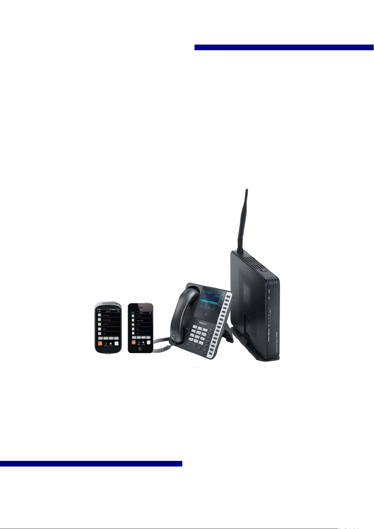
Smart Telephone System
IG7600
Administration Manual
Page 2

IG7600 Administration Manual
Environment
The equipment you have purchased must not be disposed of with household waste. You
should return these to your distributor if they are to replace or dispose of them in an
approved recycling centre.
FCC Statement
This equipment generates, uses, and can radiate radio frequency energy and, if not
installed and used in accordance with the instructions in this manual, may cause
interference to radi o communi cations . This eq uipment has been tested and fou nd to compl y
with the limits for a Class B computing devic e pursuant t o Subp art J o f Part 15 o f FCC rules ,
which are designed to provide reasonable protection against radio interference when
operated in a commercial environment. Operation of this equipment in a residential area is
likely to cause interference, in which case the user, at his own expense, will be required to
take whatever measures are necessary to correct the interference.
Copyright Notice
All rights reserved. No part of this publication may be reproduced, transmitted, transcribed,
stored in retrieval system or translated in to any language or computer language, in any
form or by any means, electronic, mechanical, magnetic, optical, chemical, manual, or
otherwise, without the prior written permission of Company.
Company reserves the rig ht to revi se the publicat ion and mak e chang es from tim e to time i n
the contents hereof without obligation of this company to notify person of such revision or
changes. The material contained herein is supplied without representation or warranty of
any kind. The Company therefore assumes no responsibility and shall have no liability of
any kind arising from the supply or use of this document or the material contained herein.
Trademarks
Windows 98/NT/2000/XP/7™ and Internet Explorer™ are registered trademarks of
Microsoft Corporation. All other company, brand and product names, like Netscape
Navigator™ are trademarks or registered trademarks of their respective owners.
I
Page 3

IG7600 Administration Manual
WARNING!
1. Read these installation instructions carefully before connecting the equipment to its
power adapter.
2. To reduce the risk of electric shock, do not remove the cover from the equipment or
attempt to dismantle it. Opening or removing covers may expose you to dangerous
voltage level s. Eq ually , incor rect r eass embly coul d caus e el ectri c sh ock on re-us e o f the
appliance.
3. Do not expose the equipment to fire, direct sunlight or excessive heat.
4. Do not ex pose th e equi pme nt to r ain or moistu re and do n ot allow i t to c ome into c ont act
with water.
5. Do not install the equipment in an environment likely to present a Threat of Impact.
6. You may clean the equipment using a fine damp cloth. Never use solvents (such as
trichloroethylene or aceton e), whic h may dam age the equipment’s plastic sur face. Nev er
spray the equipment with any cleaning product whatsoever.
7. The equipment is designed to work in temperatures from 0oC to 45oC (32oF to 104oF).
8. The equi p me nt m us t b e installed at least 1 meter from radi o fr eq uency equipment, such
as TVs, radios, hi-fi or vi deo equipment (which radiate electromagnetic fields).
9. Do not connect the LAN/WAN port to any network other than an Ethernet network.
10. D o not atte mpt to upgr ade your eq uipment in an unstabl e power env ironment. This coul d
cause unexpected damages .
11. Do not work on the system during lightning storms. Please disconnect all cables.
12. Children don't recognize the risks of electrical appliances. Therefore use or keep the
equipment only under supervision of adults or out of the reach from children.
13. No repair can by performed by the end user, if you experience trouble with this
equipment, for repair or warranty information, please contact your supplier.
Electrical Powering :
The IG7600 can be powered with correct power adaptor; the power adaptor must be
12V/1.5A. Any damage caused to the IG7600 as a result of using unsupported power
adaptors will not be covered by the manufacturer’s warranty.
Product Disposal Warning:
Ultimate disposal of this product, accessories, packing, especially the batteries should be
handled carefully for recycle and nature protection in accordance with national laws and
regulations.
II
Page 4

IG7600 Administration Manual
Table Of Contents
Introduction ...................................................................................................................................................... 1
1.
2. Getting to Know the IG7600 .......................................................................................................................... 3
2.1 Front Panel ................................................................................................................................................... 3
2.2 Rear Panel .................................................................................................................................................... 4
3. IG7600 Voice General Feat ur es ................................................................................................................... 5
3.1 3-Way Conference .......................................................................................................................... 5
3.2 Access Control for Web Page ......................................................................................................... 5
3.3 Answering Position ........................................................................................................................ 5
3.4 Auto Attendant & Voice Mail ......................................................................................................... 5
3.5 Auto Provisioning........................................................................................................................... 7
3.6 Basic Call ....................................................................................................................................... 7
3.7 Call Abandon .................................................................................................................................. 7
3.8 Call By Name ................................................................................................................................. 8
3.9 Call Operator (Call Attendant) ..................................................................................................... 10
3.10 Call Pickup – Group ..................................................................................................................... 10
3.11 Call Restriction ............................................................................................................................. 10
3.12 Call Routing ................................................................................................................................. 12
3.13 Caller ID Detection/Generation .................................................................................................... 12
3.14 Class Of Service (COS) ................................................................................................................ 13
3.15 Daylight Saving Time ................................................................................................................... 13
3.16 Default Set .................................................................................................................................... 13
3.17 Direct In Dialing (DID) ................................................................................................................ 13
3.18 Direct Inward System Access (DISA) .......................................................................................... 14
3.19 Emergency Call ............................................................................................................................ 14
3.20 Extension Password ...................................................................................................................... 14
3.21 Fax/Modem .................................................................................................................................. 14
3.22 Flash – Analog Port (SLT) Flash Recognition .............................................................................. 14
3.23 Hold Recall Time.......................................................................................................................... 14
3.24 IP T runk ........................................................................................................................................ 15
3.25 Message Waiting Indication (MWI) ............................................................................................. 15
3.26 Music on Hold .............................................................................................................................. 15
3.27 Numbering Plan ............................................................................................................................ 15
3.28 PSTN Backup ............................................................................................................................... 16
3.29 Registration Server ....................................................................................................................... 16
3.30 Remote Registration ..................................................................................................................... 16
3.31 Service Mode ................................................................................................................................ 17
3.32 Station Message Detailed Recording (SMDR) ............................................................................. 17
3.33 System Speed Dial........................................................................................................................ 18
3.34 System Time & Date .................................................................................................................... 18
3.35 Trunk Group ................................................................................................................................. 18
3.36 UCD (Uniform Call Distribution) Group (or Hunt Group) .......................................................... 18
3.37 IGW Group ................................................................................................................................... 18
3.38 Wizard Setup ................................................................................................................................ 24
4. IG7600 Voice Extension Feat ur es .............................................................................................................. 25
4.1 3-Way Conference ........................................................................................................................ 26
4.2 Agent Log On/Off – UCD Group ................................................................................................. 26
4.3 Alphanumeric Display .................................................................................................................. 26
4.4 Automatic Callback Busy ............................................................................................................. 26
4.5 Auto Hold ..................................................................................................................................... 27
4.6 Call Fork ....................................................................................................................................... 27
4.7 Call Forward ................................................................................................................................. 27
4.8 Call Hold ...................................................................................................................................... 28
4.9 Call Log ........................................................................................................................................ 28
III
Page 5

IG7600 Administration Manual
4.10 Call Park / Call Park Answer ........................................................................................................ 28
4.11 Call Pickup – Individual ............................................................................................................... 29
4.12 Call Waiting .................................................................................................................................. 29
4.13 Caller Blocking ............................................................................................................................ 29
4.14 CO Flash ....................................................................................................................................... 29
4.15 COS Following ............................................................................................................................. 29
4.16 Distinctive Ringing....................................................................................................................... 29
4.17 Do Not Disturb (DND) ................................................................................................................. 30
4.18 DSS/EDM ..................................................................................................................................... 30
4.19 Feature Button Reset .................................................................................................................... 30
4.20 Feature Key Programming ........................................................................................................... 30
4.21 Feature Reset ................................................................................................................................ 30
4.22 Hold Reminder ............................................................................................................................. 31
4.23 Hotline .......................................................................................................................................... 31
4.24 Live Recording (One Touch Record) ........................................................................................... 31
4.25 Multi-Line Appearance ................................................................................................................. 31
4.26 Mute ............................................................................................................................................. 32
4.27 On Hook Dialing .......................................................................................................................... 32
4.28 Paging (All/Group) / Paging Answer ........................................................................................... 32
4.29 Paging Allow/Deny ...................................................................................................................... 32
4.30 Phone Book .................................................................................................................................. 32
4.31 Phone Lock/Unlock ...................................................................................................................... 32
4.32 Plug & Play .................................................................................................................................. 33
4.33 Reminder Tone ............................................................................................................................. 33
4.34 Service Mode Switching .............................................................................................................. 33
4.35 Transfer / Recall ........................................................................................................................... 33
4.36 Volume Control ............................................................................................................................ 33
4.37 Web Management ......................................................................................................................... 34
5. Quick Installation ........................................................................................................................................... 35
5.1 Connecting the IG7600 .............................................................................................................................. 35
5.2 Wizard Setup .............................................................................................................................................. 35
5.2.1 WAN Setting ................................................................................................................................... 35
5.2.2 Secondary WAN Setting ................................................................................................................. 37
5.2.3 LAN Setting .................................................................................................................................... 37
5.2.4 Wireless Basic ................................................................................................................................. 38
5.2.5 Internet Time ................................................................................................................................... 38
5.2.6 Wizard Setup Finished .................................................................................................................... 39
6. Configuration ................................................................................................................................................. 40
6.1 Setup .......................................................................................................................................................... 40
6.2 Establish the Connection ........................................................................................................................... 40
6.3 Device Info ................................................................................................................................................ 42
6.3.1 Summary ......................................................................................................................................... 42
6.3.2 Statistics .......................................................................................................................................... 42
6.3.3 Route ............................................................................................................................................... 43
6.3.4 ARP ................................................................................................................................................. 43
6.3.5 DHCP .............................................................................................................................................. 44
6.4 Advanced Setup ......................................................................................................................................... 45
6.4.1 WAN ............................................................................................................................................... 45
6.4.2 Secondary WAN ............................................................................................................................. 47
6.4.3 LAN ................................................................................................................................................ 47
6.4.4 NAT ................................................................................................................................................ 48
6.4.5 Security ........................................................................................................................................... 51
6.4.6 Parental Control .............................................................................................................................. 53
6.4.7 Quality of Service ........................................................................................................................... 55
6.4.8 Routing ........................................................................................................................................... 56
6.4.9 Dynamic DNS ................................................................................................................................. 57
6.4.10 Upnp ............................................................................................................................................. 59
6.5 Wireles s ..................................................................................................................................................... 59
IV
Page 6

IG7600 Administration Manual
6.5.1 Basic ............................................................................................................................................... 60
6.5.2 Security ........................................................................................................................................... 62
6.5.3 MAC Filter...................................................................................................................................... 64
6.5.4 Wireles s Bridge ............................................................................................................................... 65
6.5.5 Advanced ........................................................................................................................................ 65
6.5.6 Station Info ..................................................................................................................................... 68
6.5.7 Power Saving .................................................................................................................................. 68
6.6 Voice .......................................................................................................................................................... 69
6.6.1 Phone .............................................................................................................................................. 69
6.6.2 Trunk ............................................................................................................................................... 77
6.6.3 System ............................................................................................................................................ 85
6.6.4 Voice Mail ....................................................................................................................................... 95
6.6.5 NAT Traversal ............................................................................................................................... 102
6.6.6 Diagnostics ................................................................................................................................... 105
6.6.7 Registered Phone .......................................................................................................................... 106
6.7 Management ............................................................................................................................................ 108
6.7.1 Settings ......................................................................................................................................... 108
6.7.2 TR-069 Client ............................................................................................................................... 109
6.7.3 Time Setting ...................................................................................................................................110
6.7.4 Access Control ...............................................................................................................................112
6.7.6 IP Camera ......................................................................................................................................115
6.7.7 Upgrade Software ..........................................................................................................................115
6.7.8 Upgrade Phone Software ...............................................................................................................116
6.7.9 Upgrade Door FW .........................................................................................................................116
6.7.10 APNS Certificate .........................................................................................................................117
6.7.11 Reboot ..........................................................................................................................................118
6.8 Diagnostics ...............................................................................................................................................119
6.9 Logout ...................................................................................................................................................... 120
6.10 Web UI Language .................................................................................................................................. 120
Appendix 1: Product Summary ......................................................................................................................... 121
Appendix 2: Feature Acce ss Codes ................................................................................................................. 124
V
Page 7
IG7600 Administration Manual
1. Introduction
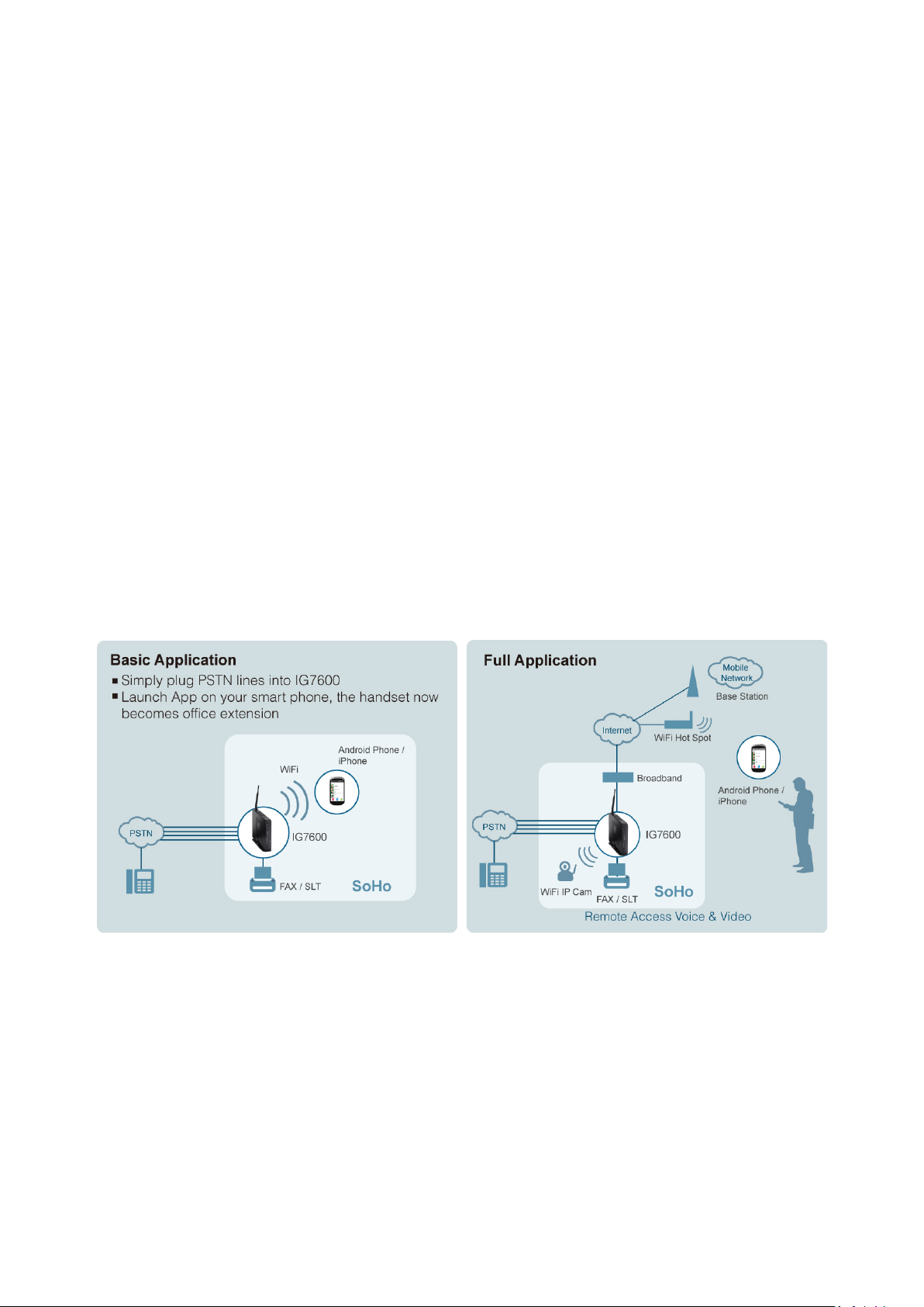
MOCET IG7600 Smart Telephone System is the ultimate SME solution which has rich
feature set of IP PBX telephone systems and IP networking systems. It has business
essential PBX f eatures s uch as a n auto-att endant, v oice mail, multi- line appearances, three
way call confer encing, inter com, music o n hold, call -forwarding and much more. The IG7600
system opens up access to the benefits of VoIP, including low cost long distance service,
and one network for both voice and data.
The IG7600 is so easy to configure that a fully working sy stem can be set up in minu tes. Plug
and Play feature allows IP phone, iPhone or Android phone with M54 App to be
automatically detected and registered when they are connected. The IG7600 is easy to be
managed and configured by integrated web server.
The IG7600 system should work with MOCET IP Phones IP2061/M22/M62 and take
advantages of powerful business features such as plug & play, all paging/group paging,
multi-line appearances, etc….The IG7600 has one FXS port to support traditional analog
devices such as telephone, answering machine, FAX machine.
Copyright 2013 Tecom, Co. LTD. All rights reserved Page 1 of 127
Page 8

IG7600 Administration Manual
1.1 Interfaces
WAN Interface: one 10/100/1000 Base-T Ethernet port
LAN Interface: one 10/ 100 Base-T Ethernent por t
CO Interface: 4 FXO (Loop Start, for PSTN)
Analog Device Interface: 1 FXS (for analog Telephone or FAX)
Built-in 802.11b/g/n WiFi access point
Auto-Pairing button
1.2 Terminals
1 Analog Terminal (Analog Telephone or FAX)
49 IP Stations (IP-Phone; Max. 16 M54 A pp for iPhone/ Android Phone)
1.3 Accessary
Wi-Fi Repeater
Basically, the Administration is required to do the following things:
(1) To understand the architecture, resources, and devices of whole environment
which will be involved with the VoIP communications.
(2) To build a common setting file for most users.
(3) To configure each phone and install them into the network.
(4) To configure each interfaces and install them into IG7600.
(5) And to solve the problems that users encounter during operation.
Copyright 2013 Tecom, Co. LTD. All rights reserved Page 2 of 127
Page 9
IG7600 Administration Manual
LED Name
Color
Status
Description
Red Flashing
Application Restarting
Red On
Firmware updating
Blue Flashing
System booting up
Blue On
System initialized and running
Off
Power off
On
Wireless LAN is active
Off
Wireless LAN is idle
Off
PSTN Line is idle
On
PSTN Line is active
Off
Phone is idle
On
Phone is active
On
LAN is connected
Off
LAN is not connected
LAN activity present (traffic in either
direction)
Blue On
WAN is connected and IP is obtained
Red On
WAN is not connected or no IP assigned
WAN activity present (traffic in either
direction)
2. Getting to Know the IG7600
2.1 Front Panel
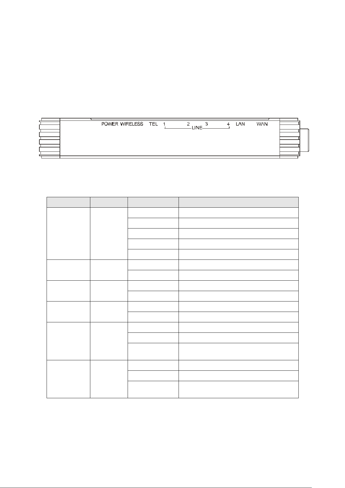
The front panel contains several LEDs that indicate the status of the IG7600.
Figure 2-1. Front Panel of IG7600
POWER Red/Blue
WIRELESS Blue
LINE (1-4) Blue
TEL Blue
LAN Blue
WAN Red/Blue
Flashing
Copyright 2013 Tecom, Co. LTD. All rights reserved Page 3 of 127
Flashing
Page 10
IG7600 Administration Manual
the device to your cable modem, or to your
2.2 Rear Panel
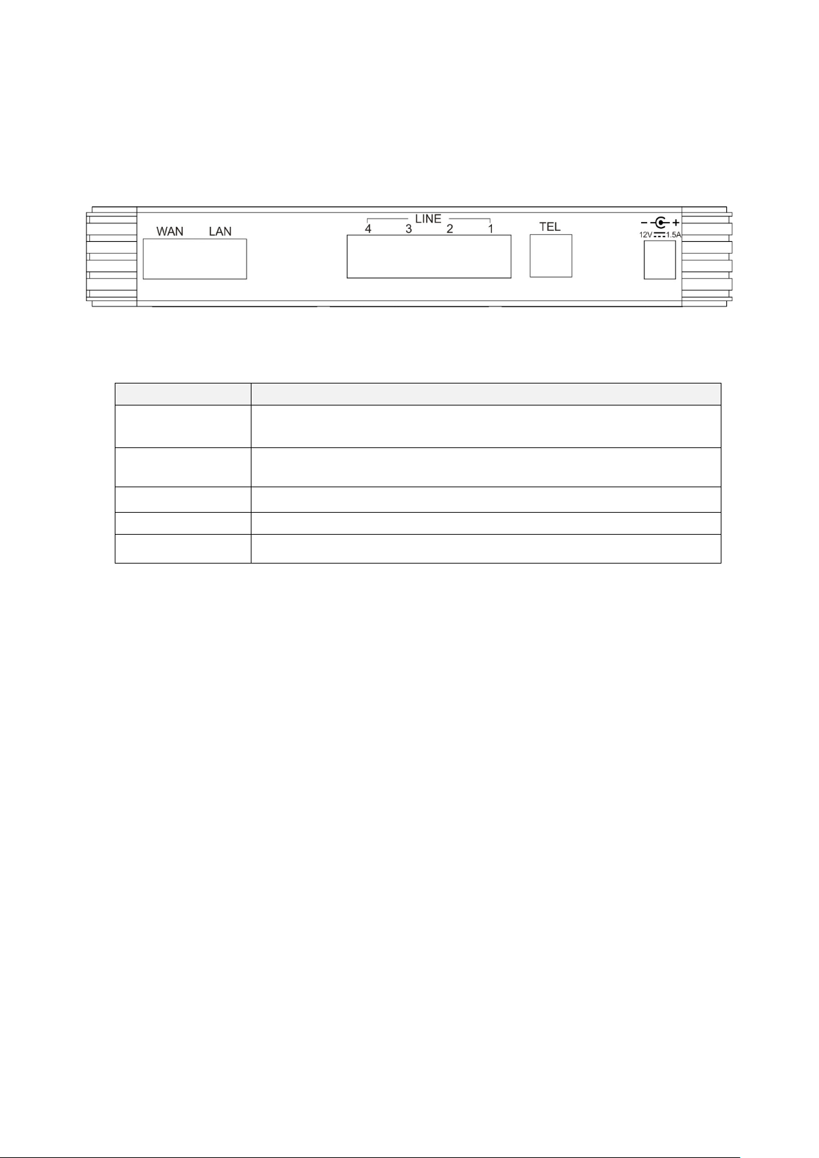
The rear panel contains the ports for the IG7600's data and power connections.
Figure 2-2. Rear Panel of IG7600
Label Function
WAN
LAN
Line (1-4) RJ-11 connector: Connects the device to your PSTN lines.
TEL RJ-11 connector: Connects the device to your analog phone.
Power Connects to the supplied power converter cable.
RJ-45 connector: Connects
ADSL Modem. It’s to connect to the remote network.
RJ-45 connector: Connec ts t he d evic e t o your PC's Ethernet port, or to the
uplink port on your LAN's hub.
Copyright 2013 Tecom, Co. LTD. All rights reserved Page 4 of 127
Page 11

IG7600 Administration Manual
3. IG7600 Voice General Features
3.1 3-Way Conference
IG7600 supports 3-w ay confere nce. C onfer enc e allow s mul tiple s pe akers to participate in
a joint telephone conversation. Each participant in a conference can speak and hear the
other participant s . I G7600 supports one conference room with at m ost 3 par ti ci pa nt s. The
voice is mixed on IG7600.
PS:IG7600 supports this function only when it is a new hardware version IG.
3.2 Access Control for Web Page
The Access Control settings allow the System Administrator to configure the Web Port,
Service Control List, IP Address Access Control mode and password for Administrator,
Supporter and User.
IG7600 also provide an external user access to the internal IP phone’s Web page. The
Registered Phone page will list all registered phones with their IP links for IP phone.
Clicking a specific link will open that specific IP phone’s Web page.
IG7600 provides three Ac ces s modes for Web Page
- Administrator mode: u nr es tr ic ted ac ces s and configuration
(Default: admin1234/adminxxxxxx xxxxxx are the last 6 characters of IG’s MAC
Address.)
- Support Mode: allow an ISP technician to maintain and run diagnosti c s
(Default: support/supportxxxxxx, xxxxxx are the last 6 characters of IG’s MAC
Address)
- User Mode: view some configuration settings and statistics.
(Default: user/user xxxxxx, xxxxxx are the last 6 characters of IG’s MAC Address)
3.3 Answering Position
For incoming calls from the Public Switched Telephone Network (PSTN) (via analog CO
or FXO ports), th e I G7 600 pr ovides the flex ibi l i ty to ring specific destinations. The IG7 600
provides the ability to ring Auto Attendant. The IG7600 also provides the ability to
simultaneously ring up to 50 extensions when programmed in a UCD Hunt Group, or the
Operator in accordance with the system service mode (day or night). The user can also
assign a line to ring directly to an extension. Incoming VoIP calls from a registered ITSP
can be programmed and routed in the same manner as the analog CO (FXO) ports.
3.4 Auto Attendant & Voice Mail
The IG7600 Auto Att endant c an g reatly enha nc e busin ess prod ucti vi ty by prov iding either
a full-time automated att endant to handle all incoming system calls or part-time
automated attendant to handle overflow traffic. The Voice Mail Module provides up to 16
hours recording time that are shared by all extensions. The system can handle four
Copyright 2013 Tecom, Co. LTD. All rights reserved Page 5 of 127
Page 12

IG7600 Administration Manual
simultaneous calls with following functions.
• Auto Attendant Functions
The Auto Attendant pr ov i des an inco ming cal ler w ith a cus tomiz ed w elcome g reeting
and specific prompts that will describe the options available to the caller.
Play the welc ome gr eeting messages depending on the system service mode:
Working, Holiday, and Temporary.
In Working Service mode, play the welcome greeting messages depending
on the system service time: Day, Night, Noon, and Holiday.
Route the call to the appropriate destination (phone/virtual extension, UCD
group, operator, single digit) with the dialing digit(s).
Leave a message to a partic ular mai lbox.
Make an outside call via another trunkline (PSTN or SIP-Trunk).
Enter Voicemail box.
•
AA Menu
Supports ten different Auto Attendent. Each AA’s access number is “S tart AA
& VM Service Number” plus 0, 1, 2, and 3. For example, if “Start AA & VM
Service Number” is 500, then 1st AA is 500, 2nd AA is 501, 3rd AA is 502 and so
and so on.
Only the first AA has default voice prompts (10001~10005.vox), Other Auto
Attendants’ voice prompts (10006~10050.vox) need to be recorded manually.
AA Menu has a speed dial menu which is configured in Voice -> Voice Mail ->
General -> Single Digit Table. This Table can quickly get your call to the
destination that you wanted.
If an AA is set as Destination of a DID entry or Answering Position of a trunk,
the outside caller will hear Dial Tone when it’s answered, then it can call
extensions by dialing extension numbers. It’s used to allow outside devices to
be able to dial extension numbers, UCD Group entry ID, AA entry, any
appropriate destinat ion.
• Voice Mail Functions
Delete, save, or skip messages.
Forward messages to other mailboxes.
- Specified mailbox
- All mailboxes.
Envelop information indicating the time and date of the message received;
sender information will also be included in the email notification.
Leave a new message to other extension(s).
Change personal greeting and password.
Expert mode support (playback controls when reviewing messages).
Send a notification via email when a new message is left.
Send voice message as the attachment of the email in WAV format.
The maximum recording length for each call is 1800 seconds.
When 90% of the VM size is used, it shows “Message Full” on the all
IP2061/M22/M62’s LCD.
For each extension, the maximum number of Voice Mail is 200.
Copyright 2013 Tecom, Co. LTD. All rights reserved Page 6 of 127
Page 13

IG7600 Administration Manual
Each message can be saved for 1 - 30 days or permanently.
Support 50 Virtual Mailboxes
Enter voicemail through another phone extension
• Management Menu
Change the Greeting Mode: Working, Holiday, and Temporary.
Record the Greeting Messages
Record other voice prompts.
• Voice Messages
Provide two languages service for the all voice files.
Support G711-ulaw, G711-alaw, G729 three voice files.
Administrators can record the all voice messages by themselves.
Administrators can update, backup or delete the all voice messages from/to
the PC.
For the detail, please refer Appendix 3.
NOTE: When an extension’s voicemail is filled up to more than 100 mails, VM
system will just read “You have 99 mails.”
3.5 Auto Provisioning
WAN Management Protocol (TR-069) allows an Auto-Configuration Server (ACS) to
perform auto-configur a ti on, pr ovision, collecti on, a nd diagnostics to this dev i c e. F ir mware
upgrade or vendor configuration file backup can be done remotely on ACS server. Select
the desired values and click "Save Settings" to configure the TR-069 client options.
An Auto Provision Server (APS) is also provided to update IG7600 FW , Update / Retriev e
IG7600 Configuration and the registered IP2061/M22/M62 firmware, Management->PTC
page is used to configure IG7600 to communicate with APS Server.
3.6 Basic Call
To make an intercom call, dial a Station number (IP Terminal, POTS) or a Voice Mail
number.
To make an outside call, dial a phone number. IG7600 chooses a line (PSTN line, IP
trunk, another IG7600) via Call Routing Table to dial out.
To make an outside call, dial a PSTN, an IP Trunk or a Trunk Group number first. After
hearing dial tone, dial the phone number.
3.7 Call Abandon
For every PSTN call, IG7600 provides the facility to monitor the call status. If the remote
party hangs up, the ongoing call will be terminated.
The PSTN line monitor is ac complis hed thr ou gh monit oring th e loop-break signal, polarity
reversal or busy t one. Th e v al ue r ang e o f loo p-break signal is: “Di s able” /100/200/…/1000
ms.
Copyright 2013 Tecom, Co. LTD. All rights reserved Page 7 of 127
Page 14

IG7600 Administration Manual
3.8 Call By Name
IG supports Call by Name now, but it is not enabled as default. We should activate it
manually before we use it.
Get ready for dial by name process:
1st find the web page Voice-> Voice Mail->General->Auto Attendant->Dial by Name
Code and We input a number ( for example “9“) here to use it as a dial by name code.
2nd configure extension user name, for example “Sam Hsu” for extension 205, in
Voice->Voice Mail->Phone Extension page as below.
3rd Dial 500(as the default Voice mail service number) or pres si ng “Message” button
on IP phone (#205)
Copyright 2013 Tecom, Co. LTD. All rights reserved Page 8 of 127
Page 15

IG7600 Administration Manual
input your password (default “0000”)
press “5”
Record your name and press “#” key, for exampl e say ing “Sam Hsu” and t hen press “#”
key after the beep tone.
4th Record day g reeting for auto attendant Dial 500(as the default Voice mail ser vic e
number) or pressing “Message” button on IP phone input your password (default
“0000”) press “*” Input administrator password “000000” press “3” press
“10001” press “1” to confirm press “2” to record the greeting, including the greeting
with like “f or dial by name, please dial “9”….” press “1” to listen to the current greeting
to confirm if it is OK.
Now IG7600 is ready for dial by name process.
Incoming call to Auto attendant and transfer the call thru “dial by name”:
Incoming call to IG7600
auto attendant pickup
auto attendant playing “…for dial by name, please dial “9”…”
dial “9” on remote caller
auto attendant playing “Using the letters on the telephone keypad, dial the person's
first or last name and then press pound. For "q" press 7. For "z" press 9.”
dial the number on remote caller, for example, dial “726” for “Sam” or dial “468” for
“Hsu” (The dialed name will be finished when the caller presses “#” or stops the digit
dialing in 5 seconds. )
auto attendant playing “when you hear the correct name, please dial “1”..”(after the
caller inputs the name; AA compares the dialed name with these activated First Name
and Last Name. Then AA starts to play the matc he d ext ensi o n’ s name file. If it matches
two or more extensions’ names, these extensions’ name files will be played one by one
following by the extension number. The interval between two name files is 5 seconds.)
press “1” to confirm the selection on remote caller
the call will be transferred to phone (#205 with Sam Hsu), phone #205 will be ringing
pick up the call on phone #205 and start the conversation.
In Dial by Name process, a voice prompt (10230.vox) will be played to ask the caller to
input the name.
after the caller inputs the name; AA compares the dialed name with these activated First
Name and Last Name. Then AA starts to play the matched extension’s name file. If it
matches two or more extensions’ names, these extensions’ name files will be played one
by one following by the extension number. The interval between two name files is 5
seconds.
When hearing the matched name, the caller dials “1”. AA will transfer the call to the
extension of the m atched n ame ( if it’s a Vi rtua l Ex tensi on, the c all w il l be answ er ed by th e
mailbox of the Virtual Extension directly). If the caller dials a non-“1” digit, the digit will be
ignored.
If it has no matche d na me or the call er does n’t dial “1” after pl ayi ng the all matc hed n ame ,
AA will play a war ning message ( 10232. vox ) , then pl ay a v oi ce pro mpt ( 10234 .v ox) to ask
the caller to select the next oper ation. Pr ess “1”, it will ask the call er to input a na me again .
Press 2, back to AA greeting.
Copyright 2013 Tecom, Co. LTD. All rights reserved Page 9 of 127
Page 16

IG7600 Administration Manual
3.9 Call Operator (Call Attendant)
IG7600 supports one Primary operator and one Secondary operator. Any extension can
be designated as the operator through system configuration.
One primary operator may be assigned in the system. When assigned as operator, this
extension supports general system functions.
While the internal extension dials Operator Directory Number ("0" at default), or the
outside party dials the Operator Directory Number when Auto Attendant plays the
welcome message, these calls will be stored into Operator Queue. The Operator is
First-In-First-Out to service these calls. For the incoming trunk calls at the waiting time,
the calling party will be on Music-On-Hold state.
A secondary (alternate) operator position may be designated for common sharing of
incoming operator cal ls during peak traffic period. If operator doesn’t answer the oper a tor
call in Operator Reroute Time, the call is forwarded to Secondary Operator. If Secondary
Operator doesn’ t ans wer the c al l in Oper ator R eroute Tim e al so, the call w ill be for w arded
to Operator’s mailbox .
3.10 Call Pickup – Group
Each extension belongs to a Pickup Group. Direct Call Pickup allows extension users to
answer a trunk call that is ringing at other extensions. If dialing “*”, allow you to easily
access trunk calls ringing in your group. If dialing All Pickup Group Directory number,
allow you to access any trunk calls ringing in the system. Calls ringing at extensions in
other pickup groups may also be answered using the Directory number assigned to that
Pickup Group.
3.11 Call Restriction
IG7600 provides sophisticated monitoring of digits dialed on PSTN/IP Trunks. If a digit or
range of digits dialed on a Trunk line is inconsistent with the dialing extension’s COS, the
call is denied. This calling COS criteria can be applied to local calls, long distance calls,
and specific numbers that are considered allowed in areas where other numbers may be
restricted.
•
From/To
The intervals ar e mad e up of a From and To e ntr y which establish a num er i c r ang e.
For example, an entry of “From 1700”, “To 1800” would include the following range
of numbers as the leading: 1700, 1701, 1702 …1799, 1800. Each From/To entry
can be from 1 to 13 digits long and may contain any digit 0-9, *, #, X/x (representing
any digit) and +. The “From” entry must be less than or equal to the “To” entry.
•
Trunk Access
IG7600 checks the fiel d only w hen a call mat ches th e ass ociate d entry. If the field is
set to “Y”, the entry is valid when the trunk is accessed previously. If the field is set
to “N”, the trunk isn’t accessed previously. The trunk will be accessed through Call
Routing Table. If the option is set to “YN”, the entry is valid no matter the trunk is
accessed or not previously.
•
COS
The entry in the Allowed Table is matched when the extension’s COS value is
smaller than or eq ual to the COS o f thi s entr y, while the entr y i n t he Denied Table is
matched when the extension’s COS value is larger than or equal to the COS value
Copyright 2013 Tecom, Co. LTD. All rights reserved Page 10 of 127
Page 17
IG7600 Administration Manual
of this entry.
•
Table Type
It decides into which table this entry will be added.
•
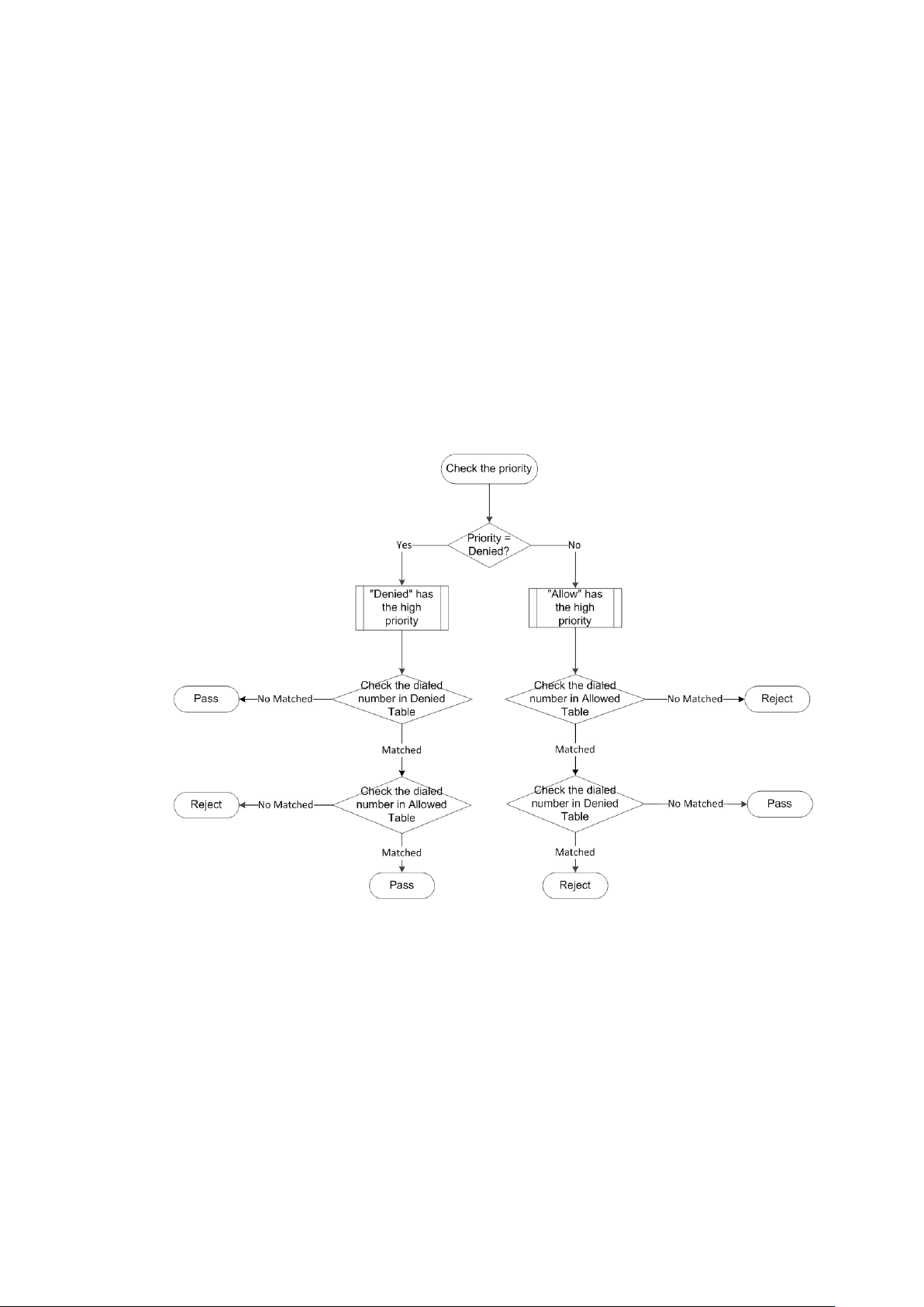
Priority
It decides which table will be checked first.
If Priority is “Allowed”, IG7600 will check Allowed Table first, if any entry is matched
IG7600 will search Denied Table then, the call can be made only when there is any
matched entry found in Allowed Table and there is no any matched entry found in
Denied Table.
If Priority is “Denied”, IG7600 will check Denied Table first, if any entry is matched
IG7600 will search Allowed Table then, the call will be forbidden only when there is
any matched entry found in Denied Table and there is no any matched entry found
in Allowed Table.
Below is a figure that shows the process:
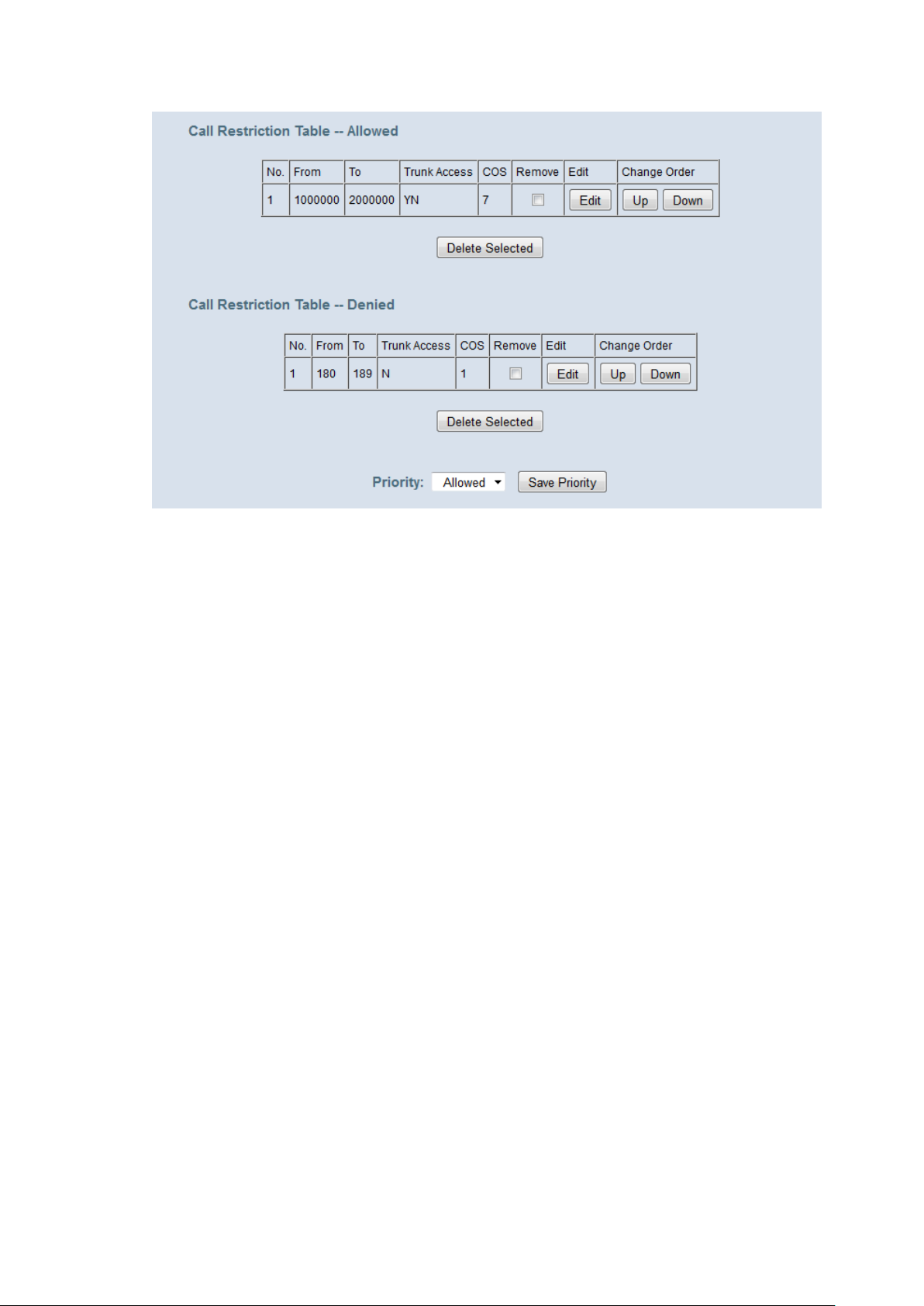
Example:
We can take an example to explain the det ail s.
Consider we have a Call Restriction Table like the picture shows.
Copyright 2013 Tecom, Co. LTD. All rights reserved Page 11 of 127
Page 18
IG7600 Administration Manual
Since the priority is allowed, we should check the allowed table first.
In Allowed table, since 1000000 has 7 digits, you can only dial the number that is
between 1000000 and 2000000 w ith a leng th not less th an 7, and the extension y ou
use must have a COS level higher or equal to “7”.
If you’v e passed the Allow ed Table, chec k the Deni ed Table then, This Denied tabl e
means that when you dial the number directly, and the first three number is
between 180 and 189, your ex tensi on must have a COS lev el hig her or equal to “1”,
if not, your call will be rejected by IG.
3.12 Call Routing
The Call Routing feature automatically routes outgoing calls using the most appropriate
route. The appropriate r oute is det er mi n ed ba s ed on the nu mber dialed. If necessary,
IG7600 can automatically modify the dialed number by deleting and inserting digits.
The call routing destination is a PSTN line, an IP line or a line group. It allows you to
configure each entry in the Call Routing Table which contains a routing rule for outgoing
calls:
- From/To setting defines the number range
- Min/Max defines the match length
- Del can delete some leading digits in the dialed number.
- Insert can add some digits as the leading for the target number. It will be added
after doing “Del”.
- Destination defines the outbound call interface trunk
3.13 Caller ID Detection/Generation
IG7600 provides the ability to detect the calling party identification provided by CO via
PSTN lines or by Uplink Server via IP trunks. This data when received by the telephone
carrier will be displayed on all ringing IP phones.
Copyright 2013 Tecom, Co. LTD. All rights reserved Page 12 of 127
Page 19

IG7600 Administration Manual
IG7600 also provide Caller ID Generation to the Caller ID equipped Single Line
Telephone.
3.14 Class Of Service (COS)
IG7600 provides 8 Classes of Service (COS) for assignment of outside line
dialing-privileges. Each extension may be assigned one Day-COS and one Night-COS.
The Extension COS is primarily used for restriction and control of long distance dialing.
COS 0 is the highest priority. COS 7 is the lowest one.
3.15 Daylight Saving Time
Daylight Saving Time (DST) feature supports auto adjustment for daylight saving time. It
allows you to configure the Daylight Saving Time (DST) which includes support for auto
adjustment of daylight saving time.
- Internet Time: it obeys the international standard rule.
- Manual DST Rule: it allows you to define your own Daylight Savings Time Rule.
3.16 Default Set
Clear all settings and return the IG7600 set to the factory condition will take at most 5
minutes.
When rebooting the IG7600 to the default, some settings for the registered IP Phones
(IP2061, M22 and M62) and Smart Phones are reset to the default also.
- Line Keys
- Call Forward (Direct, Busy, No Answer, DND, Call Fork)
- Phone Lock
- Call Waiting
- Call Waiting Tone
3.17 Direct In Dialing (DID)
IG7600 provides a Di rect In Diali ng Table for IP Trunks. It will be able to offer its indiv idual
phone number for each extension.
IG7600 provides 100 entries in the Direct In Dialing Table. Each entry includes
- DID Number: used to check the Calling Party Number of the incoming call.
- Destination: the ringing destination of the incoming call. It can be a Phone
Extension, Virtual Extension, Auto Attendant, UCD Group, Speed Dial, or Paging
number. It also can be an outside phone number.
- Outgoing Call ID: used as the private Caller ID when the “Destination” user makes
the outgoing call. When the setting is null, it assumes to be the same as “DID
Number”.
- Display Name: used as the Caller Name when the “Destination” user makes the
outgoing call.
- Trunk: the applied trunk(s) of this DID entry. If it’s “All”, this entry will be applied for
the all IP Tru nks.
Copyright 2013 Tecom, Co. LTD. All rights reserved Page 13 of 127
Page 20

IG7600 Administration Manual
3.18 Direct Inward System Access (DISA)
The feature allows you to remotely access IG7600 lines to make the outside calls. The
current PSTN/IP lines are all DISA lines. While ringing to Auto Attendant, the outs ide
callers have direct access to extensions, or make an outside call,
The out-calling is to dial a pound (“#” ) key at the b egi nning when A uto Atte ndant play s t he
greeting message. The call is secured by means of verified passwords against the
assigned extension number. The use is accomplished only when a valid extension
number has been entered and when the password entered matches that stored for the
extension number ente r ed.
The DISA function is disabled by default.
3.19 Emergency Call
IG7600 allows you configure five Emergency Call numbers and lines with which
Emergency Calls are sent out. Any user can make an Emergency Call regardless of its
Call Routing table, Call Restriction, and Phone Lock, when they dial a pre-configured
Emergency Call number. The numbers of Emergency Call must not collide with the
numbers in Numbering Plan.
It allows programming 5 emergency numbers. “911” is in it by default.
3.20 Extension Password
All extensions of the IG7600 system have an associated User Password. The Password
is applied to Voice Mail service, and some system feature settings (Phone Lock, COS
Following, DISA, Forward, Restore to Default, Feature Button Reset).
The Extension Password is 4-digit length. The default is “0000”.
3.21 Fax/Modem
IG7600 supports FAX/ mod e m tone detection and auto-fallback to G.711. IG7600 also
support to use T.38.
3.22 Flash – Analog Port (SLT) Flash Recognition
Flash is the momentary operation of the hook-switch at the analog device, which can be
deciphered by the IG 7 600 system in such a way that the previous c all i n pr og r ess i s hel d ,
or placed in a status of transfer awaiting further instructions from the user.
3.23 Hold Recall Time
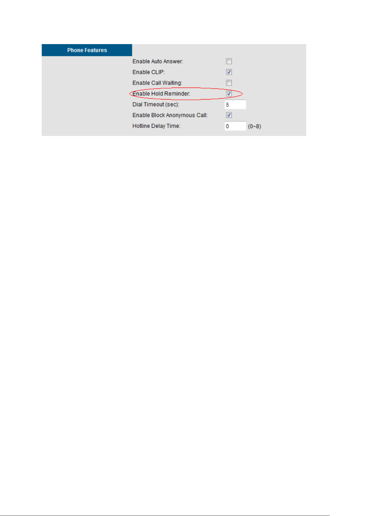
If a call is been hold for a long time, longer than the “hold recall time”, IG will ring the IP
Phone that holds the call.
PS:
1 How to set Hold Recall Time? Please refer to section 6.6.3.3 Transmission.
2 This function works only when the IP Phone enables hold reminder on its
webpage as below.
Copyright 2013 Tecom, Co. LTD. All rights reserved Page 14 of 127
Page 21
IG7600 Administration Manual
3.24 IP Trunk
IG7600 can register up to 12 SIP Uplink Servers. The extensions may make a call to the
users of the Uplink Servers, or any user in the world through the Uplink Servers.
• SIP messages, including INVITE, re-INVITE, ACK, CANCEL, BYE, REGISTER,
INFO, REFER and NOTIFY messages
• SIP Proxy, SIP Outbound Proxy, Registrar, and Outbound Registrar
• Auto Registration when Power-on or period
• Session Timer support
• Support IP address, domain name, user name, display name for SIP URL.
3.25 Message Waiting Indication (MWI)
It’s a Voice Mail feature. When somebody leaves messages, the router will inform the
phones, and phones’ LCD will display new voice mails information, and its lamp will flash
accordingly.
3.26 Music on Hold
Any PSTN/IP line calls placed on hold will give music to the other external party.
3.27 Numbering Plan
The Numbering Plan refers to the structure of dialed access to the various resources that
are part of the system. IG7600 also allows for a very flexible configuration numbering for
the various system resources.
IG7600 provides the following resources to be programmed in Numbering Plan.
• Extension Number
• Operator Code
• AA & VM Service Number
• Virtual Extension Number
• PSTN Line Number
• IP Trunk Number
• Trunk Group Number
• All Paging Number
Copyright 2013 Tecom, Co. LTD. All rights reserved Page 15 of 127
Page 22
IG7600 Administration Manual
• Paging Group Number
• UCD Group Number
• Pickup Group Number
• System Speed Dial Number
• Call Park Number
• Conference Room Number
3.28 PSTN Backup
In case of power failure, IG7600 automatically switches the first PSTN line to the
Single-line analog phone. The other PSTN lines are not supported
3.29 Registration Server
The IG7600 combines Proxy and Registrar servers in its application. For a Registrar
server, it acts as the front end to the location service for a domain, reading and writing
mappings based on the contents of REGISTER requests. The location service is then
typically consulted by a Proxy server.
3.30 Remote Registration
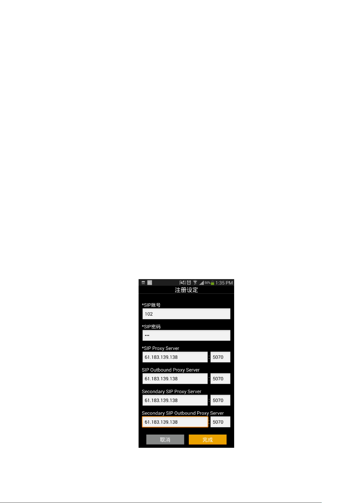
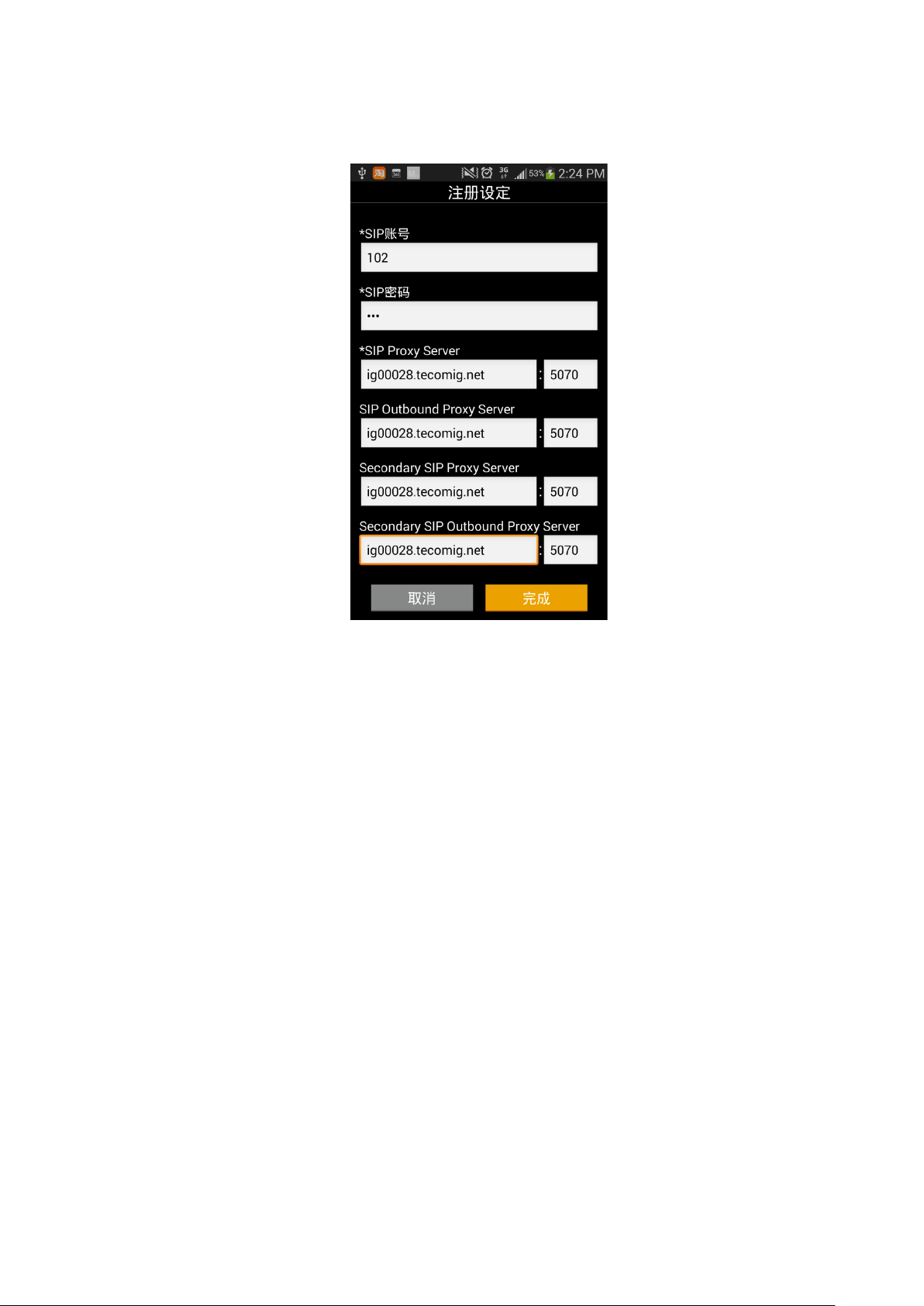
The IG7600 now supports remote registration for M22, M62 and M54(-i), this makes it
easier for users to configure their IP Phones from WAN Side.
IG allows Remote IP Phone to do registration under these circumstances (take M54 for
instance):
1 IG’s WAN side works under static mode, and has a public IP Address that we can
reach from anywhere. Just input the public address in corresponding blanks.
Copyright 2013 Tecom, Co. LTD. All rights reserved Page 16 of 127
Page 23
IG7600 Administration Manual
2 IG has a domain name that we can reach, users can set their IP Phones Sip server s
to the domain name as below.
3.31 Service Mode
IG7600 provide Day and Night settings for each weekday in service mode page. It will be
applied in the following function:
- Answering Position: Trunk incoming call may be forwarded to different extensions
according to the settings.
- Class of Service (COS): Phone extension may be assigned to have the different
COS in the different time.
- AA Greeting message in Working mod e.
3.32 Station Message Detailed Recording (SMDR)
The feature allows the admini str ation t o track all incomi ng and outgoi ng outs ide c all t raf fi c,
chronologically by extension number. SMDR is output from the standard Syslog
(None/LAN/WAN/Both)
SMDR information includes Trunk Line used, extension number, time and date the call
was placed, number dialed, duration of the call.
IG7600 also provides Outgoing Call Duration Start Time to the PSTN call. It’s used to
start the record for the PSTN outgoing call.
Copyright 2013 Tecom, Co. LTD. All rights reserved Page 17 of 127
Page 24

IG7600 Administration Manual
3.33 System Speed Dial
IG7600 stores frequently dialed numbers. These Speed Dial Numbers are accessed for
dialing by the associated Speed Dial Directory Numbers. The Speed Dial Directory
Numbers are assigned in Numbering Table. The Speed Dial is only for outgoing calls.
IG7600 stores up to 100 Speed Dial Numbers. In the Speed Dial Number, it’s allowed to
store Phone number up to 20 digits in leng th. Call Restriction and Call Routing are applied
and extensions may utilize only those numbers allowed based on their extension COS.
3.34 S ystem Time & Date
The IG7600 system provides a built-in time clock to track System Time for reference in
certain features such as day/night service mode. This clock has the ability to
automatically adjust with network NTP server through internet.
The IG7600 also supports to use manual time setting. Because IG7600 doesn’t support
battery backup, the time setting may need to be reset when rebooting the IG7600.
System Time & Date can be applied to Smart Phone and IP Phone.
3.35 Trunk Group
The Trunk Group feature is used to assign each PSTN Trunk and IP Trunk to a specific
Trunk Group. Each Trunk can be assigned to only one Trunk Group. The Trunk group
assignment is used for Trunk pool access. If setting some PSTN trunks and some IP
trunks into the same Trunk Group, the trunk access sequence will depend on the access
priority and the search order. The IG7600 provides up to 4 selectable Trunk Groups. All
PSTN Trunks and IP Trunks are assigned to Trunk Group 1 by default. For the four
groups you can choose IP first or PSTN first if programming PSTN and IP Trunk in the
same group. This will take effect if call routing entry’s destination has been set as Group
choice
Group All is a special group that all trunks are included in.
3.36 UCD (Uniform Call Distribution) Group (or Hunt Group)
IG7600 supports 4 UCD Groups. Each UCD Group can have up to 50 members. There
are three kinds of UCD Group mode – All Ring, Linear, and Distributed. For All Ring
mode, incoming Trunk cal ls r ing all member e x tensions simult aneou sl y. F or Linear mode,
incoming call is put into a queue and then distributed from the first extension. For
Distributed mode, it is the same as Linear but selection of an extension is uniformed.
If more than one call rings at the same time, the first agent to go off hook will be
connected to the call that has been ringing the longest.
For unanswered Trunk call, it will be forwarded to a Reroute destination. The Reroute
destination can be AA Menu, Voic e Mail , Pho ne Ex tens ion or Virtual Extension.
The missed UCD Group calls are recorded in UCD Call Log. It records the last 100
missed UCD Group calls.
3.37 IGW Group
IG7600 can discover other IG dynamically to build up an IGW Group. You can use IGW
Group as a call routing way to expand your voice system conveniently.
Copyright 2013 Tecom, Co. LTD. All rights reserved Page 18 of 127
Page 25

IG7600 Administration Manual
Basically in one IGW Gr oup we demand one o f the IGs works unde r mast er mod e, oth ers
work under slave mode. The members in the group need to be found by each other on
the internet make sure about it before you use this function. When an IGW Group is build
up successfully we can choose IGW Group as a Call Routing way in Call Routing
configuration page.
When IGW Group Settings are OK and Call Routing table is set appropriately, Ext under
one IG can call another IG’s Ext or use its Trunk resource directly. IG W Group only
supports Exts from different IG having conference call only when the Initiator is a specific
IP Phone, M54(-i) is not supported.
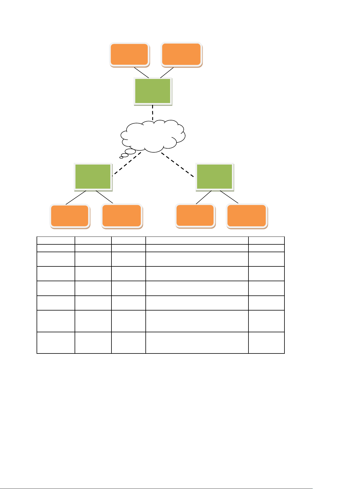
1. We have a figure and a table to describe what IGW Group supports .
Copyright 2013 Tecom, Co. LTD. All rights reserved Page 19 of 127
Page 26
IG7600 Administration Manual
IG-A
IG-B
IG-C
Operation
Support
Entity-1
Entity-3
Entity-1 call/hold/retrieve Entity-3
V
Entity-1,
Entity-2
Entity-3
Entity-1 transfer/forward Entity-2 to
Entity-3
V
Entity-1,
Entity-2
Entity-3
Entity-1 transfer/forward Entity-3 to
Entity-2
V
Entity-1
Entity-3,
Entity-4
Entity-1 transfer/forward Entity-3 to
Entity-4
V
Entity-1
Entity-3
Entity-5
Entity-1 transfer/forward Entity-3 to
Entity-5
V
Initiator:
an IPP
Entity-3
Entity-5
Three of them having a confer ence
V
Initiator:
SMP
Entity-3
Entity-5
Three of them having a confer ence
X
Internet
IG-A
Entity-1
Entity-2
IG-B
Entity-3
Entity-4
IG-C
Entity-5
Entity-6
Entity-1 is
Entity-1 is a
call
call
2. IGW Group doesn’t support:
a) Setting other IG’s Ext as a UCD/ Paging Group member.
b) Setting other IG’s Trunk line as a Trunk Group member
c) Listen to other IG’s Ext’s message.
d) Dial other IG’s Operator Code。
e) Set other IG’s Ext as operator.
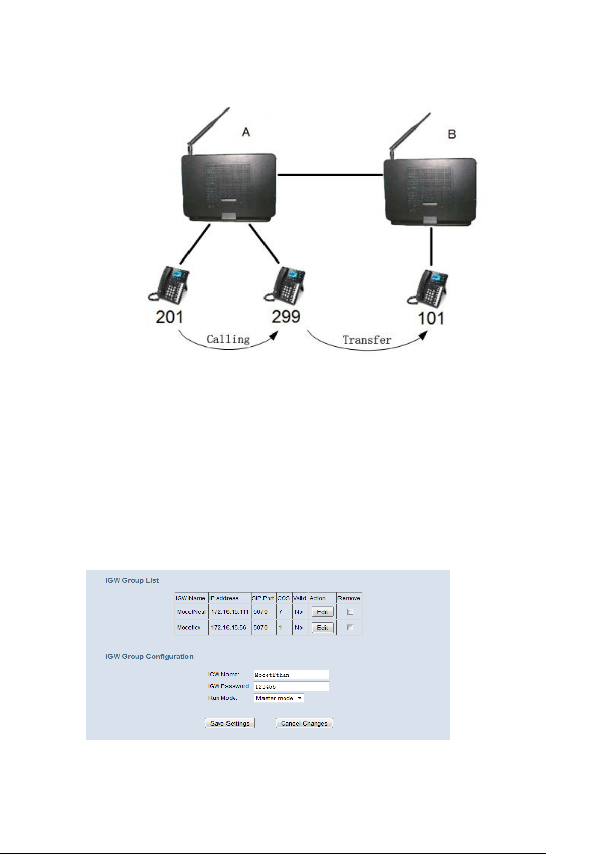
Usage Sample: IG A and IG B build up a IG W Group. IG A’s extension r ange is 201-299. IG
B’s extension range is 101-1 99. I G A has an IP Pho ne Ex t w hose number is 2 01 and a F XS
Phone whose number is 299. IG B has an IP Phone Ext whose number is 101.
Copyright 2013 Tecom, Co. LTD. All rights reserved Page 20 of 127
Page 27
IG7600 Administration Manual
With this setting I G A’s Ext 299 can transfer a call from 20 1 to IG B’s Ext 101 by di al i ng 101
directly.
Get Ready
[IG7600 programming—IGW Group]
IGW Name: The name of IG. It will be referred for the other IGs.
Run Mode: The mode that IG is running. IG can run in Master Mode or Slave Mode.
Master Mode: When IG is running in master mode, it maintains an IG list table. When the
master found that some slave IG changes its name or IP address, it will broadcast to all of
other slave IGs in this list and let them update their own IG list table.
Slave Mode: When IG is running in slave mode, the master IG IP address should be
configured. When its name or IP address changed, it will inform the master IG. And then the
master IG will let other IG know this change.
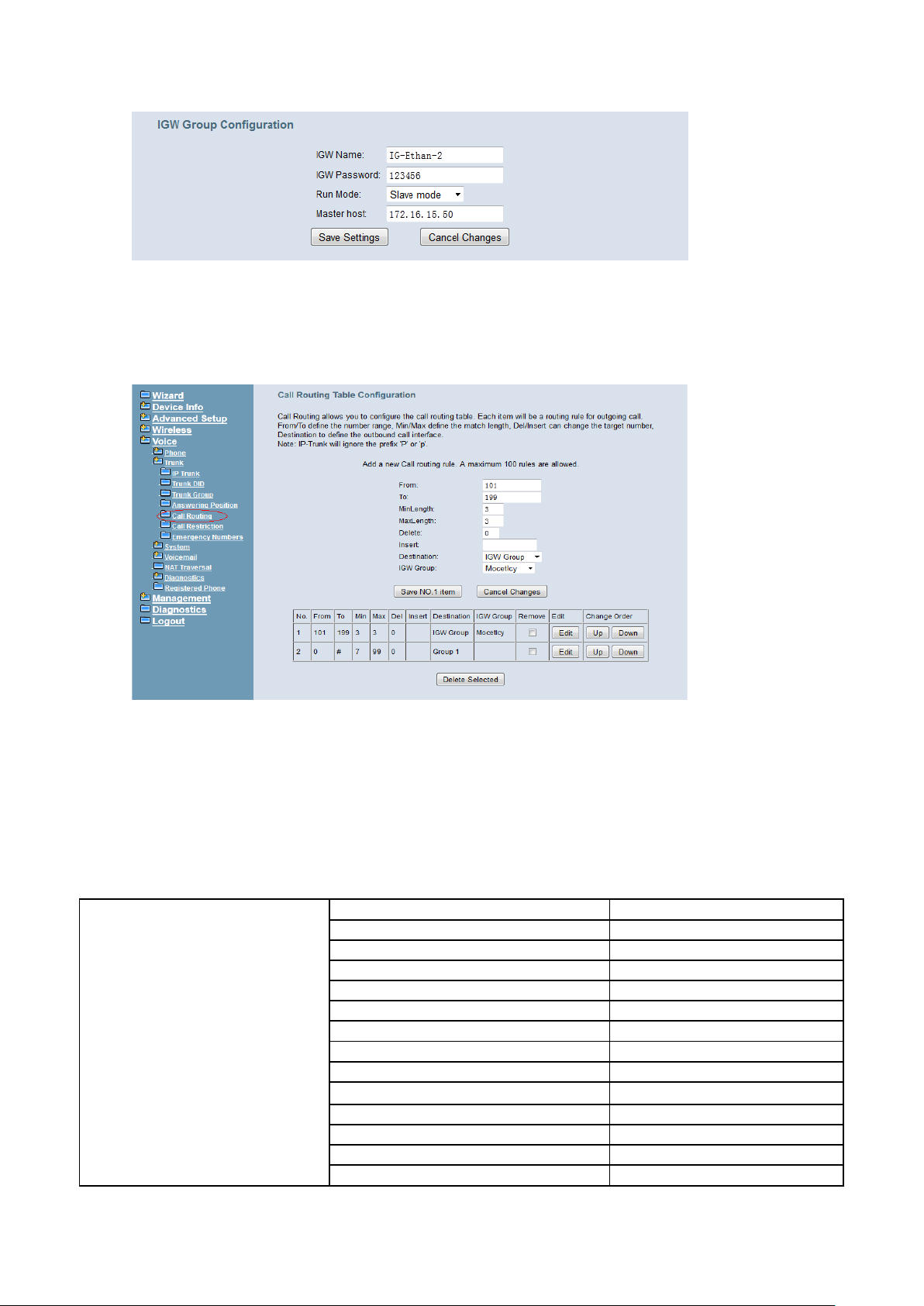
Slave mode:
Copyright 2013 Tecom, Co. LTD. All rights reserved Page 21 of 127
Page 28
IG7600 Administration Manual
3-Way Conferenc e
No
Access Control for Web Page
NA
Answering Position
No
Auto Attendant
No
Voice M ail
Yes
Basic Call
Yes
Call By Name
No
Call Abandon
Yes
Call Operator
No
Call Pickup – Group
No
Call Restrict io n
Yes
Call Routing
Yes
Caller ID Detection/Generation
Yes
Class Of Service (COS)
Yes
[IG7600 programming—Call Routing Rule]
To fulfill the condition of the Sample, IG A has one Call routing rule to IGW Group
member -- IG B whose setti ng s ar e l i ke this figure shows: when the di al i ng i s from 101
to 199 and is exac tly a 3 di gi t nu mber , IG A Trans fer the dial ing t o I G B di rect ly w ithout
deleting any of the digit.
Steps
Access IG B from IG A’s Ext
a) Off-hook the phone 201 and dial 299.
b) Pickup FXS 299 to answer the call.
c) Phone 201 pres s “transfer” button to hold the call
d) Phone 201 dial “101” and back to idle screen.
e) Ext 101 rings and pickup it to speak with Ext 201.
Features that support IGW Group:
IG7600 V oice General Features
Copyright 2013 Tecom, Co. LTD. All rights reserved Page 22 of 127
Page 29

IG7600 Administration Manual
Daylight Saving T ime
No
Default Set
No
Direct In Di a ling (DID)
No
Direct Inward System Access (DISA)
No
Emergency Call
No
Extension Password
NA
Fax/Modem
No
Flash – Analog Port (SLT) Flash
Recognition
Yes
IP Trunk
Yes
Message Wa iting Indication (M WI)
Yes
Music on Hold
Yes
Numbering Plan
No
PSTN Backup
NA
Registration Server
No
Service Mode
No
Stat ion Message Detailed Rec or di ng
(SMDR)
Yes
System Spe ed Dial
No
System Time & Date
No
Trunk Group
No
UCD (Uniform Call Distr ibution)
Group (or Hunt Group)
No
Wizard Setup
NA
3-Way Conferenc e
Yes
Agent Log On/Of f – UCD Group
No
Alphanumeric Display
Yes
Automatic Callback Busy
No
Auto Hold
Yes
Call Fork
No
Call Forwar d
Yes
Call Hold
Yes
Call Log
Yes
Call Park / Call Par k Answer
No
Call Pickup – Individual
No
Call Waiting
Yes
Caller Blocking
Yes
CO Flash
Yes
COS Following
No
Distinctive Ringing
Yes
Do Not Disturb (DND)
Yes
DSS/EDM
No
Feature Button Reset
NA
Feature Key Programming
NA
Feature Reset
NA
Hold Remind er
Yes
Hotline
Yes
Live Recording (One Touch Recor d)
Yes
Multi-Line Appearance
No
Mute
Yes
On Hook Dialing
Yes
Paging (All/Group) / Pagin g Answer
No
Paging Allow/Deny
No
IG7600 V oice Extension
Features
Copyright 2013 Tecom, Co. LTD. All rights reserved Page 23 of 127
Page 30

IG7600 Administration Manual
Phone Book
No
Phone Lock/Unlock
No
Plug & Play
NA
Reminder Tone
NA
Service Mode Switching
NA
Transfer / Recall
Yes
Volu me Contro l
Yes
Web Management
NA
3.38 Wizard Setup
The IG7600 has a setup Wizard that provides the system administrator with a series of
step-by-step operations. You can get in the wizard process from the entry shown on the
main page.
When you start setup wizard you can configure the corresponding settings step by step.
The following four items are supported.
• WAN Setting
• Secondary WAN Setting
• LAN Setting
• Wireless Basic
• Internet Time (include Manual Time Setti ng )
Copyright 2013 Tecom, Co. LTD. All rights reserved Page 24 of 127
Page 31

IG7600 Administration Manual
SIP Phone
Agent Log On/Off – UCD
Group
Yes
Yes
Yes
No
No
3-Way Confer ence
Yes
Yes
No
Yes
No
Alphanumeric Display
Yes
Yes
Depends
Yes
Depends
Automatic Callback Busy
Yes
Yes
No
No
No
Auto Hold
Yes
Yes
No
Yes
Depends
Call Fork
Yes
Yes
Yes
No
No
Call Forward – Direct
Yes
Yes
Yes
Yes
Depends
Call Forward – Busy
Yes
Yes
Yes
Yes
Depends
Call Forward – No Answer
Yes
Yes
Yes
Yes
Depends
Call Forward – DND
Yes
Yes
Yes
Yes
Depends
Call Forward – Follow Me
Yes
Yes
Yes
No
No
Call Hold
Yes
Yes
Yes
Yes
Depends
Call Log
Yes
Yes
No
Yes
Depends
Call Park
Yes
Yes
No
No
No
Call Park Answer
Yes
Yes
Yes
No
Yes
Call Pickup - Individual
Yes
Yes
Yes
No
Depends
Call Waiting
Yes
Yes
Yes
Yes
Depends
Caller Blocking
Yes
Yes
No
No
Depends
CO Flash
Yes
Yes
Yes
No
No
Conference (3-way)
Yes
Yes
Yes
Yes
Depends
COS Following
Yes
Yes
Yes
No
No
Default Setting
Yes
Yes
Yes
Yes
Depends
Distinctive Ringing
Yes
Yes
Partial
Yes
Depends
Do Not Disturb
Yes
Yes
Yes
Yes
Depends
DSS/EDM
IP2061 Only
Yes
No
No
No
Feature Key Programming
Yes
Yes
No
No
No
Hold Reminder
Yes
Yes
Yes
No
Depends
Hotline
Yes
Yes
Yes
No
Depends
LCD & Interactive Buttons
Yes
Yes
No
Yes
Depends
Live Recording
Yes
Yes
No
No
Depends
Multi-Line Appearance
Yes
Yes
No
Yes
Depends
Mute
Yes
Yes
No
Yes
Depends
On Hook Dialing
Yes
Yes
Depends
Yes
Depends
Page (All/Group) - Paging
Yes
Yes
Yes
Yes
Yes
4. IG7600 Voice Extension Features
IG7600 follows SIP standard to serve SIP phones. Basically, telephone features that
meets SIP standard can be applied in IG7600.
Smart Phone M54(-i) , M22, M62 and IP2061 phone support many phone features. But
for adding some traditional KTS features that are not defined definitely in SIP protocol,
some specified i n for m ati on ar e transmitted between IG7600 and IP2061/M22/M62/M54(-i)
Phones. This secti on i ntroduc es these special phone features. Some features are only for
IP2061/ M22/M62/M54(-i) phones and/or FXS phone.
The following features dep end on w het her the phone pr ovides.
Feature IP2061 M22/M62 FXS M54(-i) Other
Copyright 2013 Tecom, Co. LTD. All rights reserved Page 25 of 127
Page 32

IG7600 Administration Manual
Page (All/Group) - Paged
Yes
Yes
No
No
No
Page Answer
Yes
Yes
No
No
No
Page Allow / Deny
Yes
Yes
No
No
No
Phone Book
Yes
Yes
No
Yes
Depends
Phone Lock/Unlock
Yes
Yes
Yes
Yes
No
Plug and Play
Yes
Yes
Yes
Yes
No
Reminder Tone
Yes
Yes
Yes
No
Depends
Service Mode Switching
Yes
Yes
Yes
No
No
Transfer
Yes
Yes
Yes
Yes
Depends
Web Management
Yes
Yes
No
No
Depends
Volume Control
Yes
Yes
Depends
Yes
Depends
NOTE: the word “Depends” means that the feat ures dep end on whether the phone
provides.
4.1 3-Way Conference
The Conference feature allows the user to connect two calls into a single conversation.
IP2061/M22/M62 can establish a 3-way conference on the phone. M54(-i) needs to use
IG7600’s resource to es tabl ish the 3-way conference c al l . IG 7 600 supports 1 se t o f 3-way
conference for M54(-i).
4.2 Agent Log On/Off – U CD Gro up
Extensions can log on or log off from UCD group.
Enable Agent Log On feature, dial *91.
Disable Agent Log On feature, dial **91.
If an extension disables the Agent Log On feature, the extension should log off from all
UCD groups it belongs to.
4.3 Alphanumeric Display
The IP Phone extension provides a graphic LCD that supports 64 alphanumeric
characters. The LCD enhances many system features.
4.4 Automatic Callback Busy
IP2061/M22/M62 supports Automatic Callback Busy. When the callee has no session
resource, the caller will hear busy tone.
The caller can dial “6” to get the Automatic Callback Busy feature.
The confirmation tone will be heard and come back to idle status. When the callee is no
longer in busy status, the caller will hear call back ring.
Remove the Callback Busy calls, dial *66.
Example:
To make it simple and clear, assume that we have 3 EXTs under our system. Let’s
call them A, B and C. A is an EXT with Call Waiting function disabled.
Now A is having a conversation with B, C wants to call A, after the dialing, user C
hears the busy tone, shows that A cannot answer the call now. Before the busy tone
stops C presses “6” to enable busy call back, and then C hangs up.
Busy Call Back works like this, when EXT A turns back to idle (hang up the call with
B), EXT A will starts to ring immediately, after A picks up the cal l, Ex t C starts to ri ng,
and C picks up the call to start the conversation with A.
Copyright 2013 Tecom, Co. LTD. All rights reserved Page 26 of 127
Page 33

IG7600 Administration Manual
4.5 Auto Hold
You may enable the feature to simpl ify call handling and avoid accidental “lost” calls. H ol d
will automatically place any call that is currently connected at your phone on hold
whenever a Trunk line button is pressed.
4.6 Call Fork
IG7600 supports to ring another extension or an outside destination via IP Trunk
simultaneously when the extension gets an incoming call. When the call is answered by
one of the both parties, the call at the other party will stop ringing automatically.
For the Call Fork destination, IG7600 supports to have the second Fork destination. If
the first destination is non-existed or busy, make the forking call to the second Forking
Destination.
T o Ac tivate (Type: 0 – ICM, 1 – Outside, 2 – Both; Destination#: 1 – first, 2 – second)
*26 + Destination# + Type + Ext No
*26 + Destination# + Type + * + (PSWD) + * + Outside Number
To Cancel
**26 cancel the both forking destination.
**261 cancel the first forking destination.
**262 cancel the second forking destination.
Call Fork is not applied to Operator call, Paging call and UCD call
4.7 Call Forward
Call Forwarding rerout es inco mi ng call s fro m one extension to another destinat ion. The
destination of a c all for ward can be another extension, voicemail bo x or an outside phon e
number (External Call Forward; ECF).
IG7600 support the following featur e acc es s c odes to pr og r am Call Forwards for
IP2061/M22/M62/M54(-i) and FXS. It includes a “Type” setting for each Call Forward. It
can be programmed to “ICM”, “Outside” or “Both” (Type: 0 – ICM, 1 – Outside, 2 – Both).
Direct Call Forward:
Forward all of the calls without regard to the extension status.
To enable, dial *21 + Type + Ext/VAA/UCD No.
*21 + Type + * + (PSWD) + * + Outside Number
To disable, dial **21.
Busy Call Forward:
Forward the calls if the extension is busy.
To enable, dial *22 + Type + Ext/VAA/UCD No.
*22 + Type + * + (PSWD) + * + Outside Number
To disable, dial **22.
No Answer Call Forward:
Forward the cal ls if the extensio n doesn’t answer the c all within No Ans wer Time.
To enable, dial *23 + Type + Ext/VAA/UCD No + * + Time.
*23 + Type + * + (PSWD) + * + Outside Number + * + Time
To disable, dial **23.
DND Call Forward:
Forward the calls if the extension enabled DND.
To enable, dial *24 + Type + Ext/VAA/UCD No
Copyright 2013 Tecom, Co. LTD. All rights reserved Page 27 of 127
Page 34

IG7600 Administration Manual
*24 + Type + * + (PSWD) + * + Outside Number
To disable, dial **24.
Follow Me Call Forward:
Forwards calls at your extension to the extension where you are currently
working.
To enable, dial *25 + Type + Ext No + * + Password
To disable, dial **25 + Ext No + * + Password
These Call Forwar d fe atur es can also be set / cancelled in w eb page of IP 2061/M22/M62.
4.8 Call Hold
Trunk and Interco m calls can be placed on hold at any extension. Any PSTN/IP line caller
placed on hold will hear the Music On Hold. The held trunk can be resumed by other
extensions by pushing Feature Key.
For the Single Line phone, it’s to put a call on hold, press flash then hang up (optional).
It’s to return to the original call, press flash or pick up the phone.
4.9 Call Log
The IP2061/M22/M62 and M54(-i) phone can store a call log for your reference. To
access your call log, use the LCD menus. There are three types of Call Logs - Missed
Calls, Received Calls, or Dialed Calls. To dial from a listing, press the soft keys
corresponding to the LCD menus display.
4.10 Call Park / Call Park Answer
The feature allows you to “park” a call at IP2061/M62 extension. It also allows any
extensions to retrieve a parked call. Calls are parked by pressing the Park feature key.
System supports two methods in the Call Park application.
a. If the Park key has a specified Call Park number, like 731, then it’s called System Call
Park key. For example, a PSTN trunk call 701 is “parked” by a System Call Park key
731, then all System Call Park key 731 and all Trunk key 701 on all extensions will
flash.
Any extension can pi ck up the t r unk call by pres sing the fl ashing Sy stem P ark key 73 1,
by inputting the Call Park Code 731, by pressing the flashing Trunk key 701, or by
inputting the Trunk Access Code 701.
b. If the Park key has no Call Park number, then it’s called Individual Call Park key. For
example, a PSTN trunk call 701 is “parked” by extension 101’s Individual Call Park
key, then only Trunk key 701 on all extensions or the Individual Call Park key on
extension 101 will flash, all extensions’ System Call Park key and other extensions’
Individual Call Park will NOT flash.
Extension 101 can pick up the trunk call by pressing the flashing Trunk key 701, by
inputting the Trunk Access Code 701, or by pressing the flashing Individual Call Park
key.
Other extensions can pick up the trunk call by pressing the flashing Trunk key 701 or
Copyright 2013 Tecom, Co. LTD. All rights reserved Page 28 of 127
Page 35

IG7600 Administration Manual
by inputting the Trunk Access Code 701. Meanwhile, other extensions can also pick
up this trunk call by pressi ng the I DLE I ndiv i dual Cal l Park key and in put t he ex tensi on
number “101”.
4.11 Call Pickup – Individual
You may answer the calls at another specified extension. The feature allows you to easily
access calls ringing via the feature access code.
*53 + Extension Number
4.12 Call Waiting
If Call Waiting is enabled for a specific IP2061/M22/M62/M54(-i) station, an alert (muted
ring) will be play ed on the called party w hen a second cal l is rec eived and t he extensi on is
in use.
To enable Call Waiting, dial *98
If Call Waiting is disabled for a specific station, the station will return a busy tone to any
calling party while the station is in use.
To disable Call Waiting, dial **98
PS: Call waiting is disabled by default. You have to enable it manually.
Call waiting tone is enabled by default.
4.13 Caller Blocking
IP2061/M22/M62 can block up to 10 phone numbers from reaching you at your phone
when a caller attempts to call you from one of these numbers.
4.14 CO Flash
FXO Line is programmed setting that will determine what flash timing will be presented to
the CO/PBX when the extension issues a Hook-Flash command while connected to a
FXO Line.
4.15 COS Following
You can temporarily change the individual Class of Service of each extension on a per
call basis. You may want to do this when the user goes to the office of low-priority COS
extension and try to make an outgoing call, the user can use the functi on to use their own
COS.
When using the COS Fol l owing feature the st at ion COS change will revert to the station’s
original COS after a one minute idle time-out.
To set COS Following, dial *55 + (phone number) + (password)
4.16 Distinctive Ringing
Distinctive ring cadences can be selected allowing adjacent users to discern which
extension is ringing. It also provides different ring tones for intercom and trunk calls.
Every Trunk Line may be allocated one of the available Ring Types. When the feature is
used, the specific ring type assigned to the Trunk Line is the ring type heard when the
Trunk Line rings. The feature helps to identify the Trunk Line and the Trunk Group to
which it belongs to.
Copyright 2013 Tecom, Co. LTD. All rights reserved Page 29 of 127
Page 36

IG7600 Administration Manual
4.17 Do Not Disturb (DND)
Extension users can enable DND to reject all incoming calls. The DND on an extension
can be allowed or denied through the feature access code.
To enable the Do Not Disturb feature, dial *4.
To disable the Do Not Disturb feature, dial **4.
DND and FWD can be s et indep endentl y. If multipl e featur es are s et at the same ti me, it is
applied in the order of Direct FWD > DND > Busy/No Answer FWD.
4.18 DSS/EDM
IG7600 support s to pro v ide the s t atus o f the e x tensions and trunk li nes. The s t at us c an b e
shown on the LED of IP2061/M22/M62’s flexible keys. For IP2061, M22 and M62, they
support EDM modules that can have 24 more keys .
PS: basically the button lamp will light when the button’s corresponding
destination is busy, but when the destination is an M54(-i), the lamp will not lit
under the same circumstance.
4.19 Feature Button Reset
The feature is used to reset all feature buttons to be the same as the current settings in
IG7600.
To reset the Feature Buttons, dial *68 + (Password)
4.20 Feature Key Programming
Feature Keys can be programmed by phone users. A feature key can be programmed for
line appearance.
To program a Feature Key, dial *70 + (Feature K ey num ber : 01 – 04/44
Key T y pe; 00 - 08) + Number
Feature Key Type:
00: Null; Number should be null.
01: Extension; Number can be an Extension or Virtual number.
02: Trunk; Number can be a PSTN, IP Trunk or Trunk Group number.
03: Call-Park; Number can be a Park number.
04: Feature Key; Number can be a feature access code
05: Others; Number could be an outside phone number.
06. Do Not Disturb; Number should be null.
07: Live Record
08: Virtual Mailbox key; Number can be a Virtual number.
(*)
) + (Feature
Note: IP2061, M22 and M62 supports EDM module, it provides 24 more keys for feature
access.
4.21 Feature Reset
When the feature is activated, the extension will return the features that can be
programmed through feature codes to default settings. It will affect the following options:
Call Waiting disabled
Call Waiting Tone Enabled
Copyright 2013 Tecom, Co. LTD. All rights reserved Page 30 of 127
Page 37

IG7600 Administration Manual
Paging Accept
Default Feature Key Setting
Phone Lock disabled
Call Forward (Direct, Busy, No Answer, DND, Call Fork) disabled
DND disabled
Agent Log on
Auto Answer disabled
Distribution List clean
To activate the Default Setting feature, dial *69+ (Extension Password or Administrator
Password).
4.22 Hol d Remi nde r
IP2061/M22/M62 provides a programmable timer to remind you that a call has been left
on Hold. When enabled, you will hear one ring tone repeated each time the selected hold
time expires.
4.23 Hotline
The feature allows an extension to automatically access a given resource each time the
extension goes off hook. The resource can be any system directory number or outside
phone number. It can access the desired resource from 0 to 8 seconds after the
extension goes off hook. The delay allows the user to dial another resource before the
hotline takes effect.
If the “Hotline Delay Time” of FXS is 0, it can cancel the setting by pressing Flash key
after making a hotline call. Then dial the feature access code.
To enable, dial *9* + (any Number) + * + Time //Time: 0~8 seconds; 0: immediately
To disable: **9*
4.24 Live Recording (One Touch Record)
The Live Recording feature can be activated by using the Live Recording feature key on
your telephone. When activated during an active call, the Live Recording feature will
record the conversation as a voicemail message. After finishing the recording, the
recording will be as a new leaving message into the extension’s mailbox.
During the recording , t he LED of th e Liv e Rec ording key is lit. Press the key w hen it’ s li t, it
will stop the recording. When the call is held or released, it stops the recording also. After
stopping the recording, it disallows to enable it again in 10 seconds.
It allows having 4 Voice Recording calls maximum simultaneously. The maximum
recording time is 30 minutes. Live Recording feature isn’t applied in the conference call.
4.25 Multi-Line A ppearance
IG7600 provides PS TN l i ne and IP l ine s t at u s t o IP2 061/M22/M62, it also prov i des P S TN
line or IP Line status to M54(-i).
Trunk LED:
Dark – the line is Null or Idle
Fast Flash – the line is ringing
Slow Flash – the line is held
Copyright 2013 Tecom, Co. LTD. All rights reserved Page 31 of 127
Page 38

IG7600 Administration Manual
Wink Flash – the line is held recall
Lit – the line is in talk
4.26 Mute
The Mute feature allows the user to disable the handset transmitter or the speakerphone
microphone.
4.27 On Hook Dialing
IP2061/M22/M62 phone extensions may make outgoing calls without lifting the handset
and monitor the dialing status through the built-in speaker. The button lamp is lit when
dialing.
4.28 Paging (All/Group) / Paging Answer
Paging function can be initiated from any extension in the IG7600. Dialing a Paging
Group Directory number allows an extension to broadcast a page to all assigned
members of the selected paging group.
IG7600 provides a Paging Range to define the paged extensions.
- LAN: the all assigned extensions on LAN side are paged.
- WAN: the all assigned extensions on WAN side and the extensions are connected
to the same router with IG7600 are paged.
- Both: the all extensions on LAN and WAN are paged.
When receiving a Paging call, the paged IP2061/M22/M62 extension can answer the call
by pressing the “Answer” soft button.
IG7600 provides 3 Paging Group. Each Group can have 49 extensions.
4.29 Paging A llow/Deny
You can block one-way pages (internal, group, and all page) over the IP phone speaker
by dialing the Page Deny code.
To enable Paging Deny, dial *99
To disable Paging Deny, dial **99
4.30 Phone Book
The IP2061/M22/M62/M54(-i) provides users with a Phone Book, with each entry
containing a user programmed Phone Number and User Name. You can also edit your
Mobile Number and Display Name on an M54(-i).
4.31 Phone Lock/Unlock
You can use the Lock feature to prevent unauthorized trunk calls from being made from
extension. A locked extension continues to receive incoming calls, and a user can
continue to place and receive intercom calls. Outgoing Trunk calls are blocked.
To lock the phone, dial *97 + (Password)
To unlock the phone, dial **97 + (Password)
Copyright 2013 Tecom, Co. LTD. All rights reserved Page 32 of 127
Page 39

IG7600 Administration Manual
4.32 Plug & Play
While connecting IP2061/M22/M62 to IG7600’s LAN port, it will register to IG7600
automatically. IG7600 will also assign a valid extension number to the phone directly.
When IP2061/M22/M62 and IG7600 connect to the same Router, IG7600 will assign a
valid extension number to the IP2061/M22/M62 also.
IG7600 will do Plug & Play with M54(-i) only when the pairing button is pushed.
4.33 Re mi nder Tone
Play stutter dial tone to remind the user that DND or DCFW is enabled at your extension.
If having MWI, it also plays the stutter dial tone
4.34 Service Mode Switching
The feature can be us ed by Operat or ph on e only . Oper ator us es a pr ogr ammed k ey or by
feature access code to change IG7600 Service Mode.
*791: assign to Day mode.
*792: assign to Night mode
*793: assign to Time mode
IG7600 also provide a feature code “*790” to switch the Service mode. The rule is
- If “Service Mode” setting is “Day”, it changes the setting to “Night”.
- If “Service Mode” setting is “Night”, it changes the setting to “Day”
- If “Service Mode” sett in g is “ Time”, i t c hang es the Ser vi ce Mode te mporar ily . The
change will be clean when it reaches the time in “Time” service mode.
When the “*790” is programmed on the line key, it shows the current operating mode on
the LED indication (the LED is lighten on Night time, dark on Day mode).
4.35 Transfer / Recall
Transfer is used to deli v er cal ls at y our extens i on to another ex tensi on. I t means tha t call s
can be routed to IG7600’s system destinations: an extension or an outside phone
number.
When transferring a trunk call to another extension, if the call is not picked up within 30
seconds, the call will be recalled back to the transferring extension.
IP2061/M22/M62/M54(-i) Phone supports Blind Transfer, Unscreened Transfer, and
Screened Transfer.
FXS phone supports Unscreened Transfer, and Screened Transfer.
4.36 Volume Control
The IP2061/M22/M62 is equipped with a volume control that is used to adjust the various
volume settings of the telephone. The following functions can be adjusted:
• Ringing
• Handset
• Speaker
• Headset
Copyright 2013 Tecom, Co. LTD. All rights reserved Page 33 of 127
Page 40

IG7600 Administration Manual
4.37 Web Management
The IP2061/M22/M62 is supported two-level web management. The Administrator has
several pages to co nfigur e the IP pho ne. Us er is able t o config ure per sonal in formati on by
himself. User level is not including these two pages – software update, SIP configuration.
Copyright 2013 Tecom, Co. LTD. All rights reserved Page 34 of 127
Page 41

IG7600 Administration Manual
5. Quick Installation
This Quick Installation helps you to install the product quickly and easily. For detailed
instructions on installation, and further setup option, please refer to the configuration
chapter.
5.1 Connecting the IG7600
(1) Place IG7600 in an optimum location.
(2) Connect the included Category 5 Ethernet network cable to the IG7600’s LAN port or
WAN port. Then connect the other end of the network cable to a switch or hub or
directly your PC’s Ethernet port. The IG7600 will then be connected to your
10/100/1000 network.
(3) Connect the AC power adapter to the IG7600’s Power port. Only use the power
adapter supplied with the IG7600. Use of a different adapter may result in product
damage.
(4) Now that you have connected the IG7600 to your network, you are ready to begin
setting it up. The Setu p Wizard w il l t ake y ou thr ough al l necess ar y s teps t o help y ou t o
configure the IG7600 easily.
5.2 Wizard Setup
This system administrator can configure the IG7600 remotely or locally via a Web
Browser. When IG7600 return to default factory settings, its LAN address is
“192.168.123.1”, and us ername is “ admin123 4”, passw ord is “adminxxxxxx” (”xxxxxx” are
the last 6 characters of IG’s MAC Address).
Click “Wizard” on IG ’s hom e page to start the setup w i zar d. It allows system administrator
to select the appropriate operation mode and configure the corresponding setting step by
step. The following four items are supported.
WAN Settings
Secondary WAN Settings
LAN Settings
Wireless Basic
Internet Time
In the configuration, the administrator presses “Next” or “Cancel” button to choose the
setting item. If pressing “Save & Reboot”, the settings will be saved and the IG7600 will
be rebooted automatic al l y .
5.2.1 WAN Setting There are three modes that you can configure WAN IP address: Static IP mode, DHCP
mode, and PPPoE mode. You can also select to enable or disable Firewall.
Note that Network Address Translation (NAT) function is de faul t enabled and is not
shown on the page to prevent it from being disabled.
This page shows that the current exist ing WAN interface i n this system is Static IP mode.
(Figure 5-1)
Copyright 2013 Tecom, Co. LTD. All rights reserved Page 35 of 127
Page 42
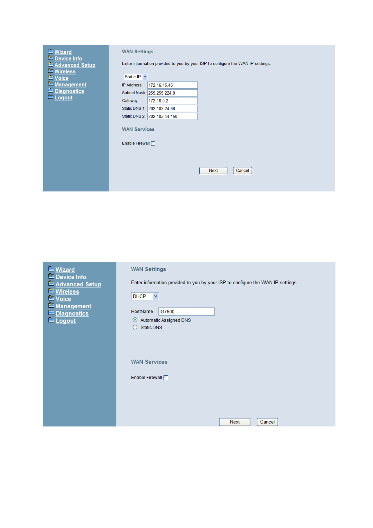
IG7600 Administration Manual
Figure 5-1. Wan Settings (Static IP mode)
The Dynamic Host Configuration Protocol (DHCP) is an Internet protocol for automating
the configuration of computers that use TCP/IP. DHCP can be used to automatically
assign IP addresses, to deliver TCP/IP stack configuration parameters such as the
subnet mask and default router, and to provide other configuration information.
This page shows the current existing WAN interface in this system is DHCP mode
(Figure 5-2).
Figure 5-2. Wan Settings (DHCP mode)
The Point-to-Point Protocol over Ethernet (PPPoE) requires a user name and password
that your ISP has provided to you to establish your connection. This page shows that the
current existing WAN interface in this system is PPPoE mode (Figure 5-3).
Copyright 2013 Tecom, Co. LTD. All rights reserved Page 36 of 127
Page 43
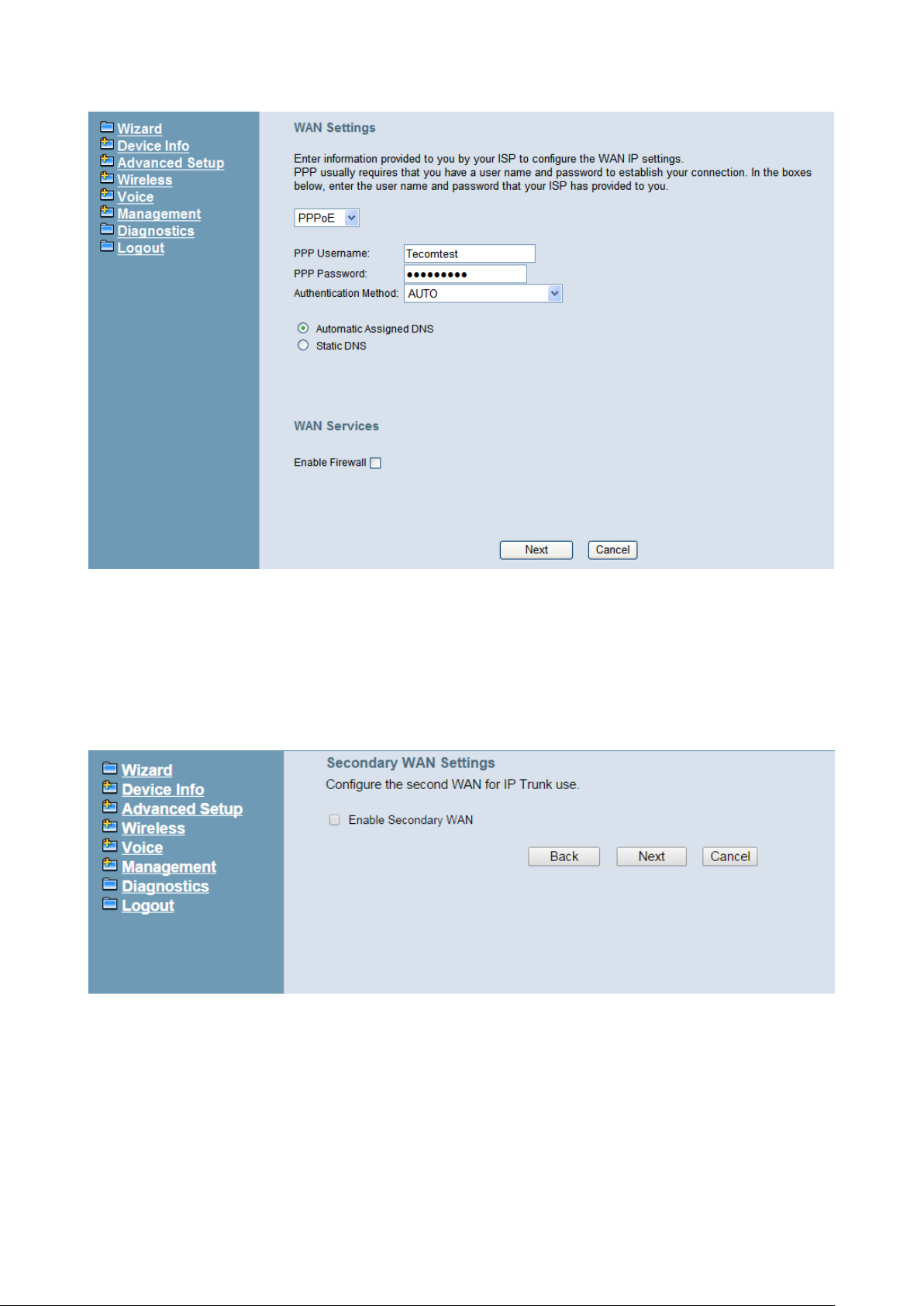
IG7600 Administration Manual
Figure 5-3. Wan Settings (PPPoE m ode)
5.2.2 Secondary WAN Setting
IG7600 supports secondary WAN which is dedicated for IP Trunk. If you check “Enable
Secondary WAN” then it will turn LAN port into secondary WAN port. And you sti ll can use
wireless interface for LAN access. Regarding secondary WAN settings, please refer to
5.2.1 WAN settings.
5.2.3 LAN Setting
This page (Figure 5-4) al l ows you giving LAN IP and Subnet Mask for LAN i nterface. You
can also select to enable or disable DHCP Server and configure related settings for that
mode.
Copyright 2013 Tecom, Co. LTD. All rights reserved Page 37 of 127
Page 44
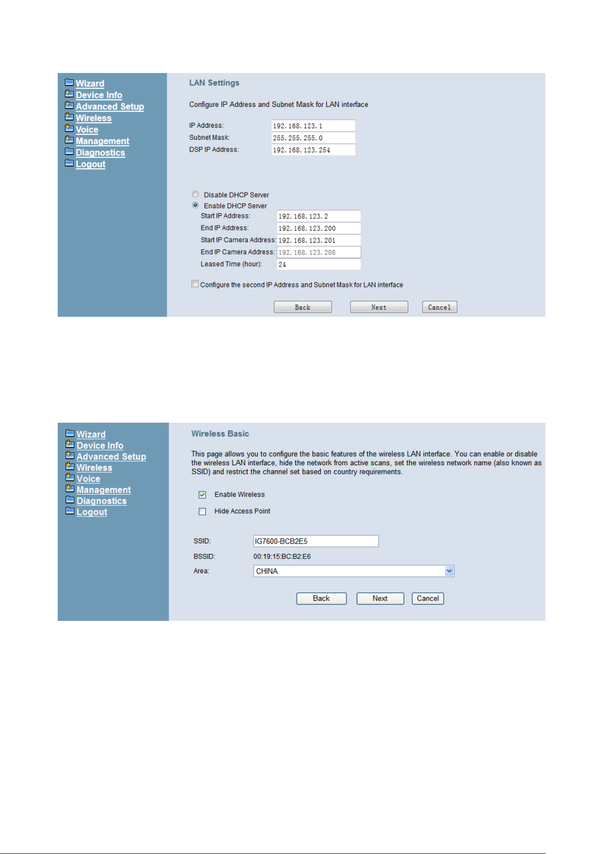
IG7600 Administration Manual
Figure 5-4. LAN Settings
5.2.4 Wireless Basic
The page (Figure 5-5) allows you to config ure basic feat ure o f th e w irel ess LAN i nter fac e.
You can enable or disable the wireless LAN interface, hide the network from active
scanning, set the wireless network name (also known as SSID), and restrict the channel
set based on country requirement.
Figure 5-5. Wireless Basic
5.2.5 Internet Time
The page allows you to configure the NTP time server, so the IG7600 can have correct
system time. It is useful such as reviewing the System Log. (Figure 5-6).
Copyright 2013 Tecom, Co. LTD. All rights reserved Page 38 of 127
Page 45
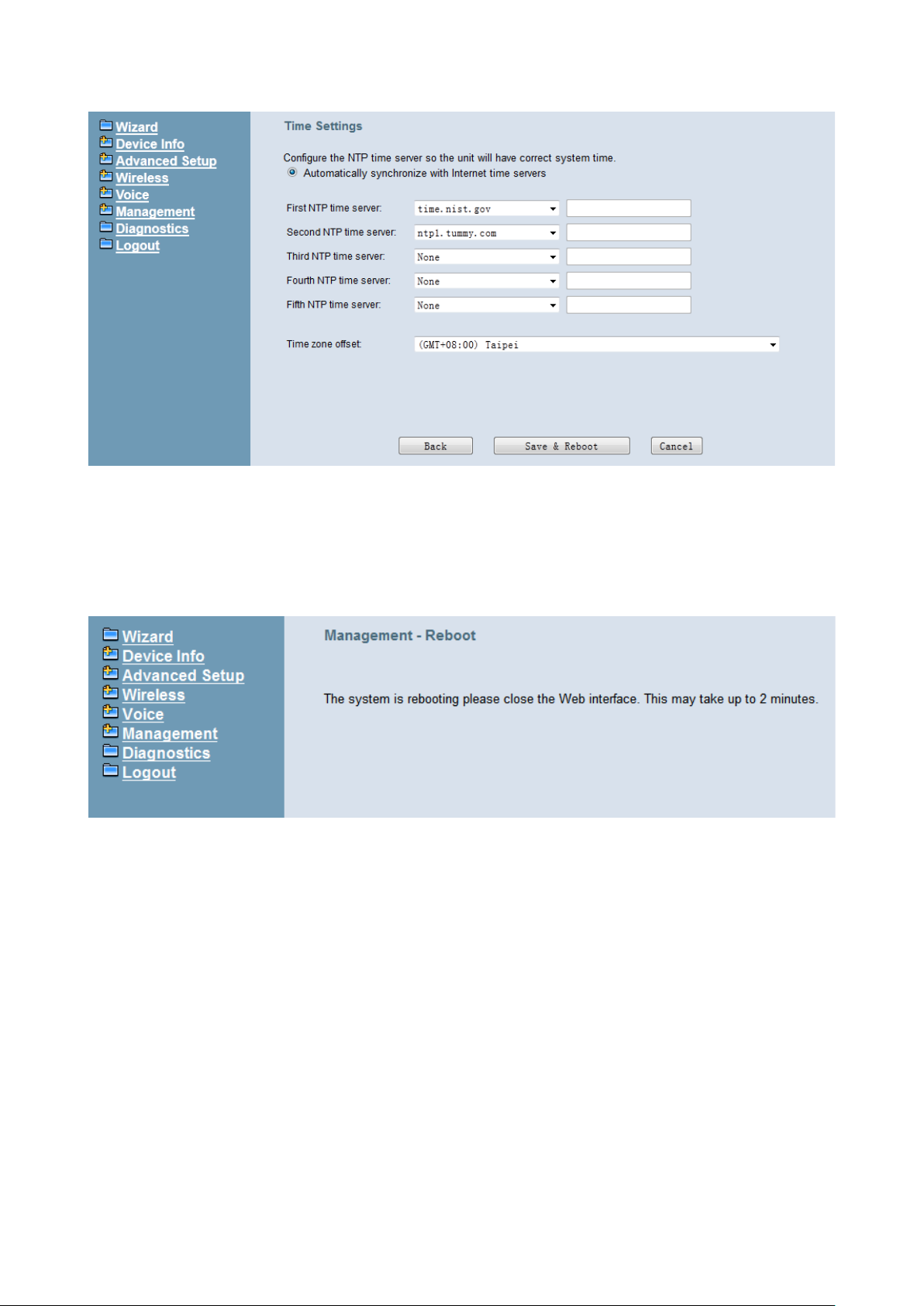
IG7600 Administration Manual
Figure 5-6. Internet T ime – Automatic
5.2.6 Wizard Setup Finished When you click “Save & Reboot” Button at above page, the wizard setup will save your
setting and the wizard setup will be finished. Then the system will reboot as shown
below.(Figure 5-7)
Figure 5-7. Wizard Setup finished
Congratulations! Th e wizard setup of the IG7600 is complete.
For additional details, advanced configuration, or any other questions , re fers t o the next
chapter.
Copyright 2013 Tecom, Co. LTD. All rights reserved Page 39 of 127
Page 46
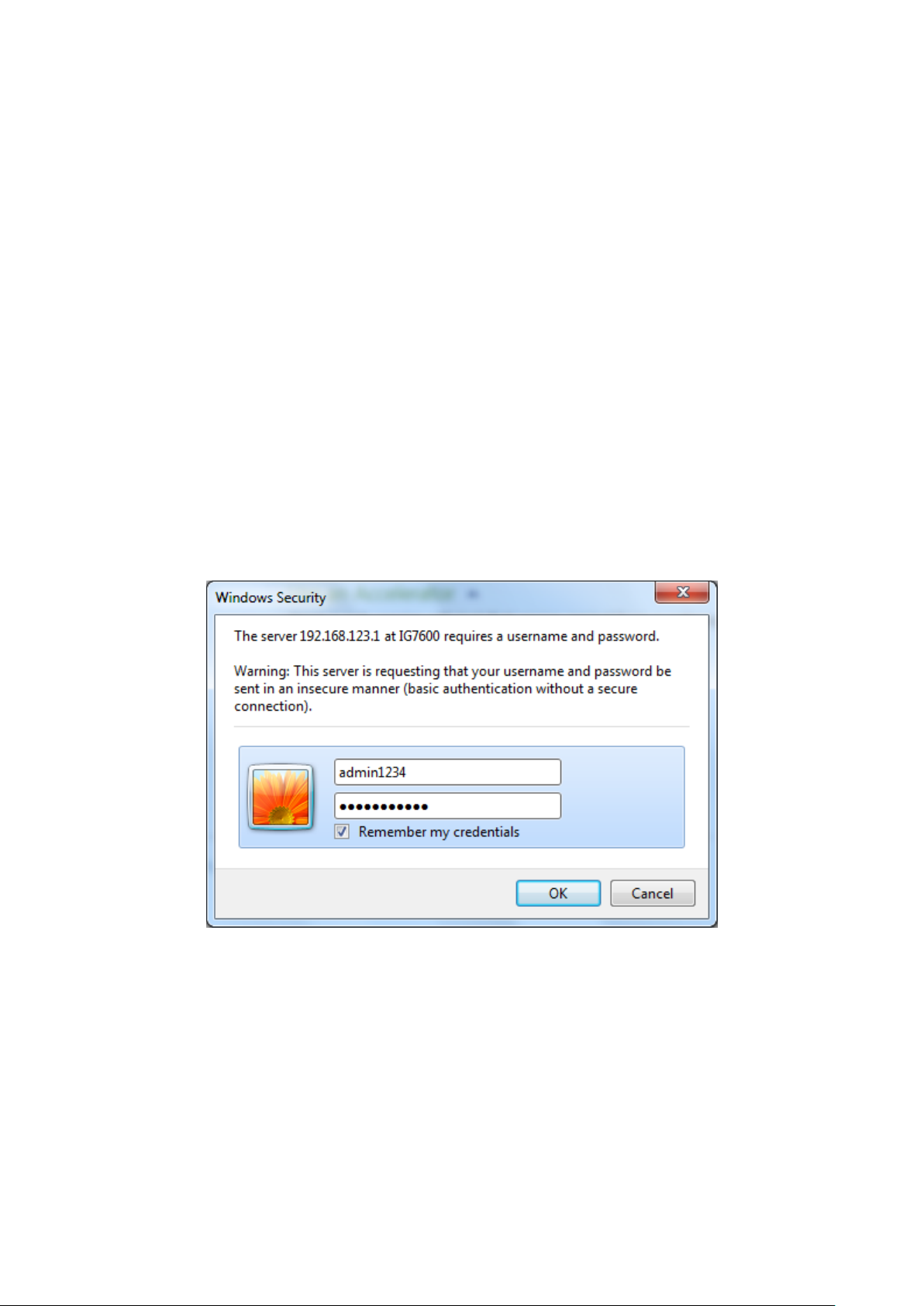
IG7600 Administration Manual
6. Configuration
6.1 Setup
Connect the IG7600 to PC.
The default LAN IP of the IG7600 is 192.168.123.1.
The default WAN IP of the IG7600 depends on upper router’s DHCP server.
For web login, the default user name is “admin1234”; the default pas sword is
“adminxxxxxx”. (”xxxxxx” are the last 6 characters of IG’s MAC Address.)
For telnet login, the name/password is the same as web login.
6.2 Establish the Connection
Enter the IP address of IG7600 from the Web Browser.
A Dialogue Box will pop up to request the user to enter username and password. (Figure
6-1)
Figure 6-1. Authentication
Please enter the management username/password into the fields then click the OK
button (default username/password is admin1234/adminxxxxxx. ”xxxxxx” are the last 6
characters of IG’s MAC Address.)
When the authentication is OK, the home page “Device Info – Summary” will be
displayed. In the Web Configuration, it is divided into eight categories (Figure 6-2):
Wizard
Device Info
Advanced Setup
Wireless
Voice
Copyright 2013 Tecom, Co. LTD. All rights reserved Page 40 of 127
Page 47
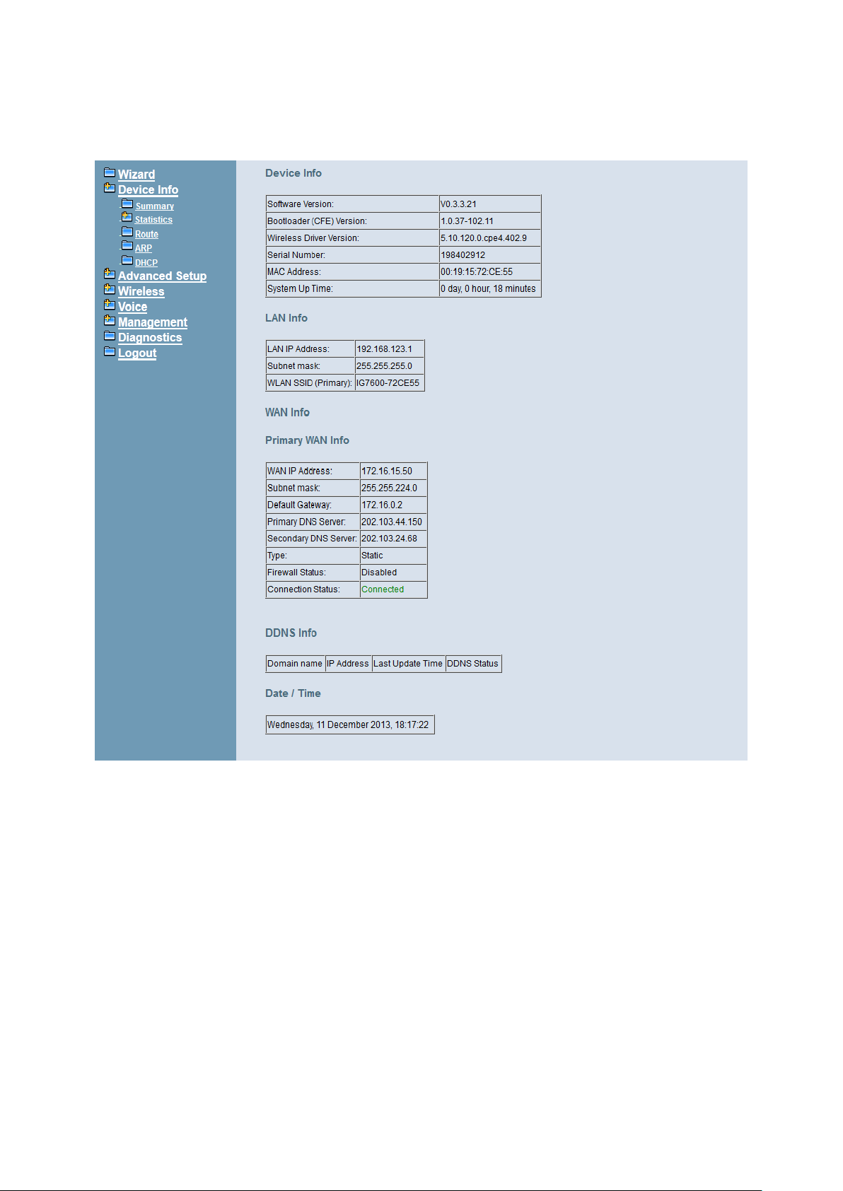
Management
Diagnostics
Logout
IG7600 Administration Manual
Figure 6-2. Device Info - Summery
Copyright 2013 Tecom, Co. LTD. All rights reserved Page 41 of 127
Page 48
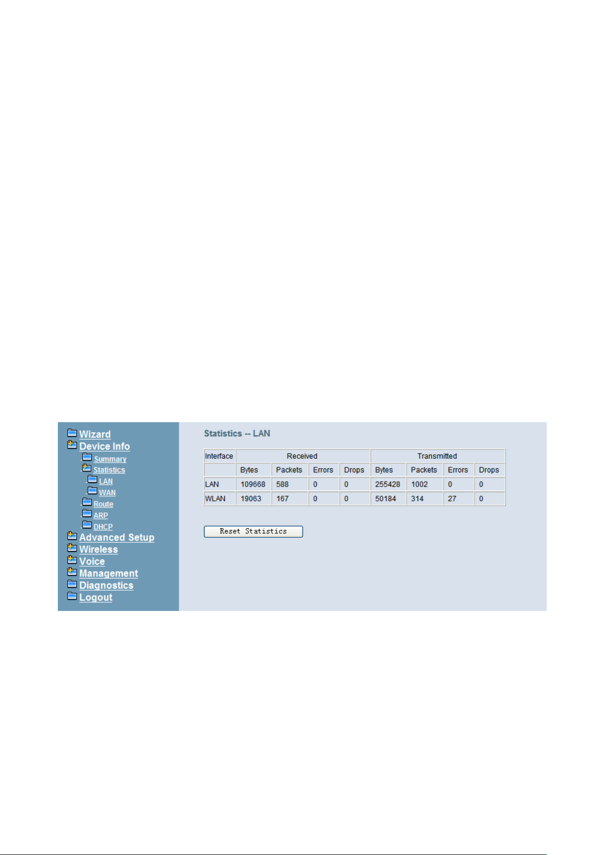
IG7600 Administration Manual
6.3 Device Info
This information re flects the c urrent St atus o f IG7600 con nection. I t incl udes the foll owing
topics:
Summary
Statistics
Route
ARP
DHCP
6.3.1 Summary
In the page (Figure 6-2) you can get the information reflects the current software version
and connection status. It includes Device Info, Network Info and Date/Time.
For Network Info, it includes the three parts:
LAN Info: Ethernet LA N status
Primary WAN Info: Ethernet WAN status
Secondary WAN Info: Mobile Network status; shown when it exists.
6.3.2 Statistics
It’s separated into two parts: LAN and WAN.
6.3.2.1 LAN In this page (Figure 6-3) you can get the network statistics of the LAN and Wireless LAN
interface. Click “Reset Statistics” to clean up all network statistics.
Figure 6-3. Device Info – Statistics – LAN
6.3.2.2 WAN In this page (Figure 6-4) you can get the network statistics of the WAN interface. Click
“Reset Statistics” to clean up all network statistics.
Copyright 2013 Tecom, Co. LTD. All rights reserved Page 42 of 127
Page 49
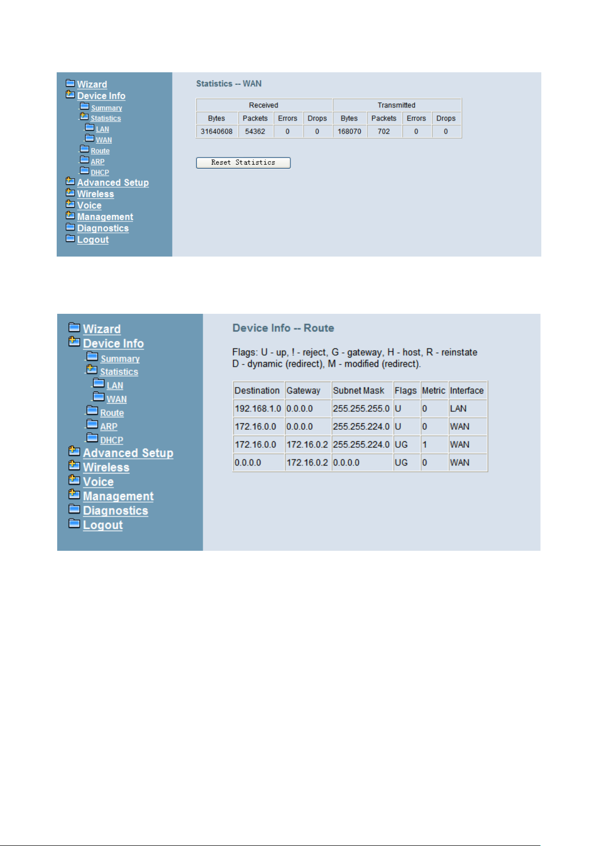
IG7600 Administration Manual
Figure 6-4. Device Info – Statistics – WAN
6.3.3 Route
In this page you can get the IP route information of the device. (Figure 6-5)
Figure 6-5. Device Info – Route
6.3.4 ARP
This page shows an ARP table which maps IP network addresses to hardware
addresses used by data link level protocol. (Figure 6-6)
Copyright 2013 Tecom, Co. LTD. All rights reserved Page 43 of 127
Page 50
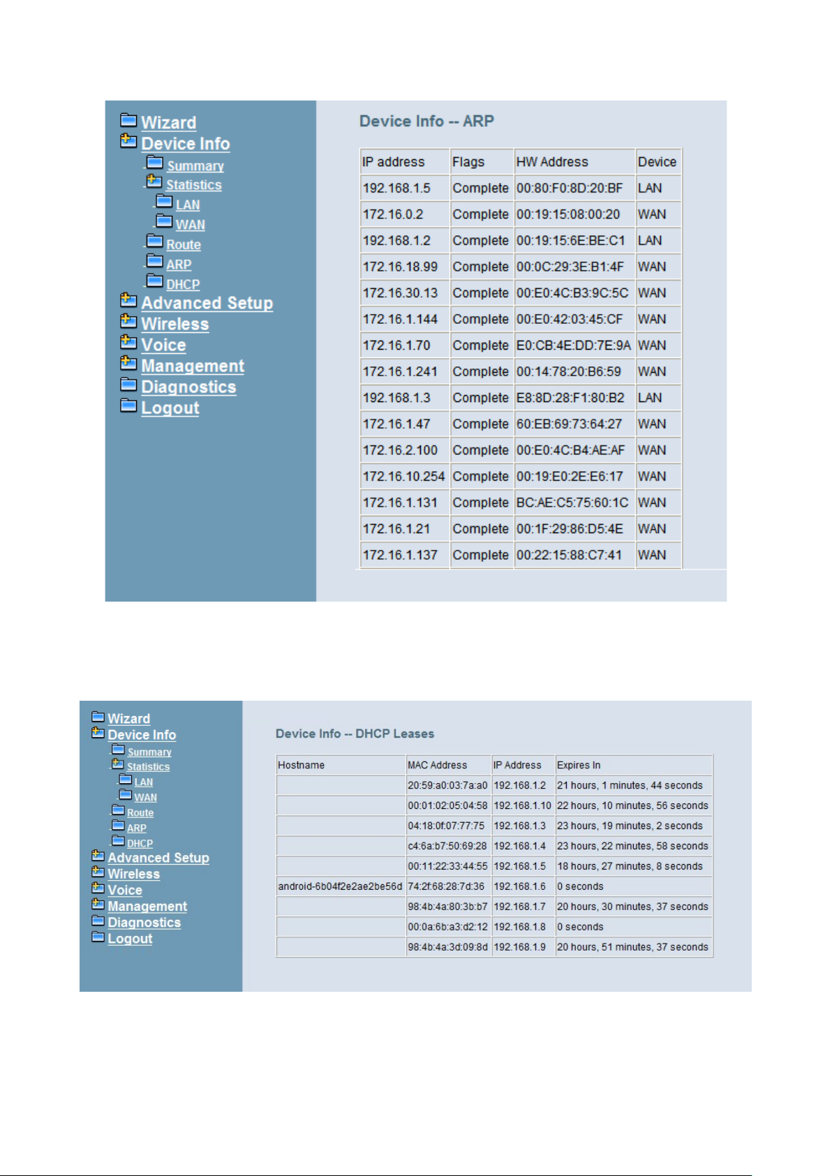
IG7600 Administration Manual
Figure 6-6. Device Info – ARP
6.3.5 DHCP
This page shows a DHCP Leases table which shows the all used IP addresses under
IG7600’s DHCP Server. (Figure 6-7)
Figure 6-7. Device Info – DHCP
Copyright 2013 Tecom, Co. LTD. All rights reserved Page 44 of 127
Page 51
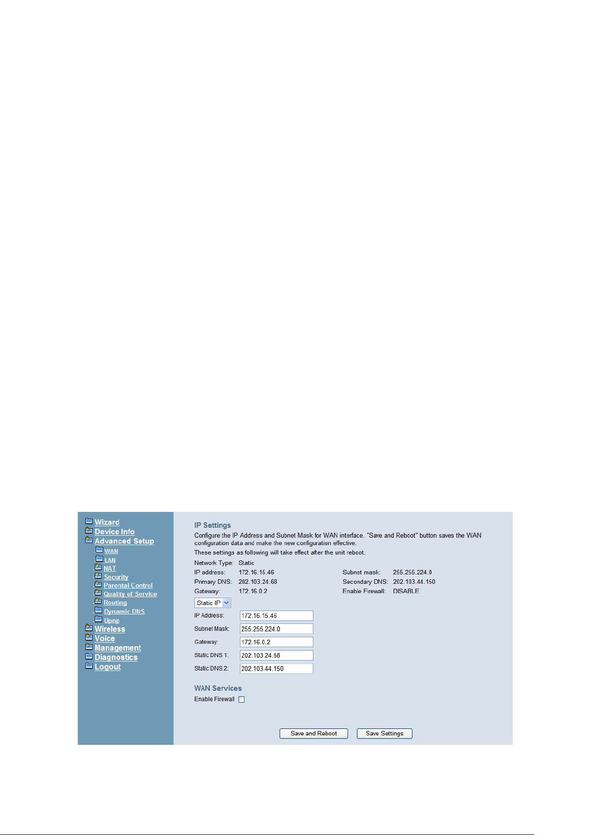
IG7600 Administration Manual
6.4 Advanced Setup
Advanced Setup allows system administrator to configure the following topics:
WAN
LAN
NAT
- Virtual Servers
- Port Triggering
- DMZ Host
Security
- IP Filtering
Outgoing
Incoming
Parental Control
- Time Restriction
- URL Filter
Quality of Service
- DSCP Marking
- Bandwidth Control
Routing
- Static Route
Dynamic DNS
Upnp
6.4.1 WAN
There are three modes that you can give WAN IP address to IG7600: Static IP mode,
DHCP mode and PPPoE mode. You can also enable or disable Firewall.
Network Address Translation (NAT) allows you to share one public WAN IP address for
multiple computers on your LAN side. In IG7600, NAT is enabled by default and i s not
shown on the page to prevent it from being disabled.
This page shows the setting of WAN interface which is Static IP mode (Figure 6-8).
Figure 6-8. Advanced – WAN (Static IP Mode)
Copyright 2013 Tecom, Co. LTD. All rights reserved Page 45 of 127
Page 52
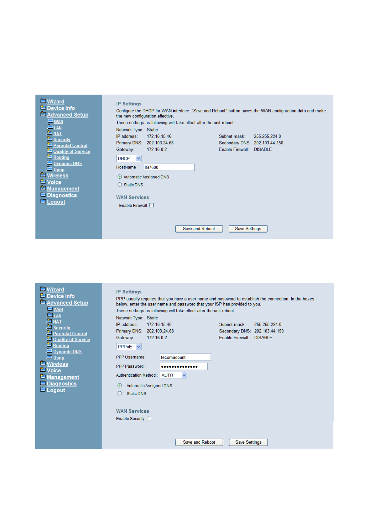
IG7600 Administration Manual
The Dynamic Host Configuration Protocol (DHCP) is an Internet protocol for automating
the configuration of computers that use TCP/IP. DHCP can be used to automatically
assign IP addresses, to deliver TCP/IP stack configuration parameters such as the
subnet mask and default router, and to provide other configuration information.
This page shows the setting of WAN interface which is DHCP m ode (Figure 6-9).
Figure 6-9. Advanced – WAN (DHCP Mode)
The Point -to-Point Protocol over Ethernet (PPPoE) requires a user name and password
that your ISP has provided to you to establish your connection. This page shows the
setting of WAN interface which is PPPoE mode (Figure 6-10).
Figure 6-10. Advanced – WAN (PPPoE Mo de)
Copyright 2013 Tecom, Co. LTD. All rights reserved Page 46 of 127
Page 53
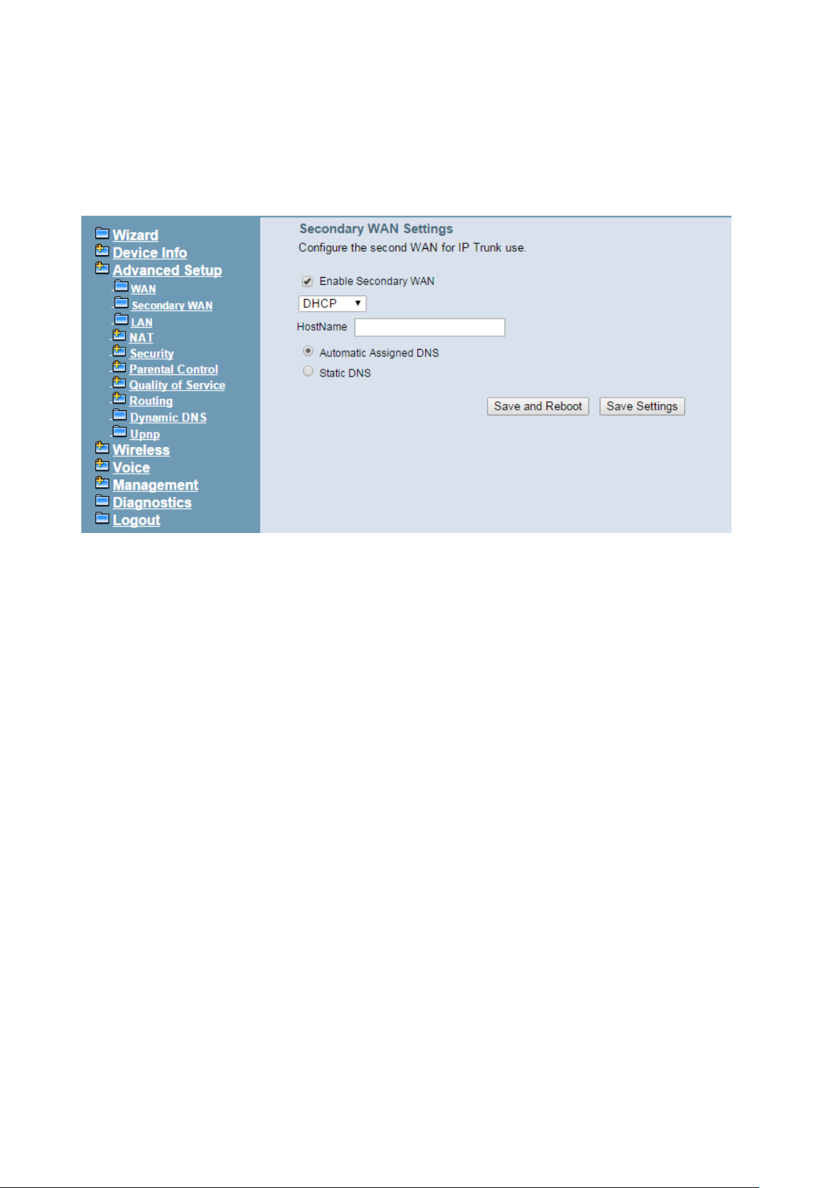
IG7600 Administration Manual
6.4.2 Secondary WAN
IG7600 supports secondary WAN which is dedicated for IP Trunk. If you check “Enable
Secondary WAN” then it will turn LAN por t i n t o sec on dar y WAN port. And you still can use
wireless interface for LAN access. Regarding secondary WAN settings, please refer to
6.4.1 WAN settings.
6.4.3 LAN
It allows you to s e t LAN IP and Subn et M as k for LAN interfac e. A DSP IP address ca n be
configured for FXO/FXS application. You can also enable or disable DHCP Server and
configure rel ated s etti ngs. End IP Camera Address cannot be configured; it is generated
automatically when you config ure the Star t IP Camera Addr ess. The “Static IP Lease List”
allows to program 32 entries to have the fixed IP address for the specified devices. If
needed, it can also configure the second IP address and Subnet Mask for the LAN
interface (Figure 6-11).
Info: If the DHCP Pool is changed, and the new “Start IP Address” is bigger than
the older one or the new “End IP Address” is sm aller than the older one, the Static
IP Lease List will be cleared automatically.
Copyright 2013 Tecom, Co. LTD. All rights reserved Page 47 of 127
Page 54
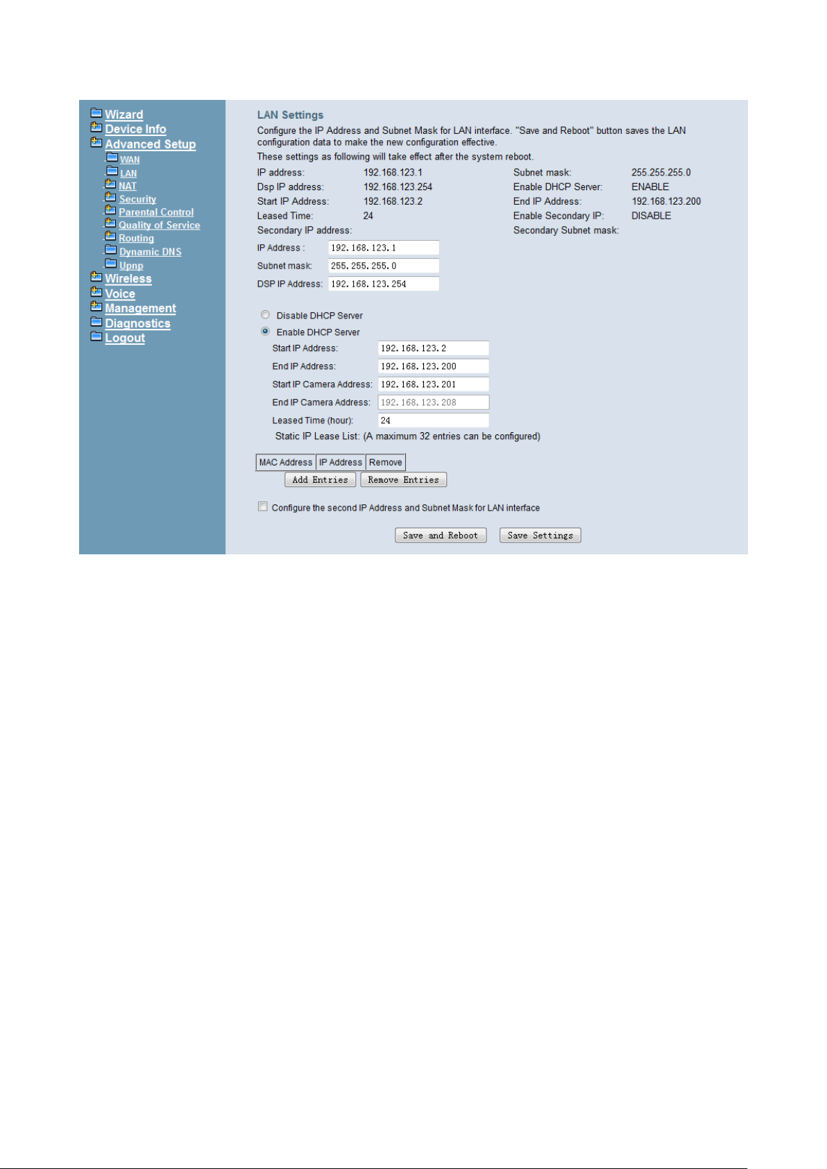
IG7600 Administration Manual
Figure 6-11. Advanced – LAN
6.4.4 NAT
It’s separated into three parts: Virtual Servers, Port Triggering, and DMZ Host.
6.4.4.1 Virtual Servers
Virtual Server allows you to direct incoming traffic from WAN side identified by Protocol
and External port to the internal server with private IP address on the LAN side. The
“Internal Port” can be modified if the “External Port” needs to be converted to a different
port number use d by th e ser ver on th e L AN si de. The r emote IP sho uld be speci fied in the
table to allow the access. A maximum 32 entries can be configured. (Figure 6-12, Figure
6-13)
Copyright 2013 Tecom, Co. LTD. All rights reserved Page 48 of 127
Page 55
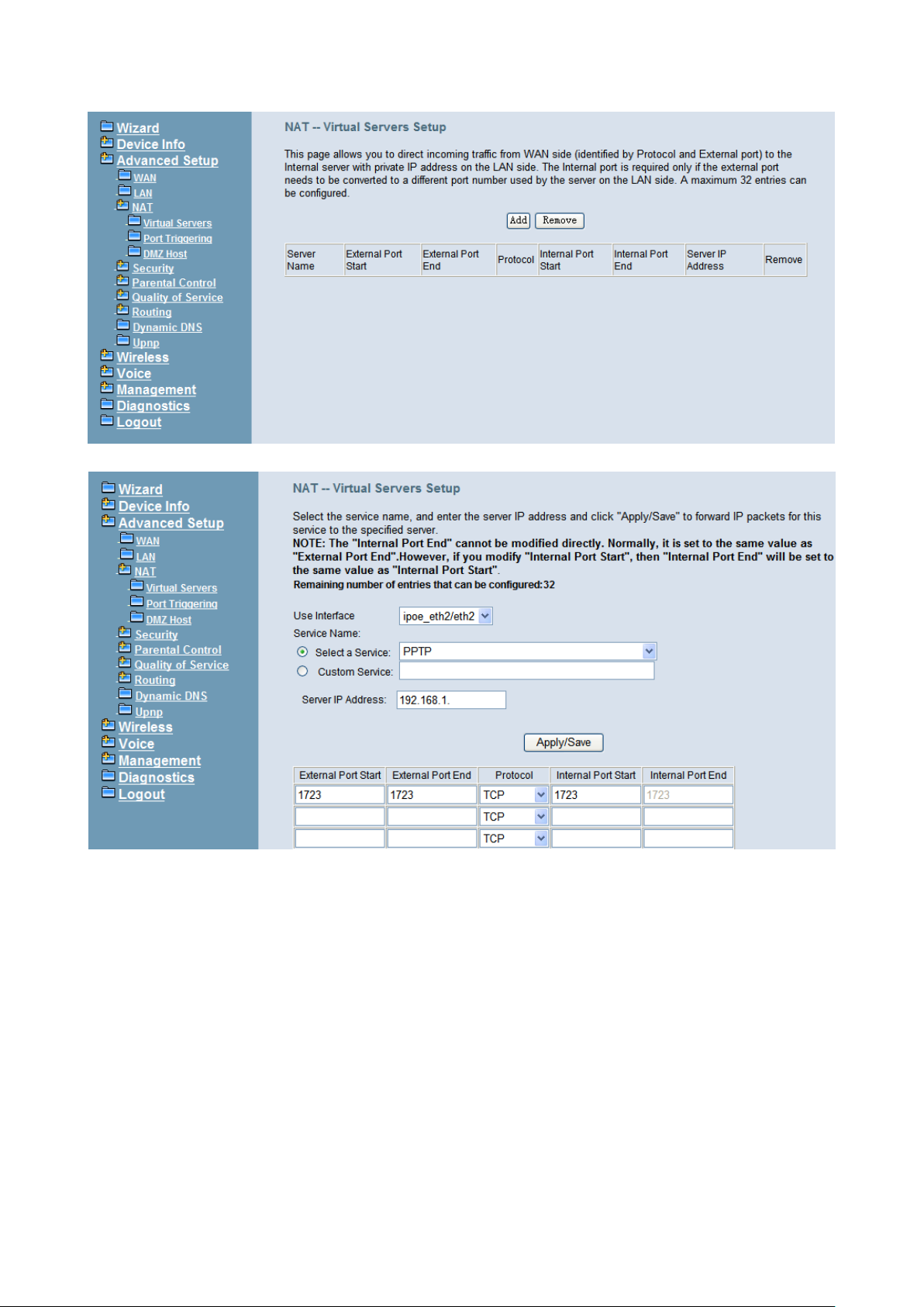
IG7600 Administration Manual
Figure 6-12. Advanced – NAT – Virtual Servers
Figure 6-13. Advanced – NAT – Virtual Servers – Add
6.4.4.2 Port Triggering
Some applications require that specific ports in the IG7600's firewall opened for acc es s
by the remote parties. Port Triggering dynamically opens up the "Open Ports" in the
firewall when an application on the LAN initiates a TCP/UDP connection to a remote
party using the "Trigger Ports". IG7600 allows the remote party from the WAN side to
establish new connections back to the application on the LAN side using the "Open
Ports". A maximum 32 entries can be configured. (Figure 6-14,Figure 6-15)
Copyright 2013 Tecom, Co. LTD. All rights reserved Page 49 of 127
Page 56
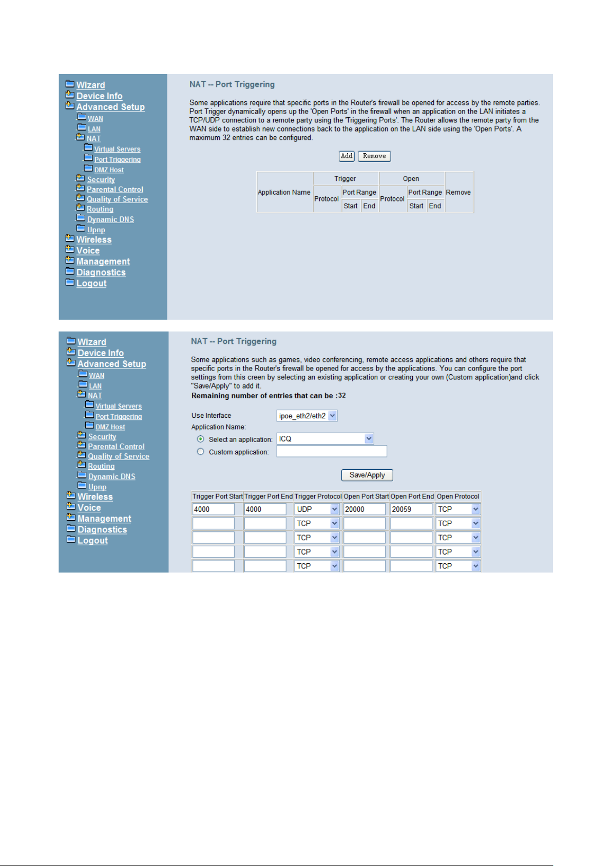
IG7600 Administration Manual
6.4.4.3 DMZ Host
Figure 6-14. Advanced – NAT – Port Triggering
Figure 6-15. Advanced – NAT – Port Triggering – Add
IG7600 will forward IP packets that do not belong to any of the applications configured in
the Virtual Serv ers table to the DMZ host com put er. Enter the computer's IP ad dr es s a nd
click "Save Settings" to activate the DMZ host. Clear the IP address field and click "Save
Settings" to deactivate the DMZ host. (Fi g ur e 6-16)
Copyright 2013 Tecom, Co. LTD. All rights reserved Page 50 of 127
Page 57
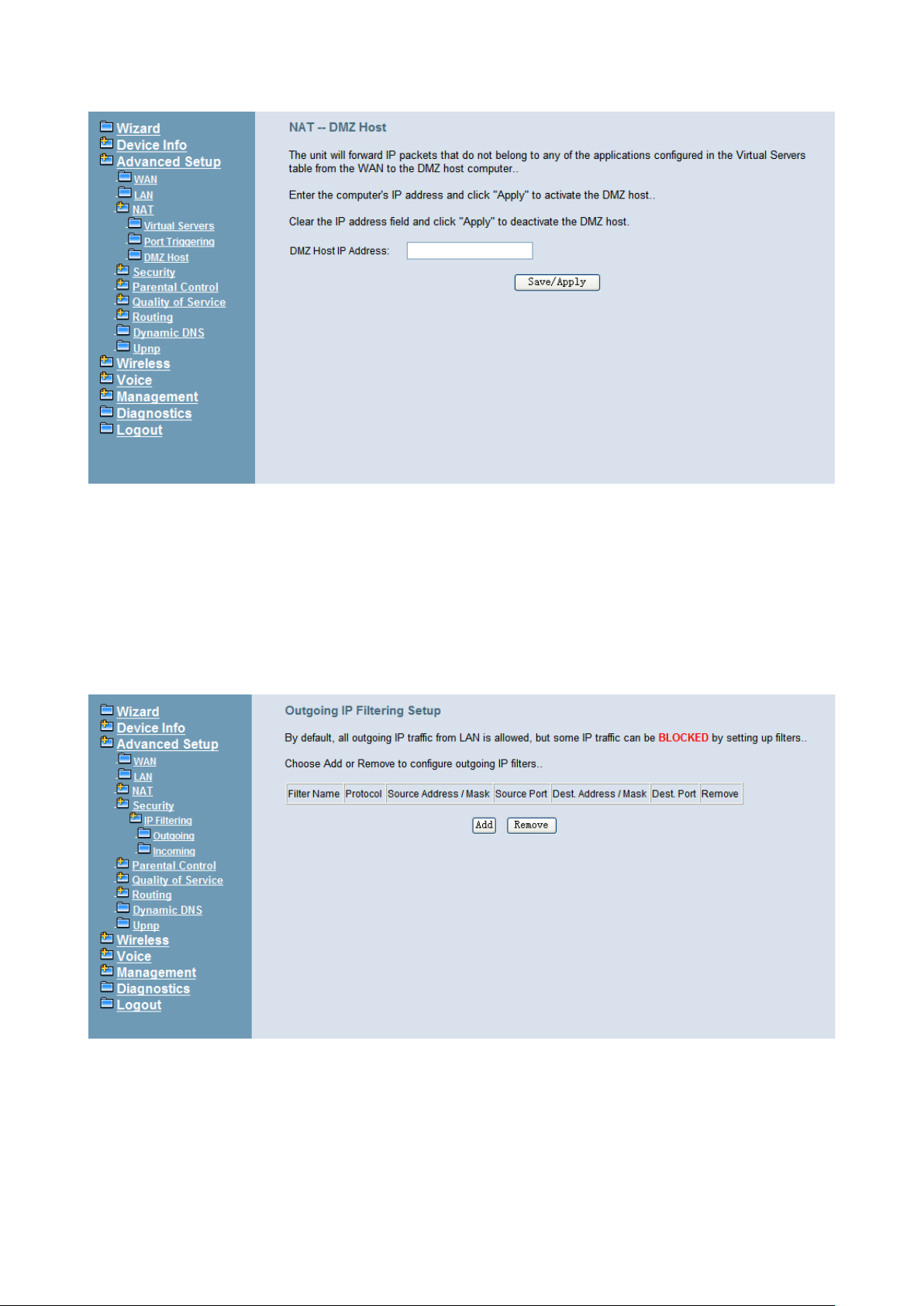
IG7600 Administration Manual
Figure 6-16. Advanced – NAT – DMZ
6.4.5 Security
It supports IP Filtering Setup. It’s separated into two parts: Outgoing and Incoming.
6.4.5.1 IP Filtering - Outgoing
It allows the administrator to create a filter rule to identify outgoing IP traffic by specifying
a new filter name. At least one condition is needed. All of the specified conditions in this
filter rule must be satisfied for the rule to take effect. (Figure 6-17,Figure 6-18)
Figure 6-17. Advanced – Security – IP Filtering – Outgoing
Copyright 2013 Tecom, Co. LTD. All rights reserved Page 51 of 127
Page 58
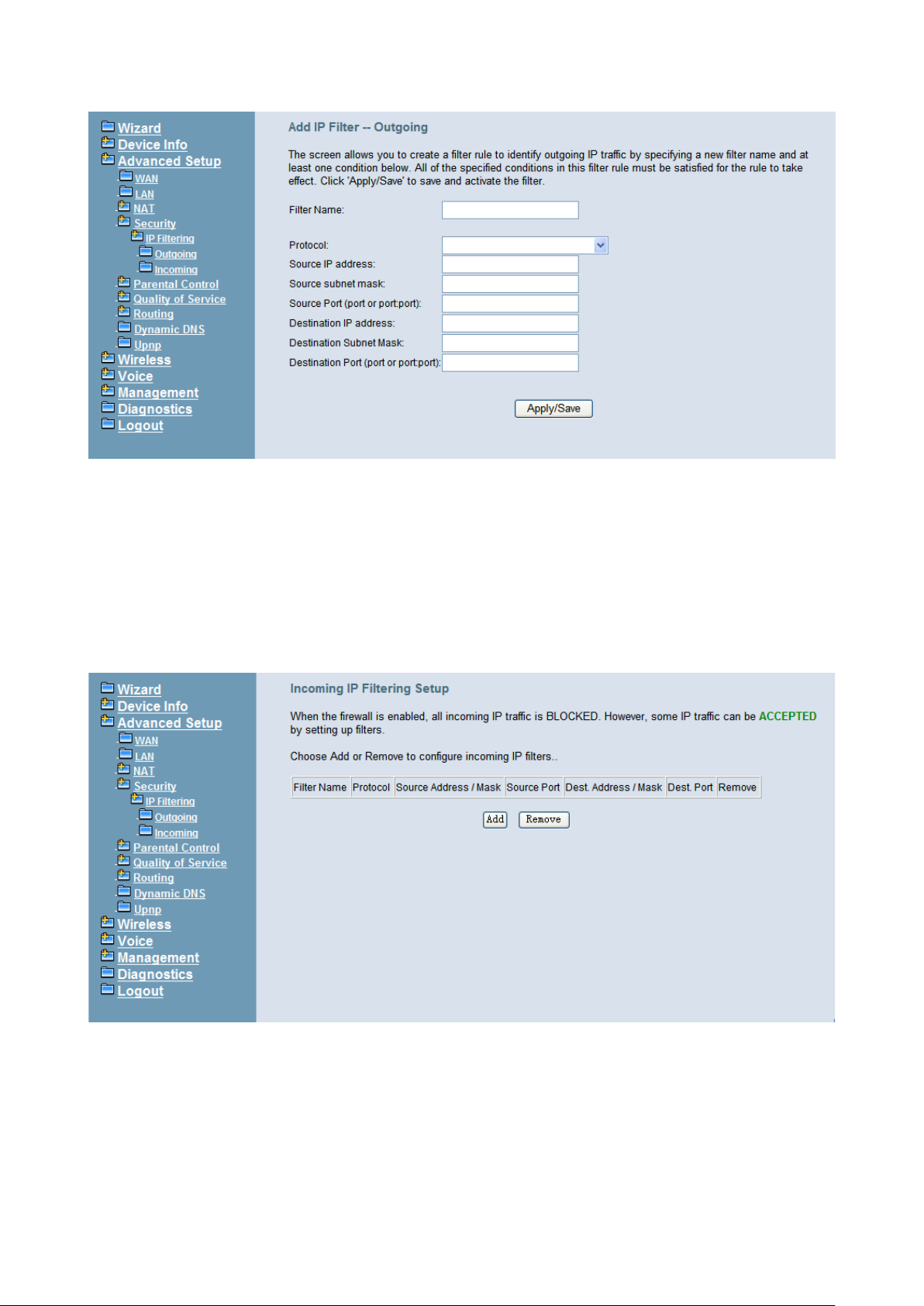
IG7600 Administration Manual
Figure 6-18. Advanced – Security – IP Filtering – Outgoing – Add
6.4.5.2 IP Filtering - Incoming
It allows the administrator to creat e a fil ter r ule to identify inco mi ng IP tr affic by specifying
a new filter name. At least one condition is needed. All of the specified conditions in this
filter rule must be satisfied for the rule to take effect. (Figure 6-19, Figure 6-20)
By default, all incoming IP traffic from the WAN will be blocked if it is not consistent with
the incoming filter rules. In fact, IG7600 has opened some necessary ports such as web
port, sip port, and rtp port, to make sure that voice application can communicate well.
Figure 6-19. Advanced – Security – IP Filtering – Incoming
Copyright 2013 Tecom, Co. LTD. All rights reserved Page 52 of 127
Page 59
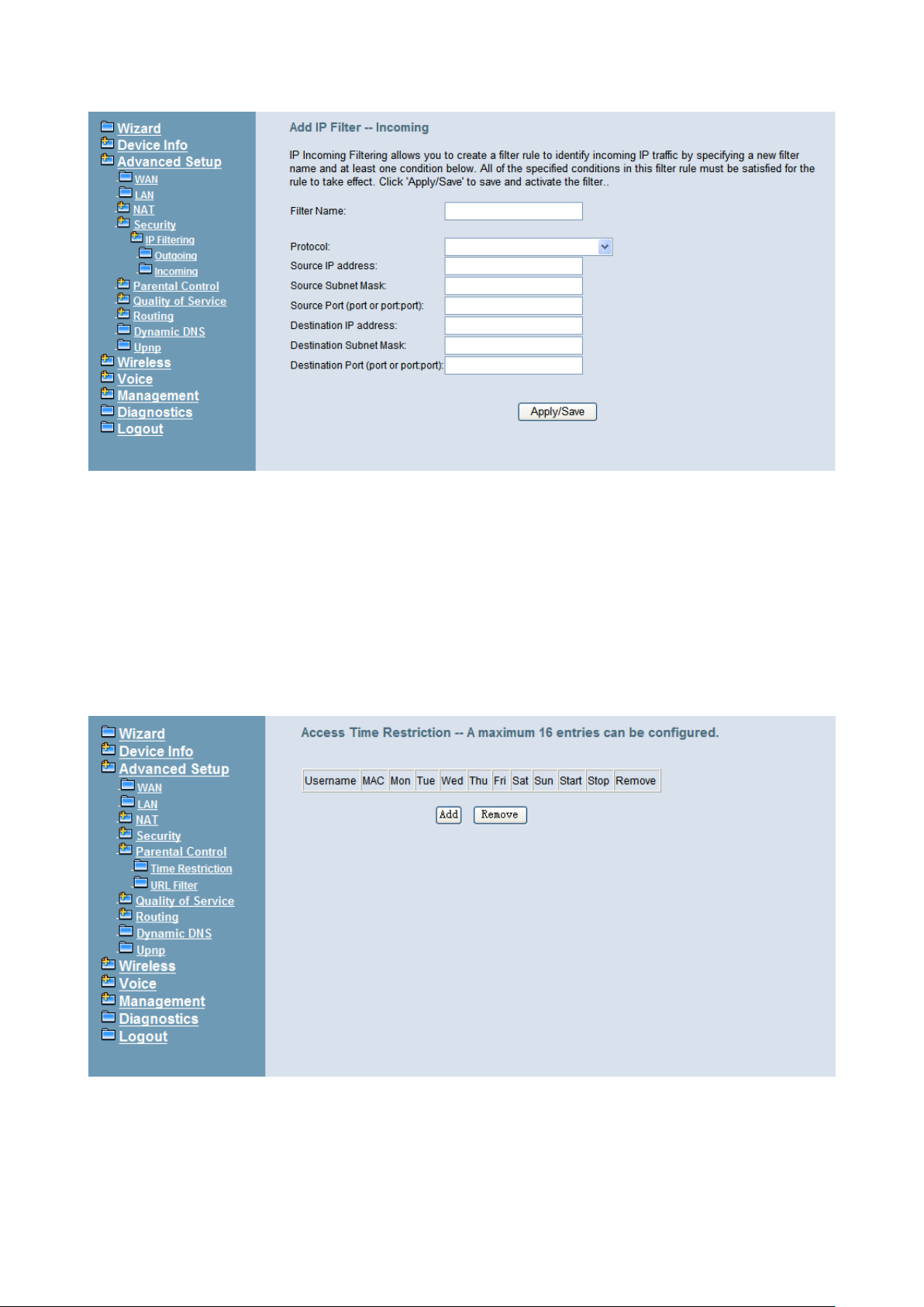
IG7600 Administration Manual
Figure 6-20. Advanced – Security – IP Filtering – Incoming – Add
6.4.6 Parental Control
It’s separated into two parts: Time Restriction, and URL Filter.
6.4.6.1 Time Restriction
The administrator can add time restriction to a special LAN device connected to IG7600.
The “Browser's MAC Address” automatically displays the MAC address of the LAN
device where the browser is running. To restrict other LAN device, click the "Other MAC
Address" button and enter the MAC address of the other LAN device. (Figure 6-21,
Figure 6-22)
Figure 6-21. Advanced – Parental Control – Time Restriction
Copyright 2013 Tecom, Co. LTD. All rights reserved Page 53 of 127
Page 60
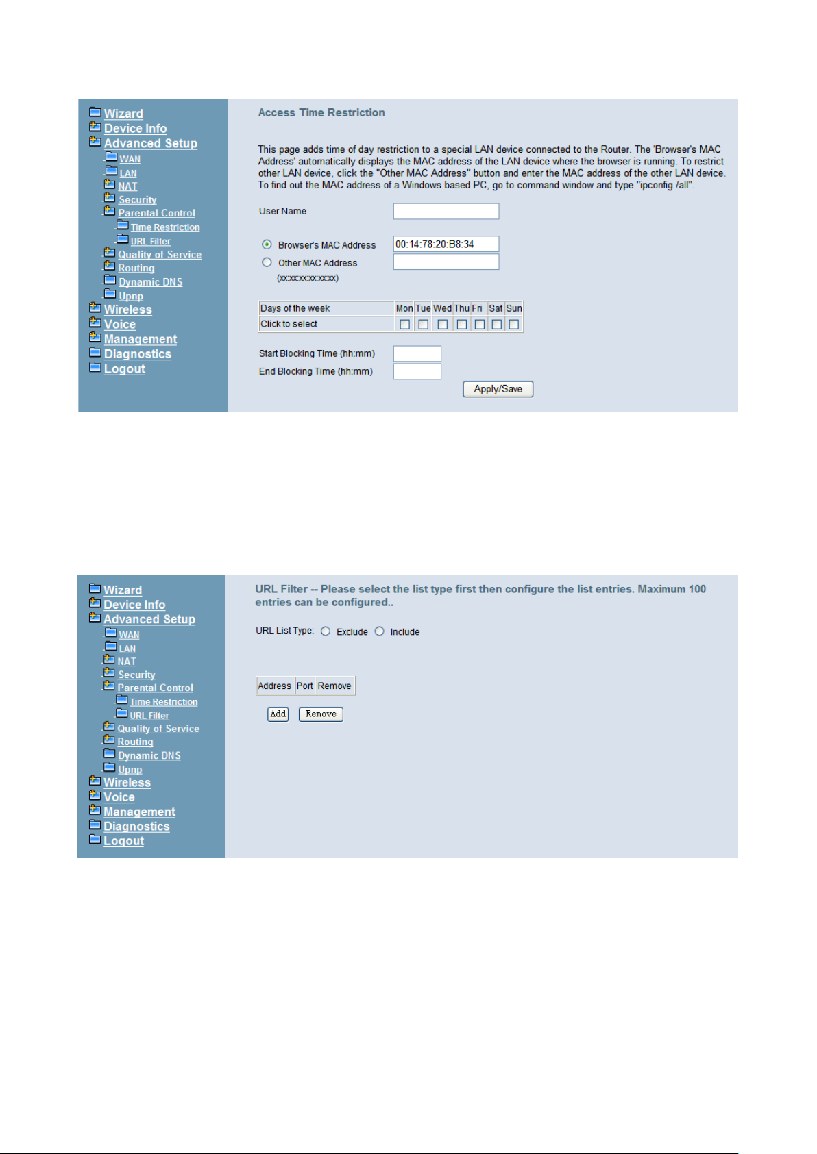
IG7600 Administration Manual
Figure 6-22. Advanced – Parental Control – Time Restriction – Add
6.4.6.1 URL Filter
The administrator can add 100 e ntri es max imum to incl ude/ ex clude t he UR L addres s a n d
Port number. Choos e “Incl ude” means the user c an only conn ect to the U RL that y ou add.
Choose “Exclude” mea ns th e user cannot connect to t he UR L tha t y ou add. “ Incl ude” and
“Exclude” are exclusive. The all entries are for the selected type. (Figure 6-23, Figure
6-24).
Figure 6-23. Advanced – Parental Control – URL Filter
Copyright 2013 Tecom, Co. LTD. All rights reserved Page 54 of 127
Page 61
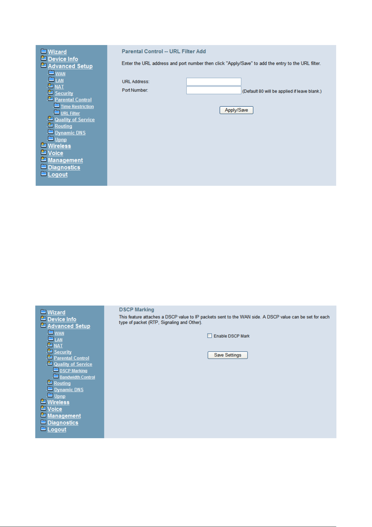
IG7600 Administration Manual
Figure 6-24. Advanced – Parental Control – URL Filter – Add
6.4.7 Quality of Service
It’s separated into two parts: DSCP Marking, and Bandwidth Control
6.4.7.1 DSCP Marking
IP QoS is applied to the traffic from LAN to WAN; the traffic from WAN to LAN will not be
applied. (Figure 6-25)
If "Enable DSCP Mark” checkbox is selected, choose a default DSCP mark to
automatically mark inc oming tr af fic w ithout re ference t o a parti cular class ifier. Cl ick " Sav e
Settings" button t o save it. N ote: If "En able DSCP Mar k” checkbox is not selec ted, all Qo S
will be disabled for all interfaces. The default DSCP mark is used to mark all egress
packets.
Figure 6-25. Advanced – Quality of Service – DSCP Marking
6.4.7.2 Bandwidth Control
Bandwidth Control allows you to control WAN port's upstream bandwidth according to
your settings, and it can ensur e the highest pr iority IP packet traffic t hroughput. By default,
Copyright 2013 Tecom, Co. LTD. All rights reserved Page 55 of 127
Page 62
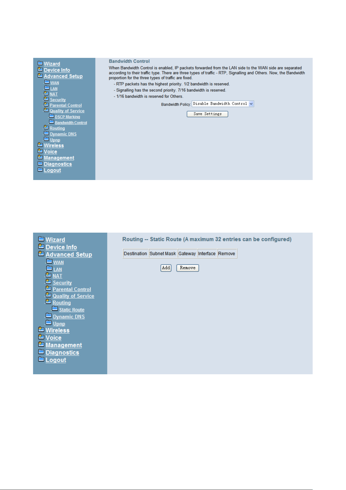
IG7600 Administration Manual
all voice packets have been queued in the highest IP packets, and the others have been
queued in the normal IP packets if they have not been set in the traffic class rule.
Figure 6-26. Advanced – Quality of Service – Ba ndw idt h Control
6.4.8 Routing
6.4.8.1 Static Route
The Static Route allows you to add special routing rules into routing table.
Figure 6-27. Advanced – Route – Sta ti c Route
Click “Add” to create a new Static Route. Enter the destination network address, subnet
mask, gateway AND/OR available WAN interface then click "Save Settings" to add the
entry to the routing table. (Figure 6-27, Figure 6-28)
Copyright 2013 Tecom, Co. LTD. All rights reserved Page 56 of 127
Page 63
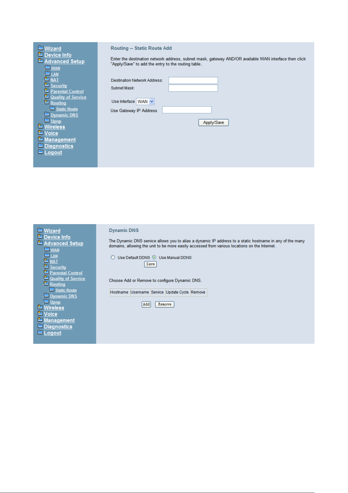
IG7600 Administration Manual
Figure 6-28. Advanced – Route – Sta ti c Route – Add
6.4.9 Dynamic DNS
The Dynamic DNS service allows you to alias a register domain name to a dynamic IP
address. It allows IG7600 to be more easily accessed from various locations on the
Internet. Click “Add” or “Remove” to configure Dynamic DNS. (Figure 6-29)
Figure 6-29. Advanced – Dynamic DNS
Now IG7600 support for three DDNS provider, DynDNS.org and TZO and custom
provider. Specify the register hostname and choose the related interface. Fill in the
username/password or email/key and click “Apply/Save”. IG7600 will update the current
IP with DDNS prov ider w hen click “Apply /Save” or sy stem reboot s uccessfully . IG7600 will
also update the current IP automatically with DDNS provider in the programmed Update
Cycle. (Figure 6-30, Figure 6-31, Figure 6-32)
Copyright 2013 Tecom, Co. LTD. All rights reserved Page 57 of 127
Page 64
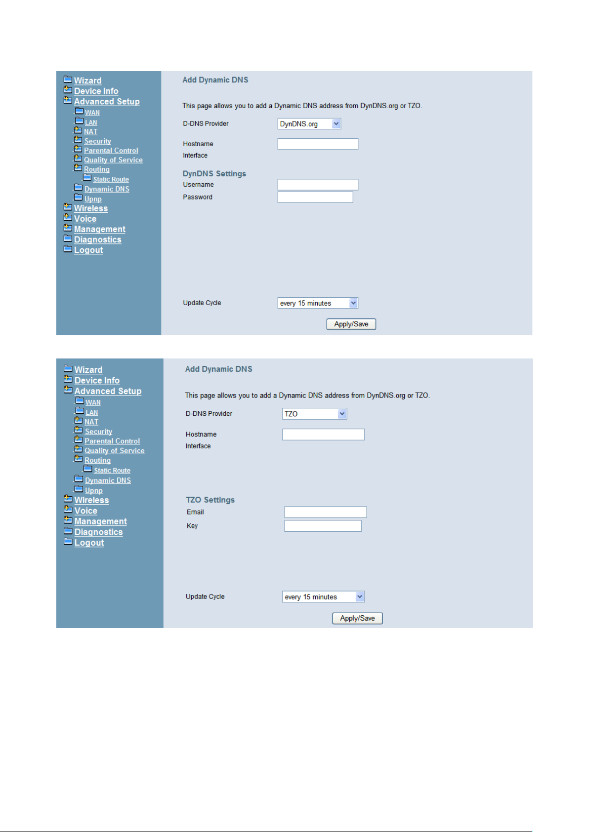
IG7600 Administration Manual
Figure 6-30. Advanced – Dynamic DNS – DynDNS.org
Figure 6-31. Advanced – Dynamic DNS – TZO
Copyright 2013 Tecom, Co. LTD. All rights reserved Page 58 of 127
Page 65
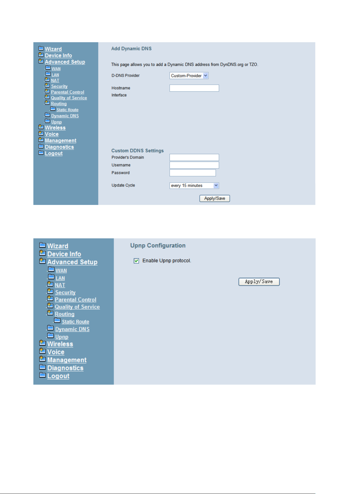
IG7600 Administration Manual
Figure 6-32. Advanced – Dynamic DNS – Customer-Provider
6.4.10 Upnp
It’s used to enable or disable the universal plug and play function. (Figure 6-33)
Figure 6-33. Advanced – Upnp
6.5 Wireless
Use the Wireless screen to configure the IG7600 for wireless access. It is separated into
7 parts:
Basic
- Primary
- Additional
Copyright 2013 Tecom, Co. LTD. All rights reserved Page 59 of 127
Page 66
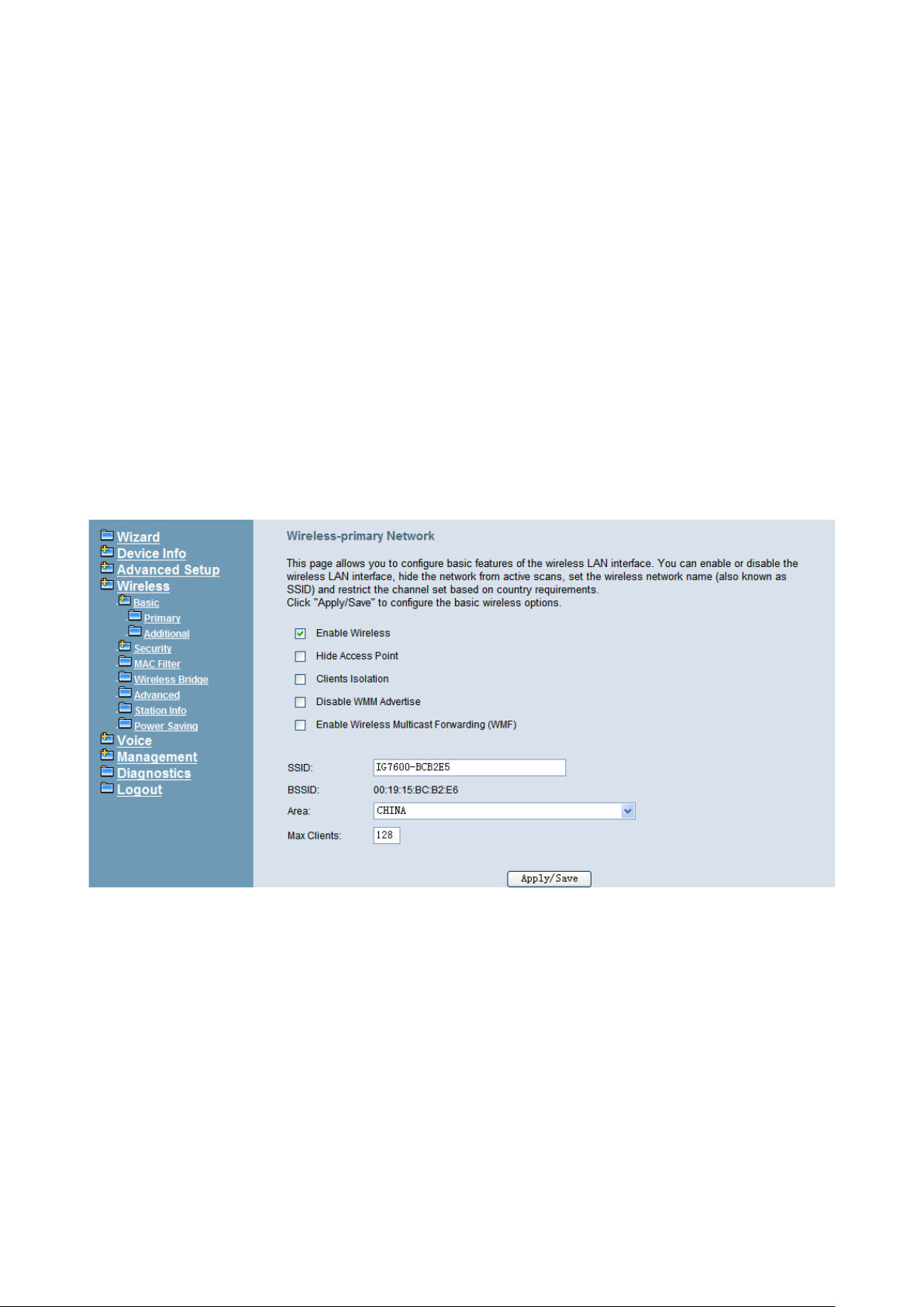
IG7600 Administration Manual
Security
MAC Filter
Wireless Bridge
Advanced
Station Info
Power Saving
The configurable items for each part would be described in the following.
6.5.1 Basic
It’s separated into two parts: Primary, and Additional.
6.5.1.1 Primary
This page allows you to configure the basic features of the wireless LAN interface. You
can enable or disable the wireless LAN interface, hide the network from active scans,
active the client isolation, disable WMM advertise and enable wireless multicast
forwarding.
User can set the wireless network name (also known as SSID) and restrict the channel
set based on country requirements. Th e max cli ents are 16. (Figure 6-34)
Figure 6-34. Wireless – Basic – Primary
6.5.1.2 Additional
IG7600 supports to configure 3 additional Wireless networks. Each SSID can have
different name and configurations. (Figure 6-35)
Copyright 2013 Tecom, Co. LTD. All rights reserved Page 60 of 127
Page 67
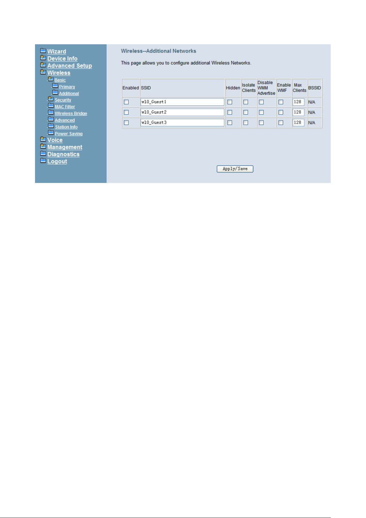
IG7600 Administration Manual
Figure 6-35. Wireless – Basic – Additional
Copyright 2013 Tecom, Co. LTD. All rights reserved Page 61 of 127
Page 68
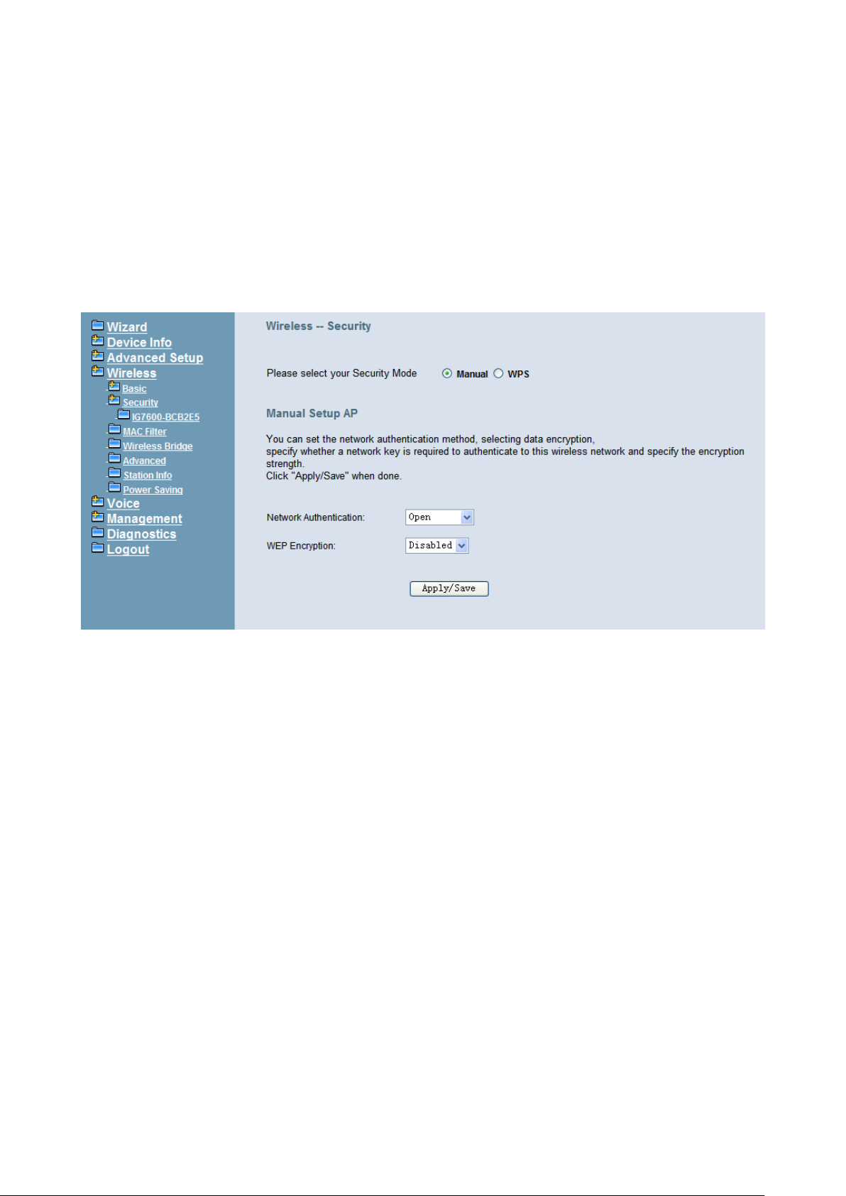
IG7600 Administration Manual
6.5.2 Security
This page allows you to configure security features of the wireless LAN interface. It
allows you to select your Security Mode: Manual and WPS.
In WPS mode, it follow s t he Wi-Fi Prot ecte d Setup s tan dard for easy and sec ur e wi rel ess
network set up and connection. User can use Push-Button or PIN to configure the
connection with IG7600. In Push-Button m et h od, IG 76 00 and cli ent must pr es s t he WPS
button to establ ish connecti on. In PIN mode, w hen the Access Point Pin is used, clie nt can
input the PIN to establish the connection. When the External Device PIN is used, client
device PIN can be entered in the field to establish connection (Figure 6-36).
Figure 6-36. Wireless – Security
In Manual mode, you can set the network authentication method, selecting data
encryption, specify whether a network key is required to authenticate to this wireless
network and specify the encryption strength. Click "Apply/Save" to configure the wireless
security options. (Figure 6-37, Figure 6-38)
The following items will be configured in the page:
Network Authentication: Set the network Authentication method. Open and Shared
can use the WEP Encryption. 802.1X and WPA require setting valid RADIUS
parameters. WPA-PSK requires a valid WPA Pre-Shared Key to be set.
802.1X: As the IEEE standard for access control for wireless and wired LANs, 802.1x
provides a means of authentication and authorizing devices to attach to a LAN port.
This standard defines the Extensible Authentication Protocol (EAP), which uses a
central authentication server to authenticate each user on t he network.
WPA/WPA2: The Wi-Fi Alliance put together WPA/WPA2 as a data encryption
method for 802.11 wireless LANs. WPA is an industry-supported, pre-standard
version of 802.11i utilizing the Temporal Key Integrity Protocol (TKIP), which fixes the
problems of WEP, including using dynamic keys.
WPA/WPA2 Pre-Shared Key: Set the WPA/WPA2 Pre-Shared Key (PSK).
WPA/WPA2 Group Rekey Interval: Set the WPA/WPA2 Group Rekey Interval in
seconds. Leave blank or set to zero to disable periodic re-keying.
Copyright 2013 Tecom, Co. LTD. All rights reserved Page 62 of 127
Page 69
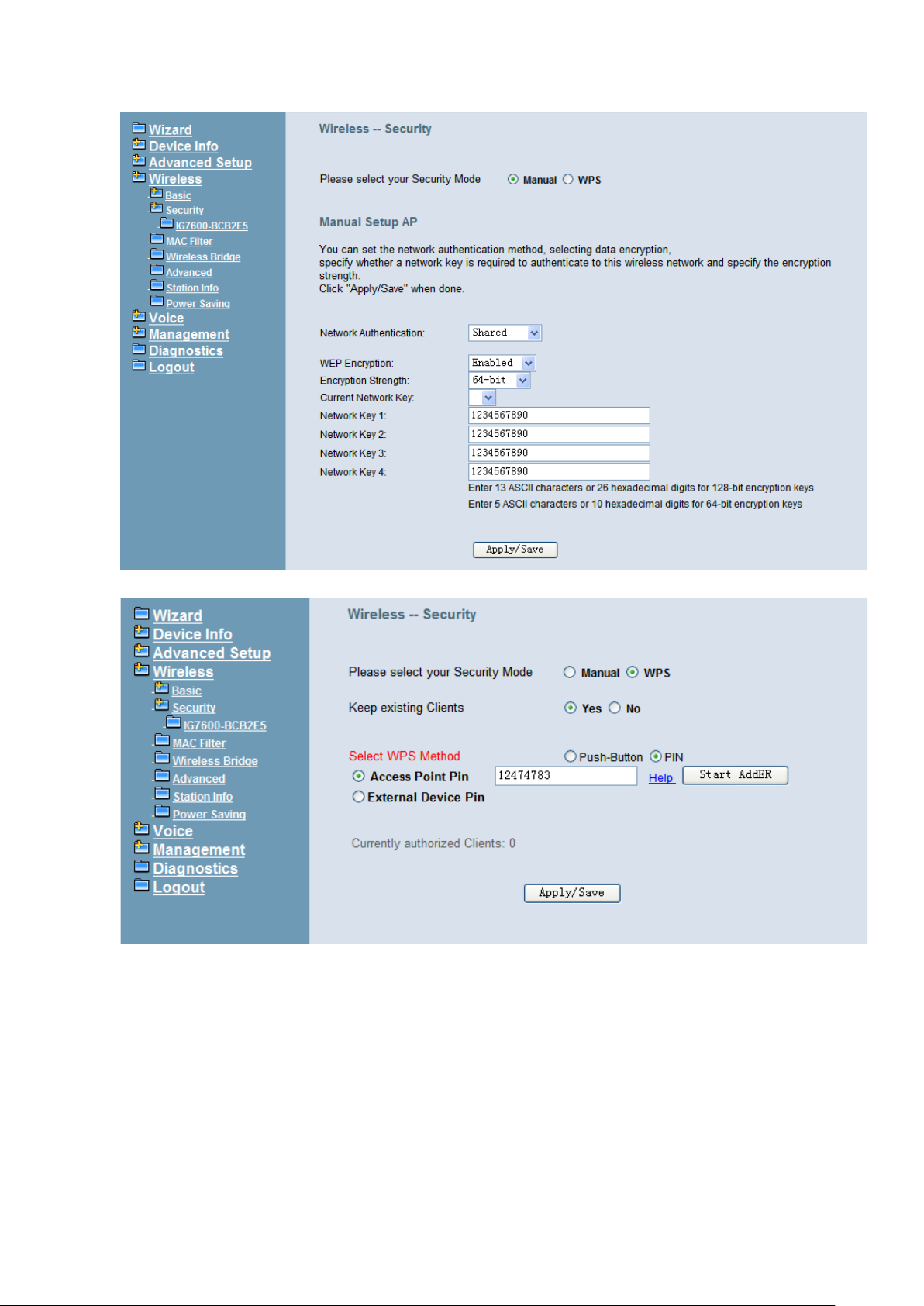
IG7600 Administration Manual
Figure 6-37. Wireless – Security – 1
Figure 6-38. Wireless – Security – 2
WEP Encryption: Selecting Disabled disables WEP data encryption. Selecting
Enabled enables WEP data encryption and requires that a valid network key be set
and selected unless 802.1X is enabled.
WEP, short for Wired Equivalent Privacy, is a protocol for wireless LANs or local area
networks. This WEP is defined in the 802.11 Standard. WEP is designed so security
levels are maintained at the same level as the wired LAN. WEP’s aim is to provide
security by encrypting data over radio waves. WEP protects data as it’s transmitted
from one end point to another. WEP is used at two lowest layers, the data link and
Copyright 2013 Tecom, Co. LTD. All rights reserved Page 63 of 127
Page 70
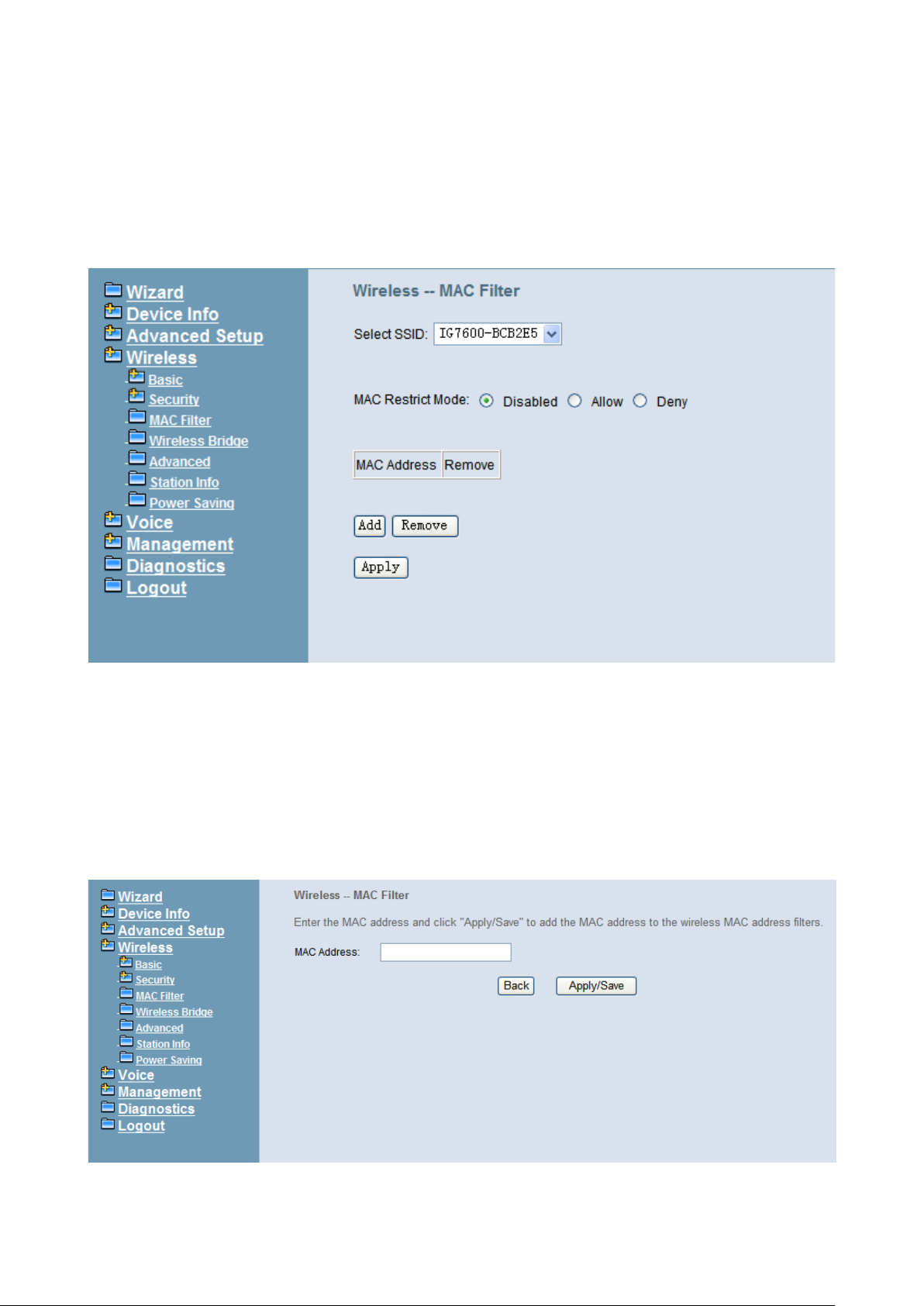
IG7600 Administration Manual
physical layer. WEP is designed to make up for the inherent security in wireless
transmission as compared to wired transmission.
Network Key: Set whether shared key authentication is required to associate. A valid
network key must be set and selected if required.
6.5.3 MAC Filter
Figure 6-39. Wireless – MAC Filter
This page allows users to Add/Remove hosts with the specified MAC addresses that are
able or unable to access the wireless network. When users decide to use Allow, only the
MAC addressed in the user-defined list can access the wireless network. When users
use Deny, only the user specified MAC addresses are unable to access to wireless
network. And if the Disable option is selected, all users will be able to access to wireless
network.
Note: The MAC addres ses i n th e li st w oul d immedi atel y tak e e ffec t w hen Al low or D eny is
checked. (Figure 6-39, Figure 6-40)
Figure 6-40. Wireless – MAC Filter – Allow/Deny
Copyright 2013 Tecom, Co. LTD. All rights reserved Page 64 of 127
Page 71

IG7600 Administration Manual
6.5.4 Wireless Bridge
This page allows you to configure wireless bridge features of the wireless LAN interface.
You can select Wireless Bridge (also known as Wireless Distribution System) to connect
to other wireless bridge device, but the access point funct ionality will be disabled.
Selecting Access Point enables access point functionality. Wireless bridge functionality
will still be available and wireless stations will be able to associate to the AP. Select
Disabled in Bridge R est rict whi ch dis ables w ireless br idg e restr icti on. A ny w irel ess br idge
will be granted access. Selecting Enabled or Enabled (Scan) enables wireless bridge
restriction. Only those bridges selected in Remote Bridges will be granted access. Click
"Refresh" to update the remote bridges. Wait for few seconds to update. Click "Save
Settings" to configure the wireless bridge options. (Figure 6-41)
Figure 6-41.
Wireless – Wireless Bridge
6.5.5 Advanced
It allows you to configure advanced features of the wireless LAN interface. You can
select a particular channel on which to operate, force the t r a nsmi ss ion rate to a parti cul ar
speed, set the frag mentation thresh old, set th e RTS thr eshold, s et the w akeup inter val fo r
clients in power-save mode, set the beacon interval for the access point, set XPress
mode and set whether short or long preambles are used. Click "Save Settings" to
configure the advanced wireless options. (Figure 6-42)
Band: Default setting is 2.4GHz.
Channel: Select the appropriate channel from the list provided to correspond with
your network set tings. All dev ices i n your wi reless netw ork must use the same ch annel
in order to function correctly.
Auto Channel Timer: The IG7600 should search for the best wireless channel in this
period (minute).
802.11n/EWC: Automatic or disable 802.11n support.
Bandwidth: User can choose 20MHz/40MHz in both band or 20MHz in 2.4G
band/40MHz in 5G band.
Copyright 2013 Tecom, Co. LTD. All rights reserved Page 65 of 127
Page 72

IG7600 Administration Manual
Control Sideband: Specify if the extension channel should be in the “Upper” or
“Lower” sideband.
802.11n Rate: Set the Physical Layer rate. These rates are only applicable when
the”802.11n/EWC” is confi g ur ed as “Auto”.
802.11n Protection: In “Auto” mode, the wireless devices use RTS/CTS to improve
802.11n performance in mixed 802.11g/802.11b networks. Turn protection off to
maximize 802.11n throughput under most conditions. Do not disable 802.11n
protection if there is a possibil ity that 802. 11b or 802.11g devices wi ll use your wi reless
network.
Support 802.11n Client Only: “On” enables support for 802.11n clients only. Off will
enable support for clients that are not 802.11n.
54g® Rate: The default setting is Auto. The range is from 1 to 54Mbps. The rate of
data transmission should be set depending on the speed of your wireless network.
You can select fro m on e trans miss ion s peed, or k eep th e de fault s etti ng, Aut o, to hav e
the IAD automatically use the fastest possible data rate.
Multicast Rate: The default setting is 54Mbps. The range is from 1 to 54Mbps. The
rate of data transmission should be set depending on the speed of your wireless
network. You can select from one transmission speed, or keep the default setting, to
have the IAD automatically use the fastest data rate for multicast packets.
Basic Rate: Select the basic rate that wireless clients must support.
Fragmentation Threshold: This value should remain at its default setting of 2346.
The range is 256~2346 bytes. It specifies the maximum size for a packet before data
is fragmented into multiple packets. If you experience a high packet error rate, you
may slightly increase the Fragmentation Threshold. Setting this value too low may
result in poor network performance. Only minor modifications of this value are
recommended.
Copyright 2013 Tecom, Co. LTD. All rights reserved Page 66 of 127
Page 73
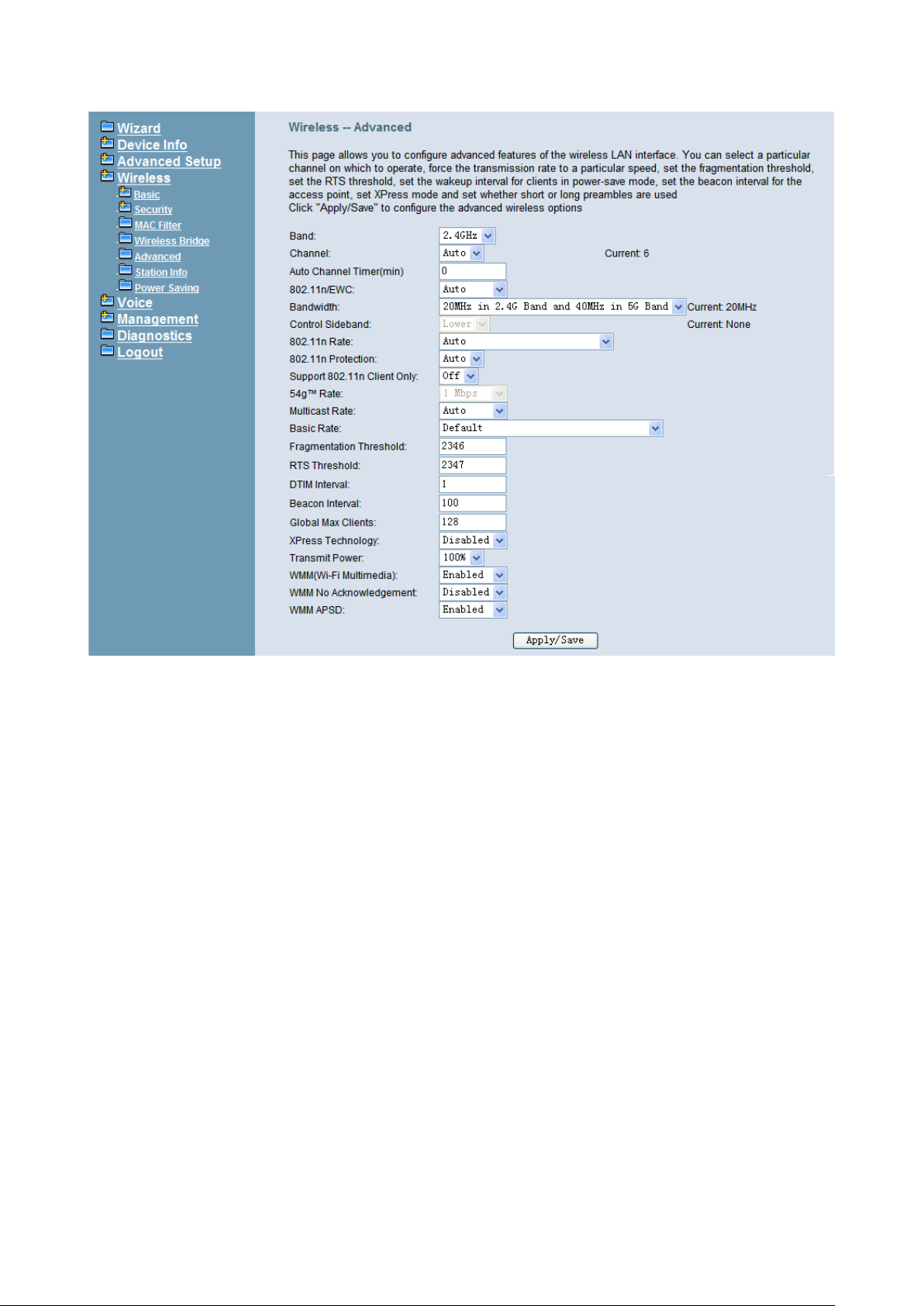
IG7600 Administration Manual
Figure 6-42. Wireless – Advanced
RTS Threshold: This value should remain at its default setting of 2347. The range is
0~2347 bytes. Should you encounter inconsistent data flow, only minor modifications
are recommended. If a network packet is smaller than the packet RTS threshold size,
the RTS/CTS mechanism will not be enabled. The IAD sends Request of Send (RTS)
frames to a particular receiving station and negotiates the sending of a data frame.
After receiving an RTS, the wireless station responds with a Clear to Send (CTS)
frame to acknowledge the right to begin transmission.
DTIM Interval: The default value is 3. This value, between 1 and 255 milliseconds,
indicates the int erv al of t he Del iv ery Traffic I nd icati on Mess ag e (DTI M). A DTIM fiel d is
a countdown field informing clients of the next window for listening to broadcast and
multicast messages. When the router has buffered broadcast or multicast for
associated clients, it sends the next DTIM with a DTIM Interval value. Its clients hear
the beacons and awaken to receive the broadcast and multicast message.
Beacon Interval: The default value is 100. Enter a value between 1 and 65535
milliseconds. The Be acon Interval v al ue indi cates the frequency interval of the b eacon.
A beacon is a packet broadcast by the router to synchronize the wireless network.
Global Max Clients: Maximum number of wireless clients.
XPress™ Technology: Select “Enable” to improve the wireless performance. It is a
technology that utilizes standards based on frame bursting to achieve higher
throughput.
Transmit Power: User can set th e transmit power as 20%, 40%, 6 0%, 80% an d 100%
Copyright 2013 Tecom, Co. LTD. All rights reserved Page 67 of 127
Page 74
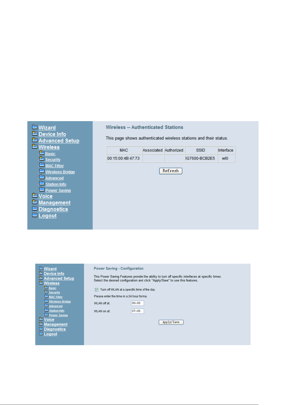
IG7600 Administration Manual
WMM (Wi-Fi Multimedia): Feature that improves the experience for audio, video and
voice applications over a Wi-Fi network.
WMM No Acknowledgement: When the “WMM No Acknowledgement" is enabled,
the receiver wil l not acknowledge rec eived packets during wireless packet trans mit. It is
suitable in the environment where communication quality is good and interference is
weak. It can improve transmission efficiency.
WMM APSD: WMM Automatic Pow er Save Del ivery. APSD is useful f or VoIP phon e to
achieve low power consumption.
6.5.6 Station Info Authenticated wireless stations and their status will be shown here. (Figure 6-43)
Figure 6-43. Wireless – Station Info
6.5.7 Power Saving
The Power Saving Features provide the ability to turn off specific interfaces at specific
times. (Figure 6-44)
Figure 6-44. Wireless – Power Saving
Copyright 2013 Tecom, Co. LTD. All rights reserved Page 68 of 127
Page 75

IG7600 Administration Manual
6.6 Voice
Use the Voice screen to configure the IG7600’s voice related parameters. It allows
system administrator to configure the following topics:
Phone
- Phone Extension
- Video Doorphone Settings
- Security Card Registration
- Programmable keys
Trunk
- IP Trunk
- Trunk DID
- Trunk Group
- Answering Position
- Call Routing
- Call Restriction
- Emergency Numbers
System
- Numbering Plan
- Service Mode
- Transmission
- SMDR
- UCD Call Log
Voicemail
- General
- Phone Extension
- Virtual Extension
- Update MOH File
- Update Voice File
- Holiday
- Advanced
NAT Traversal
Diagnostics
- Remote Maintenance
Registered Phone
The configurable items for each part would be described in the following.
6.6.1 Phone
Use the Phone screen to configure IG7600’s phone extension authentication and
configure the default line key setting.
6.6.1.1 Phone Extension
The IG7600 combines Proxy and Register servers in its application. All phones
registered to the internal Register server are set here. (Figure 6-45, Figure 6-46)
Copyright 2013 Tecom, Co. LTD. All rights reserved Page 69 of 127
Page 76
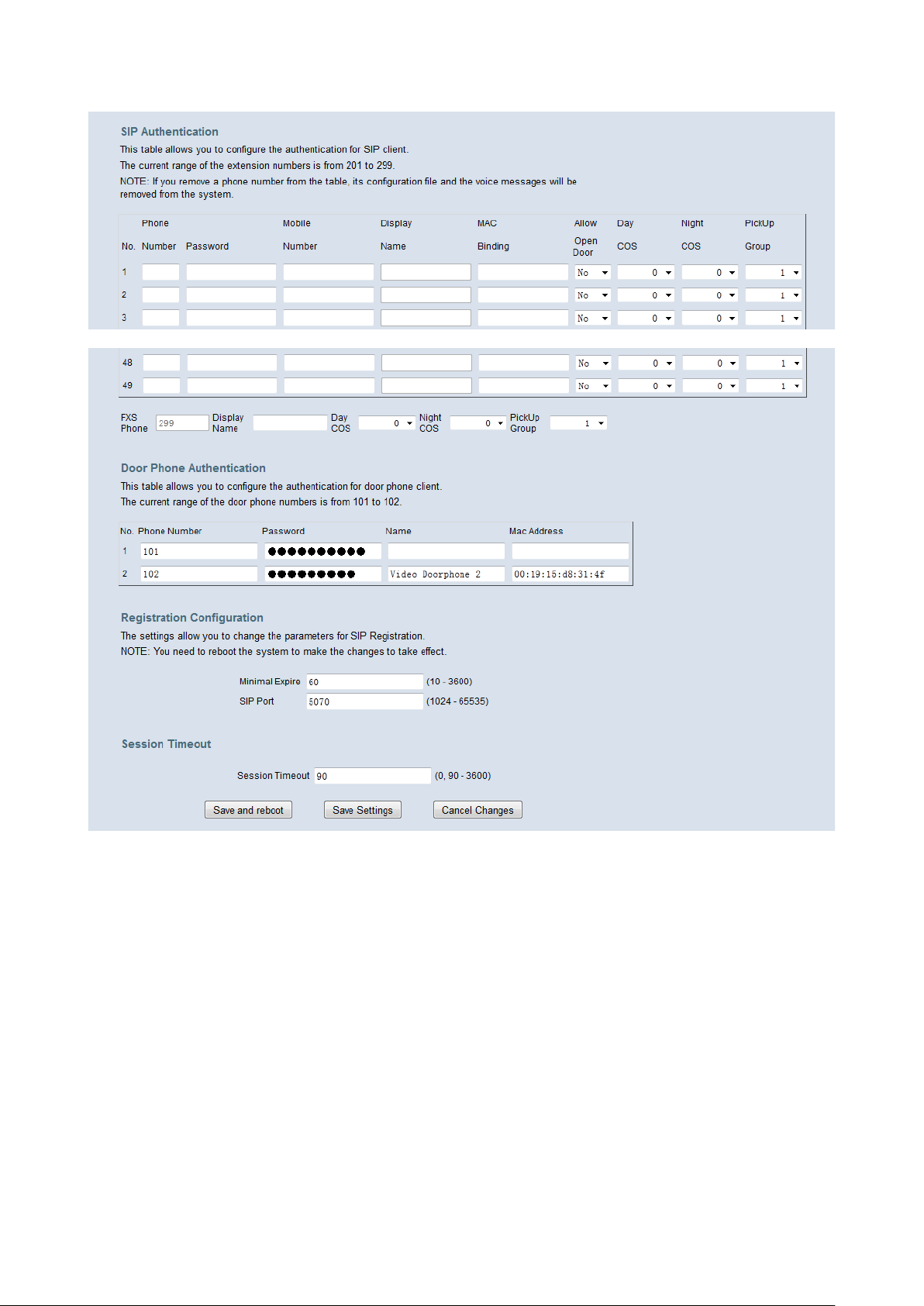
IG7600 Administration Manual
Figure 6-45. Voice – Phone – Phone Extensio n – 1
Figure 6-46. Voice – Phone – Phone Extensio n – 2
SIP Authentication: It provides 49 IP phones or Smart phones to register.
Phone Number: The phone number is a station number. If it conflicts with the setting
in Numbering Pla n, it fai ls to add or make the c hange. It s value r ange is l imited by S tart
Extension Number and End Extension Number settings in Numbering Plan page.
Password: The user password of this phone. The length is up to 24 digits or
characters. It’s used for Digest Authentication.
Mobile Number: If a smart phone registers to it, it can tell its mobile number to
IG7600.
Display Name. If a smart phone registers to IG with its display name, this column will
display the name.
Mac Binding: If a phone number is assigned by Plug-and-Play, the number is bound
to the extension’s M ac addr ess. Y ou ca n also add Mac bi ndi ng at IG 760 0’s w eb pag e.
Copyright 2013 Tecom, Co. LTD. All rights reserved Page 70 of 127
Page 77

IG7600 Administration Manual
If Mac binding exists, only the extension with this Mac address will be accepted to be
registered.
Allow Open Door: This field i s for us er t o con figur e if the extension is al low ed to open
door.
Day COS: The field assigns Class of Service for day mode operation. Acceptable
values are 0-7. At default, all extensions are unrestricted.
Night COS: The field assigns Class of Service for night mode operation. Acceptable
values are 0-7. At default, all extensions are unrestricted.
Pickup Group: The field assigns the extension to a specific pickup group. Each
extension can be assigned to one pickup g roup only . Four pick up groups are av ailable.
FXS Phone: It shows the FXS phone number. It’s programmed in Numbering Plan.
- Display Name: The FXS user’s Calling Name.
- Day COS: The FXS’s Class of Service for day mode operation.
- Night COS: The FXS’s Class of Service for night mode operation.
- Pickup Group: The FXS’s pickup group number
Door Phone Authentication:
It provides two door phones to register. Phone number, password and Mac Address
are for door phones to do Authentication. If Mac Address is empty, the entry is free to do
register for any door phon e, but if mac Address is filled with a special mac address, the
entry is bind to the door phone wit h this mac addr ess and only this door phone can use
this account to do register.
Registration Configuration:
The settings allow you to change the parameters for SIP Registration. You need to
reboot the system to make the changes to take effect.
Minimal Expire: Minimal registered period of IP phone.
SIP Port: The IG7600 listens for requests on the SIP port. This port is used for UDP
application and 5070 is its default value. The port number cannot be the same as the
“Local SIP Port for IP Trunk” for IP Trunk application.
Session Timeout:
The settings allow you to change the parameters for session timer.
Session Timeout: It defines how long IG7600 sends “UPDATE” packet to extension.
6.6.1.2 Video Doorphone Settings
This page allows you to configure the settings for door phone’s features.(Figure 6-47)
Copyright 2013 Tecom, Co. LTD. All rights reserved Page 71 of 127
Page 78

IG7600 Administration Manual
Figure 6-47. Voice – Phone – Door Settings
Door Phone: Door Phone Numbers.
Status: Door Phone Status(Disconnected/Closed/Opened)
Start Time/ End Time: During this period Door Phone should turn on its LED light.
Open Time: This is the time that door phon e del ays before op en the door w hen r eceiv ing
an open door request.
Ring Time: When a call is not answered after this time. The ringing will stop
automatically.
Talk Time: When a call is answered and is last for 60(Default value) seconds. The call
will be cut off by the IG.
Speaker/ MIC Volume: Volume of door phone’s speaker and microphone can be
modified here.
Open Door Password: This password is used when user wanted to open door.
Answer Position: Here is to set the answer position of a door phone call, any call from
this door phone will be answered by the destination you’ve set.
Allow Remote IP Phone Open Door: If you want to open door on remote IPP you
should enable the function first which is disabled by default, this checkbox is for you to
enable it.
Copyright 2013 Tecom, Co. LTD. All rights reserved Page 72 of 127
Page 79
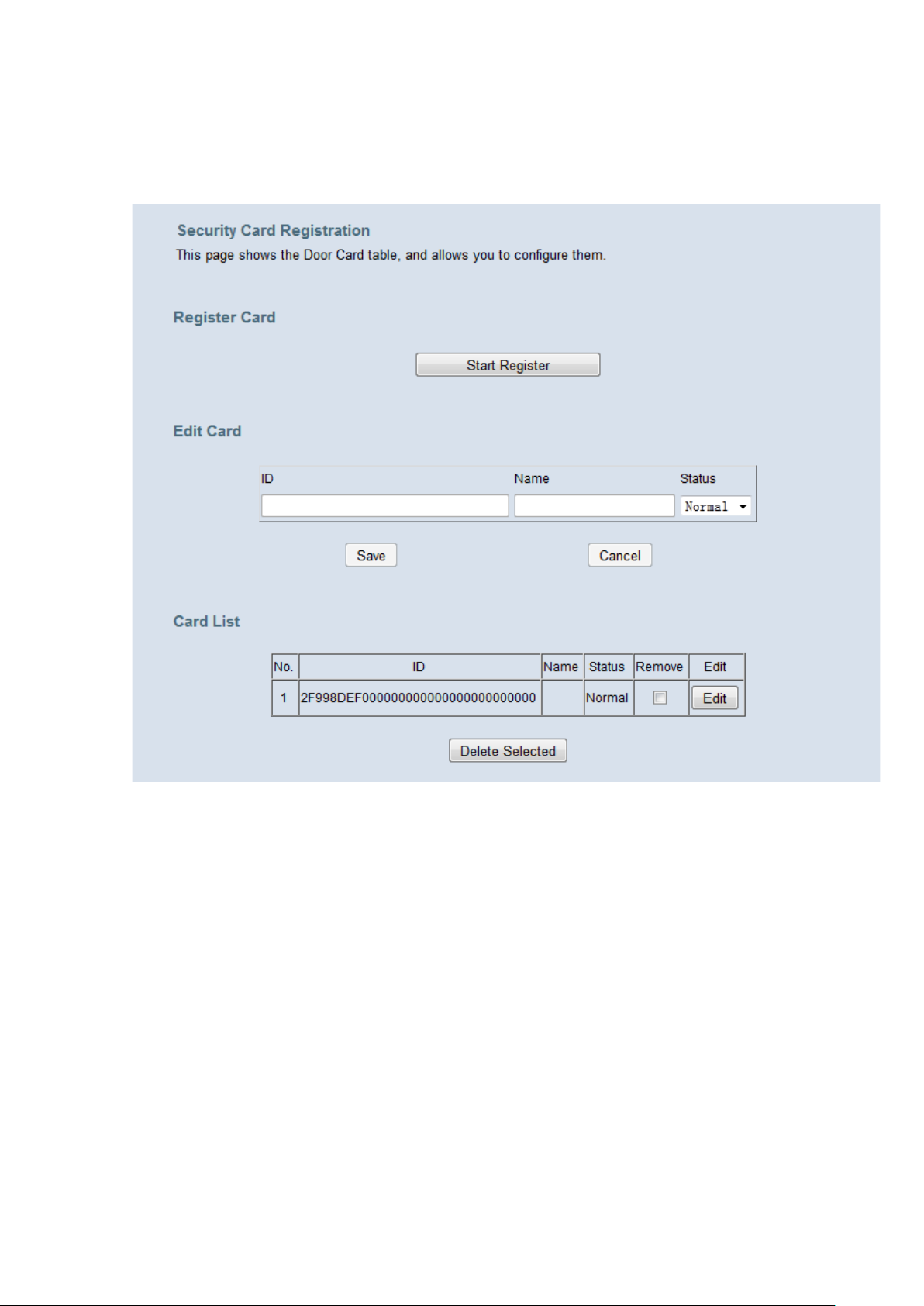
IG7600 Administration Manual
6.6.1.3 Security Card Registration
This page shows the Door Card table, and allows you to configure them.(Figure 6-48)
Figure 6-48. Voice – Phone – Door Card
When you want to add new door card to this table, you should push the “Start
Register” button to start the register process and swipe the card. At most you can add
32 cards. You can change a card’s name and status in the table by pressing the edit
button
6.6.1.4 Programmable keys
This page allow s y ou to con figur e th e de fault sett ings for IP phone’s programmable Key s.
While a new-allocated IP phone is registering to IG7600, IG7600 will send these settings
to the phone. You can select Extension, Trunk, Call Park, Feature key, Do Not Disturb,
Live Record, Virtual Mailbox and Others to these Programmable keys. (Figure 6-49)
Line keys are for IP Trunk setting is only for M54(-i)’s 4 line keys. By default it is disabled
and the 4 line key s on M54(-i) wi ll show the st atus of PSTN Tru nk; Y ou ca n e nable i t her e.
If you enable it, M54(-i) will show the status of IP Trunk on its 4 line keys.
Programmable Keys 1-16 are specially for M22 and M62.
EDM Key 1-24 can be applied to IP2 06 1’s or M22 and M62’s EDM.
Copyright 2013 Tecom, Co. LTD. All rights reserved Page 73 of 127
Page 80
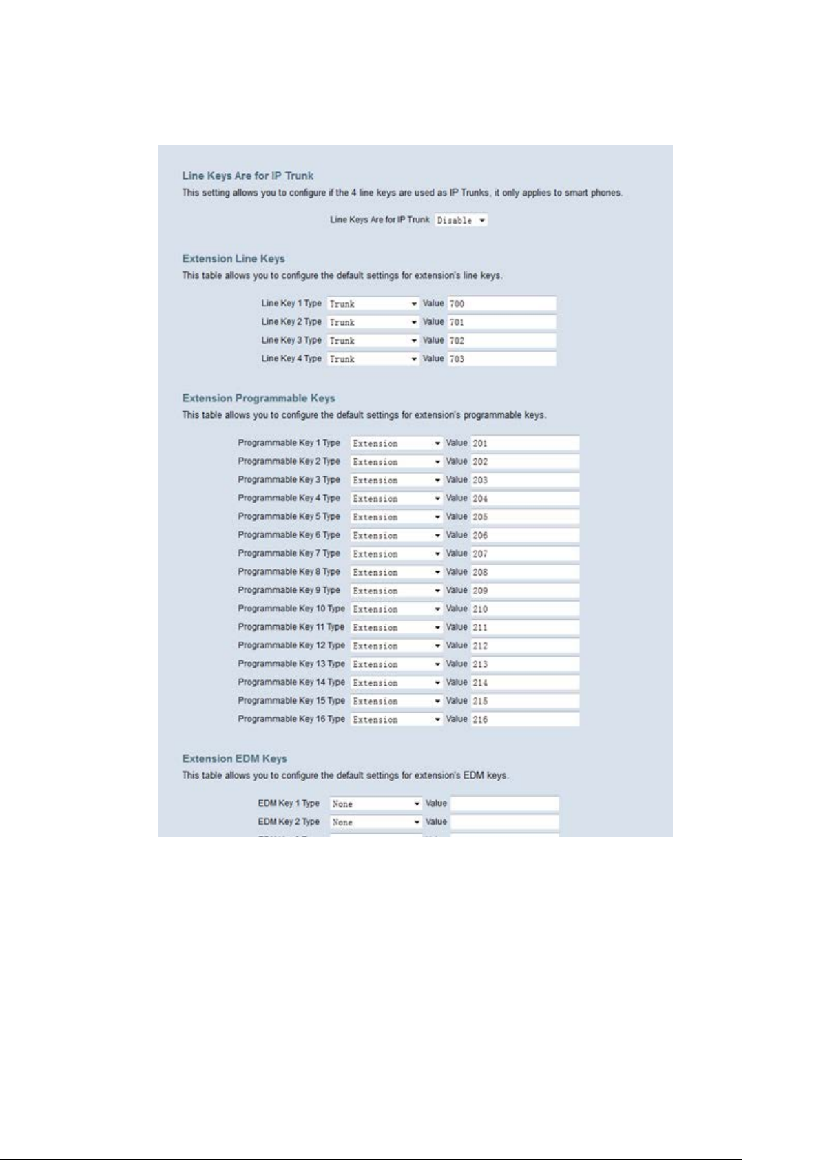
IG7600 Administration Manual
Auto Hold: When you are using a line and press another key, IG7600 can hold the
original line. Select “Enable” to open this function.
Copyright 2013 Tecom, Co. LTD. All rights reserved Page 74 of 127
Page 81
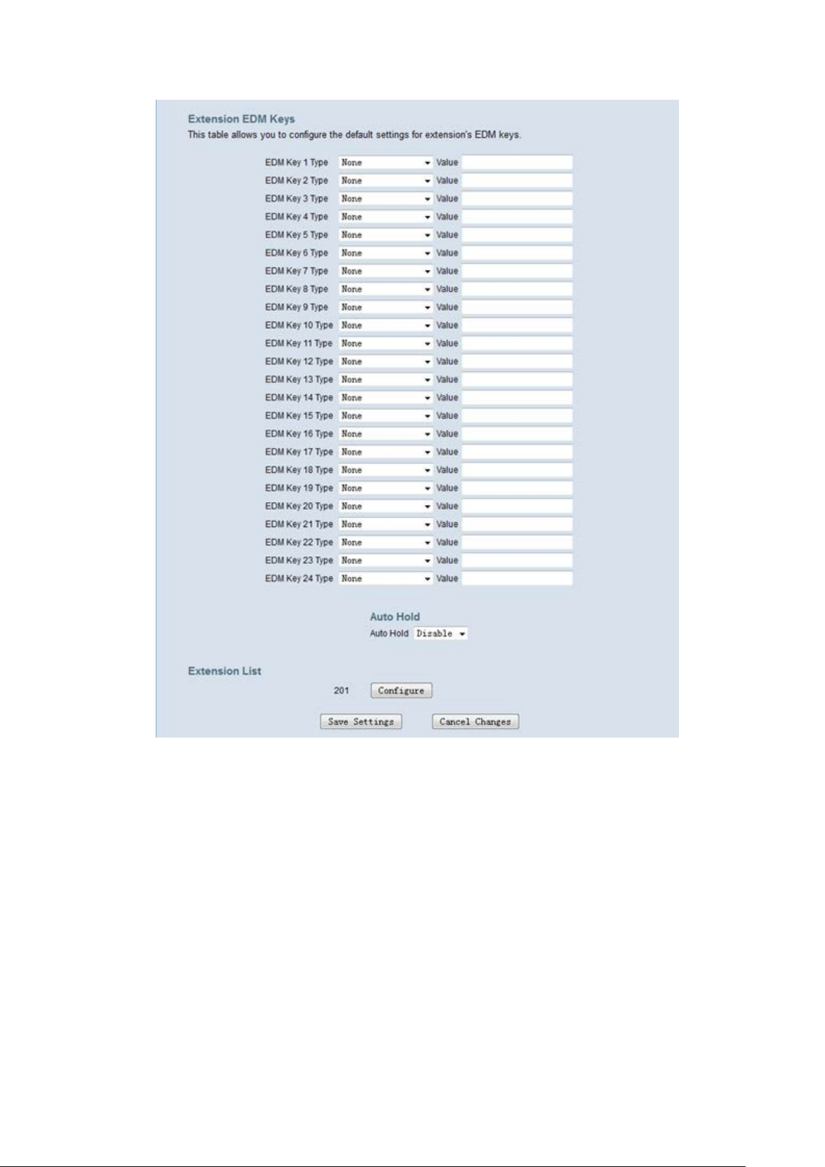
IG7600 Administration Manual
Figure 6-49. Voice – Phone – Programmable keys
When there are IP phones registered to IG7600, you can configure their key setting. In
Extension List, press “Configure” to configure keys of the specific phone.
Follow Gateway Settings: Use default IG7600 key setting for the IP phone. If you
check the checkbox, all the input operations are disabled, and the Ext’s
programmable keys settings will use the Gateway settings. You can configure the
settings manually only if the check box “Follow Gateway Settings” is not checked.
Copyright 2013 Tecom, Co. LTD. All rights reserved Page 75 of 127
Page 82
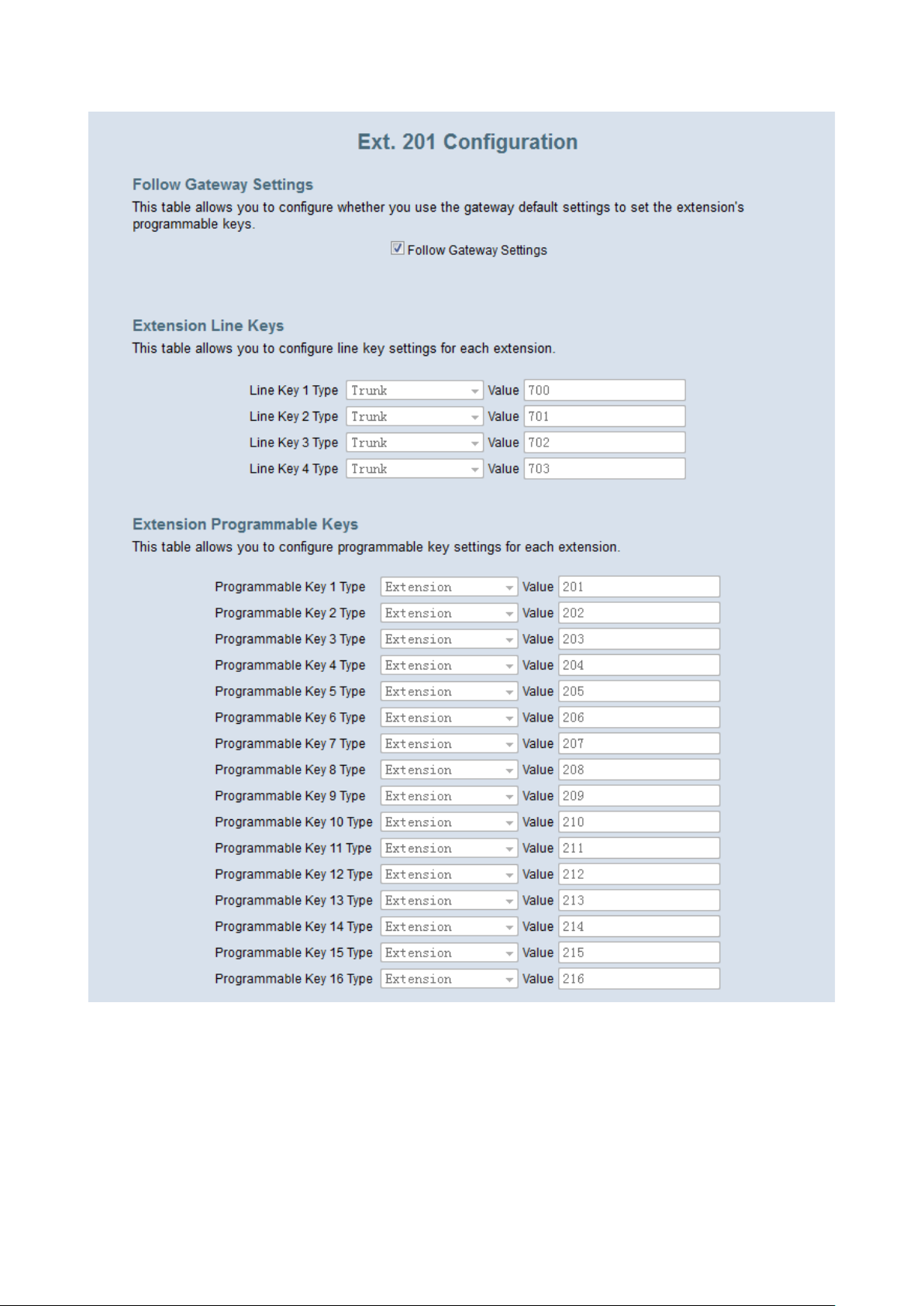
IG7600 Administration Manual
Copyright 2013 Tecom, Co. LTD. All rights reserved Page 76 of 127
Page 83
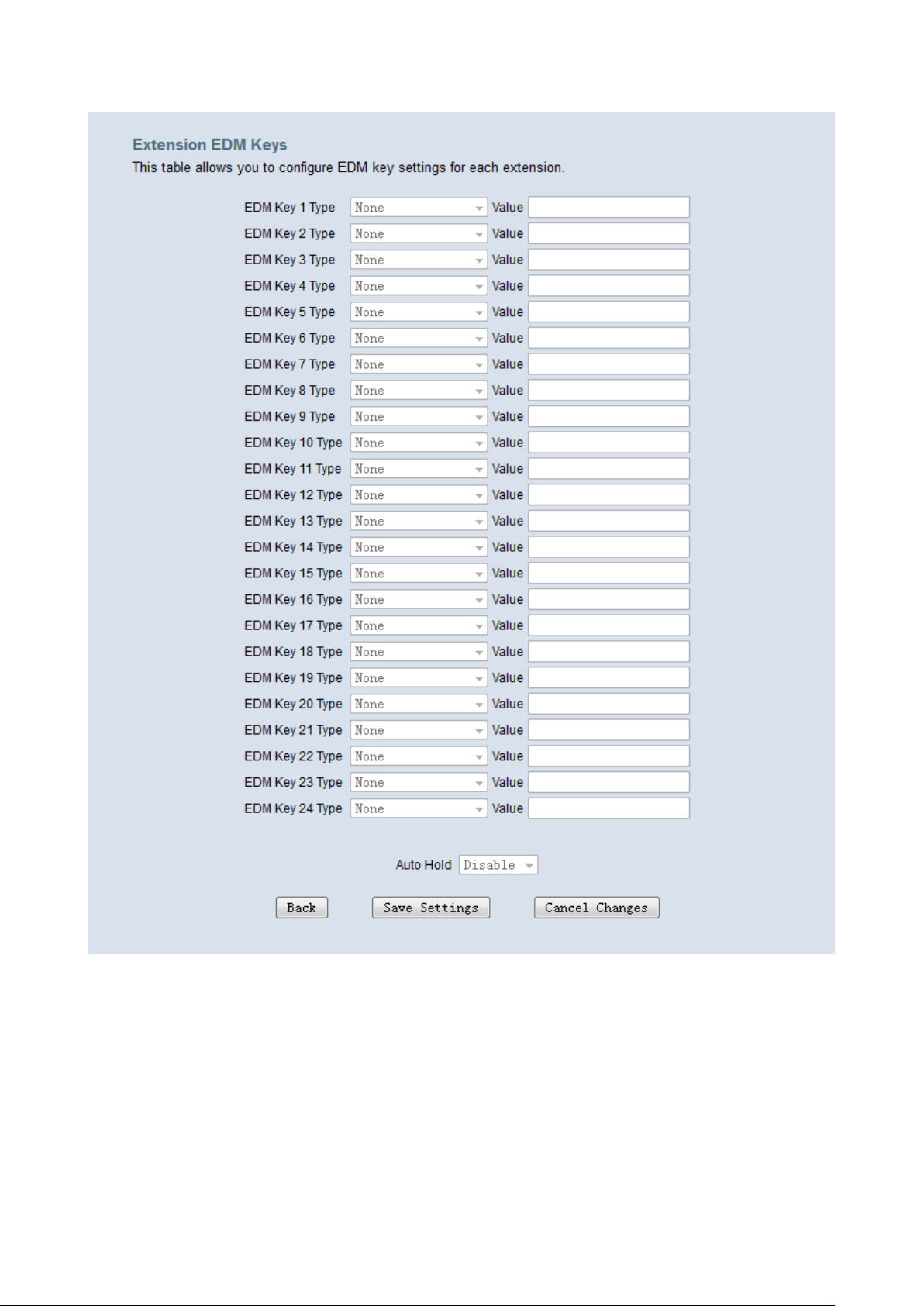
IG7600 Administration Manual
Figure 6-50. Voice – Phone – Extension Linekey-Configure
6.6.2 Trunk
Use the Trunk screen to configure the PSTN/IP Trunk function related parameters. It is
separated into 7 parts:
IP Trunk
Trunk DID
Trunk Group
Answering Position
Call Routing
Call Restriction
Copyright 2013 Tecom, Co. LTD. All rights reserved Page 77 of 127
Page 84
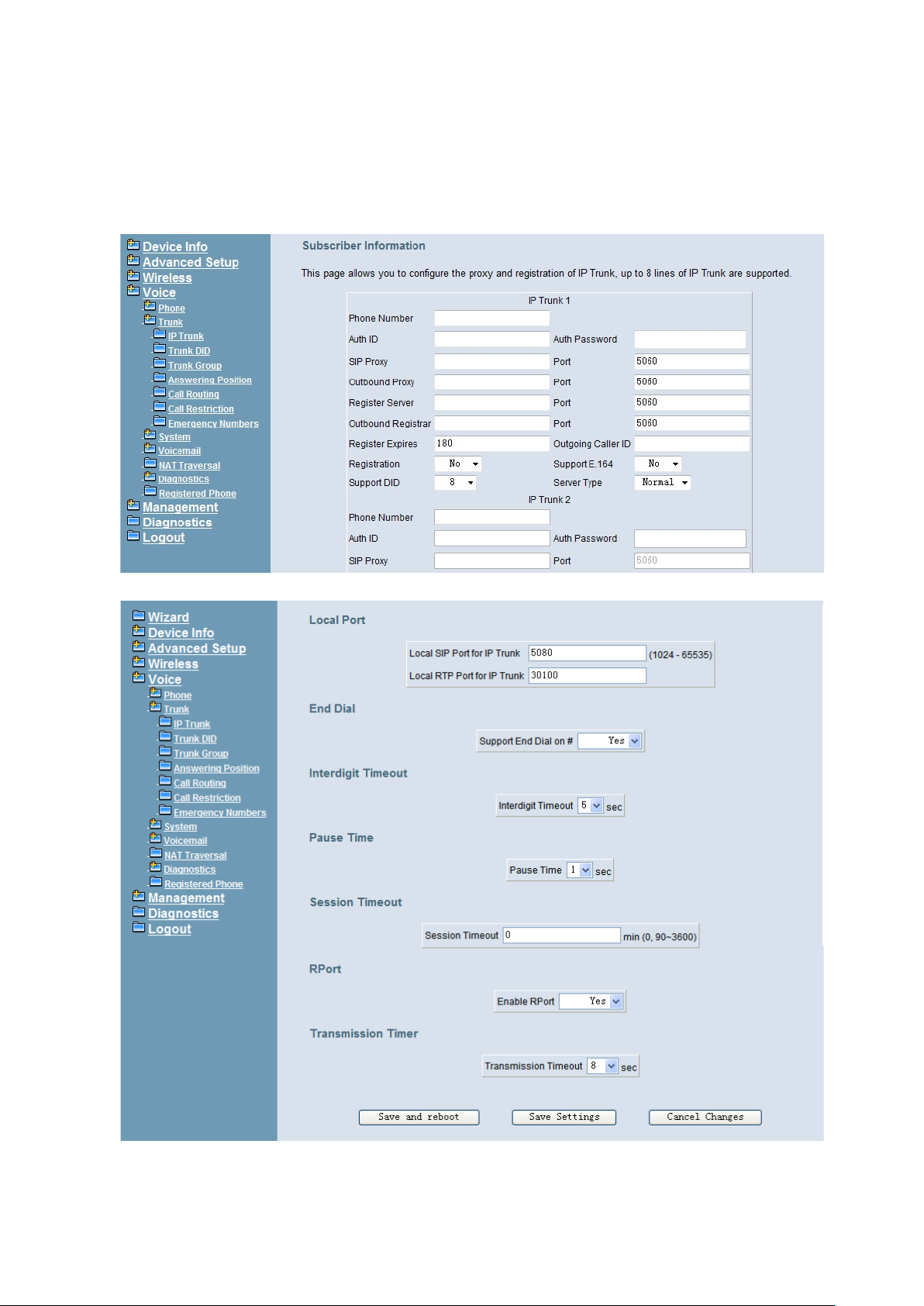
IG7600 Administration Manual
Emergency Numbers
6.6.2.1 IP Trunk
This page allows you to configure the Proxy and Register server of IP Trunks; up to 12
lines of IP Trunk are supported. (Figure 6-51, Figure 6-52)
Figure 6-51. Voice – Trunk – IP Trunk – 1
Figure 6-52. Voice – Trunk – IP Trunk – 2
Copyright 2013 Tecom, Co. LTD. All rights reserved Page 78 of 127
Page 85

IG7600 Administration Manual
Subscriber Information:
Phone Number: It’s the assigned phone number from uplink server.
Auth ID: The Account ID of registration to uplink server. It’s used for Digest
Authentication.
Auth Password: The Password of registration to uplink server. It’s used for Digest
Authentication.
SIP Proxy: The position of uplink SIP proxy server. IP address and domain na me are
all supported.
SIP Proxy Port: The SIP signal port of uplink registrar server.
Outbound Proxy: The address of upli nk outboun d proxy s erver. All sip r equest pack et
will be sent to this server that will determine their next hops.
Outbound Proxy Port: The SIP signal port of uplink outbou nd pr oxy server.
Register Proxy: The position of uplink register server. IP address and domain name
are all supported.
Register Proxy Port: The SIP signal port of uplink registrar server.
Outbound Registrar: The address o f uplink outb ound Registrar serv er. All
REGISTER packets will be sent to this server that will determine their next hops.
Outbound Proxy Port: The SIP signal port of uplink outbou nd reg i strar server.
Register Expires: It’ s the time for IG7600 se nds R EGISTER to uplink reg is ter ser ver.
It counts based on second.
Outgoing Caller ID: It’s used as the Caller ID for the outgoing calls.
Registration: If “Registration” is No, the IP Trunk will not send REGISTER to the
Register Proxy.
Support E.164: If “Support E.1 64” is Y es, the IP Tru nk follow s E.16 4 format to se nd to
outgoing phone number.
Support DID: If “Support DID” is a digit, the IP Trunk is used in DID operation. The IP
Trunks from the current one to the specified IP Trunk are applied in the specified
account. For example, if the setting is “5” in IP Trunk 1, the account is applied for IP
Trunk 1 to 5. It means it can have 5 concurrent calls in the account.
Ser ver Type: If “Server Type” is CHTM, and if the Caller ID of the incoming Trunk call
exists, IG7600 will use the Caller ID in From and P-Asserted-Identify header in the
outgoing IP Trunk call.
Local Port:
Local SIP Port for IP Trunk: SIP control signal packet Port of IP Trunk Client. The
port number cannot be the same as the “SIP Port” for Extension Registration.
Local RTP Port for IP Trunk: Real-Time Protocol packet Port of IP Trunk Client. It’s
the start RTP port address for these IP Trunks.
End Dial:
If “Support End Dial on #” is Yes, outgoing number from IP trunk will be sent out
immediately after pressing pound key (#).
Interdigit Timeout:
Copyright 2013 Tecom, Co. LTD. All rights reserved Page 79 of 127
Page 86
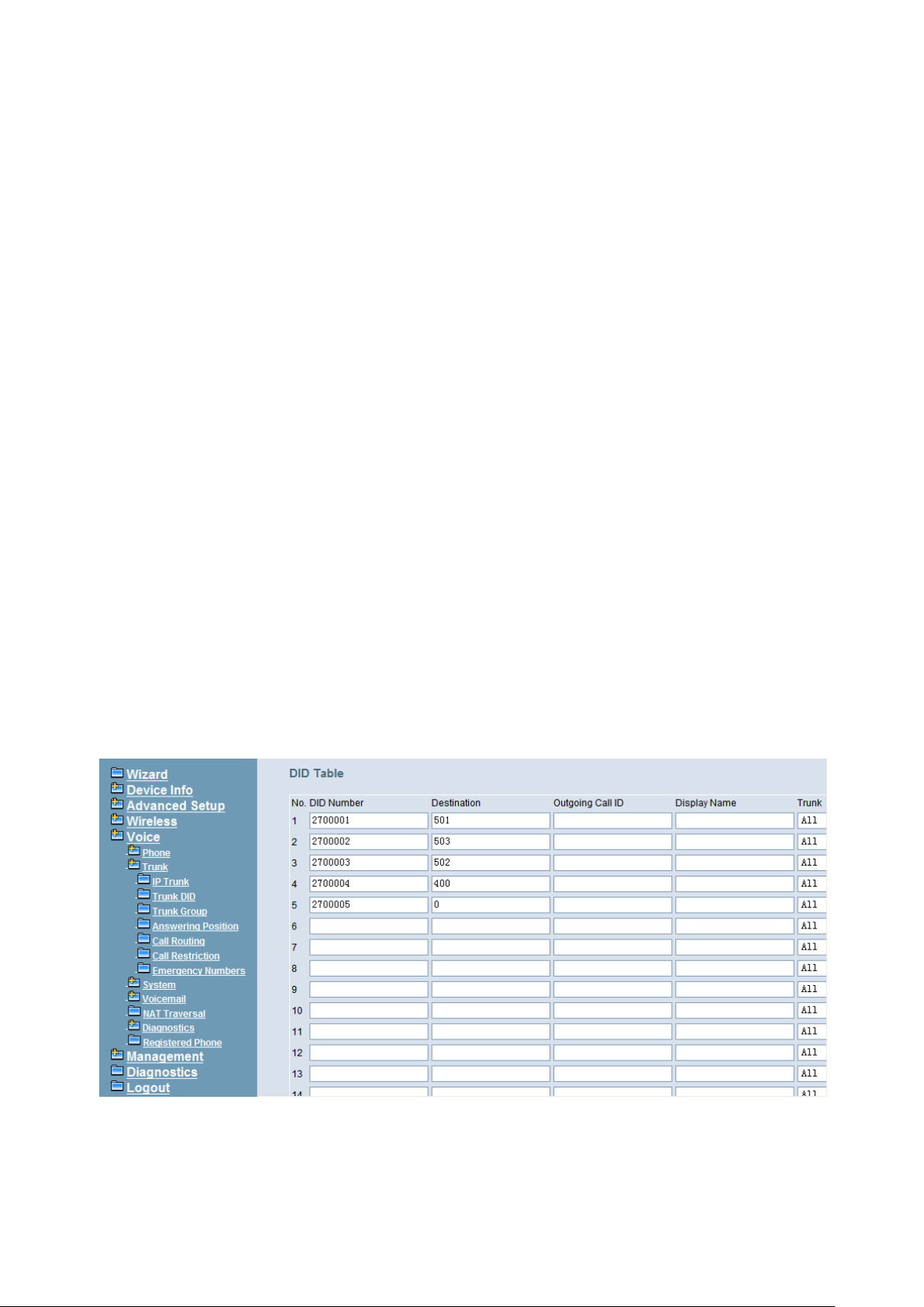
IG7600 Administration Manual
If there is no any dialed number after the setting time, the number will be sent out
immediately. Its range is form 2 to 9 seconds.
Pause Time:
The pause time of alphabet “p” in the process of call dialing
Session Timeout:
It means the longest communication time for IP trunks, zero means no restriction.
RPort:
When client is behind a NAT, the rport and received filed can allow SIP proxy to
append the public IP address and port of NAT and transfer SIP message correctly.
Choose “Enable” to use this function.
Transmission Timer:
If an outgoing trunk call matches more than one entries in Call Routing Table, if the
former matched entry gets timeout after this specific seconds, IG7600 will try the next
one.
6.6.2.2 Trunk DID
The table offers its individual phone number for each extension (Figure 6-53). Up to
100 DID number are supported.
DID Number: It’s the assigned phone number from uplink server for incoming calls. If
“Outgoing Call ID” is null, it will be as Caller ID number for outgoing calls also.
Destination: the specified ringing extension(s) for the individual DID phone number.
Outgoing Call ID: It’s the assigned Caller ID number from uplink server.
Display Name: the specified extension user name for the individual number. It will be
used as Caller ID name in the outgoing calls.
Trunk: The DID item is for the specified trunk(s). If it’s “All”, the DID number can be
applied to all IP Trunks.
Figure 6-53. Voice – Trunk – Trunk DID
Copyright 2013 Tecom, Co. LTD. All rights reserved Page 80 of 127
Page 87
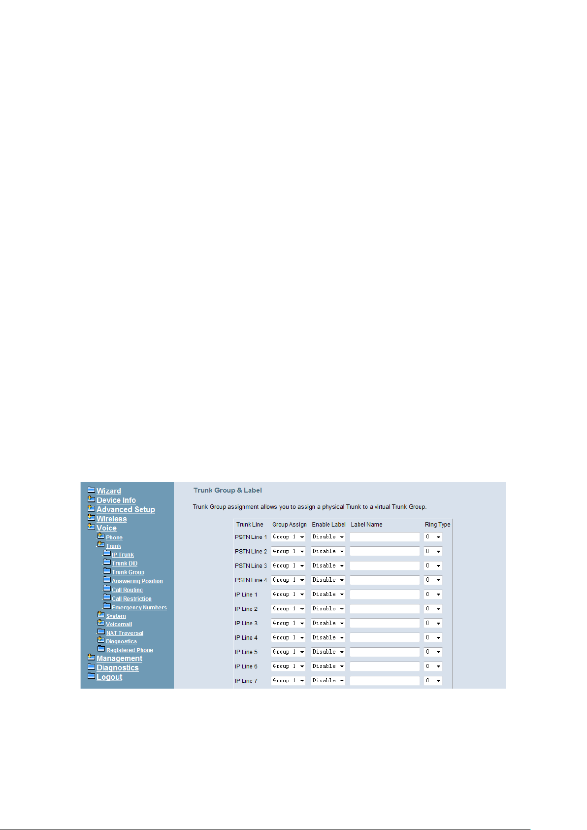
IG7600 Administration Manual
6.6.2.3 Trunk Group
This page allows you to configure the virtual Trunk Group. Up to 4 Trunk Groups are
supported. (Figure 6-54, Figure 6-55)
Trunk Group & Label Name:
This item allows you to assign physical Trunk to virtual Trunk Group. For four PSTN
lines and four IP lines you can choose from Group1 to Group 4.
PS: There is a special trunk group named Group ALL, all lines are considered
to be a member of the group.
Label Name:
This item allows you to configure a specified string as incoming Caller ID name. For
PSTN incoming call, it will be applied if no Caller ID received in the call. For IP Trunk
call, it will replace the original Ca ller ID name.
Ring Type:
The specific r ing type ass igned to the Trunk Line is the ring type heard w hen the Trunk
Line rings. The ring type is applied for IP2061/M22/M62 pho ne onl y .
Trunk Group Priority:
This Item allows you to define 4 Trunk Groups and Group All’s interior priority.
Access Priority:
This Item allows you to define 4 Trunk Groups and Group All's interior priority. For
the five groups you can choose IP first or PSTN first. This will take effect if call
routing entry’s destination has been set as Group choice.
Search Order:
You can choose the s earch ord er to use the s pecified access priority. F or example,
when you choose I P First and increase, IG 7600 will try to find an av ailable IP Tr unk
and search from the first IP Trunk in the Group.
Figure 6-54. Voice – Trunk – Trunk Group – 1
Copyright 2013 Tecom, Co. LTD. All rights reserved Page 81 of 127
Page 88
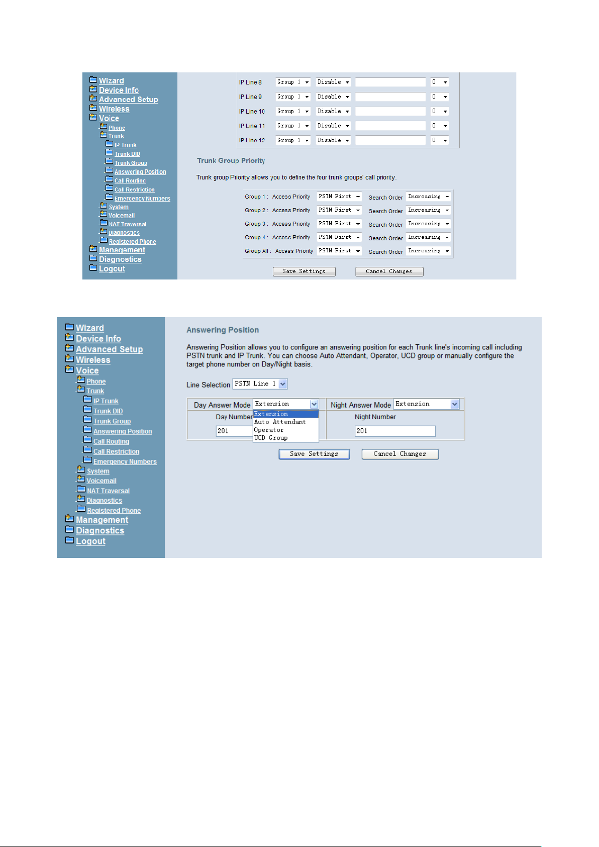
IG7600 Administration Manual
Figure 6-55. Voice – Trunk – Trunk Group – 2
6.6.2.4 Answering Position
Figure 6-56. Voice – Trunk – Answering Posit ions
This page allows you to configure an answering position for each Trunk line's incoming
call including PSTN trunk and IP Trunk. You can choose Auto Attendant, Operator, UCD
Group or manually configure the target extension phone number on Day/Night basis.
(Figure 6-56)
Choose Auto Attendant, you can configure an AA Menu number. An idle VAA will
auto-answer this incoming trunk call.
Choose Extension, you must configure the target phone number on Day/Night basis.
Choose UCD Group, you can configure an UCD group. The maximum phones for one
UCD group are 50.
Choose Operator, the incoming trunk call will be redirected to Operator.
Copyright 2013 Tecom, Co. LTD. All rights reserved Page 82 of 127
Page 89
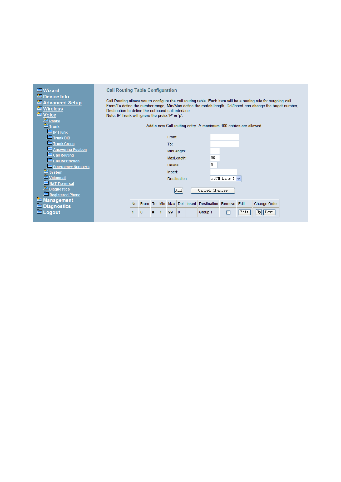
IG7600 Administration Manual
6.6.2.5 Call Routing
This page allows you to configure the call routing table. A maximum 100 entr i es ar e
allowed. Each entry is a routing rule for outgoing call. From/To define the number range,
Min/Max define the match length, Del/Insert can change the target number, Destination
to define the outbound call interface. (Figure 6-57)
Figure 6-57. Voice – Trunk – Call Routing Table – 1
6.6.2.6 Call Restriction
This page allows you to configure the Call Restriction Table. A maximum 40 entries are
allowed.
There are two types of Call Restriction Table, Allowed Table and Denied Table (Figure
6-58):
Each entry has an interval, which is made up of From and To, establishing a numeric
range. For example, an entry of “From 1700”, “To 1800” includes the following range of
numbers as the leading: 1700, 1701, 1702 …1799, 1800. Each From/To entry can be
from 1 to 13 digits long and may contain any digit 0-9, *, #, X/x (representing any digit)
and +. The “From” entry must be less than or equal to the “To” entry.
If the Trunk Access value is set to “Y”, the entry is valid when the trunk is accessed
previously. If the field is set to “N”, the entry is valid when the trunk is NOT accessed
previously (The call ma y be made through Call Routing Table). If the opti on is set to “YN” ,
the entry is valid no matter the trunk is accessed or not previously.
The COS value defines COS values that are cons i dered to be matched for t his entr y. For
the Allowed Table, the entry is matched when the extension’s COS value is smaller than
or equal to it; while for the Denied Ta ble, the entr y is matched when the extension’s COS
value is larger than or equal to it.
Table Type decides into which table this entry will be added.
Priority decides which table w ill be checked fir st. If Priority is “Allowed”, IG7600 will check
Allowed Table first, i f a ny entry is matche d IG760 0 w ill s earch D enied T able t hen, the c al l
Copyright 2013 Tecom, Co. LTD. All rights reserved Page 83 of 127
Page 90
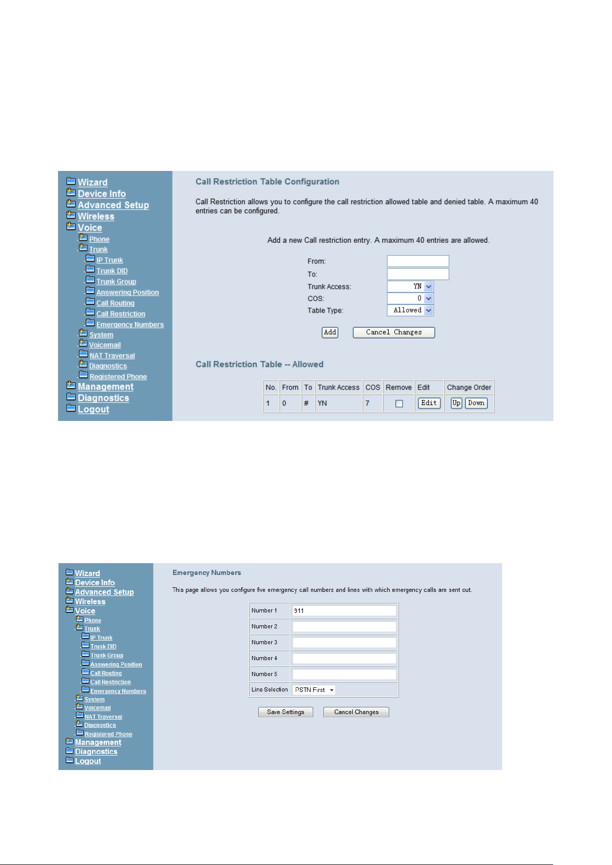
IG7600 Administration Manual
can be made only when there is any matched entry found in Allowed Table and there is
no any matched entry found in Denied Table. If Priority is “Denied”, IG7600 will check
Denied Table first, if an y entr y is matched IG 7600 w il l sear ch All owed Table t hen, the c all
will be forbidden only when there is any matched entry found in Denied Table and there
is no any matched entry found in Allowed Table.
Figure 6-58. Voice – Trunk – Call Restriction
6.6.2.7 Emergency Numbers
When they dial a pre-configured emergency number, any user can make an emergency
call regardless of call routing table, call restriction, and station lock. Notice: The numbers
of emergency dial must not collide with the numbers in Numbering Plan.
This page allows you configure five emergency call numbers and lines with which
emergency calls are sent out. (Figure 6-59)
Figure 6-59. Voice – Trunk – Emergency Dial
Copyright 2013 Tecom, Co. LTD. All rights reserved Page 84 of 127
Page 91
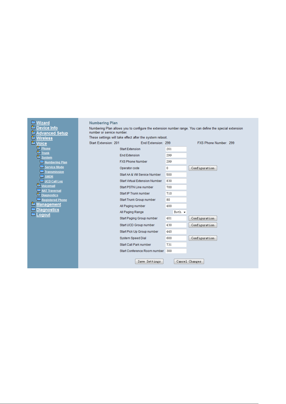
IG7600 Administration Manual
6.6.3 System
Use the System screen to configure the System function related parameters. It is
separated into five parts:
Numbering Plan
Service Mode
Transmission
SMDR
UCD Call Log
6.6.3.1 Numbering Plan
Figure 6-60. Voice – System – Numbering Plan
This page allows you to configure extension number range. You can also define some
special service numbers in the table. (Figure 6-60)
Start extension: It’s the start phone number of system internal extension. All valid
extension number can’t be smaller than it.
End extension: It’s the end phone number of system internal extension. All valid
extension number can’t be greater than it. If receiving an IP2061/M22/M62’s Plug &
Play request, IG7600 will allocate the first unused numb er from this l imi ted reg i on.
FXS Phone Number: It determines the FXS phone number.
Operator speed-dial number: If di al this number, t he operator extensi on wil l be called.
The length is limited on 1 character.
When you press the “Configuration” button, the operator-related settings can be
configured: (Figure 6-61)
Copyright 2013 Tecom, Co. LTD. All rights reserved Page 85 of 127
Page 92
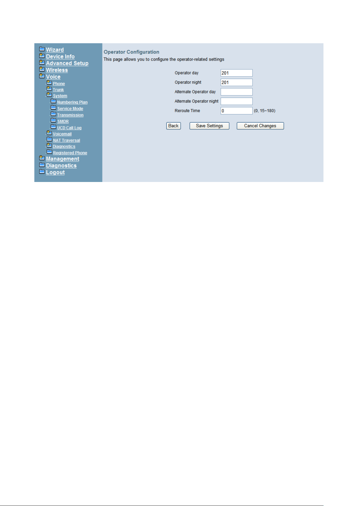
IG7600 Administration Manual
Figure 6-61. Voice – System – Numbering Plan – Operator Configuration
Operator day: It’s the system operator number during day. If dial Operator
speed-dial number, this extension will be called during day.
Operator Night: It’s the system operator number during night. If dial Operator
speed-dial number, this extension will be called during night.
Alternate Operat or day : When the Operator duri ng day does not answer a cal l, the
call will be rerouted to alternate operator during day.
Alternate Operator night: When the Operator during nig ht do es not answ er a c all ,
the call will be rerouted to alternate operator during night.
Reroute Time: Set the length of operator no answer time to reroute to alternate
operator. The time is applied to the call for alternate operator also. If alternate
operator doesn’t answer the cal l in the Rer oute time, t he call is r eroute to Op erator’s
Voice Mail box. “0” means it keeps ringing to the operator.
Start AA&VM Service Number: IG7600 provides 10 menus. If dial this number,
internal user can enter IG7600’s voicemail system and do some operations such as
listening personal message.
Start Virtual Extension Number: IG7600 provides virtual extension number for the
members not works in the office, or as a secondary mailbox.
Start PSTN Line number: IG7600 provides 4 PSTN lines at most. Every line has its
own internal alias nu mber. You can dial th ese numbers directl y to access PSTN trunk s.
Start IP Trunk number: IG7600 provides 12 IP Trunk lines at most . E v ery line has its
own internal alias number. You can dial these numbers directly to access IP Trunks.
Start Trunk Group number: IG7600 provides 4 trunk groups at most. If dialing trunk
group number,
All Paging number: If dialing this number, all int ernal IP2061/M22/M62 w ill be page d.
All Paging range: You can select the range of the paged extensions. If it’s LAN, it
pages the IP2061/M22/M62 on IG7600’s LAN side. If it’s WAN, it pages the
IP2061/M22/M62 on IG7600 WAN si de, bu t und er th e same Router w i th I G76 00. If it’s
Both, it pages the all IP2061/M22/M62 on LAN and WAN.
Copyright 2013 Tecom, Co. LTD. All rights reserved Page 86 of 127
Page 93
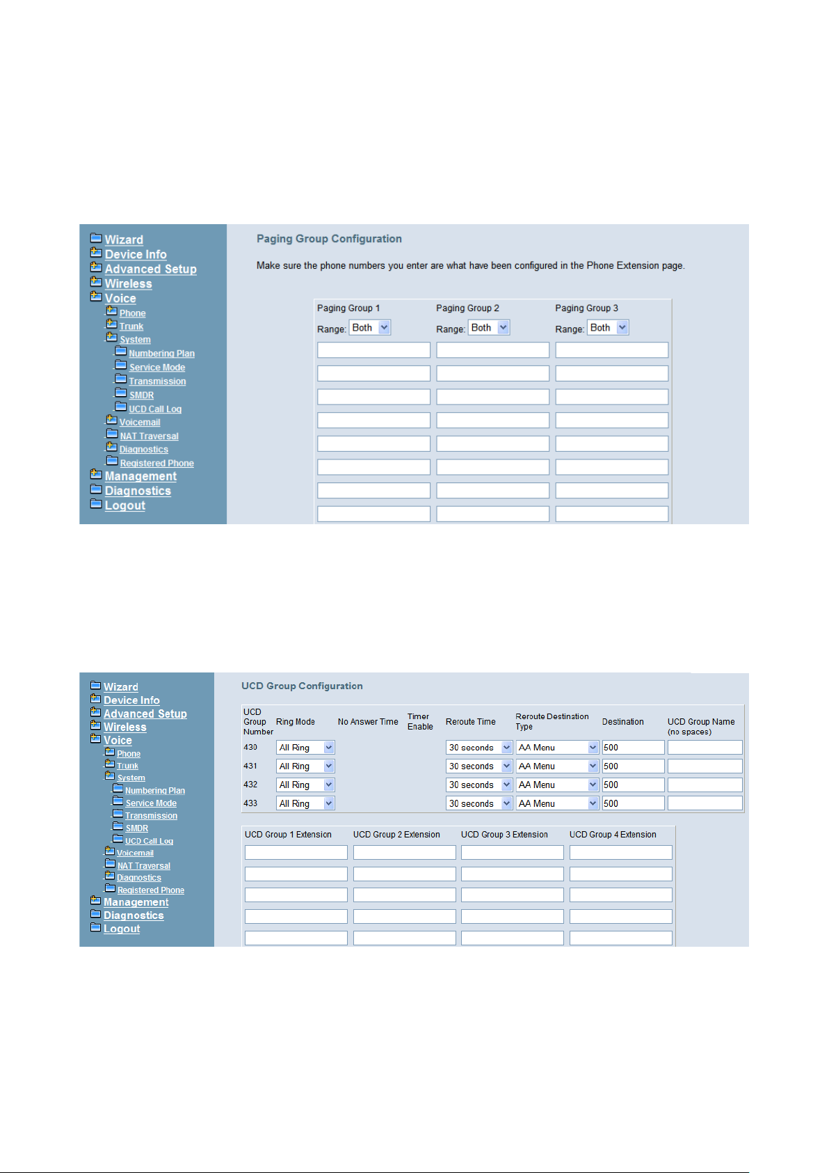
IG7600 Administration Manual
Start Paging Group number: 3 paging groups are defined in IG7600. If dialing a
Paging Group number, the call will page to predefined internal IP phones. It can also
select the Range l ike Al l Paging N umber. The maximum p hones for each pag ing group
are 49.
While pressing “Configuration” in “Start Paging Group number”, it shows Paging
Group Configuration screen. (Figure 6-62)
Figure 6-62. Voice – System – Numbering Plan – Paging Group
Start UCD Group number: 4 UCD groups are defined in IG7600. The maximum
phones for each UC D g r oup are 50. If one UCD Group is assigned to Answering
Position of certain line, when there is an incoming trunk call, extensions of the UCD
group will be called and ringing
While pressing “Configuration” in “Start UCD Group number”, it shows UCD Group
Configuration screen. (Figure 6-63)
Figure 6-63. Voice – System – Numbering Plan – UCD Group
There are seven items to be decided.
For Ring Mode, IG7600 supports “All Ring”, “Linear” and “Distributed” mode. The “All
Ring” mode is no needed to use “No Answer Time” and “Timer Enable”.
Copyright 2013 Tecom, Co. LTD. All rights reserved Page 87 of 127
Page 94
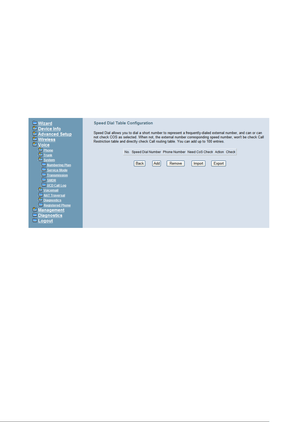
IG7600 Administration Manual
For other items, if “Timer Enable” is YES, the incoming call will be transferred to
another UCD Group’s member every “No Answer Time”. If NO, the call will ignore “No
Answer Time” and finally reroute to “Reroute Destination” after “Reroute Time”.
“Reroute Destination” can be an Auto Attendant Menu, an extension, a virtual
extension, or phone extension’s mailbox. “UCD Group Name” is shown on the phone
when receiving the UCD Group call.
Start Pickup Group number: The start number is used as All Pickup number. The
next 4 numbers are used for the four pickup groups.
System Speed Dial: Speed Dialing allows you to store frequently outgoing numbers.
There are 100 sets to be configured. Extension’s Class of service (COS) can also be
checked or not. (Figure 6-64)
Figure 6-64. Voice – System – Speed Dial
Start Call Park Number: IG7600 supports to park 4 trunk calls maximum. The Call
Park number can be programmed on the line keys.
Start Conference Room Number: Conference Room Number allows the users to
build a conference conversation.
6.6.3.2 Service Mode
This page allows you to configure the Day/Night/Time service mode. You can also
customize the working time manually for each weekday.
If you choose Time Mode, it’s for the specified day of week. The time is entered in
24-hour format. Valid entr i es are 00: 00 to 23: 59 in 1-minute increments. Th e fir st f our
digits are for the start time. The last four digits are for the end time. (Figure 6-65)
Working Hours: It’s applied in Answering Positions and Auto Attendant Greeting.
Lunch Break: It’s applied in Auto Attendant Greeting
Copyright 2013 Tecom, Co. LTD. All rights reserved Page 88 of 127
Page 95
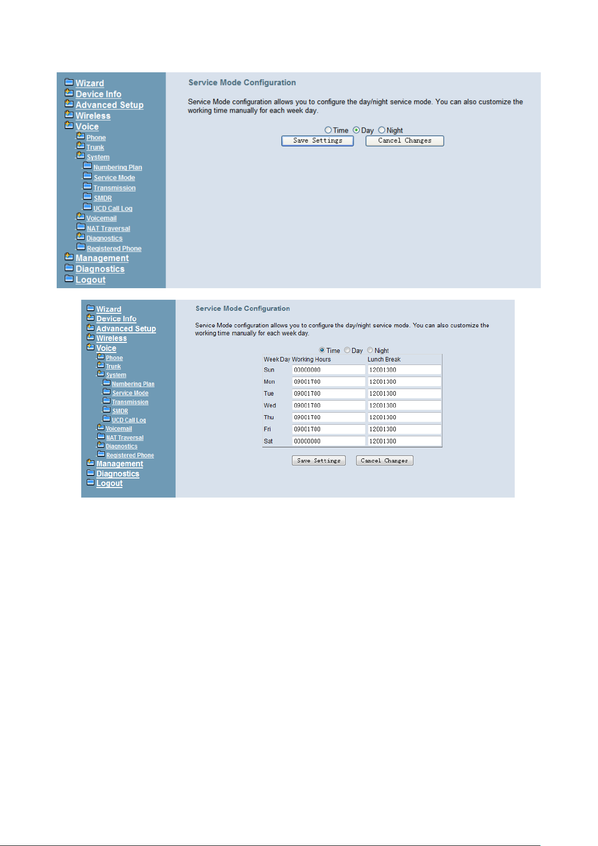
IG7600 Administration Manual
Figure 6-65. Voice – System – Service Mode
Figure 6-66. Voice – System – Service Mode
6.6.3.3 Transmission
This page allows you to configure the Audio, FXS, and FXO settings. Click “Save
Settings” button to save the new configuration. (Figure 6-67)
Copyright 2013 Tecom, Co. LTD. All rights reserved Page 89 of 127
Page 96
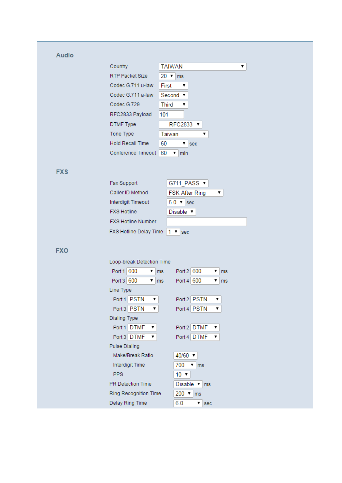
IG7600 Administration Manual
Copyright 2013 Tecom, Co. LTD. All rights reserved Page 90 of 127
Page 97
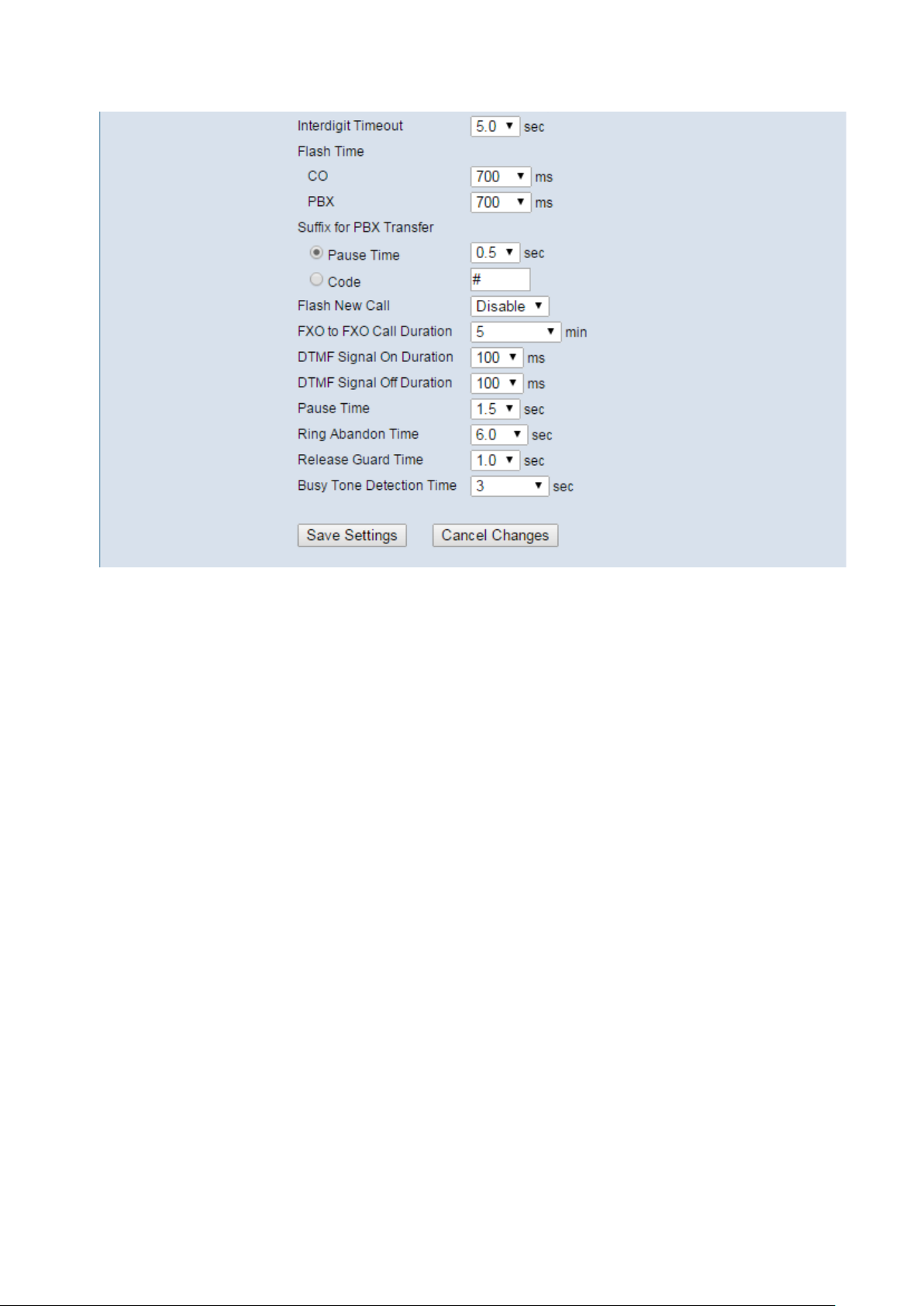
IG7600 Administration Manual
Figure 6-67. Voice – System – Transmission
Audio: It is used to set many Audio-related options. It will be applied to the all FXS and
PSTN lines.
Country: It may be used to determine not only the Caller ID detection/transmission
method but also ring/tone cadence/frequency.
RTP Packet Size: 10/20/3 0/40/50/60 ms.
Codec G.711 u-law, G.711 a-law and G. 729: IG7600 sup ports di fferent audi o priority .
You can choose “None”, “First”, “Second” and “Third”.
RFC2833 Payload: It’s used as the de faul t R F C2833 payload type when making the
outbound calls.
DTMF Type: In IG7600, there are two methods for transmitting DTMF tone. Select
RFC2833 Method, the DTMF tone will be transmitted by event packet. Select
SIP-INFO Method, the DTMF tone will be represent in SIP INFO Message.
Hold Recall Time: IG7600 provides hold recall function. When the hold recall time
expires, and IP Phone supp or ted hol d recal l funct ion, the IG will ring the IP Phone
again.
Conference Timeout: This configuration is t o limit the time of a conference call. After
the time, conference call will end.
FXS: It is used to set many FXS-related options.
Fax Support: The system supports FAX/modem tone detection with G.711 and T38
mode.
Copyright 2013 Tecom, Co. LTD. All rights reserved Page 91 of 127
Page 98

IG7600 Administration Manual
Call ID Method: The system prov ides the a bility to det ect the cal ling party identificati on
provided by PSTN li nes. I t also tr ansmi ts t he cal ling party i dentificati on to P O TS ports .
There are four choices: NONE, DTMF Before Ring, DTMF After Ring, FSK Be fore Ring,
and FSK After Ring.
Inter-digit Timeout: Its range is from 2 to 9 seconds.
FXS Hotline: Enable/Disable
FXS Hotline Number: FXS dialing number in Hotline application.
FXS Hotline Delay Ti me: At idle state, FXS lifts the handset or press the Speaker
button. A call is built to the Hotline Number either immediately or after the delay time.
FXO: It is used to set many central office line options.
Loop-break Detection Time: For every PSTN/FXO call, system provides the facility
to monitor the call status. If the remote party hangs up, the ongoing call must be
terminated. The PSTN line monitor is done by the loop-break signal or busy tone. The
value range is: Disable/100/200/…/1000 ms.
Dialing Type: It determines how t he dial ing di git s wil l be g enerate d, ei ther in D TMF or
Pulse (Rotary) signaling format.
Pulse Dialing: This s pecifies the param eter s of Pulse Dialing, y ou need to check with
your servic e provider for the correct sett ings to make the outgoing call to w ork properly .
PR Detection Time: S ome PSTN ser vice pro viders provide th e PR (Pol arity R eversal)
signal to indicate the call progress status (remote answer/hang up).
Ring Recognition Time: The timer determines the mini mum ring dur atio n recog niz ed
as a valid incoming ring on a FXO port. Shorter ring signals are ignored. The timer
range is 200ms to 600ms in 40ms increments.
Delay Ring Time: The timer is to allow the Ce ntral O ffice to s end ICL ID befor e the cal l
is answered. Once the timer expires, the programmed extensions will ring and the
ICLID number w il l be sent t o the ringing extensions. The timer r ang e i s 3 to 6 s ec onds
on 0.5 second increments.
Dial Wait Time: When the user seizes a PSTN/FXO line, the Stable Time delay is
needed to wait th e dial tone from Centr al Office. The timer r ange is 0 to 8 seconds on 1
second increments.
Inter-digit Timeout: Its range is from 2 to 9 seconds.
Flash Time: The on-off duration for sending the FLASH signal. Its range is from 90 to
3000 ms.
Flash New Call: If this item is set “Enable”, a call will be taken account of a new call
when the CO FLASH feature is used.
FXO to FXO Call Duration: The maximum calling time between two FXO lines.
DTMF Signal On/Off Duration: The on/off time duration of DTMF signals. Their
ranges are from 50 to 200 ms.
Pause Time: The pause time of alphabet “p” in the process of call dialing. The timer
range is 1 to 5 seconds on 0.5 second increments.
Copyright 2013 Tecom, Co. LTD. All rights reserved Page 92 of 127
Page 99
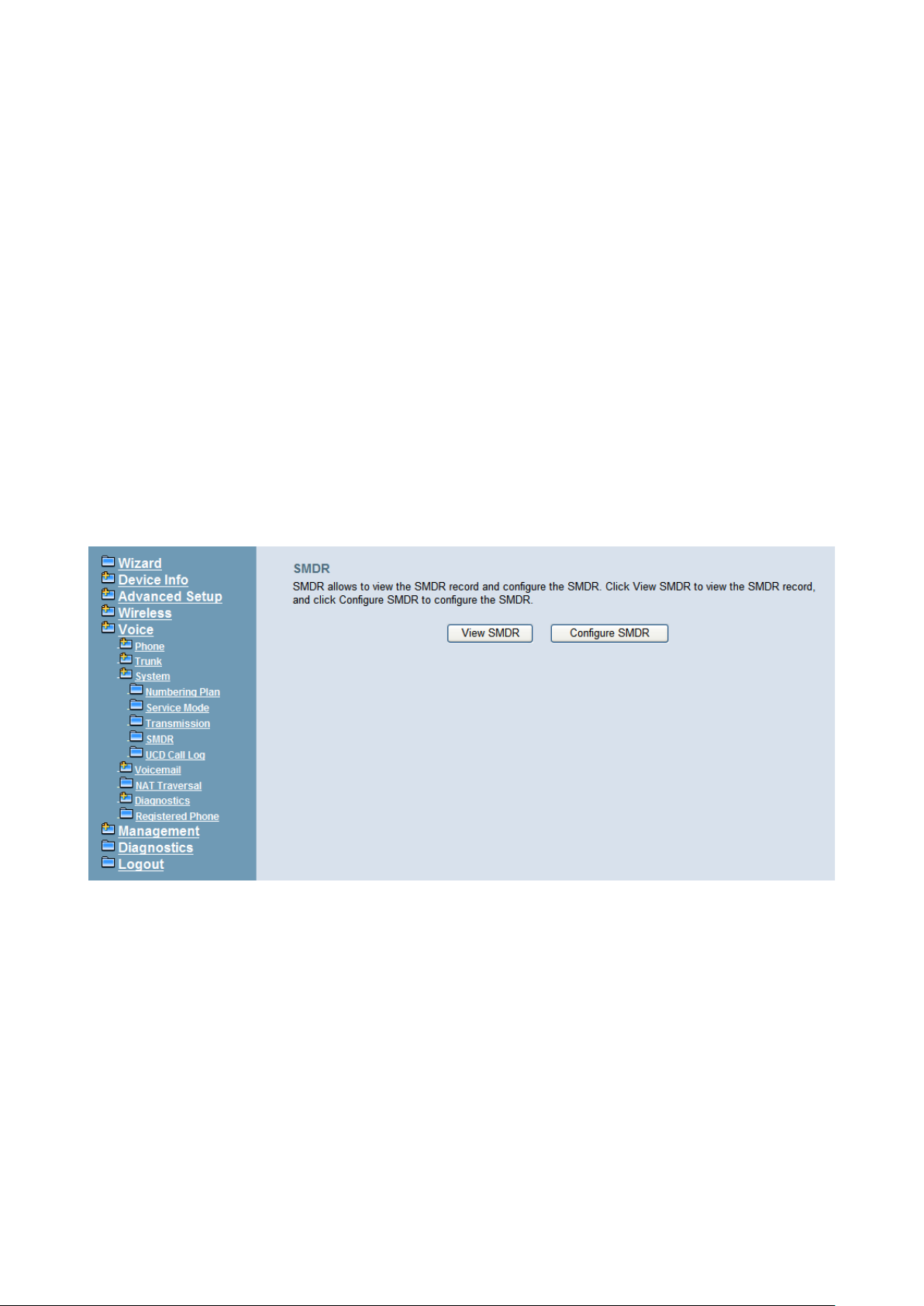
IG7600 Administration Manual
Ring Abandon Time: It specifies the maximum time between valid ring signals from
the CO/PBX. If the duration between rings exceed the Ring Abandon time, IG7600
stops ringing the destination(s) and the port returns to idle. The timer range is 1 to 10
seconds on 1 second increments.
Release Guard Time: The guard time to ignore the noise signal when releasing the
call. The timer range is 1.0 to 3.0 seconds on 0.5 second increments.
Busy Tone Detection Time: System detects the busy tone to monitor the call status.
When it reaches the detection time, system assumes the remote party hangs up. The
ongoing call will be terminated. When setting the time to “0”, the Busy Tone detection
will be disabled.
6.6.3.4 SMDR
SMDR (Station Message Detail Recording) will take down user’s dialing record. It
contains every calling period. From the log of SMDR, the administrator can charge some
fees from the user.
This page allows you to view the SMDR record and configure the SMDR. Click “View
SMDR” button to view the SMDR recor d, and c l ic k “Config ur e SM D R ” button to configure
the SMDR. (Figure 6-68, Figure 6-69, Fig ure 6-70)
Figure 6-68. Voice – System – SMDR
Copyright 2013 Tecom, Co. LTD. All rights reserved Page 93 of 127
Page 100
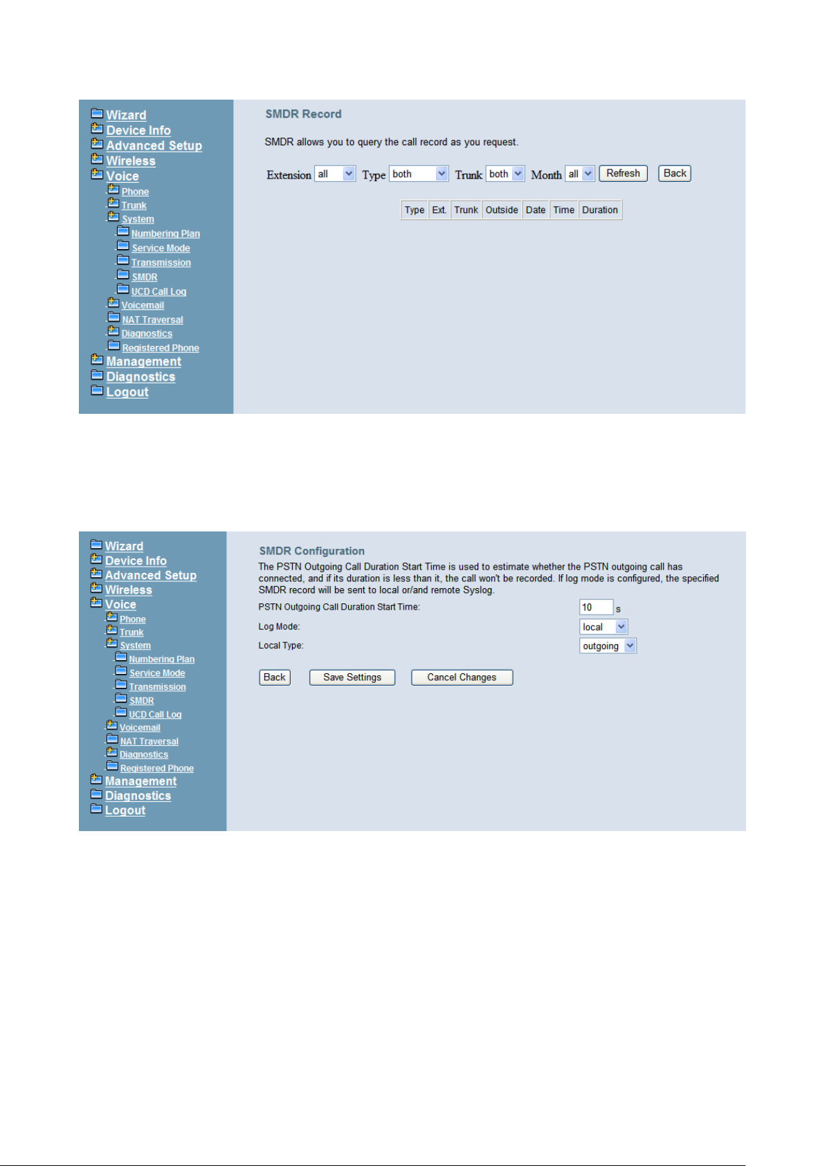
IG7600 Administration Manual
Figure 6-69. Voice – System –SMDR – View SMDR
The “PSTN Outgoing Call Duration Start Time” is used to estimate whether the PSTN
outgoing call to be recorded. If the duration is l ess than i t, the call w on't be rec orded. I f log
mode is configured, the specified SMDR record will be sent to local or/and remote log
server.
Figure 6-70. Voice – System –SMDR Configuration
6.6.3.5 UCD Call Log
This page shows the Call Log for incoming call to UCD group. (Figure 6-71)
Copyright 2013 Tecom, Co. LTD. All rights reserved Page 94 of 127
 Loading...