

Page 1
Bluetooth GPS
Page 2

Table of Contents
Trademarks 3
Welcome.....................................................4
In the Box................................................4
Getting Started............................................5
Installation and Setup.............................6
Bluetooth connection 7
PDA users 8
Laptop and Tablet PC users 10
Using the GPS for the first time ............11
Tips.......................................................13
The LED’s.............................................15
GPS Information.................. ... ... .... ... ... ... ... 17
Setup .................................................... 18
GPS Info...............................................20
GPS Technical Specifications...................24
Regulatory Notice......................................25
FCC Notice...........................................25
Modifications 26
European Union Notice.........................26
Safety Instructions ................................ 27
2
Page 3

You can find additional product and support
information at the following website:
http://www.mobilecrossing.com or contact:
Mobile Crossing
1230 Oakmead Parkway, Suite 304
Sunnyvale, CA 94085
(408) 738-8816
(800) 605-8198
Fax (408) 738-8806
email: [email protected]
© 2004 Mobile Crossing - All rights reserved
July 2004
Trademarks
Bluetooth is a trademark of Bluetooth SIG, Inc.
Velcro is a trademark of Velcro Industries B. V.
Pocket PC is a trademark of Microsoft Corporation.
All other trademarks are the property of their respective
owners. Company / product names may be trademarks
or registered trademarks of their respective holders
and are used here for identification purposes only.
3
Page 4

Welcome
Thank you for your purchase of the Mobile Crossing
®
Bluetooth
world wide to compute your position wherever you are.
It outputs standard NMEA sentences and will work with
just about every navigation program available. The unit
requires Bluetooth support on your PDA or laptop. It
has its own rechargeable battery or can receive power
from an external connection.
In the Box
The Box contains the following items
• The Bluetooth GPS.
• A CDROM containing test programs
• An AC adapter
• A DC adapter for vehicle use.
• This manual
GPS receiver. This GPS receiver will work
4
Page 5
Getting Started
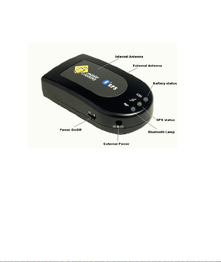
The Bluetooth GPS has a built in rechargeable battery
for totally wireless use. This battery will need to be fully
charged prior to its first use. This can be accomplished
using the supplied vehicle charger that can be plugged
into the 12V accessory (cigarette lighter) outlet in the
car or the include AC adaper.
The battery status lamp on the GPS will indicate that
the battery is being charged. This lamp will go out
5
Page 6

when the battery is fully charged. This can take up to 8
hours the first time the unit is used.
The vehicle charger includes a step down regulator to
provide 5 Volts to charge the GPS. The unit can remain
plugged into the charger while in operation which will
provide unlimited use.
Installation and Setup
A suitable location for the GPS will need to be
determined. A Velcro strip is included that can be used
to secure the unit in a vehicle while still providing
portable use when needed.
The two small strips are for the unit and should be
placed across the bottom on either side of the serial
number. The larger strip should be place in the car.
If you plan to use the unit with its internal antenna the
recommended location is up near the windshield on the
dashboard. The antenna should be facing up. The
power switch should be easily available to the driver.
If you plan to use a remote external antenna then the
unit can be installed in any location where the antenna
6
Page 7

cable will reach and the power switch can be
accessed.
It is possible to leave this unit on all of the time if a
permanent source of external power is provided.
Some accessory outlets are live all of the time and can
be used for this purpose. Many outlets turn off when
the car ignition is turned off. The unit will revert to the
battery under these conditions which will continue to
supply power for up to 8 hours for continuous service.
However, running the battery completely down over
and over will shorten the life of the battery so this mode
is not recommended in lieu of turning the unit off.
If you plan to leave the unit on be sure and provide
uninterrupted power. Do not cut the power cord and
wire it to the battery. The plug contains a regulator to
reduce the battery voltage from 12 Volts down to 5
Volts. Hooking 12 Volts directly to the unit will destroy
it.
Bluetooth connection
This unit requires a serial Bluetooth connection. While
not required, in some instances the Bluetooth interface
7
Page 8

will be more solid if the two units are bonded or paired
together. This pairing requires a passkey for access.
The Bluetooth GPS receiver supports a passkey of
‘2003’.
This number can be entered if the program asks for a
passkey.
PDA users
The unit needs serial port support from the Bluetooth
device on your PDA. If your PDA came with Bluetooth
hardware installed, you will have this service. If you
purchase a Bluetooth radio to install in your PDA be
sure that this is a feature of the product and that you
install and configure serial port support.
Pocket PC users will find the GPS located on the
outgoing serial ports defined by the Bluetoot h radio .
The Bluetooth driver should disable serial port protocol
since the Bluetooth GPS uses a simple interface and
some programs can be confused by this protocol. Palm
users will need to verify that the application they intend
to use supports Bluetooth communication.
8
Page 9

An application is needed to take advantage of the GPS
signal. The included CDROM contains a test program
called GPSInfo that can be used to verify operation on
a pocket pc. There is a description of GPSInfo on page
17 later in this manual. In most cases you will need to
configure the software to tell it where the GPS is
connected.
Some software does have the ability to search for the
GPS in automatic mode, but otherwise you will need to
determine the COM port manually. The GPSInfo
program can be used to establish the COM port
number with its Scan Com Port command.
Once the COM port number is determined it will remain
the same for all programs. The Baud rate should be set
to 4800. If the program does not offer the COM choice
then it is not compatible with Bluetooth communication.
Another way to determine the serial port number is to
use the Bluetooth access software. There are two
serial ports assigned by the Bluetooth software. T he
one assigned to outgoing is the one that will be used by
the GPS.
This unit has a built-in battery for power. The battery
will last about 8 hours on a full charge. External power
9
Page 10

is recommended for extended or unlimited use in a
vehicle. A vehicle power converter / recharger is
included.
Laptop and Tablet PC users
The Bluetooth GPS is ideal for Laptop and Tablet PC
users. It permits the GPS receiver to be placed for
optimum reception while the display is located for
convenience to the user.
If the laptop does not support Bluetooth directly, this
capability can be purchased for an available USB slot
or CF slot in the unit. For users with a PCMCIA slot a
simple CF to PCMCIA adapter can be used to permit a
CF Bluetooth radio to be used. The Bluetooth radio
should be plugged into the adapter and then the
assembly should be inserted into the unit. The labels
on both the CF card and the adapter should be pointing
up.
You will then need to install the Bluetooth driver for
Win98, 2000, or XP systems.
An application is needed to take advantage of the GPS
signals. The application will need to be told the number
of the COM port selected by the driver when it was
10
Page 11

installed. The Baud rate will need to be set to 4800.
The CDROM contains the GPS Information command
which can be used for test purposes.
This unit has a built-in battery for power. The battery
will last about 8 hours on a full charge. External power
is recommended for extended or unlimited use in a
vehicle. A vehicle power converter / recharger is
included.
Using the GPS for the first time
The very first time a GPS is used in a totally new area it
will take a little longer than usual to get a location fix.
Any GPS aware application can be used to perform
this initialization but it is best if the application has
some sort of GPS status display. Pocket PC and PC
users will find the included GPSInfo command perfect
for this task. The following steps can be used:
2. Be sure the GPS battery is fully charged.
3. Take the GPS unit and the computer outside
and select a location with a good sky view.
4. Be sure that Bluetooth communication is
enabled. The Bluetooth lamp on the GPS (Blue
on the left as shown on the next page) blinks
11
Page 12
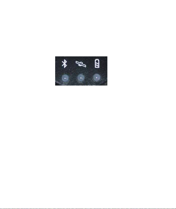
slowly when searching for a connection and
blinks quicker once a connection is
established. The effective range of the
Bluetooth connection is up to 33 feet but don’t
be surprised if it is less.
5. Run the application and select the GPS
receiver.
6. The GPS Status lamp on the receiver will light
whenever the unit is turned on. It will
immediately attempt to acquire satellite
signals.
7. Observe the display in the application to
determine if the receiver is able to
communicate to the application and is able to
see some satellites.
8. Wait! A receiver in a totally new location can
take 5 to 10 minutes to determine its first
location. In some cases it could even take
longer.
12
Page 13

9. When a location fix has been obtained the
satellite reception lamp on the receiver will
begin to flash and the application should report
that that the position has been obtained.
10. The unit is now ready and can be used as
desired.
Tips
Do not cover the internal antenna with anything. The
GPS signals are easily blocked. The Bluetooth antenna
is also in this area.
The GPS will attempt to get a lock anytime it has
power. Turn off power when inside to avoid long lock
times later due to the GPS giving up and thinking it has
to initialize itself.
Get a position lock before driving off or entering the
woods where reception may be more difficult. The GPS
can hang onto a lock easier than it can get one.
Only one program can talk to the GPS at a time. If you
have trouble connecting to the GPS, be sure that some
other program is not using it.
13
Page 14

When hiking, hold the unit horizontally with the antenna
up. If you put the unit in your pocket, be sure that the
antenna is faced out. The body blocks all GPS signals.
Some cars have a metalized sunscreen embedded in
the windshield which blocks the GPS signals. An
external antenna placed on the outside of the car will
solve this problem. Suitable locations for the antenna
include the roof, the hood, the trunk area, or the top of
the fenders. The antenna lead in wire can usually be
routed into the car via spaces between the parts on the
car such as within a door jamb or trunk lid. Most
external antennas have a magnet in their base to
permit attachment to the desired location. This GPS
unit requires an antenna with an MMCX connector and
is designed to work with 2.5 Volts.
You may want to consider the back shelf under the rear
window as a GPS location, especially if the windshield
reception is blocked.
Extreme heat and extreme cold can cause the battery
in the GPS to temporarily fail to function until a more
reasonable temperature is obtained. Do not leave the
GPS in a car where temperature extremes are
expected.
14
Page 15

The battery will discharge over time even if the unit is
off.
The LED’s
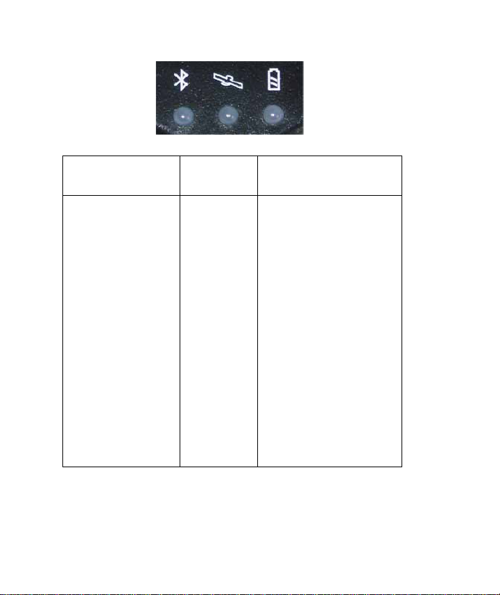
The three LED’s have special decoding as shown on
the next page.
15
Page 16
BLUETOOTH
STATUS
The Bluetooth
LED is blue and
blinks at a 4
second rate to
indicate that the
receiver is ready
but not
connected to a
Bluetooth
device. When
connected the
blink rate
increases to a 1
second rate.
GPS
STATUS
The GPS
Status
LED is
green. It
blinks
when a
GPS fix
has been
achieved.
It remains
solid
when the
unit is
searching
for a fix.
BATTERY STATUS
The Battery Status
LED is yellow or red.
It shows yellow while
charging is taking
place and turns off
when charging is
complete. On battery
power it remains off
when there is
adequate battery
power. It lights red
when the unit needs
to be recharged.
Recharge as soon
as possible.
If none of the lights will light when you turn the unit on
then the battery needs to be recharged or replaced.
16
Page 17

GPS Information
GPS Information from Globalsat Technology
Corporation is included to provide a troubleshooting
tool for any GPS problems that might be encountered.
It is available for Pocket PC and PC systems. It can be
used to reset the GPS device and provides analysis
data about a fix.
It can also be used to enable WAAS on the GPS
device. It does not report whether WAAS is in use.
WAAS is an augmentation system that can provide
increased accuracy in some situations.
It is generally not needed for road navigation, particular
when road lock is in use by the program. WAAS takes
one of the GPS satellite positions from the receiver so
you cannot use 12 satellites when WAAS is in use. The
implementation supports corrections for signal errors
but does not support WAAS ranging where the WAAS
satellite could be used to substitute for the 12th
satellite.
The GPSInfo setup command is included on the
CDROM. It can be used to install both the pc and the
pocket pc versions.
17
Page 18
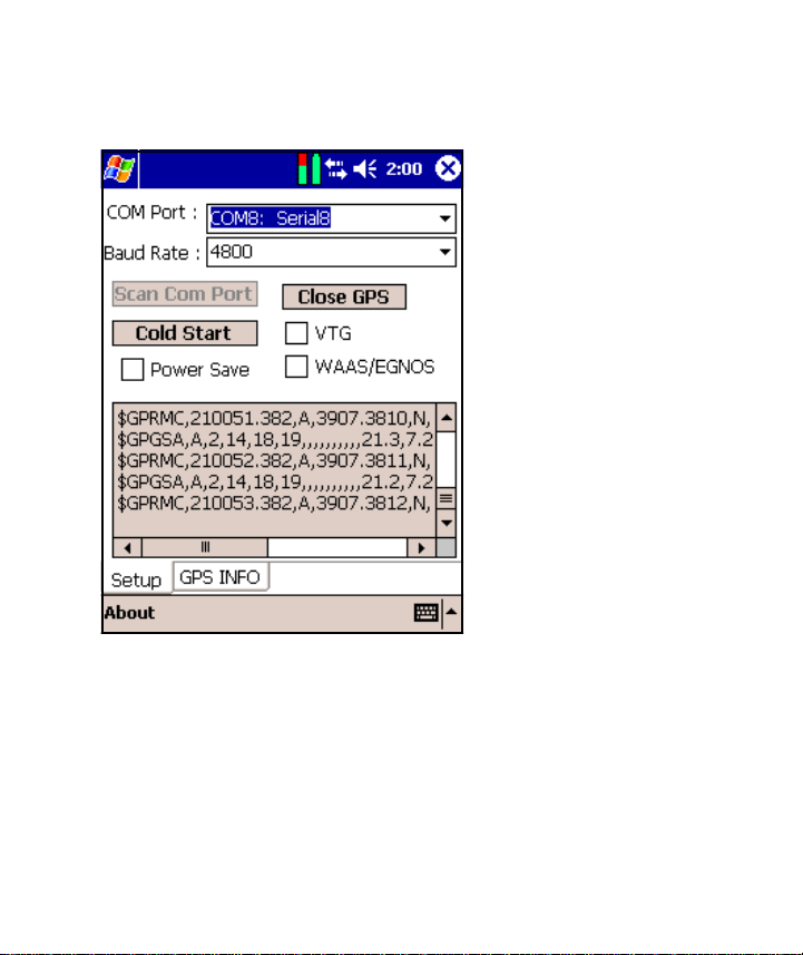
Setup
The opening
screen for GPS
Info is the place
where the
connection to
the GPS unit is
performed.
Only one
program can be
attached to a
GPS unit at any
one time. If a
connection
cannot be
established
check and
ensure that
some other software is not running or has access to
the GPS tied up.
Data will scroll up the screen while a connection is
maintained. The setup page permits some control over
the GPS itself. The commands include:
18
Page 19

• The Cold Start button will reset the GPS and
require a cold start. This could take some time so
only do this when you have a clear sky view and
are willing to wait until a new GPS fix is obtained.
• VTG checked will add this message to the NMEA
strings of data. You should not do this unless a
program specifically needs it.
• Power Save can save significant amounts of
battery power but at a cost in performance. Use
this at your own discretion, but it is not recommend
under difficult reception conditions.
The WAAS switch can be used to toggle the differential
correction capability on or off. Using WAAS ties up one
of the receiver channels and is not needed for use with
road navigation software.
The bottom of the screen shows NMEA messages as
they appear. Its primary purpose is to demonstrate that
the GPS is actively send data and the PDA can receive
it.
19
Page 20
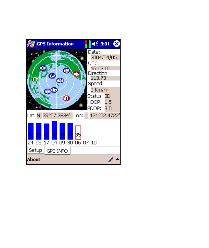
GPS Info
Tapping the
GPS Info tab
brings up the
information
display.
This screen
shows a map of
the current
satellite
positions with
the current
reception signal
strength for
each satellite
shown below the
map.
The text data about the fix surrounds the map. It is
primarily about the GPS PVT solution. All GPS
receivers compute PVT, Position, Velocity, and Time
as the full GPS solution. At the top is the GPS
computed UTC date, followed with the UTC time.
20
Page 21

GPS solutions are usually computed with respect to
Universal Time Coordinated (UTC) which used to be
called GMT (Greenwich Mean Time). The time is
computed at longitude 0 which passes through
England. California is 8 hours later than UTC (7 hours
during DST).
The other information shown includes the Velocity
(Speed and Direction) and the Position (Latitude and
Longitude) except that altitude is missing.
The rest of the text is concerned with the quality of the
fix itself. The Status reports that the GPS has a 3D
solution which means it is computing a solution in all
three axes which requires at least 4 satellites. In
addition it is showing a HDOP, Horizontal Dilution of
Position and a PDOP (Point DOP).
Dilution of Position is a unitless number that represents
how good the solution is based on the current satellite
positions. For horizontal DOP any number less than
2.0 is very good. PDOP provides a number that
includes both horizontal and vertical accuracy and 3.0
as shown above is a good number for this. This
computation is based strictly on the arrangement of
satellites as shown on the screen. Numbers above 6.0
21
Page 22

would indicate a poor arrangement that might not lead
to very accurate results.
The bar chart at the bottom of the screen shows the S/
N ratio of each satellite (signal strength) and the blue
bar indicates the satellites that are contributing to the
current solution. The numbers at the bottom of the bar
are the same numbers as the one on the map so that
the two charts can be tied together. The receiver is
getting a signal from satellite 6 but does not have the
data yet to use it as part of the solution.
By the way, the map of the earth shown on the upper
chart is bogus since the satellite view is looking up, not
down with the center of the circle representin g the
current location and North at the top. The map itself is
only a graphic and provides only misinformation but
looks nice.
GPSInfo is a powerful program that can manipulate
data using the internal SiRF binary protocol. It is
possible that some error conditions could leave the unit
in SiRF mode and not available for NMEA.
If you can make a Bluetooth connection but cannot
communicate with the unit from your GPS application,
it may be because it was locked in SiRF mode. You
22
Page 23

can try a Reset in GPS Info to clear the unit or let the
internal battery run down completely. After the battery
has completely run down the unit will return to factory
defaults which includes NMEA mode.
23
Page 24

GPS Technical Specifications
Accuracy 15 meters 2D RMS
Datum WGS 84
Hot Start 8 sec. Average
Warm Start 38 sec. Average
Cold Start 80 sec. Average
Reacquisition 100 ms. Average
GPS output data GGA, GSA, GSV, RMC,
VTG, GLL
Transfer Rate 4800, 8, n,1
Update Rate 1 Hz
Operating
Temperature
Storage
Temperature
Power 8 hours per charge
External Antenna MMCX connector
Dimensions 3.54” x 1.97” x 0.63”
All specifications are subject to change without notice.
Some specifications are dependent on the US
Government maintaining the system to meet its current
capabilities as of the printing of this document.
The included AC adapter will operate from 100 to 240
Volts AC 50 or 60 Hz. The included DC adapter will
operate from 12 to 24 Volts DC.
-20° - 60° C
-40° - 85° C
24
Page 25

Regulatory Notice
FCC Notice
This equipment has been tested and foun d to comply
the limits for a Class B digital device, pursuant to
with
Part 15 of the FCC Rules
provide reasonable protection against harmful
interference in a residential installation. This equipment
generates, uses, and can radiate radio frequency
energy, and if not installed and used in accordance
with the instructions, may cause harmful interference to
radio communications. However, there is no guarantee
that interference will not occur in a particular
installation. If this equipment does cause harmful
interference to radio or television reception (which can
be determined by turning the equipment off and on),
the user is advised to take one or more of the following
measures:
• Reorient or relocate the antenna of the unit
receiving the interference.
. These limits are designed to
• Increase the distance between the equipment and
the receiver.
25
Page 26

• Connect the equipment into an outlet on a circuit
different from that to which to receiver is
connected.
Consult your dealer or an experienced radio/TV
technician for help.
Modifications
The FCC requires the user to be notified that any
changes or modifications made to this device that are
not expressly approved by
Making modifications
to operate the equipment.
MOBILE CROSSING.
may void the reference authority
European Union Notice
Products bearing the CE marking comply with both the
EMC Directive (89/336/EEC) and the Low Voltage
Directive (73/23/EEC) issued by the Commission of the
European Community and if this product has
telecommunication functionality, the R&TTE directive
(1995/5/EC). Compliance with these directives implies
conformity to the following European Norms (in
parentheses are the equivalent international standards
and regulations):
26
Page 27

• EN55022 (CISPR 22) - Electromagnetic
Interference
• EN55024 (IEC61000-4-2, 3, 4, 5, 6, 8, 11) –
Electromagnetic Immunity
• EN61000-3-3 (IE61000-3-3) - Power Line Flicker
• EN 60950 (IEC60950) - Product Safety
Safety Instructions
This product has been tested for conformance to
international safety regulations. Like any electrical
device, however, it should be used with care. To
protect yourself from possible injury and to minimize
the risk of damage to the product, it is important that
you follow these safety instructions.
• Do not attempt to service the product yourself.
Refer servicing to qualified personnel.
• Do not use the product near water. Never spill
liquid of any kind on the product.
• Do not exceed 5 Volts on the external power input
cable.
27
Page 28

Part Code: WPM01 July 2004
28
 Loading...