

Page 1
Product Description
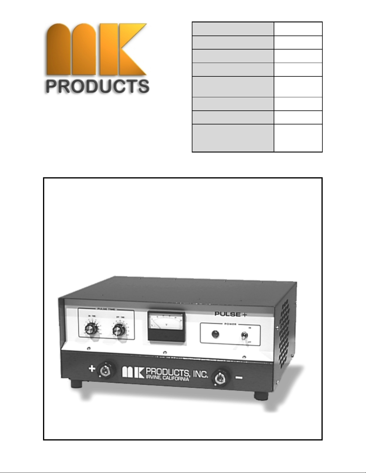
Pulse +
MK Ma n ual P a rt Numb er
MK Form Number
NWSA Form Number
Effective wi th Serial
Voltage Ratings
Printing/Rev. Date
This manual applies to
the follow ing Model
Pulse+ Add-on Pulse system
Number
Numbers
091 - 0217
PP/OM
550
0580
115
2/99 rev. A
158-001
OWNERS MANUAL
16882 ARMSTRONG AVE., IRVINE, CALIFORNIA 92606 TEL (949) 863-1234 FAX (949) 474-1428
Page 2

SAFETY CONSIDERATIONS
ELECTRIC ARC WELDING EQUIPMENT
CAUTION : READ BEFORE ATTEMPTING INSTALLATION, OPERATION
OR MAINTENANCE OF THIS EQUIPMENT
1-1 INTRODUCTION
This equipment is intended for ultimate
application by commercial/industrial
users and for operation by persons
trained and experienced in the use and
maintenance of welding equipment.
Operation should not be undertaken
without adequate training in the use of
such equipment. Training is available
from many public and private schools or
similar facilities.
Safe practices in the installation,
operation and maintenance of this
equipment requires proper training in the
art, a careful study of the information
provided with the equipment, and the
use of common sense. Rules for safe
use are generally provided by suppliers
of welding power sources, compressed
gas suppliers, and electrode suppliers.
Careful compliance with these rules will
promote safe use of this equipment.
The following Safety Rules cover some
of the more generally found situations.
READ THEM CAREFULLY. In case of
any doubt, obtain qualified help before
proceeding.
1-2 GENERAL PRECAUTIONS
A. Burn Prevention
ELECTRIC ARC WELDING PRODUCES
HIGH INTENSITY HEAT AND
ULTRAVIOLET RADIANT ENERGY
WHICH MAY CAUSE SERIOUS AND
PERMANENT EYE DAMAGE AND WHICH
MAY DAMAGE ANY EXPOSED SKIN
AREAS.
Wear helmet with safety goggles or
glasses with side shields underneath,
appropriate filter lenses or plates
(protected by clear cover glass). This
is a must for welding or cutting (and
chipping) to protect the eyes from radiant
energy and flying metal. Replace cover
glass when broken, pitted, or spattered.
Medical first aid and eye treatment. First
aid facilities and a qualified first aid
person should be available for each shift
unless medical facilities are close by for
immediate treatment of flash burns of
the eyes and skin burns.
Wear protective clothing - leather (or
asbestos) gauntlet gloves, hat, and high
safety-toe shoes. Button shirt collar and
pocket flaps, and wear cuffless trousers
to avoid entry of sparks and slag.
Avoid oily or greasy clothing. A spark
may ignite them.
Flammable hair preparations should not
be used by persons intending to weld or
cut.
Hot metal such as electrode stubs and
work pieces should never be handled
without gloves.
Ear plugs should be worn when working
on overhead or in a confined space. A
hard hat should be worn when others work
overhead.
B. T oxic Fume Prevention
WARNING: The use of this product may
result in exposure to chemicals known to
the State of California to cause cancer and
birth defects or other reproductive harm.
Adequate ventilation. Severe discomfort,
illness or death can result from fumes,
vapors, heat, or oxygen enrichment or
depletion that welding (or cutting) may
produce. Prevent them with adequate
ventilation. NEVER ventilate with oxygen.
Lead-, cadmium-, zinc-, mercury-,
beryllium-bearing and similar materials,
when welded or cut, may produce harmful
concentrations of toxic fumes. Adequate
local exhaust ventilation must be used, or
each person in the area, as well as the
operator, must wear an air-supplied
respirator. For beryllium, both must be used.
Metals coated with or containing materials
that emit toxic fumes should not be heated
unless coating is removed form the work
surface, the area is well ventilated, or the
operator wears an air-supplied respirator.
Work in a confined space only while it is
being ventilated and, if necessary, while
wearing an air-supplied respirator.
Gas leaks in a confined space should be
avoided. Leaked gas in large quantities
can change oxygen concentration
dangerously. Do not bring gas cylinders
into a confined space.
Leaving confined space, shut OFF gas
supply at source to prevent possible
accumulation of gases in the space if
downstream valves have been accidentally
opened or left open. Check to be sure that
the space is safe before reentering it.
Vapors from chlorinated solvents can be
decomposed by the heat of the arc (or
flame) to form PHOSGENE, a highly toxic
gas, and other lung and eye irritating
products. The ultraviolet (radiant) energy
of the arc can also decompose
trichloroethylene and perchloroethylene
vapors to form phosgene. DO NOT WELD
or cut where solvent vapors can be drawn
into the welding or cutting atmosphere or
where the radiant energy can penetrate to
atmospheres containing even minute
amounts of trichloroethylene or
perchloroethylene.
C. Fire and Explosion Prevention
Causes of fire and explosion are:
combustibles reached by the arc, flame,
flying sparks, hot slag, or heated material,
misuse of compressed gases and
cylinders, and short circuits.
BE AWARE THAT flying sparks or falling
slag can pass through cracks, along
pipes, through windows or doors, and
through wall or floor openings, out of
sight of the goggled operator. Sparks
can fly many feet.
To prevent fires and explosion:
Keep equipment clean and operable, free
of oil, grease, and (in electrical parts) of
metallic particles that can cause short
circuits.
If combustibles are in area, do NOT weld
or cut. Move the work if practicable, to
an area free of combustibles. Avoid
paint spray rooms, dip tanks, storage
areas, ventilators. If the work cannot
be moved, move combustibles at least
35 feet away, out of reach of sparks
and heat; or protect against ignition with
suitable and snug-fitting, fire-resistant
covers or shields.
Walls touching combustibles on opposite
sides should not be welded on (or cut).
Walls, ceilings, and floor near work
should be protected by heat-resistant
covers or shields.
Fire watcher must be standing by with
suitable fire extinguishing equipment
during and for some time after welding
or cutting if:
1. Appreciable combustibles (including
building construction) are within 35 feet.
2. Appreciable combustibles are further
than 35 feet, but can be ignited by sparks.
3. Openings (concealed or visible) in
floors or walls within 35 feet may expose
combustibles to sparks.
4. Combustibles adjacent to walls,
ceilings, roofs, or metal partitions can
be ignited by radiant or conducted heat.
Hot work permit should be obtained
before operation to ensure supervisor’s
approval that adequate precautions have
been taken.
After work is done, check that area is
free of sparks, glowing embers, and
flames.
An empty container that held
combustibles, or that can produce
flammable or toxic vapors when heated,
must never be welded on or cut, unless
container has first been cleaned in
accordance with industry standards.
This includes: a thorough steam or
caustic cleaning (or a solvent of water
washing, depending on the
combustible’s solubility), followed by
Pulse+ Owner's Manual
Page 3

purging and inerting with nitrogen or
carbon dioxide, and using protective
equipment.
Water-filling just below working level may
substitute for inerting.
A container with unknown contents
should be cleaned (see paragraph
above). Do NOT depend on sense of
smell or sight to determine if it is safe to
weld or cut.
Hollow castings or containers must be
vented before welding or cutting. They
can explode.
Explosive atmospheres. NEVER weld
or cut where the air may contain
flammable dust, gas, or liquid vapors
(such as gasoline).
D. Compressed Gas Equipment
The safe handling of compressed gas
equipment is detailed in numerous
industry publications. The following
general rules cover many of the most
common situations.
1. Pressure Regulators
Regulator relief valve is designed to
protect only the regulator from
overpressure; it is not intended to
protect any downstream equipment.
Provide such protection with one or more
relief devices.
Never connect a regulator to a cylinder
containing gas other than that for which
the regulator was designed.
Remove faulty regulator from service
immediately for repair (first close cylinder
valve). The following symptoms indicate
a faulty regulator:
Leaks - if gas leaks externally.
Excessive Creep - if delivery pressure
continues to rise with downstream valve
closed.
Faulty Gauge - if gauge pointer does not
move off stop pin when pressurized,
nor returns to stop pin after pressure
release.
Repair. Do NOT attempt repair. Send
faulty regulators for repair to
manufacturer’s designated repair center,
where special techniques and tools are
used by trained personnel.
2. Cylinders
Cylinders must be handled carefully to
prevent leaks and damage to their walls,
valves, or safety devices:
Avoid electrical circuit contact with
cylinders including third rails, electrical
wires, or welding circuits. They can
produced short circuit arcs that may lead
to a serious accident. (See 1-3C)
ICC or DOT marking must be on each
cylinder. It is an assurance of safety
when the cylinder is properly handled.
Identifying gas content. Use only
cylinders with name of gas marked on
them; do not rely on color to identify gas
content. Notify supplier if unmarked.
NEVER DEFACE or alter name, number ,
or other markings on a cylinder . It is illegal
and hazardous.
Empties: Keep valves closed, replace caps
securely; mark MT; keep them separate
from FULLS, and return promptly.
Prohibited use. Never use a cylinder or its
contents for other than its intended use,
NEVER as a support or roller.
Locate or secure cylinders so they cannot
be knocked over.
Passageways and work areas. Keep
cylinders clear of areas where they may
be stuck.
Transporting cylinders. With a crane, use
a secure support such as a platform or
cradle. Do NOT lift cylinders off the ground
by their valves or caps, or by chains, slings,
or magnets.
Do NOT expose cylinders to excessive
heat, sparks, slag, and flame, etc. that may
cause rupture. Do not allow contents to
exceed 55 degrees C (130 degrees F .) Cool
with water spray where such exposure
exists.
Protect cylinders, particularly valves from
bumps, falls, falling objects, and weather.
Replace caps securely when moving
cylinders.
Stuck valve. Do NOT use a hammer or
wrench to open a cylinder valve that
cannot be opened by hand. Notify your
supplier.
Mixing gases. NEVER try to mix any gases
in a cylinder.
NEVER refill any cylinder .
Cylinder fittings should never be modified
or exchanged.
3. Hose
Prohibited use. Never use hose other than
that designed for the specified gas. A
general hose identification rule is: red for
fuel gas, green for oxygen, and black for
inert gases.
Use ferrules or clamps designed for the
hose (not ordinary wire or other substitute)
as a binding to connect hoses to fittings.
No copper tubing splices. Use only
standard brass fittings to splice hose.
Avoid long runs to prevent kinks and abuse.
Suspend hose off ground to keep it from
being run over, stepped on, or otherwise
damaged.
Coil excess hose to prevent kinks and
tangles.
Protect hose from damage by sharp edges,
and by sparks, slag, and open flame.
Examine hose regularly for leaks, wear,
and loose connections. Immerse
pressured hose in water; bubbles indicate
leaks
Repair leaky or worn hose by cutting area
out and splicing. Do NOT use tape.
4. Proper Connections
Clean cylinder valve outlet of impurities that
may clog orifices and damage seats before
connecting regulator. Except for hydrogen,
crack valve momentarily, pointing outlet
away from people and sources of
ignition. Wipe with a clean, lintless cloth.
Match regulator to cylinder. Before
connecting, check that the regulator label
and cylinder marking agree, and that the
regulator inlet and cylinder outlet match.
NEVER Connect a regulator designed for
a particular gas or gases to a cylinder
containing any other gas.
Tighten connections. When assembling
threaded connections, clean and smooth
seats where necessary. Tighten. If
connection leaks, disassemble, clean,
and retighten, using properly fitting
wrench.
Adapters. Use a CGA adapter (available
from your supplier) between cylinder
and regulator, if one is required. Use
two wrenches to tighten adapter marked
RIGHT and LEFT HAND threads.
Regulator outlet (or hose) connections
may be identified by right hand threads
for oxygen and left hand threads (with
grooved hex on nut or shank) for fuel
gas.
5. Pressurizing Steps:
Drain regulator of residual gas through
suitable vent before opening cylinder (or
manifold valve) by turning adjusting
screw in (clockwise). Draining prevents
excessive compression heat at high
pressure seat by allowing seat to open
on pressurization. Leave adjusting
screw engaged slightly on single-stage
regulators.
Stand to side of regulator while opening
cylinder valve.
Open cylinder valve slowly so that
regulator pressure increases slowly.
When gauge is pressurized (gauge
reaches regulator maximum) leave
cylinder valve in following position: for
oxygen and inert gases, open fully to
seal stem against possible leak; for fuel
gas, open to less than one turn to permit
quick emergency shut-off.
Use pressure charts (available from your
supplier) for safe and efficient
recommended pressure settings on
regulators.
Check for leaks on first pressurization
and regularly thereafter. Brush with
soap solution. Bubbles indicate leaks.
Clean off soapy water after test; dried
soap is combustible.
E. User Responsibilities
Follow all Safety Rules.
Remove leaky or defective equipment
from service immediately for repair. Read
and follow user manual instructions.
F . Leaving Equipment Unattended
Close gas supply at source and drain
gas.
G. Rope Staging-Support
Rope staging-support should not be used
for welding or cutting operation; rope
may burn.
Pulse+ Owner's Manual
Page 4

1-3 ARC WELDING
Comply with precautions in 1-1, 1-2, and
this section. Arc Welding, properly done,
is a safe process, but a careless
operator invites trouble. The equipment
carries high currents at significant
voltages. The arc is very bright and hot.
Sparks fly, fumes rise, ultraviolet and
infrared energy radiates, weldments are
hot, and compressed gases may be
used. The wise operator avoids
unnecessary risks and protects himself
and others from accidents.
A. Burn Protection
Comply with precautions in 1-2.
The welding arc is intense and visibly
bright. Its radiation can damage eyes,
penetrate lightweight clothing, reflect
from light-colored surfaces, and burn
the skin and eyes. Skin burns resemble
acute sunburn; those from gas-shielded
arcs are more severe and painful. DON’T
GET BURNED; COMPLY WITH
PRECAUTIONS.
1. Protective Clothing
Wear long-sleeve clothing in addition to
gloves, hat, and shoes. As necessary,
use additional protective clothing such
as leather jacket or sleeves, flameproof
apron, and fire-resistant leggings. Avoid
outer garments of untreated cotton.
Bare skin protection. Wear dark,
substantial clothing. Button collar to
protect chest and neck, and button
pockets to prevent entry of sparks.
2. Eye and Head Protection
Protect eyes from exposure to arc. Eyes
may be damaged by radiant energy
when exposed to the electric arc, even
when not looking in the direction of the
arc. Never look at an electric arc without
protection.
Welding helmet or shield containing a filter
plate shade no. 12 or denser must be
used when welding. Place over face
before striking arc.
Protect filter plate with a clear cover
plate.
Cracked or broken helmet or shield should
NOT be worn; radiation can be passed
through to cause burns.
Cracked, broken, or loose filter plates
must be replaced IMMEDIA TELY . Replace
clear cover plate when broken, pitted,
or spattered.
Flash goggles with side shields MUST
be worn under the helmet to give some
protection to the eyes should the helmet
not be lowered over the face before an
arc is struck. Looking at an arc
momentarily with unprotected eyes
(particularly a high intensity gas-shielded
arc) can cause a retinal burn that may
leave a permanent dark area in the field
of vision.
3. Protection of Nearby Personnel
Enclose the welding area. For production
welding, a separate room or enclosed
bay is best. In open areas, surround the
operation with low-reflective,
noncombustible screens or panels. Allow
for free air circulation, particularly at floor
level.
Viewing the weld. Provide face shields for
all persons who will be looking directly at
the weld.
Others working in area. See that all persons
are wearing flash goggles.
Before starting to weld, make sure that
screen flaps or bay doors are closed.
B. Toxic Fume Prevention
Comply with precautions in 1-2B.
Generator engine exhaust must be vented
to the outside air. Carbon monoxide can
kill.
C. Fire and Explosion Prevention
Comply with precautions in 1-2C.
Equipment’s rated capacity . Do not overload
arc welding equipment. It may overheat
cables and cause a fire.
Loose cable connections may overheat or
flash and cause afire.
Never strike an arc on a cylinder or other
pressure vessel. It creates a brittle area
that can cause a violent rupture or lead to
such a rupture later under rough handling.
D. Compressed Gas Equipment
Comply with precautions in 1-2D.
E. Shock Prevention
Exposed electrically hot conductors or other
bare metal in the welding circuit, or in
ungrounded, electrically-HOT equipment
can fatally shock a person whose body
becomes a conductor. DO NOT STAND,
SIT, LIE, LEAN ON, OR TOUCH a wet
surface when welding without suitable
protection.
To protect against shock:
Keep body and clothing dry . Never work in
damp area without adequate insulation
against electrical shock. Stay on a dry
duckboard, or rubber mat when dampness
or sweat cannot be avoided. Sweat, sea
water, or moisture between body and an
electrically HOT part - or grounded metal reduces the body surface electrical
resistance, enabling dangerous and
possibly lethal currents to flow through the
body.
1. Grounding the Equipment
When installing, connect the frames of each
unit such as welding power source,
control, work table, and water circulator to
the building ground. Conductors must be
adequate to carry ground currents safely.
Equipment made electrically HOT by stray
currents may shock, possibly fatally. Do
NOT GROUND to electrical conduit, or to a
pipe carrying ANY gas or a flammable liquid
such as oil or fuel.
Three-phase connection. Check phase
requirement of equipment before installing.
If only three-phase power is available,
connect single-phase equipment to only
two wires of the three-phase line. Do NOT
connect the equipment ground lead to
the third (live) wire, or the equipment
will become electrically HOT - a
dangerous condition that can shock,
possibly fatally.
Before welding, check ground for
continuity. Be sure conductors are
touching bare metal of equipment frames
at connections.
If a line cord with a ground lead is
provided with the equipment for
connection to a switch box, connect the
ground lead to the grounded switch box.
If a three-prong plug is added for
connection to a grounded mating
receptacle, the ground lead must be
connected to the ground prong only. If
the line cord comes with a three-prong
plug, connect to a grounded mating
receptacle. Never remove the ground
prong from a plug, or use a plug with a
broken ground prong.
2. Connectors
Fully insulated lock-type connectors
should be used to join welding cable
lengths.
3. Cables
Frequently inspect cables for wear,
cracks, and damage. IMMEDIATELY
REPLACE those with excessively worn
or damaged insulation to avoid possibly
lethal shock from bared cable. Cables
with damaged areas may be taped to
give resistance equivalent to original
cable.
Keep cable dry, free of oil and grease,
and protected from hot metal and sparks.
4. Terminals & Other Exposed Parts
Terminals and other exposed parts of
electrical units should have insulating
covers secured before operation.
5. Electrode Wire
Electrode wire becomes electrically HOT
when the power switch of gas metalarc welding equipment is ON and welding
gun trigger is pressed. Keep hands and
body clear of wire and other HOT parts.
6. Safety Devices
Safety devices such as interlocks and
circuit breakers should not be
disconnected or shunted out.
Before installation, inspection, or service
of equipment, shut OFF all power, and
remove line fuses (or lock or red-tag
switches) to prevent accidental turning
ON of power. Disconnect all cables from
welding power source, and pull all 115
volts line-cord plugs.
Do not open power circuit or change
polarity while welding. If, in an
emergency, it must be disconnected,
guard against shock burns or flash from
switch arcing.
Leaving equipment unattended. Always
shut OFF, and disconnect all power to
equipment.
Power disconnect switch must be
available near the welding power
source.
Pulse+ Owner's Manual
Page 5

MK Products, Inc.
Printed in the U.S.A.
Page 6

Table of Contents
INTRODUCTION....................................................................... 2
Section 1 SPECIFICATIONS .................................................. 9
Section 2 INSTALLATION INSTRUCTIONS ........................... 10
2.1 LOCATION .....................................................................10
2.2 AUXILIARY POWER REQUIREMENTS ................................ 10
2.3 WELD CABLE CONNECTIONS ........................................... 10
Section 3 CABLE CONNECTIONS......................................... 11
Section 4 OPERATION ........................................................ 12
4.1 POWER SWITCH..............................................................1 2
4.2 VOLTMETER.................................................................... 12
4.3 PULSE OPERATION ......................................................... 12
Section 5 PARAMETER SET-UP ........................................... 15
5.1 Peak Level .......................................................................15
5.2 “ON” Time ...................................................................... 15
5.3 "OFF” Time ..................................................................... 15
Section 6 TROUBLE SHOOTING .......................................... 17
6.1 TESTING THE CURRENT SWITCH .................................... 18
6.2 TESTING THE PC BOARD ................................................ 18
6.3 TESTING THE THERMOSTAT ........................................... 18
6.4 TESTING CR1 AND R1..................................................... 18
Section 7 PARTS LIST - PULSE+ WITH METER .................... 19
Pulse+ Owner's Manual Page 6
Page 7

THIS P AGE INTENTIONALLY BLANK
Pulse+ Owner's Manual Page 7
Page 8

INTRODUCTION
MK Products’ patented Pulse+ is a transistorized pulse-generating
attachment which converts a conventional constant voltage (CV) D.C.
power supply into a variable pulsed arc welding machine.
The Pulse+ is exceptionally simple to operate and may be used with any
conventional constant voltage (CV) machine, up to 60 open circuit volts
and 300 amperes continuous current output. It provides pulse rates
continuously variable from 500 pulse per second, down to approximately
30 pulses per second. This of course, includes the frequencies of 60 and
120 pulse per second, available from thyristor supplies operating at line
frequencies.
The power supply voltage control set the peak voltage, and the background
level is a fixed value by design. The “On time” control is used to adjust the
length of the pulse during metal transfer and can be used to apply more
heat to the weld. The “Off time” control regulates how close the “on”
pulses are together, which can reduce the amount of heat into the weld.
The Pulsed-arc process is a transfer process wherein spray transfer occurs
at regular intervals rather than at random intervals. The welding current
rapidly switches from high pulsed current to low background current level.
The background current sustains the arc, while each pulse supplies just
enough power to free one droplet from the wire tip. In the time between
pulses, the welding current is reduced, and no metal transfer occurs.
Pulsed spray uses a lower average current than in regular spray transfer.
This lower average current makes it possible to weld out of position. By
using a lower average, less heat is put into the metal, causing less distortion of the material being welded. Thin metal sections may also be welded
more easily with pulsed spray, and it creates very little metal spatter. In
addition, the pulse agitation aids in cleaning action and outgasing, which
reduces porosity.
The pulsed spray transfer method can use larger diameter electrode wire
and still produce a small weld. This is a great advantage, because larger
diameter electrode are less expensive than smaller ones. Also, nonferrous
wire of a larger diameter can be fed through the wire feeder much easier
without risk of bending or jamming. This also allows using one size wire for
a variety of jobs using many different thicknesses of metal and joint
designs with just one setup in the wire feeder!
At MK Products, we stand behind every product manufactured and ensure
that it is free from defects and will perform to the specification contained in this manual. If for ANY reason you are not completely satisfied
with your purchase, we will make every effort to repair, replace, or refund
your purchase.
That is my guarantee.
Douglas M Kensrue
President
MK Products
Pulse+ Owner's Manual Page 8
Page 9

Section 1 SPECIFICATIONS
PRIMARY POWER INPUT - 1 15V AC 50-60 Hz 1 Ampere
WELDING POWER INPUT - D.C. 10-60 Volts 0 to 300 Amperes
WELDING POWER OUTPUT - D.C. 10-58 Volts 0 to 300 Amperes
PULSE CAP ACITY - Pulsed “On” Period - 1 to 10 milliseconds
SI Z E - 18”W x &-3/4”H x 14”L
WE IGHT - 31 lbs.
ENVIRONMENT - 20 to 105 degrees F , 90% humidity without
AREA REQUIRED - Access required both front and back for
- Pulse “Off” Period - 1 to 20 milliseconds
- Pulse Frequency V ariable from 30 - 500 pps
condensation 0 - 10,000 feet elevation.
Units may be stacked vertically up to four
high.
connectors and four inches on sides for air
circulation.
PULSE OUTPUT VOL T AGE - Equals connected power supply output
voltage, minus approximately a two volt
drop.
BACKGROUND LEVEL - Is automatically adjusted depending on
connected power supply output voltage, wire
characteristics, wire feed rate, and other
welding characteristics. It will typically be
30 to 130 amperes.
CONTROLS -
On/Off Switch
Pulse “On” Time - Controls high current
density pulse duration which should be
adjusted to achieve welding metal droplet
formation, detachment, and axial transfer
to work.
- Pulse “Off” Time - Controls the average
welding heat (energy) and should be ad
justed to be consistent with wire feed speed
used.
- Voltmeter - Reads average voltage while
welding.
Pulse+ Owner's Manual Page 9
Page 10

Section 2 INSTALLATION INSTRUCTIONS
2.1 LOCATION
The Pulse+ should be located to provide adequate ventilation for cooling. There
should be a minimum of four inches on each side.
CAUTION: Overheating of unit can cause possible damage
to internal components.
There should be access to both the front and rear of the unit to allow quick
disconnection of welding cables for applications not requiring pulse capabilities. For standard welding, the connectors can be locked together , thus
removing the Pulse+ from the circuit.
CAUTION: DO NOT operate the Pulse+ in the OFF position.
Doing so will cause damage to internal parts.
2.2 AUXILIARY POWER REQUIREMENTS
The Pulse+ is designed to operate on 220 volt 1 Ampere 50-60 Hz circuit. This
circuit could be a wall outlet or from an outlet on the power supply , if one is
provided.
2.3 WELD CABLE CONNECTIONS
Provided with the Pulse+ are two Dinse 400 Amp male weld cable connectors
(P/N 153-0755) and two Dinse 400 Amp female weld cable connectors (P/N
153-0813).
Select adequate size welding cable for the anticipated maximum weld current.
Keep the cables as short as possible and as close together as possible.
Excessive cable length adds resistance which may reduce the output.
To install the connectors, use Fig. 1 for proper part orientation.
NOTE: Place the connector boot over the cable before cutting back the insulation.
This will keep the copper strands from becoming frayed.
CONNECTOR P ART ORIENTA TION - Fig. 1
Pulse+ Owner's Manual Page 10
Page 11

Section 3 CABLE CONNECTIONS
Connect the Pulse+ in series with the power source as show in Figure 2.
Connect between any conventional D.C. constant voltage power source (with a maximum output
voltage of 60 volts) and the wire feeder. Plug Pulse+ into a 115 V . AC outlet.
Pulse+ Owner's Manual Page 11
Page 12

Section 4 OPERATION
CAUTION: DO NOT ATTEMPT TO WELD WITH THE PULSE+ TURNED OFF
For non-pulsed operation, the connectors can be locked together, thus removing
4.1 POWER SWITCH
Placing the power switch in the On position energizes the fan and control
circuitry . The red indicator lamp should be on at this time.
CAUTION: If the fan does not operate when the power switch is in the On position,
DO NOT attempt to weld. Without proper air flow, unit can overheat and cause
4.2 VOLTMETER
The voltmeter on the front of the Pulse+ will read average voltage during
welding. Average amperage can be read off of the power supply amp meter .
4.3 PULSE OPERATION
In pulsed spray welding, the current is varied from the background level to a
peak level. The background level is well below the transition current, while the
peak level is well into the spray arc region, Figure 3. During the peak level,
one droplet is transferred to the work. The current then drops to the background level, which allows the puddle to cool, at which time no metal is
transferred.
the Pulse+ from the circuit.
damage to internal parts.
Pulse+ Owner's Manual Page 12
Page 13

4.3.1. Peak Level
The peak level is set by the voltage control at the power supply . Because the
peak level must be well into the spray arc region, it must be set substantially
higher than non-pulsed operation (typically 30-40 volts).
4.3.2. Background Level
The background level (typically 30 to 130 amps) is the result of the fixed design
values in the Pulse+, together with the power supply input voltage, wire feed
rate, and other parameters.
4.3.3. “On Time”
T o obtain the one drop transfer during the peak level, the “On” time must be
varied, depending on the wire diameter . As the wire size is increased, so must
the “On” time be increased to burn off the larger size wire, Figure 4.
The “On” time is variable from 1 to 10 Ms.
4.3.4. “Off Time”
With the “On” time set to provide a smooth transfer, the “Of f” time is used to
control the amount of heat. Decreasing the “Off” time moves the pulses closer
together (more heat), while increasing the “Off” time moves the pulses further
apart (less heat), Figure 5.
The “Off” time is variable from 1 to 20 ms.
Pulse+ Owner's Manual Page 13
Page 14

4.3.5. Pulse Frequency
The pulse frequency is determined by adding the “On” time and the “Off” time
and dividing it into 1000. Pulse frequency is measured in pulses per second
(PPS). For example:
3 ms on and 5 ms off equals 1000/3+5 = 1000/8 = 125 pps
Pulse+ Owner's Manual Page 14
Page 15

Section 5 PARAMETER SET-UP
5.1 Peak Level
The voltage control on the power supply is used to set the peak level. The
melting temperature of the filler wire used determines at what point the voltage
should be set. For example, 4043 aluminum may require as little as 30 peak
welding volts, whereas steel and stainless may require 35-38 peak welding
volts, Figure 7. When trying to weld thin material the peak voltage should be
kept as low as possible without losing the spray transfer.
5.2 “ON” Time
The “On” time dial is used to obtain a smooth transfer . Start with an “On” time
of 2 ms, and adjust until the correct transfer is achieved.
5.3 “OFF” Time
Start with an “Off” time of 6 ms. If the weld is too cold, decrease the “Off” time.
If the weld is too hot, increase the “Off” time. Remember that the wire feed
speed must also be increased and decreased accordingly
NOTE: The required open circuit voltage (OCV) may vary from one power supply to
another, depending on the slope of the power supply. Sample parameters can be
found on the nest page.
Pulse+ Owner's Manual Page 15
Page 16

SAMPLE WELDING PARAMETERS
WIRE
SIZE
WIRE
TYPE
WIRE
IPM
WELDING
VOLTS
AVERAGE
VOLTS
WELD
AMPS
.030 4043 228 29.5 16.8 52
.035 4043 200 29.5 17.9 67
.035 4043 220 31 18.7 89
3/64 4043 180 33 19.1 108
3/64 4043 214 33 20.3 117
1/16 4043 15 36 22.5 187
.030 5356 308 30 20 59
.035 5356 360 30 18 80
.035 5356 390 30 17.5 88
3/64 5356 250 34 19.5 110
3/64 5356 300 35 20 125
PULSEONPULSE
OFF
1 10
2 11
2 8
3 8
3 5
4 2
1 6
2 10
2 8
3 8
3 5
PLATE
THICKNESS
BASE
METAL
.060 6061 Argon
.090 6061 Argon
1/8 6061 Argon
1/8 6061 Argon
1/4 6061 Argon
3/8 6061 Argon
.060 6061 Argon
.090 6061 Argon
1/8 6061 Argon
1/8 6061 Argon
1/4 6061 Argon
GAS
USED
1/16 5356 260 36 23.5 190
.030 E70S-3 190 33 18.5 65
.035 E70S-3 211 34 19.8 99
.045 E70S-3 150 36 21.8 133
.030 308L 279 34 20.3 78
.035 308L 268 34 20.3 105
.045 308L 145 34 20.9 123
4 2
1.5 15
2 9
3 5
2 8
2.75 6
3 5
3/8 6061 Argon
.050 Steel 98-2
.060 Steel 98-2
3/16 Steel 98-2
.060 S/S 98-2
.080 S/S 98-2
1/8 S/S 98-2
Pulse+ Owner's Manual Page 16
Page 17

Section 6 TROUBLE SHOOTING
SOME F ACTORS TO CONSIDER:
The Pulse+ can only
be sure the CV power supply is operating properly without the Pulse+.
The power supply sets the peak level and, therefore, must be set substantially
higher than non-pulsed operation.
When an arc is initiated, the Pulse+ is always in the pulse “on” mode to
provide maximum current to initiate the arc. After welding current is flowing, a
current switch is utilized to start the pulse timer.
If there appears to be too little output to weld with, be sure the pulse “on” is at
the proper value (or increase it) and that the pulse “off” is not excessive.
Be sure there is a good ground connection to the work and a good cable
connection to the Wire Feeder .
reduce the power supply output voltage and current, so
TROUBLE SHOOTING PROCEDURE
Trouble Cause Remedy/Explanati on
Have weld ing output
but no pulse
Pilot lamp works , Fan
works , No we ld o utput
Completely Inoperative Open line fuse (F1) Replace fuse 2A 250V
Current switch failure or bad
PC board
J2 connector disconnected
from PC board
Thermostat open Check Thermostat for continuity
Po we r S upp ly voltag e to o low Increas e sup p ly voltag e
Open CR1 or R1, Bad PC
board
The current switch, connected to J4, is
located on the negati ve buss bar next to the
capactitor bank. Disconnect J4 and short
between pins. If the unit now pulses,
replace the current switch. If it does not
pulse, check PC board.
Replace J2 on board
Disconnect 115 vac. With a ohm-meter
check resistance between input + and
output + terminals. Should read 5 ohms. If
open, check CR1 and R1 separate. If OK,
check PC board.
Defective power swi tch (S1) Replace switch
Improp e r li ne vo lta ge Che ck li ne vo lta g e for 115 vac
Pulse+ Owner's Manual Page 17
Page 18

6.1 TESTING THE CURRENT SWITCH
When current flows through the buss bar, it creates a magnetic field. This
magnetic field causes the current switch, which is normally open, to close and
turn on the pulse timer circuit. To test, remove the current switch from the unit.
Using an ohm meter on Rx1 scale, check to see that the switch is open,
indicating no continuity . Using a common magnet, move it to within one to
one-half inch from the current switch while watching the ohm meter . As the
magnet nears the current switch, it should close, and continuity should be read
on the meter .
6.2 TESTING THE PC BOARD
An oscilloscope is required to test the PC board. Set the oscilloscope second/div to 2 ms and the volts/div to 5V . Place the negative lead on pin 7 of the
transformer and the positive lead to connector J2 pin 3. The current switch
must be closed so jumper between pins 1 and 2 on the J4 connector, or place
a magnet next to the current switch, if you know it works correctly. Turn the
Pulse+ on. A square wave should appear on the oscilloscope. The “on” and
“off” time controls should vary the wave form on the oscilloscope. A bad
thermostat will also prevent the PC board from operating.
6.3 TESTING THE THERMOSTAT
The thermostat is located on the back of the heat sink and is connected to J5.
It is normally closed and, if the fan malfunctions or if the duty cycle is exceeded, the thermostat will open at 180 degrees F and shut down the unit. To
test, use an ohm meter to check for continuity across the thermostat leads.
6.4 TESTING CR1 AND R1
CR1 is the main diode coming off the + input and mounts to the heat sink. R1
is the power resistor inside the heat sink. If either is open, the Pulse+ will not
operate. To test, place an ohm meter on DC+ in the Rx1 scale. Attach the
positive lead to the + input and the negative lead to the + output. The meter
should read from 4 to 5 ohms. If open, check CR1 and R1 separately .
NOTE: The following conditions were used through-out the above test.
WELDING GAS: Aluminum (Argon), Steel & Stainless (98% Argon -
2% Oxygen)
POWER SUPPLY: Flat Slope C.V.
WELD PO SITION: Flat
WELD TYPE: Fillet
Pulse+ Owner's Manual Page 18
Page 19

Section 7 PARTS LIST - PULSE+ WITH METER
ITEM PART NO. DESCRIPTION
1 003-0661 Assy. - Top & Bottom Heat Sinks
2 003-0666 Assy. - Cover
3 003-0481 PCB Ctrl Mod.
4 325-0225 10-32 x 3/8 Pan. HD. Scr
5 333-0007 #10 Lock Washer
6 341-0008 #10-32 Hex Nut
7 328-0229 10-32 x 1/2 Soc. Hd. Scr.
8 331-0044 #10 Flat Washer
9 333-0045 #10 Lock Washer
10 435-0821 Connector Strip
11 104-0051 Capacitor - 25,000 mf
12 151-0001 Fuse 2 Amp.
13 152-0058 Fuse Holder
14 153-0809 Connector - Male
15 315-0696 Strain Relief
16 844-0019 A.C. Power Cable 6ft bare leads
17 328-0236 8 - 32 x 3/8 Sosc. HD. cr.
18 333-0006 #8 Lock Washer
19 843-0272 Cable Assy
20 003-0780 Sensor Assembly
21 333-0024 #8 Lock Washer
22 327-0073 8 - 32 x 1/4 Self Tapping Scr.
23 435-0830 Bus Bar
24 325-0167 8 - 32 x 3/8 Pan. Hd. Scr.
25 333-0024 #8 Lock Washer
26 153-0754 Connector - Female
27 329-0221 M-10 Hx. Hd. Scr. (Metric)
28 185-0082 Ring Lug #8 Hole, 12 Ga. Wire
29 845-0100 12 Ga. Wire (Black) 10” Lg.
30 124-0062 Diode - VHE804
31 447-0006 1/4 - 20 x 1/2 Hex Hd. Scr. Brass
32 333-0072 1/4” Lock Washer (Silicon Bronze)
33 435-0827 Diode Plate
34 435-0005 Base
35 003-0561 Assy. - Front Panel
36 325-0167 8 - 32 x 3/8 Pan Hd. Scr.
37 333-0044 #8 Lock Washer
38 301-0104 Rubber Feet
39 325-0230 10 - 32 x 3/4 Pan Hd. Scr.
40 333-0025 #10 Lock Washer
41 201-0005 Fan - 220 volts A.C.
42 324-0135 6 - 32 x 1/2 Flt. Hd. Scr.
43 341-0005 6 - 32 Hex Nut
44 333-0023 #6 Lock Washer
45 327-0112 #10 x 1/2 Self T apping Scr .
46 333-0045 #10 Lock Washer
47 435-0831 Fan Mounting Bracket
48 327-0110 6 - 32 x 3/8 Selft Tappin Scr.
49 333-0023 #6 Lock Washer
50 342-0372 Standoff 7/8” Lg.
51 325-0229 10 - 32 x 5/8 Pan Hd. Scr.
52 332-0004 #10 Flat Washer
53 332-0018 Shoulder Washer
Pulse+ Owner's Manual Page 19
Page 20

54 003-0494 S/A Diode
55 124-0022 Diode Rectifier - R610
56 003-0662 Assy. Diode Heatsink
57 333-0072 1/4” Lock Washer (Silicon Bronze)
58 449-0001 1/4 - 20 Hex Nut (Brass)
59 843-0256 Cable Assy.
60 003-0660 As sy. - Heat Sink
61 113-0045 Resistor .3 ohm
62 435-0828 Resistor Mounting Bracket
63 435-0836 Contactor Bar
64 113-0042 Resistor 50 ohm
65 327-0109 #4 x 1/4 Self T apping Screw
66 333-0041 #4 Lock Washer
67 843-0254 Cable Assy.
68 327-011 1 #8 x 1/4 Self T apping Screw
69 333-0044 #8 Lcok Washer
70 170-0003 T emperature Sensor
71 843-0255 Cable Assy . - Temp. Sensor
72 327-0108 #2 1/4 Self Tapping Scr.
73 333-0039 #2 Lock Washer
74 186-0164 T erminal Strip
75 325-0137 6 - 32 x 5/8 PN Hd. Scr.
76 333-0043 #6 Lock Washer
77 341-0005 6 -32 Hex Nut
78 159-0051 “ON - “OFF” Switch
79 333-0154 Lock Washer
80 117-0060 200K Potentiometer
81 401-0012 Knob
82 333-0156 Lock Washer
83 341-0050 Nut
84 117-0002 100K Potentiometer
85 431-1251 Back-up Plate
86 169-0043 Volt Meter
87 003-0547 220v pilot lamp
88 327-0022 #8 x 3/8 Self T apping Screw
Pulse+ Owner's Manual Page 20
Page 21

Pulse+ Owner's Manual Page 22
Page 22

Pulse+ Owner's Manual Page 21
Page 23

Pulse+ Owner's Manual Page 23
Page 24

Effective April 1, 1998
This warranty supersedes all previous MK Products warranties and is
exclusive, with no other guarantees or warranties expressed or implied.
LIMITED WARRANTY - MK Products,Inc.,Irvine,California
warrants that all new and unused equipment furnished by MK
Products is free from defect in workmanship and material as
of the time and place of delivery by MK Products. No warranty
is made by MK Products with respect to trade accessories or
other items manufactured by others. Such trade accessories
and other items are sold subject to the warranties of their
respective manufacturers, if any.
MK Products’ warranty does not apply to components having
normal useful life of less than one (1) year, such as relay points,
wire conduit, tungsten, and welding torch parts that come in
contact with the welding wire, including nozzles, nozzle
insulators, and contact tips where failure does not result from
defect in workmanship or material.
In the case of MK Products’ breach of warranty or any other
duty with respect to the quality of any goods, the exclusive
remedies therefore shall be at MK Products’ option: (1) repair;
(2) replacement; (3) where authorized in writing by MK
Products, the reasonable cost of repair or replacement at our
Irvine, California plant; or (4) payment of or credit for the
purchase price (less reasonable depreciation based upon
actual use) upon return of the goods at customer’s risk and
expense. Upon receipt of notice of apparent defect or failure,
MK Products shall instruct the claimant on the warranty claim
procedures to be followed.
As a matter of general policy only, MK Products may honor an
original user’s warranty claims on warranted equipment in the
event of failure resulting from a defect within the following
periods from the date of delivery of equipment to the original
user:
1. Torches and Weldheads ........................ 1 year
2. All Other Equipment .............................. 3 years
3. Repairs ................................................. 90 days
Classification of any item into the foregoing categories shall be
at the sole discretion of MK Products. Notification of any failure
must be made in writing within 30 days of such failure.
A copy of the invoice showing the date of sale must
accompany products returned for warranty repair or
replacement.
All equipment returned to MK Products for service must be
properly packaged to guard against damage from shipping. MK
Products will not be responsible for any damages resulting
from shipping.
Normal surface transportation charges (both ways) for
products returned for warranty repair or replacement will be
borne by MK Products, except for products sold to foreign
markets.
ANY EXPRESS WARRANTY NOT PROVIDED HEREIN AND
ANY IMPLIED WARRANTY, GUARANTY, OR
REPRESENTATION AS TO PERFORMANCE, AND ANY REMEDY
FOR BREACH OF CONTRACT WHICH, BUT FOR THIS
PROVISION, MIGHT ARISE BY IMPLICATION, OPERATION OF
LAW, CUSTOM OF TRADE, OR COURSE OF DEALING,
INCLUDING ANY IMPLIED WARRANTY OF MERCHANTABILITY
OR OF FITNESS FOR PARTICULAR PURPOSE, WITH RESPECT
TO ANY AND ALL EQUIPMENT FURNISHED BY MK PRODUCTS,
IS EXCLUDED AND DISCLAIMED BY MK PRODUCTS.
EXCEPT AS EXPRESSLY PROVIDED BY MK PRODUCTS IN
WRITING, MK PRODUCTS ARE INTENDED FOR ULTIMATE
PURCHASE BY COMMERCIAL/INDUSTRIAL USERS AND FOR
OPERATION BY PERSONS TRAINED AND EXPERIENCED IN THE
USE AND MAINTENANCE OF WELDING EQUIPMENT AND NOT
FOR CONSUMERS OR CONSUMER USE. MK PRODUCTS
WARRANTIES DO NOT EXTEND TO, AND NO RE-SELLER IS
AUTHORIZED TO EXTEND MK PRODUCTS’ WARRANTIES TO
ANY CONSUMER.
MK PRODUCTS, INC.
16882 ARMSTRONG AVE.
IRVINE, CA 92606
TEL (949) 863-1234
FAX (949) 474-1428
FORM : LW-8
DATE : April 1, 1998
Page 25

MK Products, Inc.
16882 Armstrong Ave.
Irvine, CA 92606
tel 949/863-1234
fax 949/474-1428
 Loading...