

Page 1
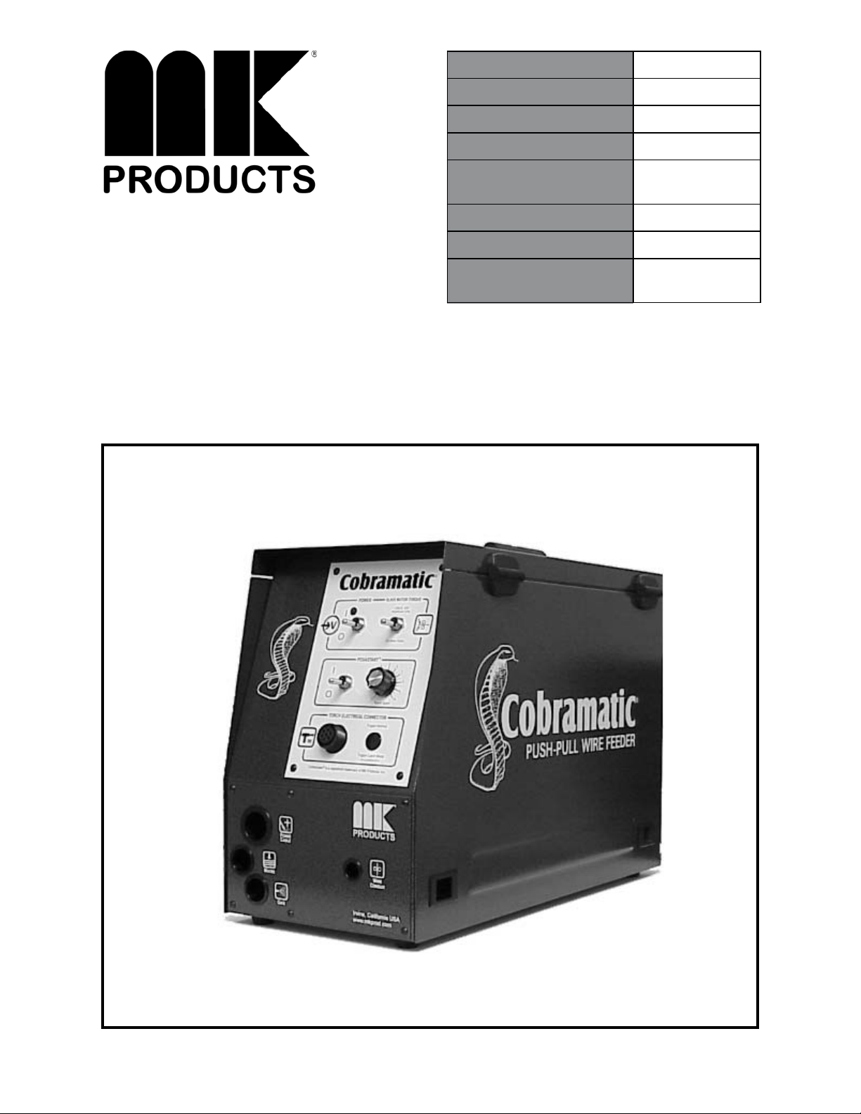
Product Description Cobramatic®
MK Manual Part Number 091-0495
MK Form Number CB/OM-5
NWSA Form Number 550
Effective with Serial
Number
Voltage Rating 115 VAC
Printing/Rev. Date August 2002 D
This manual applies to the
following model numbers
12001
150-005
Cobramatic® Wire Feed Cabinet
16882 Armstrong Ave., Irvine, CA 92606 Tel 949/863-1234 Fax 949/474-1428 www.mkproducts.com
Page 2

SAFETY CONSIDERATIONS
ELECTRIC ARC WELDING EQUIPMENT
CAUTION : READ BEFORE ATTEMPTING INSTALLATION, OPERATION
OR MAINTENANCE OF THIS EQUIPMENT
1-1 INTRODUCTION
This equipment is intended for ultimate
application by commercial/industrial users and
for operation by persons trained and
experienced in the use and maintenance of
welding equipment. Operation should not be
undertaken without adequate training in the
use of such equipment. Training is available
from many public and private schools or similar
facilities.
Safe practices in the installation, operation
and maintenance of this equipment requires
proper training in the art, a careful study of the
information provided with the equipment, and
the use of common sense. Rules for safe use
are generally provided by suppliers of welding
power sources, compressed gas suppliers, and
electrode suppliers. Careful compliance with
these rules will promote safe use of this
equipment.
The following Safety Rules cover some of the
more generally found situations. READ THEM
CAREFULLY. In case of any doubt, obtain
qualifi ed help before proceeding.
1-2 GENERAL PRECAUTIONS
A. B
URN PREVENTION
ELECTRIC ARC WELDING PRODUCES HIGH
INTENSITY HEAT AND ULTRAVIOLET
RADIANT ENERGY WHICH MAY CAUSE
SERIOUS AND PERMANENT EYE DAMAGE
AND WHICH MAY DAMAGE ANY EXPOSED
SKIN AREAS.
Wear helmet with safety goggles or glasses
with side shields underneath, appropriate fi lter
lenses or plates (protected by clear cover
glass). This is a must for welding or cutting
(and chipping) to protect the eyes from radiant
energy and fl ying metal. Replace cover glass
when broken, pitted, or spattered.
Medical fi rst aid and eye treatment. First aid
facilities and a qualifi ed fi rst aid person should
be available for each shift unless medical
facilities are close by for immediate treatment
of fl ash burns of the eyes and skin burns.
Wear protective clothing - leather (or asbestos)
gauntlet gloves, hat, and high safety-toe shoes.
Button shirt collar and pocket fl aps, and wear
cuffl ess trousers to avoid entry of sparks and
slag.
Avoid oily or greasy clothing. A spark may
ignite them.
Flammable hair preparations should not be
used by persons intending to weld or cut.
Hot metal such as electrode stubs and work
pieces should never be handled without gloves.
Ear plugs should be worn when working on
overhead or in a confi ned space. A hard hat should
be worn when others work overhead.
OXIC FUME PREVENTION
B. T
WARNING: The use of this product may result
in exposure to chemicals known to the State of
California to cause cancer and birth defects or
other reproductive harm.
Adequate ventilation. Severe discomfort, illness
or death can result from fumes, vapors, heat, or
oxygen enrichment or depletion that welding (or
cutting) may produce. Prevent them with adequate
ventilation. NEVER ventilate with oxygen.
Lead-, cadmium-, zinc-, mercury-, beryllium-bearing
and similar materials, when welded or cut, may
produce harmful concentrations of toxic fumes.
Adequate local exhaust ventilation must be used, or
each person in the area, as well as the operator,
must wear an air-supplied respirator. For beryllium,
both must be used.
Metals coated with or containing materials that emit
toxic fumes should not be heated unless coating
is removed form the work surface, the area is well
ventilated, or the operator wears an air-supplied
respirator.
Work in a confi ned space only while it is being
ventilated and, if necessary, while wearing an airsupplied respirator.
Gas leaks in a confi ned space should be avoided.
Leaked gas in large quantities can change oxygen
concentration dangerously. Do not bring gas
cylinders into a confi ned space.
Leaving confi ned space, shut OFF gas supply at
source to prevent possible accumulation of gases
in the space if downstream valves have been
accidentally opened or left open. Check to be sure
that the space is safe before reentering it.
Vapors from chlorinated solvents can be
decomposed by the heat of the arc (or fl ame) to
form PHOSGENE, a highly toxic gas, and other
lung and eye irritating products. The ultraviolet
(radiant) energy of the arc can also decompose
trichloroethylene and perchloroethylene vapors to
form phosgene. DO NOT WELD or cut where
solvent vapors can be drawn into the welding or
cutting atmosphere or where the radiant energy can
penetrate to atmospheres containing even minute
amounts of trichloroethylene or perchloroethylene.
C. F
IRE AND EXPLOSION PREVENTION
Causes of fi re and explosion are: combustibles
reached by the arc, fl ame, fl ying sparks, hot slag, or
heated material, misuse of compressed gases and
cylinders, and short circuits.
BE AWARE THA T fl ying sparks or falling slag can
pass through cracks, along pipes, through windows
or doors, and through wall or fl oor openings,
out of sight of the goggled operator. Sparks
can fl y many feet.
To prevent fi res and explosion:
Keep equipment clean and operable, free of
oil, grease, and (in electrical parts) of metallic
particles that can cause short circuits.
If combustibles are in area, do NOT weld or
cut. Move the work if practicable, to an area
free of combustibles. Avoid paint spray rooms,
dip tanks, storage areas, ventilators. If the
work cannot be moved, move combustibles at
least 35 feet away, out of reach of sparks and
heat; or protect against ignition with suitable
and snug-fi tting, fi re-resistant covers or shields.
Walls touching combustibles on opposite sides
should not be welded on (or cut). Walls,
ceilings, and fl oor near work should be
protected by heat-resistant covers or shields.
Fire watcher must be standing by with suitable
fi re extinguishing equipment during and for
some time after welding or cutting if:
1. Appreciable combustibles (including building
construction) are within 35 feet.
2. Appreciable combustibles are further than
35 feet, but can be ignited by sparks.
3. Openings (concealed or visible) in fl oors or
walls within 35 feet may expose combustibles
to sparks.
4. Combustibles adjacent to walls, ceilings,
roofs, or metal partitions can be ignited by
radiant or conducted heat.
Hot work permit should be obtained before
operation to ensure supervisor’s approval that
adequate precautions have been taken.
After work is done, check that area is free of
sparks, glowing embers, and fl ames.
An empty container that held combustibles, or
that can produce fl ammable or toxic vapors
when heated, must never be welded on or
cut, unless container has fi rst been cleaned in
accordance with industry standards.
This includes: a thorough steam or caustic
cleaning (or a solvent of water washing,
depending on the combustible’s solubility),
followed by purging and inerting with nitrogen
or carbon dioxide, and using protective
equipment.
Water-fi lling just below working level may
substitute for inerting.
A container with unknown contents should be
cleaned (see paragraph above). Do NOT
depend on sense of smell or sight to determine
Cobramatic® Safety - page i
Page 3

if it is safe to weld or cut.
Hollow castings or containers must be vented
before welding or cutting. They can explode.
Explosive atmospheres. NEVER weld or cut
where the air may contain fl ammable dust, gas,
or liquid vapors (such as gasoline).
OMPRESSED GAS EQUIPMENT
D. C
The safe handling of compressed gas
equipment is detailed in numerous industry
publications. The following general rules cover
many of the most common situations.
1. Pressure Regulators
Regulator relief valve is designed to protect
only the regulator from overpressure; it is
not intended to protect any downstream
equipment. Provide such protection with one or
more relief devices.
Never connect a regulator to a cylinder
containing gas other than that for which the
regulator was designed.
Remove faulty regulator from service
immediately for repair (fi rst close cylinder
valve). The following symptoms indicate a
faulty regulator:
Leaks - if gas leaks externally.
Excessive Creep - if delivery pressure
continues to rise with downstream valve
closed.
Faulty Gauge - if gauge pointer does not move
off stop pin when pressurized, nor returns to
stop pin after pressure release.
Repair. Do NOT attempt repair. Send
faulty regulators for repair to manufacturer’s
designated repair center, where special
techniques and tools are used by trained
personnel.
2. Cylinders
Cylinders must be handled carefully to prevent
leaks and damage to their walls, valves, or
safety devices:
Avoid electrical circuit contact with cylinders
including third rails, electrical wires, or welding
circuits. They can produced short circuit arcs
that may lead to a serious accident. (See 1-3C)
ICC or DOT marking must be on each cylinder.
It is an assurance of safety when the cylinder is
properly handled.
Identifying gas content. Use only cylinders with
name of gas marked on them; do not rely on
color to identify gas content. Notify supplier
if unmarked. NEVER DEFACE or alter name,
number, or other markings on a cylinder. It is
illegal and hazardous.
Empties: Keep valves closed, replace caps
securely; mark MT; keep them separate from
FULLS, and return promptly.
Prohibited use. Never use a cylinder or its
contents for other than its intended use,
NEVER as a support or roller.
Locate or secure cylinders so they cannot be
knocked over.
Passageways and work areas. Keep cylinders clear
of areas where they may be stuck.
Transporting cylinders. With a crane, use a secure
support such as a platform or cradle. Do NOT lift
cylinders off the ground by their valves or caps, or
by chains, slings, or magnets.
Do NOT expose cylinders to excessive heat,
sparks, slag, and fl ame, etc. that may cause
rupture. Do not allow contents to exceed 55
degrees C (130 degrees F.) Cool with water spray
where such exposure exists.
Protect cylinders, particularly valves from bumps,
falls, falling objects, and weather. Replace caps
securely when moving cylinders.
Stuck valve. Do NOT use a hammer or wrench
to open a cylinder valve that cannot be opened by
hand. Notify your supplier.
Mixing gases. NEVER try to mix any gases in a
cylinder.
NEVER refi ll any cylinder.
Cylinder fi ttings should never be modifi ed or
exchanged.
3. Hose
Prohibited use. Never use hose other than that
designed for the specifi ed gas. A general hose
identifi cation rule is: red for fuel gas, green for
oxygen, and black for inert gases.
Use ferrules or clamps designed for the hose (not
ordinary wire or other substitute) as a binding to
connect hoses to fi ttings.
No copper tubing splices. Use only standard brass
fi ttings to splice hose.
Avoid long runs to prevent kinks and abuse.
Suspend hose off ground to keep it from being run
over, stepped on, or otherwise damaged.
Coil excess hose to prevent kinks and tangles.
Protect hose from damage by sharp edges, and by
sparks, slag, and open fl ame.
Examine hose regularly for leaks, wear, and loose
connections. Immerse pressured hose in water;
bubbles indicate leaks
Repair leaky or worn hose by cutting area out and
splicing. Do NOT use tape.
4. Proper Connections
Clean cylinder valve outlet of impurities that may
clog orifi ces and damage seats before connecting
regulator. Except for hydrogen, crack valve
momentarily, pointing outlet away from people and
sources of ignition. Wipe with a clean, lintless
cloth.
Match regulator to cylinder. Before connecting,
check that the regulator label and cylinder marking
agree, and that the regulator inlet and cylinder
outlet match. NEVER Connect a regulator
designed for a particular gas or gases to a cylinder
containing any other gas.
Tighten connections. When assembling threaded
connections, clean and smooth seats where
necessary. Tighten. If connection leaks,
disassemble, clean, and retighten, using properly
fi tting wrench.
Adapters. Use a CGA adapter (available from
your supplier) between cylinder and regulator,
if one is required. Use two wrenches to
tighten adapter marked RIGHT and LEFT
HAND threads.
Regulator outlet (or hose) connections may be
identifi ed by right hand threads for oxygen and
left hand threads (with grooved hex on nut or
shank) for fuel gas.
5. Pressurizing Steps:
Drain regulator of residual gas through suitable
vent before opening cylinder (or manifold
valve) by turning adjusting screw in (clockwise).
Draining prevents excessive compression heat
at high pressure seat by allowing seat to
open on pressurization. Leave adjusting screw
engaged slightly on single-stage regulators.
Stand to side of regulator while opening
cylinder valve.
Open cylinder valve slowly so that regulator
pressure increases slowly. When gauge
is pressurized (gauge reaches regulator
maximum) leave cylinder valve in following
position: for oxygen and inert gases, open fully
to seal stem against possible leak; for fuel gas,
open to less than one turn to permit quick
emergency shut-of
f.
Use pressure charts (available from your
supplier) for safe and effi cient recommended
pressure settings on regulators.
Check for leaks on fi rst pressurization and
regularly thereafter. Brush with soap solution.
Bubbles indicate leaks. Clean off soapy water
after test; dried soap is combustible.
E. U
SER RESPONSIBILITIES
Follow all Safety Rules.
Remove leaky or defective equipment from
service immediately for repair. Read and follow
user manual instructions.
F. L
EAVING EQUIPMENT UNATTENDED
Close gas supply at source and drain gas.
G. ROPE STAGING-SUPPORT
Rope staging-support should not be used for
welding or cutting operation; rope may burn.
1-3 ARC WELDING
Comply with precautions in 1-1, 1-2, and this
section. Arc Welding, properly done, is a
safe process, but a careless operator invites
trouble. The equipment carries high currents
at signifi cant voltages. The arc is very bright
and hot. Sparks fl y, fumes rise, ultraviolet and
infrared energy radiates, weldments are hot,
and compressed gases may be used. The
wise operator avoids unnecessary risks and
protects himself and others from accidents.
A. B
URN PROTECTION
Comply with precautions in 1-2.
The welding arc is intense and visibly bright.
Its radiation can damage eyes, penetrate
lightweight clothing, refl ect from light-colored
surfaces, and burn the skin and eyes.
Skin burns resemble acute sunburn; those
from gas-shielded arcs are more severe and
Cobramatic® Safety - page ii
Page 4

painful. DON’T GET BURNED; COMPLY
WITH PRECAUTIONS.
1. Protective Clothing
Wear long-sleeve clothing in addition to gloves,
hat, and shoes. As necessary, use additional
protective clothing such as leather jacket or
sleeves, fl ameproof apron, and fi re-resistant
leggings. Avoid outer garments of untreated
cotton.
Bare skin protection. Wear dark, substantial
clothing. Button collar to protect chest and
neck, and button pockets to prevent entry of
sparks.
2. Eye and Head Protection
Protect eyes from exposure to arc. Eyes may
be damaged by radiant energy when exposed
to the electric arc, even when not looking in the
direction of the arc. Never look at an electric
arc without protection.
Welding helmet or shield containing a fi lter
plate shade no. 12 or denser must be used
when welding. Place over face before striking
arc.
Protect fi lter plate with a clear cover plate.
Cracked or broken helmet or shield should
NOT be worn; radiation can be passed through
to cause burns.
Cracked, broken, or loose fi lter plates must be
replaced IMMEDIATELY. Replace clear cover
plate when broken, pitted, or spattered.
Flash goggles with side shields MUST be worn
under the helmet to give some protection to the
eyes should the helmet not be lowered over the
face before an arc is struck. Looking at an arc
momentarily with unprotected eyes (particularly
a high intensity gas-shielded arc) can cause a
retinal burn that may leave a permanent dark
area in the fi eld of vision.
3. Protection of Nearby Personnel
Enclose the welding area. For production
welding, a separate room or enclosed bay is
best. In open areas, surround the operation
with low-refl ective, noncombustible screens or
panels. Allow for free air circulation, particularly
at fl oor level.
Viewing the weld. Provide face shields for all
persons who will be looking directly at the weld.
Others working in area. See that all persons
are wearing fl ash goggles.
Before starting to weld, make sure that screen
fl aps or bay doors are closed.
OXIC FUME PREVENTION
B. T
Comply with precautions in 1-2B.
Generator engine exhaust must be vented to
the outside air. Carbon monoxide can kill.
C. F
IRE AND EXPLOSION PREVENTION
Comply with precautions in 1-2C.
Equipment’s rated capacity. Do not overload
arc welding equipment. It may overheat cables
and cause a fi re.
Loose cable connections may overheat or fl ash
and cause afi re.
Never strike an arc on a cylinder or other pressure
vessel. It creates a brittle area that can cause a
violent rupture or lead to such a rupture later under
rough handling.
OMPRESSED GAS EQUIPMENT
D. C
Comply with precautions in 1-2D.
E. S
HOCK PREVENTION
Exposed electrically hot conductors or other bare
metal in the welding circuit, or in ungrounded,
electrically-HOT
equipment can fatally shock a person whose body
becomes a conductor. DO NOT STAND, SIT, LIE,
LEAN ON, OR TOUCH a wet surface when welding
without suitable protection.
To protect against shock:
Keep body and clothing dry. Never work in damp
area without adequate insulation against electrical
shock. Stay on a dry duckboard, or rubber mat
when dampness or sweat cannot be avoided.
Sweat, sea water, or moisture between body and
an electrically HOT part - or grounded metal reduces the body surface electrical resistance,
enabling dangerous and possibly lethal currents to
fl ow through the body.
1. Grounding the Equipment
When installing, connect the frames of each unit
such as welding power source, control, work
table, and water circulator to the building ground.
Conductors must be adequate to carry ground
currents safely. Equipment made electrically HOT
by stray currents may shock, possibly fatally. Do
NOT GROUND to electrical conduit, or to a pipe
carrying ANY gas or a fl ammable liquid such as oil
or fuel.
Three-phase connection. Check phase requirement
of equipment before installing. If only three-phase
power is available, connect single-phase equipment
to only two wires of the three-phase line. Do
NOT connect the equipment ground lead to the
third (live) wire, or the equipment will become
electrically HOT - a dangerous condition that can
shock, possibly fatally.
Before welding, check ground for continuity. Be
sure conductors are touching bare metal of
equipment frames at connections.
If a line cord with a ground lead is provided with the
equipment for connection to a switch box, connect
the ground lead to the grounded switch box. If
a three-prong plug is added for connection to a
grounded mating receptacle, the ground lead must
be connected to the ground prong only. If the line
cord comes with a three-prong plug, connect to a
grounded mating receptacle. Never remove the
ground prong from a plug, or use a plug with a
broken ground prong.
2. Connectors
Fully insulated lock-type connectors should be used
to join welding cable lengths.
3. Cables
Frequently inspect cables for wear, cracks, and
damage. IMMEDIATELY REPLACE those with
excessively worn or damaged insulation to avoid
possibly lethal shock from bared cable. Cables
with damaged areas may be taped to give
resistance equivalent to original cable.
Keep cable dry, free of oil and grease, and
protected from hot metal and sparks.
4. Terminals and Other Exposed Parts
Terminals and other exposed parts of electrical
units should have insulating covers secured
before operation.
5. Electrode Wire
Electrode wire becomes electrically HOT when
the power switch of gas metal-arc welding
equipment is ON and welding gun trigger is
pressed. Keep hands and body clear of wire
and other HOT parts.
6. Safety Devices
Safety devices such as interlocks and circuit
breakers should not be disconnected or
shunted out.
Before installation, inspection, or service of
equipment, shut OFF all power, and remove
line fuses (or lock or red-tag switches) to
prevent accidental turning ON of power.
Disconnect all cables from welding power
source, and pull all 115 volts line-cord plugs.
Do not open power circuit or change polarity
while welding. If, in an emergency, it must
be disconnected, guard against shock burns or
fl ash from switch arcing.
Leaving equipment unattended. Always shut
OFF, and disconnect all power to equipment.
Power disconnect switch must be available
near the welding power source.
Cobramatic® Safety - page iii
Page 5
For selecting a quality product. We want you to take
Thank You
pride in operating this product...as much pride as we
have in bringing the product to you!
Please Examine Carton and Equipment For Damage Immediately
When this equipment is shipped, title passes to the purchaser upon receipt by the
carrier. Consequently, claims for material damaged in shipment must be made by the
purchaser against the transportation company at the time the shipment is received.
Please record your equipment identification information below for future reference. This
information can be found on your machine nameplate.
Model Name & Number _____________________
Code & Serial Number _____________________
Date of Purchase _____________________
Whenever you request replacements parts for, or information on this equipment always
supply the information you have recorded above.
Read this Owner’s Manual completely before attempting to use this equipment. Save this manual
and keep it handy for quick reference. Pay particular attention to the safety instructions we
have provided for your protection.
Cobramatic® Owner’s Manual - page iv
Page 6
Table of Contents
Saftey Guidelines
Installation .........................................................................Section A
Technical Specifi cations .......................................................................1
Machine Grounding .............................................................................1
Machine Location ................................................................................1
Input Power Connections .....................................................................1
Wire Threading Procedure ...................................................................2
Welding Torch Connections ..................................................................4
Operation............................................................................Section B
General Description .............................................................................4
Recommended Processes and Equiment ...............................................4
Controls and Settings ..........................................................................4
POSA Start Operating Procedure...........................................................5
Accessories .........................................................................Section C
Optional Kits .......................................................................................7
Maintenance .......................................................................Section D
Routine Maintenance ...........................................................................7
Testing the Feeder...............................................................................8
Testing the Torch ................................................................................9
Troubleshooting .................................................................Section E
Troubleshooting Guide .......................................................................10
Diagrams/Parts List ..........................................................Section F
Main PC Boards .................................................................................13
Mechanical .......................................................................................14
Electrical ...........................................................................................25
Warranty Repair Stations
Safety Warnings
Warranty
Cobramatic® Owner’s Manual
Page 7

This page intentionally blank
Cobramatic® Owner’s Manual
Page 8

Section A Installation
Technical Specifi cations
Wire Diameter Capacity .......................................030 - 1/16” ALL Types
Wire Spool Capacity ...........................................12” Standard
(Insulated or Non-Insulated)
Power Input ......................................................... 115 VAC 50/60 Hz,
............................................................................... 150 Watts Peak (1.3 amps)
Weight ..................................................................41 pounds
Shipping Weight .................................................46 pounds
For Use with torch prefi x number .....................14X, 16X, 21X & 22X
Support Equipment Required
C.V. or C.C. Power Source of Suffi cient Capacity for
Regulated Gas Supply and Hoses.
Properly Sized Power Leads from Power Source to Wire Feeder and Ground.
Coolant Recommendations
Coolant Recirculator and Hose Capable of Providing a Minimum of 1 qt/min.
at 45 p.s.i. when using water cooled torches.
Use a name-brand additive which does not contain reactive sulphur or
chlorine and does not react with copper, brass, or aluminum.
Check coolant periodically to remain within limits of the following:
A. Coolant Flow rate - 1 quart/minute at 45 p.s.i.
B. Resistivity - 10K ohms/centimeter
C. Ph Range - 5.5-8.5
D. Particle Size - .005”
MK Recommended Coolant Solution:
1 part ethylene glycol
3 parts distilled water
1 teaspoon liquid glycerin
Your Needs.
Machine Grounding
The Cobramatic® and GMAW wire feeders are ground to the power source
through the input cable. The power source grounding terminal must be
properly connected to electrical ground per the power source operating
manual.
Mounting Location
The cabinet should be placed in a location where it can be protected from
damage. Lead lengths and accessibility must also be considered when
installing the cabinet.
Input Connections
(See Cabinet and Torch Hook-Up in the Appendix)
115 VAC
Your Wire Feeder comes factory ready with a standard 3-prong plug ready
to connect into any standard 120VAC, 15
wired harnesses are available for different power supplies. See part numbers
and description of each in the OPTIONAL KITS section of this manual.
The 115 VAC is connected to the PC Board on terminal strip J5 #1 (neutral)
and #2 (hot) and Ground to the Cabinet chassis. See diagram in the
appendix.
Cobramatic® Owner’s Manual - page 1
A receptacle. Several optional, pre-
Page 9
Shielding Gas
In accordance with the required support equipment, the customer must
provide a cylinder of shielding gas, a pressure regulator, a fl ow control valve,
and a hose from the fl ow control valve to the left bottom-most fi tting on the
power block.
The end of the hose must have a male connector to fi t the female 5/8-18
brass fi tting. Use a 11/16” wrench to tighten.
Coolant Supply and Return (if used)
Using a recirculator with properly mixed coolant, as previously described,
connect the coolant RETURN hose to the left middle fi tting on the power
block. Connect the coolant SUPPL
Y hose to the left top-most fi tting on the
power block.
The coolant hoses must have a male 5/8-18 left-hand thread to connect to the
power block fi ttings. Use an 11/16” wrench to tighten.
Welding Power
The electrode cable coming from the welding power supply should be affi xed
with a 1/2” copper ring lug. Using a 9/16” wrench, remove the 3/8” bolt and
washer from the bottom of the power block. Use a 9/16” wrench to tighten.
It is recommended to make this connection last, after connecting the gas and
coolant hoses. Reference Input Connections fi gure in the
Appendix.
Wire Threading Procedure
Wire Spool Installation
Release latches, and open right side door of cabinet.
Remove spool retainer from spindle hub.
Raise wire retainer bar to latched position.
Install wire spool onto spindle hub so that wire feeds from bottom of spool
towards slave motor. Make sure that the hole in the spool aligns with pin
on spindle hub. The white dot on the end of the spindle hub will aid in
this alignment.
Replace the spool retainer nut.
Lower the wire retainer bar onto the spool.
Wire Spool Drag Setting
NOTE:
Standard factory setting of the Spindle T
ension Knob is set for All Other Wires.
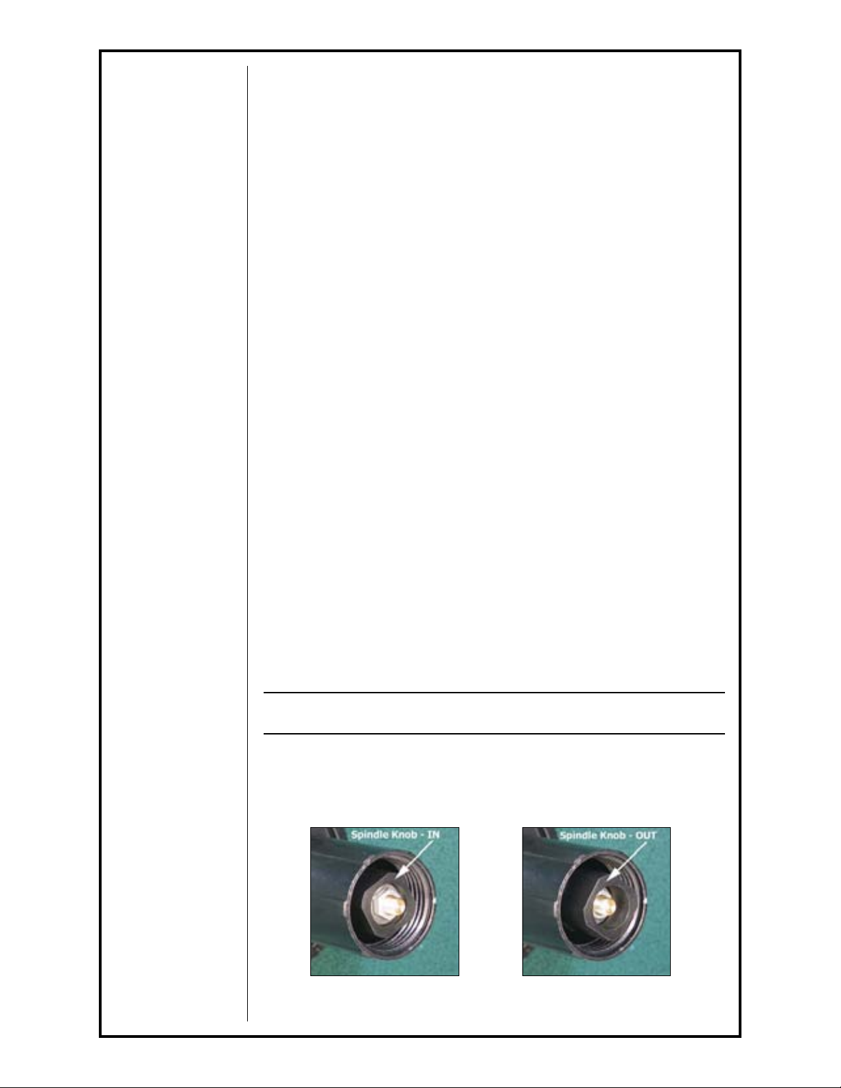
There are two visible position settings for this Knob, IN - All Other Wires
(Fig. 1) and, OUT - .030/.035 Al Only (Fig. 2). The Spindle Tension Knob
must be set to match the Wire Size Selector Switch on the Cobramatic®
front panel.
IN - All other wires
Figure 1
Cobramatic® Owner’s Manual - page 2
OUT - .030/.035 Aluminum ONLY
Figure 2
Page 10
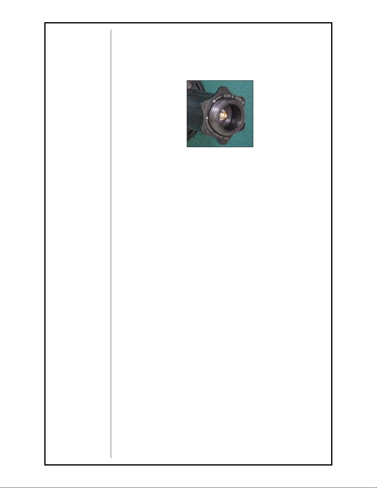
To change this setting, it is easier done without the spool of wire on the spindle. Remove the wire spool retainer and re-install it reversed back onto the
Spindle Tension Knob (Fig. 3). In the “Tool Mode”, the square shaped end of
the retainer fi ts onto the Knob. Grab the retainer and turn in the COUNTER-
CLOCKWISE direction until it stops. The Knob is now set to the OUT position (.030/.035 AL Only).
Wire Spool Retainer In "Tool Mode";
used to change spindle drag.
Figure 3
To reset the Knob back to the factory setting of All Other Wires, use the
retainer as described above, and turn in the CLOCKWISE direction until it
stops. The Knob is now set to the IN position. Turning the retainer and
Knob in this direction may require more effort, since turning CLOCKWISE is
working against a spring.
Load wire spool onto spindle according to the previous instructions.
Replace the spool retainer nut.
Lower the wire retainer bar onto the spool.
Threading Procedure
Place wire size selector switch on front panel to the correct position for the
wire being used.
Loosen end of wire from spool and cut off any kinked or bent portions.
Unreel and straighten out fi
rst 6” to 8” of wire.
Raise wire type lever to center position.
Route wire into inlet guide, along drive roll groove, and into wire conduit.
Flip wire type lever to show type of wire being used.
Tighten the torch pressure adjusting knob so the wire will be picked up and
fed through the contact tip. Proper tension is achieved when wire does not
slip if a small amount of pressure is added to the wire as it exits the tip.
Wire Retainer Bar
The design of the patented Cobramatic® Wire Retainer Bar performs two
very important and very basic functions of the wire feeder: a) spool drag
tension, and b) wire maintenance on the spool.
The spool drag tension is set by lowering the wire retainer bar onto the wire
inside of the spool. The spring tension of the wire retainer bar applies enough
pressure on the spool so that when the torch trigger is released, engaging the
brake pall, the spool does not overrun kicking wire of
f the spool.
Wire maintenance on the spool is performed by the applied pressure of the
wire retainer bar spread across the coiled wire on the spool. The replaceable
pad (P/N 437-0255) of the wire retainer bar is designed to hold the wire on
the spool, maintaining the smooth layering of the wire and keeping it from
jumping off, and possibly, electrically shorting to the cabinet chassis.
Cobramatic® Owner’s Manual - page 3
Page 11

Welding Torch Connections
Work Cable
Connect a work lead of suffi cient size and length (see table below) between
the proper output stud on the power source and the work. Be sure the
connection to the work makes tight metal to metal electrical contact. Poor
work lead connections can result in poor arc initiation, poor weld results and
activation of the ground lead protector
Work Lead Lengths
Current 60% Up to 50ft. 10-100ft.
Duty Cycle (15.2m) (15.2-30.4m)
300A 0 (53mm) 0 (67mm)
400A 00 (67mm) 00 (85mm)
500A 00 (67mm) 00 (85mm)
600A 000 (85mm) 000 (107mm)
Control Cable
The 7-Pin “W” Clocked connector screws onto the mating receptacle on the
front panel of the wire feeder.
voltage, potentiometer control & trigger) to and from the feeder to the torch.
Wire Conduit Inlet
Front panel access to attach conduit to front of slave motor assembly.
Power Cable Inlet
Front panel access to attach power cable (air or water) to top of power block.
This provides all electrical signals (motor
.
Gas Inlet
Front panel access to attach gas hose to bottom fi tting of power block.
Water Inlet (For Water Cooled Torches)
Front panel access to connect the water hose to the middle fi tting on the
power block.
Section B Operation
General
The AC slave motor in the feeder runs at a fast, constant speed, but has very
low torque. It is always trying to feed more wire than the torch motor wants,
and when the motor gets all it wants, it slows the slave motor preventing a
bird’s nest. Because of the low torque produced by the slave motor, a brake
system is used to prevent wire overrun rather than tension. The spool drag
tension is produced by the patented Wire Retainer Bar mechanism to keep
the wire slightly taut. The 24 VDC torch pull motor is controlled by a solid
state speed control and a potentiometer located in the torch.
Recommended Processes and Equipment
The Cobramatic® is recommended for use in the GMAW and FCAW welding
applications. It is recommended for use with constant voltage power sources.
The Cobramatic® is capable of feeding wires (diameter capacity) ranging
from .023” through .045” solid/cored and .030” through 1/16” aluminum.
Controls and Settings
On/Off Switch
Placing the switch in the “ON” position energizes the feeder circuitry and the
power indicator light.
Wire Size Selector Switch
The wire size selector switch changes the torque of the slave motor for the
wire you are using. When in the .030-.035 aluminum only position, the slave
Cobramatic® Owner’s Manual - page 4
Page 12
motor produces approximately 1 1/2 lbs. inches and approximately 4 1/2 lbs.
inches when in the all other wires position.
NOTE:
Operating the cabinet with the switch in the wrong
position will cause wir
e feed diffi culties.
Posa Start Controls
The Posa Start Run-in Speed Control, located on the front panel, provides
adjustment for slow wire run-in. Once the arc has been established, the
wire feed speed is automatically changed from the slow run-in speed to the
welding speed set on the torch potentiometer.
Posa Start Operating Procedure
General
The Posa Start Run-in Speed Control, located on the front panel, provides
adjustment for slow wire run-in. Once the arc has been established, the
wire feed speed is automatically changed from the slow run-in speed to the
welding speed set on the torch potentiometer.
The Posa Start feature allows the Cobramatic® to be used in combination
with constant current DC welding power sources of open circuit voltage in
excess of 55 volts - also, any constant voltage welding power source capable
of a minimum of 50 amps.
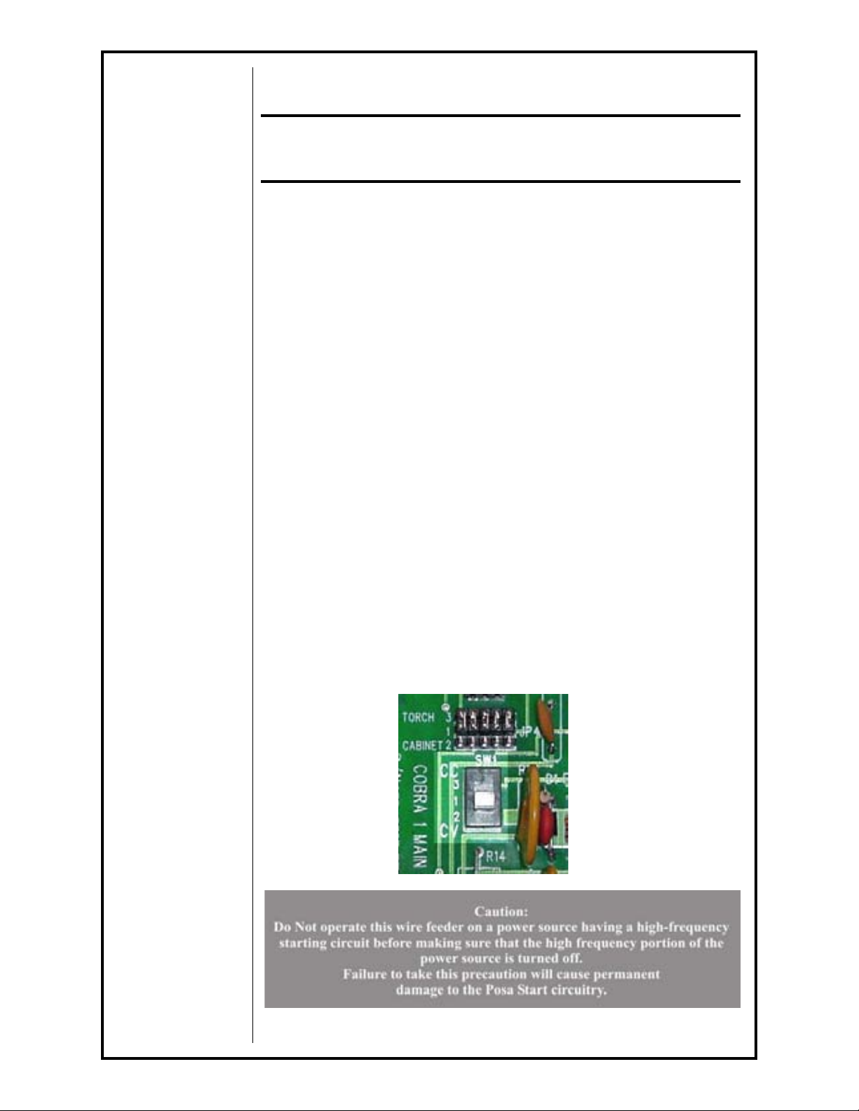
Main Board Con
fi guration
Factory supplied, this switch will be shipped in the CV (Constant Voltage)
position. This designates the type of welding power supply the Cobramatic
is connected to. If the the power supply is a Constant Current type (CC), the
switch should be moved to the CC position.
This switch is designed to confi
gure the main board so that the OCV (Open
CIrcuit Voltage) and welding current (measured at J1 current sensor) properly engages the PosaStart
®
cirtcuit to tranfer from the run-in wire speed to
welding wire speed.
If the position of the switch does not match that of the power supply, the
PosaStart
®
circuit will not engage and wire speed transfer will not occur.
Cobramatic® Owner’s Manual - page 5
Page 13
Note:
Reverse polarity MUST be used.
Posa Start Connections
Attach the #14 single black lead which extends from the back of the cabinet
to the negative terminal of the power supply or work ground. The Posa Start
lead is internally connected to the P
.C. board on terminal strip J6, terminal 2.
CV Posa Start Operations
Attach Cobramatic® to CV power source according to the installation instructions.
Turn the Cobramatic® to the
“ON” position and the Posa Start to the “OFF”
position.
Adjust power source to desired voltage for your weld condition.
Depress gun trigger and adjust wire feed speed at gun to match voltage set-
ting. If approximate wire feed is not known, it is better to start with excess
wire feed rather than too little, in order to prevent a “burn-back”.
Turn the Posa Start switch to the “ON” position. Press torch trigger and,
using Run-in Speed Control, adjust wire feed rate to approximately 10% of
welding wire speed set at torch.
Strike an arc, and adjust wire feed rate at gun until correct condition is
achieved.
CC Posa Start Operation
Attach the Cobramatic® to a CC power source according to the installation
instructions.
Insure power supply high frequency switch is in the “OFF” position, and
power supply is set to DC reverse polarity.
The power supply contactor should be set to “Remote”
or “Tig” and the
amperage control set to “Panel” or “Standard” depending on power supply.
Turn the Cobramatic® power switch to the “ON” position and the Posa Start
switch to the “OFF” position.
Adjust power source to desired amperage for your weld condition.
Press gun trigger and adjust wire feed speed at gun to match current setting.
If approximate wire feed speed is not known, it is better to start with excess
wire feed rather than too little, in order to prevent possible damage to the
contact tip.
Turn Posa Start switch to the “ON” position. Press torch trigger and, using
Run-in Speed Control, adjust wire feed speed to approximately 10% of welding wire speed set at torch.
Strike an arc; if the wire stubs out, reduce wire feed rate at gun, or increase
amperage setting on power source.
NOTE:
Because the Posa Start Run-in Speed always remains a per
centage
of the actual welding wire feed rate, the Posa Start run-in speed
will always slow down or speed up proportional to any
adjustment you now make at the gun. Therefore, if you slow down
the welding wire feed speed, you will have to increase
the Run-in Speed setting.
Cobramatic® Owner’s Manual - page 6
Page 14

Section C OPTIONAL KITS
The following is a list of Optional Kits available for the Cobramatic® Wire
Feeder.
A detailed description of each kit is given later in this section.
P/N Description
005-0316 8ft Interface Cable for Miller 14-Pin, 115VAC
005-0658 25ft Interface Cable for Miller 14-Pin, 115VAC
005-0608 8ft Interface Cable for Lincoln 14-Pin, 115VAC
005-0659 25ft Interface Cable for Lincoln 14-Pin, 115VAC
005-0674 Gas Purge/Trigger Latch Kit
005-0630 8ft Interface Cable for Thermal Arc 19-Pin, 1115VAC
005-0614 8ft Interface Cable for ESAB 19-Pin, 1115VAC
005-0316 8ft Interface Cable for Miller 14-Pin, 115VAC
005-0658 25ft Interface Cable for Miller 14-Pin, 115VAC
When properly connected, these interface cables will supply all the necessary signals and power needed, from most Miller welding power supplies: a
Closing Contact signal and 115V
005-0608 8ft Interface Cable for Lincoln 14-Pin, 115VAC
005-0659 25ft Interface Cable for Lincoln 14-Pin, 115VAC
When properly connected, these interface cables will supply all the necessary signals and power needed, from most Lincoln Electric welding power
supplies: a Closing Contact signal, Posa-Start Voltage Sensing and 1
input power.
AC input power.
15VAC
005-0630 8ft Interface Cable for Thermal Arc 19-Pin, 1115VAC
When properly connected, these interface cables will supply all the necessary signals and power needed, from most Miller welding power supplies: a
Closing Contact signal and 115V
005-0614 8ft Interface Cable for ESAB 19-Pin, 1115VAC
When properly connected, these interface cables will supply all the necessary signals and power needed, from most Lincoln Electric welding power
supplies: a Closing Contact signal, Posa-Start Voltage Sensing and 1
input power.
005-0674 Gas Purge/Trigger Latch Kit
The Gas Purge/Trigger Latch Kit is a dual function kit. The kit includes an
easy to install interface control PC board, a 24VAC solenoid for pre and post
purge control, a modifi
switch for activating the Trigger Latch mechanism.
The gas control times have been preset to 0.5 seconds pre-purge and 1.0
seconds post-purge. This offers an optimum amount of inert gas shielding
prior to striking the arc and after the arc has been extinguished.
The Trigger Latch mechanism gives the operator the fl exibility of normal
trigger operation (pull trigger to weld - release trigger to stop). This also
offers the comfort of latched trigger operation (pull trigger once to latch and
weld - pull trigger again to unlatch and stop).
ed valve stem for the welding torch and, a front panel
AC input power.
15VAC
Section D Maintenance
Routine Maintenance
Maintenance of the torch will normally consist of a general cleaning of the
wire guide system, including tubes, drive rolls, and conduits at regular intervals.
Cobramatic® Owner’s Manual - page 7
Page 15

Remove spatter build-up from inside of nozzles with a hardwood stick.
The only parts on the Cobramatic® system that are subject to normal wear
are the conduit, contact tips, gas cups, front body liners, wire guides, drive
and idler rolls. A supply of these parts should be maintained on hand.
If repairs do become necessary, any part can easily be replaced by qualifi ed
maintenance personnel.
Your Cobramatic® is designed to provide years of reliable service. Normal
wear and component failure may require occasional service.
The number of units in operation and the importance of minimal “down time”
will determine to what extent spare parts should be stocked on hand.
Testing the Feeder
Relay K2 Operation
When the torch trigger is pressed, 24VAC is sent to the coil of relay K2.
When K2 is energized, AC is sent to the slave motor, spool brake, and the
AC contactor. Relay K2 is also responsible for sending 24VAC to the speed
control circuit and shorting the torch motor leads together when the trigger is
released for the dynamic braking system. K2 also provides the closing contactor signal.
Testing the Input Power Circuits
The AC circuits are protected by fuse F3. If F3 continually blows, disconnect
J4 (Brake Solenoid), J7 (Slave Motor) and J5-3 & 4 - if connected (AC Contactor Out.) from the PC board. Replace fuse and re-trigger system. If fuse
does not blow, isolate problem by reconnecting J4, J7 and J5-3 & 4 one at a
time until the fuse blows.
Testing the Speed Control
NOTE:
The torch should be tested fi rst and the amphenol must be connected to the
Cobramatic® to perform this test.
Place a voltmeter across diode D10
- 24VDC should be observed, as the torch potentiometer varied.
and press torch trigger.
A reading of 0
Cobramatic® Owner’s Manual - page 8
Page 16
Testing the Torch
Motor Check
Remove the amphenol connector from the cabinet.
Using the torch amphenol, check the resistance across pins “A” and “B”
(motor leads). The resistance across the motor should be between 5-10
ohms.
If an open circuit or short exist, check the motor leads and motor independently
.
Testing the Potentiometer - “W” Clocked
Using the torch amphenol, check the resistance across pin “D” (wiper) and
pin “C”. The resistance should vary from
Check the resistance across pin “D” (wiper) and pin “G”. The resistance
should vary from 5K - 0 ohms.
Testing the Micro Switch
Using the torch amphenol, check for continuity across pins “E” and “F”
when the trigger is pressed.
Remote Potentiometer
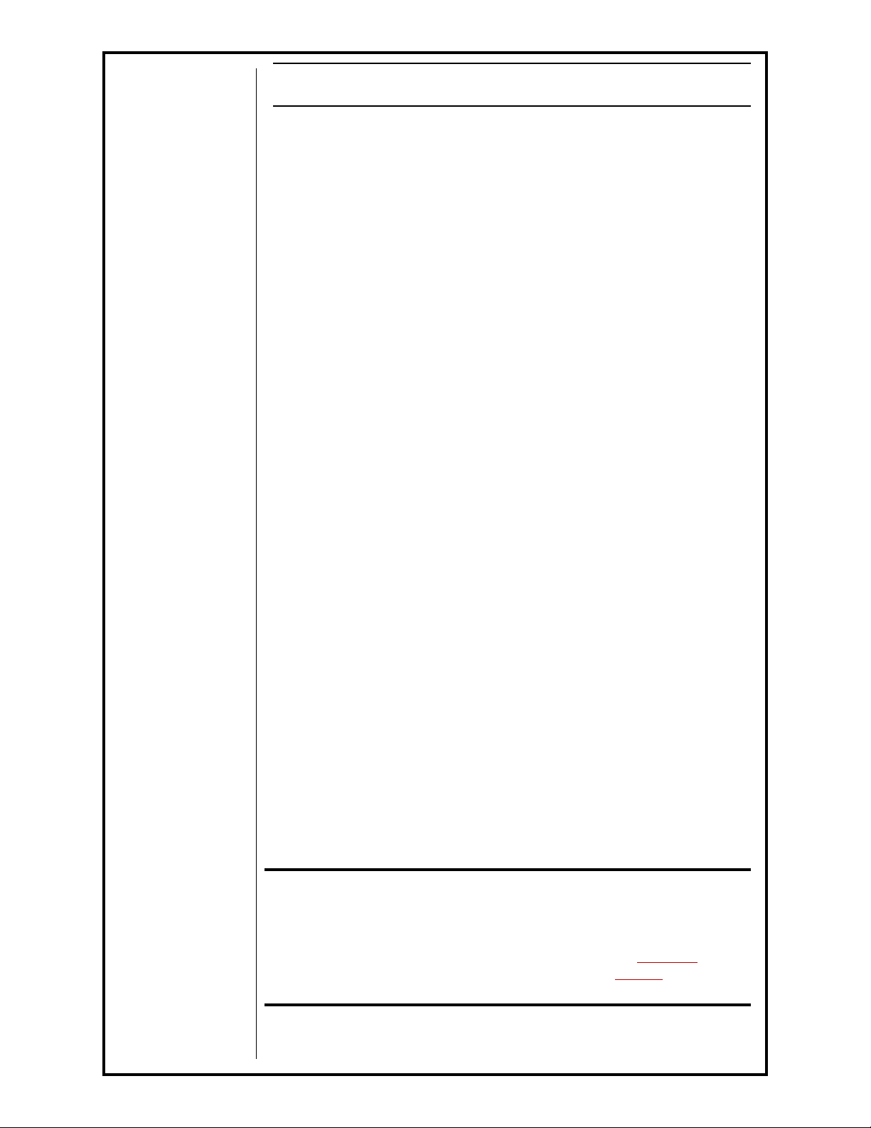
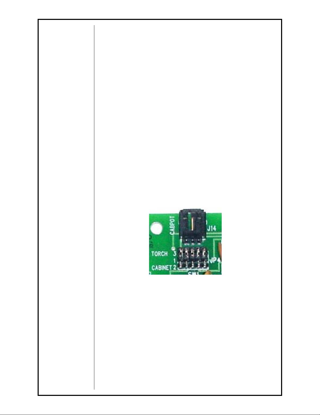
When connecting a remote (cabinet or otherwise) wire speed potentiometer,
the jumpers at JP4 must be moved from the upper position (1-3) to the lower
position (1-2). This will disable the potentiometer in the welding torch.
remote potentiometer leads must then be connected at J14. The cabinet
potentiometer feature applies to installation of this board into Cobramatic
Model 150-003 only, while the remote potentiometer feature applies to
Cobramatic® Models 150-003 & 150-005.
0 - 5K ohms.
The
®
Cobramatic® Owner’s Manual - page 9
Page 17
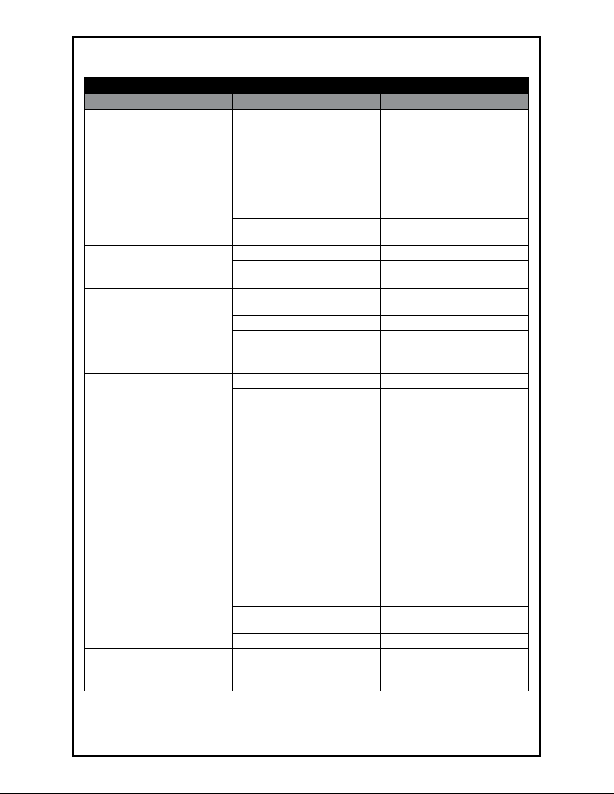
Section E Troubleshooting
Troubleshooting
Symptom Cause Remedy
F3 (2amp) fuse in feeder
blown.
F1 (4amp) fuse in feeder.
No wire feed at torch, feeder
not operating, i.e., no slave
motor or brake solenoid.
Brake solenoid inoperative.
No wire feed at torch, feeder
operating properly.
Wire feeds, but welding wire is
not energized.
Wire feeds erratically.
Wire feeds one speed only.
Wire walks out of drive rolls.
Micro-switch defective/not
being activated. Broken electrical cable.
Relay K2 inoperative. Check/Replace relay K2.
Loose J2, J3, P.C. board con-
nector
Solenoid defective. Replace solenoid.
Relay K2 inoperative.
Bad potentiometer.
Bad torch motor. Check/Replace motor.
Broken electrical cable.
Bad speed control/PCB. Check/Replace P.C. Board.
Loose ot no cable connections. Check all power connections.
Relay K2 not sending contactor
signal.
Contactor control cable loose
or in wrong position.
Welding power source not
working right.
Dirty or worn circuit. Blow out or replace conduit.
Incorrect pressure on drive
rolls.
Idler roll stuck in torch.
Wrong size contact tip. See contact tip table.
Bad potentiometer. Check with meter.
Broken electrical cable in lead
assembly.
Bad speed control Check/Replace P.C. Board.
Idler roll upside-down.
Rear wire guide missing. Replace wire guide.
Check AC circuit. Replace
fuse.
Check motor leads for shorts,
then replace fuse.
Replace switch. Check switch
for operation. Check micro
switch wires for continuity.
Check J2, J3 connectors.
Check for 42VAC across J4-1
and J4-2.
Check potentiometer with
meter.
Check motor and potentiometer wires for continuity.
Check/Replace realy K2.
Check power supply owners
manual for location and type of
contactor signal required, i.e.
closing contacts or AC.
Check power supply for proper
operation.
Adjust pressure at torch.
Check for lock washer under
idler roll, or replace if damaged
or worn.
Check potentiometer wires for
continuity or shorts.
Place groove in idler roll
towards top.
Cobramatic® Owner’s Manual - page 10
Page 18

Section F Appendices
Diagrams/Parts List
Main P.C. Board Connections ..............................................13
Cabinet and Torch Hook-Up ................................................14
001-4011 Cobramatic Assembly ..........................................15
003-2110 Cobramatic Front Panel Assembly ........................17
003-2078 Cobramatic Slave Motor Assembly .......................18
003-2063 Cobramatic Power Block Assembly .......................19
003-2061 Cobramatic Spindle Brake Assembly .....................20
Lincoln Interface Control Cable ...........................................21
Miller Interface Control Cable .............................................22
Thermal Arc Interface Control Cable ...................................23
ESAB Interface Control Cable .............................................24
071-0387 Cobramatic Block Diagram ..................................25
071-0270 Cobramatic Main P.C. Board.................................26
071-0370 Cobramatic Torch Connections .............................27
Cobramatic® Owner’s Manual - page 11
Page 19

This page intentionally blank
Cobramatic® Owner’s Manual - page 12
Page 20
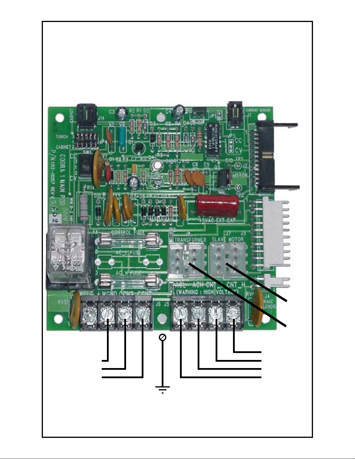
Main P.C. Board Connections
REMOTE
POTENTIOMETER
J14
CURRENT
SENSOR
J1
J2
FRONT
PANEL
J3
FRONT
PANEL
J6
Posa Start Welding Ground
Closing Contacts Out
Closing Contacts Out
Chassis
Ground
Cobramatic® Owner’s Manual - page 13
J5
J4
BRAKE
SOLENOID
J7
SLAVE
MOTOR
J8
TRANSFORMER
115 VAC Contactor Out
115 VAC Contactor Out
Input Power - 115 VAC
Input Power - 115 VAC
Page 21
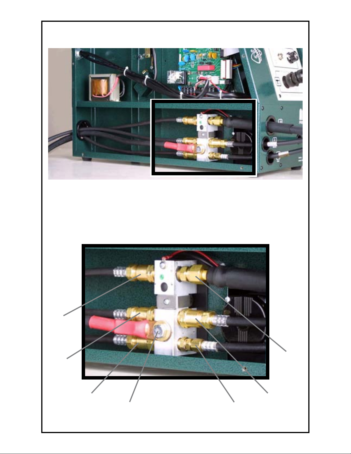
Cabinet and Torch Hook-up
Input Connections Torch Connections
Coolant
Supply
Power/
Coolant
Return
Water In
Shielding
Gas
Welding
Power
Cobramatic® Owner’s Manual - page 14
Gas
Water
Return
Page 22
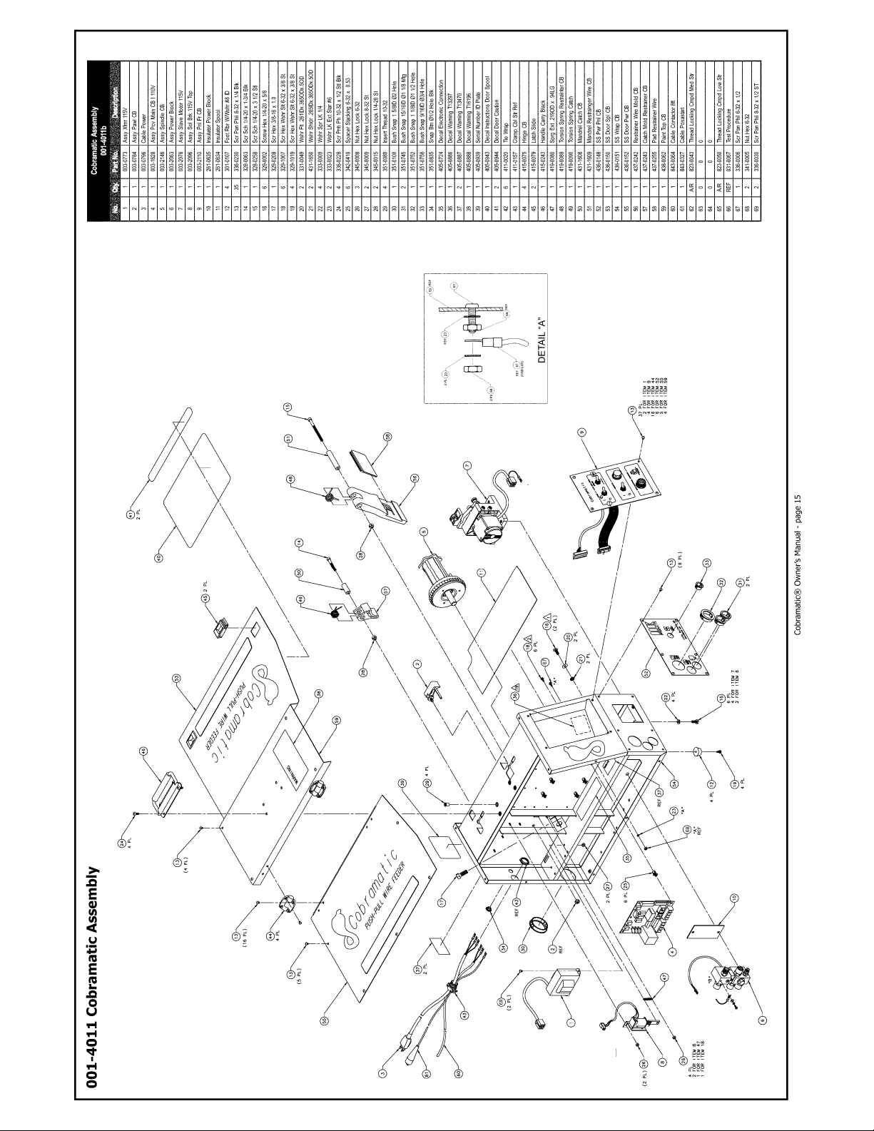
Cobramatic® Owner’s Manual - page 15
Page 23

Cobramatic® Owner’s Manual - page 16
Page 24
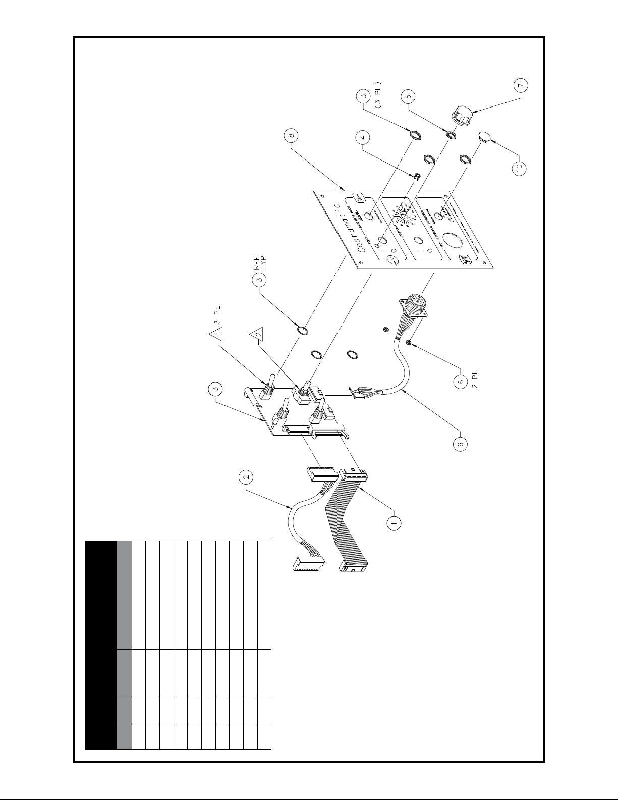
003-2110 Cobramatic Front Panel Assembly
003-2110b
Front Panel Assy.
1 1 003-1332 Assy cbl rbn 26c
2 1 003-1631 Cable power assy
No. Qty. Part No. Description
3 1 003-2024 Assy pcb fr pnl cb 1 110V
4 1 301-0023 Grommet panel mount
5 1 341-0050 Nut 3/8 - 32 st
6 2 345-0004 Nut hex lock 4-40
7 1 401-0012 Knob Ø1.0 blk
8 1 436-0144 SS pnl fr Cobramatic
9 1 003-1642 Assy con 7p “w” cb
Cobramatic® Owner’s Manual - page 17
10 1 351-0835 Snap btn Ø1/2 hold blk
Page 25
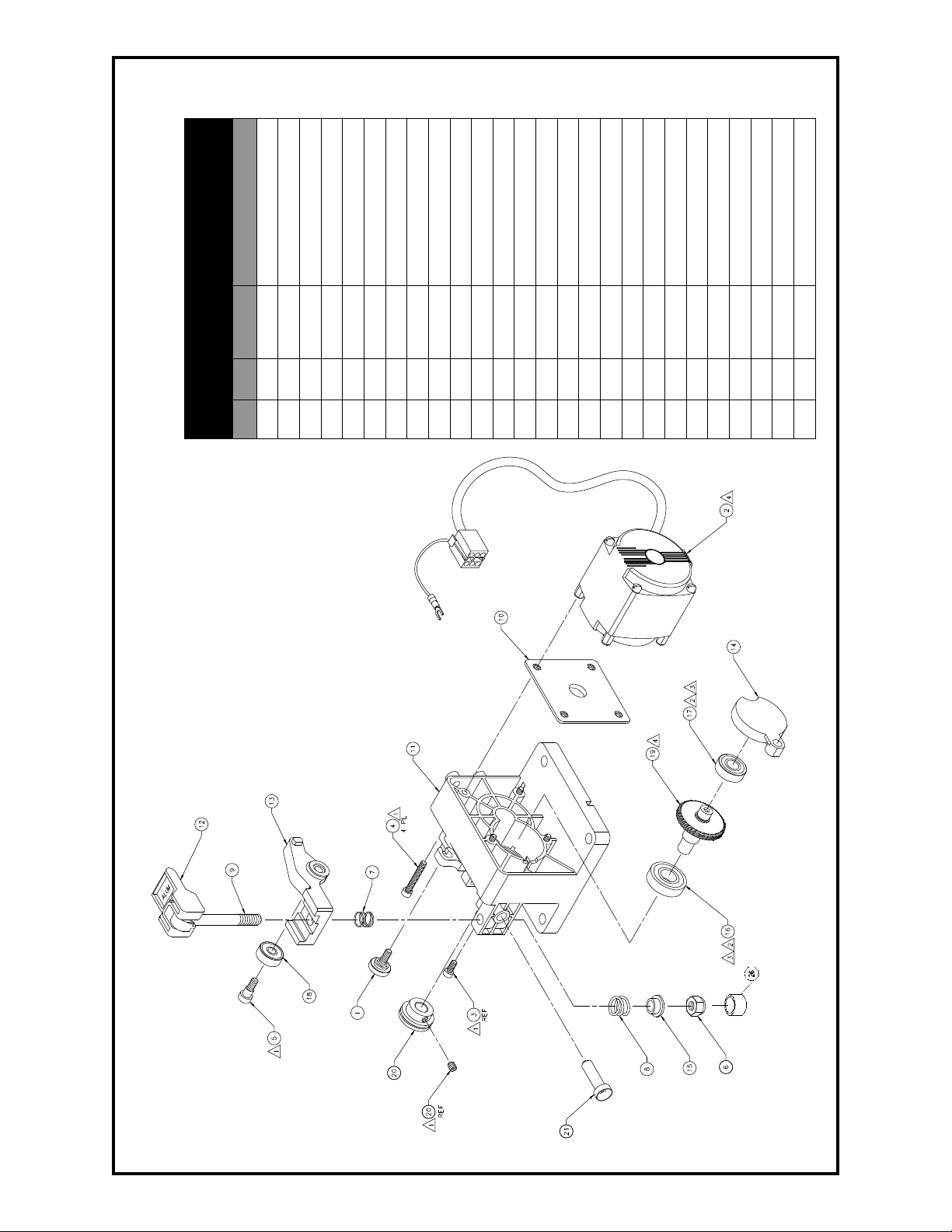
003-2078 Cobramatic Slave Motor Assembly
003-2078
Slave Motor Assy.
1 1 003-0176 Assy knob conduit
2 1 003-2069 Assy torque motor 115V
3 2 328-0024 Scr shc 8-32 X 3/8 stl
4 4 328-0259 Scr shc 8-32 X 1-1/8 stl
5 1 330-0258 Scr Shldr 1/4 X 1/4 X 10/24
6 1 345-0018 Nut Lock 5/16-18
7 1 419-0085 Spring comp 1/32 X OD .40
8 1 419-0211 Spring comp OD 5/8 X 1/16
9 1 431-1576 Bolt swing mod
11 1 437-0230 Housing slave motor mold
10 1 435-01582 Plate locate slave motor
12 1 437-0231 Handle mold slave motor
13 1 437-0232 Arm idler mold slave motor
14 1 437-0245 Cap bearing mold
15 1 437-0254 Sleeve spring
16 1 501-0118 Bearing 1.125 X .50 X .31
17 1 501-0156 Bearing, .875 X .38 X .28
No. Qty. Part No. Description
18 1 501-0207 Bearing idler roll
19 1 507-0130 Shaft gear
20 1 511-0206 Drive roll
21 1 753-0210 Guide wire inlet
22 A/P 823-0043 Loctite threadlocking
23 A/P 835-0001 Grease mobliux 2
24 A/P 823-0051 Loctite retaining compound
25 Ref 031-0167 Test procedure
26 1 751-0018 Cap .5 X .5 lg vinyl black
Cobramatic® Owner’s Manual - page 18
Page 26
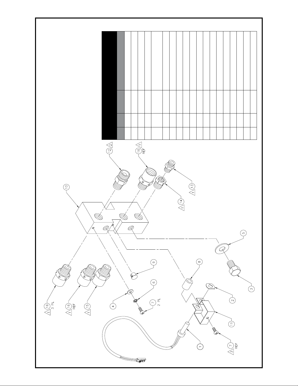
003-2063 Cobramatic Power Block Assembly
Washer fl at 0.391 ID X
0.875OD
003-2063
Power Block Assy.
1 1 003-1243 Assy sensor Posa-Start
2 1 313-0021 Stud receiver push-on
3 1 329-0054 Scr hex 3/8-16 X 5/8
4 1 331-0002 Washer fl at #6 st.
5 1 331-0777
6 1 333-0252 Wshr lk star-in #6 st.
7 2 336-0005 Scr pn ph 6-32 x .375 stl
8 1 342-0395 Spacer current sensor
9 1 351-0066 Plug hole Ø5/16
11 1 435-3038 Bracket current sensor
No. Qty. Part No. Description
10 1 431-1612 Block power cb2k
12 1 753-0112 Ftg 1/4npt male to 5/8-18 male
13 1 753-0114 Aptr 1/8nt X 1/8nps
14 1 753-0115 Bush 1/4npt male to 1/8mpt fem
15 1 753-0466 Aptr 1/4npt male to 5/8-18 fem
16 3 753-0475 Aptr 1/4npt m to 5/8-18 fem lh
17 A/R 823-0029 Noalox pipe thread sealant
18 A/R 823-0043 Loctite 242 threadlock
19 A/R 823-0044 Loctite pipe thread sealant
Cobramatic® Owner’s Manual - page 19
Page 27
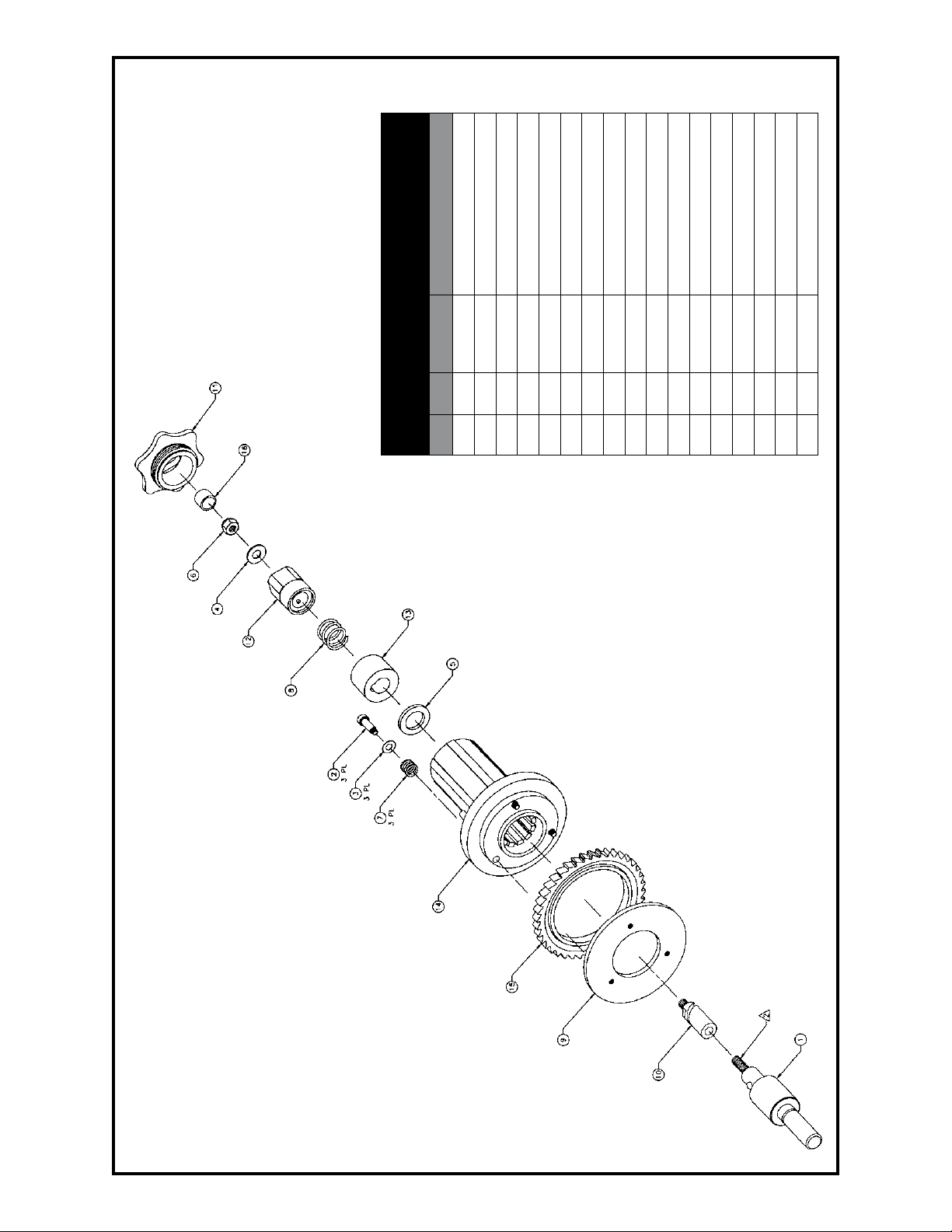
003-2146 Cobramatic Spindle Brake Assembly
003-2146
Spindle Brake Assy.
1 1 003-2139 Assy bearing spindle
2 3 330-3063 Scr shldr mod .25 X .63 10-14
3 3 331-0063 Wshr fl t .355 X .505
4 1 331-0095 Wshr fl t 11/32 X 3/4 sst
5 1 331-0313 Wshr leather .75 ID X .125 thk
6 1 345-0018 Nut hex lock 5/16-18 st
7 3 419-0059 spg comp .468 X .437 X .056
8 1 419-0095 Spg comp .85 X .69 X .75
9 1 431-1266 Plate back-up ring
No. Qty. Part No. Description
10 1 431-3726 Adapter spiral spindle
11 1 437-0258 Retainer spool spindle
12 1 437-0259 Knob tension spindle
13 1 437-0645 Spacer spindle
14 1 437-0645 Spindle
15 1 723-0059 Disk ratchet brake
16 1 751-0018 Cap .5 X .5 lg vinyl black
17 A/R 823-0049 Thread locking permanent
Cobramatic® Owner’s Manual - page 20
Page 28
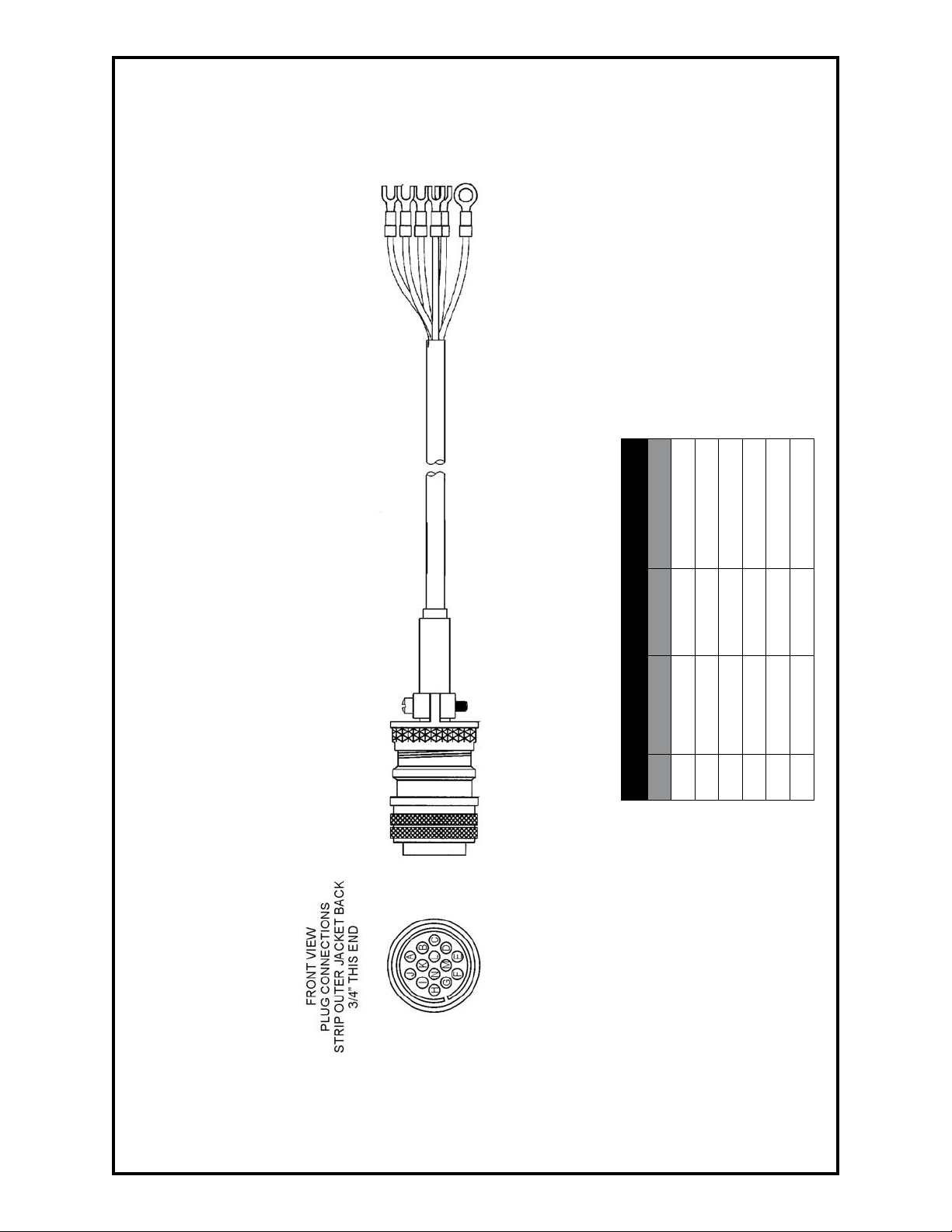
005-0608 8ft., 115 VAC Lincoln Interface Control Cable
005-0659 25ft., 115 VAC Lincoln Interface Control Cable
Wire List
H Blue J6-2 PosaStart
Pin Wire Color Terminal Function
J White J5-1 115V Neutral
A Black J5-2 115V Hot
C Red J6-3 Closing Contact
D Orange J6-4 Closing Contact
B Green Chassis Ground
Cobramatic® Owner’s Manual - page 21
Page 29
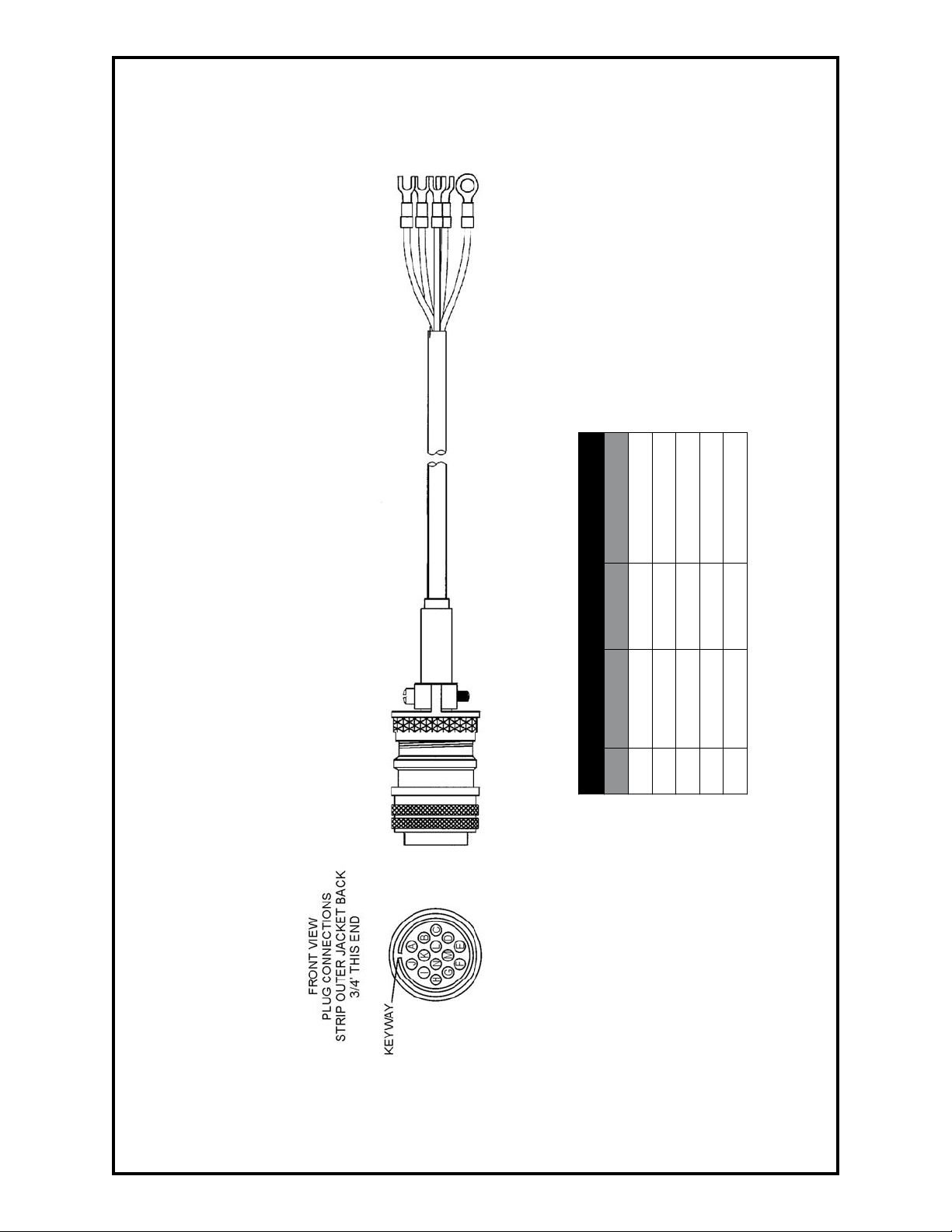
005-0316 8ft., 115 VAC Miller Interface Control Cable
005-0658 25ft., 115 VAC Miller Interface Control Cable
Wire List
A Red J6-3 Closing Contact
Pin Wire Color Terminal Function
B Orange J6-4 Closing Contact
I Black J5-2 115V Hot
G White J5-1 115V Neutral
K Green Chassis Ground
NOTE: Posa Start lead from Cobramatic®
must be attached to working (welding)
ground.
Cobramatic® Owner’s Manual - page 22
Page 30
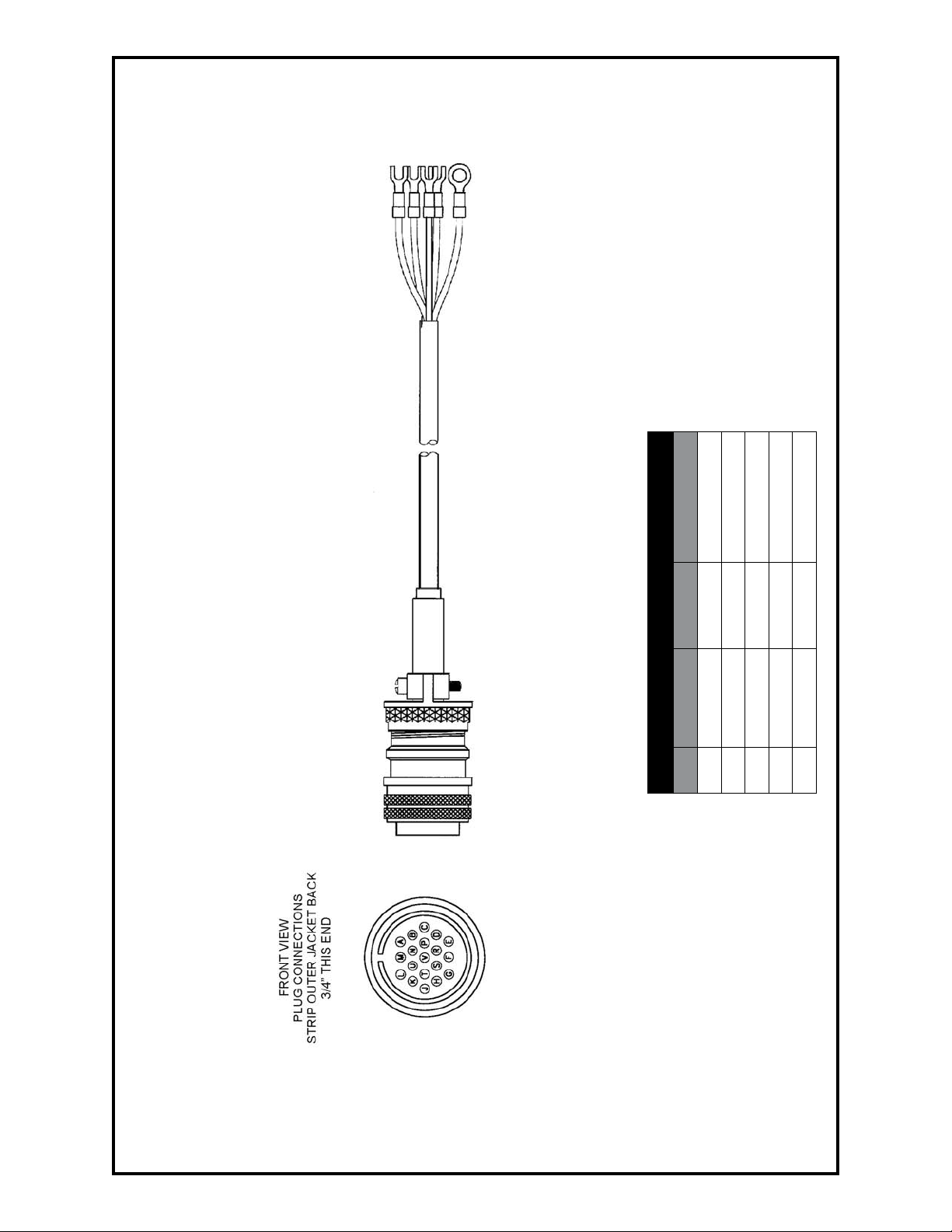
005-0614 8ft Interface Cable for Thermal Arc 19-Pin, 115VAC
Wire List
A Red J6-3 Closing Contact
Pin Wire Color Terminal Function
J6-4 Closing Contact
B Orange
E Black J5-2 115V Hot
G Green Chassis Ground
F White J5-1 115V Neutral
Cobramatic® Owner’s Manual - page 23
Page 31
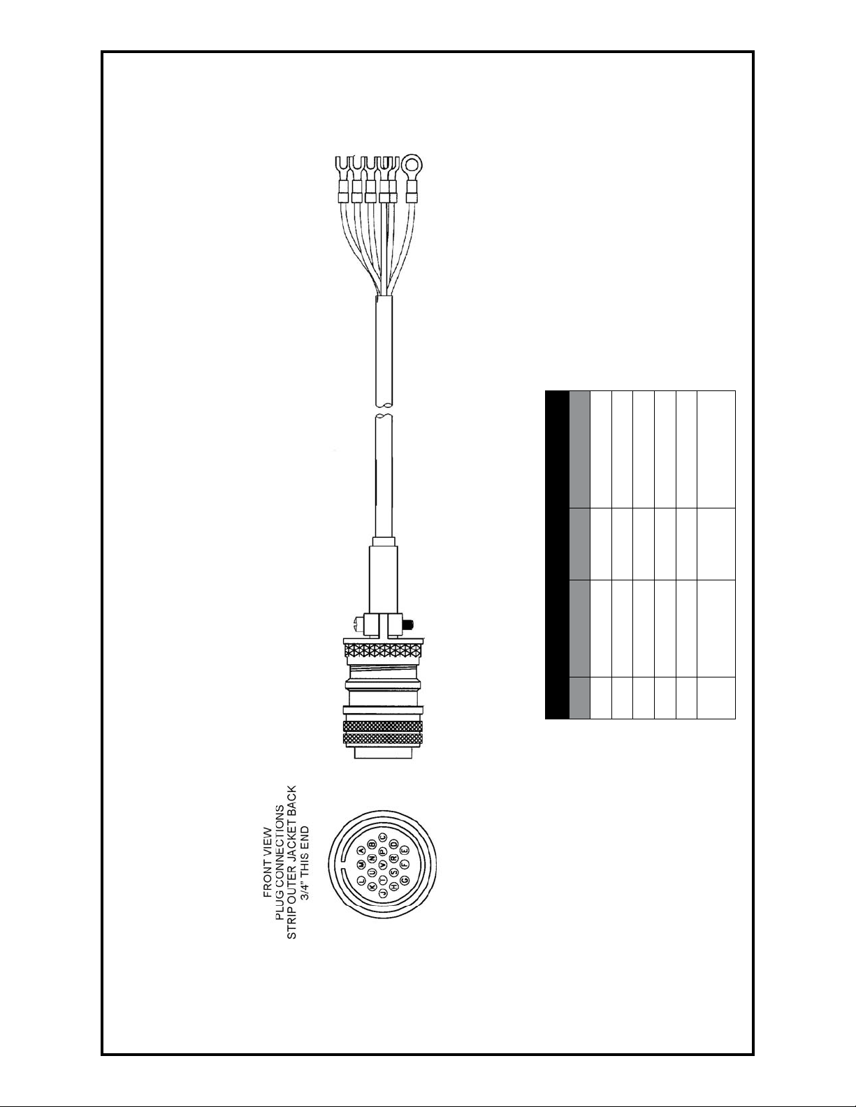
005-0614 8ft Interface Cable for ESAB 19-Pin, 115VAC
Wire List
A Black J5-2 115V Hot
Pin Wire Color Terminal Function
J5-1 115V Neutral
B White
D Green Chassis Ground
M Blue J6-2 PosaStart
J6-3 Closing Contact
White w/
Black or Red
V
U Orange J6-4 Closing Contact
Cobramatic® Owner’s Manual - page 24
Page 32
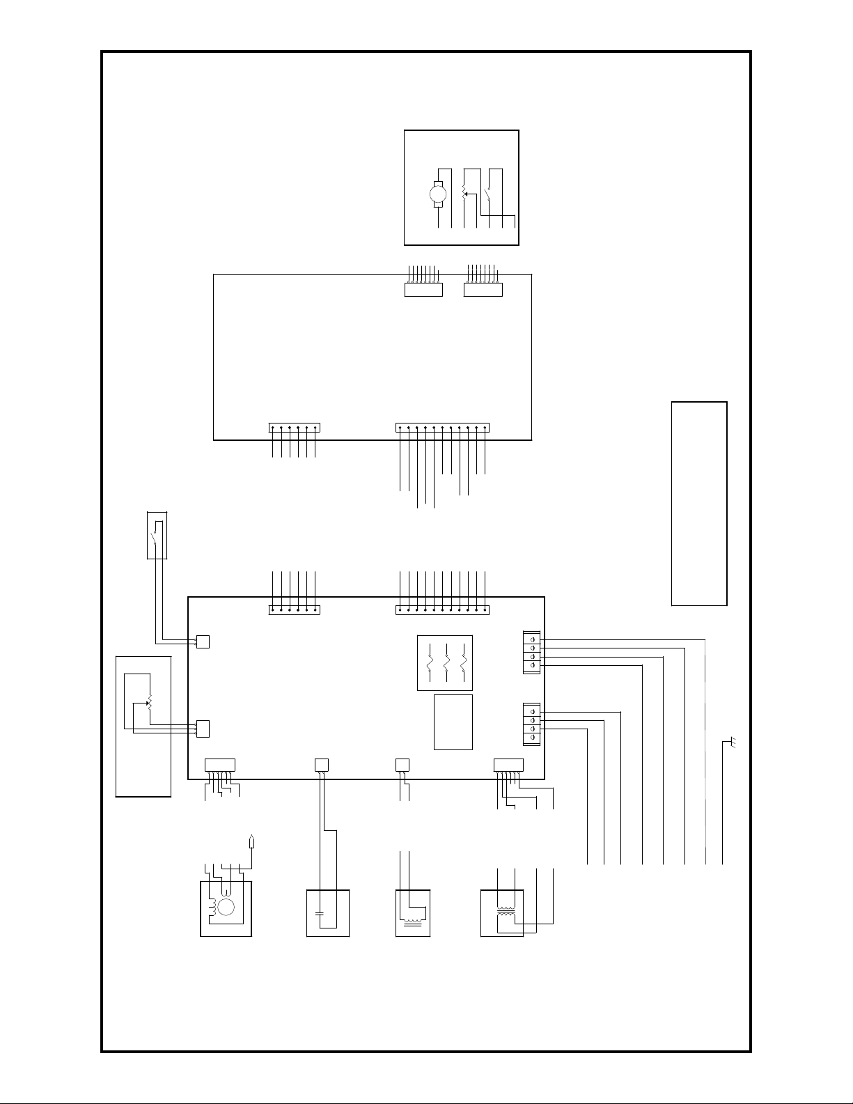
(+)
(-)
TORCH TRIGGER 27V (RTN)
RELAY CLIP
P/N 003-1628 (115V)
P/N 003-2024 (115V)
J4-1 AC (H)
071- 0387
A
COBRAMATIC I - 115V / 42V BLOCK DIAG
RAM
M. K. PRODUCTS INC.
C
1
1
Thursday, August 15, 2002
Title
Size
Document Number
Re
Date:
Sheet
of
1234561212345
6
123456781234567
8
1
2
F1
4A
27VAC
F2
AC IN
F3
AC IN
REMOTE POT
5K
(+
)
071-0387 Cobramatic Block Diagram
TORCH
MOTOR
TORCH
DATE APPR
12/00
08/02
MS "W"
003-1642
ABCDEFG
PRN 3231
DCN 12958
AMPHENOL CONNECTOR
TORCH "W" CLK
ABCDEFG
POT
CW 5K
ABCDEFG
TORCH
TRIGGER
A
-
REV P/ZONE DESCRIPTION / DCN
1
MAIN SWITCH AC IN (N), BRN
P/N 003-1243
(AT POWER BLOCK)
WELDING CURRENT DETECTOR
2
1
1
CABLE 003-1631
1
J1J14
FRONT PANEL
COBRAMATIC I
J1
MAIN SWITCH AC OUT (H), ORN
TORQUE SWITCH (RETURN), GRN
TORQUE SWITCH (SOURCE), BLU
MAIN SWITCH AC IN (N), YEL
MAIN SWITCH AC OUT (N), RED
J3
1
P/N 003-2001 (42V)
1
POSASTART (SOURCE)
POSASTART (RETURN)
TORCH POT CW
CABLE 003-1332
1
1
J3
J2
TORCH POT CCW
TORCH POT WIPER
TORCH MOTOR (+)
TORCH MOTOR (-)
TORCH TRIGGER 27V (SRC)
J2
J4
POWER INDICATOR LED (H)
POWER INDICATOR LED (N)
SCH 071-0270
SCH 071-0367 (42V)
SCH 071-0370 (115V)
J5J6
- MOVE WIRE FROM J6-4 TO J5-4
- MOVE WIRE FROM J6-3 TO J5-3
THIS DOCUMENT IS THE PROPERTY OF MK PRODUCTS INC.
IT MAY NOT BE COPIED, REPRINTED OR DISCLOSED TO A THIRD
PARTY, EITHER WHOLLY OR IN PART, OR USED AS A BASIS FOR
MANUFACTURE WITHOUT THE PRIOR WRITTEN CONSENT OF
IF AN AC VOLTAGE CONTACTOR SIGNAL IS REQUIRED
NOTE:
MK PRODUCTS INC.
W
CW
3
2
1
11
(OPTIONAL)
J7-3 WELD VOLT RED
J7-1 AC (H) RED
J7-2 AC (H) BLK
J7-4 AC (N) WHT
J7-6 AC (N) BLU
SLAVE MOTOR
P/N 003-2060 (42V)
P/N 003-2078 (115V)
J7
1
TO POWER BLOCK
P/N 003-1798
EXT CAP (42V ONLY)
MAIN BOARD
COBRAMATIC I
P/N 003-1721 (42V)
J12
1
J4-2 AC (N)
P/N 003-2095 (42V)
BRAKE SOLENOID
P/N 003-2096 (115V)
P/N 157-0022
RELAY K2
J4
TRANSFORMER
P/N 157-0023
1
27VAC (COM) RED
P/N 003-0773 (115V)
P/N 003-1723 (42V)
Cobramatic® Owner’s Manual - page 25
1234 1234
J8
27VAC (HOT) RED
AC (HOT) BLACK
AC (COM) BLACK
WHITE
BLACK
HOT - BLACK
NEUTRAL - WHITE
WORK GROUND (BLK)
CLOSING
POSA START
CONNECTIONS
AC LINE IN
CONTACTOR
GREEN
HOT - BLACK
NEUTRAL - WHITE
CONTACTOR
AC VOLTAGE
SAFETY WIRE
Page 33
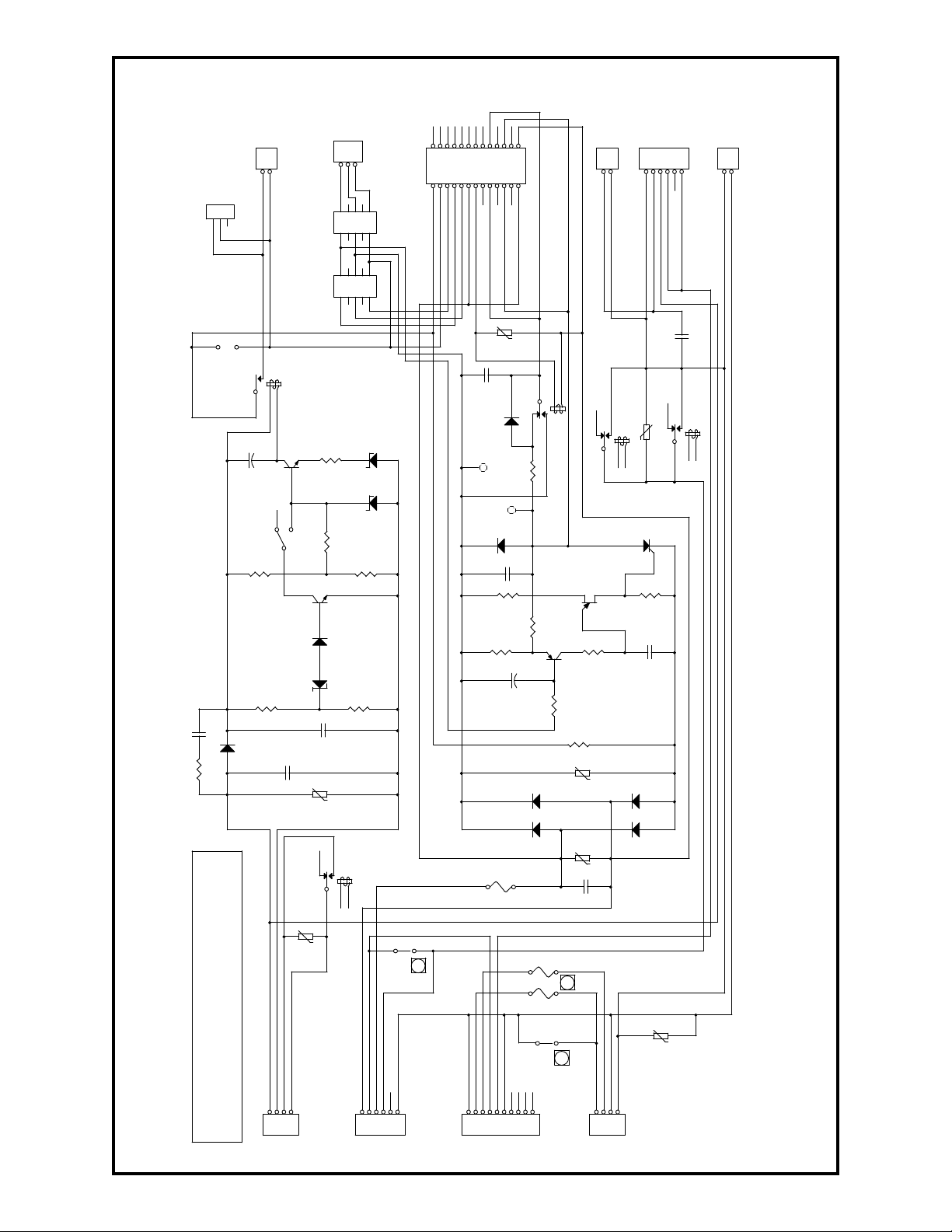
071-0270 Cobramatic Main PC Board
TORCH MOTOR (-)
SW. TORQUE OUT
MAIN
SW.
TERMINAL BLOCK
6
TERMINAL BLOCK
5
Q22N5655
R8
3.
3K
R9
56
0
R102.2KQ3
2N
4249
R1
1
5.
6K
R1
3
22
1/2W
R1210
0
JP
3
D5
1N
4731
4.3V
F1
4A
R1
4
2.7 1W
S1
D2
1N
4731
4.3V
R6
15
01/2W
JP
5
123
+++
F2
F3
K2
B
10
2
6
1413D1
0
D1
1Q5MC
R
218-6
Q4
2N
2646
D7
D9
D8
D6
K2D
12
4
8
14
13
R7
10K
JP
2
C5
60
0
.01
u
C8
.01
u
600
V
C9
.01u600
V
C2
200V
.047
u
C7
.047
u
C10250V3.3
u
J3
123456789
10
J4
BRA
KE SOLENOID
1
2
J6
123
4J5123
4
J12
EXT
CAP
1
2
J7
SLAVE MOTOR
12345
6
J8
TRANSF
ORMER
12345
6
K2
A
RELAY 4PD
T
9
1
5
14
13K1RELAY
5V
K2C
11
3
7
1314RV1
130V
RV5
130
V
RV6
130V
RV7
130V
RV2
56V
RV3
56V
RV4
56V
TP1
TP2R13K
C1
200V.01
u
R2
68K
D1
HEP170
D3
HEP170
Q1
2N
4410
D4
1N
5236B
7.
5V
R4
6.8
K 1/2W
JP4AT2
12345
678910
+++++
+++++
J14
CABINET
POT
123
JP4AT3
1234511121314
15
+++++++++
+
J2
12345678910111213141516171819202122232425
26
JP1
PO
SA
BY
PASS
R1
5
22
1/2W
J1
CURRENT
SENSOR
1
2
C111KV0.00
5u
C6
10
u
C4
10
u
R5
6.8
K 1/2W
R3
68K
W
CCW
CW
TO COBRA I
FRONT PANEL
OPERATION
JUMPER @ JP4AT2
FOR CABINET POT
1
7
2
6
+
CV
CC
CABINET
TORCH
POSA START (OUT)
POSA START (IN)
TORCH POT CW
TORCH POT WIPPER
TORCH POT CCW
TRIGGER 27VH (OUT)
TRIGGER 27VH (IN)
TORCH MOTOR (+)
27VAC LED (+)
TORCH MOTOR (+)
+
27VAC LED (-)
TORCH MOTOR (-)
MOTOR AC (H)
CAP AC (H)
MOTOR AC (L)
MOTOR AC (L)
WELD VOLT (+)
SOL AC (L)
SOL AC (H)
C.CONTACT
C.CONTACT
WELD VOLT (+)
WELD VOLT (-)
THIS DOCUMENT IS THE PROPERTY OF MK PRODUCTS INC.
IT MAY NOT BE COPIED, REPRINTED OR DISCLOSED TO A THIRD
PARTY, EITHER WHOLLY OR IN PART, OR USED AS A BASIS FOR
MANUFACTURE WITHOUT THE PRIOR WRITTEN CONSENT OF
MK PRODUCTS INC.
1
XFMR AC IN (H)
XFMR AC (L)
XFMR AC OUT (H)
27V (L)
27V (H)
SW. AC (H) OUT
SW. AC (H) IN
SW. AC (L) OUT
SW. AC (L) IN
SW. TORQUE IN
Cobramatic® Owner’s Manual - page 26
1
1
CONTACT AC (H)
CONTACT AC (L)
AC IN (L)
AC IN (H)
1
Page 34
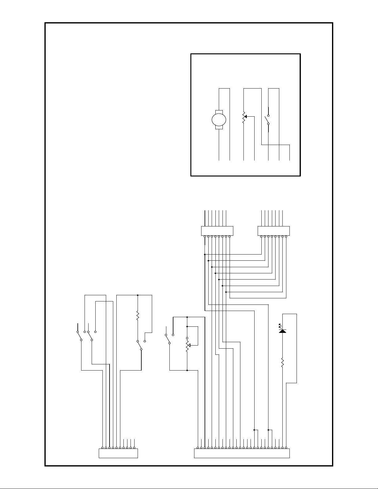
071-0370 Cobramatic Torch Connections
P
D
D
K
J1
P10
123456789
10
J2
P26
1
2345678
9
1011121314151617181920212223242526
J3
P8
1234567
8
J4
P8
1234567
8
D1
GREEN
R2
100K
SW3
SW SPDT
R1
400 OHM
8W
SW2
SW SPDT
SW1A
213
SW1B
546
R3
2.7K/1/2W
R?
PO
T
C
01/98
PRN 2886-
DCN 11559 12/98
DCN 12472B 12/00
REVISIONS
P/ZONE DESCRIPTION/DCN # DATE AP
A
REV.
MOTOR
TORCH
POT
TORCH
TORCH
TRIGGER
(+) (-)
TORCH "W" CLOCK
A
B
C
D
E
F
ABCDEFG
ABCDEFG
G
FOR ALL
OTHER
FOR 0.030 - 0.035
CW
TORQUE
TORQUE
115VAC (N)
115VAC (N)
115VAC (H)
115VAC (H)
POSA START
POSA START
TORCH POT CW
TORCH POT WIPER
TORCH POT CCW
TORCH TRIGGER 27VAC (H)
TORCH TRIGGER 27VAC (H)
TORCH MOTOR (+)
TORCH MOTOR (-)
POWER INDICATOR LED (H)
POWER INDICATOR LED (N)
Cobramatic® Owner’s Manual - page 27
Page 35
MK WARRANTY REPAIR STATIONS
ALABAMA
AIRGAS - SOUTH, INC.
Birmingham, AL
205/251-6835
KIBRO, INC.
Theodore, AL
251/653-4672
ALASKA
RNR, INC. dba
Rubey Engine & Electric
Anchorage, AK
907/336-5152
ARIZONA
PRAXAIR DISTRIBUTION, INC.
Phoenix, AZ
602/269-2151
for most up-to-date list, please visit www.mkproducts.com
for MK Products as of 8/29/02
DIXIE WELDING SUPPLY
Attalla, AL
256/538-6157
WELDING ENGINEERING
SUPPLY CO.
Prichard, AL
334/457-8681
ALLSTATE ELECTRIC MOTOR CO.
Phoenix, AZ
602/233-0500
INDUSTRIAL WELDING SERVICES
Quinton, AL
205/674-3258
WELDING MACHINE HOSPITAL
Montgomery , AL
334/832-9353
ARKANSAS
APPLIED SERVICES, INC.
Benton, AR
501/860-6464
CALIFORNIA
ADVANCED WELDER REPAIR
Commerce, CA
323/263-7383
ARC PRODUCTS
San Diego, CA
619/628-1022
CAL-WELD SUPPLY
Fresno, CA
209/445-0131
FRESNO OXYGEN
Fresno, CA
559/233-6684
PRAXAIR DISTRIBUTION
(ARC RENTS)
Signal Hill, CA
562/989-3212
RED-D-ARC, INC.
Carson, CA
310/233-3327
SWEINHART ELECTRIC CO.,
INC.
Long Beach, CA
714/521-9100
ARKANSAS WELDING IND’L
SUPPLY
Hot Springs, AR
501/321-9922
EL DORADO WELDING &
INDUSTRIAL SUPPLY
El Dorado, AR
870/863-4088
AIRGAS - WEST, INC.
Gardena, CA
310/523-9355
ARCO WELDER REPAIR
Santa Fe Springs, CA
562/921-5240
DELTA-TECH
Sun Valley, CA
818/767-4234
INDUSTRIAL WELDER REPAIR
LaPuente, CA
626/961-7643
PRAXAIR DISTRIBUTION, INC.
Bakers eld, CA
661/321-9922
SIMS-ORANGE WELDING SUPPLY
Santa Ana, CA
714/549-9393
ALL PHASE WELDER REPAIR &
CONSULTING
Sacramento, CA
916/331-0595
ARK WELDER REPAIR
Fresno, CA
559/292-4714
EMCO-EAST WELD’R REPAIR
Concord, CA
925/798-4411
NESCO WELDING SUPPLY
Fontana, CA
909/427-9670
R. J. KATES
San Diego, CA
619/565-6960
SOUTHWEST WELDER REPAIR
Fontana, CA
909/357-1661
Cobramatic® Owner’s Manual - page 28
Page 36
MK WARRANTY REPAIR STATIONS
for most up-to-date list, please visit www.mkproducts.com
for MK Products as of 8/29/02
COLORADO
AIRGAS - INTERMOUNTAIN,
INC.
Colorado Springs, CO
719/473-1947
CONNECTICUT
ABCO WELDING & INDUSTRIAL
SUPPLY CO.
Waterford, CT
800/962-0285
DELAWARE
KEEN COMPRESSED GAS
New Castle, DE
302/594-4555
FLORIDA
A & I SPECIALTIES
Lehigh Acres, FL
941/368-7435
AMVEL CORPORATION
Miami, FL
305/592-5678
HOLOX
Ocala, FL
352/351-4417
SMITTY’S WELDER SERVICE
West Palm Beach, FL
561/845-1224
TRI-TECH
Sarasota, FL
941/758-3825
GEORGIA
B&W INDUSTRIAL SERVICES
Augusta, GA
706/738-8722
HAWAII
DC ELECTRIC, INC.
Aiea, HI
808/483-8900
IDAHO
NORCO
Boise, ID
208/336-1643
WELDERS & EQUIP. SVC. & TESTING
Littleton, CO
303/932-8755
WESTERN SLOPE WELDER
REPAIR
Grand Junction, CO
970/243-9616
TECH AIR
Milford, CT
203/783-1834
AAA GENERATOR & PUMP
Ft. Myers, FL
941/332-1136
ELECTRICAL WELDERS SERVICE
Orlando, FL
407/999-5214
J.K. CIRCUIT TECHNOLOGY
Boynton Beach, FL
561/733-7859
TRI-GAS
Miami, FL
305/592-3180
V.A. ELECTRICAL MOTORS
CENTER, INC.
Hialeah, FL
305/825-3327
Mc CULLOUGH ELEC. MOTOR SVC.
Atlanta, GA
404/688-5251
ACTION WELDING SUPPLY
Jacksonville, FL
904/786-2254
HAUN SYSTEMS REPAIR, INC.
Winter Park, FL
407/681-6064
ROPER ELECTRIC MOTOR SERVICE
Panama City, FL
850/769-6643
TRI-STATE SALES & LEASING
Lake City, FL
904/397-3340
ROSSITER ELECTRIC
Idaho Falls, ID
208/529-3665
Cobramatic® Owner’s Manual - page 29
Page 37
MK WARRANTY REPAIR STATIONS
for most up-to-date list, please visit www.mkproducts.com
for MK Products as of 8/29/02
ILLINOIS
CMS ELECTROMECHANICAL
SERVICES, INC.
Galesburg, IL
309/342-4125 – 888/9643526
RELIABLE EQUIPMENT REPAIR
Hamel, IL
618/633-5000
INDIANA
AGA GAS, INC.
Hammond, IN
219/989-9030
COX EQUIPMENT COMPANY
Indianapolis, IN
317/241-8881
MODERN SUPPLY CO., INC.
Evansville, IN
812/425-9353
IOWA
AIRGAS NORTH CENTRAL
Des Moines, IA
515/266-1111
SUPERIOR WELDING SUPPLY
Waterloo, IA
319/236-9660
KANSAS
AEROFORM CORPORATION
Co eyville, KS
620/251-1430
KENTUCKY
GENERAL WELDING PRODUCTS
Louisville, KY
502/635-5218
LOUISIANA
RED BALL OXYGEN CO.
Shreveport, LA
318/425-3211
FRED ARMS ELECTRIC MOTOR
REPAIR
Stone Park, IL
708/343-6262
ROCKFORD INDUSTRIAL WELDING
SUPPLY
Rockford, IL
815/226-1900
INDUSTRIAL WELDER REBUILDERS
Alsip, IL
708/371-5688
AIRGAS - MID AMERICA, INC.
Evansville, IN
800/424-8905
EVANSVILLE ARMATURE, INC.
Evansville, IN
812/428-9034
PRAXAIR DISTRIBUTION, INC.
Speedway, IN
317/481-4550
B & H ELECTRIC
Seymour, IN
812/522-5607
HARRISON ELECTRIC, INC.
Michigan City, IN
219/879-0444
SUTTON-GARTEN COMPANY
Indianapolis, IN
317/264-3236
CEDAR RAPIDS WELDING SUPPLY
Cedar Rapids, IA
319/365-1466
WRIGHT WELDING SUPPLY
Ft. Dodge, IA
515/576-0640
ELECTRICAL ENGRG. & EQUIPMENT
Des Moines, IA
515/266-8890
KANOX
Hutchinson, KS
316/665-5551
RED-D-ARC
Lexington, KY
800/245-3660
WELDING EQUIPMENT
Louisville, KY
502/636-0545
WELDERS EQUIPMENT CO.
Broussard, LA
337/837-5701
MARYLAND
CCM MECH/ELEC REPAIR
SERVICE
Owings, MD
301/855-7508
Cobramatic® Owner’s Manual - page 30
Page 38
MK WARRANTY REPAIR STATIONS
for most up-to-date list, please visit www.mkproducts.com
for MK Products as of 8/29/02
MASSACHUSETTS
NEW YORK
AIMTEK WELDING SUPPLY
DELO WELDING SUPPLY
Auburn, MA
Syracuse, NY
508/832-5035
315/478-2188
MICHIGAN
ANN ARBOR WLDG SUPPLY CO.
Ypsilanti, MI
734/572-0444
GREAT LAKES EQUIPMENT
Clare, MI
517/386-4630
SIMPKINS ELECTRICAL SVC.
Michigan Center, MI
517/764-7766
WESAR COMPANY
Three Rivers, MI
616/483-9125
MINNESOTA
AIRGAS – NORTH CENTRAL
Albert Lea, MN
507/373-2411
OXYGEN SERVICE CO.
St. Paul, MN
612/644-7273
MISSOURI
CEE-KAY SUPPLY, INC.
St. Louis, MO
324/644-3500
MISSISSIPPI
NORDAN SMITH WELDING
SUPPLY
Hattiesburg, MS
601/545-1800
NEVADA
SIERRA WELDING SUPPLY CO.
Sparks, NV
775/359-0542
NEW HAMPSHIRE
WELDING SYSTEMS SVC.
Raymond, NH
603/895-4700
NEW JERSEY
INDUSTRIAL ELECTRIC SERVICE CO.
Hawthorne, NJ
973/423-1212
DYNAMIC WELD’G & REPAIR
Bayshore, NY
631/643-1308
HAUN WELDING SUPPLY
Syracuse, NY
315/463-5241
APEX WELDING GASES & SUPPLY
Muskegon Heights, MI
616/722-3185
HAMILTON ELECTRIC CO.
Saginaw, MI
517/799-6291
SOUTHPARK WELDING
Marysville, MI
810/364-6521
AUTOMATIC WELD
Midland, MI
517/496-9245
SAGINAW WELDING SUPPLY CO.
Saginaw, MI
517/793-9696
WELDING METALS, INC.
Madison Heights, MI
248/585-0480
CAPITOL CITY WELDING SUPPLY
St. Paul, MN
651/224-4843
MINNEAPOLIS OXYGEN CO.
Minneapolis, MN
612/588-8855
P.G. WALKER
Spring eld, MO
417/862-1745
ROD’S SERVICE, INC.
St. Louis, MO
314/721-6000
3D SUPPLIES, INC.
Jackson, MS
601/353-3330
Cobramatic® Owner’s Manual - page 31
Page 39
MK WARRANTY REPAIR STATIONS
JACKSON WELDING SUPPLY
Rochester, NY
585/235-2920
NORTH CAROLINA
ADAMS WELDER REPAIR &
ELECTRICAL SERVICE, INC.
Nashville, NC
252/459-1960
MACHINE & WELDING SUPPLY
CO.
Dunn, NC
910/892-4016
MACHINE AND WELDING
SUPPLY CO.
Winston-Salem, NC
336/723-9651
OHIO
AGA GASES, INC.
Lima, OH
419/228-2828
ARC EQUIPMENT COMPANY
Struthers, OH
333/750-9353
BIG RIVER ELECTRIC
Gallipolis, OH
740/446-4360
MAINTENANCE UNLTD. & TOOL
REPAIR
Cincinnati, OH
513/554-1313
RICK’S WELDER REPAIR SERVICE
Eastlake, OH
440/269-1204
VALLEY NATIONAL GASES
Lima, OH
419/228-1008
VOLLMER ELECTRIC CO.
Columbus, OH
614/476-8800
OKLAHOMA
AIRGAS MID-SOUTH
Tulsa, OK
918/582-0885
OKLAHOMA WELDERS SUPPLY
Madill, OK
580/795-5561
for most up-to-date list, please visit www.mkproducts.com
for MK Products as of 8/29/02
HOLOX LTD.
Colfax, NC
336/996-1974
MACHINE AND WELDING SUPPLY
CO.
Greenville, NC
252/752-3089
NATIONAL WELDERS SUPPLY CO.
High Point, NC
910/882-1110
ALBRIGHT WELDING SUPPLY
Wooster, OH
330/264-2021
ARC SERVICES, INC.
Toledo, OH
419/478-6204
CnD MACHINE, INC.
Canton, OH
330/478-8811
O.E. MEYER CO.
Sandusky, OH
419/621-4201
S.D. NOLD, INC.
Lisbon, OH
330/424-3134
VALLEY NATIONAL GASES
Hilliard, OH
614/771-1311
WEILER WELDING CO., INC.
Dayton, OH
937/222-8312
M & L WELDER REPAIR
Asheville, NC
828/250-9353
MACHINE AND WELDING
SUPPLY CO.
Raleigh, NC
919/772-9500
NATIONAL WELDERS SUPPLY
CO.
Charlotte, NC
704/392-7317
ALL ABOUT SERVICE
Wickli e, OH
440/516-0303
BELAIR PRODUCTS, INC.
Akron, OH
330/253-3116
ELECTRIC WELDER REPAIR
Cuyahoga Heights, OH
216/271-5600
OHIO AIR PRODUCTS
Canton, OH
330/821-2771
VALLEY NATIONAL GASES
Cincinnati, OH
513/241-5840
VALLEY NATIONAL GASES
Toledo, OH
419/241-9114
WELDINGHOUSE, INC.
Cleveland, OH
216/524-1955
BILL’S WELDER REPAIR
Oklahoma City, OK
405/232-4799
MUNN SUPPLY
Enid, OK
580/234-4120
OREGON
Cobramatic® Owner’s Manual - page 32
Page 40
MK WARRANTY REPAIR STATIONS
for most up-to-date list, please visit www.mkproducts.com
for MK Products as of 8/29/02
ARC SYSTEMS SERVICES
Central Point, OR
541/665-2676
WELDER SERVICE & REPAIR
Redmond, OR
541/548-8711
PENNSYLVANIA
ALLWELD EQUIPMENT REPAIR
Pittsburgh, PA
412/821-8460
J.A. CUNNINGHAM EQUIPMENT, INC.
Philadelphia, PA
215/426-6650
VALLEY NATIONAL GASES
Pittsburgh, PA
412/281-1835
SOUTH CAROLINA
CAROLINA WELDER SVC.
Lake City, SC
843/687-0413
TENNESSEE
INDUSTRIAL MACHINE
REPAIRS
Rogersville, TN
423/272-8199
QUALITY WELD’G EQUIPMENT
Nashville, TN
615/726-5282
TEXAS
AIRGAS-SOUTHWEST, INC.
Austin, TX
512/835-0202
FT. WORTH WELDERS SUPPLY,
INC.
Ft. Worth, TX
817/332-8696
RITE-WELD SUPPLY, INC
Fort Worth, TX
817/626-8237
UTAH
ARC SERVICES, LLC
West Valley City, UT
801/975-1121
E C COMPANY
dba ELECTRICAL CONSTRUCTION
COMPANY
Portland, OR
800/452-1511
INDUSTRIAL SOURCE
Eugene, OR
541/344-1438
BY DESIGN
Columbia, PA
717/681-9494
JOSEPH PINTO, JR. EQUIPMENT
CO.
E. Lansdowne, PA
610/259-4100
GEOVIC WELDING SUPPLY
Milton, PA
717/742-9377
POWER SOURCE REPAIR CO.,
INC.
Collingdale, PA
610/532-6460
NEXAIR
Memphis, TN
901/523-6821
TRAMCO
Bristol, TN
423/968-4499
NATIONAL RENTAL & REPAIR
Knoxville, TN
423/584-6390
AIRGAS-SOUTHWEST, INC.
Houston, TX
713/462-8027
GPC SERVICES, INC.
San Angelo, TX
915/655-4545
TexAir WELDING SUPPLY
Longview, TX
903/238-9353
DENISON OXYGEN
Denison, TX
903/465-3369
LEKTROTECH, INC.
Greenville, TX
903/454-7146
WELDING MACHINE & TORCH
REPAIR
San Antonio, TX
210/680-8390
C.W. SILVER INDUSTRIAL SERVICE
Salt Lake City, UT
801/531-8888
Cobramatic® Owner’s Manual - page 33
Page 41
MK WARRANTY REPAIR STATIONS
for most up-to-date list, please visit www.mkproducts.com
for MK Products as of 8/29/02
VERMONT
W.J. WELDING EQUIPMENT
REPAIR, INC.
N. Clarendon, VT
802/775-7422
VIRGINIA
AIR PRODUCTS & CHEMICALS,
INC.
Bristol, VA
540/669-3161
N.W. MARTIN CO.
Spring eld, VA
703/644-0120
WASHINGTON
AIRGAS - NORPAC, INC.
Tacoma, WA
253/473-2282
AMERICAN EQUIPMENT SERVICES
Kent, WA
253/395-9947
PACIFIC WELDING SUPPLIES
Tacoma, WA
253/572-5302
WEST VIRGINIA
CARDINAL SALES & SERVICE,
INC.
Clarksburg, WV
304/622-7590
WISCONSIN
INTERSTATE WELDING SALES
CORP.
Appleton, WI
920/734-7173
VALLEY NATIONAL GASES
Milwaukee, WI
414/281-9540
CANADA
ARC WELDERS, INC.
Ashland, VA
804/798-1818
NORFOLK WELDERS SUPPLY
Norfolk, VA
804/622-6571
ARCET EQUIPMENT CO.
Hampton, VA
757/728-9353
AIRGAS – NORPAC, INC.
Vancouver, WA
360/574-5311
HARRIS ELECTRIC, INC.
Seattle, WA
206/782-6668
PRECISION WELDER & ENGINE
REPAIR
Seattle, WA
206/382-6227
A-L WELDING PRODUCTS
Tukwila, WA
425/228-2218
OXARC, INC.
Spokane, WA
509/535-7794
WILLARD C. STARCHER
Spencer, WV
304/927-2520
MOSINEE MACHINE & ELECTRIC
Mosinee, WI
715/693-0858
WELDER REPAIR & SERVICE
Fredonia, WI
262/692-3068
PRAXAIR DISTRIBUTION, INC.
Brook eld, WI
414/938-6365
Cobramatic® Owner’s Manual - page 34
Page 42
MK WARRANTY REPAIR STATIONS
for most up-to-date list, please visit www.mkproducts.com
for MK Products as of 8/29/02
A&A WELDER SERVICES LTD.
Saskatoon, Saskatchewan
306/934-1601
BARRY HAMEL EQUIPMENT
LT D.
Coquitlam, B.C.
604/945-9313
GPR INDUSTRIES 1994 LTD.
Grande Prairie, Alberta
780/532-5900
LADEL LTD.
Quebec
819/376-6577
OZARK ELECTRICAL MARINE
LT D.
St. Johns, Newfoundland
709/726-4554
WELDERS SUPPLY
Winnipeg, Manitoba
204/772-9476
CHINA
PHT Group Company
Beijing, China
86-10-6858 8395
ARC & GENERATOR REPAIR
Garson, Ontario
705/525-2141
D-TECH WELD SERVICES
Regina, Saskatchewan
306/586-9353
HYPERDYNAMICS TECHNOLOGIES
LT D.
Pickering, Ontario
905/683-9938
LeBLANC ELECTRO-TECH, INC.
Boucherville, Quebec
450/449-5244
PEEL ENGINES
Mississauga, Ontario
905/670-1535
WELDERTECH
Calgary, Alberta
403/279-3432
B. HARRIS WELDING SVCS.
Dartmouth, Nova Scotia
902/468-6255
ELECTRO-MÉCANIK, INC.
Sainte-Foy, Quebec
418/683-1724
INDUSTRIAL ELECTRONIC SERVICES
Calgary, Alberta
403/279-3432
M.R.T. REPAIR CENTER, INC.
Montreal, Quebec
514/648-0800
PROMOTECH ÉLECTRIQUE, INC.
Fleurimont, Quebec
819/822-2111
WELDTEC
B.C.
604/545-3886
Cobramatic® Owner’s Manual - page 35
Page 43

THIS PAGE INTENTIONALLY BLANK
Cobramatic® Owner’s Manual - page 36
Page 44
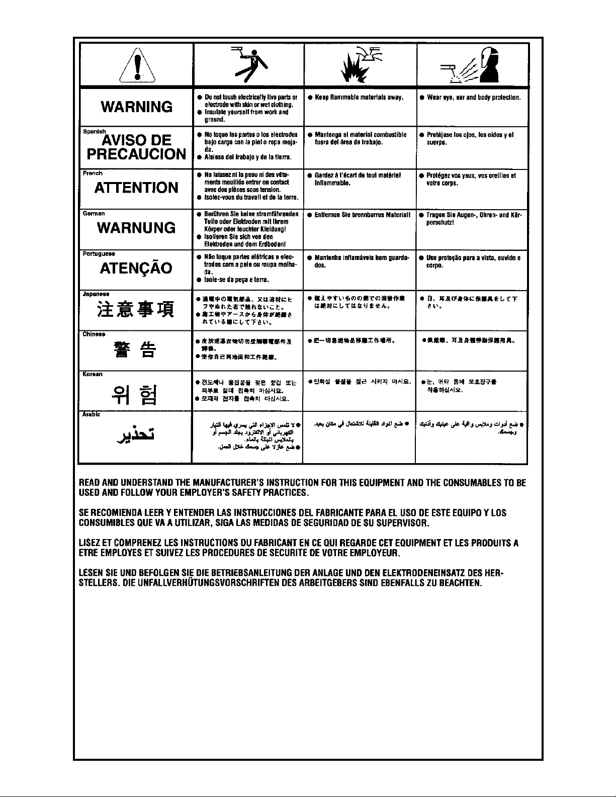
Cobramatic® Owner’s Manual
Page 45
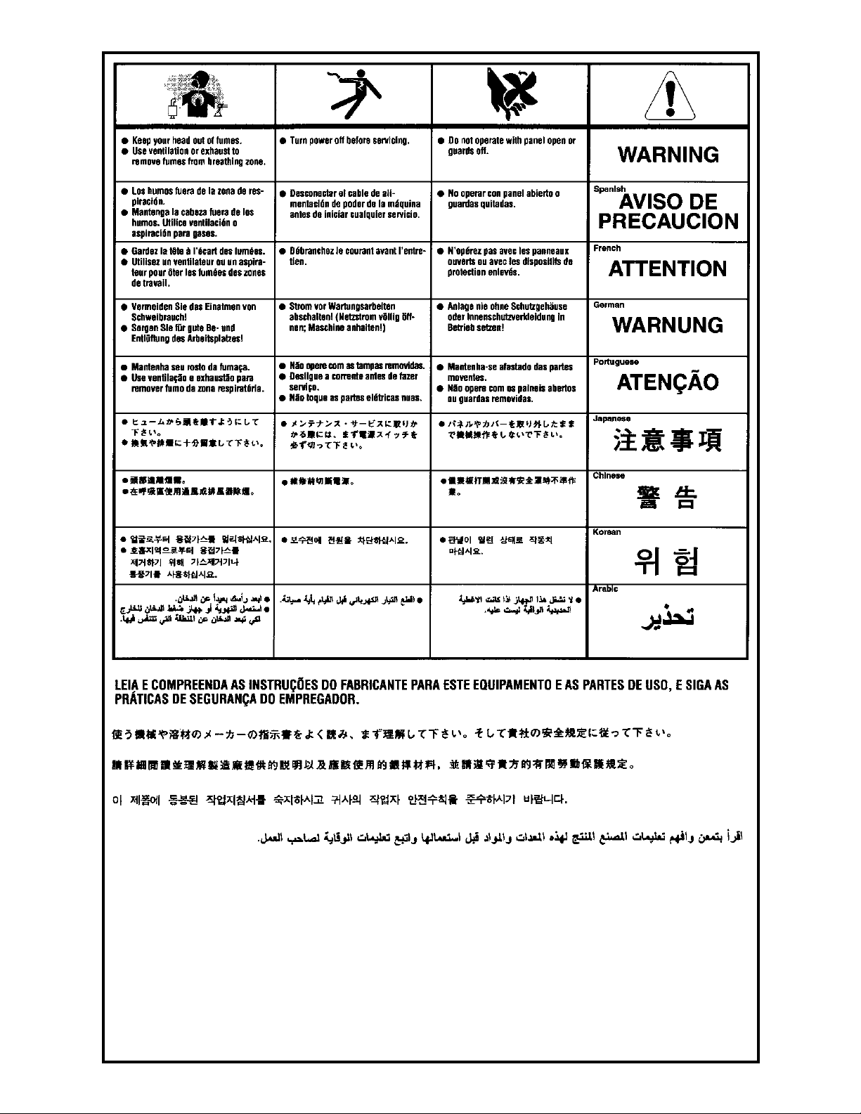
Cobramatic® Owner’s Manual
Page 46

Effective January 1, 2000
This warranty supersedes all previous MK Products warranties and is
exclusive, with no other guarantees or warranties expressed or implied.
LIMITED WARRANTY - MK Products,Inc.,Irvine,California
warrants that all new and unused equipment furnished by
MK Products is free from defect in workmanship and material
as of the time and place of delivery by MK Products. No
warranty is made by MK Products with respect to trade
accessories or other items manufactured by others. Such
trade accessories and other items are sold subject to the
warranties of their respective manufacturers, if any.
MK Products’ warranty does not apply to components having
normal useful life of less than one (1) year, such as relay
points, wire conduit, tungsten, and welding torch parts that
come in contact with the welding wire, including gas cups,
gas cup insulators, and contact tips where failure does not
result from defect in workmanship or material.
In the case of MK Products’ breach of warranty or any other
duty with respect to the quality of any goods, the exclusive
remedies therefore shall be at MK Products’ option:
(1) repair
(2) replacement
(3) where authorized in writing by MK Products, the reasonable cost of repair or replacement at our Irvine, California
plant; or
(4) payment of or credit for the purchase price (less reasonable depreciation based upon actual use) upon return of
the goods at customer’s risk and expense. Upon receipt
of notice of apparent defect or failure, MK Products shall
instruct the claimant on the warranty claim procedures to be
followed.
As a matter of general policy only, MK Products may honor
an original user’s warranty claims on warranted equipment in
the event of failure resulting from a defect within the following
periods from the date of delivery of equipment to the original
user:
1. Torches and Weldheads 1 year
2. All Other Equipment 3 years
3. Repairs 90 days
Classifi cation of any item into the foregoing categories shall
be at the sole discretion of MK Products. Notifi cation of any
failure must be made in writing within 30 days of such failure.
A copy of the invoice showing the date of sale must accompany products returned for warranty repair or replacement.
All equipment returned to MK Products for service must be
properly packaged to guard against damage from shipping.
MK Products will not be responsible for any damages resulting from shipping.
Normal surface transportation charges (both ways) for products returned for warranty repair or replacement will be
borne by MK Products, except for products sold to foreign
markets.
ANY EXPRESS WARRANTY NOT PROVIDED HEREIN
AND ANY IMPLIED WARRANTY, GUARANTY, OR
REPRESENTATION AS TO PERFORMANCE, AND ANY
REMEDY FOR BREACH OF CONTRACT WHICH, BUT
FOR THIS PROVISION, MIGHT ARISE BY IMPLICATION,
OPERATION OF LAW, CUSTOM OF TRADE, OR COURSE
OF DEALING, INCLUDING ANY IMPLIED WARRANTY OF
MERCHANTABILITY OR OF FITNESS FOR PARTICULAR
PURPOSE, WITH RESPECT TO ANY AND ALL
EQUIPMENT FURNISHED BY MK PRODUCTS, IS
EXCLUDED AND DISCLAIMED BY MK PRODUCTS.
EXCEPT AS EXPRESSLY PROVIDED BY MK PRODUCTS
IN WRITING, MK PRODUCTS ARE INTENDED FOR
ULTIMATE PURCHASE BY COMMERCIAL/INDUSTRIAL
USERS AND FOR OPERATION BY PERSONS TRAINED
AND EXPERIENCED IN THE USE AND MAINTENANCE
OF WELDING EQUIPMENT AND NOT FOR CONSUMERS
OR CONSUMER USE. MK PRODUCTS WARRANTIES DO
NOT EXTEND TO, AND NO RE-SELLER IS AUTHORIZED
TO EXTEND MK PRODUCTS’ WARRANTIES TO ANY
CONSUMER.
16882 Armstrong Ave.
Irvine, CA 92606
Tel (949)863-1234
Fax (949)474-1428
[email protected]
Cobramatic® Owner’s Manual
FORM : LW-9MK
DATE : January 1, 2000
Page 47

16882 Armstrong Ave.
Irvine, California 92606
Tel 949.863.1234
Fax 949.474.1428
www.mkproducts.com
 Loading...