

Page 1
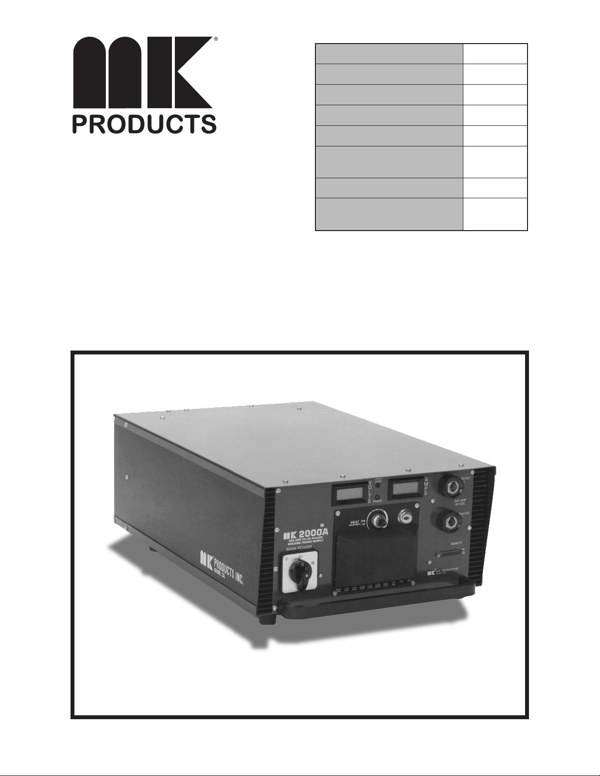
MK2000A Inverter Power Supply
noitpircseDtcudorP noitpircseDtcudorP
noitpircseDtcudorP
noitpircseDtcudorP noitpircseDtcudorP
A0002KM
rebmuNtraPlaunaMKM rebmuNtraPlaunaMKM
rebmuNtraPlaunaMKM
rebmuNtraPlaunaMKM rebmuNtraPlaunaMKM
6220-190
rebmuNmroFKM rebmuNmroFKM
rebmuNmroFKM
rebmuNmroFKM rebmuNmroFKM
A0002KM
rebmuNmroFASWN rebmuNmroFASWN
rebmuNmroFASWN
rebmuNmroFASWN rebmuNmroFASWN
055
rebmuNlaireShtiwevitceffE rebmuNlaireShtiwevitceffE
rebmuNlaireShtiwevitceffE
rebmuNlaireShtiwevitceffE rebmuNlaireShtiwevitceffE
3661
sgnitaRegatloV sgnitaRegatloV
sgnitaRegatloV
sgnitaRegatloV sgnitaRegatloV
.hp3/1V802
.hp3/1V032
etaD.veR/gnitnirP etaD.veR/gnitnirP
etaD.veR/gnitnirP
etaD.veR/gnitnirP etaD.veR/gnitnirP
A1002yluJ
ehtotseilppalaunamsihT ehtotseilppalaunamsihT
ehtotseilppalaunamsihT
ehtotseilppalaunamsihT ehtotseilppalaunamsihT
srebmunledomgniwollof srebmunledomgniwollof
srebmunledomgniwollof
srebmunledomgniwollof srebmunledomgniwollof
100-451
16882 Armstrong Ave., Irvine, CA 92606 TEL (949) 863-1234 FAX (949) 474-1428 www.mkproducts.com
Page 2

SAFETY CONSIDERATIONS
ELECTRIC ARC WELDING EQUIPMENT
CAUTION : READ BEFORE ATTEMPTING INSTALLATION, OPERATION
OR MAINTENANCE OF THIS EQUIPMENT
1-1 INTRODUCTION
This equipment is intended for ultimate
app lication by com mercial/industrial
users and for operation by persons
trained and experienced in the use and
maintenanc e of welding equipment.
Operation should not be under taken
without adequate training in the use of
such equipment. Training is available
from many public and private schools or
similar facilities.
Safe practices in the installation, operation and maintenance of this equipment
requires proper training in the ar t, a
careful study of the information provided
with the equipme nt, and the use of
common sense. Rule s fo r safe use
are generally provided by suppliers of
welding power sources, compressed
gas suppliers, and electrode suppliers.
Careful compliance with these rules will
promote safe use of this equipment.
The following Safety Rules cover some
of the more generally found situations.
READ THEM CAREFULLY. In case of
any doubt, obtain qualied help before
proceeding.
1-2 GENERAL PRECAUTIONS
A. Burn Prevention
ELECTRIC ARC WELDING PRODUCES
HIGH INTENSITY HEAT AND ULTRAVIOLET RADIANT ENERGY WHICH
MAY CAUSE SERIOUS AND PERMANENT EYE DAMAGE AND WHICH
MAY DAMAGE ANY EXPOSED SKIN
AREAS.
Wear helm et with safet y goggles or
glasses with side shields underneath,
appropriate lter lenses or plates (protected by clear cover glass). This is a
must for welding or cutting (and chipping)
to protect the eyes from radiant energy
and ying metal. Replace cover glass
when broken, pitted, or spattered.
Medical rst aid and eye treatment. First
aid fac ilities and a qualified first aid
person should be available for each shift
unless medical facilities are close by for
immediate treatment of ash burns of
the eyes and skin burns.
Wear protective clothing - leather (or
asbestos) gauntlet gloves, hat, and high
safety-toe shoes. Button shirt collar and
pocket aps, and wear cufess trousers
to avoid entry of sparks and slag.
Avoid oily or greasy clothing. A spark
may ignite them.
Flammable hair preparations should not
be used by persons intending to weld
or cut.
Hot metal such as electrode stubs and work
pieces should never be handled without
gloves.
Ear plugs should be worn when working
on overhead or in a conned space. A
hard hat should be worn when others work
overhead.
B. Toxic Fume Prevention
WARNING: The use of this product may
result in exposure to chemicals known
to the State of California to cause cancer
and birth defects or other reproductive
harm.
Adequate ventilation. Severe discomfort,
illness or death can result from fumes,
vapors, heat, or oxygen enrichment or
depletion that welding (or cu tting) may
pro duc e. Prevent them with adequate
ventilation. NEVER ventilate with oxygen.
Lead-, cadmium-, zinc-, mercury-, beryllium-bearing and similar materials, when
welded or cut, may produce harmful concentrations of toxic fumes. Adequate local
exhaust ventilation must be used, or each
person in the area, as well as the operator,
must wear an air-supplied respirator. For
beryllium, both must be used.
Metals coated with or containing materials
that emit toxic fumes should not be heated
unless coating is removed form the work
surface, the area is well ventilated, or the
operator wears an air-supplied respirator.
Work in a conned space only while it is
being ventilated and, if necessary, while
wearing an air-supplied respirator.
Gas leaks in a conned space should be
avoided. Leaked gas in large quantities can
change oxygen concentration dangerously.
Do not bring gas cylinders into a conned
space.
Leaving confined space, shut OFF gas
supply at source to prevent possible accumulation of gases in the space if downstream valves have bee n accide ntally
opened or left open. Check to be sure that
the space is safe before reentering it.
Vapors from chlorinated solvents can be
decomposed by the heat of the arc (or
ame) to form PHOSGENE, a highly toxic
gas, and other lung and eye irritating products. The ultraviolet (radiant) energy of the
arc can also decompose trichloroethylene
and perchl oroethylene vapo rs to form
phosgene. DO NOT WELD or cut where
so lvent vapors can be drawn int o the
welding or cutting atmosphere or where
the radiant energy can penetrate to atmospheres containing even minute amounts of
trichloroethylene or perchloroethylene.
C. Fire and Explosion Prevention
Causes of fire and explosion are: com-
bustibles reac hed by the arc, flame,
ying sparks, hot slag, or heated material, misuse of compressed gases and
cylinders, and short circuits.
BE AWARE THAT ying sparks or falling
slag can pass through cracks, along
pipes, through windows or doors, and
through wall or oor openings, out of
sight of the goggled operator. Sparks
can y many feet.
To prevent res and explosion:
Keep equipment clean and operable,
free of oil, grease, and (in el ectrical
parts) of metallic particles that can cause
short circuits.
If combustibles are in area, do NOT weld
or cut. Move the work if practicable,
to an area free of combustibles. Avoid
paint spray rooms, dip tanks, storage
areas, ventilators. If the work cannot
be moved, move combustibles at least
35 feet away, out of reach of sparks and
heat; or protect against ignition with
suitable and snug-tting, re-resistant
covers or shields.
Walls touching combustibles on opposite
sides should not be welded on (or cut).
Wal ls, ce ilings, and floor nea r work
should be protected by heat-resistant
covers or shields.
Fire watcher must be standing by with
suitable fire extinguishing equipment
during and for some time after welding
or cutting if:
1. Appreciable combustibles (including
building construction) are within 35 feet.
2. Appreciable combustibles are further
th an 35 fee t, but ca n be i gnited by
sparks.
3. Openings (concealed or visible) in
oors or walls within 35 feet may expose
combustibles to sparks.
4. Combustibles adjacent to walls, ceilings, roofs, or metal partitions can be
ignited by radiant or conducted heat.
Hot work permit should be obtained
before operation to ensure supervisor’s
approval that adequate precautions have
been taken.
After work is done, check that area is
free of sparks, glowing embers, and
ames.
An empty container that held combustibles, or that can produce ammable or
toxic vapors when heated, must never
be welded on or cut, unless container
has rst been cleaned in accordance
with industry standards.
This inclu de s: a th orough ste am or
Page 3

caustic cleaning (or a solvent of water
washing, depending on the combustible’s
solubility), followed by purging and inerting with nitrogen or carbon dioxide, and
using protective equipment.
Water-lling just below working level may
substitute for inerting.
A containe r with unknow n contents
should be cleaned (see paragraph
above). Do NOT depend on sense of
smell or sight to determine if it is safe
to weld or cut.
Hollow castings or containers must be
vented before welding or cutting. They
can explode.
Explosive atmospheres. NEVER weld or
cut where the air may contain ammable
dust, gas, or liquid vapors (suc h as
gasoline).
D. Compressed Gas Equipment
The safe handling of compressed gas
eq ui pm ent is det ailed in num er ous
industry publications. The foll owing
general rules cover many of the most
common situations.
1. Pressure Regulators
Regulator relief valve is des igned to
protect only the regulator from overpressure; it is not intended to protect
any downstream equipment. Provide
such protection with one or more relief
devices.
Never connect a regulator to a cylinder
containing gas other than that for which
the regulator was designed.
Remove faulty regulator from service
immediately for repair (rst close cylinder
valve). The following symptoms indicate
a faulty regulator:
Leaks - if gas leaks externally.
Excessive Creep - if delivery pressure
continues to rise with downstream valve
closed.
Faulty Gauge - if gauge pointer does
not move off stop pin when pressurized,
nor returns to stop pin after pressure
release.
Repair. Do NOT attempt repair. Send
faulty regulators for repair to manufacturer’s designated repair center, where
special techniques and tools are used
by trained personnel.
2. Cylinders
Cylinders must be handled carefully to
prevent leaks and damage to their walls,
valves, or safety devices:
Avo id electrical cir cu it contact w ith
cylinders including third rails, electrical
wires, or welding circuits. They can
produced short circuit arcs that may lead
to a serious accident. (See 1-3C)
ICC or DOT marking must be on each
cylinder. It is an assurance of safety
when the cylinder is properly handled.
Identifying gas content. Use only cylinders with name of gas marked on them;
do not rely o n c ol or to ident if y gas
content. Notify supplier if unmarked.
NEVER DEFACE or alter name, number,
or other markings on a cylinder. It is illegal
and hazardous.
Empties: Keep valves closed, replace caps
securely; mark MT; keep them separate
from FULLS, and return promptly.
Prohibited use. Never use a cylinder or its
contents for other than its intended use,
NEVER as a support or roller.
Locate or secure cylinders so they cannot
be knocked over.
Passageways and work areas. Keep cylinders clear of areas where they may be
stuck.
Transporting cylinders. With a crane, use
a secure support such as a platform or
cradle. Do NOT lift cylinders off the ground
by their valves or caps, or by chains, slings,
or magnets.
Do NOT expose cylinders to excessive
heat, sparks, slag, and ame, etc. that may
cause rupture. Do not allow contents to
exceed 55 degrees C (130 degrees F.)
Cool with water spray where such exposure
exists.
Protect cylinders, particularly valves from
bumps, falls, falling objects, and weather.
Replace caps securely when moving cylinders.
Stuck valve. Do NOT use a hammer or
wrench to open a cylinder valve that cannot
be opened by hand. Notify your supplier.
Mixing gases. NEVER try to mix any gases
in a cylinder.
NEVER rell any cylinder.
Cylinder ttings should never be modied
or exchanged.
3. Hose
Pro hib ited use. Never use hose other
than that designed for the specied gas.
A general hose identication rule is: red
for fuel gas, green for oxygen, and black
for inert gases.
Use ferrules or clamps designed for the
hose (not ordinary wire or other substitute)
as a binding to connect hoses to ttings.
No copper tubing splices. Use only standard brass ttings to splice hose.
Avoid long runs to prevent kinks and abuse.
Suspend hose off ground to keep it from
being run over, stepped on, or otherwise
damaged.
Coi l excess hose to prevent kinks and
tangles.
Protect hose from damage by sharp edges,
and by sparks, slag, and open ame.
Examine hose regularly for leaks, wear, and
loose connections. Immerse pressured
hose in water; bubbles indicate leaks
Repair leaky or worn hose by cutting area
out and splicing. Do NOT use tape.
4. Proper Connections
Clean cylinder valve outlet of impurities that
may clog orices and damage seats before
connecting regulator. Except for hydrogen,
crack valve momentarily, pointing outlet
away from people and sources of ignition.
Wipe with a clean, lintless cloth.
Match reg ulator to cylinde r. Before
connecting, check that the regulator label
and cylinder marking agree, and that the
regulator inlet and cylinder outlet match.
NEVER Connect a regulator designed
for a particular gas or gases to a cylinder
containing any other gas.
Tighten connections. When assembling
threaded connections, clean and smooth
sea ts where necessar y. Tighten. If
connection leaks, disassemble, clean,
and retigh te n, usi ng prope rl y fitting
wrench.
Adapters. Use a CGA adapter (available
from your supplier) between cylinder
and regulator, if one is required. Use
two wrenches to tighten adapter marked
RIGHT and LEFT HAND threads.
Regulator outlet (or hose) connections
may be identied by right hand threads
for oxygen and left hand threads (with
grooved hex on nut or shank) for fuel
gas.
5. Pressurizing Steps:
Drain regulator of residual gas through
suitable vent before opening cylinder
(or manifold valve) by turning adjusting
screw in (clockwise). Draining prevents
excessive compression heat at high
pressure seat by allowing seat to open
on pre ss ur ization . Leave adjust ing
screw engaged slightly on single-stage
regulators.
Stand to side of regulator while opening
cylinder valve.
Open cylinder valve slowly so that regulator pressure increases slowly. When
gauge is pressurized (gauge reaches
regulator maximum) leave cylinder valve
in following position: for oxygen and inert
gases, open fully to seal stem against
possible leak; for fuel gas, open to less
than one turn to permit quick emergency
shut-off.
Use pressure charts (availabl e from
your supplier ) for safe and ef ficie nt
recomme nded pre ssure sett ings on
regulators.
Check for leaks on rst pressurization
and regularly thereafter. Br ush with
soap solution. Bubbles indicate leaks.
Clean off soapy water after test; dried
soap is combustible.
E. User Responsibilities
Follow all Safety Rules.
Remove leaky or defective equipment
from service immediately for repair. Read
and follow user manual instructions.
F. Leaving Equipment Unattended
Close gas supply at source and drain
gas.
G. Rope Staging-Support
Rop e staging-suppor t should not be
used for welding or cutting operation;
rope may burn.
1-3 ARC WELDING
Comply with precautions in 1-1, 1-2,
Page 4

and this section. Arc Welding, properly
done, is a safe process, but a careless
operator invites trouble. The equipment
carries high currents at signicant voltages. The arc is very bright and hot.
Sparks y, fumes rise, ultraviolet and
infrared ener gy radiate s, weldments
are hot, and compressed gases may
be used. The wise op erator avoid s
unnecessary risks and protects himself
and others from accidents.
A. Burn Protection
Comply with precautions in 1-2.
The welding arc is intense and visibly
bright. Its radiation can damage eyes,
penetrate lightweight clothing, reflect
from light-colored surfaces, and burn
the skin and eyes. Skin burns resemble
acute sunburn; those from gas-shielded
arcs are more severe and painful. DON’T
GET BURNED; COMPLY WITH PRECAUTIONS.
1. Protective Clothing
Wear long-sleeve clothing in addition to
gloves, hat, and shoes. As necessary,
use additional protective clothing such
as leather jacket or sleeves, ameproof
apron, and re-resistant leggings. Avoid
outer garments of untreated cotton.
Bare skin protection. Wear dark, substantial clothing. Button collar to protect
chest and neck, and button pockets to
prevent entry of sparks.
2. Eye and Head Protection
Protect eyes from exposure to arc. Eyes
may be dama ged by radian t energy
when exposed to the electric arc, even
when not looking in the direction of the
arc. Never look at an electric arc without
protection.
Welding helmet or shield containing a
lter plate shade no. 12 or denser must
be used when welding. Place over face
before striking arc.
Protect filter plate with a clear cover
plate.
Cracke d or broken helmet or shield
should NOT be worn; radiation can be
passed through to cause burns.
Cracked, broken, or loose lter plates
must b e repl aced I MM EDIATELY.
Replace clear cover plate when broken,
pitted, or spattered.
Flash goggles with side shields MUST
be worn under the helmet to give some
protection to the eyes should the helmet
not be lowered over the face before
an arc is stru ck. Looking at an ar c
mo me nt ar il y with u np rotected eyes
(particularly a high intensity gas-shielded
arc) can cause a retinal burn that may
leave a permanent dark area in the eld
of vision.
3. Protection of Nearby Personnel
Enclose the welding area. For production
welding, a separate room or enclosed
bay is best. In open areas, surround the
operation with low-reective, noncombustible screens or panels. Allow for free
air circulation, particularly at oor level.
Viewing the weld. Provide face shields for
all persons who will be looking directly
at the weld.
Others working in area. See that all persons
are wearing ash goggles.
Before starting to weld, make sure that
screen aps or bay doors are closed.
B. Toxic Fume Prevention
Comply with precautions in 1-2B.
Generator engine exhaust must be vented
to the outside air. Carbon monoxide can
kill.
C. Fire and Explosion Prevention
Comply with precautions in 1-2C.
Equipment’s rated capacity. Do not overload
arc welding equipment. It may overheat
cables and cause a re.
Loose cable connections may overheat or
ash and cause are.
Never strike an arc on a cylinder or other
pressure vessel. It creates a brittle area that
can cause a violent rupture or lead to such
a rupture later under rough handling.
D. Compressed Gas Equipment
Comply with precautions in 1-2D.
E. Shock Prevention
Exposed electrically hot conductors or
other bare metal in the welding circuit, or in
ungrounded, electrically-HOT
equipme nt can fatally shock a perso n
whose body becomes a conductor. DO
NOT STAND, SIT, LIE, LEAN ON, OR
TOUCH a wet surface when welding without
suitable protection.
To protect against shock:
Keep body and clothing dry. Never work
in damp area without adequate insulation
against electrical shock. Stay on a dry
duckboard, or rubber mat when dampness
or sweat cannot be avoided. Sweat, sea
water, or moisture between body and
an electrically HOT part - or grounded
metal - reduces the body surface electrical resistance, enabling dangerous and
possibly lethal currents to flow through
the body.
1. Grounding the Equipment
When installing, connect the frames of
each unit such as welding power source,
control, work table, and water circulator to
the building ground. Conductors must be
adequate to carry ground currents safely.
Equipment made electrically HOT by stray
currents may shock, possibly fatally. Do
NOT GROUND to electrical conduit, or to
a pipe carrying ANY gas or a ammable
liquid such as oil or fuel.
Thr ee-phase conne cti on. Check phase
requirement of equipment before installing.
If only three-phase power is avail able,
connect single-phase equipment to only
two wires of the three-phase line. Do NOT
connect the equipment groun d lead to
the third (live) wire, or the equipment will
become electrically HOT - a dangerous
condition that can shock, possibly fatally.
Before welding, check ground for continuity.
Be sure conductors are touching bare
metal of equipment frames at connections.
If a line c ord w it h a ground lea d is
provided with the equipment for connection to a switch box, connect the ground
lead to the grounded switch box. If a
three-prong plug is added for connection
to a grounded mating receptacle, the
ground lead must be connected to the
ground prong only. If the line cord comes
with a three-prong plug, connect to a
gro unded mati ng rece ptacle. Never
remove the ground prong from a plug, or
use a plug with a broken ground prong.
2. Connectors
Fully insu lated lock-type connectors
should be used to join welding cable
lengths.
3. Cables
Fre quently inspec t cabl es for wear,
cracks, and damage. IMMEDIATELY
REPLACE those with excessively worn
or damaged insulation to avoid possibly
lethal shock from bared cable. Cables
with damaged areas may be taped to
give resistance equivalent to original
cable.
Keep cable dry, free of oil and grease,
and protected from hot metal and
sparks.
4. Terminals and Other Exposed Parts
Terminals and other exposed par ts of
electrical units should have insulating
covers secured before operation.
5. Electrode Wire
Electrode wire becomes electrically HOT
when the power switch of gas metal-arc
welding equipment is ON and welding
gun trigger is pressed. Keep hands
and body clear of wire and other HOT
parts.
6. Safety Devices
Safety devices such as interlocks and
circuit breakers should not be disconnected or shunted out.
Before installation, inspection, or service
of equipment, shut OFF all power, and
remove line fuses (or lock or red-tag
switches) to prevent accidental turning
ON of power. Disconnect all cables from
welding power source, and pull all 115
volts line-cord plugs.
Do not open power circuit or change
polarity while welding. If, in an emergency, it must be disconnected, guard
against shock burns or ash from switch
arcing.
Leaving equipment unattended. Always
shut OFF, and disconnect all power to
equipment.
Power disconnect switch must be available near the welding power source.
Page 5

Thank You
For selecting a quality product. We want you to take
pride in operating this product...as much pride as we
have in bringing the product to you!
When this equipment is shipped, title passes to the purchaser upon receipt by the
carrier. Consequently, claims for material damaged in shipment must be made by the
purchaser against the transportation company at the time the shipment is received.
Please record your equipment identification information below for future reference. This
information can be found on your machine nameplate.
Model Name & Number _____________________
Code & Serial Number _____________________
Date of Purchase _____________________
Whenever you request replacements parts for, or information on this equipment always
supply the information you have recorded above.
Please Examine Carton and Equipment For Damage Immediately
Read this Owner’s Manual completely before attempting to use this equipment. Save this manual
and keep it handy for quick reference. Pay particular attention to the safety instructions we
have provided for your protection.
Page 6

TABLE OF CONTENTS
Section 1 Specications ................................................ 8
Section 2 System Controls & Front Panel ............................ 9
Section 3 General.......................................................10
Section 4 Design ........................................................10
Electrical ..........................................................10
Mechanical ........................................................ 11
Section 5 Control Panel
Section 6 Operating Characteristics .................................12
Non-Pulsed Operation ........................................... 12
Remote Connector Pin Assignments ...........................20
Frequency Calculation Procedures.............................24
Section 7 Input Power Connections ..................................25
Page 7

This page intentionally blank
Page 8

Section 1 SPECIFICATIONS
Primary Input Power
50/60 Hz 3 phase 208-277 Volts 36 Amps source must have 15
KVA rating.
3 phase 380-460 Volts 4 wire wye 36 Amps source must
have 15 KVA rating.
1 Phase 208-240 Volts 50 Amps 50% duty cycle on 12 KVA
source 100% duty cycle on 25 KVA source.
Output
DC 6-50 volts
30-300 amperes 100% duty cycle at 10 KVA out (eg. 33 @300a)
Slope Control Flat to Vertical, Provides constant (potential) to
constant current operation.
Inductance Electronically provided 0-3 millihenries
Dual Slope
Capability (eg. CV during normal use - CC during Short circuit
transfer)
Idle Power Unit "On" contactor open - 80 watts (22w with fan off)
Unit "On", contactor closed no arc - 100 watts
Efciency 92% at Full rated power
Pulse Output
Pulse adds to background level setting providing 0 to 100% output during
pulse.
Pulse "On Time" may be 0% to 100% of total pulse interva. Pulse repetition
rate variable from 20 pulse per second to 2000 pulse per second.
Pulse rise time - variable (external only) - 100usec min. - sym rise and fall.
Controls
All functions are calibrated in 0-100% of full scale and may be controlled
remotely with 0-10 volts signals. For use with Robot Control Computers,
desired functions may be commanded from the control computer with
remaining function locally controlled at the power supply.
Size
16-1/4" x 8-1/2" x 24" (41.3 cm x 21.6 cm x 61 cm)
Weight
78 lbs. (35.4 KG)
Maximum Heat Dissipation
900 watts
Environment
-20°F to +110°F (-30°C to + 44°C) 90% humidity without condensation. 0 10,000 ft. elevation. Normal handling for electrical equipment, units may be
stacked or mounted side-by-side. Access required to rear of unit to connect
primary power cable. Cooling air inlet in rear - needs at least 4" clearance
from wall. Auto Over-temp shut down.
MK 2000A - Owner's Manual - Page 8
Page 9
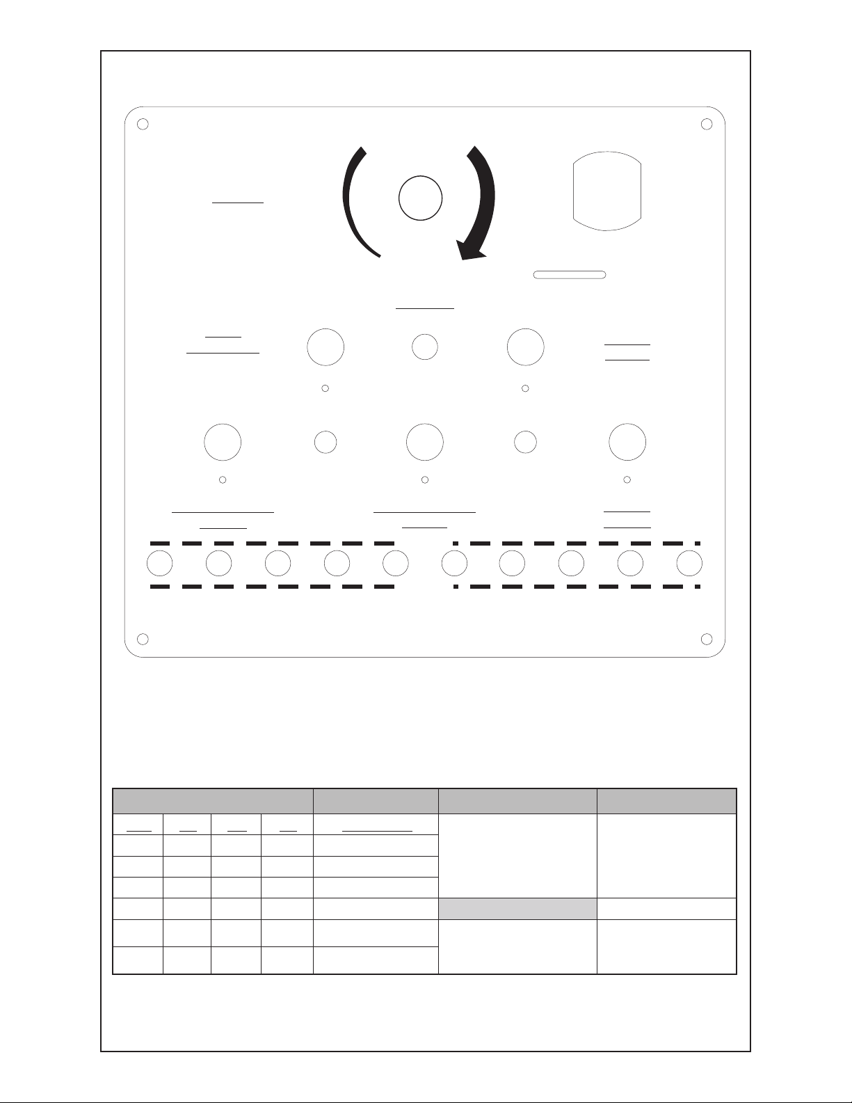
Section 2 SYSTEM CONTROLS AND FRONT PANEL
HEAT
(PULSE WIDTH)
MODE
HEAT
REMOTE
LOCAL
BKGND
LEVEL
PULSE
LEVEL
PULSE
WIDTH
BKGND
SLOPE
PULSE
SLOPE
PULSE
HEIGHT
INDUC-
TANCE
RISE
TIME
FREQ.
HEAT
INDUCTANCE
(NORMAL MIN:CCW)
PULSE HEIGHT
(NORMAL MAX:CW)
(4)
1 2 3 4
7
98 10
5
6
(1)(7)
(6)
(5)
PULSE
LEVEL
BACKGROUND
SLOPE
BACKGROUND
LEVEL
PULSE
SLOPE
WIRE
DIAMETER
(FREQUENCY)
(FREQ-WIDTH)
(9)
(2)
(10)
(3)
I
N
C
R
E
A
S
E
%nIeriW %nIeriW
%nIeriW
%nIeriW %nIeriW ssecorP ssecorP
ssecorP
ssecorP ssecorP leveldnuorgkcaB leveldnuorgkcaB
leveldnuorgkcaB
leveldnuorgkcaB leveldnuorgkcaB teSyrotcaF teSyrotcaF
teSyrotcaF
teSyrotcaF teSyrotcaF
.aiD LA SS TS leveLesluP
%32lairetaMnihT
%62lairetaM.gvA
%23lairetaMkcihT
%51ecnatcudnI
%001emiTesiR
%001thgieHesluP
020. 49 65 52 %06LA3404
%32lairetaMnihT
%62lairetaM.gvA
%23lairetaMkcihT
%51ecnatcudnI
%001emiTesiR
%001thgieHesluP
030. 57 83 22 %17LA6535
%32lairetaMnihT
%62lairetaM.gvA
%23lairetaMkcihT
%51ecnatcudnI
%001emiTesiR
%001thgieHesluP
530. 65 82 02 %57sselniatS
%32lairetaMnihT
%62lairetaM.gvA
%23lairetaMkcihT
%51ecnatcudnI
%001emiTesiR
%001thgieHesluP
540. 83 02 02 %48leetSdliM
epolS epolS
epolS
epolS epolS
250. 82 02 81
%02epolsdnuorgkcaB
%02epolsesluP
roflaunameeS
dnaatadlanoitidda
selpmaxe
260. 81 81 61
%02epolsdnuorgkcaB
%02epolsesluP
roflaunameeS
dnaatadlanoitidda
selpmaxe
Set Mode switch to "HEAT". Set Wire Diameter, Pulse Level (process) and background level per chart.
Control weld heat with "HEAT" control. Trim arc length with wire feeder rate control.
MK 2000A - Owner's Manual - Page 9
Page 10

Section 3 GENERAL
The MK2000A Electronic Pulsed Welding Power Supply is designed to
provide precision controlled, highly efcient welding power in a compact,
extremely reliable form.
The demands of modern fabrication techniques, with well- designed parts
accurately tted together, require exceptionally well controlled welding wire
feed and welding power control. The MK Cobramatic Wire Feed Systems,
long known for precision wire feeding for critical applications are now
matched with a precision power supply. The combination is exceptionally
well suited for xtured or robotic welding, although the exceptionally stable
characteristics also make hand welding much easier.
The welding engineer will appreciate the exibility to utilize constant voltage,
constant current, pulsed welding and unique combinations of all in a single
compact, efcient unit.
Section 4 DESIGN
Electrical
The MK2000A is a transistorized inverter power supply intended for use on
three phase 208 to 277 volt and 380 to 460 volt, 4 wire wye (with neutral),
50/60 Hertz supply circuits. (See page 24 for more details) The unit will also
operate on single phase 208 to 277 volt circuits, although the reduced power
factor may require limiting the duty cycle based on the volt ampere capacity
of the primary wiring.
The input power is converted to direct current and a switching inverter utilized
to generate alternating current at 20,000 hertz.
A compact, low-loss transformer steps the high voltage down to the welding
voltage range where it is rectied and ltered for output.
The inverter is controlled by a digital/analog control system which permits an
exceptional range of voltage, current and waveform controls.
For constant voltage (CV) operation, the output voltage is sensed and
compared with a digital reference. The inverter switch is controlled on a cycle
by cycle basis to hold the output at the reference value over the entire load
range. To provide spatter free welding conditions, slope may be added so
that the output voltage decreases with increasing current. Any slope from 0
volts per 100 amperes to vertical (constant current) may be set.
For constant current (CC) operation, the output current is sensed and
compared with a digital reference. The inverter switch is controlled on a
cycle by cycle basis to hold the output at the reference value over the entire
load range.
Pulsed operation is provided whereby the background voltage set by the
background level control is increased periodically. These pulses may
increase the output by any amount up to 100% of the power supply capacity.
Pulse rates may be any frequency from 20 pulses per second to 2000 pulses
per second. This, of course, includes the common pulse frequencies of 60
and 120 pulses per second available from thyristor supplies operated at line
frequency. Pulse widths may be any value from 0 to 100% of the pulse
period. In addition, the pulse shape may be controlled to provide a gradual
rise and fall (symmetrical), when an external control computer is used.
An exceptional capability is provided by the MK2000A through the use of
the Pulse Level and Pulse Slope controls in conjunction with the Background
Level and Background Slope. These two sets of controls function identically
cept that the pulse modulation is only added to the Background Control.
MK 2000A - Owner's Manual - Page 10
Page 11

The combination may be used to create a wide range of welding
characteristics. For example, when welding thick aluminum sections, CC
operation is often desired due to the increased penetration. In this instance
the Background Level is set to the desired operating voltage (e.g. 20 volts)
and the Background Slope set to a typical CV slope of 4 volts per 100
amperes (19% on dial); the welding condition will be standard CV. To limit
the current increase during the short circuit transfer interval, the Pulse Level
may be set to the desired maximum current (e.g. 240 amps) with a Pulse
Slope of 32 volts per 100 amps (66% on dial) or typically CC.
Another application of the Pulse Level Control is Pulsed Welding Operation.
Conventional pulsed supplies provide increased voltage during the pulse
interval, resulting in a current peak. Since the operating mode is that of
constant voltage, the actual current peak depends very critically on the load
impedance (wire feed rate and tip-to-work distance).
Using the Pulse Level Control with the Pulse Slope set for Constant Current
operation, the pulses on the pulse height may be set to 100%, permitting the
power supply to go to maximum output voltage. The pulse current is then
controlled by the Pulse Level, which is set to the desired peak current. Under
these conditions, the welding condition during the pulse is constant current,
and largely independent of wire feed rate and tip-to-work distance.
The MK2000A has built in protective circuitry to protect it from excessively
high or low input voltage and from any load condition. Under overload
conditions, the unit will automatically shut down and reset when conditions
are normal.
The physical layout logically separates input, switching, output and control
functions for ease of fault isolation and sub-assembly replacement. All
components are very conservatively rated and reliability is exceptional.
Mechanical
Careful attention has been given to the mechanical and thermal design of the
power supply. Recognizing the difcult environment in which such equipment
must operate, the MK2000A utilizes a heat exchanger design to eliminate
dust and dirt from the electronic components.
Although the circuit design is exceptionally efcient, it is necessary to remove
heat from the high current devices. This is accomplished by mounting the
input and output rectiers, switching transistors, main transformer and output
inductor on nned aluminum heat sinks which conduct the heat directly out
of the enclosure and into the air stream from a rear mounted cooling fan.
Outside air is not passed through the electronic enclosure.
All components are securely mounted to insure circuit integrity in spite of the
inevitable rough handling.
The compact size and light weight of this ten kilowatt power supply makes
handling much easier - never requiring hoists or fork lifts to position the unit.
Section 5 MK2000A CONTROL PANEL **
Background Level: Relates to the background level. This is background
voltage for a slope setting of ‘O‘ (CV) and background current for a slope
setting of 100 (CC).
Pulse Level: Also relates to the background level and slope. It is normally set
to establish a limiting value of current (slope near 100) when in short circuit
transfer mode or in pulse mode.
Pulse Width: This control may be set to make the actual pulse length 0% to
100% of the pulse interval.
MK 2000A - Owner's Manual - Page 11
Page 12

Background Slope: Adjustable from Constant Voltage to Constant Current.
Pulse Slope: Adjustable from Constant Voltage to Constant Current.
Pulse Height: This control determines the height of the output pulse. The
pulse is added on top of the background level so the total output during
the pulse is the sum of the Background Level setting plus the Pulse Height
setting.
Inductance: This control creates the electronic equivalent of output
inductance. This limits the rate of rise of current during short circuit transfer
without limiting the peak current. This control is factory set to 15%; however,
when -0- inductance is required, it may be disabled by placing the inductance
switch to remote.
Pulse Rise Time: This control determines the rise (and symmetrical fall) time
of the pulse. It may be used to change the rectangular pulse to a trapezoidal
or triangular shape. This control is adjustable through an external control
computer only.
Pulse Frequency: This control may be set to provide pulses at any repetition
rate from 20 pulses per second to 2000 pulses per second.
Heat: This control adjusts the pulse frequency while maintaining a preset
pulse width. The "ON TIME" (pulse width) is determined by the wire diameter
control.
Mode Selector: The mode selector switch allows the frequency and
pulse width to be controlled independently of each other or operate in the
“Heat” Mode.
** See Control Panel Detail (Section 2)
Section 6 OPERATING CHARACTERISTICS
The operating characteristics of the MK2000A cover a very wide spectrum,
however the operation may be easily understood by considering it in
relationship to conventional supplies.
Non-Pulsed Operation
Constant Voltage
Operation as a Constant Voltage (potential) power supply is shown in
Figure 1. This is the operation obtained when the Pulse Height control is set
to -0- and the Pulse Level is disabled by setting it to 100% with the Pulse
Slope set to -0-.
With the Background Slope control set to -0-, the Background Level control
MK 2000A - Owner's Manual - Page 12
Page 13

sets the power supply voltage output. This is shown as line ‘A’ as set to 24
volts. There is no slope and thus the voltage remains constant from below
50 amperes to over 300 amperes. The resulting harsh arc may be softened
by providing some slope as shown in lines ‘B’ & ‘C’. Setting the Background
slope to 15% results in a slope of just slightly more than 3 volts per 100
amperes - a commonly used value (line B). The slope may be increased
continuously until at 100% on the Background Slope control the line becomes
vertical and the power supply is operating as a very stiff Constant Current
(CC) source.
A notable feature of the MK2000A is that the slope control is referenced to the
diagonal ‘control line’ so that the operating voltage stays relatively constant
when the slope is changed. Therefore, there is no need to calculate open
circuit voltage regardless of the slope setting.
While welding, the output voltage and current follow the appropriate line
(A,B,C,etc.) up to the full 360 ampere capability of the supply.
Constant Current
Operation as a Constant Current power supply is shown in Figure 2. This
is the operation obtained when the Pulse Height control is set to -0- and the
Pulse Level disabled by setting it to 100% with the Pulse Slope set to -0-.
With the Background Slope control set to 100%, the Background Level control
sets the power supply current output. This is shown as line “A” as set to
170 amperes. There is no slope and the current remains constant from
short circuit conditions (zero volts) to the maximum capability of the power
supply at 50 volts. A more typical “drooper” curve is obtained by setting the
Background Slope control to less than 100% as shown in curves “B” and
“C”. Curve “C” at approximately 33 volts per 100 amperes is obtained with a
Background Slope setting of 66%.
The output characteristic curves just described for CV and CC welding may
be compared with “typical” curves representing the majority of presently
available CV and CC welding power sources, as obtained from supplier
catalogs, actual equipment measurements and the AWS Welding Handbook.
Typical curves are shown in Figure 3.
The Constant Current supplies usually start with a high open circuit voltage
and ‘droop’ steeply on the volt/ampere plot. As the output current setting is
decreased, the slope tends to become steeper. Supplies with lower open
circuit voltages (eg 60 volts) have substantially less slope, particularly at
higher currents.
The MK2000A may be set to closely match any of the slopes shown within
the limits of 50 volts and 360 amperes, since the slope is electronically
controlled and not just the result of a high open circuit voltage combined with
a high resistance circuit.
The conventional constant voltage supplies provide an open circuit voltage
MK 2000A - Owner's Manual - Page 13
Page 14

slightly higher than the desired welding voltage. A small amount of circuit
resistance is utilized to provide the desired slope. This is a power absorbing
element and reduces the efciency of the supply.
The MK2000A achieves its slope by an electronic control which does not add
loss to the circuit. It is thus substantially more efcient than the conventional
supply. The output voltage is set along the diagonal ‘control line’ and thus is
much more representative of the desired welding voltage. As may be seen,
changing the slope has a smaller effect on the output voltage at welding
current, although signicant changes in slope may require output voltage
readjustment.
With a CV power supply, it is often necessary to use more slope than
desired to avoid excessive current surges during arc initiation and short
circuit transfer. Some supplies are provided with a variable (or tapped)
inductor which limits the rate of change of current, however this makes the
supply both larger and more expensive. The MK2000A has an ‘electronic
inductor’ which provides the same output waveform, under short circuit
conditions, as would exist with an iron cored inductor. The inductor covers the
equivalent range of 0 to 3 millihenries.
A second method exists to provide for current limiting on short circuit - called
Dual Slope control. This is shown in Figure 4. The Background Slope
control is set for CV operation at 3 volts per 100 amperes (15%) and the
Background Level at the desired welding voltage - here shown as 18 volts
at pivot point ‘A’.
MK 2000A - Owner's Manual - Page 14
Page 15

The ‘Pulse Slope’ is set for CC operation at 38 volts/100 amperes (70%) and
the Pulse Level is set to 175 amperes at pivot point “B”.
Welding at these settings results in a CV operating mode with wire feed
rates adjusted to provide any current between about l00 and 200 amperes.
Short circuit current, however, is limited to 250 amperes by the Pulse Level
setting.
The Pulse Level and Slope may also be adjusted to any desired values, and
are independent of the Background Level and Slope. It is not necessary for
point “B” to be set above point “A”, although this will normally be the case.
The only difference in operation between the Background Level/Background
Slope and the Pulse Level/Pulse Slope is that pulse operation adds to the
Background Level and does not change the Pulse Level.
Inductance may be used with any combination of other settings.
Pulse Operation
The MK2000A provides a range of operating capabilities not available in any
general purpose welding power supply.
Pulse operation is used to provide a measure of independence in the control
of heat input, current density during material transfer, and arc voltage which
effects both heat and cleaning capability.
The majority of available pulsed welding power supplies operate with a
background voltage and then induce extended ring of one or two thyristors
to provide voltage pulses at 60 or 120 pulses per second. (360 pps with three
phase operation) The current resulting from these voltages depends on the
ring point which, in turn, controls the pulse duration (width). It is usually
described in terms of the peak current value.
MK2000A Parameter Set-Up
In pulsed spray welding the current is varied from the background level to a
peak level. The background level is well below the transition current while
the peak level is well into the spray arc region, Figure 5. During the peak
level one droplet is transferred to the work. The current then drops to the
background level which allows the puddle to cool, at which time no metal
is transferred.
MK 2000A - Owner's Manual - Page 15
Page 16

Wire Diameter
To obtain the smooth one drop transfer during the peak level the “On” time
(pulse width) must be varied, depending on the wire diameter. For example,
.030 requires 1/2 of a millisecond and .045 requires 1-1/2 milliseconds. The
WIRE DIAMETER Control on the MK 2000A therefore sets the "ON TIME"
(pulse width).
Pulse Level
Because different alloys melt at different temperatures, the height of the pulse
must also be varied. The PULSE LEVEL therefore limits the height of the
pulse depending on the alloy. For example, the Pulse Level for 4043 is set
to 60 (60% of 300 Amps = 180 Amps) whereas 5356 with its higher melting
temperature is set to 71 (71% of 300 Amps = 213 Amps Max.).
Heat
When changing plate size or for ne tuning, the “HEAT” Control may be
adjusted. With the "ON TIME" (pulse width) preset by the Wire Diameter
control the Heat control moves the pulses closer together (more heat) or
further apart (less heat) without changing the pulse width. Figure 6. Keep in
mind that when you increase your heat you must also increase wire speed.
Note: When operating in the Frequency Width mode the frequency and pulse
width are set independently of each other. Increasing the frequency in this
mode decreases the "ON TIME" (pulse width) proportionately.
MK 2000A - Owner's Manual - Page 16
Page 17

Background Level
When the pulse drops to the background level, it must be at a point high
enough to maintain an arc yet low enough to cool the puddle. Normally the
thickness of the material will determine the Background Level.
Slope
The MK 2000A is capable of operating in either constant voltage (CV) or
constant current (CC). Because of the problems associated with CC Mig
welding, CV operation is most common. A power supply with no slope would
produce a very harsh arc with excessive spatter. Adding slope reduces the
voltage for the same amount of amperage, thereby softening the arc. Setting
the MK2000A’s slope controls to 20% will provide a common slope of 4V/100
Amps.
Inductance
Inductance added to the MK2000A tends to round off the falling pulse. This
increases the “arc on” time which makes the puddle more uid. Because
aluminum solidies so quickly, it is recommended to add 15% (7 turns)
inductance when welding aluminum whereas steel and stainless steel require
little or no inductance. The MK2000A is factory set at 15% inductance. When
-0- inductance is needed place the inductance switch on remote.
Pulse Height
By leaving the Pulse Height Control at 100%, we can limit the height of the
pulse with the Pulse Level Control.
Figure 7 shows the output voltage into a constant load. The pulse period
is the reciprocal of the pulse frequency (16.6 milliseconds at 60 pulses per
second).
MK 2000A - Owner's Manual - Page 17
Page 18

The effect that Rise Time has on the pulse is shown in (Figure 8). At 100%
the pulse is rectangular, but by turning the rise time toward 0%, the leading
and trailing edges become increasingly tapered. Slow rise times and narrow
pulses will result in the output voltage never reaching the maximum voltage.
In this operating mode, the welding engineer has almost complete control of
the welding conditions throughout the entire heat and metal transfer portions
of the weld
Control Characteristics
All controls are calibrated to provide -0- to 100% of the controlled parameter
maximum value. Thus the Background Slope control provides a slope of -0volts per ampere when set to CV (0%) and -0- amperes per volt when set
to CC (100%).
With 0% slope (CV) the Background Level control provides 0-50 V output.
For example 18 volts is 36% of 50 volts, or 36.0 on the dial.
With 100% slope (CC) the Background Level control provides 0-300 amperes
output. For example 180 amperes is 60% of 300 amperes or 60.0 on the
dial.
A control line may be drawn on a graph of voltage vs. current which connects
the origin (-0- volts, -0- amperes) with the maximum (50 V., 300 A.). The
operating volt-ampere line will always cross this control line at the value
corresponding to the dial setting. For example, an output dial setting of 60%
will provide a volt-ampere line passing through 30 volts (.60 X 50V) and
180 amperes (.60 X 300A). As shown in Figure 1 and Figure 2, changing
the background slope rotates this volt-ampere line around the set point and
controls the no load and short circuit values of voltage and current.
The Pulse Level and Pulse Slope controls operate in an identical manner
(except that the pulse operation adds to the Background Level control setting
only). Both Background and Pulse controls may be used simultaneously to
create an operating volt-ampere line such as shown in Figure 4.
The Inductance Control shapes the output current to approximately match
that of an inductor of -0- to 3 millihenries. This is most useful in welding steel
or similar metals to control the rate of use of arc current.
The Pulse Controls include Repetition Rate (frequency), Height, Width, and
Rise Time. The Repetition Rate may be varied from 20 to 2000 pulses per
second (pps), thus 60 pps is 3% of 2000 and 120 pps is 6% of 2000 (or 6
on the dial). The pulse Height adds to the Background level control so that,
in the CV mode, the pulse height may be -0- to 50 volts. For example, if the
Background Level is at 30% (15V) and the Pulse Height is set to 40% (20V)
the “background” will be 15 volts and the pulses will be 35 volts (15 + 20).
The discussion of current limit on the output applies equally to the output
plus pulse levels.
With the Background Slope set to CC conditions (nearer 100% slope) the
pulse height still adds to the background level and represents a current
controlled pulse rather than a voltage controlled pulse. As indicated
previously, the Pulse Level and Slope may be used to provide a constant
current condition during the pulse with a constant voltage background.
The Pulse Width control provides pulse widths from nearly 0% to 100% of
the pulse interval. Of course at -0- width there is no pulse and at 100%
there is no background level. Within rather wide limits, the heat in the weld
may be controlled by adjusting the pulse width with minimum effect on other
parameters.
The Pulse Rise Time may be used to limit the rate of voltage or current
rise during the pulse. The leading and trailing edges of the pulse are
MK 2000A - Owner's Manual - Page 18
Page 19

symmetrically controlled. Excessive rise time may result in the pulse never
reaching the set value. With the width set at a high percentage, excessive
rise time will prevent the output from dropping back to the “background” value.
All functions may be remotely controlled by application of a -0- to 10 V. Direct
Current level to the appropriate pins of the remote connector and placing the
control switch in the “Remote” position. (See Page 20)
Control Summary - 0% to 100% dial settings (Calibration is in percent of
maximum value given).
Background Level 0 to 50 volts, 0-300 amperes
Background Slope 0 volts per ampere (CV) to 0 amperes per volt (CC)
Pulse Level 0 to 50 volts, 0-300 amperes
Pulse Slope 0 volts per ampere (CV) to 0 amperes per volt (CC)
Inductance 0 to 3 millihenries equivalent
Pulse Rate 20 to 2000 pulses per second
Pulse Height 0 to 50 volts, 0 to 300 amperes
Pulse Width 0 to l/pulse frequency
Pulse Time 200 msec to no rise
(see graph)
The following Figures show control characteristics:
Figure 9 Background Slopw & Pulse Slope
Figure 10 Background Level & Pulse Level
Figure 11 Output Wave Form - 50% Pulse Width vs Frequency
Figure 12 Pulse Rise Time vs Dial Settings
The MK2000A and the C1-A Remote Control
The 25 pin D connector on the front panel of the MK2000A enables the power
supply to be remotely controlled through 0 to 10V analog commands. To use
an existing C1-A Pendant, P/N 001-0002, with the MK2000A, the following
25 pin "D" connector cable assembly must be used: P/N 843-0306. When
the C1-A pendant is used in conjunction with the MK2000A, several operating
modes are avialable.
Remote Heat Only
Set desired parameter on power supply, insuring that the mode selector
switch is in the “heat” position. Placing switch 10 in the remote position now
removes the heat control from the front panel to the C1-A pendant.
Full Pendant Operation
Placing switches 1 - 10 in remote provides full C1-A type operation.
NOTE:
Because the C1-A is calibrated to the MK2000’s 40 volt range rather than the
MK2000A’s 50 volt range, it may be necessary to recalibrate the C1-A Pendant.
When recalibration is necessary, consult the factory for procedure instructions.
MK 2000A - Owner's Manual - Page 19
Page 20

REMOTE CONNECTOR PIN ASSIGNMENTS
PIN FUNCTION
1 Pulse Width / Heat
2 Pulse Frequency
3 Pulse Level
4 Rise Time
5 Pulse Height
6 Pulse Slope
7 Background Slope
8 Background Level
9 Contactor - Closing Contacts
10 Spare
11 Arc Establish *
12 Inductance
13 Spare
14 Ground
15 + 10V (Source) (Contactor)
16 Spare
17 Amps Ref.
18 Volts Ref.
19 Spare
20 Spare
21 Spare
22 Spare
23 Spare
24 + 12V Aux. Output
25 Aux. Common Output
NOTE:
Contactor may be closed through 25 pin “D” connector
with “closing contact only” (no 115 VAC) on pins 9 & 15.
* ARC EST. (PIN 11) is a logic type signal that goes from open to +10 VDC when the power
supply is deliver 30 Amps or more. The load on this pin must not exceed more than 10 MA. (1000
OHMS minimum) referenced to Pin 14.
MK 2000A - Owner's Manual - Page 20
Page 21

Volts per
1
00 Amps
Slope Dial Setting
Operating
Lev
el
(P
ivot
Point)
Voltage
(V
olts)
Level Dial Setting
Operating
Lev
el (Pivot Point)
Current
(Am
peres
)
Fig. 9
Fig. 10
MK 2000A - Owner's Manual - Page 21
Page 22

Fig. 11
Volts
Time in Milliseconds
Rise
Time in Microseconds
Rise Time Dial In Percent
Fig. 12
MK 2000A - Owner's Manual - Page 22
Page 23

noisrevnoCA0002KMot0002KM
foepolSAroF foepolSAroF
foepolSAroF
foepolSAroF foepolSAroF
A001/V A001/V
A001/V
A001/V A001/V
oTlaiDepolSteS oTlaiDepolSteS
oTlaiDepolSteS
oTlaiDepolSteS oTlaiDepolSteS
otlevelteS otlevelteS
otlevelteS
otlevelteS otlevelteS
yb.tlum0002KM yb.tlum0002KM
yb.tlum0002KM
yb.tlum0002KM yb.tlum0002KM
tuptuOteS tuptuOteS
tuptuOteS
tuptuOteS tuptuOteS
%otepolS %otepolS
%otepolS
%otepolS %otepolS
gniviGnwohS gniviGnwohS
gniviGnwohS
gniviGnwohS gniviGnwohS
stloVderiseD stloVderiseD
stloVderiseD
stloVderiseD stloVderiseD
001rep 001rep
001rep
001rep 001rep
serepmA serepmA
serepmA
serepmA serepmA
0002 A0002
% % 08.
A0002KMteS
otleveLtuptuO
leveL0002KM
ehtybdeilpitlum
enilnorebmun
.desuepolShtiw
timiLroftaepeR
.leveLdnaepolS
2 31 11 28.
A0002KMteS
otleveLtuptuO
leveL0002KM
ehtybdeilpitlum
enilnorebmun
.desuepolShtiw
timiLroftaepeR
.leveLdnaepolS
4 32 91 48.
A0002KMteS
otleveLtuptuO
leveL0002KM
ehtybdeilpitlum
enilnorebmun
.desuepolShtiw
timiLroftaepeR
.leveLdnaepolS
6 13 621 58.
A0002KMteS
otleveLtuptuO
leveL0002KM
ehtybdeilpitlum
enilnorebmun
.desuepolShtiw
timiLroftaepeR
.leveLdnaepolS
8 83 23 68.
A0002KMteS
otleveLtuptuO
leveL0002KM
ehtybdeilpitlum
enilnorebmun
.desuepolShtiw
timiLroftaepeR
.leveLdnaepolS
01 34 83 88.
A0002KMteS
otleveLtuptuO
leveL0002KM
ehtybdeilpitlum
enilnorebmun
.desuepolShtiw
timiLroftaepeR
.leveLdnaepolS
21 74 24 88.
A0002KMteS
otleveLtuptuO
leveL0002KM
ehtybdeilpitlum
enilnorebmun
.desuepolShtiw
timiLroftaepeR
.leveLdnaepolS
41 15 64 98.
A0002KMteS
otleveLtuptuO
leveL0002KM
ehtybdeilpitlum
enilnorebmun
.desuepolShtiw
timiLroftaepeR
.leveLdnaepolS
61 55 94 09.
A0002KMteS
otleveLtuptuO
leveL0002KM
ehtybdeilpitlum
enilnorebmun
.desuepolShtiw
timiLroftaepeR
.leveLdnaepolS
81 75 25 09.
A0002KMteS
otleveLtuptuO
leveL0002KM
ehtybdeilpitlum
enilnorebmun
.desuepolShtiw
timiLroftaepeR
.leveLdnaepolS
02 06 55 19.
A0002KMteS
otleveLtuptuO
leveL0002KM
ehtybdeilpitlum
enilnorebmun
.desuepolShtiw
timiLroftaepeR
.leveLdnaepolS
MK 2000A - Owner's Manual - Page 23
Page 24

FREQUENCY CALCULATION PROCEDURES
Given: Wire Diameter Dial Setting ...................................38%
Heat Setting .........................................................30%
Convert "Wire Diameter" to pulse width using chart. For example, 38%
equals 1.47 milliseconds.
Formula= HEAT DIAL X 10 = 30 X 10 = 300 = 204 PPS
PULSE WIDTH (ms) 1.47 1.47
WIRE PULSE WIDTH
DIAMETER IN
DIAL SETTING M.SEC
.02 ...........................................25.25
.04 ...........................................12.74
.06 ............................................8.57
.08 ............................................6.48
.10 ............................................5.23
.12 ............................................4.39
.14 ............................................3.79
.16 ............................................3.34
.18 ............................................2.98
.20 ............................................2.70
.22 ............................................2.47
.24 ............................................2.27
.26 ............................................2.11
.28 ............................................1.97
.30 ............................................1.84
.32 ............................................1.73
.34 ............................................1.64
.36 ............................................1.55
.38 ............................................1.47
.40 ............................................1.40
.42 ............................................1.34
.44 ............................................1.28
.46 ............................................1.22
.48 ............................................1.17
.50 ............................................1.13
.52 ............................................1.08
.54 ............................................1.04
.56 ............................................1.00
.58 ............................................0.97
.60 ............................................0.93
.62 ............................................0.90
.64 ............................................0.87
.66 ............................................0.84
.68 ............................................0.82
.70 ............................................0.79
.72 ............................................0.76
.74 ............................................0.74
.76 ............................................0.72
.78 ............................................0.70
.80 ............................................0.68
.82 ............................................0.65
.84 ............................................0.64
.86 ............................................0.62
.88 ............................................0.60
.90 ............................................0.58
.92 ............................................0.56
.94 ............................................0.55
.96 ............................................0.53
.98 ............................................0.52
1.00 ...........................................0.50
MK 2000A - Owner's Manual - Page 24
Page 25

Section 7 INPUT POWER CONNECTIONS
Regardless of what type of input power that you use for the MK2000A,
you must provide a protected line (fused) disconnect in accordance with
all applicable electrical codes. The MK2000A is equipped with an internal
primary switch, but no fuses are provided. Line fuses should be 60 ampere
maximum (Buss non-60 recommended). Connection cables must be sized to
conform to national and local electrical code requirements.
WARNING:
THE 2000A COMES SETUP FOR 208-230VAC SINGLE OR THREE PHASE
(SEE BELOW). FOR HOOKUP OF 480VAC 4 WIRE WYE PLUS GROUND YOU
WILL NEED A SPECIAL PLATE. CONTACT MK PRODUCTS TECHNICAL
SERVICE FOR INSTRUCTION.
1 PHASE 208-230 VAC
When connecting Single (1) Phase
208-230VAC, you will use only the X, Y and
Ground terminals, DO NOT use the Z or
NEUTRAL terminal with this input power.
208-230 VAC ONLY
SINGLE OR 3 PHASE
Rear connection panel on MK2000A
X Y Z NEUTRAL
3 PHASE 208-230 VAC
When connecting 3 Phase 208-230VAC, you
will use the X, Y ,Z and Ground terminals,
DO NOT use the NEUTRAL terminal with
this input power.
208-230 VAC ONLY
SINGLE OR 3 PHASE
Rear connection panel on MK2000A
X Y Z NEUTRAL
CUSTOMER PROVIDED FUSED
DISCONNECT
NON-SHARED
MK 2000A - Owner's Manual - Page 25
GROUND
#12 green
wire
GROUND
#12 green
wire
CUSTOMER PROVIDED FUSED
DISCONNECT
NON-SHARED
Page 26

MK 2000A - Owner's Manual - Page 26
Page 27

MK 2000A - Owner's Manual - Page 27
Page 28

Effective March 1, 2001
This warranty supersedes all previous MK Products warranties and is
exclusive, with no other guarantees or warranties expressed or implied.
LIMITED WARRANTY - MK Products,Inc.,Irvine,California
warrants that all new and unused equipment furnished by MK
Products is free from defect in workmanship and material as
of the time and place of delivery by MK Products. No warranty
is made by MK Products with respect to trade accessories or
other items manufactured by others. Such trade accessories
and other items are sold subject to the warranties of their
respective manufacturers, if any.
MK Products’ warranty does not apply to components having
normal useful life of less than one (1) year, such as relay
points, wire conduit, tungsten, and welding torch parts that
come in contact with the welding wire, including nozzles, nozzle
insulators, and contact tips where failure does not result from
defect in workmanship or material.
In the case of MK Products’ breach of warranty or any other
duty with respect to the quality of any goods, the exclusive
remedies therefore shall be at MK Products’ option: (1) repair;
(2) replacement; (3) where authorized in writing by MK Products,
the reasonable cost of repair or replacement at our Irvine,
California plant; or (4) payment of or credit for the purchase
price (less reasonable depreciation based upon actual use)
upon return of the goods at customer’s risk and expense.
Upon receipt of notice of apparent defect or failure, MK
Products shall instruct the claimant on the warranty claim
procedures to be followed.
As a matter of general policy only, MK Products may honor
an original user’s warranty claims on warranted equipment
in the event of failure resulting from a defect within the
following periods from the date of delivery of equipment to
the original user:
1. Torches, Weldheads, and Water Recirculators........... 1 year
2. All Other Equipment ................................................. 3 years
3. Repairs ....................................................................90 days
Classication of any item into the foregoing categories shall be
at the sole discretion of MK Products. Notication of any failure
must be made in writing within 30 days of such failure.
A copy of the invoice showing the date of sale must accompany
products returned for warranty repair or replacement.
All equipment returned to MK Products for service must be
properly packaged to guard against damage from shipping.
MK Products will not be responsible for any damages resulting
from shipping.
Normal surface transportation charges (both ways) for products
returned for warranty repair or replacement will be borne by MK
Products, except for products sold to foreign markets.
ANY EXPRESS WARRANTY NOT PROVIDED HEREIN AND
ANY IMPLIED WARRANTY, GUARANTY, OR REPRESENTATION AS TO PERFORMANCE, AND ANY REMEDY FOR
BREACH OF CONTRACT WHICH, BUT FOR THIS PROVISION,
MIGHT ARISE BY IMPLICATION, OPERATION OF LAW,
CUSTOM OF TRADE, OR COURSE OF DEALING, INCLUDING
ANY IMPLIED WARRANTY OF MERCHANTABILITY OR OF
FITNESS FOR PARTICULAR PURPOSE, WITH RESPECT TO
ANY AND ALL EQUIPMENT FURNISHED BY MK PRODUCTS,
IS EXCLUDED AND DISCLAIMED BY MK PRODUCTS.
EXCEPT AS EXPRESSLY PROVIDED BY MK PRODUCTS
IN WR IT IN G, MK P RODU CT S A RE INTEN DE D F OR
ULTIMATE PURCHASE BY COMMERCIAL/INDUSTRIAL
USERS AND FOR OPERATION BY PERSONS TRAINED
AND EXPERIENCED IN THE USE AND MAINTENANCE OF
WELDING EQUIPMENT AND NOT FOR CONSUMERS OR
CONSUMER USE. MK PRODUCTS WARRANTIES DO
NOT EXTEND TO, AND NO RE-SELLER IS AUTHORIZED
TO EXTEND MK PRODUCTS’ WARRA NTIES TO AN Y
CONSUMER.
MK Products, Inc.
16882 Armstrong Ave.
Irvine, CA 92606
Tel (949)863-1234
Fax (949)474-1428
DATE : March 1, 2001
Page 29

MK Products, Inc.
16882 Armstrong Avenue
Irvine, California 92606
Tel 949/863-1234
Fax 949/474-1428
 Loading...