

MK Products CobraTig 150 SM 254-153, CobraTig 150 SM 254-252, CobraTig 150 SM Owner's Manual

CobraTig® 150 SM
Owner’s Manual
Product: CobraTig
Manual: 091-0675
Serial: 13110001
Voltage Rating: 100/120/208-
220/230-240VAC
Revision: Nov 2013 Rev B
Model Number: 254-153
254-252
®

Table of Contents
INTRODUCTION .......................................................................1
Section 1 Technical Information ...........................................2
Section 2 Mechanical Information ........................................2
Section 3 Weldhead and Torches .........................................2
Section 4 Connections ........................................................3
Section 5 Operation ............................................................5
Section 6 Main Menu .........................................................6
Section 7 Weld Manual ......................................................6
Section 8 Weld Orbital ........................................................8
Section 9 Recall Program ....................................................9
Section 10 Save Program ....................................................10
Section 11 Auto Program Generator .....................................11
Section 12 Print Menu .......................................................12
Section 13 Calibration Menu ................................................14
Section 14 Communication Menu .........................................16
Section 15 Setup Menu .......................................................17
Section 17 Diagnostic Menu ...............................................18

European Community (CE) Products
Note
Declaration of Conformity for
This information is provided for units with CE certication (see rating label on unit).
Manufacturer’s Name:
16882 Armstrong Ave.
Irvine, CA 92606
Declares that the product: CobraTig
conforms to the following Directives and Standards:
Electromagnetic Compatibility (EMC) Directive: 2004/108/EC
Electromagnetic Compatibility, (EMC): EN 60974-10: 2007
MK Products, Inc.
®
150 SM
Directives
Low Voltage Directive: 2006/95/EC
Standards
Torches And Guns For Arc Welding, EN 60974-7: 2005

SAFETY CONSIDERATIONS
ELECTRIC ARC WELDING EQUIPMENT
CAUTION : READ BEFORE ATTEMPTING INSTALLATION, OPERATION
OR MAINTENANCE OF THIS EQUIPMENT
1-1 INTRODUCTION
This equipment is intended for ultimate
application by commercial/industrial users
and for operation by persons trained and
experienced in the use and maintenance
of welding equipment. Operation should
not be undertaken without adequate training in the use of such equipment. Training
is available from many public and private
schools or similar facilities.
Safe practices in the installation, operation and maintenance of this equipment
requires proper training in the art, a careful study of the information provided with
the equipment, and the use of common
sense. Rules for safe use are generally
provided by suppliers of welding power
sources, compressed gas suppliers, and
electrode suppliers. Careful compliance
with these rules will promote safe use of
this equipment.
The following Safety Rules cover some
of the more generally found situations.
READ THEM CAREFULLY. In case of
any doubt, obtain qualied help before
proceeding.
1-2 GENERAL PRECAUTIONS
A. Burn Prevention
ELECTRIC ARC WELDING PRODUCES
HIGH INTENSITY HEA T AND UL TRAVIOLET RADIANT ENERGY WHICH MAY
CAUSE SERIOUS AND PERMANENT
EYE DAMAGE AND WHICH MAY DAMAGE ANY EXPOSED SKIN AREAS.
Wear helmet with safety goggles or
glasses with side shields underneath,
appropriate lter lenses or plates (protected by clear cover glass). This is a
must for welding or cutting (and chipping)
to protect the eyes from radiant energy
and ying metal. Replace cover glass
when broken, pitted, or spattered.
Medical first aid and eye treatment.
First aid facilities and a qualied rst aid
person should be available for each shift
unless medical facilities are close by for
immediate treatment of ash burns of the
eyes and skin burns.
Wear protective clothing - leather (or
asbestos) gauntlet gloves, hat, and high
safety-toe shoes. Button shirt collar and
pocket aps, and wear cufess trousers
to avoid entry of sparks and slag.
Avoid oily or greasy clothing. A spark
may ignite them.
Flammable hair preparations should not
be used by persons intending to weld
or cut.
Hot metal such as electrode stubs and
work pieces should never be handled
without gloves.
Ear plugs should be worn when working
on overhead or in a conned space. A
hard hat should be worn when others work
overhead.
B. Toxic Fume Prevention
WARNING: The use of this product may result in exposure to chemicals known to the
State of California to cause cancer and birth
defects or other reproductive harm.
Adequate ventilation. Severe discomfort, illness or death can result from fumes, vapors,
heat, or oxygen enrichment or depletion that
welding (or cutting) may produce. Prevent
them with adequate ventilation. NEVER
ventilate with oxygen.
Lead-, cadmium-, zinc-, mercury-, berylliumbearing and similar materials, when welded
or cut, may produce harmful concentrations
of toxic fumes. Adequate local exhaust ventilation must be used, or each person in the
area, as well as the operator, must wear an
air-supplied respirator. For beryllium, both
must be used.
Metals coated with or containing materials
that emit toxic fumes should not be heated
unless coating is removed form the work
surface, the area is well ventilated, or the
operator wears an air-supplied respirator.
Work in a conned space only while it is
being ventilated and, if necessary, while
wearing an air-supplied respirator.
Gas leaks in a conned space should be
avoided. Leaked gas in large quantities can
change oxygen concentration dangerously.
Do not bring gas cylinders into a conned
space.
Leaving conned space, shut OFF gas sup-
ply at source to prevent possible accumulation of gases in the space if downstream
valves have been accidentally opened or
left open. Check to be sure that the space
is safe before reentering it.
Vapors from chlorinated solvents can be de-
composed by the heat of the arc (or ame)
to form PHOSGENE, a highly toxic gas,
and other lung and eye irritating products.
The ultraviolet (radiant) energy of the arc
can also decompose trichloroethylene and
perchloroethylene vapors to form phosgene.
DO NOT WELD or cut where solvent vapors
can be drawn into the welding or cutting
atmosphere or where the radiant energy
can penetrate to atmospheres containing
even minute amounts of trichloroethylene
or perchloroethylene.
C. Fire and Explosion Prevention
Causes of re and explosion are: combus-
tibles reached by the arc, ame, ying
sparks, hot slag, or heated material, misuse of compressed gases and cylinders,
and short circuits.
BE AWARE THAT ying sparks or falling slag can pass through cracks, along
pipes, through windows or doors, and
through wall or oor openings, out of
sight of the goggled operator. Sparks
can y many feet.
To prevent res and explosion:
Keep equipment clean and operable, free
of oil, grease, and (in electrical parts) of
metallic particles that can cause short
circuits.
If combustibles are in area, do NOT weld
or cut. Move the work if practicable, to
an area free of combustibles. Avoid paint
spray rooms, dip tanks, storage areas,
ventilators. If the work cannot be moved,
move combustibles at least 35 feet away,
out of reach of sparks and heat; or protect
against ignition with suitable and snug-t-
ting, re-resistant covers or shields.
Walls touching combustibles on opposite
sides should not be welded on (or cut).
Walls, ceilings, and floor near work
should be protected by heat-resistant
covers or shields.
Fire watcher must be standing by with
suitable fire extinguishing equipment
during and for some time after welding
or cutting if:
1. Appreciable combustibles (including building construction) are within
35 feet.
2. Appreciable combustibles are further than 35 feet, but can be ignited by
sparks.
3. Openings (concealed or visible) in
oors or walls within 35 feet may expose
combustibles to sparks.
4. Combustibles adjacent to walls, ceilings, roofs, or metal partitions can be
ignited by radiant or conducted heat.
Hot work permit should be obtained
before operation to ensure supervisor’s
approval that adequate precautions have
been taken.
After work is done, check that area is free
of sparks, glowing embers, and ames.
An empty container that held combus-
tibles, or that can produce ammable or
toxic vapors when heated, must never
be welded on or cut, unless container
has rst been cleaned in accordance with
industry standards.
This includes: a thorough steam or
caustic cleaning (or a solvent of water
CobraTig® 150 Owner's Manual - Page i

washing, depending on the combustible’s
solubility), followed by purging and inerting with nitrogen or carbon dioxide, and
using protective equipment.
Water-lling just below working level may
substitute for inerting.
A container with unknown contents
should be cleaned (see paragraph
above). Do NOT depend on sense of
smell or sight to determine if it is safe to
weld or cut.
Hollow castings or containers must be
vented before welding or cutting. They
can explode.
Explosive atmospheres. NEVER weld
or cut where the air may contain ammable dust, gas, or liquid vapors (such
as gasoline).
D. Compressed Gas Equipment
The safe handling of compressed gas
equipment is detailed in numerous
industry publications. The following
general rules cover many of the most
common situations.
1. Pressure Regulators
Regulator relief valve is designed to protect only the regulator from overpressure;
it is not intended to protect any downstream equipment. Provide such protection with one or more relief devices.
Never connect a regulator to a cylinder
containing gas other than that for which
the regulator was designed.
Remove faulty regulator from service im-
mediately for repair (rst close cylinder
valve). The following symptoms indicate
a faulty regulator:
Leaks - if gas leaks externally.
Excessive Creep - if delivery pressure
continues to rise with downstream valve
closed.
Faulty Gauge - if gauge pointer does
not move off stop pin when pressurized,
nor returns to stop pin after pressure
release.
Repair. Do NOT attempt repair. Send
faulty regulators for repair to manufacturer’s designated repair center, where
special techniques and tools are used by
trained personnel.
2. Cylinders
Cylinders must be handled carefully to
prevent leaks and damage to their walls,
valves, or safety devices:
Avoid electrical circuit contact with cylinders including third rails, electrical wires,
or welding circuits. They can produced
short circuit arcs that may lead to a serious accident. (See 1-3C)
ICC or DOT marking must be on each cylinder. It is an assurance of safety when
the cylinder is properly handled.
Identifying gas content. Use only cylinders with name of gas marked on them;
do not rely on color to identify gas content. Notify supplier if unmarked. NEVER
DEFACE or alter name, number , or other
markings on a cylinder. It is illegal and
hazardous.
Empties: Keep valves closed, replace caps
securely; mark MT; keep them separate
from FULLS, and return promptly.
Prohibited use. Never use a cylinder or its
contents for other than its intended use,
NEVER as a support or roller.
Locate or secure cylinders so they cannot
be knocked over.
Passageways and work areas. Keep cylinders clear of areas where they may be
stuck.
Transporting cylinders. With a crane, use
a secure support such as a platform or
cradle. Do NOT lift cylinders off the ground
by their valves or caps, or by chains, slings,
or magnets.
Do NOT expose cylinders to excessive heat,
sparks, slag, and ame, etc. that may cause
rupture. Do not allow contents to exceed 55
degrees C (130 degrees F .) Cool with water
spray where such exposure exists.
Protect cylinders, particularly valves from
bumps, falls, falling objects, and weather.
Replace caps securely when moving cylinders.
Stuck valve. Do NOT use a hammer or
wrench to open a cylinder valve that cannot
be opened by hand. Notify your supplier.
Mixing gases. NEVER try to mix any gases
in a cylinder.
NEVER rell any cylinder.
Cylinder ttings should never be modied
or exchanged.
3. Hose
Prohibited use. Never use hose other
than that designed for the specied gas. A
general hose identication rule is: red for
fuel gas, green for oxygen, and black for
inert gases.
Use ferrules or clamps designed for the
hose (not ordinary wire or other substitute)
as a binding to connect hoses to ttings.
No copper tubing splices. Use only stan-
dard brass ttings to splice hose.
Avoid long runs to prevent kinks and abuse.
Suspend hose off ground to keep it from
being run over, stepped on, or otherwise
damaged.
Coil excess hose to prevent kinks and
tangles.
Protect hose from damage by sharp edges,
and by sparks, slag, and open ame.
Examine hose regularly for leaks, wear,
and loose connections. Immerse pressured
hose in water; bubbles indicate leaks
Repair leaky or worn hose by cutting area
out and splicing. Do NOT use tape.
4. Proper Connections
Clean cylinder valve outlet of impurities that
may clog orices and damage seats before
connecting regulator. Except for hydrogen,
crack valve momentarily, pointing outlet
away from people and sources of ignition.
Wipe with a clean, lintless cloth.
Match regulator to cylinder. Before connecting, check that the regulator label and
cylinder marking agree, and that the
regulator inlet and cylinder outlet match.
NEVER Connect a regulator designed
for a particular gas or gases to a cylinder
containing any other gas.
Tighten connections. When assembling
threaded connections, clean and smooth
seats where necessary. Tighten. If connection leaks, disassemble, clean, and
retighten, using properly tting wrench.
Adapters. Use a CGA adapter (available
from your supplier) between cylinder and
regulator, if one is required. Use two
wrenches to tighten adapter marked
RIGHT and LEFT HAND threads.
Regulator outlet (or hose) connections
may be identied by right hand threads
for oxygen and left hand threads (with
grooved hex on nut or shank) for fuel
gas.
5. Pressurizing Steps:
Drain regulator of residual gas through
suitable vent before opening cylinder
(or manifold valve) by turning adjusting
screw in (clockwise). Draining prevents excessive compression heat at
high pressure seat by allowing seat to
open on pressurization. Leave adjusting
screw engaged slightly on single-stage
regulators.
Stand to side of regulator while opening
cylinder valve.
Open cylinder valve slowly so that regulator pressure increases slowly. When
gauge is pressurized (gauge reaches
regulator maximum) leave cylinder
valve in following position: for oxygen
and inert gases, open fully to seal stem
against possible leak; for fuel gas, open
to less than one turn to permit quick
emergency shut-off.
Use pressure charts (available from
your supplier) for safe and efficient
recommended pressure settings on
regulators.
Check for leaks on rst pressurization
and regularly thereafter. Brush with soap
solution. Bubbles indicate leaks. Clean
off soapy water after test; dried soap is
combustible.
E. User Responsibilities
Follow all Safety Rules.
Remove leaky or defective equipment
from service immediately for repair.
Read and follow user manual instructions.
F. Leaving Equipment Unattended
Close gas supply at source and drain
gas.
G. Rope Staging-Support
Rope staging-support should not be
used for welding or cutting operation;
rope may burn.
1-3 ARC WELDING
Comply with precautions in 1-1, 1-2,
and this section. Arc Welding, properly
done, is a safe process, but a careless
CobraTig® 150 Owner's Manual - Page ii

operator invites trouble. The equipment
carries high currents at signicant voltages. The arc is very bright and hot.
Sparks y, fumes rise, ultraviolet and
infrared energy radiates, weldments are
hot, and compressed gases may be used.
The wise operator avoids unnecessary
risks and protects himself and others
from accidents.
A. Burn Protection
Comply with precautions in 1-2.
The welding arc is intense and visibly
bright. Its radiation can damage eyes,
penetrate lightweight clothing, reflect
from light-colored surfaces, and burn
the skin and eyes. Skin burns resemble
acute sunburn; those from gas-shielded
arcs are more severe and painful.
DON’T GET BURNED; COMPLY WITH
PRECAUTIONS.
1. Protective Clothing
Wear long-sleeve clothing in addition to
gloves, hat, and shoes. As necessary,
use additional protective clothing such
as leather jacket or sleeves, ameproof
apron, and re-resistant leggings. Avoid
outer garments of untreated cotton.
Bare skin protection. Wear dark, sub-
stantial clothing. Button collar to protect
chest and neck, and button pockets to
prevent entry of sparks.
2. Eye and Head Protection
Protect eyes from exposure to arc. Eyes
may be damaged by radiant energy when
exposed to the electric arc, even when
not looking in the direction of the arc.
Never look at an electric arc without
protection.
Welding helmet or shield containing a
lter plate shade no. 12 or denser must
be used when welding. Place over face
before striking arc.
Protect filter plate with a clear cover
plate.
Cracked or broken helmet or shield
should NOT be worn; radiation can be
passed through to cause burns.
Cracked, broken, or loose lter plates
must be replaced IMMEDIATELY. Replace clear cover plate when broken,
pitted, or spattered.
Flash goggles with side shields MUST be
worn under the helmet to give some protection to the eyes should the helmet not
be lowered over the face before an arc
is struck. Looking at an arc momentarily
with unprotected eyes (particularly a high
intensity gas-shielded arc) can cause a
retinal burn that may leave a permanent
dark area in the eld of vision.
3. Protection of Nearby Personnel
Enclose the welding area. For production
welding, a separate room or enclosed bay
is best. In open areas, surround the operation with low-reective, noncombustible screens or panels. Allow for free air
circulation, particularly at oor level.
Viewing the weld. Provide face shields
for all persons who will be looking directly
at the weld.
Others working in area. See that all persons
are wearing ash goggles.
Before starting to weld, make sure that
screen aps or bay doors are closed.
B. Toxic Fume Prevention
Comply with precautions in 1-2B.
Generator engine exhaust must be vented
to the outside air. Carbon monoxide can
kill.
C. Fire and Explosion Prevention
Comply with precautions in 1-2C.
Equipment’s rated capacity. Do not over-
load arc welding equipment. It may over-
heat cables and cause a re.
Loose cable connections may overheat or
ash and cause are.
Never strike an arc on a cylinder or other
pressure vessel. It creates a brittle area that
can cause a violent rupture or lead to such a
rupture later under rough handling.
D. Compressed Gas Equipment
Comply with precautions in 1-2D.
E. Shock Prevention
Exposed electrically hot conductors or
other bare metal in the welding circuit, or
in ungrounded, electrically-HOT
equipment can fatally shock a person whose
body becomes a conductor. DO NOT
STAND, SIT, LIE, LEAN ON, OR TOUCH a
wet surface when welding without suitable
protection.
To protect against shock:
Keep body and clothing dry. Never work
in damp area without adequate insulation
against electrical shock. Stay on a dry
duckboard, or rubber mat when dampness
or sweat cannot be avoided. Sweat, sea
water, or moisture between body and an
electrically HOT part - or grounded metal
- reduces the body surface electrical resistance, enabling dangerous and possibly
lethal currents to ow through the body.
1. Grounding the Equipment
When installing, connect the frames of
each unit such as welding power source,
control, work table, and water circulator to
the building ground. Conductors must be
adequate to carry ground currents safely.
Equipment made electrically HOT by stray
currents may shock, possibly fatally. Do
NOT GROUND to electrical conduit, or to a
pipe carrying ANY gas or a ammable liquid
such as oil or fuel.
Three-phase connection. Check phase
requirement of equipment before installing. If only three-phase power is available,
connect single-phase equipment to only two
wires of the three-phase line. Do NOT connect the equipment ground lead to the third
(live) wire, or the equipment will become
electrically HOT - a dangerous condition
that can shock, possibly fatally.
Before welding, check ground for continuity.
Be sure conductors are touching bare metal
of equipment frames at connections.
If a line cord with a ground lead is provided
with the equipment for connection to a
switch box, connect the ground lead
to the grounded switch box. If a threeprong plug is added for connection to a
grounded mating receptacle, the ground
lead must be connected to the ground
prong only. If the line cord comes with a
three-prong plug, connect to a grounded
mating receptacle. Never remove the
ground prong from a plug, or use a plug
with a broken ground prong.
2. Connectors
Fully insulated lock-type connectors
should be used to join welding cable
lengths.
3. Cables
Frequently inspect cables for wear,
cracks, and damage. IMMEDIATELY
REPLACE those with excessively worn
or damaged insulation to avoid possibly
lethal shock from bared cable. Cables
with damaged areas may be taped to
give resistance equivalent to original
cable.
Keep cable dry, free of oil and grease,
and protected from hot metal and
sparks.
4. Terminals and Other Exposed
Parts
Terminals and other exposed parts of
electrical units should have insulating
covers secured before operation.
5. Electrode Wire
Electrode wire becomes electrically
HOT when the power switch of gas
metal-arc welding equipment is ON and
welding gun trigger is pressed. Keep
hands and body clear of wire and other
HOT parts.
6. Safety Devices
Safety devices such as interlocks and
circuit breakers should not be disconnected or shunted out.
Before installation, inspection, or service
of equipment, shut OFF all power, and
remove line fuses (or lock or red-tag
switches) to prevent accidental turning
ON of power. Disconnect all cables from
welding power source, and pull all 115
volts line-cord plugs.
Do not open power circuit or change
polarity while welding. If, in an emergency, it must be disconnected, guard
against shock burns or ash from switch
arcing.
Leaving equipment unattended. Always
shut OFF, and disconnect all power to
equipment.
Power disconnect switch must be available near the welding power source.
CobraTig® 150 Owner's Manual - Page iii

INTRODUCTION
The portable, lightweight CobraTig 150 SM with SmartArc®
provides the automatic control you need to deliver repeatability,
verication and traceability in high-integrity orbital and manual
welding.
SmartArc software develops a near ideal weld procedure
through the use of our Automatic Procedure Generator. Just
enter the tube outside diameter and wall thickness... The rest is
automatic.
This version of CobraTig Software and Hardware has the latest
in Micro-Tig Technology. The system is now capable of going
down to 0.1 amps. High Voltage Pulse automatic arc starting
from 0.5 to 25 amps.
Make the most of your offsite and onsite welding operations.
With the CobraTig 150 SM, you’ll weld circles around the
competition.
CobraTig® 150 Owner's Manual - Page 1
Section 1 Technical Information
Line Power: 100VAC 50/60 Hz Single Phase, 15A
(+/- 10%) 120VAC 50/60 Hz Single Phase, 15A
208-220/230-240VAC 50/60 Hz Single or Three Phase,30A
Output Current: 0.1~150A (+/- 1%), Constant or Pulsed
Minimum Arc Starting: 0.5 to 25 Amps
Pulse Rate: 0.01 to 2.25 Seconds Per Pulse
Arc Voltage: 65VDC Open Circuit, up to 26 welding VDC
Loop Response: 1.5 KHz
Current Regulator Freq: 30 KHz
Motor Control: 24VDC, 2A min., DC Tachometer Feedback.
Memory Storage: 25 Weld Procedures
Section 2 Mechanical Information
Weight: 42 lbs / 19.1 Kg
Height: 14 in. / 35.6 cm
Width: 8.5 in. / 21.6 cm
Length: 19 in. / 48.3 cm
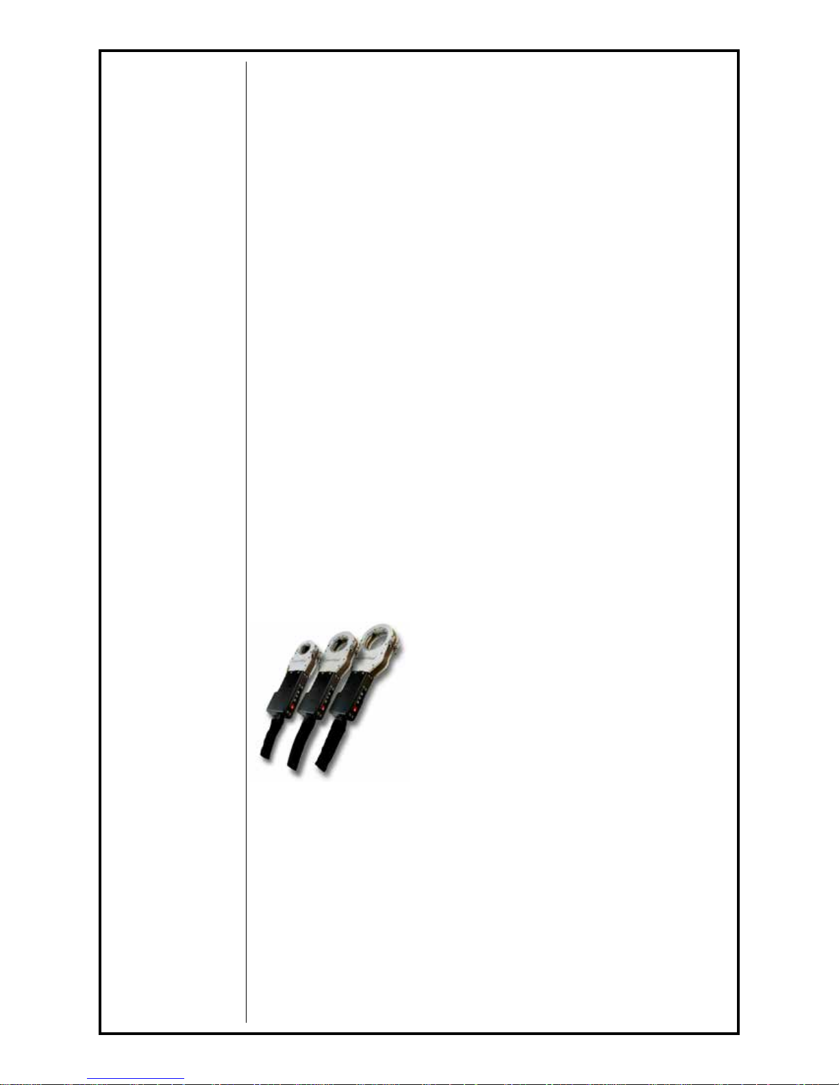
Section 3 Weldhead and Torches
For robust solutions for orbital weld applications, the CopperHeads® are ideal
cost savers for sanitary and high-pressure tube systems.
The CopperHead series are our most cost effective and rugged in-place
orbital weldheads offered in three models. The CopperHead models 5001
(1/8 - 1 inch OD), 5002 (1/4 - 2 inch OD) and 5003 (1/2 - 3 inch OD) each
offer versatility and high-output production rates.
The water-cooled, narrow prole CopperHeads are lightweight and easy to
handle for those awkward welds with limited access.
All MK weldheads can be utilized as bench mounted or remotely controlled
units.
The models and the capacities are as follows:
MODEL CAPACITY (Max. OD)
5001 1/8” - 1”
5002 1/4” - 2”
5003 1/2” - 3”
5006 2" OD - 6" OD Tube
With a simple power connector pigtail (P/N 005-
0619), all previously sold MK Orbital weldheads will
adapt to the CobraTig 150 SM. You must change the previous electrode and
ground cable connectors from the push-in type to a twist-lock type.
The order numbers for the twist-lock type are: P/N 153-0755 Electrode (male
connector to exchange for the black connector) and P/N 153-0813 Ground
(female connector to exchange for the green connector).
For MicroTig welding operations, the MicroTig Accessory Kit (P/N 005-0670)
is also available. This contains all the necessary items needed when using
the CobraTig 150 SM unit in the WELD MANUAL mode.
Precision MicroTig Technology is a standard feature of the CobraTig150 SM.
The ideal precision manual welder produces reliable, smooth arc starts at 0.5
amps and is perfect for welding precision thin wall exotic materials such as
titanium and stainless steel or ne wire sizes.
CobraTig® 150 Owner's Manual - Page 2
 Loading...