

MK Products COBRAMIG 300 Owner's Manual

Owner’s Manual
Product: CobraMIG 300
Manual: 091-0711
Serial: 1601 0001
Voltage Req'd: 240VAC-1PH, or
480VAC-1PH
Revision: -A-
Model Number: 187-001
CobraMig 300
Power Supply/
Detachable Wire Feeder

Table of Contents
Safety Considerations .......................................................................I-III
Introduction .......................................................................................................IV
Installation ............................................................................... Section A
Technical Specications ..................................................................................... 1
Power Supply Installation ................................................................................... 1
Gun Installation ..................................................................................................5
Wire Spool Installation .......................................................................................6
Input Voltage Setup ............................................................................................9
Operation .................................................................................Section B
Display Settings ...............................................................................................10
Advanced Parameters...................................................................................... 11
Process Settings ..............................................................................................13
Accessories .............................................................................Section C
Optional Kits ..................................................................................................... 14
Adapter Kits......................................................................................................15
Maintenance ............................................................................Section D
Power Supply Maintenance .............................................................................16
Troubleshooting .......................................................................Section E
Warning ............................................................................................................17
Troubleshooting Guide .....................................................................................18
Appendices .............................................................................. Section F
Diagrams / Parts List ........................................................................................ 19
Safety Warnings
Warranty

SAFETY CONSIDERATIONS
ELECTRIC ARC WELDING EQUIPMENT
CAUTION : READ BEFORE ATTEMPTING INSTALLATION, OPERATION
OR MAINTENANCE OF THIS EQUIPMENT
1-1 INTRODUCTION
This equipment is intended for ultimate
application by commercial/industrial
users and for operation by persons
trained and experienced in the use and
maintenance of welding equipment.
Operation should not be undertaken
without adequate training in the use of
such equipment. Training is available
from many public and private schools or
similar facilities.
Safe practices in the installation,
operation and maintenance of this
equipment requires proper training in
the art, a careful study of the information
provided with the equipment, and the
use of common sense. Rules for safe
use are generally provided by suppliers
of welding power sources, compressed
gas suppliers, and electrode suppliers.
Careful compliance with these rules will
promote safe use of this equipment.
The following Safety Rules cover some
of the more generally found situations.
READ THEM CAREFULLY. In case of
any doubt, obtain qualied help before
proceeding.
1-2 GENERAL PRECAUTIONS
A. Burn Prevention
ELECTRIC ARC WELDING PRODUCES
HIGH INTENSITY HEAT AND
ULTRAVIOLET RADIANT ENERGY
WHICH MAY CAUSE SERIOUS AND
PERMANENT EYE DAMAGE AND
WHICH MAY DAMAGE ANY EXPOSED
SKIN AREAS.
Wear helmet with safety goggles or
glasses with side shields underneath,
appropriate filter lenses or plates
(protected by clear cover glass). This is a
must for welding or cutting (and chipping)
to protect the eyes from radiant energy
and ying metal. Replace cover glass
when broken, pitted, or spattered.
Medical first aid and eye treatment.
First aid facilities and a qualied rst aid
person should be available for each shift
unless medical facilities are close by for
immediate treatment of ash burns of the
eyes and skin burns.
Wear protective clothing - leather (or
asbestos) gauntlet gloves, hat, and high
safety-toe shoes. Button shirt collar and
pocket aps, and wear cuess trousers
to avoid entry of sparks and slag.
Avoid oily or greasy clothing. A spark
may ignite them.
Flammable hair preparations should not
be used by persons intending to weld
or cut.
Hot metal such as electrode stubs and
work pieces should never be handled
without gloves.
Ear plugs should be worn when working
on overhead or in a conned space. A
hard hat should be worn when others
work overhead.
B. Toxic Fume Prevention
WARNING: The use of this product may
result in exposure to chemicals known
to the State of California to cause cancer
and birth defects or other reproductive
harm.
Adequate ventilation. Severe discomfort,
illness or death can result from fumes,
vapors, heat, or oxygen enrichment or
depletion that welding (or cutting) may
produce. Prevent them with adequate
ventilation. NEVER ventilate with
oxygen.
Lead-, cadmium-, zinc-, mercury-,
beryllium-bearing and similar materials,
when welded or cut, may produce harmful
concentrations of toxic fumes. Adequate
local exhaust ventilation must be used,
or each person in the area, as well as
the operator, must wear an air-supplied
respirator. For beryllium, both must be
used.
Metals coated with or containing
materials that emit toxic fumes should
not be heated unless coating is removed
form the work surface, the area is well
ventilated, or the operator wears an airsupplied respirator.
Work in a conned space only while it is
being ventilated and, if necessary, while
wearing an air-supplied respirator.
Gas leaks in a conned space should be
avoided. Leaked gas in large quantities
can change oxygen concentration
dangerously. Do not bring gas cylinders
into a conned space.
Leaving conned space, shut OFF gas
supply at source to prevent possible
accumulation of gases in the space
if downstream valves have been
accidentally opened or left open. Check
to be sure that the space is safe before
reentering it.
Vapors from chlorinated solvents can
be decomposed by the heat of the arc
(or ame) to form PHOSGENE, a highly
toxic gas, and other lung and eye irritating
products. The ultraviolet (radiant)
energy of the arc can also decompose
trichloroethylene and perchloroethylene
vapors to form phosgene. DO NOT
WELD or cut where solvent vapors can
be drawn into the welding or cutting
atmosphere or where the radiant energy
can penetrate to atmospheres containing
even minute amounts of trichloroethylene
or perchloroethylene.
C. Fire and Explosion Prevention
Causes of fire and explosion are:
combustibles reached by the arc, ame,
ying sparks, hot slag, or heated material,
misuse of compressed gases and
cylinders, and short circuits.
BE AWARE THAT ying sparks or falling
slag can pass through cracks, along
pipes, through windows or doors, and
through wall or oor openings, out of sight
of the goggled operator. Sparks can y
many feet.
To prevent res and explosion:
Keep equipment clean and operable, free
of oil, grease, and (in electrical parts) of
metallic particles that can cause short
circuits.
If combustibles are in area, do NOT weld
or cut. Move the work if practicable, to
an area free of combustibles. Avoid paint
spray rooms, dip tanks, storage areas,
ventilators. If the work cannot be moved,
move combustibles at least 35 feet away,
out of reach of sparks and heat; or protect
against ignition with suitable and snug-
tting, re-resistant covers or shields.
Walls touching combustibles on opposite
sides should not be welded on (or cut).
Walls, ceilings, and floor near work
should be protected by heat-resistant
covers or shields.
Fire watcher must be standing by with
suitable re extinguishing equipment
during and for some time after welding
or cutting if:
1. Appreciable combustibles (including
building construction) are within 35 feet.
2. Appreciable combustibles are further
than 35 feet, but can be ignited by sparks.
3. Openings (concealed or visible) in
oors or walls within 35 feet may expose
combustibles to sparks.
4. Combustibles adjacent to walls,
ceilings, roofs, or metal partitions can
be ignited by radiant or conducted heat.
Hot work permit should be obtained
before operation to ensure supervisor’s
approval that adequate precautions have
been taken.
After work is done, check that area is free
of sparks, glowing embers, and ames.
An empty container that held combustibles,
or that can produce ammable or toxic
vapors when heated, must never be
welded on or cut, unless container has
rst been cleaned in accordance with
industry standards.
This includes: a thorough steam or
caustic cleaning (or a solvent of water
washing, depending on the combustible’s
solubility), followed by purging and
inerting with nitrogen or carbon dioxide,
and using protective equipment.
Water-lling just below working level may
substitute for inerting.
A container with unknown contents
should be cleaned (see paragraph
above). Do NOT depend on sense of
smell or sight to determine if it is safe to
weld or cut.
Hollow castings or containers must be
vented before welding or cutting. They
can explode.
Explosive atmospheres. NEVER weld or
cut where the air may contain ammable
dust, gas, or liquid vapors (such as
gasoline).
D. Compressed Gas Equipment
The safe handling of compressed gas
equipment is detailed in numerous
industry publications. The following
general rules cover many of the most
common situations.
1. Pressure Regulators
Regulator relief valve is
CobraMig
Cobra® MX Owner's Manual - Page i
® 300
Owner's Manual - Page I

designed to protect only the regulator
from overpressure; it is not intended
to protect any downstream equipment.
Provide such protection with one or more
relief devices.
Never connect a regulator to a cylinder
containing gas other than that for which
the regulator was designed.
Remove faulty regulator from service
immediately for repair (rst close cylinder
valve). The following symptoms indicate
a faulty regulator:
Leaks - if gas leaks externally.
Excessive Creep - if delivery pressure
continues to rise with downstream valve
closed.
Faulty Gauge - if gauge pointer does not
move o stop pin when pressurized, nor
returns to stop pin after pressure release.
Repair. Do NOT attempt repair.
Send faulty regulators for repair to
manufacturer’s designated repair center,
where special techniques and tools are
used by trained personnel.
2. Cylinders
Cylinders must be handled carefully to
prevent leaks and damage to their walls,
valves, or safety devices:
Avoid electrical circuit contact with
cylinders including third rails, electrical
wires, or welding circuits. They can
produced short circuit arcs that may lead
to a serious accident. (See 1-3C)
ICC or DOT marking must be on each
cylinder. It is an assurance of safety when
the cylinder is properly handled.
Identifying gas content. Use only cylinders
with name of gas marked on them; do not
rely on color to identify gas content. Notify
supplier if unmarked. NEVER DEFACE
or alter name, number, or other markings
on a cylinder. It is illegal and hazardous.
Empties: Keep valves closed, replace
caps securely; mark MT; keep them
separate from FULLS, and return
promptly.
Prohibited use. Never use a cylinder or its
contents for other than its intended use,
NEVER as a support or roller.
Locate or secure cylinders so they cannot
be knocked over.
Passageways and work areas. Keep
cylinders clear of areas where they may
be stuck.
Transporting cylinders. With a crane,
use a secure support such as a platform
or cradle. Do NOT lift cylinders o the
ground by their valves or caps, or by
chains, slings, or magnets.
Do NOT expose cylinders to excessive
heat, sparks, slag, and ame, etc. that
may cause rupture. Do not allow contents
to exceed 55 degrees C (130 degrees
F.) Cool with water spray where such
exposure exists.
Protect cylinders, particularly valves from
bumps, falls, falling objects, and weather.
Replace caps securely when moving
cylinders.
Stuck valve. Do NOT use a hammer
or wrench to open a cylinder valve that
cannot be opened by hand. Notify your
supplier.
Mixing gases. NEVER try to mix any
gases in a cylinder.
NEVER rell any cylinder.
Cylinder ttings should never be modied
or exchanged.
3. Hose
Prohibited use. Never use hose other
than that designed for the specied gas.
A general hose identication rule is: red
for fuel gas, green for oxygen, and black
for inert gases.
Use ferrules or clamps designed for
the hose (not ordinary wire or other
substitute) as a binding to connect hoses
to ttings.
No copper tubing splices. Use only
standard brass ttings to splice hose.
Avoid long runs to prevent kinks and
abuse. Suspend hose o ground to keep
it from being run over, stepped on, or
otherwise damaged.
Coil excess hose to prevent kinks and
tangles.
Protect hose from damage by sharp
edges, and by sparks, slag, and open
ame.
Examine hose regularly for leaks,
wear, and loose connections. Immerse
pressured hose in water; bubbles
indicate leaks
Repair leaky or worn hose by cutting area
out and splicing. Do NOT use tape.
4. Proper Connections
Clean cylinder valve outlet of impurities
that may clog orices and damage seats
before connecting regulator. Except
for hydrogen, crack valve momentarily,
pointing outlet away from people and
sources of ignition. Wipe with a clean,
lintless cloth.
Match regulator to cylinder. Before
connecting, check that the regulator label
and cylinder marking agree, and that the
regulator inlet and cylinder outlet match.
NEVER Connect a regulator designed
for a particular gas or gases to a cylinder
containing any other gas.
Tighten connections. When assembling
threaded connections, clean and smooth
seats where necessary. Tighten. If
connection leaks, disassemble, clean,
and retighten, using properly fitting
wrench.
Adapters. Use a CGA adapter (available
from your supplier) between cylinder
and regulator, if one is required. Use
two wrenches to tighten adapter marked
RIGHT and LEFT HAND threads.
Regulator outlet (or hose) connections
may be identied by right hand threads
for oxygen and left hand threads (with
grooved hex on nut or shank) for fuel gas.
5. Pressurizing Steps:
Drain regulator of residual gas through
suitable vent before opening cylinder
(or manifold valve) by turning adjusting
screw in (clockwise). Draining prevents
excessive compression heat at high
pressure seat by allowing seat to open
on pressurization. Leave adjusting
screw engaged slightly on single-stage
regulators.
Stand to side of regulator while opening
cylinder valve.
Open cylinder valve slowly so that
regulator pressure increases slowly.
When gauge is pressurized (gauge
reaches regulator maximum) leave
cylinder valve in following position: for
oxygen and inert gases, open fully to seal
stem against possible leak; for fuel gas,
open to less than one turn to permit quick
emergency shut-o.
Use pressure charts (available from
your supplier) for safe and efficient
recommended pressure settings on
regulators.
Check for leaks on rst pressurization
and regularly thereafter. Brush with soap
solution. Bubbles indicate leaks. Clean
o soapy water after test; dried soap is
combustible.
E. User Responsibilities
Follow all Safety Rules.
Remove leaky or defective equipment
from service immediately for repair. Read
and follow user manual instructions.
F. Leaving Equipment Unattended
Close gas supply at source and drain gas.
G. Rope Staging-Support
Rope staging-support should not be used
for welding or cutting operation; rope
may burn.
1-3 ARC WELDING
Comply with precautions in 1-1, 1-2, and
this section. Arc Welding, properly done,
is a safe process, but a careless operator
invites trouble. The equipment carries
high currents at signicant voltages.
The arc is very bright and hot. Sparks
y, fumes rise, ultraviolet and infrared
energy radiates, weldments are hot, and
compressed gases may be used. The
wise operator avoids unnecessary risks
and protects himself and others from
accidents.
A. Burn Protection
Comply with precautions in 1-2.
The welding arc is intense and visibly
bright. Its radiation can damage eyes,
penetrate lightweight clothing, reect
from light-colored surfaces, and burn
the skin and eyes. Skin burns resemble
acute sunburn; those from gas-shielded
arcs are more severe and painful.
DON’T GET BURNED; COMPLY WITH
PRECAUTIONS.
1. Protective Clothing
Wear long-sleeve clothing in addition to
gloves, hat, and shoes. As necessary,
use additional protective clothing such
CobraMig
Cobra® MX Owner's Manual - Page ii
® 300
Owner's Manual - Page II

as leather jacket or sleeves, ameproof
apron, and re-resistant leggings. Avoid
outer garments of untreated cotton.
Bare skin protection. Wear dark,
substantial clothing. Button collar to
protect chest and neck, and button
pockets to prevent entry of sparks.
2. Eye and Head Protection
Protect eyes from exposure to arc. Eyes
may be damaged by radiant energy
when exposed to the electric arc, even
when not looking in the direction of the
arc. Never look at an electric arc without
protection.
Welding helmet or shield containing a
lter plate shade no. 12 or denser must
be used when welding. Place over face
before striking arc.
Protect lter plate with a clear cover plate.
Cracked or broken helmet or shield
should NOT be worn; radiation can be
passed through to cause burns.
Cracked, broken, or loose lter plates
must be replaced IMMEDIATELY.
Replace clear cover plate when broken,
pitted, or spattered.
Flash goggles with side shields MUST
be worn under the helmet to give some
protection to the eyes should the helmet
not be lowered over the face before an arc
is struck. Looking at an arc momentarily
with unprotected eyes (particularly a high
intensity gas-shielded arc) can cause a
retinal burn that may leave a permanent
dark area in the eld of vision.
3. Protection of Nearby Personnel
Enclose the welding area. For production
welding, a separate room or enclosed
bay is best. In open areas, surround
the operation with low-reflective,
noncombustible screens or panels.
Allow for free air circulation, particularly
at oor level.
Viewing the weld. Provide face shields
for all persons who will be looking directly
at the weld.
Others working in area. See that all
persons are wearing ash goggles.
Before starting to weld, make sure that
screen aps or bay doors are closed.
B. Toxic Fume Prevention
Comply with precautions in 1-2B.
Generator engine exhaust must be
vented to the outside air. Carbon
monoxide can kill.
C. Fire and Explosion Prevention
Comply with precautions in 1-2C.
Equipment’s rated capacity. Do not
overload arc welding equipment. It may
overheat cables and cause a re.
Loose cable connections may overheat
or ash and cause are.
Never strike an arc on a cylinder or other
pressure vessel. It creates a brittle
area that can cause a violent rupture or
lead to such a rupture later under rough
handling.
D. Compressed Gas
Equipment
Comply with precautions in 1-2D.
E. Shock Prevention
Exposed electrically hot conductors or
other bare metal in the welding circuit,
or in ungrounded, electrically-HOT
equipment can fatally shock a person
whose body becomes a conductor. DO
NOT STAND, SIT, LIE, LEAN ON, OR
TOUCH a wet surface when welding
without suitable protection.
To protect against shock:
Keep body and clothing dry. Never
work in damp area without adequate
insulation against electrical shock. Stay
on a dry duckboard, or rubber mat when
dampness or sweat cannot be avoided.
Sweat, sea water, or moisture between
body and an electrically HOT part - or
grounded metal - reduces the body
surface electrical resistance, enabling
dangerous and possibly lethal currents
to ow through the body.
1. Grounding the Equipment
When installing, connect the frames of
each unit such as welding power source,
control, work table, and water circulator
to the building ground. Conductors must
be adequate to carry ground currents
safely. Equipment made electrically HOT
by stray currents may shock, possibly
fatally. Do NOT GROUND to electrical
conduit, or to a pipe carrying ANY gas
or a ammable liquid such as oil or fuel.
Three-phase connection. Check phase
requirement of equipment before
installing. If only three-phase power
is available, connect single-phase
equipment to only two wires of the
three-phase line. Do NOT connect
the equipment ground lead to the third
(live) wire, or the equipment will become
electrically HOT - a dangerous condition
that can shock, possibly fatally.
Before welding, check ground for
continuity. Be sure conductors are
touching bare metal of equipment frames
at connections.
If a line cord with a ground lead is provided
with the equipment for connection to a
switch box, connect the ground lead to
the grounded switch box. If a threeprong plug is added for connection to a
grounded mating receptacle, the ground
lead must be connected to the ground
prong only. If the line cord comes with a
three-prong plug, connect to a grounded
mating receptacle. Never remove the
ground prong from a plug, or use a plug
with a broken ground prong.
2. Connectors
Fully insulated lock-type connectors
should be used to join welding cable
lengths.
3. Cables
Frequently inspect cables for wear,
cracks, and damage. IMMEDIATELY
REPLACE those with excessively worn
or damaged insulation to avoid possibly
lethal shock from bared cable. Cables
with damaged areas may be taped to give
resistance equivalent to original cable.
Keep cable dry, free of oil and grease,
and protected from hot metal and sparks.
4. Terminals and Other Exposed Parts
Terminals and other exposed parts of
electrical units should have insulating
covers secured before operation.
5. Electrode Wire
Electrode wire becomes electrically HOT
when the power switch of gas metal-arc
welding equipment is ON and welding
gun trigger is pressed. Keep hands and
body clear of wire and other HOT parts.
6. Safety Devices
Safety devices such as interlocks
and circuit breakers should not be
disconnected or shunted out.
Before installation, inspection, or service
of equipment, shut OFF all power, and
remove line fuses (or lock or red-tag
switches) to prevent accidental turning
ON of power. Disconnect all cables from
welding power source, and pull all 115
volts line-cord plugs.
Do not open power circuit or change
polarity while welding. If, in an emergency,
it must be disconnected, guard against
shock burns or ash from switch arcing.
Leaving equipment unattended. Always
shut OFF, and disconnect all power to
equipment.
Power disconnect switch must be
available near the welding power source.
CobraMig
Cobra® MX Owner's Manual - Page iii
® 300
Owner's Manual - Page III

Introduction
Thank you for purchasing what we believe is the best built wire feeder/power
supply on the market. MK Products is family owned, operated and has been
the leader in aluminum push/pull technology for the past 50 years.
This manual details the installation of your CobraMig 300. Properly installed,
adjusted, and maintained, it will prove to be a reliable welding system
producing consistent uniform welds for years to come.
The CobraMig 300 unit consists of a single-phase constant voltage (CV)
power supply with a removable push-pull wire feeder and controls. This unit
is directly compatible with all of MK Products 14 pin X-Series digital push-pull
guns or our 7 pin "W" clocked anolog guns using an adapter kit (005-0784).
In order to assure optimum performance of your CobraMig 300, familiarize
yourself with the contents of this manual, and carefully follow all instructions.
This manual will not only guide you in installing your CobraMig 300, but
will also be a handy reference for optional items, replacement parts, and
consumables.
Visit our website for a digital copy of this manual, www.mkprod.com.
Section A Installation
Technical Specications
Wire Diameter Capacity
-.030" - 1/16" (0.8mm - 1.6mm) aluminum wire
-.030" - .045" (0.8mm - 1.2mm) solid or ux-cored steel and stainless
steel wire
Wire Capacity
-12" Diameter Spool
-Bulk Wire Drum using optional adapter kit 005-0786
Power Input
-240 VAC 60Hz, 50A, Single Phase
-480 VAC 60Hz, 30A, Single Phase
Duty Cycle - 60% @:
-300A @ 30 VDC - (9.0KW), No Load 40 VDC max OCV
Weight
-245 lbs (dry), 275 lbs (shipping)
Size
-18.5"W x 34.5"H x 36"L
For use with the Following Guns
-Digital 14 pin- Python X, Cobra X, Prince X
-Analog 7 pin "W" clocked with adapter kit 005-0784- Python,
Python LX, Cobra MX, Cobra Max, Cobra SX, Cobra Gold,
Cobra System III, Prince, Prince XL, RoboKing
Power Supply Installation
Step 1; Out of the box
Tools needed:
• 1/2” wrench
• Phillips screw driver
Uncrate CobraMig 300:
• remove box covering welder
• remove lag bolts from rear platform holding
down welder with 1/2” wrench
• remove security bracket from bottom front of
welder with Phillips screwdriver
• unit will now be available to remove from
shipping pallet
* 2 people are required to lift welder from
shipping pallet (approx. 250 lbs.)
DO NOT use handle on top for lifting
Permanent damage or serious injury may
occur *
CobraMig
® 300
Owner's Manual - Page 1
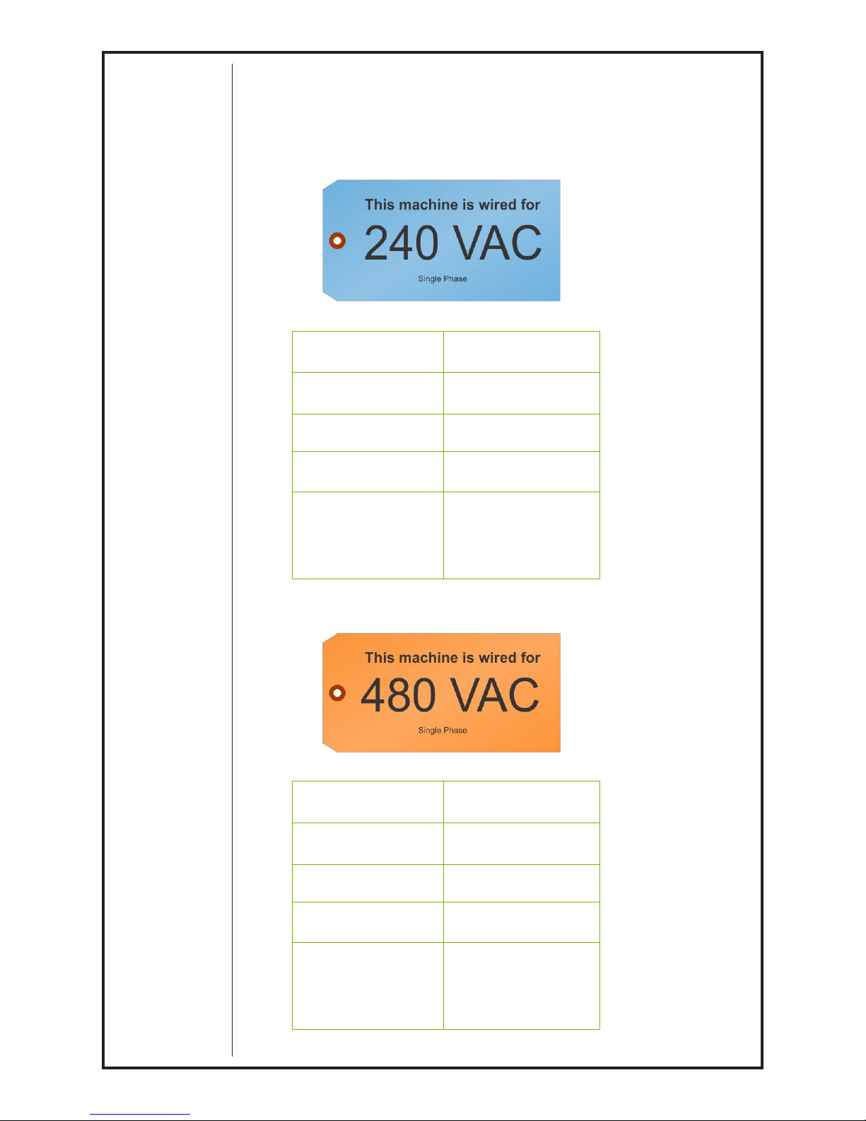
Refer to tag to designate how your unit is wired. If
you nd it necessary to change the input voltage see
page 9, Input Voltage Setup.
VOLTAGE 240
PHASE SINGLE
CURRENT
FREQUENCY
DUTY
50 AMPS
50 / 60 Hz
100% @ 225 AMPS
60% @ 300 AMPS
CYCLE
VOLTAGE 480
PHASE SINGLE
CURRENT
FREQUENCY
DUTY
30 AMPS
50 / 60 Hz
100% @ 225 AMPS
60% @ 300 AMPS
CYCLE
CobraMig
® 300
Owner's Manual - Page 2
WARNING
Copper
Size Ga.
240 50 Amp No. 8 No. 8
480 30 Amp No. 8 No. 8
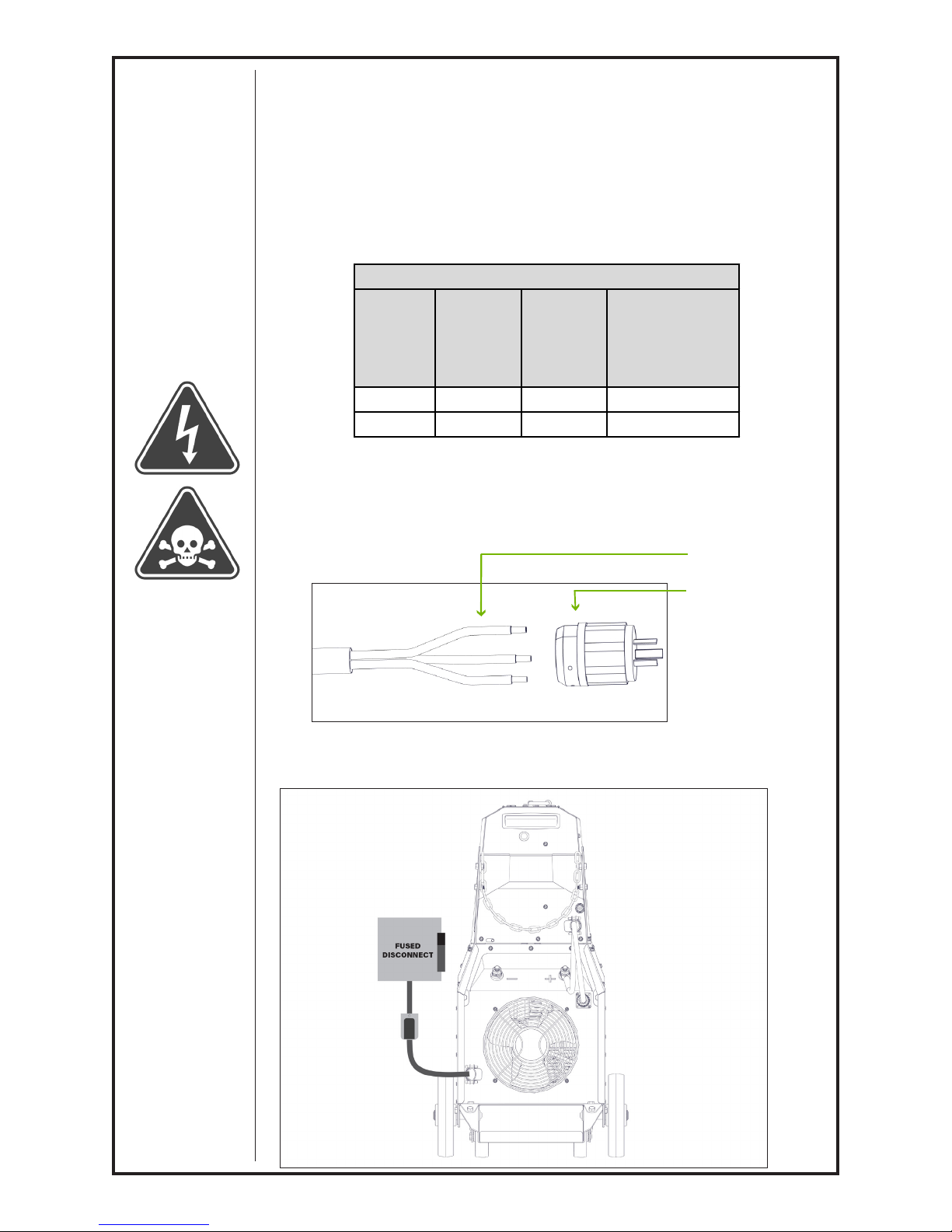
Conductor and Fuse Guide
Turn OFF input power using the disconnect switch at the fuse
box before working on equipment. Install equipment in ac-
cordance with the U.S National Electrical Code, all local codes
and the manufacture’s recommendations. A fused line discon-
nect switch should be installed in the input circuit to the unit.
Failure to comply with this warning can result in serious
injury or death
Line
Voltage
Approx.
Line Fuse
Rating
Copper
Line Wire
Size Ga.
Grounding
Conductor Min.
Step 2: Single Phase Electrical Plug
Wire an appropriate electrical plug to the provided power cord.
Power Cord
Electrical Plug
(not supplied)
Step 3: Connect to Power
Plug the welder power cord into a single phase fused
power outlet.
CobraMig
® 300
Owner's Manual - Page 3

Step 4: Ground Cable
Attach a ground cable to the negative post on the back
of the power supply.
Step 5: Inlet Gas Connection
Connect a regulator/owmeter and gas line to the inlet
in the back of the wire feeder, typically set to 20-30
CFH.
CobraMig
® 300
Owner's Manual - Page 4

Gun Installation
Step 1. Connect Your Gun
Loosen power pin connection
knob.
Install power pin connection
of the gun. Verify the handle
orientation is correct to not
interfere with the sheet metal.
Tighten power pin connection
knob
Step 2. Connect 14-pin
Circular connector
Connect the 14-pin Circular
connector to the front panel of
wire feeder.
Align keys and tighten threaded
collar until locked
CobraMig
® 300
Owner's Manual - Page 5
 Loading...