

Page 1

www.mkdiamond.com
SINGLE DISC GRINDER
OWNER'S MANUAL
OPERATING INSTRUCTIONS
SDG-101
SDG-103
SDG-101
Revision 104
Manual 170103
Caution: Read all safety and operating instructions
before using this equipment. This parts list MUST
accompany the equipment at all times.
06.2014
SDG-103
Page 2
INTRODUCTION
Congratulations on your purchase of a SDG Grinder. We are certain that you will be pleased
with your purchase. MK Diamond takes pride in producing the nest construction power tools
in the industry.
Operated correctly, your SDG Grinder should provide you with years of service. In order to help
you, we have included this manual. This owners manual contains information necessary to
operate and maintain your SDG Grinder safely and correctly. Please take the time to familiarize
yourself with the SDG Grinder by reading and reviewing this manual.
Read and follow all safety, operating and maintenance instructions.
If you should have questions concerning your SDG Grinder, please feel free to call our friendly
customer service department at: 800 421-5830.
Regards,
MK Diamond
NOTE THIS INFORMATION FOR FUTURE USE:
MODEL NUMBER:
SERIAL NUMBER:
PURCHASE PLACE:
PURCHASE DATE:
NOTE: For your (1) one year warranty to be effective, complete the warranty card
(including the Serial Number) and mail it in as soon as possible.
2
Page 3

TABLE OF CONTENTS
SAFETY
Safety Messages 4
Damage Prevention Message 4
General Safety Precautions
Rules for Safe Operation 5
California Proposition 65 Message 6
Hazard Symbols 7
Electrical Requirements 8-10
Safety Label Locations 11
Product Specications 12
UNPACKING and TRANSPORT
Unpacking 13
Contents 13
Transport 13
ASSEMBLY and OPERATION
Handlebar Adjustment 14
Grinding Discs Installation 14
Grinding 15
Wheel adjustment 15
Shroud 16
MAINTENANCE AND TROUBLESHOOTING
Cleanup 17
Maintenance 17
Troubleshooting 18
ACCESSORIES ORDERING and RETURN INSTRUCTIONS
Accessories 19
Ordering Information 22
Return Material Policy 22
Packaging Instructions 22
Authorized Service Centers 22
CONTACT AND LIMITED WARRANTY
Contact 23
Limited Warranty 23
3
Page 4
SDG SAFETY
Read and follow all safety, operating and maintenance instructions. Failure to read and follow
these instructions could result in injury or death to you or others. Failure to read and follow these
instructions could also result in damage and/or reduced equipment life.
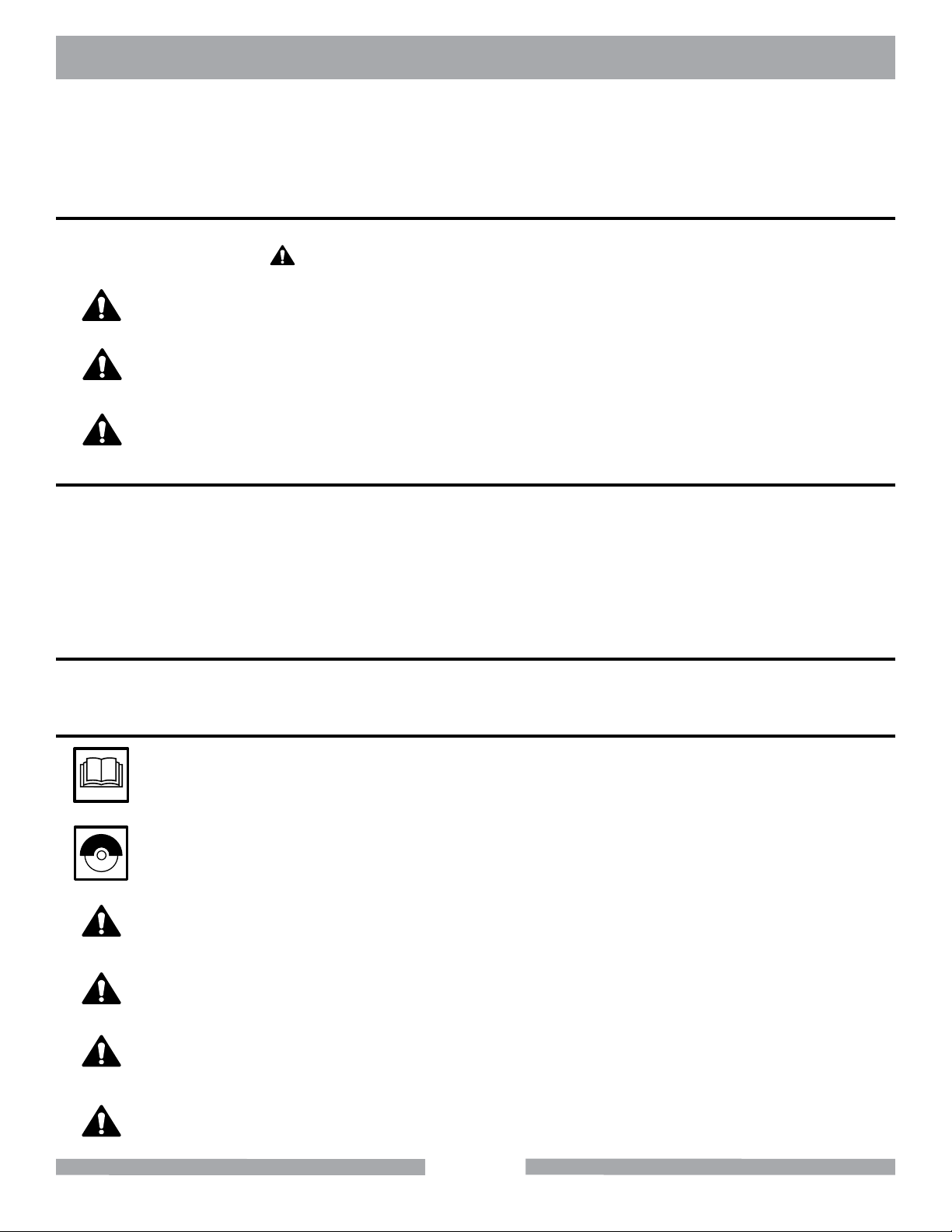
SAFETY MESSAGES
A safety message alerts you to potential hazards that could hurt you or others. Each safety message is preceded by a safety alert symbol ( ) and one of three words: DANGER, WARNING, or CAUTION.
DANGER
WARNING
CAUTION
You WILL be KILLED or SERIOUSLY INJURED if you do not follow directions.
You CAN be KILLED or SERIOUSLY INJURED if you do not follow directions.
You CAN be INJURED if you do not follow directions. It may also be used to alert
against unsafe practices.
DAMAGE PREVENTION AND INFORMATION MESSAGES
A Damage Prevention Message is to inform the user of important information and/or instructions that
could lead to equipment or other property damage if not followed. Information Messages convey
information that pertains to the equipment being used. Each message will be preceded by the word
NOTE, as in the example below.
NOTE:
Equipment and/or property damage may result if these instructions are not followed.
GENERAL SAFETY PRECAUTIONS AND HAZARD SYMBOLS
In order to prevent injury, the following safety precautions and symbols should be followed at all times!
SAFETY PRECAUTIONS
ALWAYS read the Owner’s Manual before operating the machine.
ALWAYS keep the Shroud in place.
REMOVE ADJUSTING KEYS AND WRENCHES
Form a habit of checking to see that keys and adjusting wrenches are removed from
the power tool before it is turned on.
KEEP WORK AREA CLEAN
Cluttered work areas and benches invite accidents.
DO NOT USE IN DANGEROUS PLACES
DO NOT use power tools in damp or wet locations nor expose them to rain. Always
keep the work area well lighted.
KEEP CHILDREN AWAY
All visitors and children should be kept a safe distance from work area.
4
Page 5
SDG SAFETY
MAKE THE WORKSHOP KID PROOF
Make the workshops kid proof by using padlocks, master switches or by removing starter
keys.
DO NOT FORCE THE TOOL
A power tool will do a job better and safer operating at the rate for which it was designed.
USE THE RIGHT TOOL
DO NOT force a tool or an attachment, to do a job that it was not designed to do.
USE THE PROPER EXTENSION CORD
If using an extension cord make sure it is in good condition first. When using an extension
cord, be sure to use one heavy enough to carry the current your product will draw. An
undersized cord will cause a drop in line voltage that will result in a loss of power and
overheating. TABLE 1, Page 10 shows the correct AWG size to use depending on cord
length and nameplate ampere rating. If in doubt, use the next heavier gage. The smaller
the gage number, the heavier the cord.
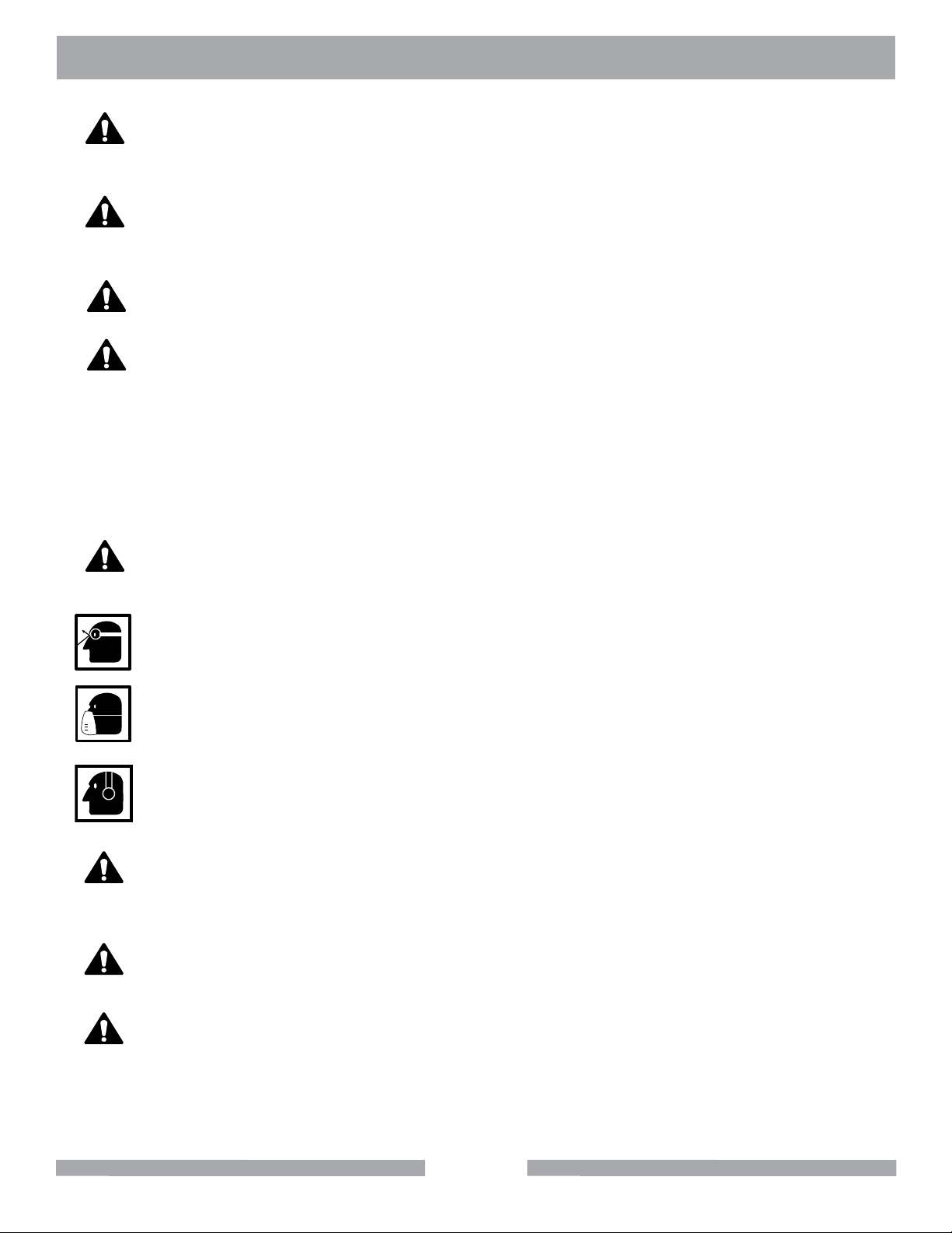
USE PROPER APPAREL
DO NOT wear loose clothing, gloves, neckties, rings, bracelets, or other jewelry that may
be caught in moving parts. Non-slip footwear is recommended. Wear protective hair
covering to contain long hair.
ALWAYS wear approved eye protection.
ALWAYS wear approved respiratory protection.
ALWAYS use hearing protection.
SECURE WORK
Clamps or a vise should be used to hold work whenever practical. Keeping your
hands free to operate a power tool is safer.
DO NOT OVERREACH
Keep proper footing and balance at all times by not overreaching.
MAINTAIN TOOLS WITH CARE
Keep tools clean for the best and safest performance. Always follow maintenance
instructions for lubricating, and when changing accessories.
5
Page 6
(
(
)
)
SDG SAFETY
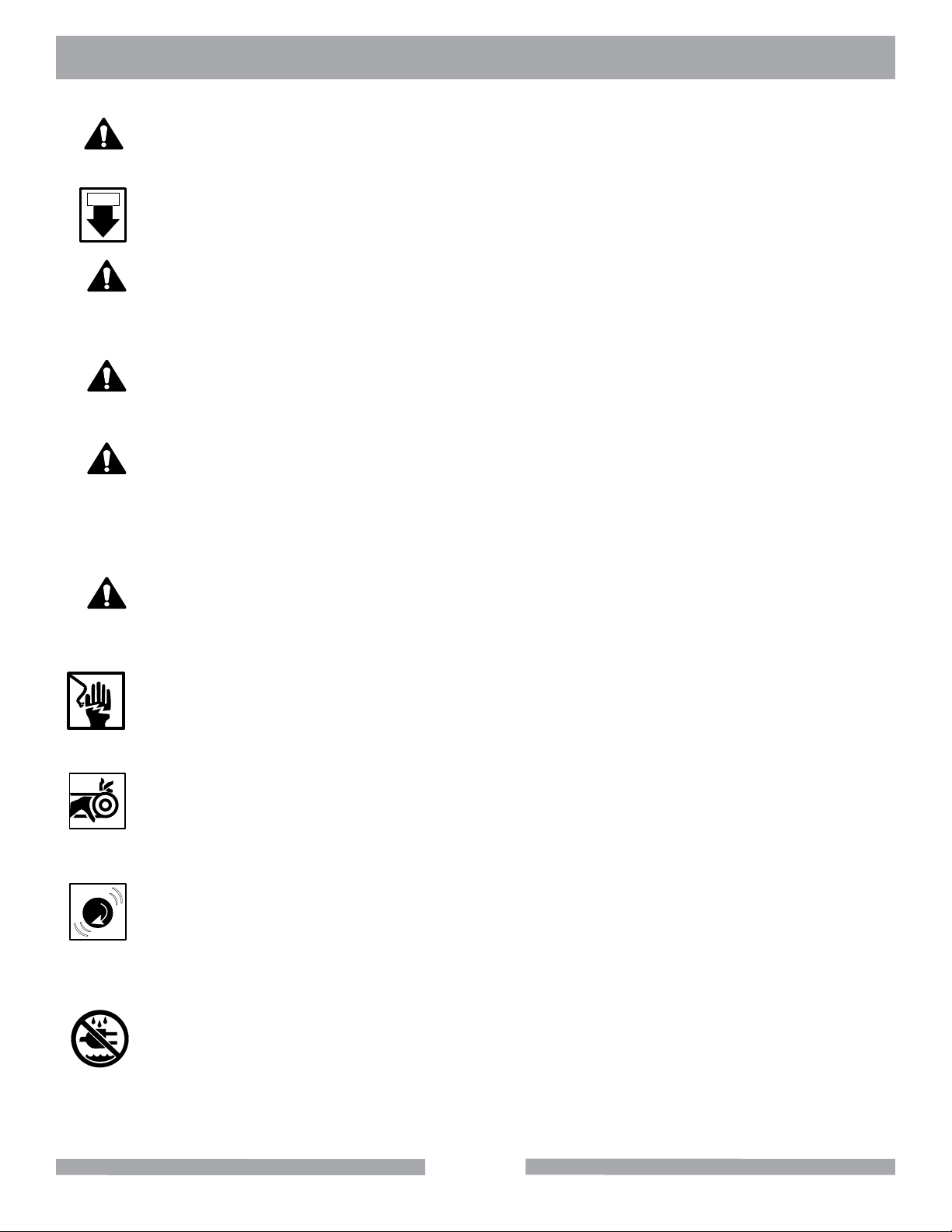
DISCONNECT TOOLS
Power tools should always be disconnected before servicing or when changing
accessories, such as blades, bits, cutters, and the like.
ON / OFF
ALWAYS place the power ON/OFF switch in the OFF position when the saw is not in use.
USE RECOMMENDED ACCESSORIES
Consult the owner’s manual for recommended accessories. Using improper accessories
may increase the risk of personal or by-stander injury.
NEVER STAND ON THE TOOL
Serious injury could occur if a power tool is tipped, or if a cutting tool is unintentionally
contacted.
CHECK FOR DAMAGED PARTS
Before using a power tool, check for damaged part. A guard or any other part that is
damaged should be carefully checked to determine if would operate properly and perform
its intended function. Always check moving parts for proper alignment or binding. Check
for broken parts and mountings and all other conditions that may affect the operation of
the power tool. A guard, or any damaged part, should be properly repaired or replaced.
NEVER LEAVE A TOOL UNATTENDED
TURN POWER OFF - Do not leave a tool until it comes to a complete stop. Always
turn a power tool OFF when leaving the work area, or, when a cut is finished.
ELECTRICAL SHOCK
NEVER touch electrical wires or components while the motor is running. They can be
sources of electrical shock which could cause severe injury or burns.
ROTATING PARTS
Keep hands, feet, hair, and clothing away from all moving parts to prevent injury.
Never operate the motor with covers, shrouds, or guards removed.
OVER SPEED
NEVER tamper with the governor components or settings to increase the maximum
speed. Severe personal injury and damage to the motor or equipment can result if
operated at speeds above maximum.
DO NOT EXPOSE TO RAIN
DO NOT expose to rain or use in damp locations.
6
Page 7

SDG SAFETY
ON
(
(
)
)
SILICA DUST WARNING
Grinding/cutting/drilling of masonry, concrete, metal and other materials with silica in their composition
may give off dust or mists containing crystalline silica. Silica is a basic component of sand, quartz,
brick clay, granite and numerous other minerals and rocks. Repeated and/or substantial inhalation of
airborne crystalline silica can cause serious or fatal respiratory diseases, including silicosis. In addition, California and some other authorities have listed respirable crystalline silica as a substance
known to cause cancer. When cutting such materials, always follow respiratory precautions.
Use appropriate NIOSH-approved respiratory protection where dust hazard may occur. Paper masks
or surgical masks without a NIOSH approval number are not recommended because they do little to
protect the worker. For more information about respirator programs, including what respirators have
received NIOSH approval as safe and effective, please visit the NIOSH website at:
http://www.cdc.gov/niosh/topics/respirators
Observe OSHA regulations for respirator use (29 C.F.R.§1910.134).
Visit http://www.osha.gov for more information.
CALIFORNIA PROPOSITION 65 MESSAGE
Some dust created by power sanding, sawing, grinding, drilling, and other construction activities contain chemicals known (to the State of California) to cause cancer, birth defects or other reproductive
harm. Some examples of these chemicals are:
• Lead, from lead-based paints
• Crystalline silica from bricks, cement and other masonry products
• Arsenic and chromium, from chemically treated lumber
For further information, consult the following sources:
http://www.osha.gov/dsg/topics/silicacrystalline/index.html
http://www.cdc.gov/niosh/docs/96-112/
http://oehha.ca.gov/prop65/law/P65law72003.html
http://www.dir.ca.gov/Title8/sub4.html
Your risk from these exposures varies depending on how often you do this type of work. To reduce
your exposure to these chemicals, work in a well-ventilated area, and work with approved safety
equipment, such as dust masks that are specially designed to lter out microscopic particles. Where
use of a dust extraction device is possible, it should be used. To achieve a high level of dust collection, use an industrial HEPA vacuum cleaner. Observe OSHA 29 CFR part 1926.57 and 1926.103.
WARNING
Sawing, grinding and drilling generate dust. Excessive airborne particles may cause irritation to eyes,
skin and respiratory tract. To avoid breathing impairment, always employ dust controls and protection
suitable to the material being sawed or drilled; See OSHA (29 CFR Part 1910.1200).
7
Page 8
SDG SAFETY
ELECTRICAL REQUIREMENTS AND GROUNDING INSTRUCTIONS
In order to prevent potential electrical shock and injury, the following electrical safety precautions and
symbols should be followed at all times!
WARNING
In case of a malfunction or breakdown, grounding provides a path of least resistance for electric current to reduce the risk of electric shock. This tool is equipped with an electric cord having an equipment-grounding conductor and a grounding plug. The plug must be plugged into a matching outlet
that is properly installed and grounded in accordance with all local codes and ordinances.
• Do not modify the plug provided – if it will not t the outlet; have the proper outlet installed by a
qualied electrician
• Improper connections of the equipment-grounding conductor can result in a risk of electric
shock. The equipment-grounding conductor is the insulated conductor that has an outer
surface that is green, with or without yellow stripes. If repair or replacement of the electric cord
or plug is necessary, do not connect the equipment-grounding conductor to a live terminal
• Check with a qualied electrician or service personnel if the grounding instructions are not
completely understood, or if in doubt as to whether the tool is properly grounded
• Use only 3-wire extension cords that have 3-prong grounding plugs and 3-pole receptacles that
accept the tool’s plug
• Repair or replace a damaged or worn cord immediately
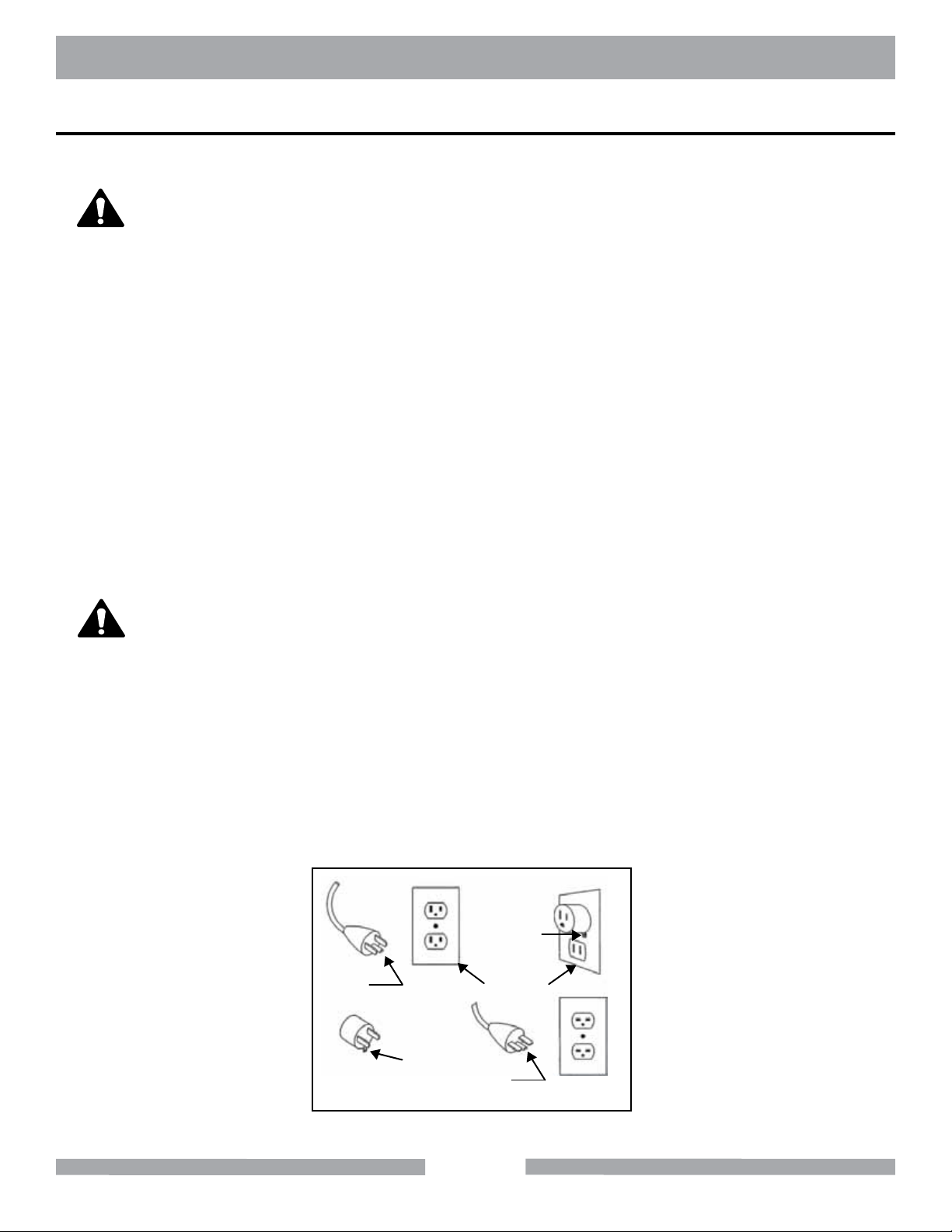
WARNING
This tool is intended for use on a circuit that has an outlet that looks like the one shown in Sketch A.
The tool has a grounding plug that looks like the plug illustrated in Sketch A. A temporary adapter,
which looks like the adapter illustrated in sketches B and C, may be used to connect this plug to a
2-pole receptacle as shown in Sketch B, if a properly grounded outlet is not available. The temporary
adapter should be used only until a properly grounded outlet can be installed by a qualied electrician. The green-colored rigid ear, lug, and the like, extending from the adapter, must be connected
to a permanent ground such as a properly grounded outlet box.
NOTE: Use of a temporary adapter is not permitted in Canada.
Metal Screw
Grounding
Pin
(A)
ADAPTER
Grounding
Means
(C)
Cover of
Grounded
Outlet Box
Grounding
Pin
(B)
(D)
Circuit and Adapter Information
8
Page 9

SDG SAFETY
WARNING
To avoid the possibility of the appliance plug or receptacle getting wet, position the machine to one
side of a wall mounted receptacle. This will prevent water from dripping onto the receptacle or plug. A
“drip loop,” should be arranged by the user to properly position the power cord relative to the power source.
The “drip loop” is that part of the cord below the level of the receptacle, or the connector, if an extension cord is used. This method of positioning the cord prevents water traveling along the power cord
and coming in contact with the receptacle.
If the plug or receptacle gets wet, DO NOT unplug the cord. Disconnect the fuse or circuit breaker
that supplies power to the tool. Then unplug and examine for presence of water in the receptacle.
WARNING
Use only extension cords that are intended for outdoor use. These extension cords are
identified by a marking “Acceptable for use with outdoor appliances; store indoors while
not in use." Use only extension cords having an electrical rating not less than the rating
of the product. Do not use damaged extension cords. Examine extension cords before
using and replace if damaged. Do not abuse extension cords and do not yank on any
cord to disconnect. Do not allow the cord to come in contact with the grinding head/
wheel or other moving parts of the machine. Keep cords away from heat and sharp
edges. Always disconnect the extension cord from the receptacle before disconnecting
the product from the extension cord.
WARNING
To reduce the risk of electrocution, keep all connections dry and off the ground. Do not
touch the plug with wet hands.
9
Page 10

SDG SAFETY
WARNING
Use of under sized extension cords result in low voltage to the motor that can result in
motor burnout and premature failure. MK Diamond warns that equipment returned to
us showing signs of being run in a low voltage condition, through the use of undersized
extension cords will be repaired or replaced totally at the customer's expense. There will
be no warranty claim.
To choose the proper extension cord,
• Locate the length of extension cord needed in the table below.
• Once the proper length is found, move down the column to obtain the correct AWG
size required for that length of extension cord.
EXTENSION CORD LENGTH
Nameplate
Amperes
0 - 5 16 16 16 14 12 12
115V 25' 50' 75' 100' 150' 200'
250V 50' 100' 150' 200' 300' 400'
5.1 - 8 16 16 14 12 10 •
8.1 - 12 14 14 12 10 • •
12.1 - 15 12 12 10 10 • •
15.1 - 20 10 10 10 • • •
10
Page 11

SDG SAFETY
OPERATION & SAFETY DECALS
The SDG is equipped with a number of safety decals. These decals are provided for operator safety
and maintenance information. Should any of these operation or safety decals become unreadable,
replacements can be obtained by calling (800) 262-1575.
Not Shown
!
WARNING
Grinding/cutting/drilling of masonry, concrete, metal and other materials with silica in
their composition may give off dust or mists containing crystalline silica. Silica is a basic
component of sand, quartz, brick clay, granite and numerous other minerals and rocks.
Repeated and/or substantial inhalation of airborne crystalline silica can cause serious
or fatal respiratory diseases, including silicosis. In addition, California and some other
authorities have listed respirable crystalline silica as a substance known to cause cancer.
Label A
CAUTION
!
Keep
hands and
feet clear.
Label C
FOR INFORMATION ON
SERVICE OR
WARRANTY
PLEASE CALL
1-800-474-5594
Label D Label E
!
WARNING
DO NOT operate
this equipment
before reading
the owner’s
manual!
Label B
For manuals and parts
CAUTION
!
PINCH POINT
Can cause severe
personal injury
lists scan the QR code
with your smart phone
Label F
Label Sheet Part# 166010
F
A
B
E
D
11
Page 12

SDG PRODUCT SPECIFICATIONS
PRODUCT SPECIFICATIONS
The SDG is a versatile unit. Operated and used according to this manual, the SDG will
provide years of dependable service.
FEATURES
• Uses either a 10 or 20 segment 10" diameter diamond grinding discs to level, smooth or
clean the top surface of concrete slabs.
• Provides a smoother finish compared to other methods such as scarifiers.
• Dust shroud helps contain grinding debris.
• Works on concrete slabs, terrazzo, brick, stone and ceramic tile floors.
• The unique shroud system automatically adjusting to suit segment height and floor angle.
SPECIFICATIONS
Specifications for the SDG are listed in the table below.
Model ST-SDG-101
Power 110V/230V 1-Phase 230V 3-Phase
Amps 12.8/6.4 8.06
Horsepower 1 Hp 3 HP
Disc RPM 1725 1740
Disc Capacity 10" (254mm) 10" (254mm)
Ballast 70 lbs. (32kg) 70 lbs. (32kg)
Weight 120 lbs. (54kg)
LxWxH (inches) 43” x 14” x 41”
LxWxH (mm) 1092 x 356 x 1041
Part # 169156
ST-SDG 103
147 lbs. (67kg)
43” x 14” x 41”
1092 x 356 x 1041
169157
12
Page 13

SDG UNPACKING & TRANSPORTATION
CONTENTS
CAUTION
Use proper lifting techniques when lifting the SDG.
In your container, you will find
One (1) SDG
One (1) Owner's Manual
SDG
TRANSPORT
www.mkdiamond.com
SDG-101
Revision 104
06.2014
Manual 170103
Caution: Read all safety and operating instructions
before using this equipment. This parts list MUST
accompany the equipment at all times.
Owners
Manual
SINGLE DISC GRINDER
OWNER'S MANUAL
OPERATING INSTRUCTIONS
SDG-103
One (1) Motor Manual
One (1) Warranty Card
MK DiaMonD Warranty CarD
Name
address
City
state zip Code
SDG-101
SDG-103
Motor
Manual
phoNe Fax
e-mail
produCt model
part NumBer
maChiNe serial#
where did you purChase this saw From ? N a me
q tile distriButor q home CeNter q equipmeNt supply house
q tool supply q Bldg material supply q reNtal equipmeNt house
are you a do-it-yourselFer q or CoNtraCtor q IF so, what type? tile q masoNry q other
what Criteria was importaNt iN ChoosiNg this saw? (rate From 1 to 5, 5 BeiNg the most importaNt)
power preCisioN portaBility availaBility other
priCe
CommeNts or suggestioNs:
mK diamoNd warraNty
1315 Storm Parkway, Torrance, CA 90509 USA | www.mkdiamond.com | 1.800.421.5830 | 1.310.539.5158
If within one (1) Year from the date of purchase, this MK Diamond saw fails due to defect in material or workmanship, MK will repair it, free of charge when the unit is returned to the dealer where it was purchased. This warranty DOES NOT cover normal wear or damage resulting from operator abuse. In no event shall MK Diamond Products,
Inc. be liable for consequential damages arising out of the failure of any product if operated improperly. MK Diamond Products may act as a warranty station for motor/engine repairs based on an individual agreement with the manufacturer. This warranty is in lieu of all other warranties express or implied.
©2010 All Rights reserved. MK Diamond Products, Inc. • P/N 155037 MK Warranty Card (02/10)
date purChased
Warranty
Card
1. The SDG weighs approximately one hundred and forty-seven (147) pounds;
use care when transporting. The unit needs to be rolled from one location to another.
2. The floor grinder has a foldable handle that enables it to be easily transported in
the trunk of most small vehicles.
CAUTION
Never start or run machine with handle folded.
13
Page 14

SDG ASSEMBLY
GRINDING DISCS INSTALLATION
You need to install the grinding disc before operation of the SDG. Ensure the correct type of
grinding disc is selected for the type of material being ground. After a few minutes of grinding check
the wear on the grinding disc.
Tilt Grinder back
GRINDING
The floor grinders are designed to be used either wet or dry.
DRY GRINDING
This shroud system, when used in conjunction with an appropriate industrial vacuum unit, eliminates
dust loss during grinding. Attach hose to dust port.
Place Grinding Disc on
mounting plate, aligning
bolt holes
Insert the four bolts and
tighten
Place hose through support.
NOTE:
WET GRINDING
The floor grinder comes complete with a water connection for wet
grinding. This incorporates a ball valve allowing the operator to
regulate the water supply to obtain the best grinding results.
Ensure a suitable industrial vacuum is connected and that operator is wearing
suitable breathing respiratory equipment.
Attach hose to dust port.
14
Page 15

SDG OPERATION
HANDLEBAR ADJUSTMENT
Adjust the Handlebar, as shown in the figure to the proper height for the operator. Lock handle
into place with locking lever.
NOTE:
WHEEL HEIGHT ADJUSTMENT
Adjust wheel height to ensure grinding plate sits level on the ground. This adjustment makes the
grinding head perpendicular to the ground. In the event of the grinder pulling to one side all the time,
adjust the axle height.
Turn wheel adjustment lock
counter clockwise.
Always be sure that the folding handlebar latch
is secure and check during operation that it has
not vibrated loose.
Rotate wheel adjustment
handle to desired height.
Turn wheel adjustment lock
clockwise.
SHROUD
The shroud has two removable sections to enable the operator to grind close to the walls etc.
NOTE:
Insert Allen wrench and
unscrew bolt. Repeat on
other side of shroud.
Dust loss is possible when removing any section of the shroud.
DO NOT make any adjustments while the machine is in operation. Any adjustments
must only be performed when machine is stopped and power disconnected.
Remove shroud.
15
Page 16

SDG OPERATION
OPERATION
BEFORE STARTING
1. Inspect entire area before grinding. Remove all debris that could damage diamond wheels
or cause a hazardous situation.
2. Choose correct diamond wheels for the job condition.
3. Ensure grinding wheel mountings are clean and the retaining bolts are securely tightened.
4. Check for adequate water flow. (If water is required.)
5. Be sure the grinding wheels are positioned over the work area.
6. Adjust water flow. (If application requires water) or turn on vacuum (if dry grinding)
7. Ensure grinder is on a level surface.
NOTE:
Connect grinder to suitable
power source. Turn on
vacuum or water. Raise
the grinding plate from
the floor.
1. Check the grinding plate is correctly balanced.
2. Check that the grinding plates being used are in good order and properly attached, with
all countersunk bolts firmly in place. Check this occasionally during use, as they can
work loose during operation.
3. Check that the grinding plate is adjusted so that it sits level on the ground.
4. Do not add weight to the machine to make the grinder work harder. Instead reduce the
number of segments on the grinding head to increase performance.
5. Operational sounds: During operation of the motor there must be no rubbing sounds,
shrieks or other random noises. Stop the motor immediately and restart after
inspection and corrections have been made.
Hold the handles firmly.
Start the motor. For SDG-103
press black button
Lower the grinding plate and
commence grinding.
Stop grinder when work is
complete. For SDG-103
depress the red stop button.
NOTE:
Inspect entire area to be ground before grinding and
remove any object such as blots, nails etc.. that could
damage the machine or cause a hazard. Ensure there are
no obstacles that could present a hazard. Keep machine
clear of drainage pits & grates or any such hazard.
16
Page 17

SDG CLEANUP & MAINTENANCE
CLEAN UP
CAUTION
NOTE:
MAINTENANCE
Check folding handle latch periodically. This is adjustable. To adjust, loosen the lock nut on the
latch and then screw in until a satisfactory tension has been achieved. Always be sure the folding
handle latch is secure and has not vibrated loose after use.
The wheel bearings use sealed bearings and require no regular greasing.
To minimize vibration and uneven diamond wear, rotate plate every 2 hours.
Failure to do so can lead to premature wear of the flexible coupling.
Engine parts are extremely hot following use. Allow motor to cool 1/2 hour
before cleaning. Use care during cleanup to avoid injury.
1. To extend operating life, the SDG should be cleaned following every use.
2. Using a garden hose or pressure washer can force water into the air cleaner or
muffler opening.
3. Use care when cleaning around electrical components.
4. The motor should always be kept clean. No water drops, cotton etc should be
allowed to get into the interior of the motors.
When grinding, the machine is exposed to high vibration. Check machine for bolts/nuts which may
have vibrated loose.
17
Page 18

SDG TROUBLESHOOTING
TROUBLESHOOTING
SYMPTOM POSSIBLE CAUSE ACTION
No power is available at cable end. Check and conrm the power
cable is available.
Machine will not start/run.
Machine is not grinding at all.
Machine is trying to start on glue
or other sticky substance.
Extension cord is too small in
capacity or too long.
No blade/accessories in unit. Fit blade and check wear on
Very hard concrete or glazed topping on concrete.
Clear a patch with scraper
and grind into the glue a little,
preventing glue build-up on
diamonds.
Upgrade the extension cord.
(See specics on page 10)
machine.
Turn dust extractor down, the
extra dust acts as an abrasive
between the segments, making
diamonds work better.
Place river sand or equivalent
on the oor as an abrasive as
described above.
Use softer grade of diamond
tool, which will expose the diamonds better.
The current allow screw is not adjusted properly.
Grinder runs for 5-15
seconds, then stops.
Grinder runs but does not
perform adequately.
Grinder vibrates during use. Grinding plates not correctly
Grinding noise coming from
grinding head.
Extension cable too long and /
or not made from heavy enough
cable.
Motor defective Repair or replace
balanced.
Excessively worn motor bearings. Have motor serviced.
18
Use coarser diamond tool,
which will get through the hard
topping without wearing out the
diamond too fast.
Adjust the current screw to the
right position.
Get electrician to check extension lead compatibility.
Replace or re-balance grinding
plates.
Page 19

SDG ACCESSORIES
1010/1020 SERIES of grinding heads are designed to give rough concrete surfaces the
smoothest finish in the quickest time. Available in either 10 or 20 segment configurations.
Hard bond is for grinding green concrete and asphalt. Soft bond is for grinding cured concrete.
1010H Premium Hard Bond Grinding Head
Diameter Mount Segments Part#
10" (254 mm) 4 Bolt 10 158181
Segment Height: 8 mm
1010S Premium Soft Bond Grinding Head
Diameter Mount Segments Part#
10" (254 mm) 4 Bolt 10 151925
Segment Height: 8 mm
1020H Premium Hard Bond Grinding Head
Diameter Mount Segments Part#
10" (254 mm) 4 Bolt 20 158182
Segment Height: 8 mm
1020S Premium Soft Bond Grinding Head
Diameter Mount Segments Part#
10" (254 mm) 4 Bolt 20 151926
Segment Height: 8 mm
1020 TURBO Supreme Hard Bond Grinding Head
Diameter Mount Segments Part#
10" (254 mm) 4 Bolt 20 167939
Includes the mounting bolts
1010 ARROW Supreme Soft Bond Grinding Head
Diameter Mount Segments Part#
10" (254 mm) 4 Bolt 10 167971
1020 ARROW Supreme Soft Bond Grinding Head
Diameter Mount Segments Part#
10" (254 mm) 4 Bolt 20 168446
Segment Height: 8 mm
Includes the mounting bolts
19
Page 20

NOTES
20
Page 21

NOTES
21
Page 22

SDG ORDERING & RETURN
ORDERING INFORMATION
You may order MK Diamond products through your local MK Diamond distributor or, you may order
direct from MK Diamond.
When ordering direct from MK Diamond, please have the following information ready before calling:
• The Model Number of the saw
• The Serial Number of the saw
• Where the saw was purchased and when
• The Part Number for the part(s) being ordered
• The Part Description for the part(s) being ordered
NOTE: There is a $25.00 minimum order when ordering direct from MK Diamond. A $6.00 charge will
be added to orders having a net billing value under $50.00. All purchases must be made using VISA,
MasterCard or American Express.
All parts may be ordered by calling toll free to – 800 421-5830 or 310 539-5221 and asking for
Customer Service. For technical questions, call – 800 474-5594.
RETURN MATERIALS POLICY
To expedite the service relative to the return of a product purchased through MK Diamond, please
observe the following:
NOTE: When returning all items, they must have been purchased within the previous twelve (12)
months.
• Have the Model Number of the saw
• Have the Serial Number of the saw
• Have the location of where the saw was purchased
• Have the date when the saw was purchased
• Contact Customer Service for approval to return the item(s)
• Obtain a Returned Goods Number (RGA) authorizing the return
• Follow the packaging instructions in the following section
• Ensure your item(s) are prepaid to the destination
For returned items, call toll free to – 800 421-5830 or 310 539-5221 and ask for Customer Service.
For technical questions, call – 800 474-5594 or 310 257-2845.
PACKAGING INSTRUCTIONS
• Remove the Cutting Head and Support Angle Assembly
• Dry the saw before shipping
• When packing, include the following: Saw, Diamond Blade, Blade Guard and Support Angle
Assembly and Adjustable Cutting Guide (Other Accessories are not required)
• Package the unit in its original container or one of comparable size (do not ship the unit partially
exposed)
• Ensure all parts are secured in the packaging to prevent moving
AUTHORIZED SERVICE CENTERS
For quicker repair time, you may contact MK Diamond Customer Service, toll free, at 800 421-5830
or 310 539-5221 for the Authorized Service Center closest too you or visit our web site at
www.mkdiamond.com. For technical questions, call – 800 474-5594.
22
Page 23

SDG CONTACT & LIMITED WARRANTY
CONTACT
Please contact MK Diamond Products, Inc. Customer Service Department with any questions you
might have regarding distributors, parts or service.
Telephone: (800) 421-5830
Fax: (310) 539-5158
E-mail: Customer_Service@MKDiamond.com
Customer Service Hours: Monday through Friday, 6AM-4PM PST
MK Diamond Products, Inc.
1315 Storm Parkway
Torrance, CA 90501
MK DIAMOND PRODUCTS, INC. LIMITED WARRANTY
MK DIAMOND PRODUCTS, INC. will guarantee every machine they build, to be free from defects in
material and workmanship for (1) one year from date of purchase. The obligation of MK DIAMOND
PRODUCTS, INC. under this warranty is limited to the repair or replacement of any parts which,
under normal use, prove to be defective in material or workmanship. The parts involved or the unit
in question should be returned to MK DIAMOND PRODUCTS, INC. or to a point designated by us,
transportation prepaid.
This warranty does not obligate us to bear the cost of labor or transportation charges in connection
with replacement or repair of defective parts. Likewise, it shall NOT apply to any unit which has been
subjected to misuse, neglect or accident. This warranty does NOT apply to any machine which has
been repaired or altered outside our factory.
This warranty does NOT obligate MK DIAMOND PRODUCTS, INC., with respect to items not of our
manufacture, such as engines, motors, hydraulics, etc., which are subject to their own guarantees and
warranties.
We shall in no event be liable for consequential damages or contingent liabilities arising out of failure
of any equipment or parts to operate properly.
© COPYRIGHT 2014, MK DIAMOND PRODUCTS, INC. ALL RIGHTS RESERVED.
The MK Diamond logo is a registered trademark of MK Diamond Products, Inc. and may not be used,
reproduced, or altered without written permission. All other trademarks are the property of their respective owners and used with permission.
MK Diamond may have patents, patent applications, trade marks, copyrights of other intellectual
property right covering this product in this document.
This manual MUST accompany the equipment at all times. This manual is considered a permanent
part of the equipment and should remain with the unit if resold.
The information and specications included in this publication were in effect at the time of approval for
printing.
23
Page 24

SINGLE DISC GRINDER
OWNER'S MANUAL,
OPERATING INSTRUCTIONS
MK Diamond Products, Inc.
1315 Storm Parkway
Torrance, CA 90501
Toll-Free: (800) 421-5830
Phone: (310) 539-5221
Fax: (310) 539-5158
www.mkdiamond.com
 Loading...