

Page 1
www.mkdiamond.com
TX-3
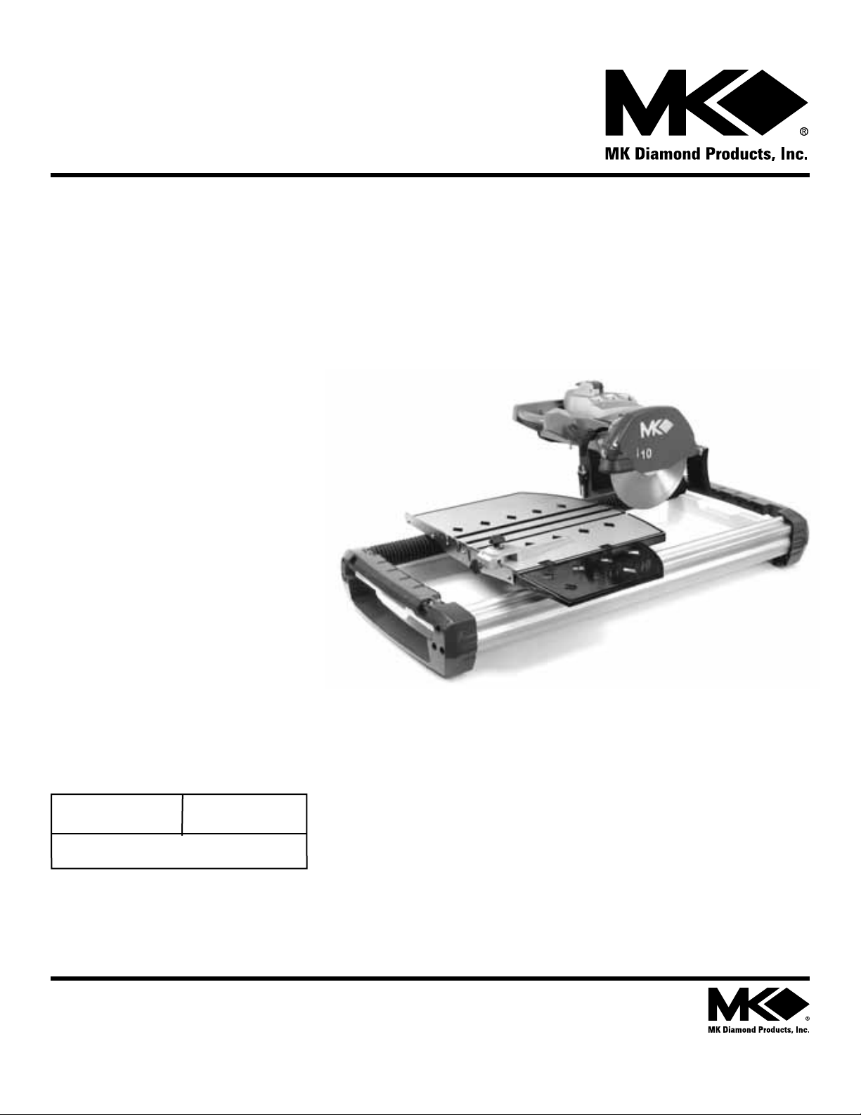
TILE SAW
OPERATION & PARTS MANUAL
Revision 104
Manual Part No. 165808
Caution: Read all safety and operating instructions before
using this equipment. This manual MUST accompany the
equipment at all times.
05.2011
MK Diamond Products, Inc.
Page 2

TX-3 INTRODUCTION
We at MK Diamond want to congratulate you on selecting the TX-3. We are certain that you will be pleased
with your purchase. MK Diamond takes pride in producing the finest products in the industry.
Operated correctly, your TX-3 should provide you with years of quality service. In order to help you, we have
included this manual. This owners manual contains information necessary to operate and maintain your TX-3
safely and correctly. Please take a few minutes to familiarize yourself with the TX-3 by reading and reviewing
this manual.
If you should have questions concerning your TX-3, please feel free to call our friendly customer service department at: 800 421-5830
Regards,
MK Diamond
22
Page 3

TX-3 TABLE OF CONTENTS
TX-3 TILE SAW
TABLE OF CONTENTS
SAFETY
Safety Message/Alert Symbols
Safety Warnings
Hazard Symbols
Rules for Safe Operation
Electric Motor Safety
Electrical Requirements and Grounding Instructions
Operation & Safety Decals
PRODUCT SPECIFICATIONS
Product Specifications
INSPECTION & START-UP
Unpacking
Setup and Adjustments, Blade Alignments and Blade Depth Adjustments
45º Miter Adjustment
Blade Vertical Adjustment
Linear Guide Bar Adjustment
Misting System Setup
PAGE NO.
3
4
5
6
7-8
9
10-11
12
13
14
15
16
17
18
19-20
OPERATION
Saw Setup
Miter Cuts
Plunge Cuts
MAINTENANCE
Blade Replacement and Motor Bushes Adjustment
Filter Replacement
Misting Pump Replacement
Wiring Diagram
GENERAL PRODUCT INFORMATION
Parts Lists
Note Page
Accessories, Ordering and Return Information
Contact Information and Limited Warranty
21
22
23
24
25-26
27
28
29-47
48
49
50
3
Page 4
TX-3 SAFETY
Safety precautions should be followed at all times when operating this equipment. Failure to read and
understand the Safety Precaution and Operating Instructions could result in injury to yourself and others.
This Operation and Parts Manual has been developed to provide complete instructions for the safe and
efficient operation of the TX-3 Tile Saw.
Before using this machine, ensure that the person operating the machine has read and understands
all instructions in this manual.
SAFETY MESSAGE / ALERT SYMBOLS
A safety message alerts you to potential hazards that could hurt you or others. Each safety message is preceded
by a safety alert symbol ( ) and one of three words: DANGER, WARNING, or CAUTION.
DANGER
You WILL be KILLED or SERIOUSLY INJURED if you do not follow directions.
WARNING
You CAN be KILLED or SERIOUSLY INJURED if you do not follow directions.
CAUTION
You CAN be INJURED if you do not follow directions. It may also be used to alert
against unsafe practices.
Each message tells you what the hazard is, what can happen, and what you can do to avoid or reduce injury.
Other important messages are preceded by the word NOTICE.
NOTICE
You can cause PROPERTY DAMAGE to your machine if you don’t follow directions.
The safety labels should be periodically inspected and cleaned by the user to maintain good legibility at a safe
viewing distance. If the label is worn, damaged or illegible, it should be replaced, contact MK Diamond or your
dealer for replacement.
4
Page 5

TX-3 SAFETY
SAFETY WARNINGS
SILICA DUST WARNING:
Grinding/cutting/drilling of masonry, concrete, metal and other materials with silica in their composition
may give off dust or mists containing crystalline silica. Silica is a basic component of sand, quartz, brick clay,
granite and numerous other minerals and rocks. Repeated and/or substantial inhalation of airborne crystalline
silica can cause serious or fatal respiratory diseases, including silicosis. In addition, California and some other
authorities have listed respirable crystalline silica as a substance known to cause cancer. When cutting such
materials, always follow respiratory precautions.
CALIFORNIA PROPOSITION 65 MESSAGE:
Some dust created by power sanding, sawing, grinding, drilling, and other construction activities contain
chemicals known (to the State of California) to cause cancer, birth defects or other reproductive harm.
Some examples of these chemicals are:
• Lead, from lead-based paints
• Crystalline silica, from bricks and cement and other masonry products
• Arsenic and chromium, from chemically treated lumber
For further information, consult the following sources:
http://www.osha.gov/SLTC/silicacrystalline/index.html
http://www.oehha.org/prop65/out_of_date/6022kLstA.html
Your risk from these exposures varies depending on how often you do this type of work. To reduce your
exposure to these chemicals, work in a well-ventilated area, and work with approved safety equipment,
such as those dust masks that are specially designed to filter out microscopic particles.
5
Page 6
TX-3 SAFETY
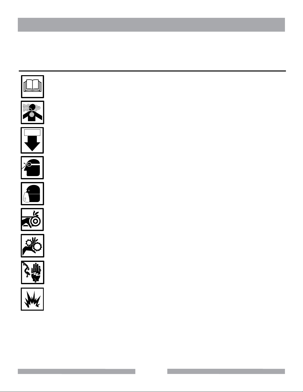
Potential hazards associated with the TX-3 Tile Saw operation will be referenced with Hazard Symbols which
appear throughout this manual, and will be referenced in conjunction with Safety Message/Alert Symbols.
HAZARD SYMBOLS
A LWAYS read this Owner’s Manual before operating the machine.
ALWAYS avoid inhalation of and skin contact with silica dust and/or mist.
ON / OFF
A LWAYS place the power ON/OFF switch in the OFF position when the TX-3 is not in use.
A LWAYS wear approved eye protection.
A LWAYS wear approved respiratory protection.
NEVER operate equipment with covers, or guards removed. Keep fingers, hands, hair and
clothing away from all moving parts to prevent injury.
ALWAYS use caution around gears. Keep fingers, hands, hair and clothing away from all moving
parts to prevent injury.
NEVER touch the power cord with wet hands or while standing in water when it is connected
to a power source.
NEVER operate the machine in an explosive atmosphere or near combustible materials.
6
Page 7
TX-3 SAFETY
RULES FOR SAFE OPERATION
DANGER
Failure to follow instructions in this manual may lead to serious injury or even death! This equipment is to
be operated by trained and qualified personnel only! This equipment is for industrial use only.
The following safety guidelines should always be used when operating the TX-3 Tile Saw.
GENERAL SAFETY
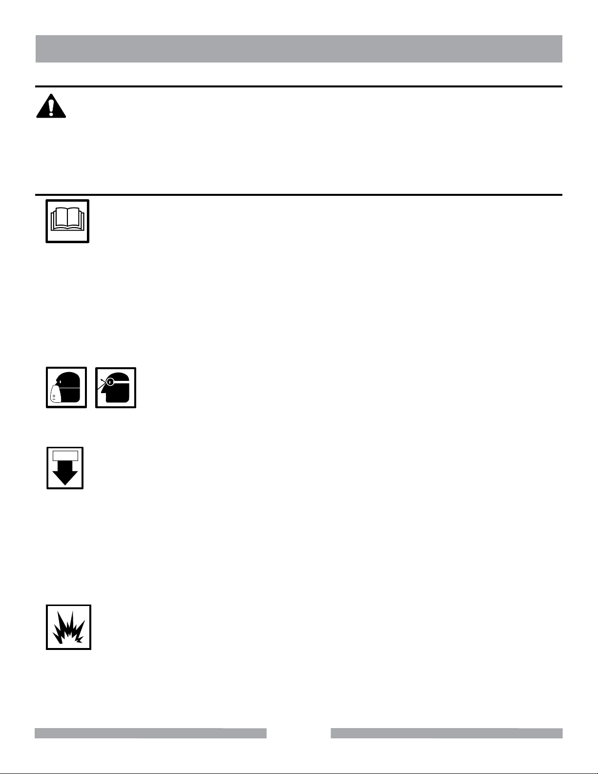
•DONOT operate or service this equipment before reading this entire manual.
This equipment should not be operated by persons under 18 years of age.
•
NEVER operate this equipment without proper protective clothing, shatterproof glasses, steeltoed boots
•
and other protective devices required by the job.
NEVER operate this equipment when not feeling well due to fatigue, illness or taking medicine.
•
NEVER operate this equipment under the influence of drugs or alcohol.
•
Whenever necessary, replace nameplate, operation and safety decals when they become difficult to read.
•
•
A LWAYS check the machine for loose bolts before starting.
•ALWAYS wear proper respiratory (mask) hearing and eye protection
equipment when operating this machine.
•
A LWAYS store equipment properly when it is not being used. Equipment should be stored in a clean, dry
location out of the reach of children.
ON / OFF
•NEVER leave the machine unattended. Turn off electric motor when unattended.
CAUTION must be observed while servicing the machine. Rotating parts can cause injury if contacted.
•
Ensure that any electrical extension cord is protected against damage. Always ensure that the electrical
•
extension cord is not trapped underneath the machine. When using an extension cord, be sure to use one
heavy enough to carry the current your product will draw. An undersized cord will cause a drop in line voltage that will result in a loss of power and overheating. The Table shown on page 9 shows the correct AWG
size to use depending on cord length and nameplate ampere rating. If in doubt, use the next heaviest gage.
The smaller the gage number, the heavier the cord.
•
DO NOT allow extension cord to come into contact with water or fluids. DO NOT spray water onto electric motor.
•NEVER operate the machine in an explosive atmosphere.
•
Before starting the machine, check that all guards are in position and correctly fitted.
•
Keep area around the machine clear of obstructions which could cause persons to fall onto moving parts.
•
A LWAYS ensure that the machine is on level ground before using.
•
DO NOT overreach. Keep proper footing and balance at all times.
7
Page 8
TX-3 SAFETY
•NEVER stand on the tool. Serious injury could occur if a power tool is tipped, or if a cutting tool is
unaintentionally contacted.
•Become familiar with the controls of the machine before operating. Know how to stop the machine quickly
in case of emergency.
•ALWAYS secure work. Clamps or a vise should be used to hold work whenever practical. Keeping your
hands free to operate a power tool is safer.
•ALWAYS disconnect AC power plug from power source before moving, cleaning or servicing the
machine.
•NEVER leave a tool running unattended. Do not leave a tool until it comes to a complete stop.
ALWAYS turn a power tool OFF when leaving the work area, or when a cut is finished.
•Make sure the OFF/ON power switch on the electric motor is always in the OFF position before
inserting the machine’s power plug into an AC receptacle.
•Operate electric motor only at the specified voltage indicated on the nameplate.
•NEVER disconnect any “emergency or safety devices”. These devices are intended for operator safety.
Disconnection of these devices can cause severe injury, bodily harm or even death! Disconnection
of any of these devices will void all warranties.
•Unauthorized equipment modifications will void all warranties. Manufacturer does not assume responsibility
for any accident due to equipment modifications.
•NEVER use accessories or attachments, which are not recommended by MK Diamond for this equipment.
Damage to the equipment and/or injury to user may result.
• Replace damaged cutting blade before operating.
• NEVER try to stop a moving blade with your hand.
WARNING
NEVER use this machine with any cutter designed for wood working.
MAINTENANCE SAFETY
•NEVER lubricate components or attempt service on a running machine.
•Keep the machinery in proper running condition.
•Before using a power tool, check for damaged parts. A guard or any other part that is damaged should be
carefully checked to determine if it would operate properly and perform its intended function. Always
check moving parts for proper alignment or binding. Check for broken parts and mountings and all other
conditions that may affect the operation of the power tool. A guard, or any damaged part, should be
properly repaired or replaced.
SAW SAFETY
WARNING
•Wear eye protection.
•Disconnect saw before servicing, when changing cutting blades and cleaning.
•Use tool only with smooth edge cutting blades free of openings and grooves.
•Replace damaged cutting blade before operation.
•Remove adjusting keys and wrenches.
8
Page 9
TX-3 SAFETY
ELECTRIC MOTOR SAFETY
For maintenance care and operation of the electric motor, refer to your electric motor instruction booklet
furnished with the electric motor.
Protect the electric motor from dust as much as possible and keep ventilating openings clean.
CAUTION
DO NOT spray water on the electric motor. Do not touch the plug with wet hands. To reduce the risk of
•
electrocution, keep all connections dry and off the ground.
•
DO NOT operate electric motor in an explosive environment.
WARNING
Use only extensions cords that are intended for outdoor use. These extension cords are identified by a
marking “Acceptable for use with outdoor appliances; store indoors while not in use.” Use only extension
cords having an electrical rating not less than the rating of the product. Do not use damaged extension cords.
Examine extension cords before using and replace if damaged. Do not abuse extension cords and do not yank
on any cord to disconnect. Always disconnect the extension cord from the receptacle before disconnecting
the product from the extension cord.
Electric Motor Connection
A LWAYS make certain that the power source required for the electric motor is correct and always use the
correct NEMA configuration plug. Motors can burn out when the line voltage falls 10% below the voltage rating of the motor. Failure to use proper voltage will cause the motor to overheat. Make certain that the correct
size grounded (3-wires) extension cord is used. See the table below.
To choose the proper extension cord:
NOTICE
•
Locate the length of extension cord needed in
table to the right.
•
Once the proper length is found, move down the
column to obtain the correct AWG size required
for that length of extension cord.
Most Motor Problems are caused by improper
voltage and extension cords. Cord should be
one-piece and short as possible. Cord
selection should match the following table.
1-2 H.P.
115v 230v
25’
100’
50’
150’
75’
250’
Max. Cord Length
Max. Cord Length
Max. Cord Length
Fig. 1 Extension Cord Table
No. 12 Wire
No. 10 Wire
No. 8 Wire
WARNING
Use of undersize extension cords result in low voltage to the motor that can result in motor burnout and premature failure. MK Diamond warns that equipment returned to us showing signs of being run in a low voltage
condition, through the use of undersized extension cords will be repaired or replaced totally at the customers
expense. There will be no warranty claim.
9
Page 10
TX-3 SAFETY
ELECTRICAL REQUIREMENTS AND GROUNDING INSTRUCTIONS
In order to prevent potential electrical shock and injury, the following electrical safety precautions and symbols
should be followed at all times!
WARNING
In case of a malfunction or breakdown, grounding provides a path of least resistance for electric current to
reduce the risk of electric shock. This tool is equipped with an electric cord having an equipment-grounding
conductor and a grounding plug. The plug must be plugged into a matching outlet that is properly installed and
grounded in accordance with all local codes and ordinances.
•
Do not modify the plug provided – if it will not fit the outlet; have the proper outlet installed by a qualified
electrician.
•
Improper connections of the equipment-grounding conductor can result in a risk of electric shock. The
equipment-grounding conductor is the insulated conductor that has an outer surface that is green, with or
without yellow stripes. If repair or replacement of the electric cord or plug is necessary, do not connect
the equipment-grounding conductor to a live terminal.
•
Check with a qualified electrician or service personnel if the grounding instructions are not completely
understood, or if in doubt as to whether the tool is properly grounded.
•
Use only 3-wire extension cords that have 3-prong grounding plugs and 3-pole receptacles that accept the
tool’s plug.
•
Repair or replace a damaged or worn cord immediately.
WARNING
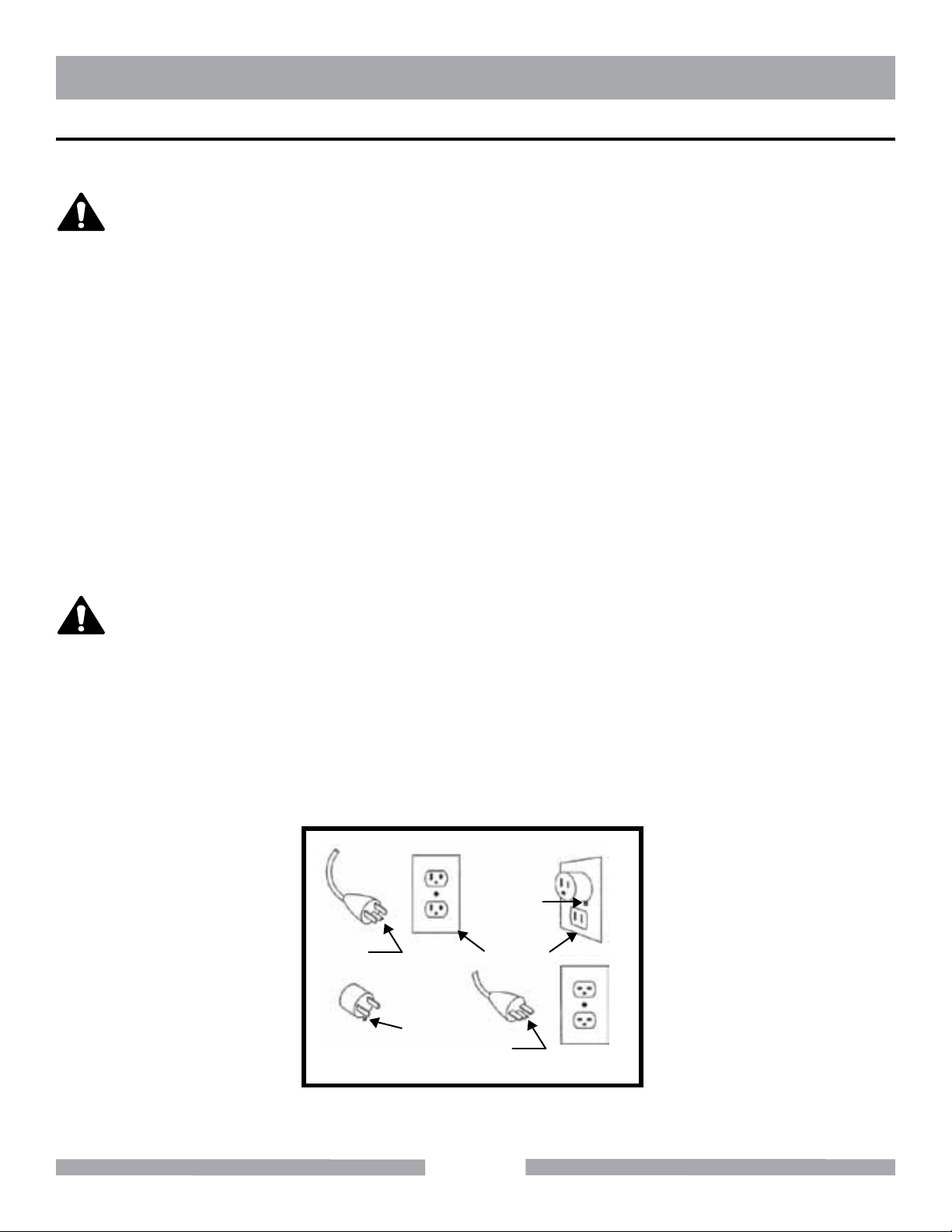
This tool is intended for use on a circuit that has an outlet that looks like the one shown in Sketch A of
Figure 1. The tool has a grounding plug that looks like the plug illustrated in Sketch A of Figure 1. A temporary
adapter, which looks like the adapter illustrated in sketches B and C, may be used to connect this plug to a
2-pole receptacle as shown in Sketch B, if a properly grounded outlet is not available. The temporary adapter
should be used only until a properly grounded outlet can be installed by a qualified electrician. The greencolored rigid ear, lug, and the like, extending from the adapter, must be connected to a permanent ground such
as a properly grounded outlet box.
NOTE: Use of a temporary adapter is not permitted in Canada.
Metal Screw
Grounding
Pin
(A)
ADAPTER
Grounding
Means
(C)
Cover of
Grounded
Outlet Box
Grounding
Pin
(B)
(D)
Fig. 1 Circuit and Adapter Information
10
Page 11
Surface
TX-3 SAFETY
WARNING
To reduce the risk of electrocution, keep all connections dry and off the ground.
A Ground Fault Circuit Interrupter (GFCI) should be provided on the circuit(s) or outlet(s) to be used for this
machine. Receptacles are available having built-in GFCI protections and may be used for this measure of safety.
When using an extension cord, the GFCI should be installed closest to the power source, followed by the
extension cord and lastly, the machine.
WARNING
The pump requires a GFCI. To reduce risk of electric shock when operating the machine with the pump
plugged into the 3-pole receptacle on the motor, connect the saw to a GFCI outlet. See the pump manual and
informational tags enclosed separately for all pump information.
WARNING
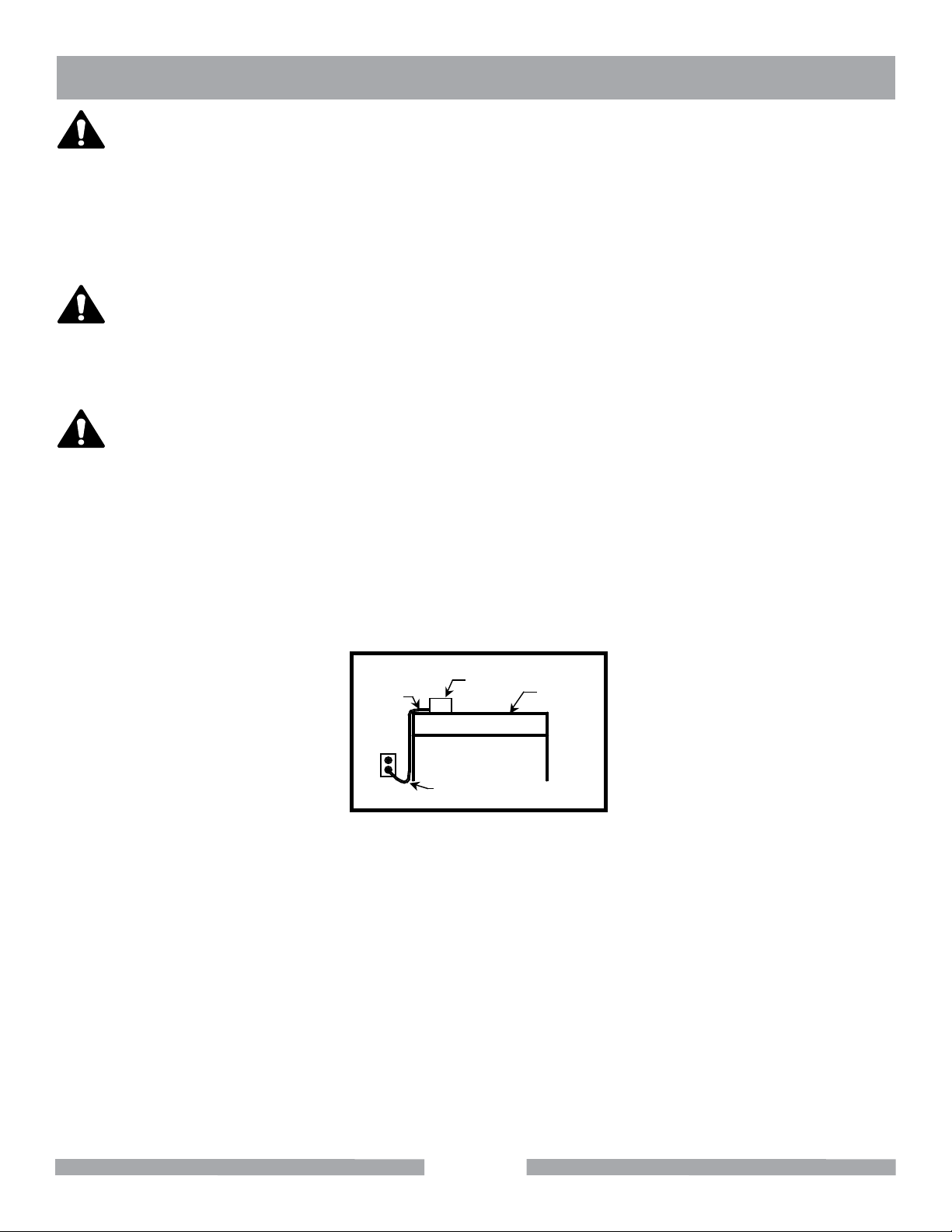
To avoid the possibility of the appliance plug or receptacle getting wet, position the machine to one side of a
wall mounted receptacle. This will prevent water from dripping onto the receptacle or plug. A “drip loop,” shown
in Figure 2, should be arranged by the user to properly position the power cord relative to the power source.
The “drip loop” is that part of the cord below the level of the receptacle, or the connector, if an extension
cord is used. This method of positioning the cord prevents the travel of water along the power cord and
coming in contact with the receptacle.
If the plug or receptacle gets wet, DO NOT unplug the cord. Disconnect the fuse or circuit breaker that
supplies power to the tool. Then unplug and examine for presence of water in the receptacle.
Power
Cord
Fig. 2 Drip Loop Information
Power
Tool
Drip Loop
Supporting
11
Page 12
TX-3 SAFETY
OPERATION & SAFETY DECALS
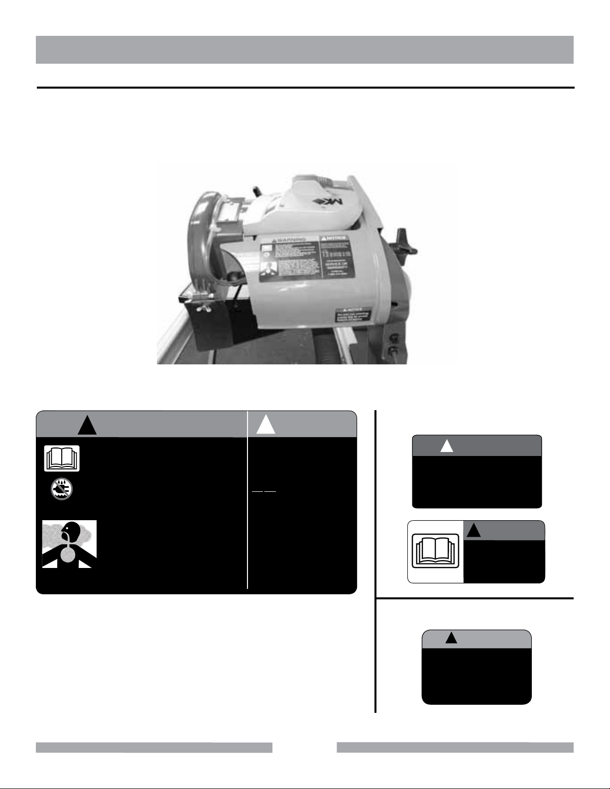
Safety labels are located on the back of the motor assembly (figure 3). The labels contain important safety information. Please read the information contained on each safety label. These labels are considered a permanent
part of your saw. Should any of these decals become unreadable, replacements can be obtained by calling
(800) 262-1575.
Fig. 3 TX-3 Safety Decal Location
!
WARNING
• For Your Own Safety Read Instruction Manual
Before Operating Saw.
• Wear Eye Protection.
• Disconnect Saw Before Servicing, when Changing
Cutting Wheels and Cleaning.
• Use Tool Only with Smooth Edge Cutting Wheels
Free of Openings and Grooves.
• Replace Damaged Cutting Wheel Before Operating.
• Do Not Fill Water Bath Above Water Fill Line.
• See Manual for Pump Replacement.
Grinding/cutting/drilling of masonry, concrete,
metal and other materials with silica in their
composition may give off dust or mists containing crystalline silica. Silica is a basic component
of sand, quartz, brick clay, granite and numerous
other minerals and rocks. Repeated and/or substantial inhalation of airborne crystalline silica can
cause serious or fatal respiratory diseases, including silicosis. In addition, California and some
other authorities have listed respirable crystalline
silica as a substance known to cause cancer.
NOTICE
!
Most Motor Problems are caused by improper
voltage and extension cords. Cord should be
one-piece and short as possible. Cord
selection should match the following table.
1-2 H.P.
115v 230v
25’
50’
75’
Max. Cord Length
100’
Max. Cord Length
150’
Max. Cord Length
250’
FOR INFORMATION ON
No. 12 Wire
No. 10 Wire
No. 8 Wire
SERVICE OR
WARRANTY
PLEASE CALL
1-800-474-5594
Fig. 4 TX-3 Safety Decal Sheet, Part #166787
Misting Version Only, Part #164800
!
NOTICE
Do not run misting
pump dry to avoid
failure of pump
!
WARNING
DO NOT operate
this equipment
before reading the
owners’ manual!
Flood Version Only, Part #166634
CAUTION
!
• Receptacle is for water
pump only.
This saw is to be used
•
with a Ground Fault
Circuit Interrupter.
12
Page 13

TX-3 PRODUCT SPECIFICATIONS
PRODUCT SPECIFICATIONS
The TX-3 is a versatile tile saw. Operated and used according to this manual, the TX-3 will provide years of
dependable service.
GENERAL DESCRIPTION
The TX-3 is engineered as a 10” Tile Saw with a misting or flood system.
PART # DESCRIPTION
164800 With Misting System
166634 With Flood System
MOTOR AND WEIGHT SPECIFICATIONS
Motor and Weight specifications for the TX-3 are listed in the Table below.
VOLTAGE 120V
AMPERAGE 15
FREQUENCY 50-60 Hz
RPM 3,500 RPM
WEIGHT 85 lbs. (39 kg)
BLADE CAPACITY
The TX-3 uses a 10-inch diameter segmented MK Diamond blade with a .06-inch cutting width and 1-inch
arbor.
TILE TYPES
The TX-3 can cut a variety of tile types including stone, masonry, and lapidary products.
NOTE
The TX-3 is not designed to cut plastic or metals.
SPRING ASSISTED CUTTING HEAD
The TX-3 is designed with a spring assisted Cutting Head to allow for plunge cutting. The Cutting Head can be
locked in any down position when using with smaller blade or profile wheel.
REMOVABLE MOTOR AIR FILTER
The TX-3 is designed with an easy clean motor air filter to extend the life of the motor.
REPLACEABLE MOTOR BRUSHES
The TX-3 is designed with replaceable motor brushes to extend operating life.
13
Page 14
TX-3 INSPECTION & STARTUP
UNPACKING
Your TX-3 has been shipped from the factory thoroughly inspected. Only minimal assembly is required.
CONTENTS
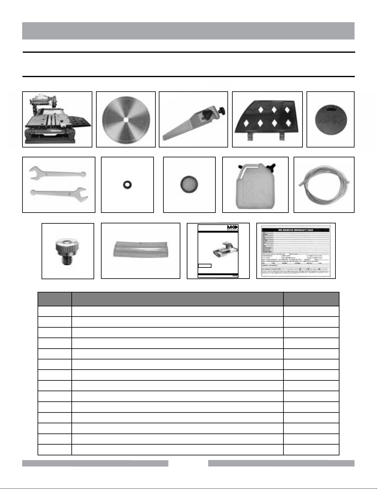
If not already done, remove the TX-3 from the carton and place it on a flat surface. Check contents with list below:
1 2 3 4 5
6 7 8 9 10
www.mkdiamond.com
OPERATION & PARTS MANUAL
Caution: Read all safety and operating
instructions before
using this equipment. This manual MUST accompany
the equipment at all times.
11 12 13
TILE SAW
MK Diamond Products, Inc.
TX-3
14
ITEM NO. DESCRIPTION QUANTITY
1 TX-3 1
2 10” WET CUTTING TILE BLADE 1
3 ADJUSTABLE CUTTING GUIDE 1
4 SIDE CUTTING TABLE 1
5 DRAIN PLUG 1
6 WRENCHES 2
7 GROMMET 1
8 FILTER 1
9 WATER TANK 1
10 PLASTIC TUBING 1
11 NOZZLE, 1.0mm 2
12 ADAPTER 1
13 OPERATION & PARTS MANUAL 1
14 WARRANTY CARD 1
14
Page 15
TX-3 INSPECTION & START-UP
SETUP AND ADJUSTMENTS
WARNING
A LWAYS disconnect unit from power supply when performing changes or adjustments.
You will need the following tools:
1.
Combination Square
2.
Hex Nut Wrench Set
3.
Phillips Screwdriver
BLADE ALIGNMENTS
The TX-3 has been factory aligned. If any adjustment should occur, refer to steps below for specific adjustments.
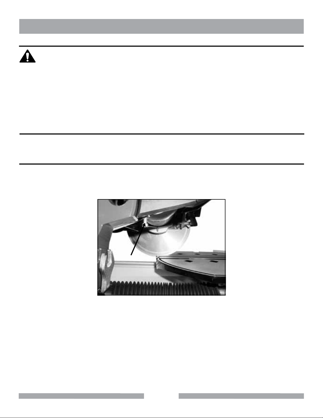
BLADE DEPTH ADJUSTMENT
Loosen Hex Nut (A) on blade depth adjustment screw.
1.
Set Blade (B) approximately 3/16” below the table surface by turning adjustment screw. Retighten Hex Nut
2.
to secure Screw after desired depth is achieved.
B
A
15
Page 16

TX-3 INSPECTION & START-UP
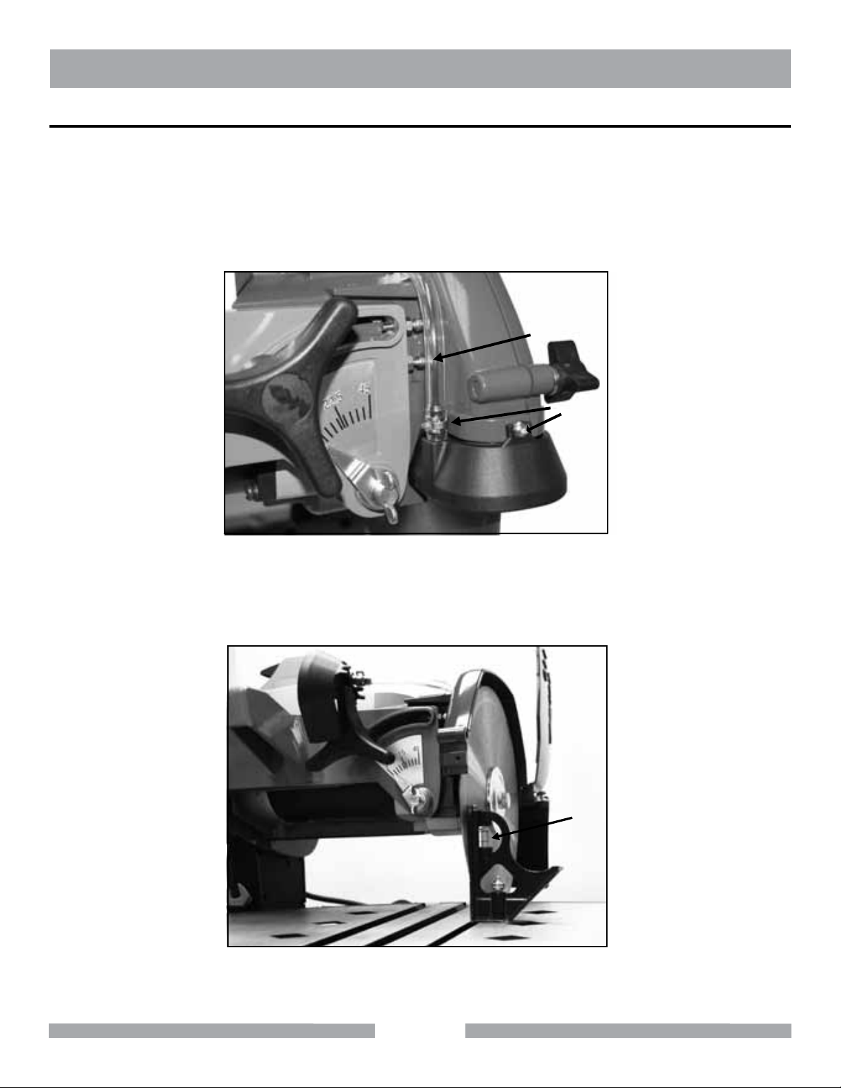
45º MITER ADJUSTMENT
A Combination Square (H) is needed for 45º adjustment.
Loosen Miter Adjustment Knob (C) and tilt Cutting Head.
1.
Remove Outer Blade Guard by turning Outer Blade Guard Release Knob (D) and pushing Outer Blade
2.
Guard back.
Remove Misting Module (E) by loosening the two Misting Module Screws (F).
3.
Loosen the Hex Nut on the 45º Adjustment Screw (G).
4.
G
D
F
C
E
5.
Turn 45º Adjustment Screw (G) and set vertical position of Roller Wheel Bracket (I) until Blade is parallel
with 45º level on the Combination Square (H).
6.
Tighten Hex Nut on the 45º Adjustment Screw (G) to secure Screw and Roller Wheel Bracket (I) in place.
Fig. 16 Remove material slide
H
16
I
Page 17
TX-3 INSPECTION & START-UP
BLADE VERTICAL ADJUSTMENT
A combination square (H) is needed for 45º adjustment.
Remove Outer Blade Guard by turning Outer Blade Guard Release Knob (J) and pushing Outer Blade
1.
Guard back.
2.
Remove Misting Module (M) by loosening the two Misting Module Screws (K).
3.
Loosen the Hex Nut on the Vertical Adjustment Screw (L).
G
L
J
D
K
F
M
C
4.
Turning Vertical Adjustment Screw (L) until Blade is perpendicular with the top surface of the table by using
a square (H) as shown in figure below.
5.
Tighten Hex Nut to secure Vertical Adjustment Screw (L) in place.
17
H
Page 18
TX-3 INSPECTION & START-UP
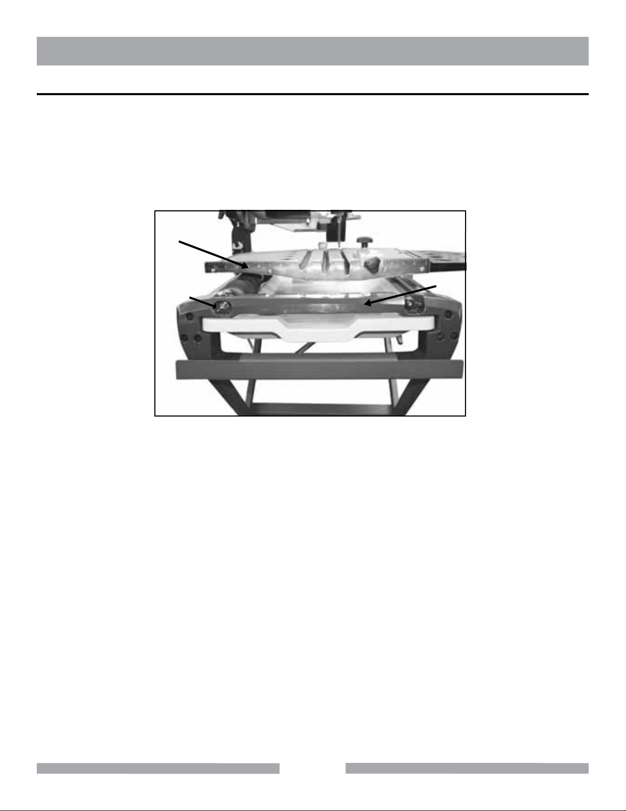
LINEAR GUIDE BAR ADJUSTMENT
A combination square is needed for 45º adjustment. This adjustment is to ensure consistency of material cutting
width.
1.
Loosen Guide Bar Adjustment Screws (N) on front and rear End Caps (O).
2.
Tap Guide Bar lightly until Table Fence (P) is perpendicular with the blade by using a combination square.
3.
Tighten up Screws and re-check that the Blade is square with the Table Fence (P).
P
N
O
18
Page 19
TX-3 INSPECTION & START-UP
MISTING SYSTEM SETUP
WARNING
ALWAYS disconnect unit from power supply when performing changes or adjustments.
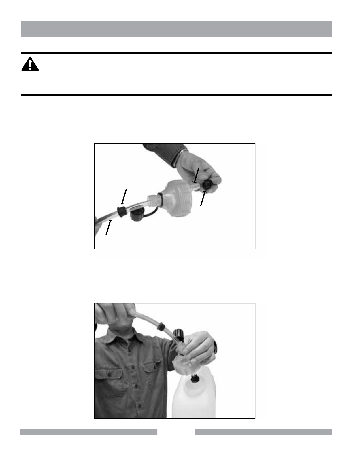
STEP 1 - SETTING UP THE WATER TANK
1.
Install Grommet (Q) through one end of the Hose (R).
2.
Feed the Hose through the Main Cap (U).
3.
Insert Hose 1” minimum into Tube Adapter (S).
4.
Insert Tube Adapter (S) into Filter (T).
S
Q
C
R
5.
Press Grommet (Q) into the Main Cap (U).
6.
Fill Water Tank up with clean water.
7.
Screw Main Cap (U) onto Water Tank.
8.
Ensure Filter sits on the bottom of the Tank at all times.
T
U
19
Page 20
TX-3 INSPECTION & START-UP
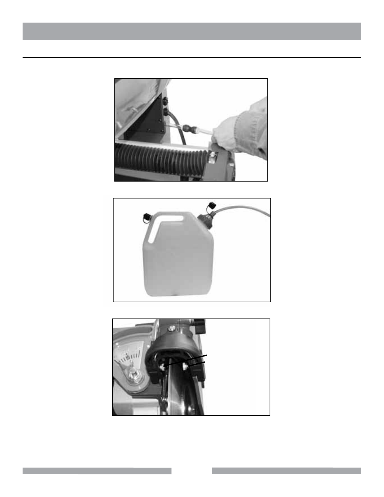
STEP 2 - ATTACHING WATER TANK TO SAW
Insert other end of the Hose (W) into Coupling (V) attaching to the Saw.
1.
V
W
Open Vent Cap (X) on Water Tank before operating the equipment.
2.
X
3.
Turn on equipment to make sure fine mists are being delivered through both Misting Nozzles (Y).
Y
Note: Nozzles may be changed to provide additional water flow. The TX3 is shipped with 0.3mm misting nozzles installed on the
saw, with an additional pair of 1.0mm nozzles included (see contents table on page 14). If you are in need of more water flow
to control dust, the 1.0mm nozzles may be substituted. To remove a nozzle, simply unscrew it counterclockwise. If even more
water is needed, the nozzles can be removed completely, thus making a “flood” type saw. If running the saw without nozzles, the
water supply will diminish quickly. Keep an eye on the water level, so as not to run the pump when dry. Running the pump dry
will cause damage.
20
Page 21
TX-3 OPERATION
WARNING
ALWAYS disconnect unit from power supply when performing changes or adjustments.
CAUTION
ALWAYS ensure there is a sufficient amount of clean water in the Water Tank and the Filter is submerged in
the water to ensure proper performance of the misting system and to prevent Pump damage.
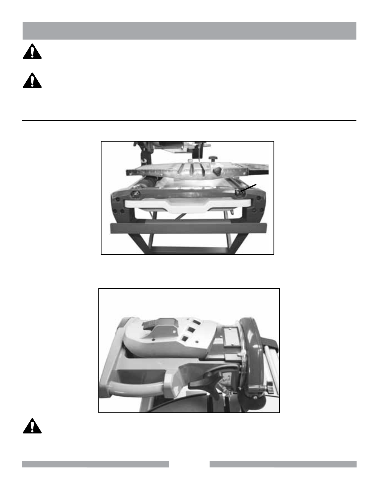
SAW SETUP
1.
Rotate Table Lock (A) clockwise to release Table (B) from lock position.
B
A
C
2.
Turn on equipment with the Toggle Switch (D) to make sure fine mists are delivered through Misting
Nozzles.
D
NOTICE
Move Table (B) all the way to the Front End Cap (C), hold Table (B) in place and rotate Table Lock (A)
counterclockwise to lock Table (B) in place for transportation.
21
Page 22
TX-3 OPERATION
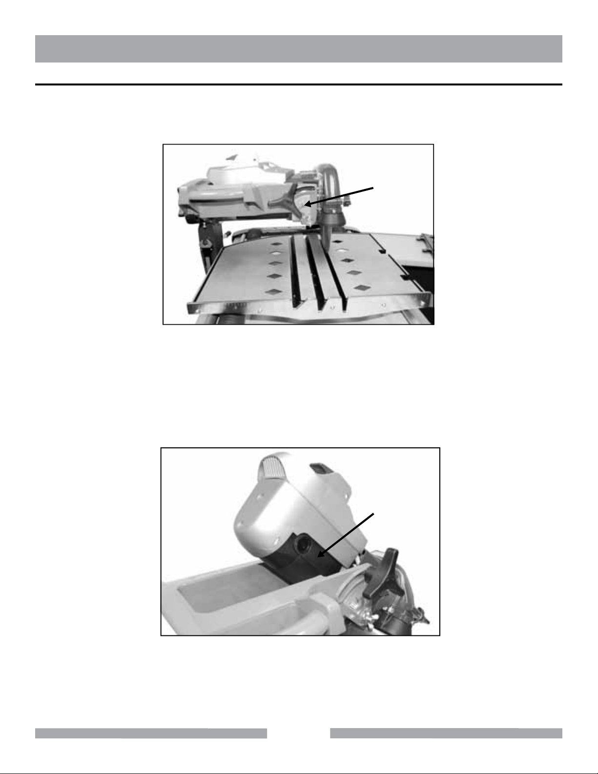
MITER CUTS
1.
The Table (F) has 45º (G), 22.5º (H) and 90º (I) clearance slots built-in. 90º and 45º are pre-set at the factory.
22.5º miter can be obtained by aligning the Pointer to 22.5 mark on the Miter Index (E). All other angular
cuts can be obtained by raising the work up. Make sure the Blade will clear the Table before operations.
E
F
H I
G
2.
Move the Table (F) toward the front of the Saw so that the Blade does not interfere with the Table when
setting up the Cutting Head.
3.
To perform miter cuts, loosen the Miter Adjustment Knob (J) and lift Air Flow Module (K) with the Air Flow
Module Handle (M) located in the rear of the Upper Air Flow Module (K).
4.
Tilt Motor Assembly (L) to desired degree using the Miter Index (E).
5.
Tighten Miter Adjustment Knob (J) to hold Motor Assembly (L) in position.
M
K
L
J
22
Page 23
TX-3 OPERATION
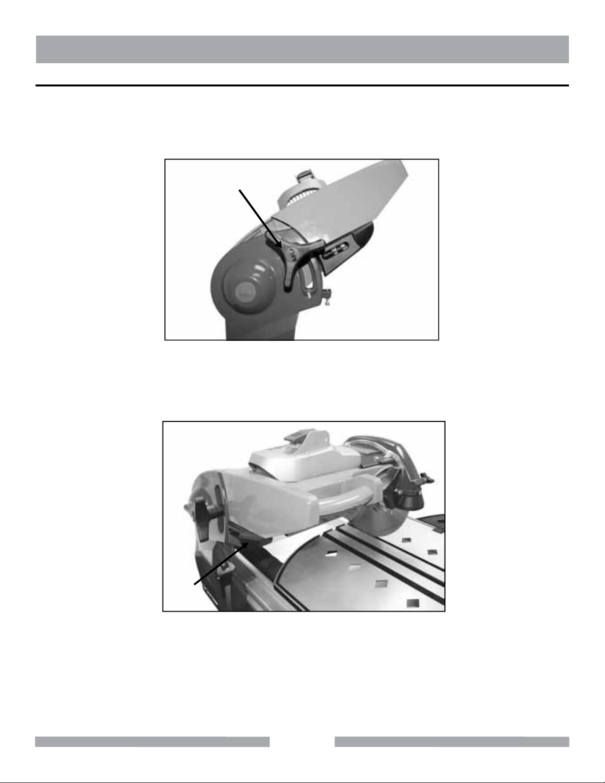
PLUNGE CUTS
1.
Loosen Cutting Head Knob (O) so that the Cutting Head Assembly (N) will swing upward.
2.
Shift Plunge Lock Lever (Q) forward.
3.
Push Cutting Head Handle (P) downward to perform plunge cuts.
O
N
Shift Plunge Lock Lever (Q) back while Cutting Head Assembly (N) is at uppermost position.
4.
Bring Cutting Head Assembly (N) down to stop on the Plunge Lock Lever (Q).
5.
Tighten Cutting Head Knob (O) for normal operations.
6.
P
Q
23
Page 24
TX-3 MAINTENANCE
WARNING
ALWAYS disconnect unit from power supply when performing changes or adjustments.
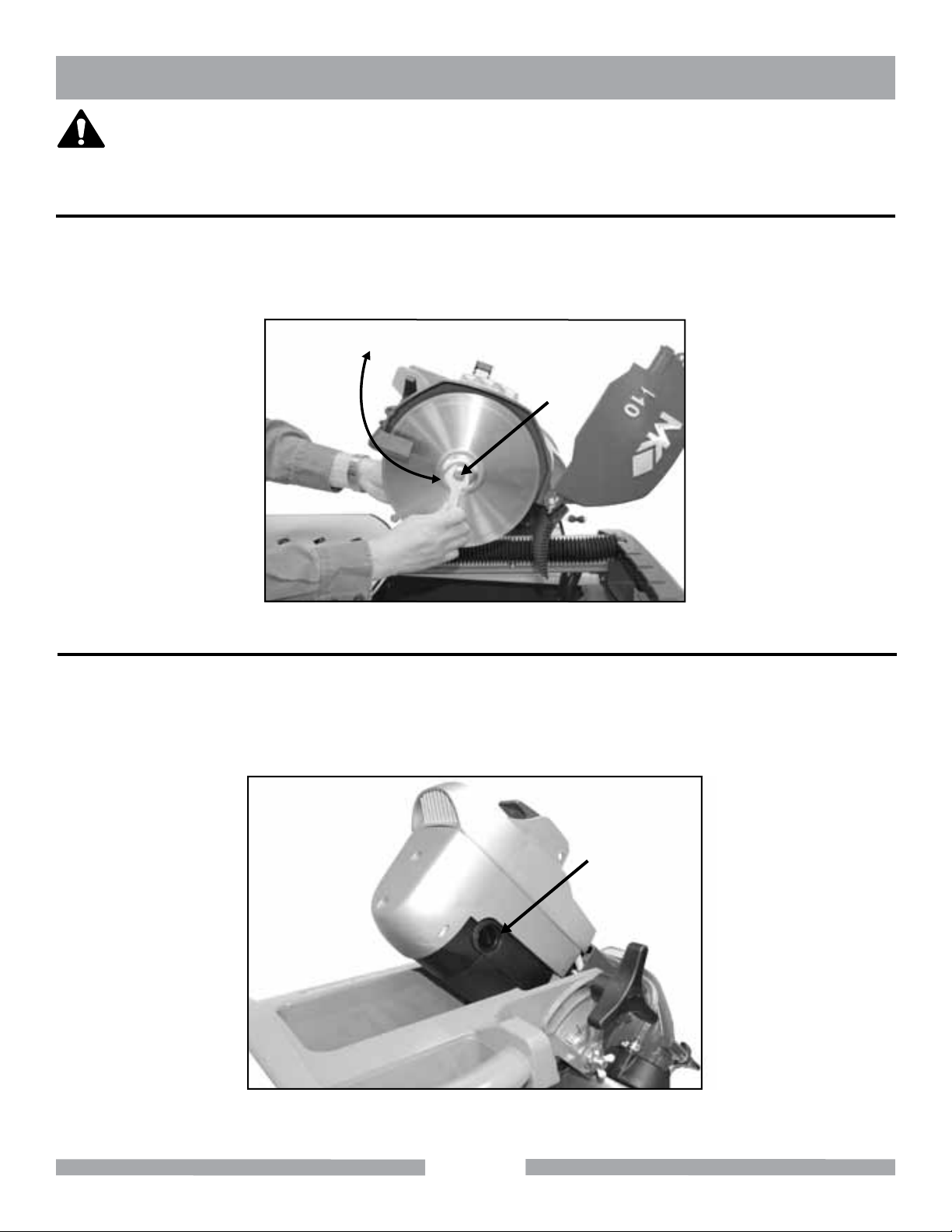
BLADE REPLACEMENT
1.
Hold Wrench over two flats on Motor Shaft on the inner side of the Blade.
2.
Rotate Wrench (B) on the outer side of Blade counterclockwise to loosen and clockwise to tighten the
Blade Screw (A).
B
A
MOTOR BRUSHES REPLACEMENT
Tilt Motor Assembly (Q) at 45º and tighten Miter Adjustment Knob (R) to hold Motor Assembly in place.
1.
Remove Brush Caps (S) on both sides of Motor.
2.
Replace Brushes and reinstall Brush Caps (S).
3.
Q
S
R
24
Page 25
TX-3 MAINTENANCE
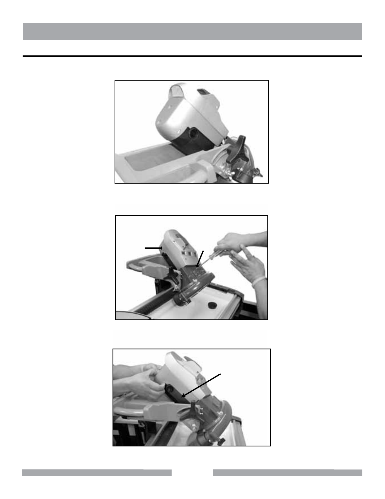
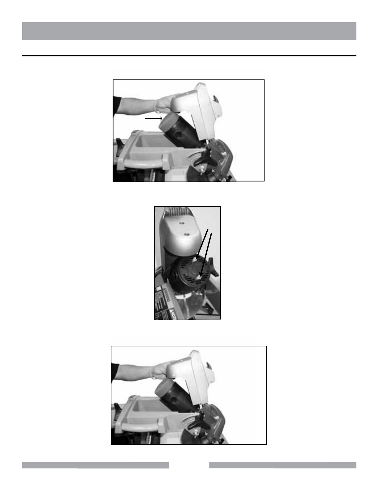
FILTER REPLACEMENT
1.
Tilt Motor Assembly (C) at 45º and tighten Miter Adjustment Knob (D) to hold Motor Assembly (C) in place.
C
D
2.
Remove one screw, which secures Lower Air Flow Module (E) through Inner Blade Guard (F) with a Phillips
screwdriver.
E
3.
Pull Lower Air Flow Module (H) backward to separate Upper and Lower Air Flow Module from Motor (I).
G
F
I
H
Y
25
Page 26
TX-3 MAINTENANCE
FILTER REPLACEMENT CONTINUED
4.
Lift Air Flow Module (K) up to remove Filter (J). Place a clean Filter onto Spacers (L) through holes in the Filter.
K
J
5.
Move Air Flow Module (K) over the Filter.
L
6.
Align holes in Lower Air Flow Module with Spacers (L). Push Air Flow Module (K) back onto Spacers (L).
K
26
Page 27
TX-3 MAINTENANCE
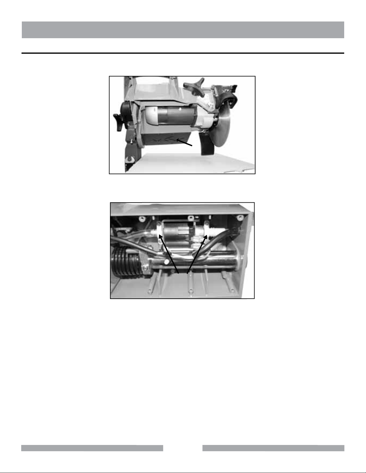
MISTING PUMP REPLACEMENT
Remove Pump Cover (M) from underside of Cutting Head (N) by loosening screws with a Phillips screwdriver.
1.
N
M
2.
Disconnect Terminals to Pump (P) and remove Clamps (O). Replace Pump (P) and reinstall Clamps (O).
P
O
27
Page 28
TX-3 MAINTENANCE
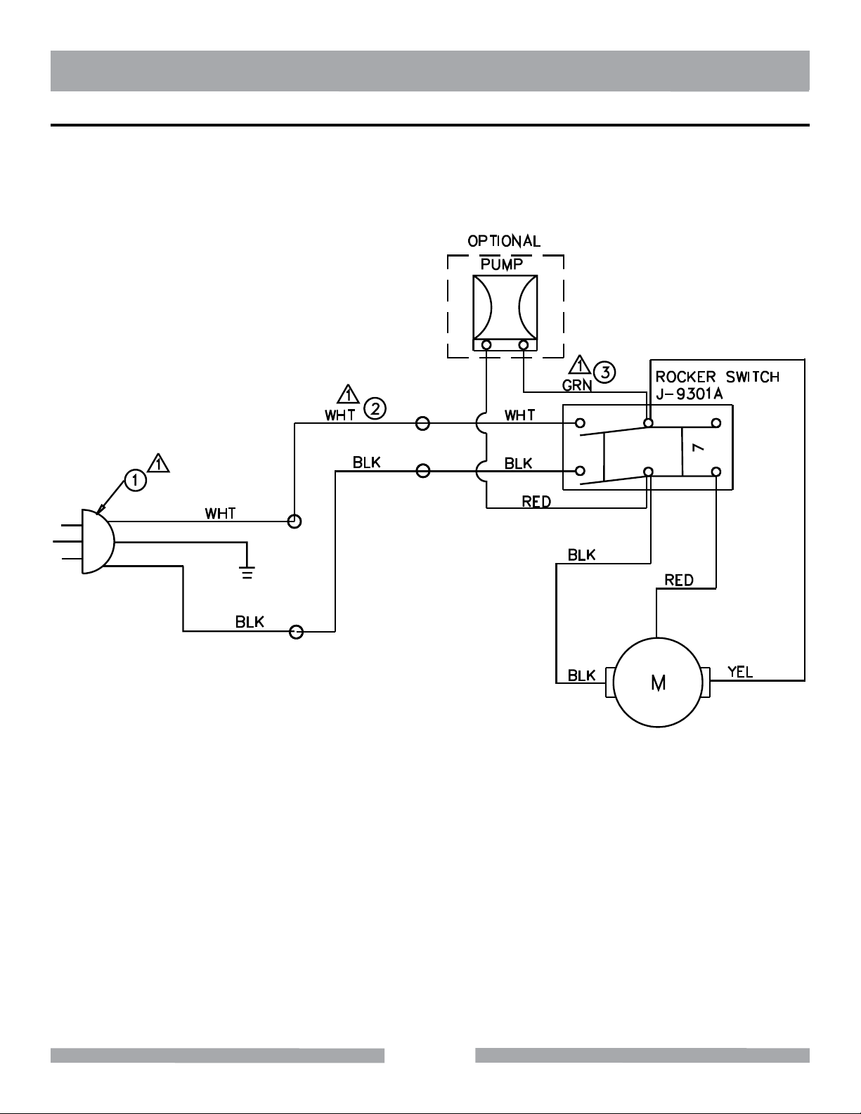
WIRING DIAGRAM
28
Page 29
TX-3 GENERAL PRODUCT INFORMATION
26
6
32
391740
27
31
38
30
29
7
8
33
2
13
19
21
20
18
371114
41
35
16
15
12
9 34
3
4
10
5
22 23
25
24
1
28
8
7
6
5
4
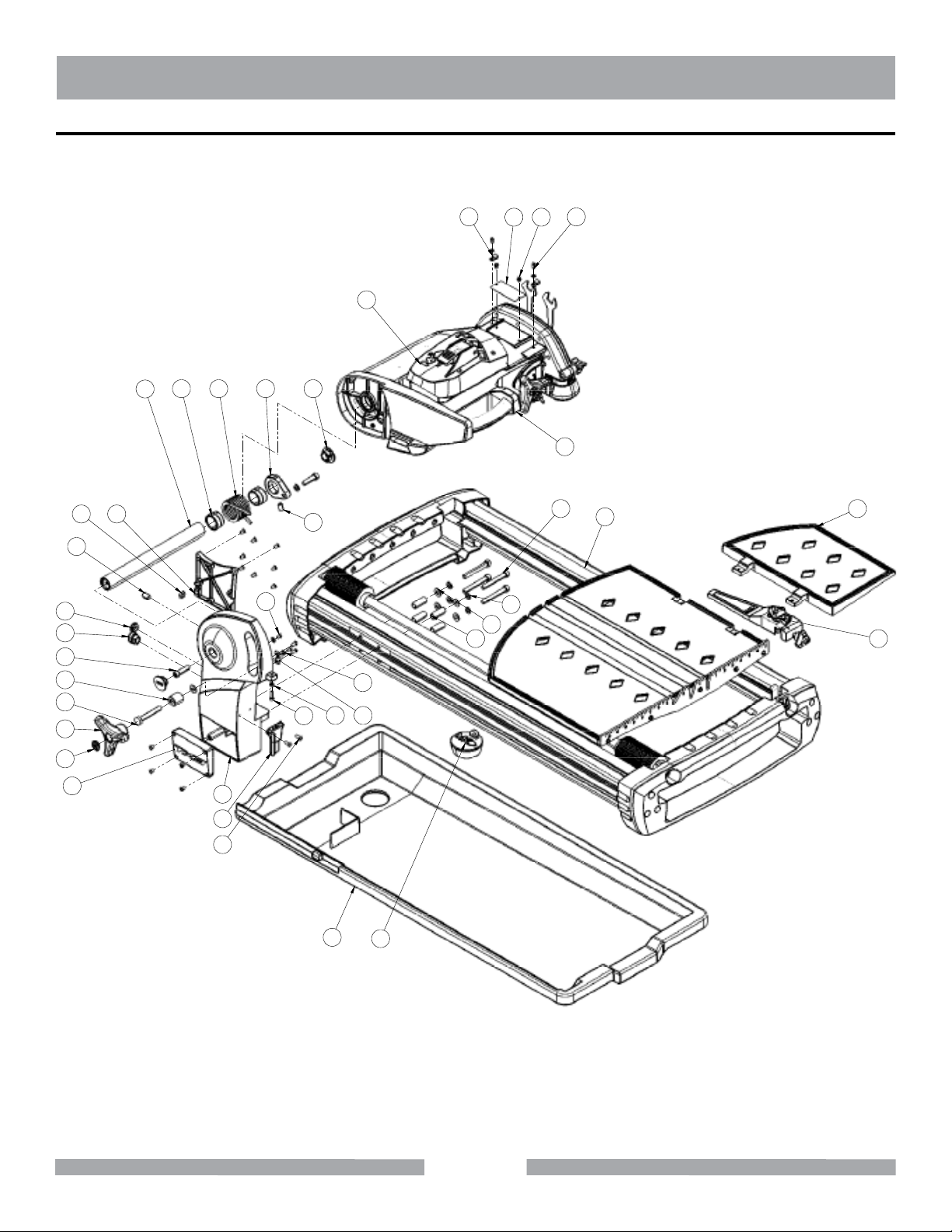
PARTS LIST - ASSY, FINAL - P/N 164800
29
Page 30
TX-3 GENERAL PRODUCT INFORMATION
PARTS LIST - ASSY, FINAL - P/N 164800
ITEM
NO.
1 ASSY, LOWER FRAME 165294 1
2 POST 164843 1
3 SPACER, POST MOUNTING 164839 4
4 WASHER, FLAT, M8 164855 5
5 WASHER, SPLIT LOCK, M8 164860 5
6 SCREW, SOCKET HD CAP, M8 X 70 MM 165301 4
7 HOLDER, WRENCH 164669 1
8 SCREW, PAN HD PHIL, M4 X 12 MM 164778 4
9 O-RING, BUNA-N, .500 X .094 165028 1
10 SHAFT, PIVOT 166686 1
11 SCREW, SOCKET HD CAP, M5 X 35 MM 165311 2
12 SCREW, SOCKET HD SET, M10 X 6 MM 166680 1
13 SCREW, SOCKET HD CAP, M5 X 18 MM 166675 1
14 CLAMP, CABLE 164759 1
15 CAP, POWER CORD 166679 1
16 BUSHING, STRAIN RELIEF 164725 1
17 ASSY, CUTTING HEAD 164850 1
18 SPACER, POST KNOB 166657 1
19 KNOB, TRI 166312 1
20 SCREW, HEX HD CAP, M8 X 65 MM 165318 1
21 CAP, TRI KNOB 166311 1
22 SPACER, SPRING 166684 2
23 SPRING, TORSION 164770 1
24 RETAINER, SPRING 164794 1
25 SCREW, SOCKET HD SET, M8 X 16 MM 166677 1
26 COVER, CUTTING HD 164847 1
27 SCREW, PAN HD PHILIP, M4 X 10 MM 164777 10
28 CAP, MK LOGO 166656 2
29 PAN, WATER 165303 1
30 PLUG, DRAIN 159858 1
31 ASSY, SIDE TABLE 165317 1
32 CLAMP, TUBE 164698 2
33 COVER, OUTER POST 164766 1
34 COVER, INNER POST 164771 1
35 SCREW, PAN HD PHIL, M4 X 8 MM 164776 14
36 WASHER, FLAT, M4 164795 2
37 NUT, HEX, M5 157405 1
38 ASSY, RIP GUIDE 165356 1
39 SERIAL TAG 157500-TX3 1
40 SCREW, QUICK DRIVE, #8 X 1/4 162850 2
41 WASHER, TOOTH LOCK EXT, M4 165352 2
DESCRIPTION
PART OR
IDENTIFYING NO.
OT Y.
REQ.
30
Page 31
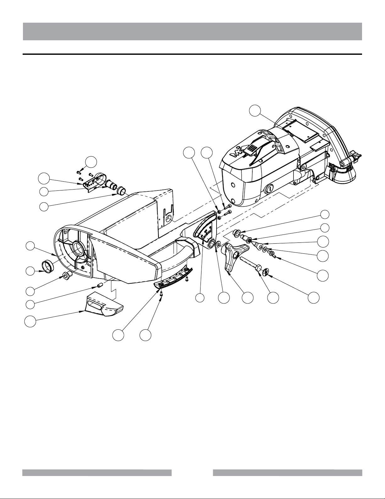
TX-3 GENERAL PRODUCT INFORMATION
PARTS LIST - ASSY, CUTTING HEAD - P/N 164850
21
12
02
11
01
9
8
6
7
1
31
41
3
51
2
5
22
42
32
52
4
91
81
11
31
Page 32
TX-3 GENERAL PRODUCT INFORMATION
PARTS LIST - ASSY, CUTTING HEAD - P/N 164850
ITEM
NO.
1 CUTTING HEAD 164841 1
2 BUSHING, THDED FLANGE 164844 1
3 BUSHING, PIVOT SHAFT 166668 2
4 PLUNGER, BALL, M8 X 15 MM 166669 1
5 INDEX, MITER 165310 1
6 BUSHING, MITERING, LEFT 166659 1
7 STUD, PIVOT 165308 1
8 BUSHING, MITERING, RIGHT 166660 3
9 BUSHING, WIRE ROUTING 164825 1
10 COVER, WIRE 164786 1
11 SCREW, PAN HS PHILIP, M4 X 10 MM 164777 9
12 ASSY, MOTOR 165029 1
13 POINTER 164828 1
14 WASHER, FLAT, 16 X 6.5 X 1 MM 166681 1
15 SCREW, WING, M6 X 12 MM 165323 1
16 PUMP 164693 1
DESCRIPTION
PART OR
IDENTIFYING NO.
OT Y.
REQ.
17 CLAMP, PUMP 165027 2
18 COVER, HANDLE 166670 1
19 STOP, BLADE DEPTH 165014 1
20 NUT, HEX, M5 157405 2
21 SCREW, SOCKET HD CAP, M5 X 18 MM 166675 2
22 WASHER, FLAT, M10 160203 2
23 SCREW, HEX HD CAP, M8 X 65 MM 165318 1
24 KNOB, TRI 166312 1
25 CAP, TRI KNOB 166311 1
32
Page 33
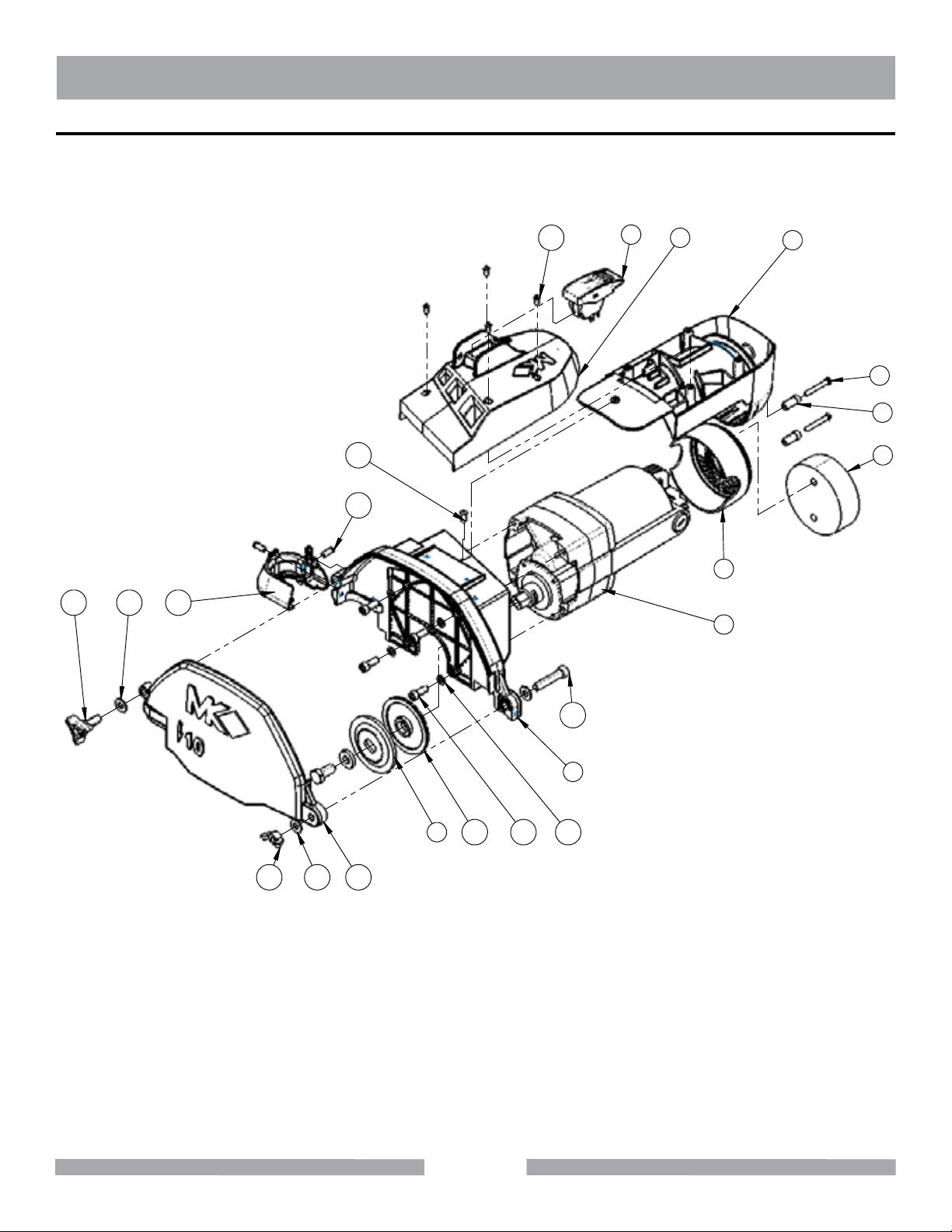
TX-3 GENERAL PRODUCT INFORMATION
PARTS LIST - ASSY, MOTOR - P/N 165029
14 18
13
21
19
20 7
8
6
4
3
5
2
1
15
9
1
121316
101117
33
Page 34
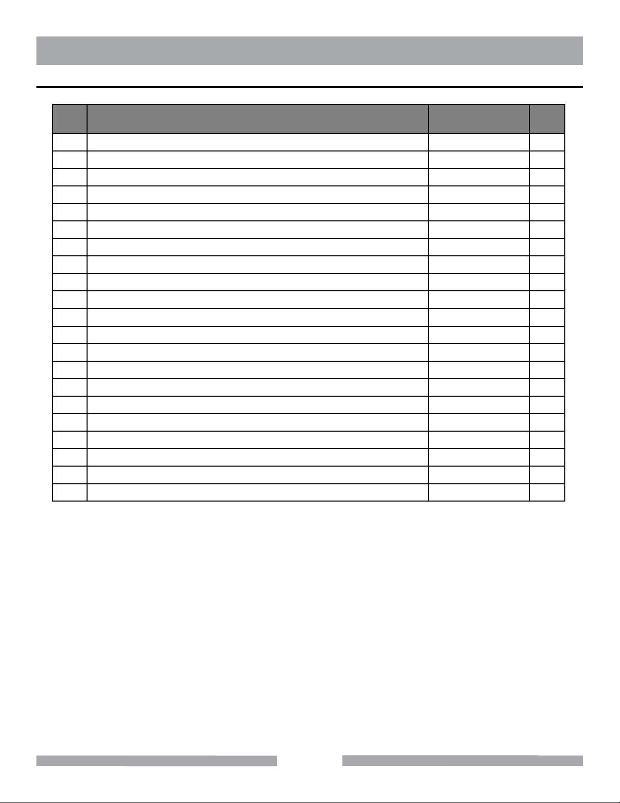
TX-3 GENERAL PRODUCT INFORMATION
PARTS LIST - ASSY, MOTOR - P/N 165029
ITEM
NO.
1 MOTOR & ACCESSORIES 157801-C 1
2 CAP, MOTOR 157877 1
3 SPACER, FILTER 157879 2
4 SCREW, PAN HD COMB SELF TAPPING, #8 X 1-1/2 158157 2
5 FILTER 157729 1
6 AFM, LOWER 166688 1
7 FILTER, AFM 166687 1
8 SWITCH, TOGGLE 164761 1
9 GUARD, INNER BLADE 164756 1
10 WASHER, SPLIT LOCK, M6 158159 4
11 SCREW, SOCKET HD CAP, M6 X 20 MM 166674 4
12 GUARD, OUTER BLADE 166661 1
13 WASHER, FLAT, M8 164855 3
14 KNOB, 3 PRONG, M8 X 23 MM 166662 1
15 SCREW, SOCKET HD CAP, M8 X 45 MM 165319 1
16 NUT, WING, M8 165320 1
DESCRIPTION
PART OR
IDENTIFYING NO.
OT Y.
REQ.
17 FLANGE, INNER 158106 1
18 MODULE, MISTING 164782 1
19 SCREW, SOCKET, BUTTON HEAD, M5 X 15 MM 165296 2
20 SCREW, PAN HD PHILLIP, M4 X 10 MM 164777 4
21 SCREW, PAN HD PHIL, M4 X 12 MM 164778 1
34
Page 35
TX-3 GENERAL PRODUCT INFORMATION
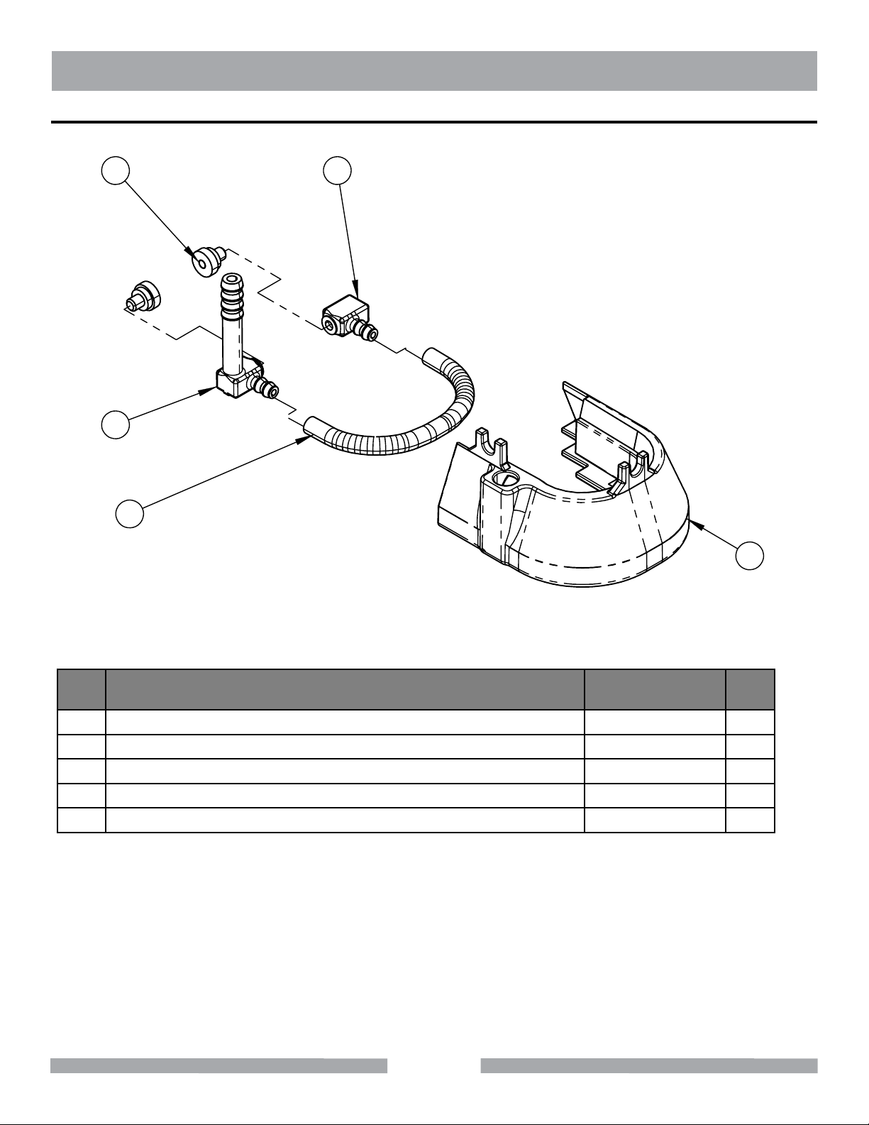
PARTS LIST - MODULE, MISTING - P/N 164782
5
3
2
4
1
ITEM
NO.
1 HOLDER, MISTING NOZZLE 166665 1
2 FITTING, END 166667 1
3 FITTING, 90-DEG ELBOW 166666 1
4 HOSE, PVC, 1/4 X 3/16 165314 1
5 NOZZLE, 0.3mm, 10-24 THREAD 164699-030 2
DESCRIPTION
35
PART OR
IDENTIFYING NO.
OT Y.
REQ.
Page 36
TX-3 GENERAL PRODUCT INFORMATION
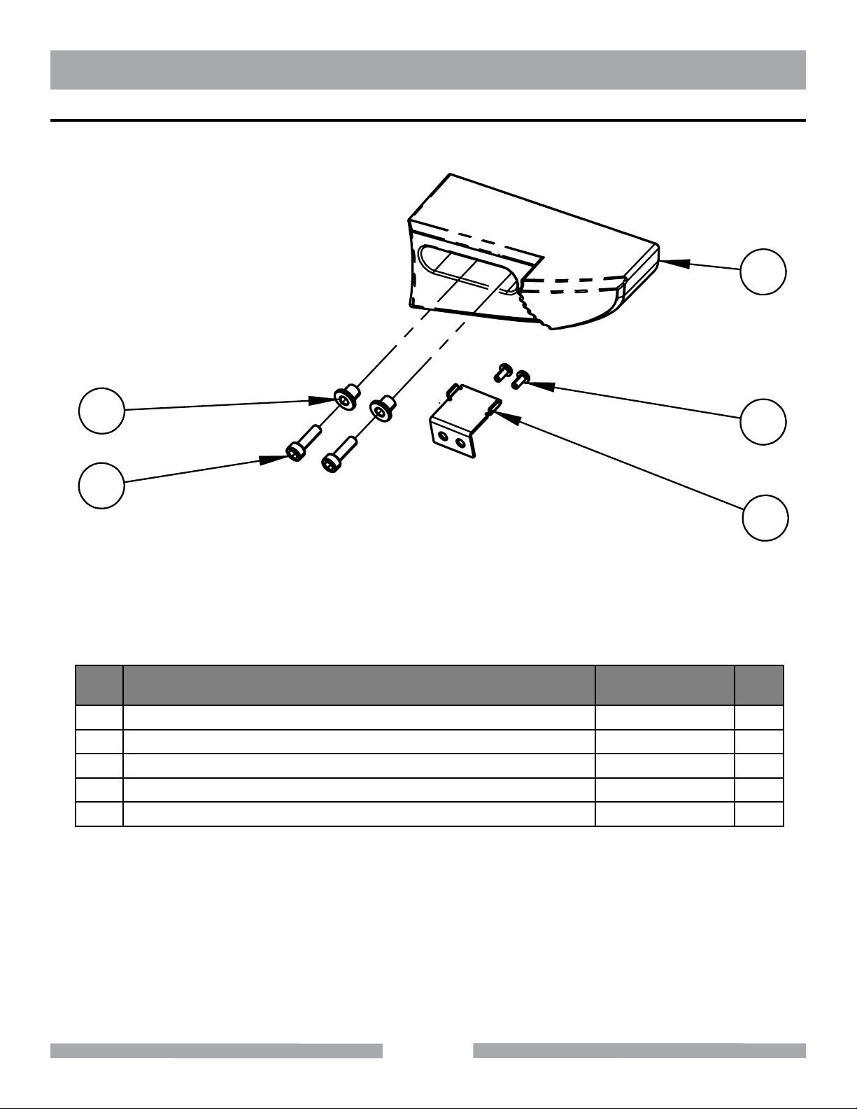
PARTS LIST - STOP, BLADE DEPTH - P/N 167135
1
4
5
ITEM
NO.
1 LEVER, PLUNGE LOCK 164848 1
2 SCREW, THD CUTTING, #4 X 1/4 165305 2
3 PLATE, PLUNGE LOCK 165306 1
4 SPACER, PLUNGE LOCK 165307 2
5 SCREW, SOCKET HD CAP, M4 X 14 165309 2
DESCRIPTION
PART OR
IDENTIFYING NO.
2
3
OT Y.
REQ.
36
Page 37
TX-3 GENERAL PRODUCT INFORMATION
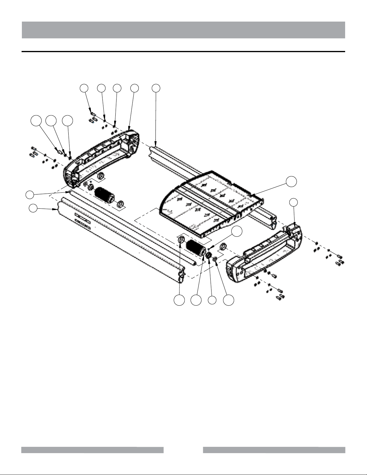
PARTS LIST - ASSY, LOWER FRAME - P/N 165294
5
43
17 15
16
67
12
8
2
1
13
14
11
10
9
37
Page 38
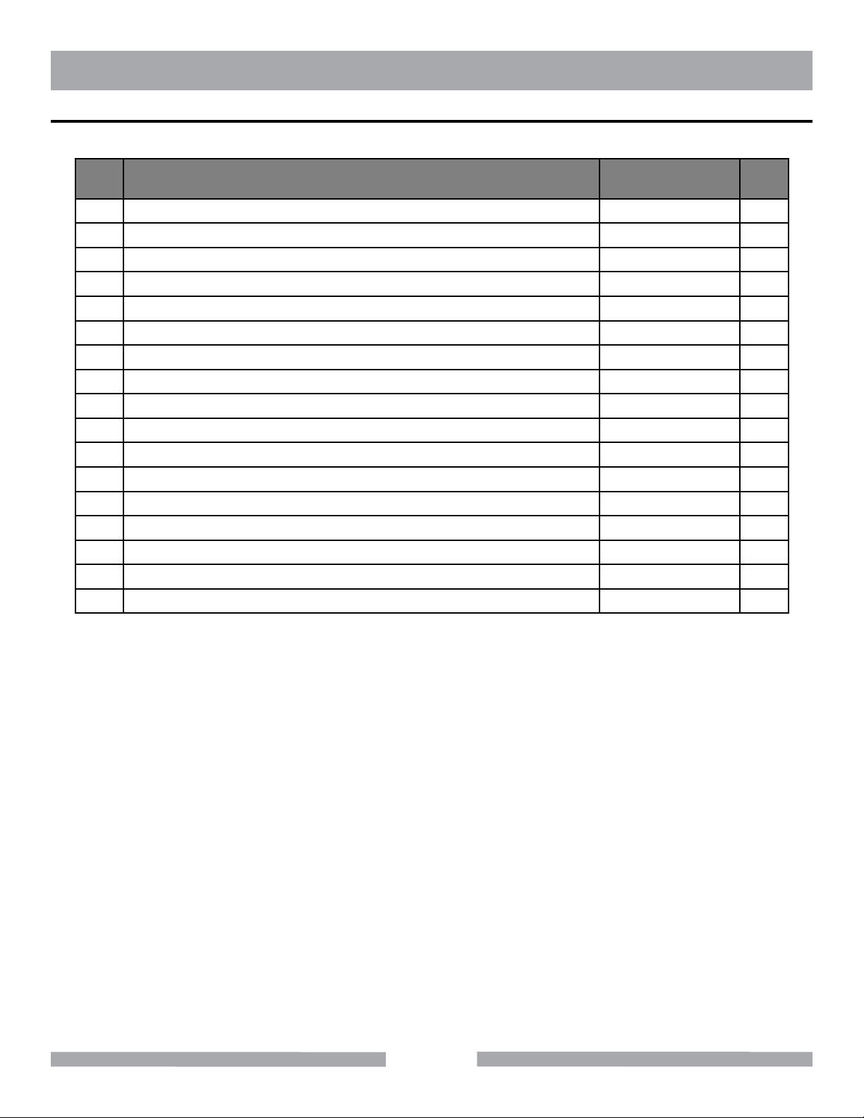
TX-3 GENERAL PRODUCT INFORMATION
PARTS LIST - ASSY, LOWER FRAME - P/N 165294
ITEM
NO.
1 RAIL, LEFT 166689 1
2 ASSY, FRONT ENDCAP 164854 1
3 RAIL, RIGHT 166690 1
4 ASSY, REAR ENDCAP 165353 1
5 WASHER, FLAT, M6 160215 12
6 WASHER, SPLIT LOCK, M6 158159 12
7 SCREW, SOCKET HD CAP, M6 X 26 MM 158268 12
8 BAR, GUIDE 164793 1
9 COLLAR, BELLOW 162064 2
10 O-RING, BUNA-N, 20 X 2.5 MM 165295 2
11 SCREW, SOCKET HD SET, M5 X 6 MM 165350 2
12 ASSY, TABLE 165293 1
13 CLAMP, HOSE, 11/16 TO 1- 1/4 X 1/2 162065 4
14 BELLOW, RUBBER 162066 2
15 WASHER, FLAT, M8 164855 2
16 WASHER, SPLIT LOCK, M8 164860 2
DESCRIPTION
PART OR
IDENTIFYING NO.
OT Y.
REQ.
17 SCREW, SOCKET HD CAP, M8 X 20 MM 160229 2
38
Page 39
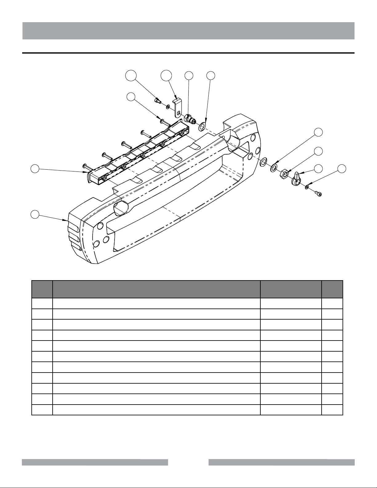
TX-3 GENERAL PRODUCT INFORMATION
PARTS LIST - ASSY, FRONT ENDCAP - P/N 164854
11 01 4
5
3
6
7
2
8
9
1
ITEM
NO.
1 ENDCAP, FRONT 164802 1
2 COVER, ENDCAP 164846 1
3 SCREW, PAN HD PHILLIP, M5 X 25 MM 160557 5
4 CYLINDER, TABLE LOCK 164836 1
5 WASHER, WAVE, M12 164856 2
6 WASHER, FLAT, M12 166678 1
7 NUT, JAM, M12 164857 1
8 KNOB, TABLE LOCK 164835 1
9 WASHER, FLAT, M5 164858 2
10 LOCK, TABLE 164834 1
11 SCREW, SOCKET HD CAP, M5 X 10 MM 160567 2
DESCRIPTION
PART OR
IDENTIFYING NO.
39
OT Y.
REQ.
Page 40
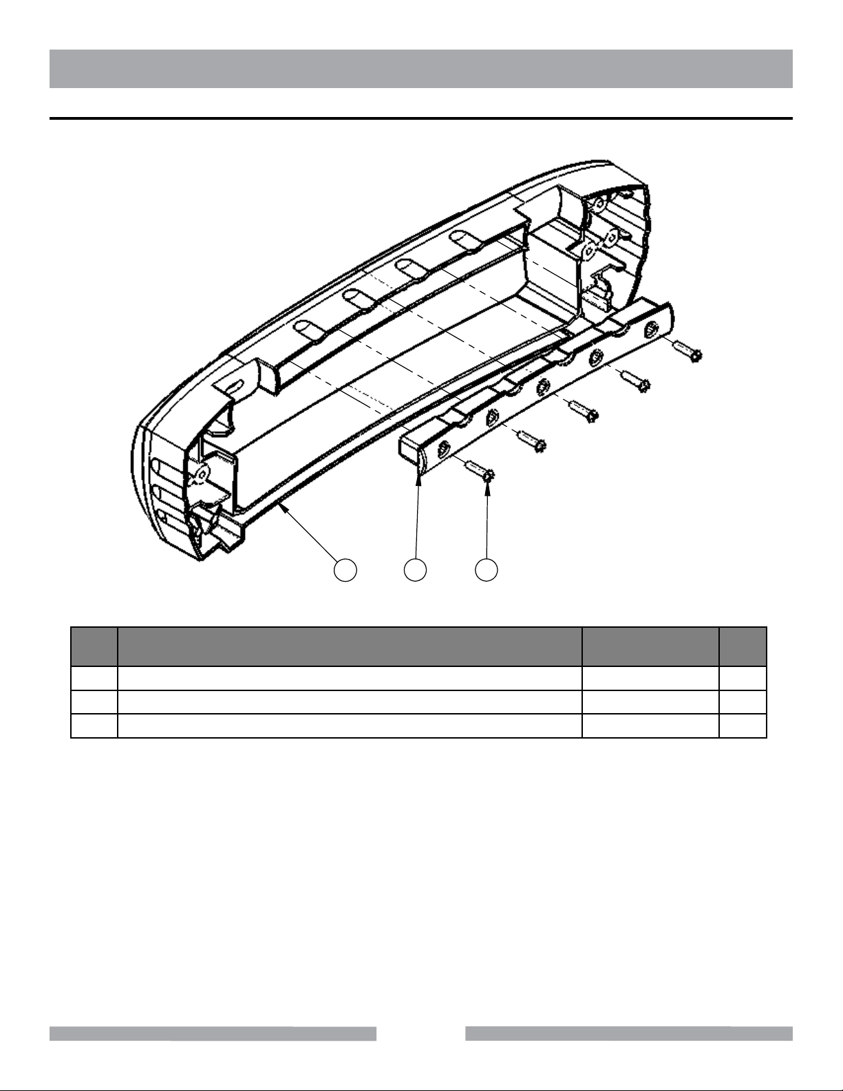
TX-3 GENERAL PRODUCT INFORMATION
PARTS LIST - ASSY, REAR ENDCAP - P/N 165353
1
ITEM
NO.
1 ENDCAP, REAR 164833 1
2 COVER, ENDCAP 164846 1
3 SCREW, PAN HD PHILLIP, M5 X 25 MM 160557 5
DESCRIPTION
32
PART OR
IDENTIFYING NO.
OT Y.
REQ.
40
Page 41
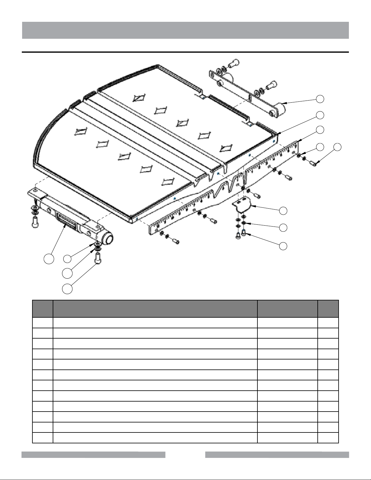
TX-3 GENERAL PRODUCT INFORMATION
PARTS LIST - ASSY, TABLE - P/N 165293
8
1
2
3
5
6
4
7
12
9
10
11
ITEM
NO.
1 TABLE 166682 1
2 FENCE, TABLE 164729 1
3 WASHER, FLAT, M5 164858 7
4 WASHER, SPLIT LOCK, M5 164859 7
5 SCREW, SOCKET, BUTTON HEAD, M5 X 15 MM 165296 5
6 PLATE, GUIDE, TABLE LOCK 164837 1
7 SCREW, SOCKET HD CAP, M5 X 10 MM 160567 2
DESCRIPTION
PART OR
IDENTIFYING NO.
OT Y.
REQ.
8 ASSY, ROLLER WHEEL BRACKET 165300 1
9 WASHER, FLAT, M8 164855 4
10 WASHER, SPLIT LOCK, M8 164860 4
11 SCREW, SOCKET HD CAP, M8 X 20 MM 160229 4
12 ASSY, LINEAR BEARING 165299 1
41
Page 42
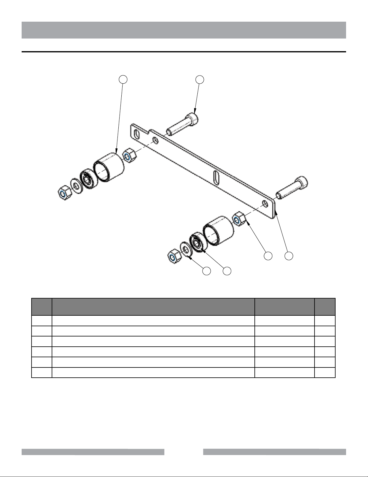
TX-3 GENERAL PRODUCT INFORMATION
PARTS LIST - ASSY, ROLLER WHEEL BRACKET - P/N 165300
5
2
13
46
ITEM
NO.
1 BRACKET, ROLLER WHEEL 164730 1
2 SCREW, SOCKET HD CAP, M5 X 35 MM 165311 2
3 NUT, HEX, M8 165030 4
4 BEARING, BALL, 608AS 166683 2
5 WHEEL, ROLLER 166672 2
6 WASHER, FLAT, M8 164855 2
DESCRIPTION
PART OR
IDENTIFYING NO.
OT Y.
REQ.
42
Page 43
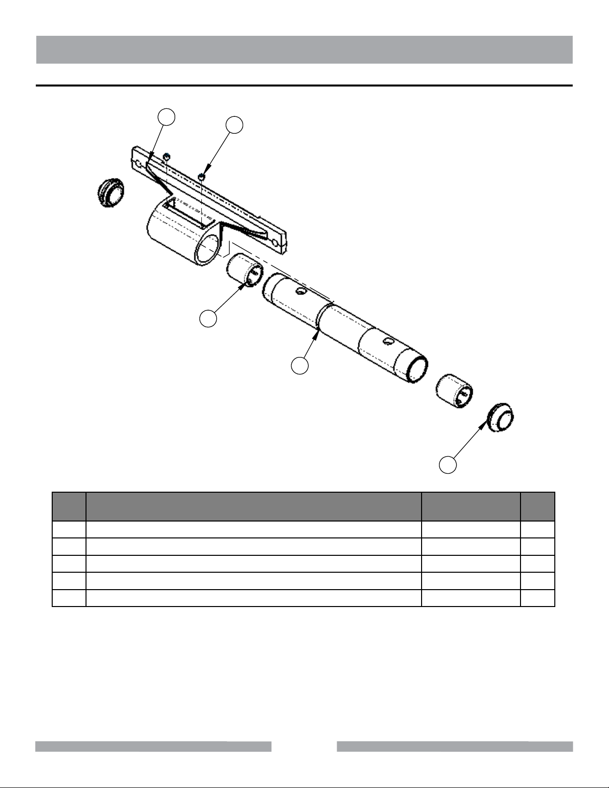
TX-3 GENERAL PRODUCT INFORMATION
PARTS LIST - ASSY, LINEAR BEARING - P/N 165299
1
3
4
2
5
ITEM
NO.
1 HOUSING, LINEAR BEARING 162062 1
2 BUSHING, LINEAR GUIDE 162063 1
3 SCREW, SOCKET HD SET, M5 X 6MM 165350 2
4 BEARING, SLEEVE 166671 2
5 CAP, GUIDE BUSHING 166673 2
DESCRIPTION
43
PART OR
IDENTIFYING NO.
OT Y.
REQ.
Page 44
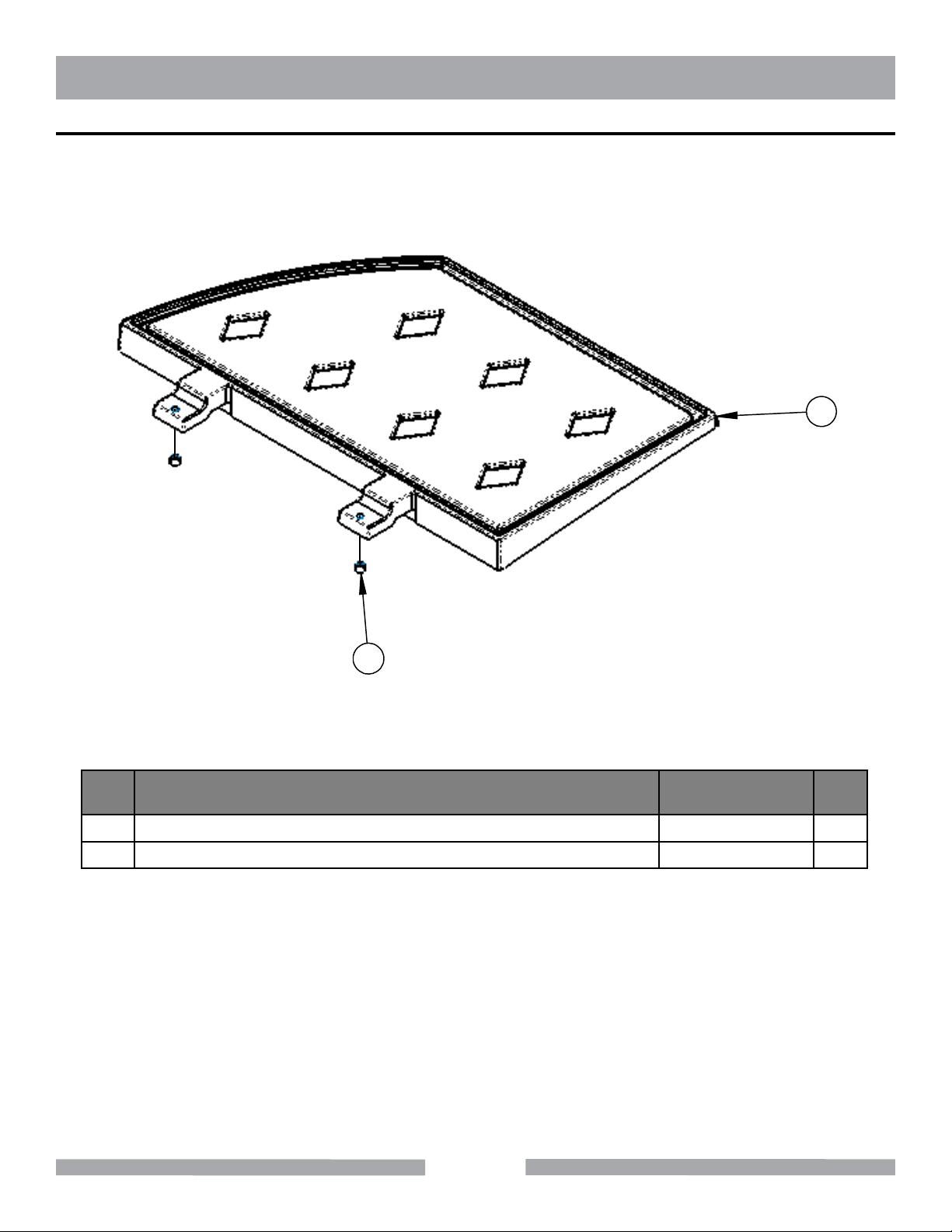
TX-3 GENERAL PRODUCT INFORMATION
PARTS LIST - ASSY, SIDE TABLE - P/N 165317
1
2
ITEM
NO.
1 TABLE. SIDE 166676 1
2 SCREW, SOCKET HD SET, M5 X 6 MM 165350 2
DESCRIPTION
PART OR
IDENTIFYING NO.
OT Y.
REQ.
44
Page 45
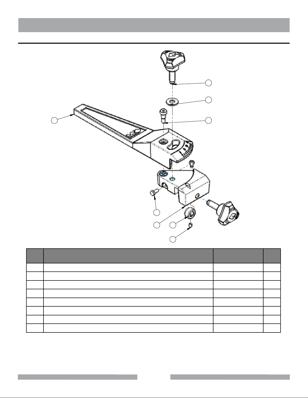
TX-3 GENERAL PRODUCT INFORMATION
PARTS LIST - ASSY, RIP GUIDE - P/N 165356
4
3
5
2
6
78
1
ITEM
NO.
1 SCREW, SOCKET HD SET, M4 X 6 MM 165313 1
DESCRIPTION
PART OR
IDENTIFYING NO.
OT Y.
REQ.
2 SCREW, SHOULDER, SOCKET CAP, M6 X 8 MM 154363 1
3 WASHER, FLAT, M8 164855 1
4 KNOB 165360 2
5 GUIDE 165357 1
6 SCREW, HEX HD CAP, M4 X 10 MM 165362 2
7 SEAT, CLAMPING 165361 1
8 BASE 165359 1
45
Page 46
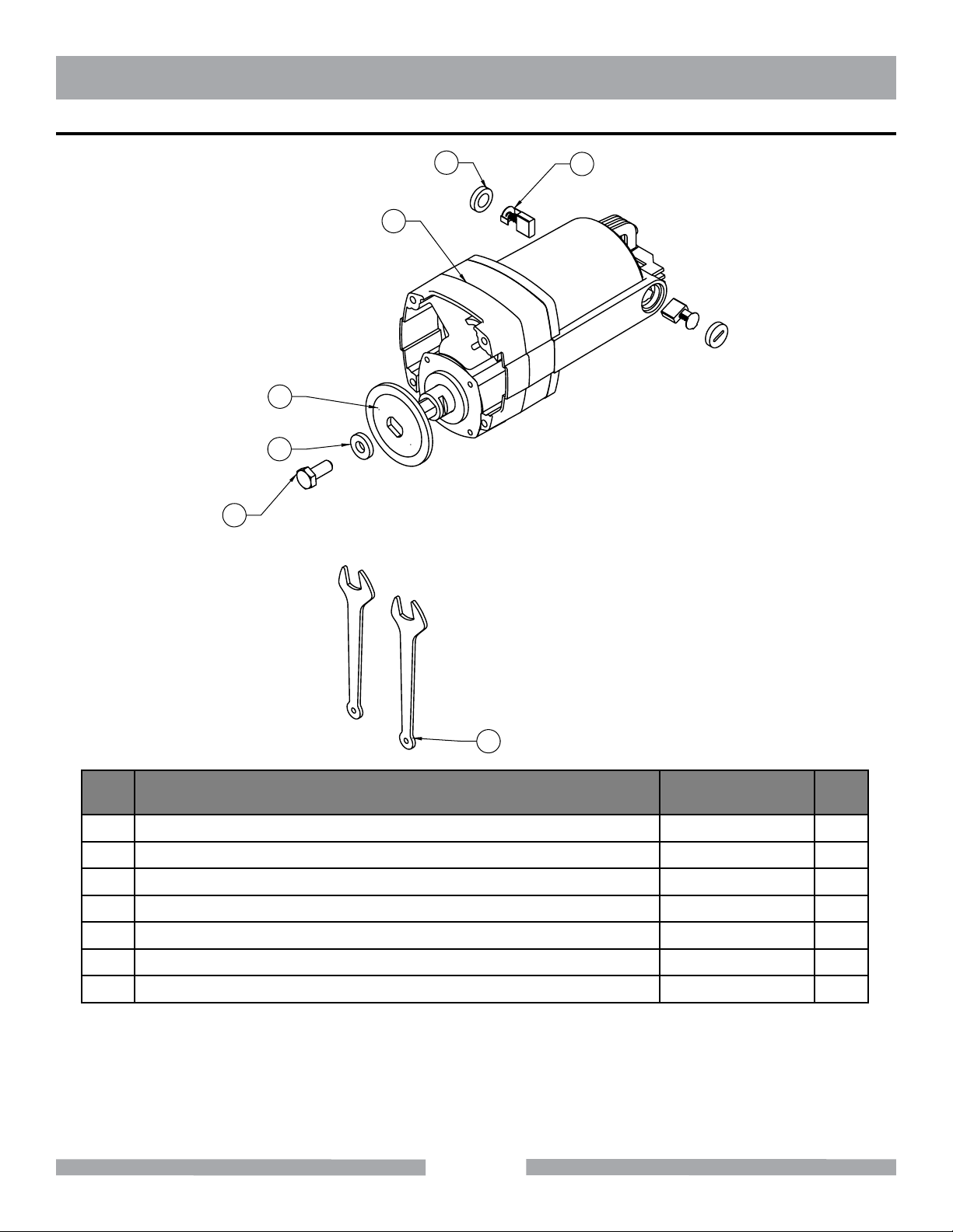
TX-3 GENERAL PRODUCT INFORMATION
PARTS LIST - MOTOR & ACCESSORIES - P/N 166232-C
7
1
2
3
4
6
5
ITEM
NO.
DESCRIPTION
PART OR
IDENTIFYING NO.
1 MOTO R 157801-C 1
2 FLANGE, OUTER 158105 1
3 WASHER, M10 166134 1
4 SCREW, HEX HD CAP, M10 X 20 MM 152272 1
5 WRENCH, 17 MM 158110 2
6 BRUSH, MOTOR 166228 2
7 CAP, MOTOR BRUSH 166229 2
46
OT Y.
REQ.
Page 47
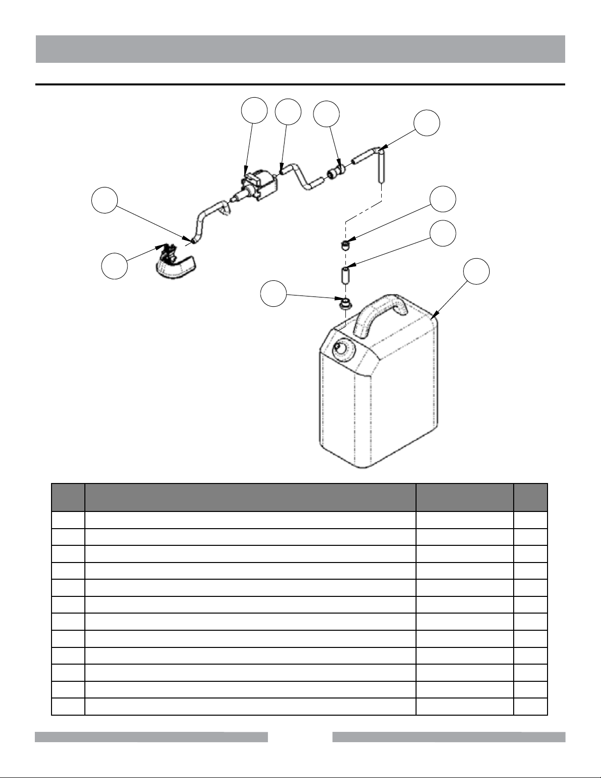
TX-3 GENERAL PRODUCT INFORMATION
PARTS LIST - MISTING KIT - P/N 166788
2
3
4
5
1
8
6
10
9
7
ITEM
NO.
1 TUBING, POLYURETHANE, 3/8 X .245 X 19 165008 1
2 PUMP 164693 1
3 TUBING, POLYURETHANE, 3/8 X .245 X 24 165005 1
4 COUPLING, PUSH-TO-CONNECT, 3/8 X 3/8 165004 1
5 TUBING, PVC, 3/8 X 1/4 X 51” 164692 1
6 TUBING, PVC, 1/2 X 3/8 X 1-1/2 165001 1
7 FILTER 164691 1
8 GROMMET 165003 1
9 CONTAINER, WATER 165002 1
10 MODULE, MISTING 164782 1
11 CARTON, OUTER (NOT SHOWN) 152566 1
12 INSTRUCTION SHEET (NOT SHOWN) 166788-IS 1
DESCRIPTION
PART OR
IDENTIFYING NO.
47
OT Y.
REQ.
Page 48
TX-3 NOTE PAGE
48
Page 49

TX-3 CONTACT AND LIMITED WARRANTY
ACCESSORIES, ORDERING AND RETURN INFORMATION
Ordering Information
You may order MK Diamond products through your local MK Diamond distributor or, you may order
direct from MK Diamond.
NOTE: There is a $25.00 minimum order when ordering direct from MK Diamond. All purchases must
be made using American Express,VISA or MasterCard.
When ordering direct from MK Diamond, please have the following information ready before calling:
• The Model Number of the machine
• The Serial Number of the machine
• Where the machine was purchased and when
• The Part Number for the part(s) being ordered
• The Part Description for the part(s) being ordered
All parts may be ordered by calling toll free to (800) 421-5830 or (310) 539-5221 and asking for
Customer Service. For technical questions, call (800) 474-5594 or (310) 257-2845.
Return Materials Policy
To expedite the service relative to the return of a product purchased through MK Diamond, please
observe the following:
NOTE: When returning items, they must have been purchased within the previous twelve (12) months.
• Have the Model Number of the machine
• Have the Serial Number of the machine
• Have the location of where the machine was purchased and when
• Contact Customer Service for approval to return the item(s)
• Follow the packaging instructions in the following section
• Ensure your item(s) are prepaid to the destination
For returned items, call toll free to (800) 421-5830 or (310) 539-5221 and asking for Customer
Service. For technical questions, call (800) 474-5594 or (310) 257-2845.
Packaging Instructions
• Package the part in its original container or one of comparable size
• Ensure all parts are secured in the packaging to prevent moving
Authorized Service Centers
For quicker repair time, you may contact MK Diamond Customer Service, toll free at (800) 421-5830
or (310) 539-5221 for the Authorized Service Center closest to you. For technical questions, call
(800) 474-5594.
49
Page 50

TX-3 CONTACT AND LIMITED WARRANTY
CONTACT:
Please contact MK Diamond Products, Inc. Customer Service Department with any questions you might have
regarding distributors, parts or service.
Customer Service Hours: Monday through Friday, 6AM-5PM PST
MK Diamond Products, Inc.
1315 Storm Parkway
Torrance, CA 90501
MK DIAMOND PRODUCTS, INC. LIMITED WARRANTY
MK DIAMOND PRODUCTS, INC. will guarantee every machine they build, to be free from defects in material
and workmanship for (1) one year from date of purchase. The obligation of MK DIAMOND PRODUCTS, INC.
under this warranty is limited to the repair or replacement of any parts which, under normal use, prove to be
defective in material or workmanship. The parts involved or the unit in question should be returned to MK
DIAMOND PRODUCTS, INC. or to a point designated by us, transportation prepaid.
This warranty does not obligate us to bear the cost of labor or transportation charges in connection with
replacement or repair of defective parts. Likewise, it shall NOT apply to any unit which has been subjected to
misuse, neglect or accident. This warranty does NOT apply to any machine which has been repaired or altered
outside our factory.
This warranty does NOT obligate MK DIAMOND PRODUCTS, INC., with respect to items not of our
manufacture, such as engines, motors, hydraulics, etc., which are subject to their own guarantees and warranties.
We shall in no event be liable for consequential damages or contingent liabilities arising out of failure of any
equipment or parts to operate properly.
© COPYRIGHT 2008, MK DIAMOND PRODUCTS, INC. ALL RIGHTS RESERVED.
The MK Diamond logo is a registered trademark of MK Diamond Products, Inc. and may not be used,
reproduced, or altered without written permission. All other trademarks are the property of their respective
owners and used with permission.
MK Diamond may have patents, patent applications, trade marks, copyrights of other intellectual property right
covering this product in this document.
This manual MUST accompany the equipment at all times. This manual is considered a permanent part of the
equipment and should remain with the unit if resold.
The information and specifications included in this publication were in effect at the time of approval for printing.
50
Page 51

TX-3 NOTE PAGE
51
Page 52

TX-3 TILE SAW
OPERATION & PARTS MANUAL
DOCUMENT NO. 165808
MK Diamond Products, Inc.
1315 Storm Parkway
Torrance, CA 90501
Toll-Free: (800) 845-3729
Phone: (310) 539-2221
Fax: (310) 539-5158
www.mkdiamond.com
 Loading...