

Page 1

www.mkdiamond.com
MK-SCARIFIER
OWNER’S MANUAL, PARTS LIST &
OPERATING INSTRUCTIONS
SG-9
SG-5
Revision 105
Manual Part# 158537
Caution: Read all safety and operating instructions
before using this equipment. This owner’s manual
MUST accompany the equipment at all times.
01.2014
Page 2

INTRODUCTION
Congratulations on your purchase of a MK-Scarier. We are certain that you will be pleased with
your purchase. MK Diamond takes pride in producing the nest construction power tools and diamond blades in the industry.
Operated correctly, your MK-Scarier should provide you with years of service. In order to help you,
we have included this manual. This owners manual contains information necessary to operate and
maintain your MK-Scarier safely and correctly. Please take the time to familiarize yourself with the
MK-Scarier by reading and reviewing this manual.
Read and follow all safety, operating and maintenance instructions.
If you should have questions concerning your MK-Scarier please feel free to call our friendly
customer service department at (800) 421-5830.
Regards,
MK Diamond
NOTE THIS INFORMATION FOR FUTURE USE:
MODEL NUMBER:
SERIAL NUMBER:
PURCHASE PLACE:
PURCHASE DATE:
NOTE: For your (1) one year warranty to be effective, complete the warranty card
(including the Serial Number) and mail it in as soon as possible.
2
Page 3

TABLE OF CONTENTS
SAFETY PAGE
Safety Messages 4
Damage Prevention Message 4
General Safety Precautions and Hazard Symbols 4-7
California Proposition 65 Message 8
Electrical Requirements and Grounding Instructions 9
Electric Motor Safety 10-11
Safety Label Locations 12
Specic Warnings 13
Product Specications 13
UNPACKING ASSEMBLY
Unpacking 14
Contents 14
Transport 14
Handlebar 15
SCARIFIER DRUM
Scarier Drum Cutter 16
Drum Conguration 17-18
Assembly 19-20
ASSEMBLY
Assembly 21-26
SETUP
Vacuum Setup 26
Pre-start Inspection 27
Setup 28-29
Operation 30-31
Cleanup 31-32
MAINTENANCE
Maintenance 32-48
EXPLODED VIEW & PARTS LIST
Exploded View & Parts List 50-59
DRUM ASSEMBLIES
Exploded View & Parts List 60-63
THEORY
Theory of Scarifying 64
ACCESSORIES
Accessories 65
ORDERING & RETURN INSTRUCTIONS
Ordering Information 66
Return Material Policy 66
CONTACT & LIMITED WARRANTY
Contact 67
Limited Warranty 67
3
Page 4
MK-SCARIFIER SAFETY
ON
(
(
)
)
ON
(
(
)
)
ON
(
(
)
)
ON
(
(
)
)
Read and follow all safety, operating and maintenance instructions. Failure to read and follow
these instructions could result in injury or death to you or others. Failure to read and follow these
instructions could also result in damage and/or reduced equipment life. Safety warnings and
guidelines do not by themselves eliminate danger. They are not substitutes for proper accident
prevention procedures and good judgement.
SAFETY MESSAGES
A safety message alerts you to potential hazards that could hurt you or others. Each safety message is
preceded by a safety alert symbol ( ) and one of three words: DANGER, WARNING, or CAUTION.
DANGER You WILL be KILLED or SERIOUSLY INJURED if you DO NOT follow directions.
WARNING
You CAN be KILLED or SERIOUSLY INJURED if you DO NOT follow directions.
You CAN be INJURED if you DO NOT follow directions. It may also be used to
CAUTION
alert against unsafe practices.
DAMAGE PREVENTION AND INFORMATION MESSAGES
A Damage Prevention Message is to inform the user of important information and/or instructions that
could lead to equipment or other property damage if not followed. Information Messages convey
information that pertains to the equipment being used. Each message will be preceded by the word
NOTE, as in the example below.
NOTE:
Equipment and/or property damage may result if these instructions are not followed.
GENERAL SAFETY PRECAUTIONS AND HAZARD SYMBOLS
In order to prevent injury, the following safety precautions and symbols should be followed at all times!
ALWAYS read this Owner’s Manual before operating the machine. DO NOT operate or
service this equipment before reading this entire manual. Read and understand all warnings, instructions and controls on the machine. Know how to stop the equipment quickly in
case of emergency. It is the operators responsibility to use this machine under safe working conditions and conform with federal, state and local codes or regulations pertaining to
safety, air, pollution, noise etc...
ALWAYS keep the Blade and Belt Guards in place. DO NOT operate this machine with any
guard or safety device removed. A Guard, or any damaged part should be repaired or
replaced immediately.
REMOVE ADJUSTING KEYS AND WRENCHES
Form a habit of checking to see that keys and adjusting wrenches are removed from the
power tool before it is turned on.
KEEP WORK AREA CLEAN
Cluttered work areas and benches invite accidents.
DO NOT USE IN DANGEROUS PLACES
DO NOT use power tools in damp or wet locations nor expose them to rain. Always keep
the work area well lighted.
4
Page 5
MK-SCARIFIER SAFETY
KEEP CHILDREN AWAY
All visitors and children should be kept a safe distance from work area.
MAKE THE WORKSHOP KID PROOF
Make the workshops kid proof by using padlocks, master switches or by removing starter keys.
DO NOT FORCE THE TOOL
A power tool will do a job better and safer operating at the rate for which it was designed.
USE THE RIGHT TOOL
DO NOT force a tool or an attachment, to do a job that it was not designed to do.
USE THE PROPER EXTENSION CORD
If using an extension cord make sure it is in good condition rst. When using an extension
cord, be sure to use one heavy enough to carry the current your product will draw. An undersized cord will cause a drop in line voltage that will result in a loss of power and overheating.
Page 9 shows the correct AWG size to use depending on cord length and nameplate ampere
rating. If in doubt, use the next heavier gauge. The smaller the gauge number, the heavier
the cord.
USE PROPER APPAREL
DO NOT wear loose clothing, gloves, neckties, rings, bracelets, or other jewelry that may be
caught in moving parts. Non-slip footwear is recommended. Wear protective hair covering to
contain long hair.
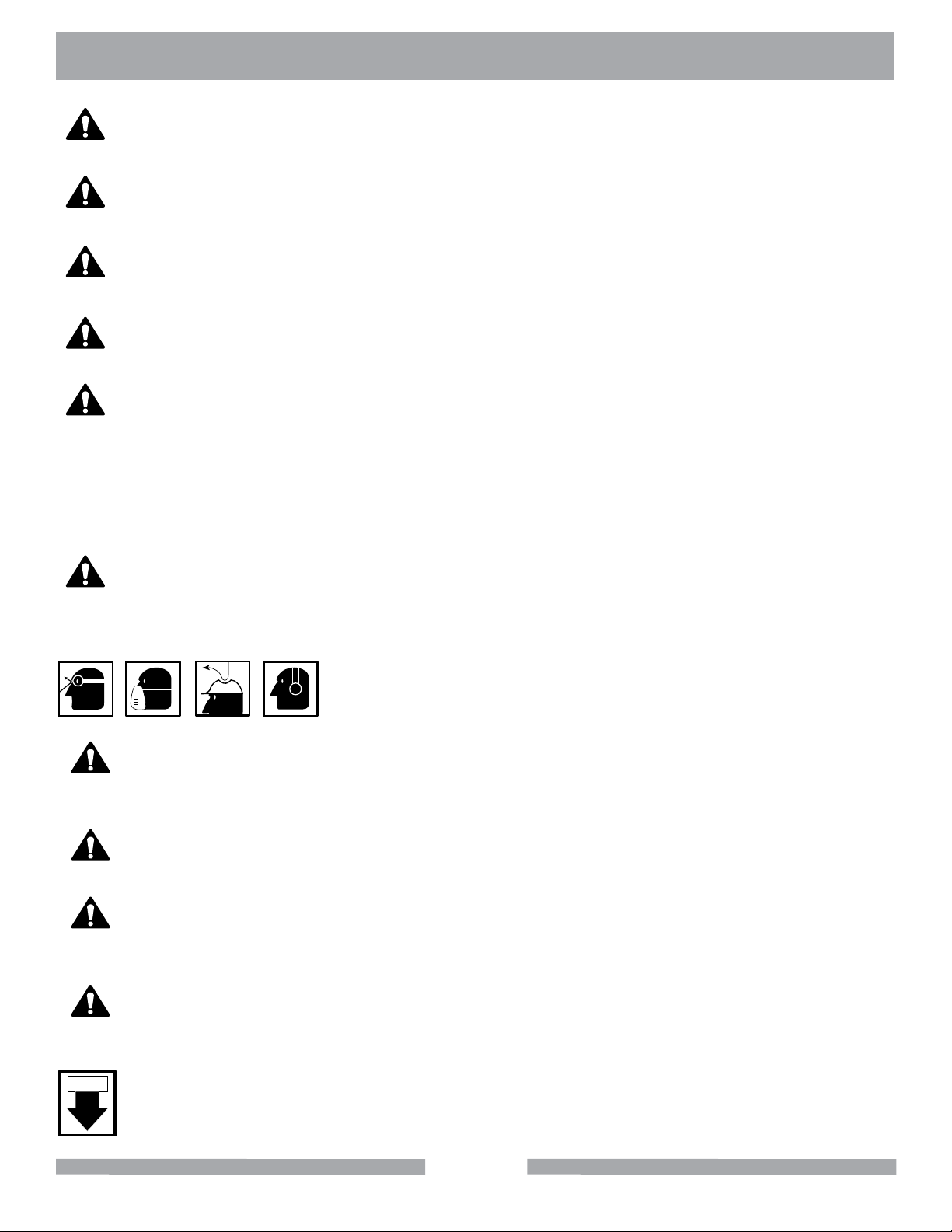
PERSONAL PROTECTIVE EQUIPMENT
ALWAYS wear approved respiratory, head, ear and eye protection
when operating this machine.
SECURE WORK
Clamps or a vise should be used to hold work whenever practical. Keeping your hands free
to operate a power tool is safer.
DO NOT OVERREACH
Keep proper footing and balance at all times by not overreaching.
MAINTAIN TOOLS WITH CARE
Keep tools clean for the best and safest performance. Always follow maintenance instructions for lubricating, and when changing accessories.
DISCONNECT TOOLS
Power tools should always be disconnected before servicing or when changing accessories,
such as blades, bits, cutters, and the like.
ON / OFF
ALWAYS place the power ON/OFF switch in the OFF position when the saw is not in use.
5
Page 6

MK-SCARIFIER SAFETY
USE RECOMMENDED ACCESSORIES
Consult the owner’s manual for recommended accessories. Using improper accessories
may increase the risk of personal or by-stander injury. Unauthorized equipment
modifications will void all warranties. Manufacturer does not assume responsibility for any
accident due to equipment modifications.
AlwAys ensure that the machine is on level ground before using.
NEVER STAND ON THE TOOL
Serious injury could occur if a power tool is tipped, or if a cutting tool is unintentionally contacted.
TRANSPORT
When loading or unloading the machine, use caution. Remove the blade prior to hoisting,
loading and transporting the machine.
CHECK FOR DAMAGED PARTS
Before using a power tool, check for damaged part. A guard or any other part that is damaged
should be carefully checked to determine if would operate properly and perform its intended
function. Always check moving parts for proper alignment or binding. Check for broken parts
and mountings and all other conditions that may affect the operation of the power tool. A
guard, or any damaged part, should be properly repaired or replaced.
DIRECTION OF ROTATION
A blade or cutter should always be installed so that rotation is in the direction of the
arrow imprinted on the side of the blade or cutter. It should correspond with the rotational
direction of the motor. Always feed work into a blade against the direction of rotation.
NEVER LEAVE A TOOL UNATTENDED
TURN POWER OFF - Do not leave a tool until it comes to a complete stop. Always turn a
power tool OFF when leaving the work area, or, when a cut is nished.
NEVER disconnect any "emergency or safety devices". These devices are intended for
operator safety. Disconnection of these devices can cause severe injury, bodily harm, or
even death! Disconnection of any of these devices will void all warranties. Unauthorized
equipment modifications will void all warranties. Manufacturer does not assume
responsibility for any accident due to equipment modifications.
NEVER operate this equipment when not feeling well due to fatigue, illness or taking medicine.
Check the chemical properties of the material to be cut/grinded and follow all EPA/OSHA
Regulations.
6
Page 7

MK-SCARIFIER SAFETY
(
(
)
)
WARNING
Diamond Blades improperly used are dangerous. Comply with American National Standards Institute
Safety Code, B7.1 and, Occupational Safety and Health Act covering Speed, Safety Guards, Flanges,
Mounting Procedures, General Operating Rules, Handling, Storage and General Machine Conditions
ELECTRICAL SHOCK
NEVER touch electrical wires or components while the engine is running. Exposed,
frayed or worn electrical wiring and plugs can be sources of electrical shock which could
cause severe injury or burns. Do not touch the plug with wet hands.
ROTATING PARTS
Keep hands, feet, hair, and clothing away from all moving parts to prevent injury. Never
operate the motor with covers, shrouds, or guards removed.
OVER SPEED
NEVER tamper with the governor components or settings to increase the maximum
speed. Severe personal injury and damage to the engine or equipment can result if operated at speeds above maximum.
DO NOT EXPOSE TO RAIN
DO NOT expose to rain or use in damp locations.
7
Page 8

MK-SCARIFIER SAFETY
SILICA DUST WARNING
Grinding/cutting/drilling of masonry, concrete, metal and other materials with silica in their composition
may give off dust or mists containing crystalline silica. Silica is a basic component of sand, quartz,
brick clay, granite and numerous other minerals and rocks. Repeated and/or substantial inhalation of
airborne crystalline silica can cause serious or fatal respiratory diseases, including silicosis. In addition, California and some other authorities have listed respirable crystalline silica as a substance
known to cause cancer. When cutting such materials, always follow respiratory precautions.
Use appropriate NIOSH-approved respiratory protection where dust hazard may occur. Paper masks
or surgical masks without a NIOSH approval number are not recommended because they do little to
protect the worker. For more information about respirator programs, including what respirators have
received NIOSH approval as safe and effective, please visit the NIOSH website at:
http://www.cdc.gov/niosh/topics/respirators
Observe OSHA regulations for respirator use (29 C.F.R.§1910.134 and §1503.1).
Visit http://www.osha.gov for more information.
CALIFORNIA PROPOSITION 65 MESSAGE
Some dust created by power sanding, sawing, grinding, drilling, and other construction activities contain chemicals known (to the State of California) to cause cancer, birth defects or other reproductive
harm. Some examples of these chemicals are:
• Lead, from lead-based paints
• Crystalline silica from bricks, cement and other masonry products
• Arsenic and chromium, from chemically treated lumber
For further information, consult the following sources:
http://www.osha.gov/dsg/topics/silicacrystalline/index.html
http://www.cdc.gov/niosh/docs/96-112/
http://oehha.ca.gov/prop65/law/P65law72003.html
http://www.dir.ca.gov/Title8/sub4.html
Your risk from these exposures varies depending on how often you do this type of work. To reduce
your exposure to these chemicals, work in a well-ventilated area, and work with approved safety
equipment, such as dust masks that are specially designed to lter out microscopic particles. Where
use of a dust extraction device is possible, it should be used. To achieve a high level of dust collection, use an industrial HEPA vacuum cleaner. Observe OSHA 29 CFR part 1926.57 and 1926.103.
WARNING
Sawing, grinding and drilling generate dust. Excessive airborne particles may cause irritation to eyes,
skin and respiratory tract. To avoid breathing impairment, always employ dust controls and protection
suitable to the material being sawed or drilled; See OSHA (29 CFR Part 1910.1200).
8
Page 9
MK-SCARIFIER SAFETY
ELECTRICAL REQUIREMENTS AND GROUNDING INSTRUCTIONS
In order to prevent potential electrical shock and injury, the following electrical safety precautions and
symbols should be followed at all times!
WARNING
In case of a malfunction or breakdown, grounding provides a path of least resistance for electric current to reduce the risk of electric shock. This tool is equipped with an electric cord having an equipment-grounding conductor and a grounding plug. The plug must be plugged into a matching outlet
that is properly installed and grounded in accordance with all local codes and ordinances.
• Do not modify the plug provided – if it will not t the outlet; have the proper outlet installed by a
qualied electrician
• Improper connections of the equipment-grounding conductor can result in a risk of electric
shock. The equipment-grounding conductor is the insulated conductor that has an outer
surface that is green, with or without yellow stripes. If repair or replacement of the electric cord
or plug is necessary, do not connect the equipment-grounding conductor to a live terminal
• Check with a qualied electrician or service personnel if the grounding instructions are not
completely understood, or if in doubt as to whether the tool is properly grounded
• Use only 3-wire extension cords that have 3-prong grounding plugs and 3-pole receptacles that
accept the tool’s plug
• Repair or replace a damaged or worn cord immediately
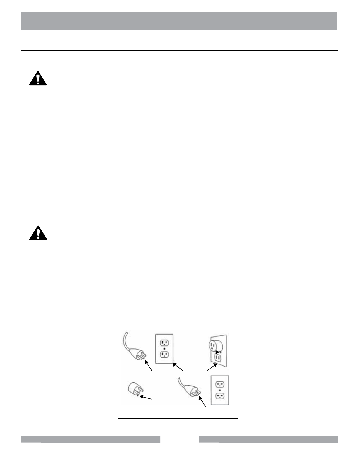
WARNING
This tool is intended for use on a circuit that has an outlet that looks like the one shown in Sketch A.
The tool has a grounding plug that looks like the plug illustrated in Sketch A. A temporary adapter,
which looks like the adapter illustrated in sketches B and C, may be used to connect this plug to a
2-pole receptacle as shown in Sketch B, if a properly grounded outlet is not available. The temporary
adapter should be used only until a properly grounded outlet can be installed by a qualied electrician. The green-colored rigid ear, lug, and the like, extending from the adapter, must be connected to
a permanent ground such as a properly grounded outlet box.
NOTE: Use of a temporary adapter is not permitted in Canada.
Metal Screw
Grounding
Pin
(A)
ADAPTER
Grounding
Means
(C)
Cover of
Grounded
Outlet Box
Grounding
Pin
(B)
(D)
Circuit and Adapter Information
9
Page 10
MK-SCARIFIER SAFETY
ON
(
(
)
)
ON
(
(
)
)
ON
(
(
)
)
ON
(
(
)
)
ON
(
(
)
)
ELECTRIC MOTOR SAFETY
For maintenance care and operation of the electric motor, refer to your electric motor instruction booklet furnished with the electric motor. Protect the electric motor from dust as much as possible and keep
ventilating openings clean. Before plugging in the machine, make sure that the outlet voltage is within
the voltage marked on the machines's data plate.
CAUTION
DO NOT spray water on the electric motor. DO NOT touch the plug with wet hands. To reduce
the risk of electrocution, keep all connections dry and off the ground.
DO NOT operate electric motor in an explosive environment.
DO NOT EXPOSE TO RAIN
DO NOT expose to rain or use in damp locations.
WARNING
If operating the equipment in damp locations is unavoidable, ALWAYS use a Ground Fault
Circuit Interrupter, ALWAYS wear rubber gloves and footwear in damp conditions.
DO NOT abuse the cord. Never use the cord to carry the equipment or to pull the plug from
the outlet. Keep the cord away from heat, sharp edges, and moving parts. Replace damaged cords immediately. Damaged cords increase the risk of electric shock.
WARNING
To reduce the risk of electrocution, keep all connections dry and off the ground. A Ground Fault
Circuit Interrupter (GFCI) should be provided on the circuit(s) or outlet(s) to be used for this
machine. Receptacles are available having built-in GFCI protections and may be used for this
measure of safety. When using an extension cord, GFCI should be installed closest to the power
source, followed by the extension cord and lastly, the machine.
WARNING
The water pump requires a GFCI. To reduce risk of electrical shock when operating the machine
with the pump plugged into the 3-pole receptacle on the motor, connect the saw to a GFCI outlet.
See the pump manual and informational tags enclosed separately for all pump information.
WARNING
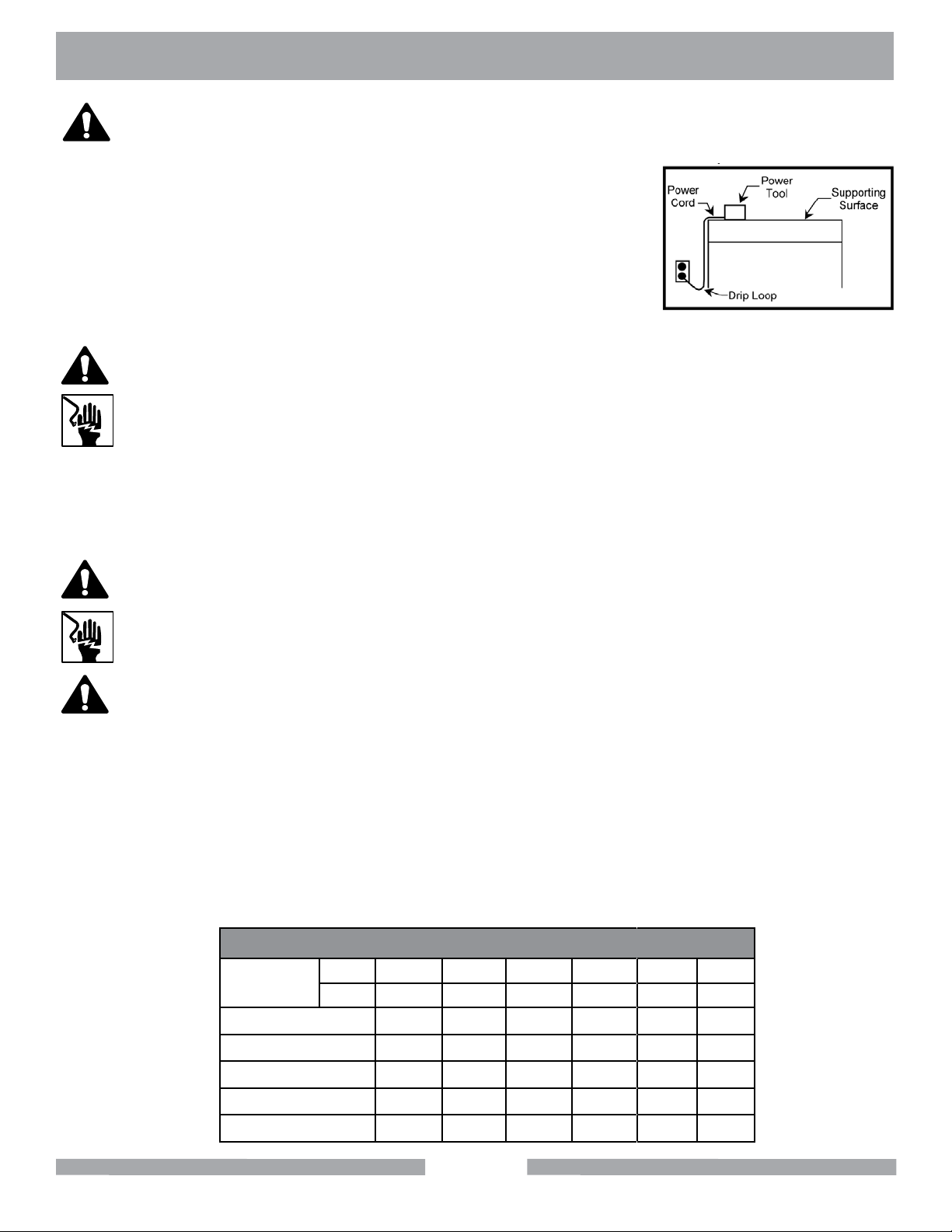
To avoid the possibility of the appliance plug or receptacle getting wet, position the machine to one
side of a wall mounted receptacle. This will prevent water from dripping onto the receptacle or plug. A
“drip loop,” shown in the picture below, should be arranged by the user to properly position the power
cord relative to the power source.
10
Page 11
MK-SCARIFIER SAFETY
WARNING
The “drip loop” is that part of the cord below the level of the receptacle,
or the connector, if an extension cord is used. This method of positioning the cord prevents the travel of water along the power cord and
coming in contact with the receptacle.
If the plug or receptacle gets wet, DO NOT unplug the cord. Disconnect the fuse or circuit breaker that supplies power to the tool. Then
unplug and examine for presence of water in the receptacle.
WARNING
Use only extension cords that are intended for outdoor use. These extension cords are
identied by a marking “Acceptable for use with outdoor appliances; store indoors while not
in use." Use only extension cords having an electrical rating not less than the rating of the
product. Do not use damaged extension cords. Examine extension cords before using and
replace if damaged. Do not abuse extension cords and do not yank on any cord to disconnect. Keep cords away from heat and sharp edges. Always disconnect the extension cord
from the receptacle before disconnecting the product from the extension cord.
Drip Loop Information
WARNING
To reduce the risk of electrocution, keep all connections dry and off the ground. Do not touch
the plug with wet hands.
WARNING
Use of under sized extension cords result in low voltage to the motor that can result in motor burnout and premature failure. MK Diamond warns that equipment returned to us showing
signs of being run in a low voltage condition, through the use of undersized extension cords will
be repaired or replaced totally at the customer's expense. There will be no warranty claim.
To choose the proper extension cord,
• Locate the length of extension cord needed in the table below.
• Once the proper length is found, move down the column to obtain the correct AWG
size required for that length of extension cord.
EXTENSION CORD LENGTH
Nameplate
Amperes
0 - 5 16 16 16 14 12 12
115V 25' 50' 75' 100' 150' 200'
250V 50' 100' 150' 200' 300' 400'
5.1 - 8 16 16 14 12 10 •
8.1 - 12 14 14 12 10 • •
12.1 - 15 12 12 10 10 • •
15.1 - 20 10 10 10 • • •
11
Page 12
MK-SCARIFIER SAFETY
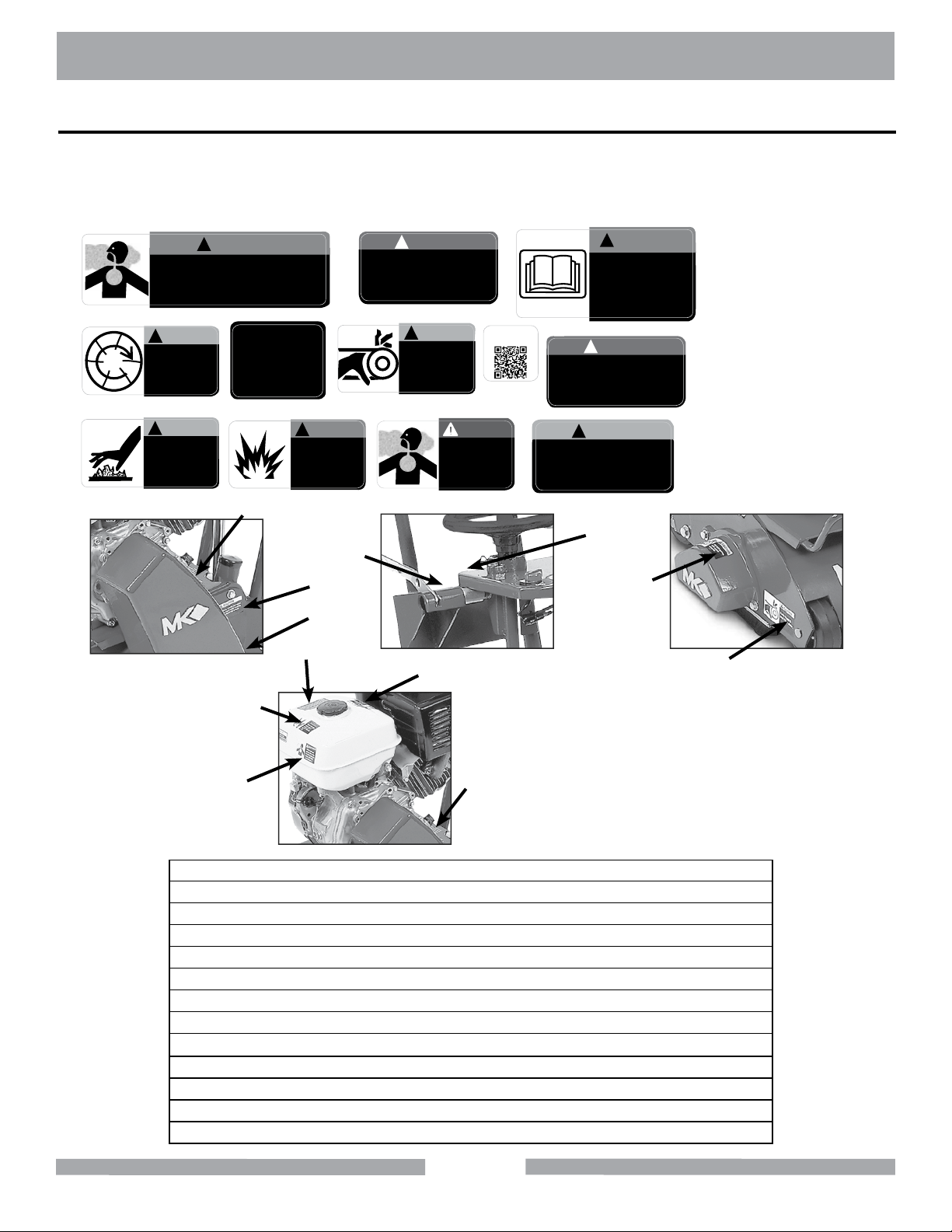
SAFETY LABEL LOCATIONS
Safety labels contain important safety information. Please read the information contained on each
safety label. These labels are considered a permanent part of your saw. If a label comes off or
becomes hard to read, contact MK Diamond or your dealer for a replacement.
Grinding/cutting/drilling of masonry, concrete, metal and other materials with silica in
their composition may give off dust or mists containing crystalline silica. Silica is a basic
component of sand, quartz, brick clay, granite and numerous other minerals and rocks.
Repeated and/or substantial inhalation of airborne crystalline silica can cause serious
or fatal respiratory diseases, including silicosis. In addition, California and some other
authorities have listed respirable crystalline silica as a substance known to cause cancer.
!
Keep
hands and
feet clear.
Label D
!
DO NOT
touch hot
surface.
Label I
Label A
CAUTION
CAUTION
!
WARNING
SERVICE OR
WARRANTY
FOR INFORMATION ON
PLEASE CALL
1-800-474-5594
Label E
WARNING
!
When refueling
stop engine and
allow to cool.
DO NOT overll
tank.
Label J Label K
NOTICE
!
Overtensioning of belts
will result in premature
crank and/or bearing failure.
Label B
CAUTION
!
DO NOT
operate without
guards in place.
Label F
DANGER
Lethal exhaust
gases. Use only
in well ventilated
areas. DO NOT
use indoors.
For manuals and parts
lists scan the QR code
with your smart phone
Label G
The exhaust from this product
contains chemicals known to
the State of California to cause
cancer, birth defects or other
reproductive harm.
Accidental start hazard.
Disconnect spark plug
prior to servicing.
!
DO NOT operate
this equipment
before reading
the owner’s
manual!
Label C
DANGER
!
Label H
CAUTION
!
Label L
WARNING
Warning Sheet
Part # 166010
Label A
Label E
Label C
Label B
Label D
Label G
Label H
Label I
Label F
Label J
Label K
Label L
Decal/Label Location Description
A Belt Guard - Side Warning - Silica Warning
B Belt Guard - Side Notice - Overtension of the belts
C Console Warning - Read Owner’s Manual
D Belt Guard Caution - Keep Hands & Feet Clear
E Console Service or Warranty
F Belt Guard Caution - Guards in place
G Belt Guard QR Code for Manual
H Gas Tank - Top Danger - State of California
I Gas Tank - Top Caution - Do Not Touch
J Gas Tank - Side Warning - Do Not OVerfill Tank
K Gas Tank - Side Danger - Silica Warranty
L Cutting Drum Caution - Spack Plug
12
Page 13

MK-SCARIFIER PRODUCT SPECIFICATIONS
SPECIFIC WARNINGS
• Read Owners Manual
• Wear Protective Gear for Head, Lungs, Ears and Eyes
PRODUCT SPECIFICATION
Operated and used according to this manual, the Scarier will provide years of dependable service.
General Description
The Scariers are is engineered with an 8” Cutting Drum. The SG-9 has a Honda engine and the
SG-5 has a Baldor motor. The scarier is designed with ne depth control allowing the operator to
make depth adjustments in 1/16-inch increments.
MotorandWeightSpecications
The Scariers use a 6-inch diameter, 8-inch long cutting drum with 6 hardened steel shafts that will
accommodate the most common cutting discs.
Model MK-SG-9 MK-SG-5
Engine/Motor Honda (Gas) Baldor (Electric)
Power GX270 Cyclone 5 HP 230V
Weight (not including drum) 170 lbs. (77kg) 170 lbs. (77kg)
Drum Dimensions (Dia. x L) 6” x 8” 6” x 8”
Drum Weight 30 lbs. (14 kg) 30 lbs. (14kg)
L x W x H (in) 23” x 20” x 43” 23” x 20” x 43”
L x W x H (mm) 813 x 508 x 1,092 813 x 508 x 1,092
DrumCongurations Part # Part #
Scarier with 5 Point Carbide Drum (no cutters) 158532 158533
Scarier with 5 Point Carbide Drum 158941 165276
Scarier with 6 Point Carbide Drum 158942 165277
Scarier with 18 Point Carbide Drum 158943 165278
Scarier with 12 Point Carbide Drum 158944 165279
Depending on cutting wheel style, production rate varies from 350 to 500 square feet per hour for a 1/8-inch
removal depth.
ScarierUsage
The Scarier is designed to grind surfaces, remove old coatings, prepare surfaces before applying
new coatings, roughen surfaces, groove surfaces and slot surfaces.
Features
• Engage/Disengage Lever allowing the operator to raise or lower the cutting drum without
changing the cutting depth setting.
• Ergonomically designed handlebar to reduce fatigue.
• Poly micro V-belt to ensure maximum power transfer from the engine to the cutting drum.
13
Page 14
MK-SCARIFIER UNPACKING
UNPACKING
Your Scarier has been shipped from the factory thoroughly inspected. Only minimal assembly is
required.
If not already done, remove the Scarier from the pallet and place it on a at surface (lift the scarier
using the lifting points shown below).
CONTENT
In the containers, you will nd one (1) Scarier, one (1) cutting drum, one (1) owner’s manual, one
(1) Honda owner’s manual and one (1) warranty card.
MK DiaMonD Warranty CarD
www.mkdiamond.com
SG-9
Revision 103
08.2013
Manual Part# 158537
Caution: Read all safety and operating instructions
before using this equipment. This owner’s manual
MUST accompany the equipment at all times.
MK-SCARIFIER
OWNER’S MANUAL, PARTS LIST &
OPERATING INSTRUCTIONS
SG-5
SG-9
SG-5
Name
address
City
state zip Code
phoNe Fax
e-mail
produCt model
part NumBer
maChiNe serial#
where did you purChase this saw From ? N a me
q tile distriButor q home CeNter q equipmeNt supply house
q tool supply q Bldg material supply q reNtal equipmeNt house
q or CoNtraCtor q IF so, what type? tile q masoNry q other
are you a do-it-yourselFer
what Criteria was importaNt iN ChoosiNg this saw? (rate From 1 to 5, 5 BeiNg the most importaNt)
power preCisioN portaBility availaBility other
priCe
CommeNts or suggestioNs:
mK diamoNd warraNty
1315 Storm Parkway, Torrance, CA 90509 USA | www.mkdiamond.com | 1.800.421.5830 | 1.310.539.5158
If within one (1) Year from the date of purchase, this MK Diamond saw fails due to defect in material or workmanship, MK will repair it, free of charge when the unit is returned to the dealer where it was purchased. This warranty DOES NOT cover normal wear or damage resulting from operator abuse. In no event shall MK Diamond Products,
Inc. be liable for consequential damages arising out of the failure of any product if operated improperly. MK Diamond Products may act as a warranty station for motor/engine repairs based on an individual agreement with the manufacturer. This warranty is in lieu of all other warranties express or implied.
©2010 All Rights reserved. MK Diamond Products, Inc. • P/N 155037 MK Warranty Card (02/10)
date purChased
Scarier Cutting Drum Owner’s Manual Motor/Engine
Manual
Warranty
Card
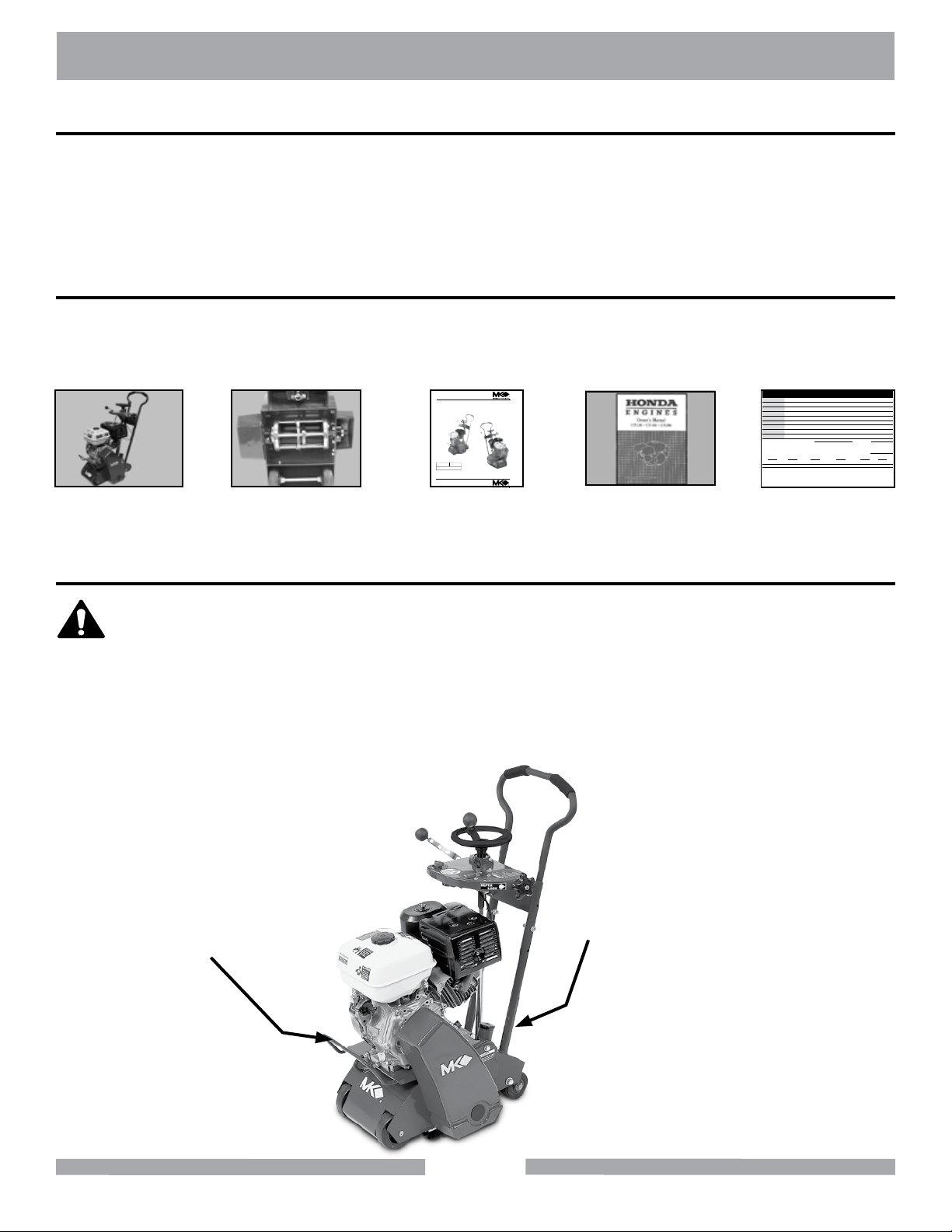
TRANSPORT
1. The Scarier weighs approximately one hundred and eighty-ve (185)
CAUTION
pounds (with the Cutting Drum assembled the scarier weighs approximately
230 pounds), use care when transporting.
2. Two people are required to transport the Scarier.
To lift the scarier, each person will stand on opposite sides of the Scarier and grasp the rear Handlebar and the front Handle/Stand to lift, as shown below.
Handlebar
Lift Point
Handle/
Stand
Lift Point
14
Page 15
MK-SCARIFIER HANDLEBAR ASSEMBLY
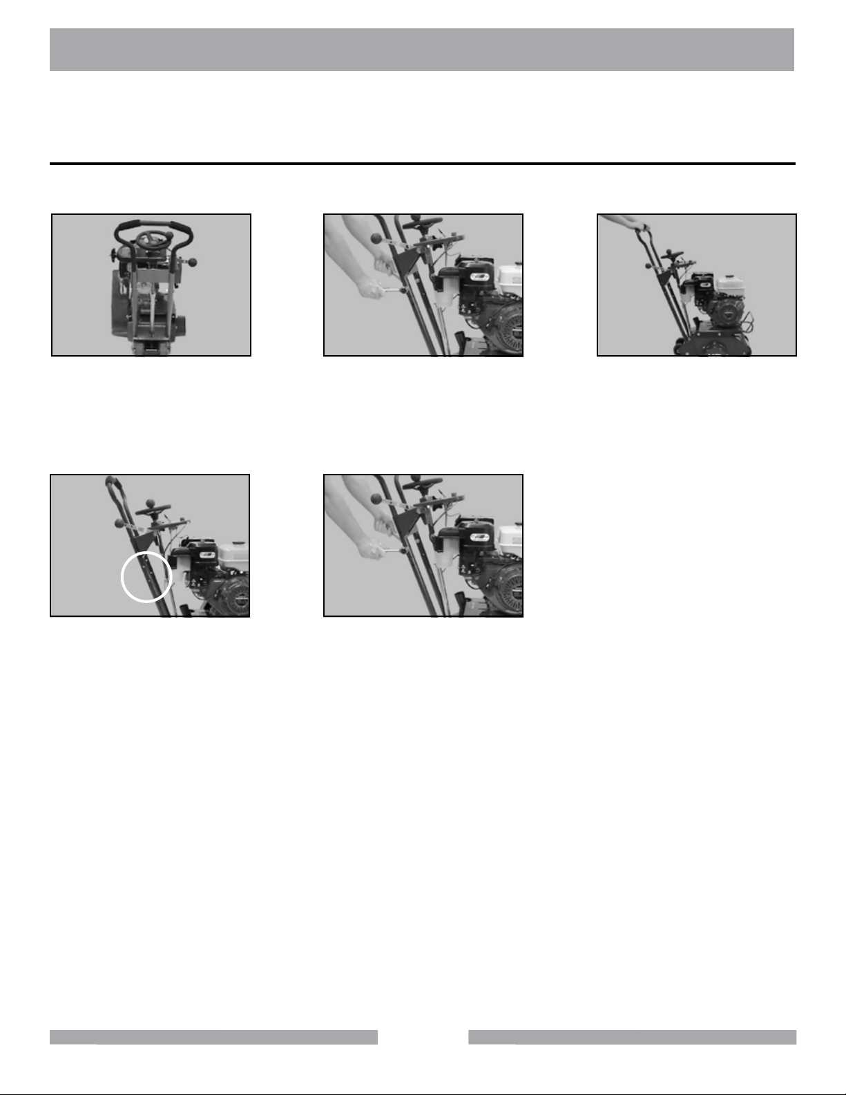
Follow the assembly instructions to prepare your Scarier for operation.
Handlebar Adjustment
Adjust the Handlebar for for ease of operation and comfort of the user.
(A)
Locate the Handlebar retain-
ing bolts.
(D)
Align one set of Retaining
Bolt holes in the Handlebar to
the holes in Scarier Frame.
Remove the Retaining Bolts
using 9/16 wrenches and/or
Install the Retaining Bolts
and tighten using 9/16
wrenches and/or sockets.
(B)
Raise or lower the Handle-
sockets.
(E)
NOTE: Do not rotate saw to rest on handlebar. Engine damage will result.
(C)
bar as needed.
15
Page 16

MK-SCARIFIER SCARIFIER DRUM
ScarierDrumCutters
Five Tooth Carbide Tip Star
• Used for grinding, leveling, grooving, cleaning, and preparing concrete
• Five-point carbide tips (1-3/4” OD x 5/8” ID x 1/4”)
• Longer life than steel tooth cutters, average of 6000 to 8000 square feet
• Maximum cutting rate is 1/8” per pass
Six Tooth Carbide Tip Star
• Used for grinding, leveling, grooving, cleaning, and preparing concrete
• Five-point carbide tips (1-3/4” OD x 5/8” ID x 1/4”)
• Exceptional life, average of 8000 to 10000 square feet
• Maximum cutting rate is 1/8” per pass
18 Tooth Steel Sharp Tooth Cutter
• Used for general cleaning of concrete or asphalt including removal of
paint, epoxy, urethane, adhesive, and heavy dirt, grease and oil deposits
• 18 tooth hardened steel, (2” OD x 5/8” ID x 1/4”)
• Average life of 500 to 800 square feet
• Maximum cutting rate is 1/16” per pass
Part # 158583
Part # 158584
Part # 158585
12 Tooth Steel Blunt Tooth Cutter
• Used for paint and oil removal, trafc and shop oor safety-line removal,
cleaning and concrete preparation
• 12 tooth, hardened steel (2” OD x 9/16” ID x 1/4”)
• Average life of 500 to 800 square feet
• Maximum cutting rate is 1/16” per pass
Hardened Steel Spacer
• Used to ll empty space between the cutting discs
• 1/2” ID hardened steel
16
Part # 158586
Part # 158575
Page 17
MK-SCARIFIER DRUM CONFIGURATIONS
SteelDrumCongurationforRemoval
120 Steel Cutters
246 Spacers (S)
6 Shafts
GeneralPurpose/CleaningDrumConguration
84 Carbide Stars
192 Spacers (S)
6 Shafts
17
Page 18
MK-SCARIFIER DRUM CONFIGURATIONS
1”GrooveDrumConguration
42 Carbide Stars
288 Spacers (S)
6 Shafts
5”Stripe/LineDrumConguration
123 Steel Cutters
231 Spacers (S)
6 Shafts
18
Page 19
MK-SCARIFIER ASSEMBLY
NOTE:
Leveling a Surface
The Height Adjustment Hand-wheel will adjust the depth (up or down) of the Cutting Drum
by 1/16 of an inch per turn.
A) Congure the Cutting Drum for Grooving
B) Locate the lowest spot and highest spot on the surface
C) Adjust the height of the Cutting Drum to remove approximately 1/16 of an inch from the
high spot
D) Set the Vibration Lock
E) Move the Scarier in a smooth forward motion.
F) When the Cutting Discs are no longer contacting the surface, return the Scarier to the
starting position
G) Repeat Steps A through E until the Surface is level (See Figure 1)
Set 1/16 –
inch below
the surface
High Point
Direction of Movement
Cutting/Grooving a Surface
A) Congure the Cutting Drum for Grooving
B) Adjust the Cutting Drum Depth until the Scarier is cutting grooves approximately 1/8 of
an inch
C) Move the Scarier in a smooth forward motion
D) Should the Cutting Discs loose contact with the surface, repeat Step B and continue
forward motion
E) Repeat Steps A through D until the desired number of grooves are cut (See Figure 2)
Set 1/8 – inch
below the
surface
Figure 1
Maintain
set cutting
depth
Direction of Movement
Figure 2
19
Page 20
MK-SCARIFIER ASSEMBLY
Roughening or Preparing a Surface
A) Congure the Cutting Drum for Surface Prep.
B) Adjust the Cutting Drum Depth until the Cutting Discs are contacting the surface (increase
the depth of the Cutting Drum as necessary to increase the “roughness of the surface”
C) Scarier in a smooth forward motion
D) Should the Cutting Discs loose contact with the surface, repeat Step B and continue for-
ward motion
E) Repeat Steps A through D until the desired roughness is achieved. (See Figure 3)
Set depth to
contact the
surface
Direction of Movement
Maintain
set cutting
depth
Figure 3
20
Page 21
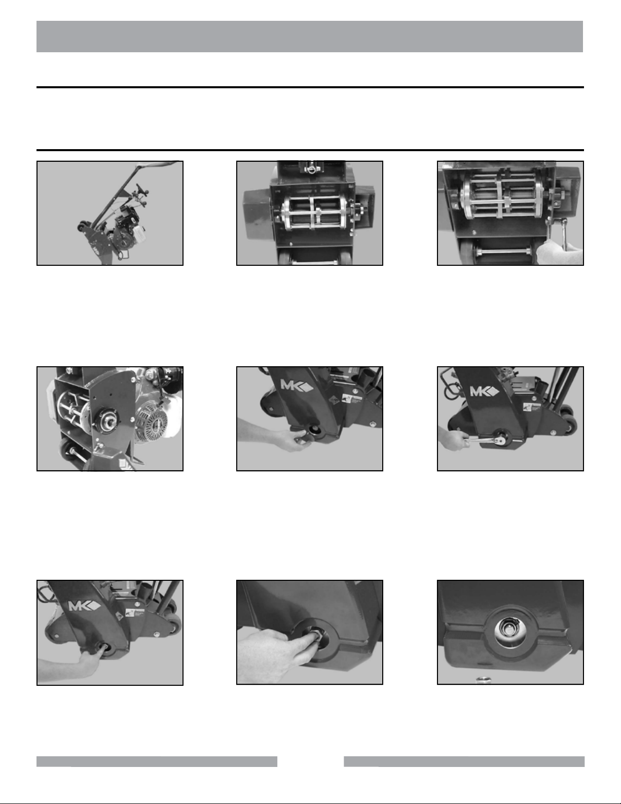
MK-SCARIFIER ASSEMBLY
CUTTING DRUM ASSEMBLY
Because the Cutting Drum assembly is a complex process, the assembly procedure will be broken
into several parts.
Cutting Drum Removal
(A)
Rotate the Scarier to rest on
the Handle/Stand. Never rest
on back handle bar.
(D)
Pivot the Shaft Cover to
expose the end of the Cutting
Drum Shaft.
(B)
Locate the Shaft Cover, Re-
taining Bolts.
(E)
Remove the Shaft, Retaining Nut Cover from the Belt
Guard to expose the Shaft,
Retaining Nuts.
(C)
Remove the Shaft Cover,
Rear Retaining Bolt and
loosen the Front Retaining
Bolt using 9/16 wrenches
and/or sockets.
(F)
Rotate counterclockwise to
using a 15/16-inch socket,
loosen the Outer Shaft, Re-
taining Nut.
(G)
Place an index nger on the
end of the Cutting Drum,
Shaft
Remove the Outer Shaft, Retaining Nut using your middle
nger as shown
(H)
21
(I)
Repeat Step H for the Inner
Shaft, Retaining Nut
Page 22

MK-SCARIFIER ASSEMBLY
(J)
Grasp the Cutting Drum
as shown.
(M)
Remove the Cutting Drum
and Shaft.
(K)
Push the Cutting Drum away
from the belt side to loosen
the Shaft.
Place a rod in the hole on the
end of the Shaft, and while
holding the Cutting Drum,
remove the Shaft.
NOTE: Assembly is opposite of disassembly
(L)
22
Page 23

MK-SCARIFIER ASSEMBLY
CUTTING DRUM DISASSEMBLY
The Cutting Drum may be disassembled from either end.NOTE:
(A)
Rotate the Cutting Drum onto
either end and locate the
Retaining Ring, Retaining
Screws.
(D)
If present, remove the three
Flat Washer Spacers.
(B)
Remove the 3 Retaining
Screws using a 7/16-inch
wrench.
(E)
Place the Retaining Ring and
Flat Washer Spacers in a
secure location.
(C)
Remove the Drum Retaining
Ring.
23
Page 24

MK-SCARIFIER ASSEMBLY
CUTTING DRUM ASSEMBLY
The Cutting Drum may be disassembled from either end.NOTE:
(A)
Pull the Cutting Disc Shafts
out the open side of the Cut-
ting Drum as shown.
(D)
Place the Cutting Drum on
the closed end, with the open
end facing upward.
(B)
Assemble the Cutting Drum
using Cutting Discs and Disc
Spacers (See Cutting Drum
Conguration).
(E)
Obtain the Retaining Ring
and Flat Washer Spacers.
(C)
Continue with Step B until
the Cutting Drum assembly is
complete.
(F)
Install the 3 Flat Washer
Spacers (if used) over the
3 Retaining Ring, Retaining
Screw holes.
(G)
Place the Retaining Ring
onto the end of the Cutting
Drum, aligning the Retaining
Screw Holes.
Install the 3 Retaining Screws
into the Cutting Drum (do not
cross-thread the screws).
(H)
24
(I)
Tighten the 3 Retaining
Screws using a 7/16-inch
wrench.
Page 25

MK-SCARIFIER ASSEMBLY
CUTTING DRUM INSTALLATION
The Cutting Drum may be disassembled from either end.NOTE:
(A)
Install the Cutting Drum; align
the Cutting Drum with the
Shaft-side Bearing and install
the Cutting Drum, Shaft.
(D)
Using a 15/16-inch socket
tighten the Shaft, Inner
Retaining Nut, counterclock-
wise.
(B)
Verify the Cutting Drum and
Shaft are fully installed and
seated.
(E)
Obtain the Shaft, Outer
Retaining Nut.
(C)
Install the Shaft, Inner Re-
taining Nut.
(F)
Install the Shaft, Outer
Retaining Nut.
(G)
Using a 15/16-inch socket
tighten the Shaft, Outer
Retaining Nut.
Install the Shaft, Retaining Nut
Cover onto the Belt Guard.
(H)
(I)
Pivot the Shaft Guard Cover
into position and install the
Rear Retaining Bolt.
FILLING OIL RESERVOIR
NOTE:
SAE 10W-30 is recommended for general use in temperatures of – 4ºF (20ºC) and above.
Engine Oil Capacity is 1.16 US qt (1.1l). Refer to Engine Manual for details.
25
Page 26

MK-SCARIFIER ASSEMBLY
FILLING FUEL TANK
WARNING
1. Gasoline is highly ammable and explosive. You can be burned or seriously
injured when handling fuel.
2. To fuel, stop engine if running, and allow it to cool.
3. Refuel in a well-ventilated area.
4. Keep gasoline away from appliance pilot lights, barbecues, electric
appliances, power tools, etc.
5. Wipe up spills immediately.
NOTES:
1. Fuel can damage paint and plastic. Be careful not to spill fuel when lling the fuel
tank. Damage caused by spilled fuel IS NOT covered under the warranty.
2. DO NOT use stale or contaminated gasoline, or an oil/gasoline mixture.
3. Use unleaded gasoline with a pump octane rating of 86 or higher.
NOTE:
Refer to Engine Manual for details.
VACUUM SETUP FOR OPERATION
The Scarier is designed for use with a vacuum. MK Diamond recommends using a vacuum to reduce the amount of dust generated during operation.
MK Diamond does not endorse any specic vacuum type, but does recommend the customer use the
Scarier with a dry dust collector (designed for wood dust) as opposed to a standard wet/dry vacuum.
(A)
Obtain a vacuum or dust
collection system.
Verify the hose connections
are secure at the Scarier
and the Vacuum.
(D)
Remove the Cap from the
Vacuum Connection Point.
(B)
Using a 2 1/2-inch hose,
connect the Vacuum to the
Scarier at the Vacuum
Connection Point.
26
(C)
Page 27

MK-SCARIFIER SETUP
Pre-start Inspection
The pre-start inspection should be performed before beginning any job. If Cutting Discs are worn, or
are missing carbide inserts (carbide cutting discs only), replace the discs before starting work.
NOTE:
• DO NOT rotate Scarier to rest on handlebar. Engine damage will result.
• The carbide tips on carbide cutting discs are approximately 1/4-inch in length. When
the carbide disc is worn to the end of the carbide tip, the tip may fall out leaving a small
hole.
(A)
Inspect the Cutting Discs for
excessive wear and missing
tips.
(B)
Inspect Engine for leaks.
(C)
Inspect the Scarier for
general damage and/or loose
hardware.
(D)
Verify the Height Adjust-
ing Wheel moves freely
and moves up and down
smoothly.
(G)
Check for proper fuel level
(See Engine Manual).
Verify the Scarier rolls freely.
Check Air Filter for cleanliness
(See Engine Manual).
(E)
(H)
27
(F)
Check for proper oil level
(See Engine Manual).
Page 28

MK-SCARIFIER SETUP
STARTUP
WARNING
1. Carbon monoxide gas is toxic, breathing it can cause unconsciousness and/
or death.
2. Avoid any areas or actions that expose you to carbon monoxide.
NOTE:
Verify the Engage/Disengage
Lever is in the “Lift” position.
If restarting a warm engine, leave the Choke Lever in the OPEN position.
(A)
(B)
Raise the Cutting Drum to the
highest position.
(C)
Place Fuel Valve in the
ON position.
(D)
Place Choke Lever in the
CLOSED position.
(G)
Pull Starter Cord slowly, until
slack is removed and
resistance is felt.
Move the Throttle Lever to
Pull Starter Cord straight
back in a smooth
(E)
1/3rd open.
(H)
fast motion.
28
(F)
Place Engine Switch in the
ON position.
(I)
Place Choke Lever in the
OPEN position when engine
is warm.
Page 29

MK-SCARIFIER SETUP
STARTUP
The Scarier is capable of performing several different operations simply by changing drum conguration. The following steps describe how it is operated in any conguration.
(A)
Start the Scarier in accor-
dance with Engine Start, Step
1 of the STARTUP section,
page 24.
(D)
Adjust the height of the Cut-
ting Drum for the Job being
performed (See Basic Grind-
ing Techniques).
(B)
Raise the Cutting Drum to the
highest position.
(E)
Locate the Vibration Lock.
(C)
Place the Engage/Disengage
Lever in the “Lower” position.
(F)
Lock the height of the drum
using the Vibration Lock.
When turning the Scarier, lift the Rear Wheels off the ground, and pivot the it on the Front Wheels.
NOTE:
(G)
Adjust the speed
by using the Throttle,
as desired.
Push the Scarier at a
smooth, even pace to per-
(H)
form the cut.
29
(I)
Place the Engage/Disengage
Lever in the “Lift” when the
cut is complete.
Page 30

MK-SCARIFIER OPERATION
Normal Engine Shutdown
(A)
Verify the Engage/Disengage
Lever is in the “Lift” position.
(D)
Place Engine Master Switch
in the OFF position.
(B)
Raise the Cutting Drum to the
highest position.
(E)
Place Fuel Valve in
the OFF position.
(C)
Move the Throttle Lever to
lower blade speed.
30
Page 31

MK-SCARIFIER OPERATION
Emergency Engine Shutdown
(A)
Place Engine Master Switch
in the OFF position.
(D)
Verify the Engage/Disengage
Lever is in the “Lift” position.
(B)
Move the Throttle Lever to
lower blade speed.
(E)
Raise the Cutting Drum to the
highest position.
Place Fuel Valve in the
(C)
OFF position.
CLEANUP
Engine parts are extremely hot following use, allow engine to cool 1/2-hour before cleaning. Use care
during cleanup to avoid injury.
NOTES:
1. To extend operating life, the scarier should be cleaned following every use.
2. Using a garden hose or pressure washer can force water into the air cleaner or
mufer opening.
3. Use care when cleaning around electrical components.
(A)
Clean the Scarier with soap
and water.
Verify the engine is off and cool
before beginning to clean.
(B)
31
(C)
Clean around the Depth Con-
trol Wheel bearing.
Page 32

MK-SCARIFIER CLEANUP
(D)
Clean the Depth
Control Screw.
(G)
Remove the Cutting Drum
(See Setup Section).
Clean the remainder of the
exterior surface of the scari-
er (except the engine).
Clean the Shaft Penetration
Hole of the Cutting Drum.
(E)
(H)
New Maintenance
Perform the following after initial purchase and operation of the saw.
(F)
Clean engine throttle linkage
with a dry cloth.
(I)
Clean the Cutting Drum,
Shaft.
(A)
Change engine oil after 1st
month or 1st 20 operating
hours (See Engine Manual).
Check and adjust tension on
all V-belts following 1st 48
hours of operation (See V-
belt Inspection).
(B)
32
Page 33

MK-SCARIFIER MAINTENANCE
Maintenance Following Use
The following maintenance should be performed following each use. Use Light oil, such as WD-40 or
3 in 1 when lubricating parts.
NOTES:
Due to the material used in the Cutting Drum and Shaft, it is critical that Steps C and D
be performed.
(A)
Shutdown the Engine (See
Normal Engine Shutdown).
(B)
Check Air Filter for cleanliness
(See Engine Manual).
(C)
Lubricate arbor in drum.
Clean engine throttle linkage
with a dry cloth.
(D)
Lubricate the Cutting Drum
Shaft.
(G)
Lubricate the Front Wheel
Assembly.
Reinstall the Cutting Drum.
Lubricate the Rear Wheel
(E)
(H)
Assembly.
33
(F)
Lubricate the outer surface of
the Cutting Drum.
(I)
Lubricate the Engage/ Disen-
gage Pivot Shaft.
Page 34

MK-SCARIFIER MAINTENANCE
(J)
Lubricate and clean the
Depth Control Screw.
Lubricate engine Throttle
(K)
Linkage.
Monthly Maintenance
The following should be performed monthly. Items should be lubricated using a waterproof grease.
(A)
Verify the tightness of all bolts
and screws.
Lubricate the Height Adjusting
Wheel Bearing.
(B)
(C)
Lubricate the Depth Control
Screw.
(D)
Lubricate the Cutting Drum,
Shaft Bearings.
Lubricate the Front Wheel
Assembly Bearings.
(E)
34
(F)
Clean engine Air Filter (See En-
gine Air Filter Inspection Cleaning
and Replacement).
Page 35

MK-SCARIFIER MAINTENANCE
Six (6) Month Maintenance
Perform the following maintenance every six months.
(A)
Change engine oil
(See Engine Manual).
Clean Fuel Sediment Cup
(See Fuel Sediment Cup
Yearly and Two-Year Maintenance
Perform the following maintenance every year.
(A)
Replace engine Air Filter
(See Engine Manual).
Replace Spark Plug
(See Engine Manual).
(B)
Cleaning).
(B)
(C)
Clean and Readjust engine
Spark Plug
(See Engine Manual).
(C)
Inspect V-belts
(See V-Belt Inspection, Adjust-
ment and Replacement).
(D)
Check/Adjust Idle Speed
Check/Adjust Valve Clear-
ance (Shop Maintenance
Required).
Check Fuel Line (2-Year
Maintenance Only, Shop
Maintenance Required).
(E)
35
Page 36

MK-SCARIFIER MAINTENANCE
Check Fuel Level
WARNING
NOTES: 1. Fuel can damage paint and plastic. Be careful not to spill fuel when lling the fuel tank.
Damage caused by spilled fuel is not covered under the warranty.
2. DO NOT use stale or contaminated gasoline or an oil/gasoline mixture.
3. Use unleaded gasoline with a pump octane rating of 86 or higher.
NOTE:
Checking Oil Level
NOTES: 1. Engine Oil Capacity is 1.16 US qt (1.1 l).
2. When installing the Oil Dipstick, ensure the threads are aligned with the threads of the
Refer to Engine Manual for details.
Oil Reservoir so as not to “cross-thread.”
1. Gasoline is highly ammable and explosive. You can be burned or seriously
injured when handling fuel.
2. To fuel, stop engine if running and allow it to cool.
3. Refuel in a well-ventilated area.
4. Keep gasoline away from appliance pilot lights, barbecues, electric appliances,
power tools, etc.
5. Wipe up spills immediately.
NOTE:
Refer to Engine Manual for details.
36
Page 37

MK-SCARIFIER MAINTENANCE
100ºF
-20ºF
0ºF
20ºF
40ºF
60ºF
80ºF
10W-30
5W-30
30
-20ºC
-10ºC
0ºC
10ºC
20ºC
30ºC
40ºC
-30ºC
Changing Oil
Oil is a major factor affecting performance and service life. Use 4-stroke automotive detergent oil.
Refer to Engine Manual for specic procedures. SAE 10W-30 is recommended for general use. Other
viscosity oil shown in the chart below may be used when the average temperature in your area is
within the recommended range.
NOTES:
1. Drain used oil while the engine is warm.
2. Conform to Federal, State and Local laws, codes and ordinances relative to
environmental protection for oil disposal.
NOTE: Refer to Engine Manual for details.
(A)
Lower the Scarier to its low-
est position.
Free the Oil Drain Line.
(B)
(C)
Place a catch basin below
the Oil Drain Line and re-
move the Drain Cap using
two 1/2 –inch wrenches.
(D)
Drain Oil the engine oil (con-
form to Federal, State and
Local laws for disposal).
(E)
Using two 1/2 – inch
wrenches, install the Drain
Cap onto the Oil Drain Line
(Ensure the Cap is tight).
37
(F)
Fill the Oil Reservoir
(See Engine Manual).
Page 38

MK-SCARIFIER MAINTENANCE
Fuel Sediment Cup Cleaning
WARNING
NOTES:
1. Conform to Federal, State and Local laws for the proper disposal of fuel
2. Fuel can damage paint and plastic. Be careful not to spill fuel when lling the fuel
tank. Damage caused by spilled fuel IS NOT covered under the warranty.
3. DO NOT use stale or contaminated gasoline or an oil/gasoline mixture.
4. When installing the Sediment Cup retaining bolt, ensure the threads of the bolt are
aligned with the threads on the Fuel Valve so as not to “cross-thread the nut.”
1. Gasoline is highly ammable and explosive. You can be burned or seriously
injured when handling fuel.
2. To fuel, stop engine if running and allow it to cool.
3. Refuel in a well-ventilated area
4. Keep gasoline away from appliance pilot lights, barbecues, electric
appliances, power tools, etc.
5. Wipe up spills immediately.
(A)
Place Fuel Valve in the OFF
position.
Loosen the Fuel
Sediment Cup. (See Engine
Manual for details)
(B)
Spark Plug Adjustment and Replacement
CAUTION
NOTES:
DO NOT work around the engine while hot.
1. When installing the Spark Plug, ensure the threads of the plug are aligned
with the threads in the engine so as not to “cross-thread” the plug.
2. See Engine Manual for specic details.
38
Page 39

MK-SCARIFIER MAINTENANCE
Engine Air Filter Inspection Cleaning and Replacement
Refer to Engine Manual.
Cutting Drum Change-out
WARNING
NOTE:
(A)
Remove the Shaft Cover,
Rear Retaining Bolt and
loosen the Front Retaining
Bolt using 9/16 wrenches
and/or sockets.
blades, bits, cutters, and the like.
DO NOT Rotate saw to rest on handlebar. Engine damage will result.
Disconnect the tool before servicing and when changing accessories, such as
(B)
Remove the Shaft, Retaining Nut Cover from the Belt
Guard to expose the Shaft,
Retaining Nuts.
(C)
Using a 15/16-inch socket,
loosen the Outer Shaft, Re-
taining Nut. Retaining Nuts are
left hand threaded.
(D)
Place an Index Finger on the
end of the Cutting Drum, Shaft.
(G)
Remove the Cutting
Drum and Shaft.
Remove the Outer Shaft, Retaining Nut using your Middle
Finger as shown.
Recongure the Cutting
Drum as needed.
(E)
(H)
39
(F)
Repeat Step C through E for
the Inner Shaft, Retaining Nut.
(I)
Install the Cutting Drum into the
Scarier; align the Cutting Drum
with the Shaft-side Bearing and
install the Cutting Drum, Shaft.
Page 40

MK-SCARIFIER MAINTENANCE
(J)
Verify the Cutting Drum and
Shaft are fully installed and
seated.
(M)
Obtain the Shaft, Outer
Retaining Nut.
(K)
Install the Shaft, Inner Re-
taining Nut.
(N)
Install the Shaft, Outer
Retaining Nut.
(L)
Using a 15/16-inch socket
tighten the Shaft, Inner
Retaining Nut.
(O)
Using a 15/16-inch socket
tighten the Shaft, Outer
Retaining Nut.
(P)
Install the Shaft, Retaining
Nut Cover onto the
Belt Guard.
Pivot the Shaft Guard Cover
into position and install the
Rear Retaining Bolt.
(Q)
(R)
Tighten the Shaft Guard Cover
Retaining Bolts using 9/16
wrenches and/or sockets.
40
Page 41

MK-SCARIFIER MAINTENANCE
ReconguretheCuttingDrum
(A)
Remove the Cutting
Drum (See Cutting Drum
Change-out).
(D)
If present, remove the three
Flat Washer Spacers.
(B)
Place the Cutting Drum
on end and remove the 3
Retaining Screws using a
7/16-inch wrench.
(E)
Place the Retaining Ring and
the 3 Flat Washer Spacers in
a secure location.
(C)
Remove the Retaining Ring
from the Cutting Drum.
(F)
Pull the Cutting Disc Shafts
and remove the Cutting Discs
and Disc Spacers.
(G)
Assemble the Cutting Drum
using Cutting Discs and Disc
Spacers (See Cutting Drum
Conguration).
Continue with Step B
until the Cutting Drum as-
sembly is complete.
(H)
41
(I)
Place the Cutting Drum on
the closed end, with the open
end facing upward.
Page 42

MK-SCARIFIER MAINTENANCE
(J)
Obtain the Retaining Ring
and Flat Washer Spacers.
(M)
Install the 3 Retaining Screws
into the Cutting Drum (do not
cross-thread the screws).
(K)
Install the 3 Flat Washer
Spacers (if used) over the
3 Retaining Ring, Retaining
Screw holes.
(N)
Tighten the 3 Retaining
Screws using a 7/16-inch
wrench.
(L)
Place the Retaining Ring
onto the end of the Cutting
Drum, aligning the Retaining
Screw Holes.
(O)
Install the Cutting Drum
(See Cutting Drum Change-
out).
42
Page 43

MK-SCARIFIER MAINTENANCE
Dust Screen Brush Change Out
NOTE: The four (4) Brushes should be replaced at the same time (MK Diamond Part # 160300).
(A)
Inspect the Dust Screen
Brushes for wear.
(D)
Obtain Replacement
Brushes.
(B)
Loosen the end of each
Brush Holder with a Flat
Blade Screwdriver.
(E)
Slide the new Brushes into
the Brush Holders.
(C)
Slide each Brush out of its
Brush Holder.
(F)
Pinch the end of the Brush
Holders to hold each Brush in
place.
43
Page 44

MK-SCARIFIER MAINTENANCE
Front Wheel Change Out
NOTE: The two (2) Front Wheels should be replaced at the same time (MK Diamond Part # 138529).
(A)
Rotate the Scarier to rest on
the Handle/Stand.
(D)
Obtain 2 replacement Wheels
and remove the Dust Cover
from one side of each Wheel.
(B)
Loosen the Retaining Collar
of each Wheel using a 5/32-
inch Allen Wrench.
(E)
Seat the Front Wheels into
the Wheel-well with the Dust
Cover side
facing inward.
(C)
Move the Retaining Collars
toward the center of the Axle
and then slide the Axle out of
the Scarier.
(F)
Slide the Axle through one
Wheel, Install the 2 Retain-
ing Collars and then slide
the Axle through the second
Wheel.
(G)
Push the Retaining Collars
against the Front Wheels
and then tighten them with a
5/32-inch Allen Wrench.
44
Page 45

MK-SCARIFIER MAINTENANCE
Rear Wheel Change Out
NOTE: The two (2) Rear Wheels should be replaced at the same time (MK Diamond Part # 158520).
(A)
Rotate to rest on the Handle/
Stand.
(D)
Remove the Rear
Wheel Truck Assembly Re-
taining Bolts.
(B)
Locate the Rear Wheel
Truck Assembly.
(E)
Lower the Rear Wheel Truck
Assembly.
(C)
Remove the Rear Wheel
Truck Assembly Retain-
ing Nuts using 3/4-inch
wrenches.
(F)
Remove the Rear Wheel
Retaining Cotter Pin, Shim
Washer and Rear Wheel from
each side of the Assembly.
(G)
Obtain replacement wheels.
Install the new Rear Wheel,
Shim Washer and Cotter Pin
on each side of the Assem-
(H)
bly.
45
(I)
Install the Rear Wheel Truck
Assembly Retaining Nuts and
Bolts removed in Steps C
and D using
3/4-inch wrenches.
Page 46

MK-SCARIFIER MAINTENANCE
V-Belt Inspection, Adjustment and Replacement
In order to ensure the Scarier operates at peak efciency, the power transmission V-belt should be
inspected monthly and changed if any signs of damage and/or excessive wear is observed.
NOTE: When a new belt is installed, it should be inspected and re-tensioned after the rst forty-eight
(48) hours of operation.
(A)
Remove the Cutting
Drum (See Cutting Drum
Change-out).
(D)
Inspect the V-belt for exces-
sive wear, cracks and cuts –
if worn, proceed to step F.
(B)
Locate and remove the Belt
Guard Retaining Screws us-
ing a 9/16-wrench.
(E)
Check V-belt for proper ten-
sion, if tension correct, go to
step O (proper tension is 1/2-
inch deection of the belt).
(C)
Remove the Belt Guard.
(F)
Locate the Engine Mounting
Plate Bolts on both sides.
(G)
Loosen the Front Engine
Mounting Plate Bolts on
both sides using a 9/16-inch
wrench.
Loosen the Rear Engine
Mounting Plate Bolts on
both sides using a 9/16-inch
(H)
wrench.
46
(I)
Locate the V-belt Adjusting
Screw Lock Nut inside
the Cutting Drum Well.
Loosen the nut using a
9/16-inch wrench.
Page 47

MK-SCARIFIER MAINTENANCE
(J)
Locate the V-belt Adjust-
ing Screw inside the Cut-
ting Drum Well. Loosen the
screw using a 9/16-inch
wrench.
(M)
Obtain and install a new
V-belt onto the Engine and
Cutting Drum Pulleys.
(K)
Remove the V-belt from the
Engine and Cutting Drum
Pulleys.
(N)
Verify the V-belt is seated in
all grooves of the Engine and
Cutting Drum Pulleys.
(L)
Clean and verify the align-
ment of the Engine and Cut-
ting Drum Pulleys.
(O)
Pull the front of the Engine
Mounting Plate away from
the Frame to tension the
V-belt.
(P)
Tighten the V-belt Adjust-
ing Screw one turn using a
9/16-inch wrench.
Verify the tension of the
V-belt (proper tension is
1/2-inch deection of
(Q)
the belt).
47
(R)
Repeat Steps P and Q until
proper tension has been
reached (proper tension is
1/2-inch deection of the
belt).
Page 48

MK-SCARIFIER MAINTENANCE
(S)
Tighten the V-belt Adjust-
ing Screw Lock Nut using a
9/16-inch wrench.
(V)
Tighten the Belt
Guard Retaining Screws us-
ing a 9/16-wrench.
(T)
Tighten the Engine Mounting
Plate Bolts on both sides us-
ing a 9/16-inch wrench.
(W)
Install the Cutting Drum; (See
Cutting Drum Change-out).
(U)
Install the Belt Guard.
48
Page 49

NOTES
49
Page 50

MK-SCARIFIER EXPLODED VIEW
50
Page 51

MK-SCARIFIER EXPLODED VIEW
51
Page 52

MK-SCARIFIER PARTS LIST
ITEM DESCRIPTION PART# QTY.
A ASSEMBLY, ACCESSORIES n/a -
A1 PALLET, SHIPPING (NOT SHOWN) 158535 1
A2 CARTON, MK SCARIFIER SHIPPING (NOT SHOWN) 158536 1
A3 CARTON, SCARIFIER DRUM (NOT SHOWN) 158825 1
A4 MANUAL, OWNER’S (NOT SHOWN) 158537 1
A5 TUBE, OWNER’S MANUAL (NOT SHOWN) 155419 1
A6 (REFERENCE ONLY) SPACER, HARDEN STEEL 158575 A7 (REFERENCE ONLY) STAR, 5 POINT CARBIDE TIP (1 ¾ OD X 5/8” ID) 158492 A8 (REFERENCE ONLY) STAR, 6 POINT CARBIDE TIP (1 ¾ OD X 5/8”ID) 158493 A9 (REFERENCE ONLY) CUTTER, 18 SHARP TOOTH STEEL (2” OD X 9/16”ID) 158494 -
A10 (REFERENCE ONLY) CUTTER, 12 BLUNT TOOTH STEEL (2” OD X 5/8”ID) 158495 -
B ASSEMBLY, FRAME 158609 -
B1
BA1
B2 PLATE, SERIAL NUMBER 157458 1
B3 #7 X 5/16 DRIVE SCREW 227214 4
B4 CAP, 2”OD VINYL 158914 1
B5 LABEL, 1 ¾ X 5” MK LOGO 154335 1
B6 LABEL, CAUTION, HANDS AND FEET 155585 1
B7 LABEL, CAUTION, DO NOT OPERATE WITH GUARDS REMOVED 155587 1
FRAME WELDMENT (MK RED)
FRAME WELDMENT (ORANGE)
158098
158098-OR
1
1
C ASSEMBLY, FRAME DUST SCREEN n/a -
C1 SCREEN, RIGHT SIDE, FRAME DUST 158594 1
C2 SCREEN, LEFT SIDE, FRAME DUST 158595 1
C3 SCREEN, FRONT / BACK, FRAME DUST 158596 2
C4 SCREW, 1/4-20 X 1/2 PAN HEAD PHILLIPS CAP 155452 4
C5 SCREW, 1/4-20 X 1/2 FLAT HEAD PHILLIPS CAP 155812 4
C6 NUT, 1/4-20 KEPS 153941 8
C7 WASHER, 1/4 SAE FLAT 151915 8
D ASSEMBLY, FRONT AXLE n/a -
D1 WHEEL, FRONT, 5 DIA. X 2 138537 2
D2 COLLAR, 3/4 SET 153814 2
D3 AXLE, 3/4 DIA. FRONT 158522 1
E ASSEMBLY, TRUCK n/a 1
E1 TRUCK, WELDMENT 158099 1
E2 WASHER, 3/4 SHIM 153699 ~
E3 WHEEL, 4 DIA. X 2 158520 2
E4 PIN, COTTER, 1/8 X 1 ½ 153861 2
E5 BOLT, 1/2-13 X 4 HEX HEAD TAP 156626 2
E6 WASHER, 1/2 SAE FLAT 150924 4
E7 NUT, 1/2-13 TOP LOCK, HEX 153943 2
52
Page 53

MK-SCARIFIER PARTS LIST
ITEM DESCRIPTION PART# QTY.
F ASSEMBLY, CONSOLE n/a -
F1
FA1
F2 LABEL, CONTROL 158287 1
F3 LABEL, DEPTH LOCK 155577 1
G ASSEMBLY, STANDARD WIRE HARNESS N/A 1
G WIRE HARNESS, STANDARD, HONDA 158232 1
G SWITCH, ENGINE ON/OFF 157851 1
H ASSEMBLY, THROTTLE HONDA - -
H1 SCREW, 10-24 X 1/2 PAN HEAD PHILLIPS CAP 151744 2
H2 NUT, 10-24 CLIP 155407 2
H3 ASSEMBLY, THROTTLE HEAD 155406 1
H4 CABLE, THROTTLE, HONDA 154158 1
J ASSEMBLY, DEPTH CONTROL - -
- SUBASSEMBLY, DEPTH CONTROL WHEEL 155457 1
J1 WHEEL, DEPTH CONTROL 158574 1
J2 SCREW, 3/8-16 X 1/2 SOCKET HEAD SET 153710 1
J3 KNOB, 1” BALL 158519 1
J4 SCREW, 1/2 X 3/4 SOCKET HEAD SHOULDER, W/ 3/8-16 X 5/8 THREAD 156177 1
- SUBASSEMBLY, DEPTH CONTROL TUBE 155460 1
J5 TUBE, DEPTH CONTROL 155049 1
J6 NUT, 3/8-16 NYLOCK HEX 152505 1
J7 SCREW, 3/8-16 X 2 HEX HEAD CAP 153485 1
J8 BEARING, FLANGE, W/ ZERK FITTING 155151 1
J9 SCREW, 3/8-16 X 1 1/4 HEX HEAD CAP 150774 2
J10 WASHER, 3/8 SAE FLAT 150923 1
J11 NUT, 3/8-16 NYLOCK HEX 152505 2
J12 SPACER, 1.5” DEPTH CONTROL 155161 1
J13 SCREW, 15” DEPTH CONTROL 158521 1
WELDMENT, CONSOLE (MK RED)
WELDMENT, CONSOLE (ORANGE)
158100
158100-OR
1
1
K ASSEMBLY, DEPTH LOCK N/A -
K1 LOCK, 8-7/8 DEPTH CONTROL 157846 1
K2 KNOB, DEPTH LOCK 155845 1
K3 THRUST WASHER 155238 1
K4 NUT, 3/8-16 NYLOCK HEX 152505 1
L ASSEMBLY, QUICK LIFT AND LOWERING LEVER N/A -
L1 LEVER 158102 1
L2 KNOB, 2” BALL 158519 1
L3 SCREW, 3/8-24 X 1 HEX HEAD CAP 157803 1
L4 WASHER, 3/8 SAE FLAT 150923 1
L5 WASHER, 3/8 SPLIT LOCK 150925 1
L6 PIVOT, SHAFT 158288 1
53
Page 54

MK-SCARIFIER PARTS LIST
ITEM DESCRIPTION PART# QTY.
L7 SCREW, 1/2-13 X 1 1/4 HEX HEAD CAP 153532 1
L8 WASHER, 1/2 SPLIT LOCK 153524 1
L9 WASHER, 1/2 SAE FLAT 150924 1
M ASSEMBLY, ENGINE MOUNT N/A -
M1
MA1
M2 BOLT, 3/8-16 X 1 HEX HEAD CAP 152507 4
M3 WASHER, 3/8 SAE FLAT 150923 9
M4 WASHER, 3/8 SPLIT LOCK 150925 3
M5 NUT, 3/8-16 NYLOCK HEX 152505 2
M6 NUT, 3/8-16 HEX 101188 3
M7 BOLT, 3/8-16 X 3 HEX HEAD TAP 155830 1
M8 LABEL, CAUTION, BELT TENSION 155583 1
M9 LABEL, CAUTION, SPARKPLUG 155579 1
N ASSEMBLY, ENGINE, 9HP HONDA 155396-MK 1
N1 ENGINE, HONDA GX240 9 HP W/ CYCLONE FILTER 155396 1
N2 DEFLECTOR, HONDA 155375 1
N3 SCREW, 6-32 X 3/8 PAN HEAD PHILLIPS SELF-TAPPING CAP 153466 3
N4 PULLEY, 2 ½”OD, POLY-V 158470 1
N5 POLLY-V-BELT (350J16) 158469 1
N6 NUT, 3/8-16 HEX 101188 4
N7 WASHER, 3/8 SPLIT LOCK 150925 4
N8 WASHER, 3/8 SAE FLAT 150923 8
N9 SCREW, 3/8-16 X 2 HEX HEAD CAP 153485 4
N10 PIN, THROTTLE CONTROL 151284 1
N11 SCREW, 8-32 X 1/2 PAN HEAD PHILLIPS CAP 152517 1
N12 PIN, COTTER, 1/16 X ¾ 152518 1
N13 PLUG, ¾ FLUSH HEAD BUTTON 156615 1
N14 OIL DRAIN, M12 X 3/8 PUSH 157577-02 1
N15 LABEL, CAUTION, HOT SURFACE, 1.5 X 3.0 155578 1
N16 LABEL, WARNING, REFUELING, 1.5 X 3.0 155580 1
N17 LABEL, DANGER, CALIFORNIA, 1.5 X 3.0 155581 1
N18 LABEL, DANGER, LETHAL EXHAUST, 1.5 X 3.0 155582 1
ENGINE, MOUNT (MK RED)
ENGINE, MOUNT (ORANGE)
158101
158101-OR
1
1
P ASSEMBLY, BELT GUARD N/A -
P1
PA1
P2 SCREW, 3/8-16 X 1 HEX HEAD CAP 152507 3
P3 WASHER, 3/8 SAE FLAT 150923 3
P4 WASHER, 3/8 SPLIT LOCK 150925 3
P5 PLUG, 2” DIA REMOVABLE 158538 1
P6 LABEL, CAUTION, BELT TENSION 155583 1
P7 LABEL, CAUTION, GUARDS IN PLACE 155587 1
GUARD, BELT (MK RED)
GUARD, BELT (ORANGE)
158104
158104-OR
54
1
1
Page 55

MK-SCARIFIER PARTS LIST
ITEM DESCRIPTION PART# QTY.
Q ASSEMBLY, SHAFT GUARD N/A -
Q1
QA1
Q2 SCREW, 3/8-16 X 1 1/4 HEX HEAD CAP 150774 2
Q3 WASHER, 3/8 SAE FLAT 150923 4
Q4 WASHER, 3/8 SPLIT LOCK 150925 2
Q5 NUT, 3/8-16 HEX 101188 2
R ASSEMBLY, DRUM BEARING N/A -
R1 HOUSING, BEARING 158467 2
R2 BEARING 158468 1
R3 BEARING, 1” HEX ID 160834 1
R4 SHAFT, PULLEY 158466 1
R5 SCREW, 3/8-24 X 3/4 SOC HEAD CAP 158496 4
R6 PULLEY, 4.0”OD, POLY-V (16J40 X 1 ¼ BORE) 158472 1
R7 SCREW, 3/8-24 X 1 HEX HEAD CAP 157803 8
R8 WASHER, 3/8 SAE FLAT 150923 8
R9 WASHER, 3/8 SPLIT LOCK 150925 8
GUARD, SHAFT (MK RED)
GUARD, SHAFT (ORANGE)
158581
158581-OR
1
1
S ASSEMBLY, 8” DRUM 158460 1
S1 DRUM, WELDMENT, 8” 158461 1
S2 BUSHING, DRUM (.515 ID) OR (33/64 ID) 158462 18
S3 SHAFT, 8” HARDEN STEEL 158463 6
S4 RING, DRUM RETAINING 158464 2
S5 SCREW, 5/16-18 X ¾ TAP, 151369 6
S6 WASHER, 5/16 SPLIT LOCK 151747 6
S7 WASHER, 5/16 FLAT SAE 151754 6
S8 BUSHING, FLANGED (.515 ID) OR (33/64 ID) 165248 12
T ASSEMBLY, 8” DRUM, DRIVE SHAFT N/A -
T1 SHAFT, 8” DRUM, DRIVE 158465 1
T2 NUT, 5/8-11 HEX JAM (LEFT HAND THREAD) 158577 2
U ASSEMBLY, HANDLEBAR N/A -
U1 HANDLEBAR 158359 1
U2 HANDGRIP 150842 2
U3 SCREW, 3/8-16 X 1 HEX HEAD CAP 156602 2
U4 WASHER, 3/8 SPLIT LOCK 150925 4
U5 WASHER, 3/8 SAE FLAT 150923 4
55
Page 56

MK-SCARIFIER EXPLODED VIEW
MK SG-5PH 220 V NO DRUM PART # 170573
15
9
5
3
2
7
14
1
10
6
8
3
2
5
16
12
4
11
13
ITEM DESCRIPTION PART# QTY.
1 KEY, 1/4 SQR X 1 - 3/4 150796 1
2 WASHER, FLAT, SAE, 3/8 150923 11
3 WASHER, LOCK, SPLIT, 3.8 150925 11
4 WASHER, FLAT, SAE, 1/4 151915 2
5 SCREW, HEX HD CAP, 3.8 - 16 X 1 152507 11
6 WASHER, LOCK, SPLIT, 1/4 152591 2
7 SCREW, 5/16 - 18 X 1/2 SOCKET HEAD SET 152607 4
8 SCREW, HEX HD, TAP, 1/4 - 20 X 1 152676 2
9 MTR, 5PH 230V 1PH 50PZ 152759 1
10 PLATE, MOTOR MOUNT (COMP) 155824 1
11 GUARD, BELT (COMP) 158104 1
12 BELT, 16J350 158469 1
13 PLUG, 2” DIA, REMOVABLE 158538 1
14 PULLEY, 16J25 X 1 - 1/8 BORE 160411 1
15 LABEL, 230V 168652 1
16 MK-SG-II LESS ENGINE 170578 1
56
Page 57

MK-SCARIFIER EXPLODED VIEW
MK SG-II LESS ENGINE PART # 170578
12
22
19
17
9
1
10
2
4
18
21
3
23
14
2
11
13
4
6
5
8
15
4
2
2
16
20
ITEM DESCRIPTION PART# QTY.
1 SCREW, 3/8 - 16 X 1 - 1/4 HEX HEAD CAP 150774 6
2 WASHER, FLAT, SAE 3/8 150923 25
3 WASHER, LOCK, SPLIT, 3/8 150925 15
4 NUT, HEX, NYLK, 3/8 - 16 152505 8
5 WASHER, 1/2 SPLIT LOCK 152524 1
6 SCREW, 1/2 - 13 X 1 - 1/4 HEX HEAD CAP 153532 1
7 NUT, 1/2 - 13 HEX 153943 2
8 LINKAGE, DEPTH FEED 1600/9000 155049 1
9 BEARING, FHSLF 204 - 12G FLANGE 155151 1
10 SPACER, DEPTH CONTROL 155161 1
11 WASHER, THRUST 155238 1
12 ASSY, CRANK WHEEL, 3/4 - 10 155457 1
13 KNOB, AD, 5 PRONG COMP 155845 1
14 SCREW, HEX HD, 3/8 - 24 X 1 157803 9
15 LOCK, DEPTH CONTROL, 8-7/8 157846 1
16 WELDMENT, MAIN FRAME 158098 1
17 WELDMENT, CONSOLE 158100 1
18 LEVER, ENGAGEMENT 158102 1
19 PIVOT BAR, ENGAGEMENT 158288 1
20 HANDLEBAR 158359 1
21 KNOB, BALL, 2”, 3/8 - 16 INSERT 158519 1
22 STUD, 3/4 - 10 X 17” 158521 1
23 GRIP, HANDLE 229413 2
57
Page 58

MK-SCARIFIER EXPLODED VIEW
MK SG-II LESS ENGINE PART # 170578
26
30
14
27
11
11
15
31
11
3
5
34
25
9
17
10
35
8
5
7
22
5
38
16
37
1
7
36
19
20
7
22
6
5
21
29
13
28
23
2
32
4
33
12
24
18
58
Page 59

MK-SCARIFIER PARTS LIST
MK SG-II LESS ENGINE PART # 170578
ITEM DESCRIPTION PART# QTY.
1 NUT, HEX, 3/8 - 16 101188 2
2 WHEEL, FRONT 5” x 2” W 138537 2
3 SCREW, 3/8 - 16 X 1 - 1/4 HEX HEAD CAP 150774 2
4 KEY, 1/4 SQR X 1 - 3/4 150796 1
5 WASHER, FLAT, SAE, 3/8 150923 12
6 WASHER, 1/2 SAE FLAT 150924 4
7 WASHER, LOCK, SPLIT, 3/8 150925 10
8 WASHER, FLAT, SAE, 1/4 151915 8
9 NUT, HEX, NYLK, 3/8 - 16 152505 1
10 SCREW, HEX HD, CAP, 3/8 - 16 X 2 153485 1
11 SHIM, .045 THK .750 ID 1.250 OD 153699 6
12 SCREW, SET, SOC, CUP, 3/8 - 16 X 1/2 153710 2
13 COLLAR, SET, 3/4” 153814 2
14 FITTING, 1/4 - 28 GREASE 153852 2
15 PIN, COTTER 18 X 1 - 1/2 153861 2
16 NUT, HEX, TW, 1/4 - 20 153941 8
17 NUT, 1/2 -13 HEX 153943 2
18 LINKAGE, DEPTH FEED 1600/9000 155049 1
19 SCREW, PAN HD, CAP, 1/4 - 20 X 1/2 155452 4
20 SCREW, FLAT HEAD, 1/4 - 20 X /12 PHIL 155812 4
21 SCREW, HEX HD, TAP, 1/2 - 13 X 4 156626 2
22 SCREW, HEX HD, 3/8 - 24 X 1 157803 8
23 WELDMENT, MAIN FRAME 158098 1
24 WELDMENT, TRUCK, SCARIFIER 158099 1
25 SHAFT, DRUM HEX, SCARIFIER 158465 1
26 SHAFT, PULLEY 158466 1
27 HOUSING, BEARING 158467 2
28 BEARING, 207 SERIES 158468 1
29 PULLEY, 16J40 X 1 -1/4 BORE 158472 1
30 SCREW, SOC, HD, CAP, 3/8 - 24 X 3/4 158496 4
31 WHEEL, 4” DIA X 2” W, 3/4 ID BEARING 158520 2
32 AXLE, FRONT 158522 1
33 NUT, HEX JAM 5/8 - 11 UNC LH 158577 2
34 GUARD, SHAFT (COMP) 158581 1
35 ASSY, DUST SCREEN, RIGHT SIDE 158594 1
36 ASSY, DUST SCREEN, LEFT SIDE 158595 1
37 SCREEN, FRONT/BACK, DUST 158596 2
38 BEARING, 1” ID - UCS207 - 1” HEX 160834 1
59
Page 60

MK-SCARIFIER DRUM ASSEMBLIES
ITEM DESCRIPTION PART# QTY.
ASSEMBLY, 8” DRUM, 84 X 5-POINT CARBIDE STAR 158583
1 Assembly, 8” Drum 158460 1
2 Cutter, 5 Point Carbide 158492 84
3 Spacer, 1/2 Harden Steel 158575 192
60
Page 61

MK-SCARIFIER DRUM ASSEMBLIES
LONG STACKS: 8 CUTTERS, 18 SPACERS (3 OUTSIDE, 1 INSIDE, 2 BETWEEN EACH CUTTER)
2
3
1
SHORT STACKS: 6 CUTTERS, 14 SPACERS (3 INSIDE, 1 OUTSIDE, 2 BETWEEN EACH CUTTER).
ITEM DESCRIPTION PART# QTY.
Assembly, 8” Drum, 84 x 6-Point Carbide Star 158584
1 Assembly, 8” Drum 158460 1
2 Star, 6 Point Carbide 158493 84
3 Spacer, 1/2 Harden Steel 158575 192
61
Page 62

MK-SCARIFIER DRUM ASSEMBLIES
ITEM DESCRIPTION PART# QTY.
Assembly, 8” Drum, 114 x 18 Sharp Tooth Cutter 158585 -
1 Assembly, 8” Drum 158460 1
2 Cutter, 18 Sharp Tooth Steel 158494 114
3 Spacer, 1/2 Harden Steel 158575 216
62
Page 63

MK-SCARIFIER DRUM ASSEMBLIES
ITEM DESCRIPTION PART# QTY.
Assembly, 8” Drum, 114 x 12 Blunt Tooth Cutter 158586 -
1 Assembly, 8” Drum 158460 1
2 Cutter, 12 Blunt Tooth Steel 158495 114
3 Spacer, 1/2 Harden Steel 158575 234
63
Page 64

MK-SCARIFIER THEORY
THEORY OF SCARIFYING
The purpose of scarifying is to make scratches, supercial incisions or roughen a surface. There
are a number of ways in which a concrete surface can be roughened, the advantage of a scarifying
machine is that it allows the user to control the amount of material removed over a large area.
A scarier can be used to clean, level, roughen, groove, slot, or prepare a concrete surface for coating. The scarier is able to perform each of these operations by using different types of cutting discs
that are setup in different congurations on a cutting drum.
By varying the type of cutting disc and conguration of the cutting drum, a user can:
• Clean a surface of oil, grease, or paint prior to applying a coating or sealer
• Level high spots or misaligned joints
• Remove carpet or tile adhesives as well as paint
• Roughen or create non-slip surfaces
• Slot concrete surfaces for overlays
• Cut safety grooves to minimize slippage
Scarier cutting discs are either carbide tipped or steel, and are star-shaped in design. Cutting discs
may have ve or more “points,” and the ends may be round, pointed or blunt depending on application.
Cutting discs designed with carbide inserts tend to be the most commonly used due to their extended
life. As the disc is used, more of the carbide insert is exposed until the disc is worn below the bottom
of the insert. Once worn below the insert, the disc must be replaced.
64
Page 65

MK-SCARIFIER ACCESSORIES
ITEM
1.
2.
3.
4.
NUMBER DESCRIPTION
Five Point Carbide Tip Cutting Disc
Used for grinding, leveling, grooving, clean-
158492
ing and surface preparation
Average Life: 6000 to 8000 Sq Ft
Six Point Carbide Tip Cutting Disc
Used for grinding, leveling, grooving, clean-
158493
ing and surface preparation
Average Life: 8000 to 10000 Sq Ft
Eighteen Point Sharp Tooth Steel Disc
Used for roughening, oil removal, carpet and
158494
tile adhesive removal, cleaning and surface
preparation
Average Life: 500 to 800 Sq Ft
Twelve Point Blunt Tooth Steel Disc
Used for paint and oil removal, trafc and
158495
shop oor safety line removal, cleaning and
surface preparation
Average Life: 500 to 800 Sq Ft
Hardened Steel Spacer
5.
6.
7.
158575
158520 4” Rear Wheel for MK Scariers
138537 5” Front Wheel for MK Scariers
Used to ll empty space between the Cutting
Discs
65
Page 66

MK-SG-2 SCARIFIER ORDERING AND RETURN INSTRUCTIONS
ORDERING INFORMATION
You may order MK Diamond products through your local MK Diamond distributor or, you may order
direct from MK Diamond.
When ordering direct from MK Diamond, please have the following information ready before calling:
• The Model Number of the saw
• The Serial Number of the saw
• Where the saw was purchased and when
• The Part Number for the part(s) being ordered
• The Part Description for the part(s) being ordered
NOTE: There is a $25.00 minimum order when ordering direct from MK Diamond. A $6.00 charge will
be added to orders having a net billing value under $50.00. All purchases must be made using VISA,
MasterCard or American Express.
All parts may be ordered by calling toll free to – 800 421-5830 or 310 539-5221 and asking for
Customer Service. For technical questions, call – 800 474-5594.
RETURN MATERIALS POLICY
To expedite the service relative to the return of a product purchased through MK Diamond, please
observe the following:
NOTE: When returning all items, they must have been purchased within the previous twelve (12)
months.
• Have the Model Number of the saw
• Have the Serial Number of the saw
• Have the location of where the saw was purchased
• Have the date when the saw was purchased
• Contact Customer Service for approval to return the item(s)
• Obtain a Returned Goods Number (RGA) authorizing the return
• Follow the packaging instructions in the following section
• Ensure your item(s) are prepaid to the destination
For returned items, call toll free to – 800 421-5830 or 310 539-5221 and ask for Customer Service.
For technical questions, call – 800 474-5594 or 310 257-2845.
PACKAGING INSTRUCTIONS
• Remove the Cutting Head and Support Angle Assembly
• Dry the saw before shipping
• When packing, include the following: Scarier, Diamond Blade, Blade Guard and Support Angle
Assembly and Adjustable Cutting Guide (Other Accessories are not required)
• Package the unit in its original container or one of comparable size (do not ship the unit partially
exposed)
• Ensure all parts are secured in the packaging to prevent moving
AUTHORIZED SERVICE CENTERS
For quicker repair time, you may contact MK Diamond Customer Service, toll free, at 800 421-5830
or 310 539-5221 for the Authorized Service Center closest too you or visit our web site at
www.mkdiamond.com. For technical questions, call – 800 474-5594.
66
Page 67

MK-SG-2 SCARIFIER CONTACT AND LIMITED WARRANTY
CONTACT:
Please contact MK Diamond Products, Inc. Customer Service Department with any questions you
might have regarding distributors, parts or service.
Telephone: (800) 421-5830
Fax: (310) 539-5158
E-mail: Customer_Service@MKDiamond.com
Customer Service Hours: Monday through Friday, 6AM-4PM PST
MK Diamond Products, Inc.
1315 Storm Parkway
Torrance, CA 90501
MK DIAMOND PRODUCTS, INC. LIMITED WARRANTY
MK DIAMOND PRODUCTS, INC. will guarantee every machine they build, to be free from defects in
material and workmanship for (1) one year from date of purchase. The obligation of MK DIAMOND
PRODUCTS, INC. under this warranty is limited to the repair or replacement of any parts which,
under normal use, prove to be defective in material or workmanship. The parts involved or the unit
in question should be returned to MK DIAMOND PRODUCTS, INC. or to a point designated by us,
transportation prepaid.
This warranty does not obligate us to bear the cost of labor or transportation charges in connection
with replacement or repair of defective parts. Likewise, it shall NOT apply to any unit which has been
subjected to misuse, neglect or accident. This warranty does NOT apply to any machine which has
been repaired or altered outside our factory.
This warranty does NOT obligate MK DIAMOND PRODUCTS, INC., with respect to items not of our
manufacture, such as engines, motors, hydraulics, etc., which are subject to their own guarantees and
warranties.
We shall in no event be liable for consequential damages or contingent liabilities arising out of failure
of any equipment or parts to operate properly.
© COPYRIGHT 2014, MK DIAMOND PRODUCTS, INC. ALL RIGHTS RESERVED.
The MK Diamond logo is a registered trademark of MK Diamond Products, Inc. and may not be used,
reproduced, or altered without written permission. All other trademarks are the property of their respective owners and used with permission.
MK Diamond may have patents, patent applications, trade marks, copyrights of other intellectual
property right covering this product in this document.
This manual MUST accompany the equipment at all times. This manual is considered a permanent
part of the equipment and should remain with the unit if resold.
The information and specications included in this publication were in effect at the time of approval for
printing.
67
Page 68

MK-SCARIFIER
OWNER'S MANUAL, PARTS LIST
& OPERATING INSTRUCTIONS
MK Diamond Products, Inc.
1315 Storm Parkway
Torrance, CA 90501
Toll-Free: (800) 421-5830
Phone: (310) 539-5221
Fax: (310) 539-5158
www.mkdiamond.com
 Loading...