

Page 1
www.mkdiamond.com
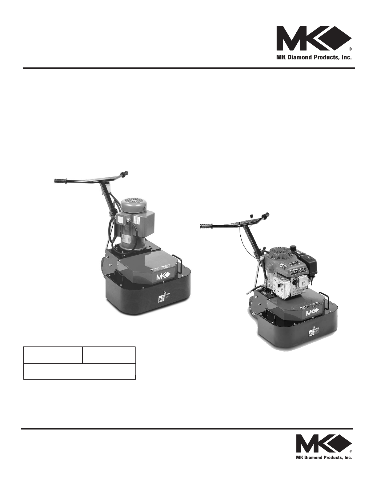
MK-DDG SERIES
OWNER'S MANUAL,
PARTS LIST &
OPERATING INSTRUCTIONS
MK-DDG-11
Revision 203
Manual 157499
Caution: Read all safety and operating instructions
before using this equipment. This parts list MUST
accompany the equipment at all times.
12.2011
MK-DDG-5
Page 2
INTRODUCTION
Congratulations on your purchase of a MK-DDG. We are certain that you will be pleased with your
purchase. MK Diamond takes pride in producing the finest construction power tools and diamond
blades in the industry.
Operated correctly, your MK-DDG should provide you with years of service. In order to help you,
we have included this manual. This owners manual contains information necessary to operate and
maintain your MK-DDG safely and correctly. Please take a few minutes to familiarize yourself with
the MK-DDG by reading and reviewing this manual.
If you should have questions concerning your MK-DDG, please feel free to call our friendly
customer service department at: 800 421-5830
Regards,
MK Diamond
NOTE THIS INFORMATION FOR FUTURE USE:
MODEL NUMBER:
SERIAL NUMBER:
PURCHASE PLACE:
PURCHASE DATE:
NOTE: For your (1) one year warranty to be effective, complete the warranty card
(including the Serial Number) and mail it in as soon as possible.
2
Page 3

TABLE OF CONTENTS
SAFETY
Safety Messages 4
Damage Prevention and Information Messages 4
Safety Precautions 4
California Proposition 65 Message 6
Hazard Symbols 7
Electrical Requirements and Grounding Instructions 8
Double Disc Grinder Specic Warnings 10
Safety Label Locations 10
Product Specications 11
UNPACKING, TRANSPORT, STAND and ASSEMBLY
Unpacking 12
Contents 12
Transport 12
ASSEMBLY and OPERATION
Handlebar Adjustment 13
Grinding Discs Installation 13
Gasoline Engine Unit 14
Electric Motor Unit 14
MAINTENANCE AND TROUBLESHOOTING
Clean Up 15
Filling Fuel Tank 15
EXPLODED VIEW AND PARTS LIST
Exploded View 16
Parts List 19
ACCESSORIES
Accessories 25
ORDERING & RETURN INSTRUCTIONS
Ordering Information 26
Return Materials Policy 26
Packaging Instructions 26
Authorized Service Centers 26
CONTACT& LIMITED WARRANTY
Contact & Limited Warranty 27
3
Page 4
MK-DDG SERIES SAFETY
Read and follow all safety, operating and maintenance instructions. Failure to read and follow
these instructions could result in injury or death to you or others. Failure to read and follow these
instructions could also result in damage and/or reduced equipment life.
SAFETY MESSAGES
A safety message alerts you to potential hazards that could hurt you or others. Each safety message is preceded by a safety alert symbol ( ) and one of three words: DANGER, WARNING, or CAUTION.
DANGER
WARNING
CAUTION
You WILL be KILLED or SERIOUSLY INJURED if you do not follow directions.
You CAN be KILLED or SERIOUSLY INJURED if you do not follow directions.
You CAN be INJURED if you do not follow directions. It may also be used to alert
against unsafe practices.
DAMAGE PREVENTION AND INFORMATION MESSAGES:
A Damage Prevention Message is to inform the user of important information and/or instructions that
could lead to equipment or other property damage if not followed. Information Messages convey
information that pertains to the equipment being used. Each message will be preceded by the word
NOTE, as in the example below.
NOTE:
GENERAL SAFETY PRECAUTIONS AND HAZARD SYMBOLS
Equipment and/or property damage may result if these instructions are not followed.
In order to prevent injury, the following safety precautions and symbols should be followed at all times!
SAFETY PRECAUTIONS
ALWAYS read this Owner’s Manual before operating the machine.
ALWAYS keep the Blade Guards in place.
REMOVE ADJUSTING KEYS AND WRENCHES
Form a habit of checking to see that keys and adjusting wrenches are removed from
the power tool before it is turned on.
KEEP WORK AREA CLEAN
Cluttered work areas and benches invite accidents.
DO NOT USE IN DANGEROUS PLACES
DO NOT use power tools in damp or wet locations nor expose them to rain. Always
keep the work area well lighted.
KEEP CHILDREN AWAY
All visitors and children should be kept a safe distance from work area.
4
Page 5
MK-DDG SERIES SAFETY
MAKE THE WORKSHOP KID PROOF
Make the workshops kid proof by using padlocks, master switches or by removing starter
keys.
DO NOT FORCE THE TOOL
A power tool will do a job better and safer operating at the rate for which it was designed.
USE THE RIGHT TOOL
DO NOT force a tool or an attachment, to do a job that it was not designed to do.
USE THE PROPER EXTENSION CORD
If using an extension cord make sure it is in good condition first. When using an extension
cord, be sure to use one heavy enough to carry the current your product will draw. An
undersized cord will cause a drop in line voltage that will result in a loss of power and
overheating. TABLE 1, Page 10 shows the correct AWG size to use depending on cord
length and nameplate ampere rating. If in doubt, use the next heavier gage. The smaller
the gage number, the heavier the cord.
USE PROPER APPAREL
DO NOT wear loose clothing, gloves, neckties, rings, bracelets, or other jewelry that may
be caught in moving parts. Non-slip footwear is recommended. Wear protective hair
covering to contain long hair.
ALWAYS wear approved eye protection.
ALWAYS wear approved respiratory protection.
SECURE WORK
Clamps or a vise should be used to hold work whenever practical. Keeping your
hands free to operate a power tool is safer.
DO NOT OVERREACH
Keep proper footing and balance at all times by not overreaching.
MAINTAIN TOOLS WITH CARE
Keep tools clean for the best and safest performance. Always follow maintenance
instructions for lubricating, and when changing accessories.
ON / OFF
DISCONNECT TOOLS
Power tools should always be disconnected before servicing or when changing
accessories, such as blades, bits, cutters, and the like.
ALWAYS place the power ON/OFF switch in the OFF position when the saw is not in use.
5
Page 6

MK-DDG SERIES SAFETY
USE RECOMMENDED ACCESSORIES
Consult the owner’s manual for recommended accessories. Using improper accessories
may increase the risk of personal or by-stander injury.
NEVER STAND ON THE TOOL
Serious injury could occur if a power tool is tipped, or if a cutting tool is unintentionally
contacted.
CHECK FOR DAMAGED PARTS
Before using a power tool, check for damaged part. A guard or any other part that is
damaged should be carefully checked to determine if would operate properly and perform
its intended function. Always check moving parts for proper alignment or binding. Check
for broken parts and mountings and all other conditions that may affect the operation of
the power tool. A guard, or any damaged part, should be properly repaired or replaced.
DIRECTION OF FEED
ALWAYS feed work into a blade or cutter against the direction of rotation. A blade
or cutter should always be installed such that rotation is in the direction of the arrow
imprinted on the side of the blade or cutter.
NEVER LEAVE A TOOL UNATTENDED
TURN POWER OFF - Do not leave a tool until it comes to a complete stop. Always
turn a power tool OFF when leaving the work area, or, when a cut is finished.
CALIFORNIA PROPOSITION 65 MESSAGE
WARNING
Some dust created by power sanding, sawing, grinding, drilling, and other construction activities contain chemicals known (to the State of California) to cause cancer, birth defects or other reproductive
harm. Some examples of these chemicals are:
• Lead, from lead-based paints
• Crystalline silica, from bricks and cement and other masonry products
• Arsenic and chromium, from chemically treated lumber
For further information, consult the following sources:
http://www.osha.gov/dsg/topics/silicacrystalline/index.html
http://www.cdc.gov/niosh/consilic.html
http://oehha.ca.gov/prop65/law/P65law72003.html
http://www.dir.ca.gov/Title8/sub4.html
Your risk from these exposures varies depending on how often you do this type of work. To reduce
your exposure to these chemicals, work in a well-ventilated area, and work with approved safety
equipment, such as those dust masks that are specially designed to lter out microscopic particles.
6
Page 7
MK-DDG SERIES SAFETY
)
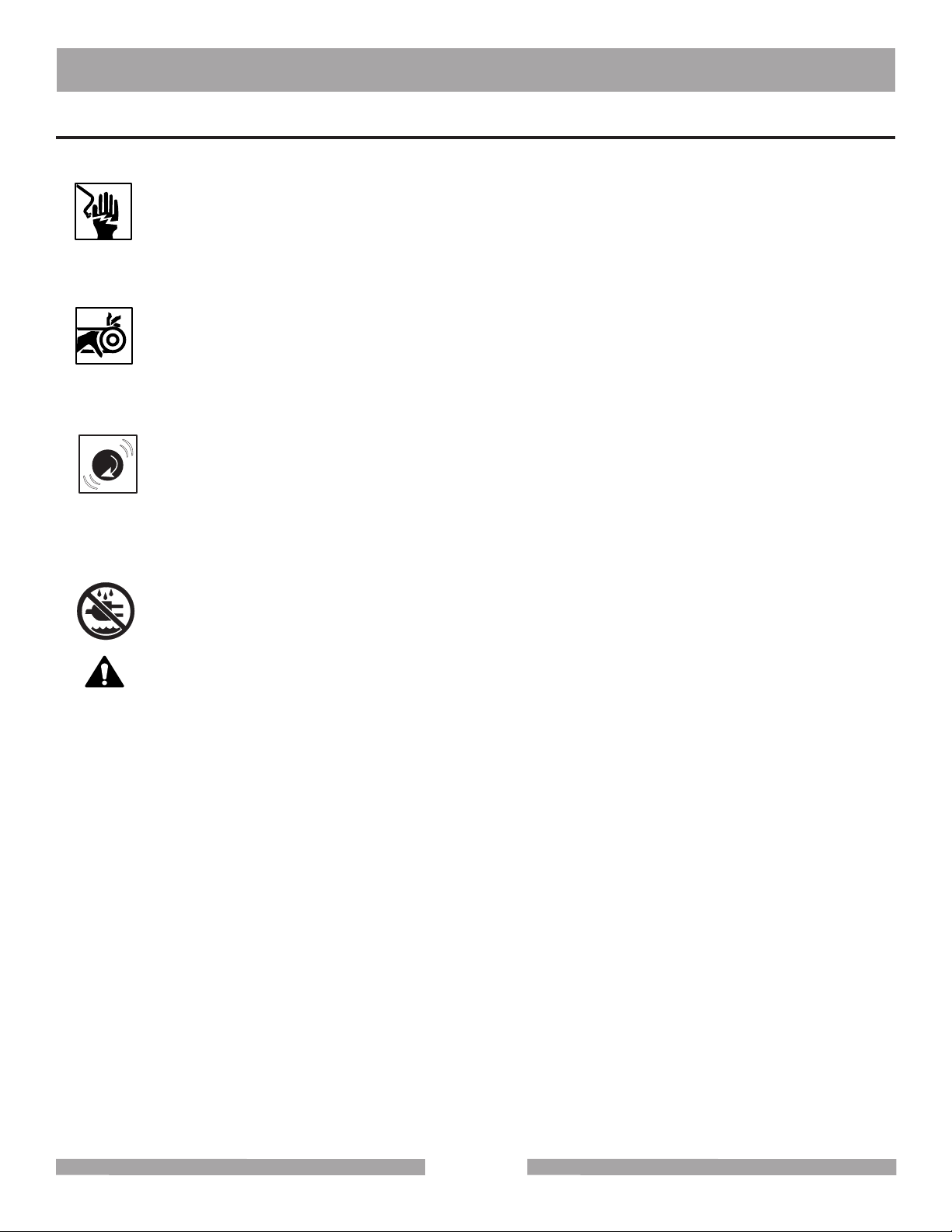
HAZARD SYMBOLS
ELECTRICAL SHOCK
NEVER touch electrical wires or components while the engine is running. They can be
sources of electrical shock which could cause severe injury or burns.
ROTATING PARTS
Keep hands, feet, hair, and clothing away from all moving parts to prevent injury.
Never operate the motor with covers, shrouds, or guards removed.
OVER SPEED
)
(
(
NEVER tamper with the governor components or settings to increase the maximum
speed. Severe personal injury and damage to the engine or equipment can result if
operated at speeds above maximum.
DO NOT EXPOSE TO RAIN
DO NOT expose to rain or use in damp locations.
WARNING
Sawing and drilling generates dust. Excessive airborne particles may cause irritation to eyes, skin
and respiratory tract. To avoid breathing impairment, always employ dust controls and protection
suitable to the material being sawed or drilled; See OSHA (29 CFR Part 1910.1200). Diamond
Blades improperly used are dangerous. Comply with American National Standards Institute Safety
Code, B7.1 and, Occupational Safety and Health Act covering Speed, Safety Guards, Flanges,
Mounting Procedures, General Operating Rules, Handling, Storage and General Machine Conditions
7
Page 8
MK-DDG SERIES SAFETY
ELECTRICAL REQUIREMENTS AND GROUNDING INSTRUCTIONS
In order to prevent potential electrical shock and injury, the following electrical safety precautions and
symbols should be followed at all times!
WARNING
In case of a malfunction or breakdown, grounding provides a path of least resistance for electric current to reduce the risk of electric shock. This tool is equipped with an electric cord having an equipment-grounding conductor and a grounding plug. The plug must be plugged into a matching outlet
that is properly installed and grounded in accordance with all local codes and ordinances.
• Do not modify the plug provided – if it will not t the outlet; have the proper outlet installed by a
qualied electrician
• Improper connections of the equipment-grounding conductor can result in a risk of electric
shock. The equipment-grounding conductor is the insulated conductor that has an outer
surface that is green, with or without yellow stripes. If repair or replacement of the electric cord
or plug is necessary, do not connect the equipment-grounding conductor to a live terminal
• Check with a qualied electrician or service personnel if the grounding instructions are not
completely understood, or if in doubt as to whether the tool is properly grounded
• Use only 3-wire extension cords that have 3-prong grounding plugs and 3-pole receptacles that
accept the tool’s plug
• Repair or replace a damaged or worn cord immediately
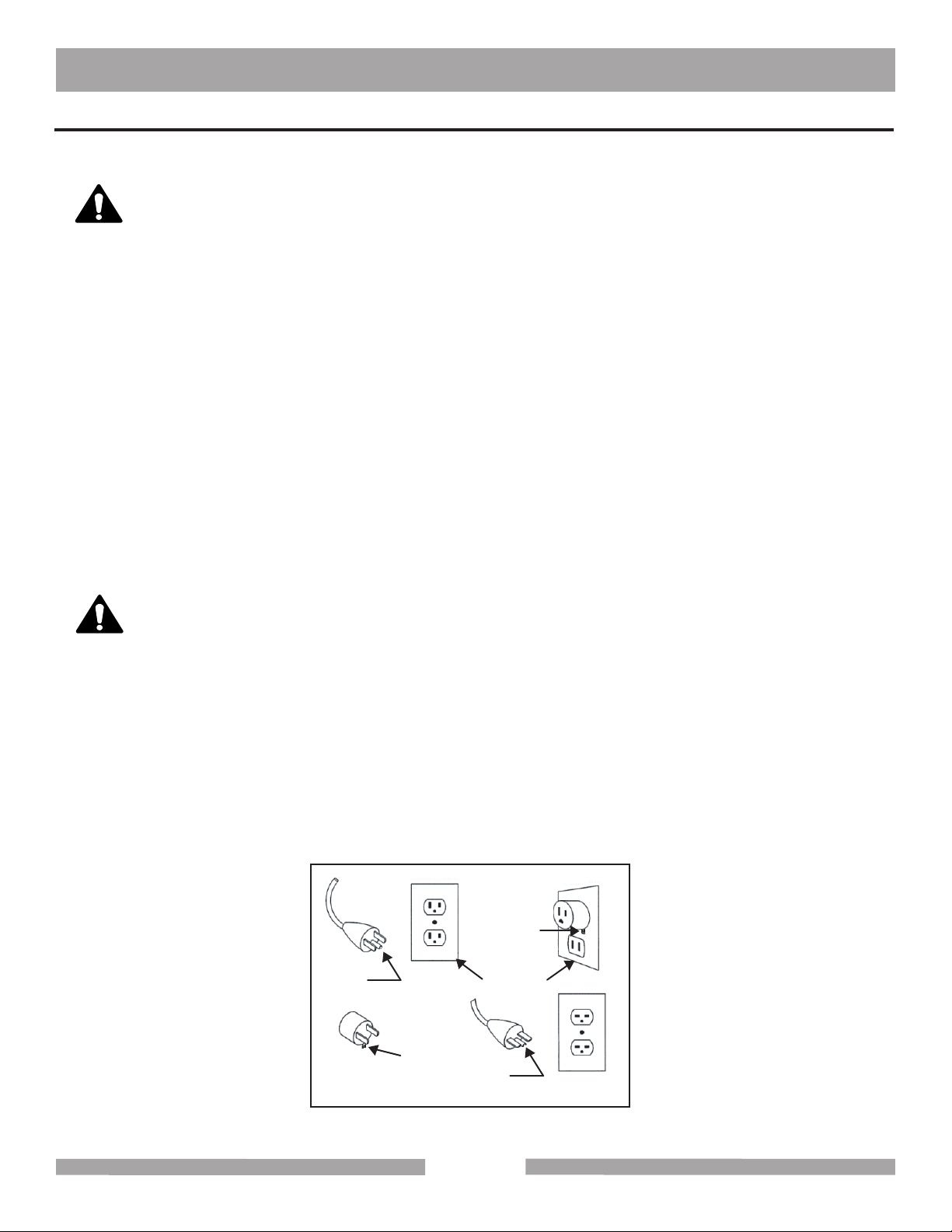
WARNING
This tool is intended for use on a circuit that has an outlet that looks like the one shown in Sketch A.
The tool has a grounding plug that looks like the plug illustrated in Sketch A. A temporary adapter,
which looks like the adapter illustrated in sketches B and C, may be used to connect this plug to a
2-pole receptacle as shown in Sketch B, if a properly grounded outlet is not available. The temporary
adapter should be used only until a properly grounded outlet can be installed by a qualied electrician. The green-colored rigid ear, lug, and the like, extending from the adapter, must be connected to
a permanent ground such as a properly grounded outlet box.
NOTE: Use of a temporary adapter is not permitted in Canada.
Metal Screw
Grounding
Pin
(A)
ADAPTER
Grounding
Means
(C)
Cover of
Grounded
Outlet Box
Grounding
Pin
(B)
(D)
Circuit and Adapter Information
8
Page 9
Surface
MK-DDG SERIES SAFETY
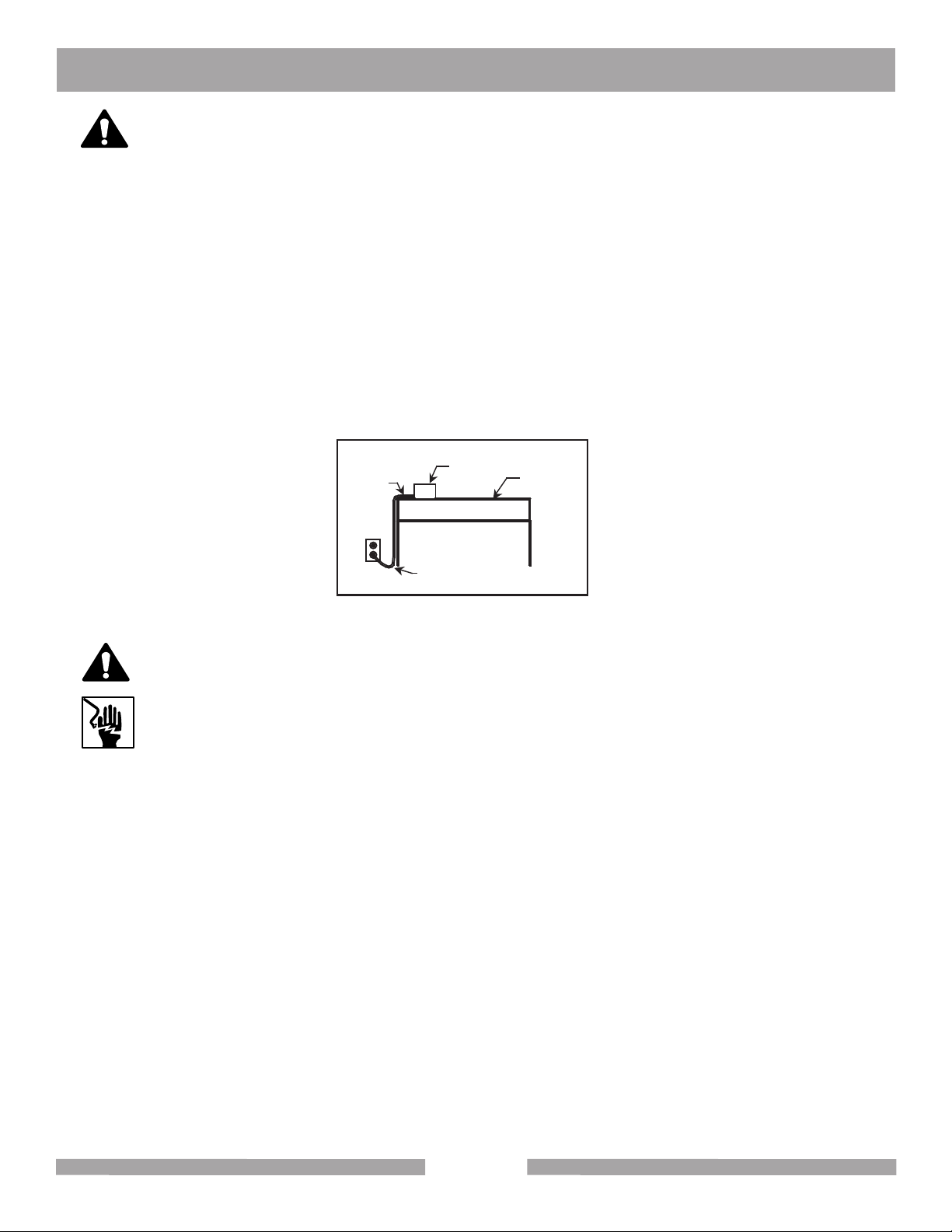
WARNING
To avoid the possibility of the appliance plug or receptacle getting wet, position the machine to one
side of a wall mounted receptacle. This will prevent water from dripping onto the receptacle or plug. A
“drip loop,” shown in the picture below, should be arranged by the user to properly position the power cord
relative to the power source.
The “drip loop” is that part of the cord below the level of the receptacle, or the connector, if an extension cord is used. This method of positioning the cord prevents the travel of water along the power
cord and coming in contact with the receptacle.
If the plug or receptacle gets wet, DO NOT unplug the cord. Disconnect the fuse or circuit breaker
that supplies power to the tool. Then unplug and examine for presence of water in the receptacle.
Power
Cord
Drip Loop Information
Power
Tool
Drip Loop
Supporting
WARNING
Use only extension cords that are intended for outdoor use. These extension cords are
identified by a marking “Acceptable for use with outdoor appliances; store indoors while
not in use." Use only extension cords having an electrical rating not less than the rating
of the product. Do not use damaged extension cords. Examine extension cords before
using and replace if damaged. Do not abuse extension cords and do not yank on any
cord to disconnect. Keep cords away from heat and sharp edges. Always disconnect the
extension cord from the receptacle before disconnecting the product from the extension
cord.
9
Page 10

MK-DDG SERIES SAFETY
WARNING
Wear eye protection.
Replace any damaged grinding discs before operating.
SAFETY LABEL LOCATIONS
Safety and warning labels are located according to the gure below. The labels contain important
safety information. Please read the information contained on each safety label. These labels are
considered a permanent part of your saw. If a label comes off or becomes hard to read, contact
MK Diamond or your dealer for a replacement.
CAUTION
WARNING
!
(A)
(B)
(C)
(D)
DO NOT operate
this equipment
before reading
the owners’
manual!
!
Grinding/cutting/drilling of masonry, concrete, metal and other materials with silica in
their composition may give off dust or mists containing crystalline silica. Silica is a basic
component of sand, quartz, brick clay, granite and numerous other minerals and rocks.
Repeated and/or substantial inhalation of airborne crystalline silica can cause serious
or fatal respiratory diseases, including silicosis. In addition, California and some other
authorities have listed respirable crystalline silica as a substance known to cause cancer.
!
DO NOT
operate without
guards in place.
!
Keep
hands and
feet clear.
WARNING
CAUTION
CAUTION
DANGER
!
The exhaust from this product
contains chemicals known to
(E)
the State of California to cause
cancer, birth defects or other
reproductive harm.
(F)
(G)
DANGER
Lethal exhaust
gases. Use only
in well ventilated
areas. DO NOT
use indoors.
WARNING
!
When refueling
stop engine and
allow to cool.
DO NOT overll
tank.
(H)
Accidental start hazard.
(I)
Disconnect spark plug
prior to servicing.
(J)
Overtensioning of belts
(K)
will result in premature
crank and/or bearing failure.
!
DO NOT
touch hot
surface.
CAUTION
!
FOR INFORMATION ON
SERVICE OR
WARRANTY
PLEASE CALL
1-800-474-5594
NOTICE
!
!
NOTICE
Most Motor Problems are caused by improper
Label Sheet Part# 166010
B
voltage and extension cords. Cord should be
one-piece and short as possible. Cord
selection should match the following table.
(L)
1-2 H.P.
5 H.P.
230v
115v 230v
50’
25’
100’
100’
50’
150’
150’
75’
250’
250’
Max. Cord Lgth.
Max. Cord Lgth.
Max. Cord Lgth.
Max. Cord Lgth.
No. 12 Wire
No. 10 Wire
No. 8 Wire
No. 6 Wire
Electric Engine
A
H
J
J
D
I
C
E
C
MK-DDG-11
10
Page 11

MK-DDG SERIES SAFETY
PRODUCT SPECIFICATIONS
The MK-DDG is a versatile unit. Operated and used according to this manual, the MK-DDG will
provide years of dependable service.
Features
• Uses two 10 or 20 segment 10" diameter diamond grinding discs to level, smooth or
clean the top surface of concrete slabs.
• Provides a smoother nish compared to other methods such as scariers or scrabblers.
• Counter rotating discs provide balanced torque to prevent pulling left or right
• Can also be used to level small areas of uneven joints or high spots of 1/16" to 1/8".
• A 22-inch grinding width makes for quick removal.
• Wide ergonomically designed T-grip handle for easy handling and maneuvering.
• Dust shroud contains grinding debris.
• 2" vacuum port standard for dust-free operation.
• Two-position wheel carriage for grinding and easy transport.
• Works on concrete slabs, terrazzo, brick, stone and ceramic tile oors.
Specifications
Specications for the MK-DDG are listed in the table below.
Model
Engine
Power GXV340
Disc RPM
Disc Capacity
Weight
LxWxH (inches)
LxWxH (mm)
Part #
MK-DDG-11
Honda
550
10" (254mm)
239 lbs. (108kg)
50" x 25" x 40" 50" x 25" x 40"
1,270 x 635 x 1,016 1,270 x 635 x 1,016
157012
MK-DDG-5 Electric
Baldor / Leeson
5 HP
550
10" (254mm)
295 lbs. (134kg)
158780
11
Page 12

MK-DDG SERIES CONTENT
UNPACKING
Use proper lifting techniques when lifting the MK-DDG
If not done, remove the MK-DDG, accessory box from the carton.
CONTENTS
In your container, you will find
One (1) MK-DDG
One (1) MK-DDG Owner's Manual
One (1) Honda Owner's Manual
One (1) Warranty Card
MK-DDG
TRANSPORT
CAUTION
www.mkdiamond.com
Revision 203
Manual 157499
Caution: Read all safety and operating instructions
before using this equipment. This parts list MUST
accompany the equipment at all times.
Owner's Manual
MK-DDG-11
11.2011
MK-DDG SERIES
OWNER'S MANUAL,
PARTS LIST &
OPERATING INSTRUCTIONS
MK-DDG-5
Honda Owners Manual
(Gas Powered Only)
Warranty
Card
1. The MK-DDG weighs approximately two hundred and thirty nine (239)
pounds; use care when transporting. The unit needs to be rolled from one
location to another.
2. Never try to lift the unit by yourself.
Handle
Adjustable
Wheels
Two Lift
Points
12
Page 13

MK-DDG SERIES ASSEMBLY
ASSEMBLY
Follow the diagram below to prepare your MK-DDG for operation.
Handlebar Adjustment
Adjust the Handlebar, as shown on the Figure to the right,
for ease of operation and comfort of the user.
Grinding Discs Assembly
You need to install the grinding discs before
operation of the MK-DDG
The Figure to the left shows
hardware and installation of discs.
Unit ready for operation.One disc installed.Grinding Wheel Mount
Operate on concrete
surface
Both grinding discs at
work
13
Check the surface
Page 14

MK-DDG SERIES START
FOR GASOLINE ENGINE
BEFORE STARTING
1. Use correct diamond wheel for grinding conditions.
2. Ensure wheel mountings are clean and bolts are tightened securely.
3. Check for adequate water flow.
TO BEGIN GRINDING OPERATION
1. Place grinding wheels on surface.
2. Start and warm up engine.
3. If application requires water, adjust water flow.
4. Adjust speed as required by application.
DAILY MAINTENANCE
1. Check engine oil level.
2. Check and clean air filter.
3. Lubricate grease points.
4. Check belt tension
5. Check for fluid leaks and loose or damaged parts.
FOR ELECTRIC MOTOR
BEFORE STARTING
1. Choose correct diamond wheels for the job condition.
2. Ensure grinding wheel mountings are clean and the
retaining bolts are securely tightened.
3. Check for adequate water flow.
TO BEGIN GRINDING OPERATION
1. Be sure the grinding wheels are positioned over the work area.
2. If application requires water, adjust water flow.
3. While holding securely to the handlebar,
turn power switch to "ON" position.
DAILY MAINTENANCE
1. Lubricate grease points.
2. Check belt tension.
14
Page 15

MK-DDG SERIES CLEAN UP
CLEAN UP
CAUTION
NOTE:
1. To extend operating life, the MK-DDG should be cleaned following every use.
2. Use care when using a garden hose or pressure washer. These could force water
into the air cleaner or muffler opening.
3. Use care when cleaning around electrical components.
FILLING FUEL TANK
WARNING
1. Gasoline is highly flammable and explosive. You can be burned or seriously injured when
handling fuel.
2. To fuel, stop engine if running, and allow it to cool.
3. Refuel in a well-ventilated area.
4. Keep gasoline away from appliance pilot lights, barbecues, electric appliances, power
tools, etc.
5. Wipe up spills immediately
Engine parts are extremely hot following use. Allow engine to cool 1/2 hour
before cleaning.
Use care during cleanup to avoid injury.
NOTE:
1. Fuel can damage paint and plastic. Be careful not to spill fuel when filling the fuel tank.
2. Damage caused by spilled fuel IS NOT covered under the warranty.
3. DO NOT use stale or contaminated gasoline, or an oil/gasoline mixture.
4. Use unleaded gasoline with a pump octane rating of 86 or higher.
Do not overfill the
Gas Tank
15
Page 16

MK-DDG SERIES EXPLODED VIEW
EXPLODED VIEW WITH GAS ENGINE
16
Page 17

MK-DDG SERIES EXPLODED VIEW
EXPLODED VIEW WITH ELECTRIC MOTOR
17
Page 18

MK-DDG SERIES EXPLODED VIEW
18
Page 19

MK-DDG SERIES PARTS LIST
Item Description Part # Qty
A Assembly, Accessory Pack - A1 Grinding Wheels 10” (Reference only) reference 0
A2 Pallet (not shown) 157700 1
A3 Carton, DDG-11 Grinder (not shown) 157701 1
A4 Carton, DDG-11 Top (not shown) 158369 1
A5 Carton, DDG-11 Inserts (not shown) 158370 2
A6 Tube, Owner’s Manual (not shown) 155419 1
A7 Manual, Owner’s (not shown) 157499 1
A8 Bolt, Hex HD, 3/8-24 x 1 Grinding Disk, Mounting 157803 8
A9 Washer, 3/8 Split Lock 150925 8
A10 Washer, 3/8 Flat SAE 150923 8
B Assembly, Frame 157381 1
B1 Frame Weldment 157068 1
B2 Plate, Serial Number 157500 1
B3 #7 X 5/16 Drive Screw 157849 4
B4 Label, Water Shut Off/On 154404 1
C Assembly, Apron - 1
C1 Apron, 157064 1
C2 Plate, Vacuum 157255 1
C3 Cap, Vacuum Attachment 157503 1
C4 Screw, 5/16-18 x 1-1/4 Hex Head 153950 4
C5 Washer, 5/16 lock, split 151747 5
C6 Washer, 5/16 SAE Flat 151754 5
C7 Screw, 5/16-18 x 3/4 Hex Head 151369 1
C8 Label, Caution, Hands and Feet 155585 1
D Assembly, Belt Guard - 1
D1 Guard, Belt 157069 1
D2 Screw, ¼-20 X 1 Hex Head Cap 152676 2
D3 Washer, 1/4 SAE Flat 151915 4
D4 Nut, Hex W/ WSHR 1/4-20 (KEPS) 153941 2
D5 V-Belt (V AX-25) 152403 2
D6 Label, MK Logo Adhesive 157914 1
D7 Label, Caution, Belt Tension 155583 1
D8 Label, Caution, Guards in Place 155587 1
E Assembly, Gear, Cover - 1
E1 Cover, Gear 157066 1
E2 Screw, 1/4-20 x 3/4 Hex Head Cap 152370 9
E3 Washer, 1/4 Split Lock 152591 9
E4 Washer, 1/4 SAE Flat 151915 9
E5 Cap, Grease 157915 1
F Assembly, Components, Gear Box - F1 Flange unit, 1” dia 4 Bolt (Bearing) 157305 4
F2 Washer, 7/16 Flat SAE 151050 16
F3 Washer, 7/16 Split Lock 151051 16
19
Page 20

MK-DDG SERIES PARTS LIST
Item Description Part # Qty
F4 Nut, 7/16-14, Hex 150922 16
F5 Flange unit, 3/4” dia 4 Bolt (Bearing) 157304 2
F6 Washer, 3/8 Flat SAE 150923 8
F7 Washer, 3/8 Split Lock 150925 8
F8 Nut, 3/8-16, Hex 101188 8
F9 Shaft, 1” dia Large Gear 157302 2
F10 Flexible Mount, Morflex (Morse 402 Insert) 157411 2
F11 Mount, Grinding Wheel 157407 2
F12 Screw, 3/8-16 x 2 1/2 Hex HD Cap 156030 4
F13 Screw, 3/8-16 x 2 1/2 Flt. Soc. HD. 157562 4
F14 Nut, 3/8-16, Hex Nylock 152505 8
F15 Bushing, 1 ¼ OD x 1 ID x ½ Spacer 157410 2
F16 Gear, 11 ½” dia Spur (Cast 10P 112T-14 ½ PA) 157306 2
F17 Key, Square, 1/4 x 1/4 x 1 ¼” 159852 2
F18 Shaft, ¾” dia Small Gear 157303 1
F19 Gear, 2 1/2” dia Spur (Steel 10P 25T-14 ½ PA) 157307 1
F20 Pin, 1/4 x 1 1/2” Rolled 157565 1
F21 Pulley, 2AK51H
F21A) Bushing, H 3/4 Q.D.
F22 Key, Square, 3/16 x 3/16 x 1 ¾ 157561 1
159849
159850
1
1
G Assembly, Engine, 11HP Honda - 1
G1 Engine, Honda GX340k2dx3 157067 1
G2 Clutch, 3 ½” OD with 1” I.D. 3 ½” 2 Groove Pulley, 157309 1
G3 Key, Square, 1/4 x 1/4 x 1 ½” 157560 1
G4 Bolt, 7/16-20 x 3” Hex Head 157678 1
G5 Washer, 1 /2” USS 157679 1
G6 Washer, 7/16 Split Lock 151051 1
G7 Spacer, 1 ¼” OD, 1” I.D. x 1 3/8” 157680 1
G8 Spacer, 1” OD, ½” I.D. x 2” 157681 1
G9 Screw, 5/16-18 x 1 1/2” Hex Head Cap 152467 2
G10 Bolt, 5/16-24 x 1” Hex Head Tap 157646 2
G11 Washer, 5/16 SAE Flat 101352 5
G12 Washer, 5/16 Split Lock 151747 5
G13 Nut, 5/16-18 Hex 101196 3
G14 Bolt, 5/16-18 x 2 ¾” Hex Head Tap 156974 1
G15 Mount, Engine 157071 1
G16 Screw, 3/8-16 x 1” Carriage Bolt 157644 4
G17 Washer, 3/8 SAE Flat 150923 4
G18 Washer, 3/8 Split Lock 150925 4
G19 Nut, 3/8-16 Hex 101188 4
G20 Hose, Oil Drain (20mm) 157577-04 1
G21 Label, Caution, Hot Surface, 1.5 x 3.0 155578 1
G22 Label, Warning, Refueling, 1.5 x 3.0 155580 1
G23 Label, Danger, California, 1.5 x 3.0 155581 1
G24 Label, Danger, Lethal Exhaust, 1.5 x 3.0 155582 1
G25 Label, Caution, Sparkplug 155579 1
G26 Label, Control Panel (Gas) 157075 1
20
Page 21

MK-DDG SERIES PARTS LIST
Item Description Part # Qty
GB Assembly, 5hp Electric Motor GB1 Motor, 5 hp 230v 60hz 1ph, Electric C’ face (Lesson / Baldor) 160107 1
GB2 Pulley, 2BK34X 1 1/8 160108 1
GB3 Key, Square, 1/4 x 1/4 x 1 3/4” 150796 1
GB4 Mount, Engine 157071 1
GB5 Screw, 1/2-13 x 1 1/4 UNC Hex Head 153532 4
GB6 Washer, 1/2 Split Lock 153524 4
GB7 Screw, 3/8-16 x 1” Carriage Bolt 157644 4
GB8 Washer, 3/8 SAE Flat 150923 4
GB9 Washer, 3/8 Split Lock 150925 4
GB10 Nut, 3/8-16 Hex 101188 4
GB11 Washer, 5/16 Split Lock 151747 5
GB12 Nut, 5/16-18 Hex 101196 3
GB13 Bolt, 5/16-18 x 2 ¾” Hex Head Tap 156974 1
GB14 Bracket, Switchbox (previous #227269) 160110 1
GB15 Screw, 1/4-20 x 3/4” Pan HD Phil Cap 227270 2
GB16 Screw, 1/4-20 x 1/2 Hex Head Cap 152608 2
GB17 Washer, 1/4 Split Lock 152591 4
GB18 Washer, 1/4 SAE Flat 151915 4
GB19 Nut, 1/4-20 Hex 151893 2
GB20 Label, Control Panel, (Electric) 160109 1
H Assembly, Axle - 1
H1 Wheel, 8”Dia. X2 155986 2
H2 Collar, 3/4 set 153814 2
H3 Axle, 3/4 Dia. 157065 1
H4 Mount, Wheel Shaft, 157072 2
H5 Screw, 1/2-13 x 1 1/4 UNC Hex Head 153532 2
H6 Washer, 1/2 SAE Flat 150924 4
H7 Washer, 1/2 Split Lock 153524 2
J Assembly, Handlebar (Top & Bottom) - 1
J1 Handlebar, Top 157260 1
J2 Handgrip 150842 2
J3 Handlebar, Bottom 157070 1
J4 Screw, 3/8-16 X 1 Hex Head Cap 152507 1
J5 Screw, 3/8-16 X 1 1/4 Hex Head Cap 150774 4
J6 Screw, 3/8-16 X 3 Hex Head Cap 153113 4
J7 Washer, 3/8 SAE Flat 150923 8
J8 Washer, 3/8 Split Lock 150925 6
J9 Nut, 3/8-16 Hex 101188 2
K Assembly, Throttle, Honda - 1
K1 Screw, (Phil) Self Tap 10-24 x 5/8 153681 2
K2 Nut, 10-24 Clip 155407 2
K3 Assembly, Throttle Head 155406 1
K4 Cable, Throttle, Honda 156640 1
L Assembly, Choke, Honda - 1
21
Page 22

MK-DDG SERIES PARTS LIST
Item Description Part # Qty
L1 Cable, Choke 154210 1
L2 Washer, 3/8 SAE Flat 150923 4
L3 Nut, 3/8-24 Hex, Jam 156623 1
L4 Screw, 10-32 X 1/2” Pan Head Phillips Cap 151052 1
L5 Clamp, Transmission Control 154383 1
L6 Screw, (Phil) Self Tap 10-24 x 5/8 153681 1
L7 Clip, Choke Cable 157504 1
L8 Nut, 10-24 Clip 155407 1
M Assembly, Water Valve - 1
M1 Screw, 10-24 x 3/8 Phillips Head Self-Tapping Cap 151262 2
M2 Fitting, Brass, 1/2 MNPT x Garden Hose Swivel 151322 1
M3 Elbow, ½ MNPT 90° Street Galvanized 150844 1
M4 Valve, Shut-Off, 1/2 FNPT x 1/2 FNPT 153796 1
M5 Fitting, Brass, 1/2 MNPT x 1/4 Compression Fit 157563 1
M6 Tube, ¼ OD Copper 157564 2’
22
Page 23

NOTES
23
Page 24

NOTES
24
Page 25

MK-DDG SERIES ACCESSORIES
ACCESSORIES
ITEM NUMBER DESCRIPTION
10 Segments
1. 151925
1010 S soft Bond; Hard Material; Cured or Old
10 Segments
2. 158151
1010 H Hard Bond; Soft Material; Green Asphalt
20 Segment
3. 151926
1020 S soft Bond; Hard Material; Cured or Old
4. 158182
20 Segments
1010 H Hard Bond; Soft Material; Green Asphalt
25
Page 26

MK-DDG SERIES ORDERING, RETURN, & PACKAGING
ORDERING INFORMATION
You may order MK Diamond products through your local MK Diamond distributor or, you may order
direct from MK Diamond.
When ordering direct from MK Diamond, please have the following information ready before calling:
• The Model Number of the saw
• The Serial Number of the saw
• Where the saw was purchased and when
• The Part Number for the part(s) being ordered
• The Part Description for the part(s) being ordered
NOTE: There is a $25.00 minimum order when ordering direct from MK Diamond. A $5.00 charge will
be added to orders having a net billing value under $50.00. All purchases must be made using VISA,
MasterCard or American Express.
All parts may be ordered by calling toll free to – 800 421-5830 or 310 539-5221 and asking for
Customer Service. For technical questions, call – 800 474-5594.
RETURN MATERIALS POLICY
To expedite the service relative to the return of a product purchased through MK Diamond, please
observe the following:
NOTE: When returning all items, they must have been purchased within the previous twelve (12)
months.
• Have the Model Number of the saw
• Have the Serial Number of the saw
• Have the location of where the saw was purchased
• Have the date when the saw was purchased
• Contact Customer Service for approval to return the item(s)
• Obtain a Returned Goods Number (RGA) authorizing the return
• Follow the packaging instructions in the following section
• Ensure your item(s) are prepaid to the destination
For returned items, call toll free to – 800 421-5830 or 310 539-5221 and ask for Customer Service.
For technical questions, call – 800 474-5594 or 310 257-2845.
PACKAGING INSTRUCTIONS
• Remove the Cutting Head and Support Angle Assembly
• Dry the saw before shipping
• When packing, include the following: MK-DDG and Grinding Head (Other Accessories are not
required)
• Package the unit in its original container or one of comparable size (do not ship the unit partially
exposed)
• Ensure all parts are secured in the packaging to prevent moving
AUTHORIZED SERVICE CENTERS
For quicker repair time, you may contact MK Diamond Customer Service, toll free, at 800 421-5830
or 310 539-5221 for the Authorized Service Center closest too you or visit our web site at www.mkdiamond.com. For technical questions, call – 800 474-5594.
26
Page 27

MK-DDG SERIES CONTACT & LIMITED WARRANTY
CONTACT
Please contact MK Diamond Products, Inc. Customer Service Department with any questions you
might have regarding distributors, parts or service.
Telephone: (800) 421-5830
Fax: (310) 539-5158
E-mail: Customer_Service@MKDiamond.com
Customer Service Hours: Monday through Friday, 6AM-4PM PST
MK Diamond Products, Inc.
1315 Storm Parkway
Torrance, CA 90501
MK DIAMOND PRODUCTS, INC. LIMITED WARRANTY
MK DIAMOND PRODUCTS, INC. will guarantee every machine they build, to be free from defects in
material and workmanship for (1) one year from date of purchase. The obligation of MK DIAMOND
PRODUCTS, INC. under this warranty is limited to the repair or replacement of any parts which,
under normal use, prove to be defective in material or workmanship. The parts involved or the unit
in question should be returned to MK DIAMOND PRODUCTS, INC. or to a point designated by us,
transportation prepaid.
This warranty does not obligate us to bear the cost of labor or transportation charges in connection
with replacement or repair of defective parts. Likewise, it shall NOT apply to any unit which has been
subjected to misuse, neglect or accident. This warranty does NOT apply to any machine which has
been repaired or altered outside our factory.
This warranty does NOT obligate MK DIAMOND PRODUCTS, INC., with respect to items not of our
manufacture, such as engines, motors, hydraulics, etc., which are subject to their own guarantees and
warranties.
We shall in no event be liable for consequential damages or contingent liabilities arising out of failure
of any equipment or parts to operate properly.
© COPYRIGHT 2011, MK DIAMOND PRODUCTS, INC. ALL RIGHTS RESERVED.
The MK Diamond logo is a registered trademark of MK Diamond Products, Inc. and may not be used,
reproduced, or altered without written permission. All other trademarks are the property of their respective owners and used with permission.
MK Diamond may have patents, patent applications, trade marks, copyrights of other intellectual
property right covering this product in this document.
This manual MUST accompany the equipment at all times. This manual is considered a permanent
part of the equipment and should remain with the unit if resold.
The information and specications included in this publication were in effect at the time of approval for
printing.
27
Page 28

MK-DDG SERIES
OWNER'S MANUAL, PARTS LIST &
OPERATING INSTRUCTIONS
MK Diamond Products, Inc.
1315 Storm Parkway
Torrance, CA 90501
Toll-Free: (800) 421-5830
Phone: (310) 539-5221
Fax: (310) 539-5158
www.mkdiamond.com
 Loading...