

Page 1
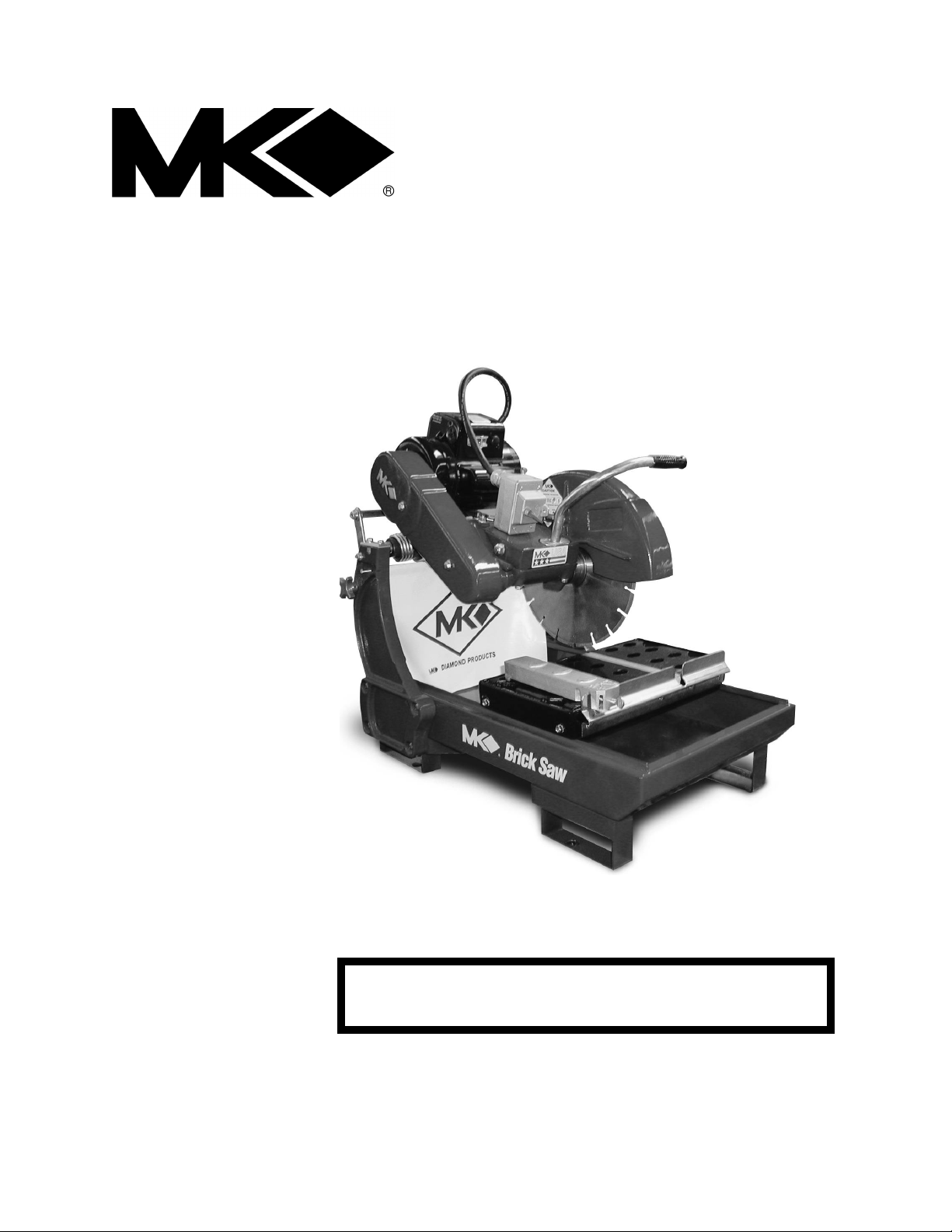
MK-2000 PRO SERIES
equipment
BRICK SAW
SERIAL NUMBER:
OWNER’S MANUAL &
OPERATING INSTRUCTIONS
CAUTION:
Read all safety and
operating instructions
before using this
Enter the Serial Number of your new saw in the
space below. The Serial Number is located on the
left side of the blade guard.
NOTE:
For your (1) one year warranty to be effective,
complete the warranty card (including the Serial
Number and mail it in as soon as possible.
Page 2

INTRODUCTION
We at MK Diamond want to congratulate you on selecting the MK-2000 PRO Brick Saw. We are certain that
you will be pleased with your purchase. MK Diamond takes pride in producing the finest products in the
industry.
Operated correctly, your MK-2000 PRO should provide you with years of quality service. In order to help you,
we have included this manual. This owners manual contains information necessary to operate and maintain
your MK-2000 PRO safely and correctly. Please take a few minutes to familiarize yourself with the MK-2000
PRO by reading and reviewing this manual.
If you should have questions concerning your MK-2000 PRO, please feel free to call our friendly customer
service department at: 800 421-5830
Regards,
MK Diamond
MK-2000 Pro Revision 01/02, Effective Date January 10, 2002 Page 2
Page 3

TABLE OF CONTENTS
SAFETY:
Safety Messages 4
Damage Prevention Message 4
General Safety Precautions and Hazard Symbols 4
California Proposition 65 Message 6
Electrical Requirements and Grounding Instructions 7
Safety Label Locations 9
Brick Saw Specific Warnings 9
Product Specifications 10
UNPACKING, TRANSPORT, UNIVERSAL STAND, and ASSEMBLY
Unpacking 11
Contents 11
Transport 11
Universal Stand 12
Assembly 12
SETUP, ADJUSTMENT AND OPERATION
Setup 15
Adjustment and Operation 18
Cleanup 23
MAINTENANCE AND TROUBLESHOOTING
Maintenance 25
Troubleshooting 33
Page
EXPLODED VIEW AND PARTS LIST
Exploded View 37
Parts List 38
THEORY
Theory of Diamond Saws 43
ACCESSORIES
Accessories 44
ORDERING and RETURN INSTRUCTIONS
Ordering Information 45
Return Material Policy 45
Packaging Instructions 45
Authorized Service Centers 45
Manual Part No. 158753 Revision No. 01/02
MK-2000 Pro Revision 01/02, Effective Date January 10, 2002 Page 3
Page 4
SAFETY
Read and follow all safety, operating and maintenance instructions. Failure to read and follow these
instructions could result in injury or death to you or others. Failure to read and follow these instructions could
also result in damage and/or reduced equipment life.
SAFETY MESSAGES:
Safety messages inform the user about potential hazards that could lead to injury, death and/or equipment
damage. Each safety message will be preceded by one of the following (3) three words that identify the
severity of the message.
Not following instructions WILL lead to DEATH or SERIOUS INJURY
Not following instructions COULD lead to DEATH or SERIOUS INJURY
Not following instructions CAN lead to injury
DAMAGE PREVENTION AND INFORMATION MESSAGES:
A Damage Prevention Message is to inform the user of important information and/or instructions that could
lead to equipment or other property damage if not followed. Information Messages convey information that
pertains to the equipment being used. Each message will be preceded by the word NOTE, as in the example
below.
NOTE:
Equipment and/or property damage may result if these instructions are not followed.
GENERAL SAFETY PRECAUTIONS AND HAZARD SYMBOLS:
In order to prevent injury, the following safety precautions and symbols should be followed at all times!
Safety Precautions:
KEEP GUARDS IN PLACE.
In order to prevent injury, keep guards in place and in working order at all times.
REMOVE ADJUSTING KEYS AND WRENCHES.
Form a habit of checking to see that keys and adjusting wrenches are removed from the power tool before it
is turned on.
KEEP WORK AREA CLEAN.
Cluttered work areas and benches invite accidents.
DO NOT USE IN DANGEROUS ENVIRONMENTS.
Do not use power tools in damp or wet locations nor expose them to rain. Always keep the work area well
lighted.
KEEP CHILDREN AWAY.
All visitors and children should be kept a safe distance from work area.
MAKE THE WORKSHOP KID PROOF.
Make the workshops kid proof by using padlocks, master switches or by removing starter keys.
DO NOT FORCE THE TOOL.
A power tool will do a job better and safer operating at the rate for which it was designed.
USE THE RIGHT TOOL.
Do not force a tool or an attachment, to do a job that it was not designed to do.
MK-2000 Pro Revision 01/02, Effective Date January 10, 2002 Page 4
Page 5
SAFETY
USE THE PROPER EXTENSION CORD.
If using an extension cord make sure it is in good condition first. When using an extension cord, be sure to
use one heavy enough to carry the current your product will draw. An undersized cord will cause a drop in
line voltage that will result in a loss of power and overheating. TABLE 1, Page shows the correct AWG size
to use depending on cord length and nameplate ampere rating. If in doubt, use the next heavier gage. The
smaller the gage number, the heavier the cord.
WEAR PROPER APPAREL.
Do not wear loose clothing, gloves, neckties, rings, bracelets, or other jewelry that may be caught in moving
parts. Non-slip footwear is recommended. Wear protective hair covering to contain long hair.
ALWAYS USE SAFETY GLASSES.
Safety glasses should always be worn when working around power tools. In addition, a face,
dust mask or respirator should be worn if a cutting operation is dusty. Everyday eyeglasses only
have impact resistant lenses and may not prevent eye injury-they are NOT safety glasses.
SECURE WORK.
Clamps or a vise should be used to hold work whenever practical. Keeping your hands free to operate a
power tool is safer.
DO NOT OVERREACH.
Keep proper footing and balance at all times by not overreaching.
MAINTAIN TOOLS WITH CARE.
Keep tools clean for the best and safest performance. Always follow maintenance instructions for
lubricating, and when changing accessories.
DISCONNECT TOOLS.
Power tools should always be disconnected before servicing or when changing accessories, such as blades,
bits, cutters, and the like.
REDUCE THE RISK OF UNINTENTIONAL STARTING.
Make sure the ON/Off switch; is in the OFF position before plugging in a power tool.
USE RECOMMENDED ACCESSORIES.
Consult the owner's manual for recommended accessories. Using improper accessories may increase the
risk of personal or by-stander injury.
NEVER STAND ON THE TOOL.
Serious injury could occur if a power tool is tipped, or if a cutting tool is unintentionally contacted.
CHECK FOR DAMAGED PARTS.
Before using a power tool, check for damaged parts. A guard or any other part that is damaged should be
carefully checked to determine it would operate properly and perform its intended function. Always check
moving parts for proper alignment or binding. Check for broken parts and mountings and all other conditions
that may affect the operation of the power tool. A guard, or any damaged part, should be properly repaired
or replaced.
DIRECTION OF FEED.
Always feed work into a blade or cutter against the direction of rotation. A blade or cutter should always be
installed such that rotation is in the direction of the arrow imprinted on the side of the blade or cutter.
NEVER LEAVE A TOOL RUNNING UNATTENDED – TURN POWER OFF.
Do not leave a tool until it comes to a complete stop. Always turn a power tool OFF when leaving the work
area, or, when a cut is finished.
MK-2000 Pro Revision 01/02, Effective Date January 10, 2002
Page 5
Page 6
SAFETY
Hazard Symbols:
ELECTRICAL SHOCK!
Never touch electrical wires or components while the motor is running. Exposed, frayed or worn
electrical motor wiring can be sources of electrical shock that could cause severe injury or burns.
ACCIDENTAL STARTS!
Before plugging the equipment into an electrical outlet, be sure the ON/OFF switch, is in the OFF
position to prevent accidental starting. Unplug the power tool before performing any service operation.
ROTATING OR MOVING PARTS!
Keep hands, feet, hair, and clothing away from all moving parts to prevent injury. Never operate a
power tool with covers, shrouds, or guards removed.
Sawing and drilling generates dust. Excessive airborne particles may cause irritation to eyes, skin and
respiratory tract. To avoid breathing impairment, always employ dust controls and protection suitable to the
material being sawed or drilled; See OSHA (29 CFR Part 1910.1200). Diamond Blades improperly used are
dangerous. Comply with American National Standards Institute Safety Code, B7.1 and, Occupational Safety
and Health Act covering Speed, Safety Guards, Flanges, Mounting Procedures, General Operating Rules,
Handling, Storage and General Machine Conditions.
CALIFORNIA PROPOSITION 65 MESSAGE:
Some dust created by power sanding, sawing, grinding, drilling, and other construction activities contain
chemicals known [to the State of California] to cause cancer, birth defects or other reproductive harm. Some
examples of these chemicals are:
• Lead, from lead-based paints
• Crystalline silica, from bricks and cement and other masonry products and
• Arsenic and chromium, from chemically treated lumber
For further information, consult the following sources:
http://www.osha-slc.gov/sltc/silicarystalline/index.html
http://www.oehha.org/prop65/out_of_date/6022kLstA.html
Your risk from these exposures varies depending on how often you do this type of work. To reduce your
exposure to these chemicals, work in a well-ventilated area, and work with approved safety equipment, such
as those dust masks that are specially designed to filter out microscopic particles.
MK-2000 Pro Revision 01/02, Effective Date January 10, 2002
Page 6
Page 7
SAFETY
Metal Screw
Cover of Grounded
Outlet Box
(A)
(D)
Means
Pin
Pin
ELECTRICAL REQUIREMENTS AND GROUNDING INSTRUCTIONS:
In order to prevent potential electrical shock and injury, the following electrical safety precautions and symbols
should be followed at all times!
In case of a malfunction or breakdown, grounding provides a path of least resistance for electric
current to reduce the risk of electric shock. This tool is equipped with an electric cord having an
equipment-grounding conductor and a grounding plug. The plug must be plugged into a matching
outlet that is properly installed and grounded in accordance with all local codes and ordinances.
• Do not modify the plug provided – if it will not fit the outlet; have the proper outlet installed by a
qualified electrician
• Improper connections of the equipment-grounding conductor can result in a risk of electric shock.
The equipment-grounding conductor is the insulated conductor that has an outer surface that is
green, with or without yellow stripes. If repair or replacement of the electric cord or plug is
necessary, do not connect the equipment-grounding conductor to a live terminal
• Check with a qualified electrician or service personnel if the grounding instructions are not
completely understood, or if in doubt as to whether the tool is properly grounded
• Use only 3-wire extension cords that have 3-prong grounding plugs and 3-pole receptacles that
accept the tool's plug
• Repair or replace a damaged or worn cord immediately
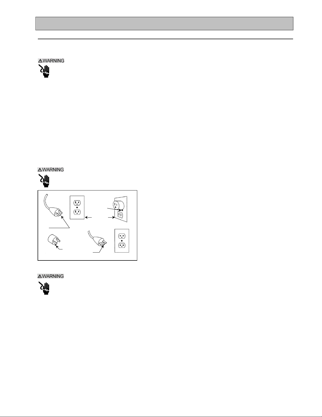
This tool is intended for use on a circuit that has an outlet that looks like the one shown in Sketch A
of Figure 1. The tool has a grounding plug that looks like the plug illustrated in Sketch A of FIGURE
1. A temporary adapter, which looks like the adapter illustrated in sketches B and C, may be used to
connect this plug to a 2-pole receptacle as shown in Sketch B, if a
properly grounded outlet is not available. The temporary adapter
should be used only until a properly grounded outlet can be
installed by a qualified electrician. The green-colored rigid ear,
lug, and the like, extending from the adapter, must be connected
to a permanent ground such as a properly grounded outlet box.
Grounding
(B)
ADAPTER
Grounding
(C)
Grounding
NOTE: Use of a temporary adapter is not permitted in Canada.
FIGURE 1
To reduce the risk of electrocution, keep all connections dry and off the ground.
A Ground Fault Circuit Interrupter (GFCI) should be provided on the circuit(s) or outlet(s) to be used
for the Brick Saw. Receptacles are available having built-in GFCI protections and may be used for
this measure of safety.
When using an extension cord, the GFCI should be installed closest to the power source, followed
by the extension cord and lastly, the saw.
MK-2000 Pro Revision 01/02, Effective Date January 10, 2002
Page 7
Page 8
SAFETY
Tool
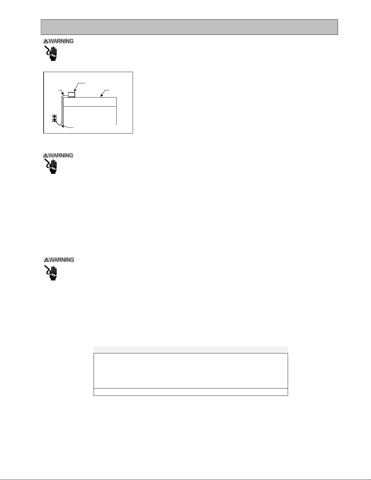
To avoid the possibility of the appliance plug or receptacle getting wet, position the saw to one side
of a wall mounted receptacle. This will prevent water from dripping onto the receptacle or plug. A
"drip loop," shown in FIGURE 2, should be arranged by the user to properly position the power cord
relative to the power source.
Power
Cord
FIGURE 2
Use only extensions cords that are intended for outdoor use. These extension cords are identified
by a marking "Acceptable for use with outdoor appliances; store indoors while not in use." Use only
extension cords having an electrical rating not less than the rating of the product. Do not use
damaged extension cords. Examine extension cords before using and replace if damaged. Do not
abuse extension cords and do not yank on any cord to disconnect. Keep cords away from heat and
sharp edges. Always disconnect the extension cord from the receptacle before disconnection the
product form the extension cord.
Drip Loop
Power
Supporting
Surface
The "drip loop" is that part of the cord below the level of the receptacle, or
the connector, if an extension cord is used. This method of positioning the
cord prevents the travel of water along the power cord and coming in
contact with the receptacle.
If the plug or receptacle gets wet, DO NOT unplug the cord. Disconnect
the fuse or circuit breaker that supplies power to the tool. Then unplug and
examine for presence of water in the receptacle.
To reduce the risk of electrocution, keep all connections dry and off the ground. Do not touch the
plug with wet hands.
Use of undersize extension cords result in low voltage to the motor that can result in motor burnout
and premature failure. MK Diamond warns that equipment returned to us showing signs of being run
in a low voltage condition, through the use of undersized extension cords will be repaired or replaced
totally at the customers’ expense. There will be no warranty claim.
To choose the proper extension cord,
• Locate the length of extension cord needed in TABLE 1 below.
• Once the proper length is found, move down the column to obtain the correct AWG size required
for that length of extension cord.
As an example, a fifty (50) foot extension cord would require an AWG size of 12 for a 115 volt circuit.
Extension Cord Minimum Gage for Length
Volts Total Length of Cord in Feet
25 ft. 50 ft. 100 ft 150 ft.
AWG AWG AWG AWG
115V 14 12 Not Recommended
230V N/A 14 12 N/A
TABLE 1
MK-2000 Pro Revision 01/02, Effective Date January 10, 2002
Page 8
Page 9
SAFETY
SAFETY LABEL LOCATIONS:
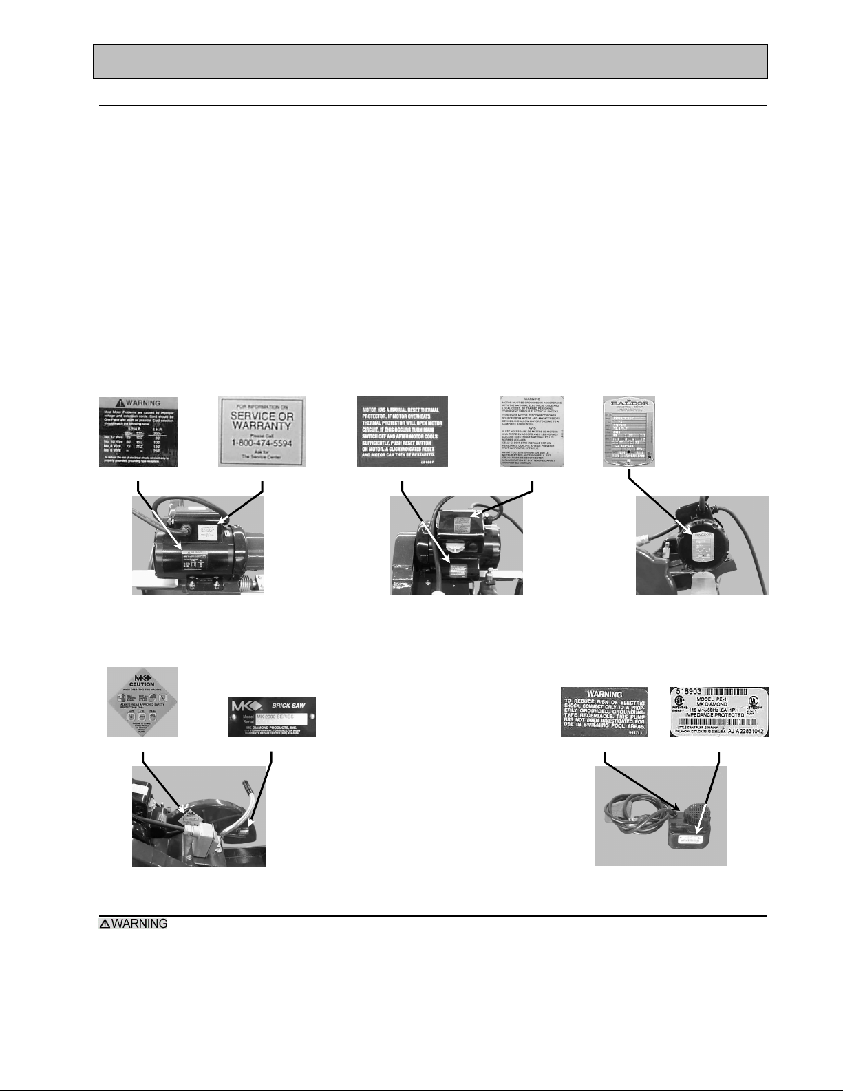
Safety labels are located according to Figures 1 through 5 below. The labels contain important safety
information. Please read the information contained on each safety label. These labels are considered a
permanent part of your saw. If a label comes off or becomes hard to read, contact MK Diamond or your
dealer for a replacement
Item Location Description Part No.
1A. Motor Rear Warning – Extension Cord Information 155672
1B. Motor Rear Service or Warranty Information 155038
2A. Motor Top Thermal Protection Information N/A
2B. Motor Top Motor Grounding Information N/A
3. Motor, Right Side Motor Electrical Information N/A
4A. Blade Guard, Left Side Caution – General Safety Information 155040
4B. Blade Guard, Left Side Saw Serial Number 157007
5A. Pump, Left Side Warning Connect to Grounded Receptacle N/A
5B. Pump, Right Side Pump Specifications N/A
A B
1
A B
A B
2
3
A B
4
5
BRICK SAW SPECIFIC WARNINGS:
Wear eye protection.
Use splash hood for every operation for which it can be used.
Disconnect saw before servicing, when changing cutting blades, and cleaning.
Use tool only with smooth edge cutting blades free of openings and grooves.
Replace damaged cutting blade before operating.
MK-2000 Pro Revision 01/02, Effective Date January 10, 2002
Page 9
Page 10

SAFETY
PRODUCT SPECIFICATIONS:
The MK-2000 Pro is a versatile Brick Saw. Operated and used according to this manual, the MK-2000 Pro
will provide years of dependable service.
General Description:
The MK-2000 Pro Brick Saw is engineered as a portable brick saw powered by either a 2 or 3 horsepower
electric motor. The saw is capable of cutting masonry up to five (5) inches (127 mm) in height, thirty-one (31)
inches (79mm) in length and twenty-three (23) inches (58mm) in width in a single pass.
Motor Specifications:
Motor specifications for the MK-2000 Pro are listed in Table 2 below.
Horse Power 2.0 hp 3.0 hp
Voltage 115 v / 230 v 115 v / 230 v
Overall Amperage 16.8 a / 8.4 a 26.6 a / 13.3 a
Frequency* 60 60
RPM 3450 rpm 3450 rpm
Weight 165 lbs 165 lbs
Table 2
Thermal Overload Protection:
The motor is protected by a thermal overload equipped with a manual reset.
Blade Capacity:
The MK-2000 Pro is designed for use with a 14-inch diameter segmented wet or dry MK Diamond blade with
a .110 to .375 inch cutting width.
Masonry Types:
The MK-2000 Pro can cut a variety of masonry types including, cinder block, slump stone block, wall brick,
paver brick, concrete block and cylinders, roofing tile, marble, granite, decorative rock or almost any other
non-ferrous material.
NOTE:
The MK-2000 Pro is not designed to cut plastic or ferrous (metals) material.
Spring Assisted Cutting Head:
The MK-2000 Pro is designed with a spring-assisted cutting head to allow for easier step cutting. The Cutting
Head can be locked in the down position when cutting smaller pieces.
* The MK-2000 series is also available with a 50hz motor.
MK-2000 Pro Revision 01/02, Effective Date January 10, 2002
Page 10
Page 11
UNPACKING, TRANSPORT, UNIVERSAL STAND and ASSEMBLY
Locked Down
Lift Point
Lift Point
UNPACKING:
Your MK-2000 PRO has been shipped from the factory thoroughly inspected. Only minimal assembly is
required.
Use proper lifting techniques when lifting the MK-2000 PRO.
CONTENTS:
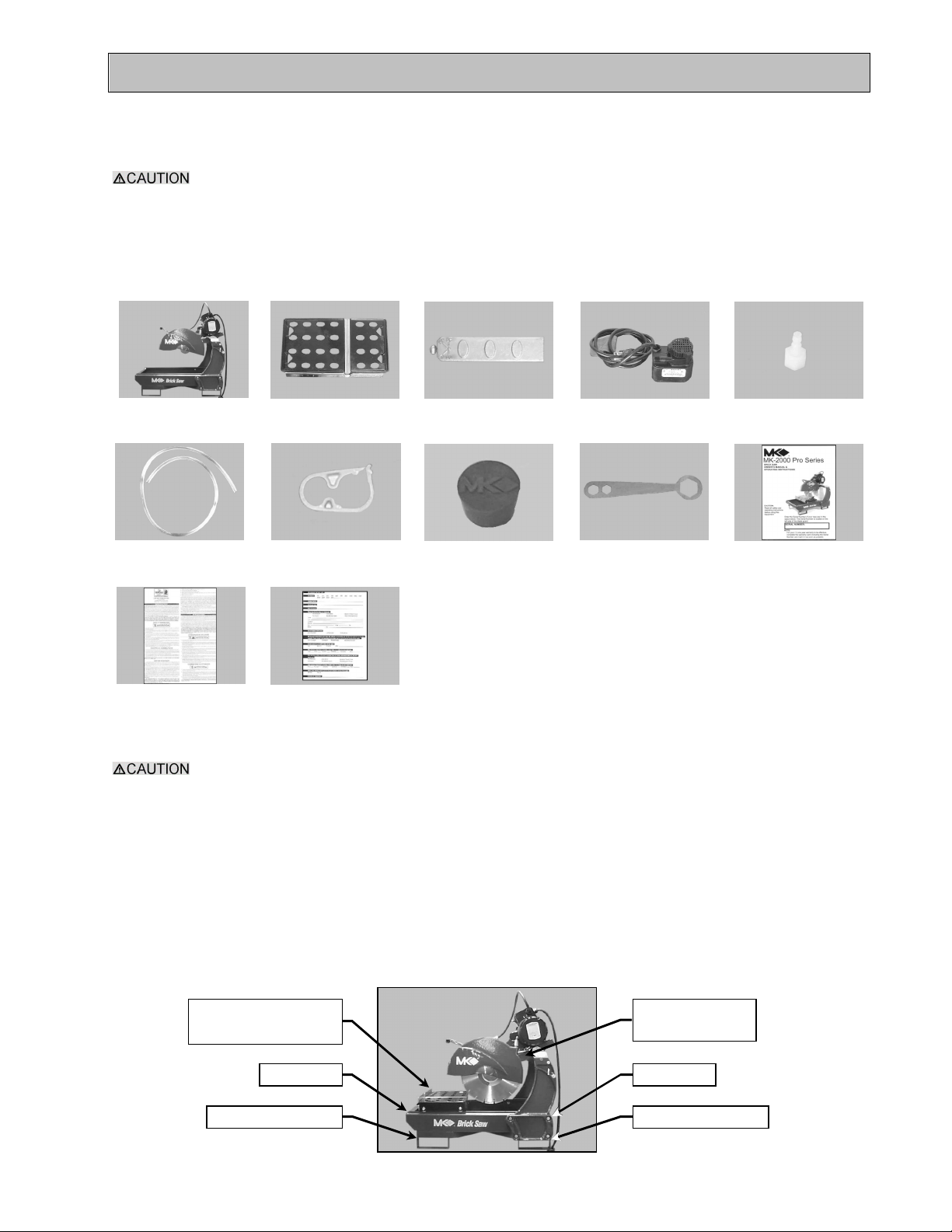
In your container, you will find one (1) MK-2000 PRO, one (1) MK-2000 PRO movable cutting table, one (1)
adjustable cutting guide, one (1) electric water pump, one (1) pump discharge fitting, one (1) cooling transfer
tube, one (1) flow adjusting clamp, one (1) drain plug, one (1) blade wrench, one (1) owners manual, one (1)
pump manual and one (1) warranty card.
MK-2000 PRO Movable
Cutting Table
Cooling
Transfer Tube
Pump
Manual
Flow
Adjusting Clamp
Warranty
Card
Adjustable
Cutting Guide
Drain Plug Wrench Owners
Electric
Water Pump
Pump
Discharge Fitting
Manual
TRANSPORT:
1. The MK-2000 PRO weighs approximately one hundred and sixty-five (165) pounds; use care
when transporting.
2. Never transport the MK-2000 PRO with water in the Water Basin.
NOTE: 1. Lock the Cutting Head in the "DOWN" position and remove the Movable Cutting Table when
transporting the MK-2000 PRO.
2. The MK-2000 Pro is equipped with forklift brackets for in lifting and moving the saw.
The MK-2000 Pro is designed with legs in the front and rear for ease of transport. To transport –
• Verify the Movable Cutting Head is locked in the down position and the Movable Cutting Table is removed
• Position two people on either side of the saw
• From the side, grasp the front and rear of the saw
• Lift and transport the saw to the desired work location
Remove Movable
Cutting Head
Cutting Table
Forklift BracketForklift Bracket
MK-2000 Pro Revision 01/02, Effective Date January 10, 2002 Page 11
Page 12
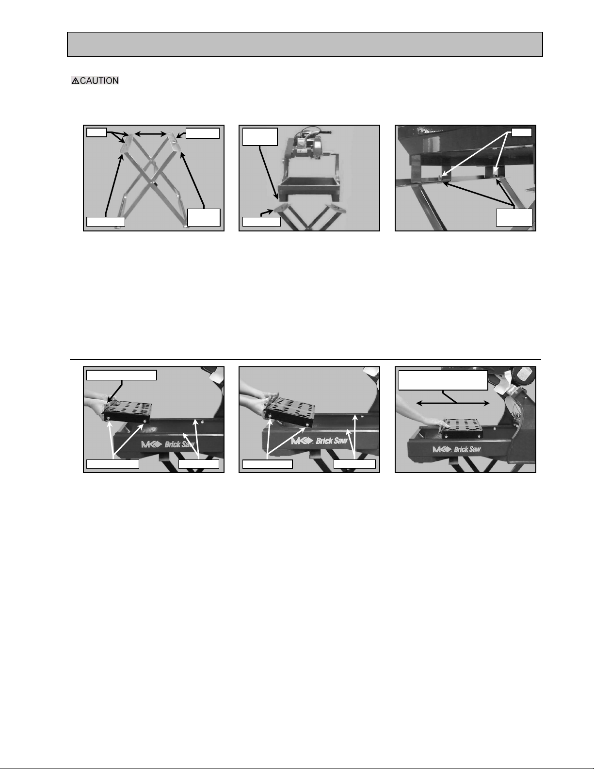
UNPACKING, TRANSPORT, UNIVERSAL STAND and ASSEMBLY
Register side of the Stand
Side
Roller Wheels
Guide Rail
Guide Rails
Roller Wheels
Post
Post Side
Side
Post Side
Posthole
Post
UNIVERSAL STAND:
The MK-2000 PRO weighs one hundred and sixty-five (165) pounds pounds; follow the guidelines
for transport in the TRANSPORT section, when placing it on the stand.
Note: If using the MK Diamond, Universal Stand, follow the following steps.
Register
Register
(A)
Open the Universal Stand and
place it on flat surface then
identify the Post side and
Posthole
(B)
Orient the Saw to the Stand;
ensure the Postholes located on
the two Left Feet of the Saw are
Saw
(C)
Verify the Saw is seated on the
stand with the Stand Posts
through the Saw Postholes
centered above the Stand Posts
ASSEMBLY:
Follow the assembly instructions in this section to prepare your MK-2000 PRO for operation.
1. Movable Cutting Table Installation:
Cutting Table Front
Move back and forth to
verify ease of movement
(A)
While holding the front, position
Movable Cutting Table Roller
Seat Movable Cutting Table
Roller Wheels on Saw Guide
Wheels above Guide Rails
MK-2000 Pro Revision 01/02, Effective Date January 10, 2002
(B)
Rails
(C)
Verify Movable Cutting Table is
seated correctly
Page 12
Page 13
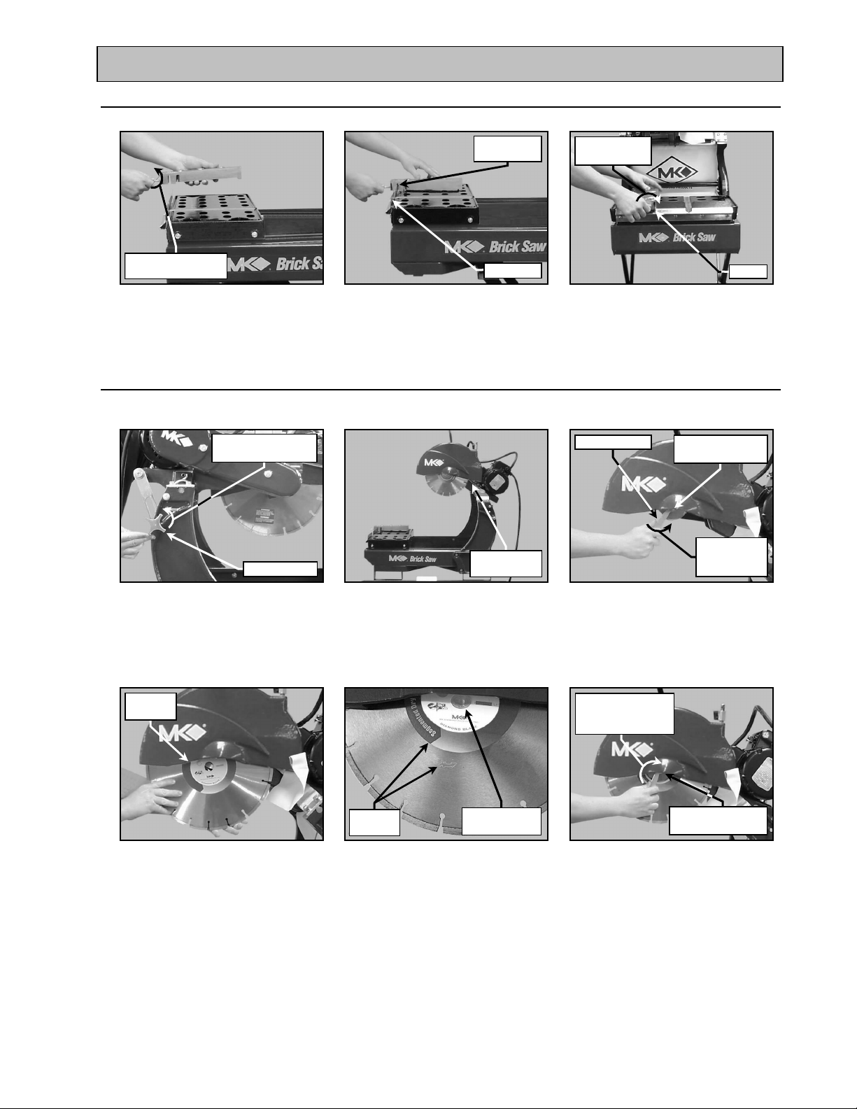
UNPACKING, TRANSPORT, UNIVERSAL STAND and ASSEMBLY
Parallel Slots
clockwise to loosen
loosen
2. Adjustable Cutting Guide Installation:
NOTE: The Adjustable Cutting Guide can be used on either side of the Diamond Blade.
Turn counter-
(A)
Loosen Adjustable Cutting
Guide retaining thumbscrew
Align
Ruler/Stop
(B)
Position Adjustable Cutting
Guide above Movable Cutting
Table
Turn clockwise
to tighten
Seated
(C)
Seat and tighten the Adjustable
Cutting Guide retaining
thumbscrew
4. Diamond Blade Installation:
NOTE: When installing the diamond blade retaining-bolt, ensure the threads of the bolt are aligned with the
threads of the drive shaft so as not to “cross-thread" the bolt.
Turn counter-
clockwise to loosen
Locking Knob
Blade Wrench
Cutting Head
raised
Retaining Screw
and Outer Flange
Turn counter-
clockwise to
(A)
Loosen the Cutting Head
Locking Knob
Install the
Blade
(D)
Install the Diamond Blade onto
Blade Shaft
(B)
Raise Cutting Head to the
highest position and tighten
the Locking Handle
Rotation
Direction
Seat Blade on
Blade Shaft
(E)
Verify the Blade is seated on the
Blade Shaft and the Directional
Arrows are facing out
(C)
Identify and remove Retaining
Screw and Outer Flange using
the Blade Wrench
Rotate the Blade
Wrench clockwise
to tighten
Retaining Screw
and Outer Flange
(F)
Install the Retaining Screw and
Outer Flange and then tighten
MK-2000 Pro Revision 01/02, Effective Date January 10, 2002
Page 13
Page 14
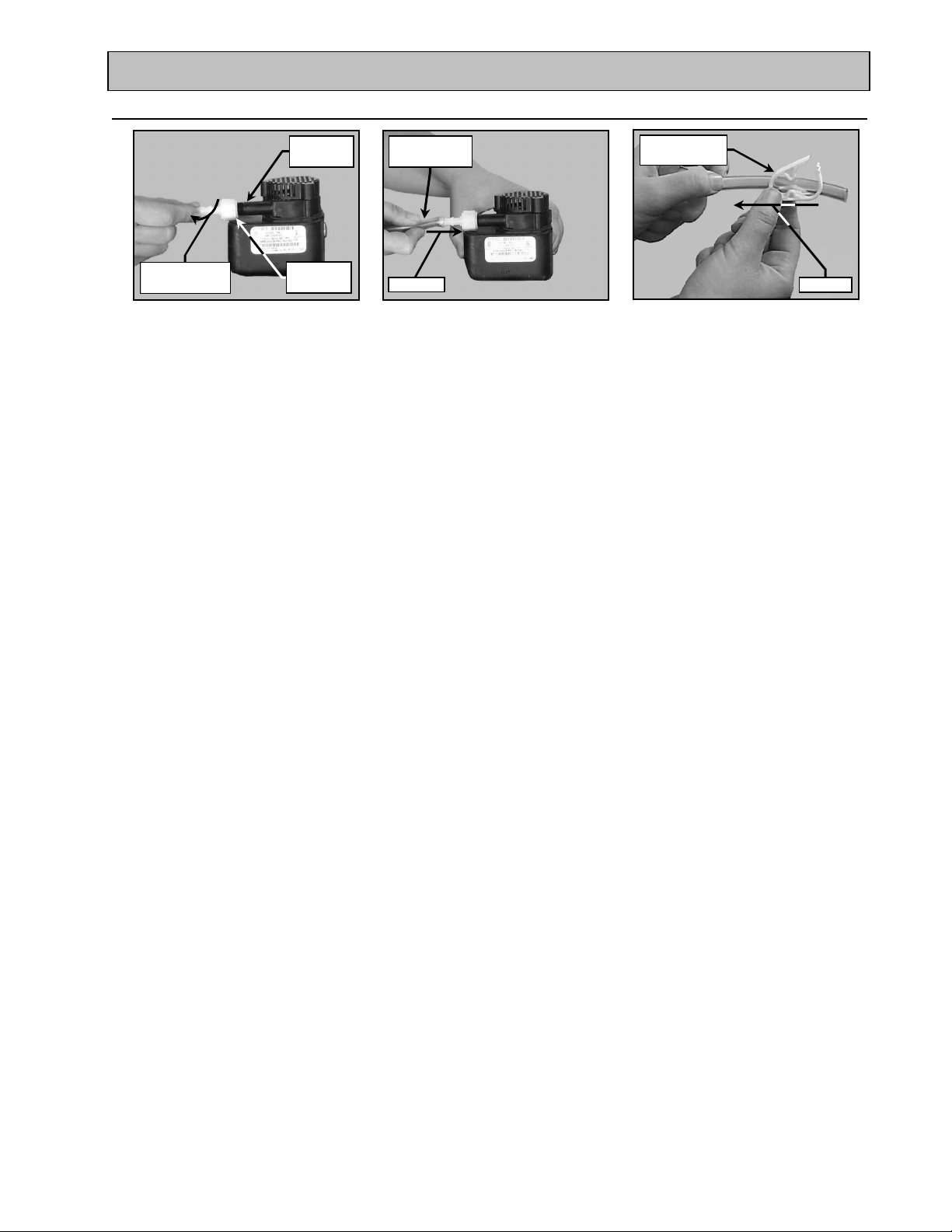
UNPACKING, TRANSPORT, UNIVERSAL STAND and ASSEMBLY
Press on
Press on
5. Water Pump Preparation:
Discharge
Turn clockwise
to tighten
Discharge
(A)
Thread the Water Pump
Discharge Fitting onto the
Water Pump discharge
Pump
Fitting
Cooling
Transfer Tube
(B)
Press one end of the Cooling
Transfer Tube onto the Water
Pump Discharge Fitting
Flow Adjusting
Clamp
(C)
Slide Cooling Flow Adjusting
Clamp onto the Cooling
Transfer Tube
MK-2000 Pro Revision 01/02, Effective Date January 10, 2002
Page 14
Page 15
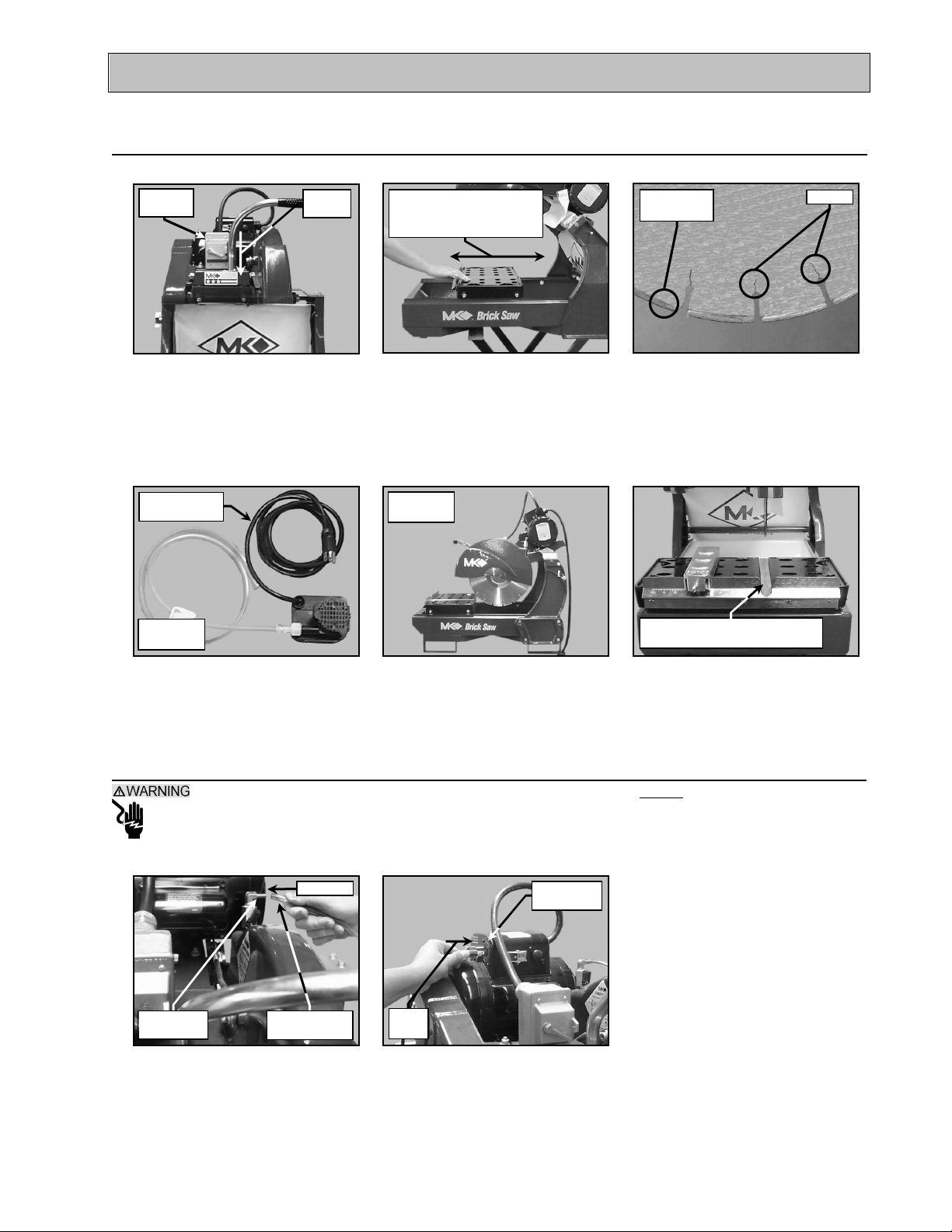
SETUP, ADJUSTMENT and OPERATION
Switch
Cracks
cracks or cuts
Position
Transfer Tube
Press on
Connection
Connection
SETUP:
1. Pre-start Inspection:
Prior to beginning work, a pre-start inspection of the saw should be performed.
ON/OFF
OFF
(A)
Ensure the ON/OFF Switch is
in the OFF position
Inspect for
Inspect for
damage
Verify ease of movement
(See Maintenance section
if problems exist)
(B)
Verify the Movable Cutting
Table moves freely along the
Guide Rails
Inspect for
damage
De-bonding
of segment
(C)
Inspect the Diamond Blade
for damage, cracks and de-
bonding; verify the blade is
correct for the material being cut
Replace if excessively grooved
(See Maintenance Section)
(D)
Inspect the Pump Assembly for
damage – ensure the cord is
free of cracks or cuts
Inspect the MK-2000 PRO for
damage – ensure the cord is
free of cracks or cuts
(E)
(F)
Inspect the Wooden Protective
Strip for excessive grooves
2. Connecting the Water Pump:
1. To prevent the possibility electrical shock, the MK-2000 PRO MUST be de-energized when
connecting the Water Pump.
2. To prevent the possibility of electrical shock, use only MK Diamond qualified replacement parts
NOTE: To prevent pump damage, the Water Pump must be disconnected if cutting with a Dry Blade.
Pump
Inlet
Cooling
(A)
Connect the Cooling Transfer
Tube to the inlet connection of
the Blade Guard
Install
Plug
(B)
Connect the Water Pump
power cord to the connection
found on the back of the motor
MK-2000 Pro Revision 01/02, Effective Date January 10, 2002 Page 15
Page 16
SETUP, ADJUSTMENT and OPERATION
Basin
Suction
Suction
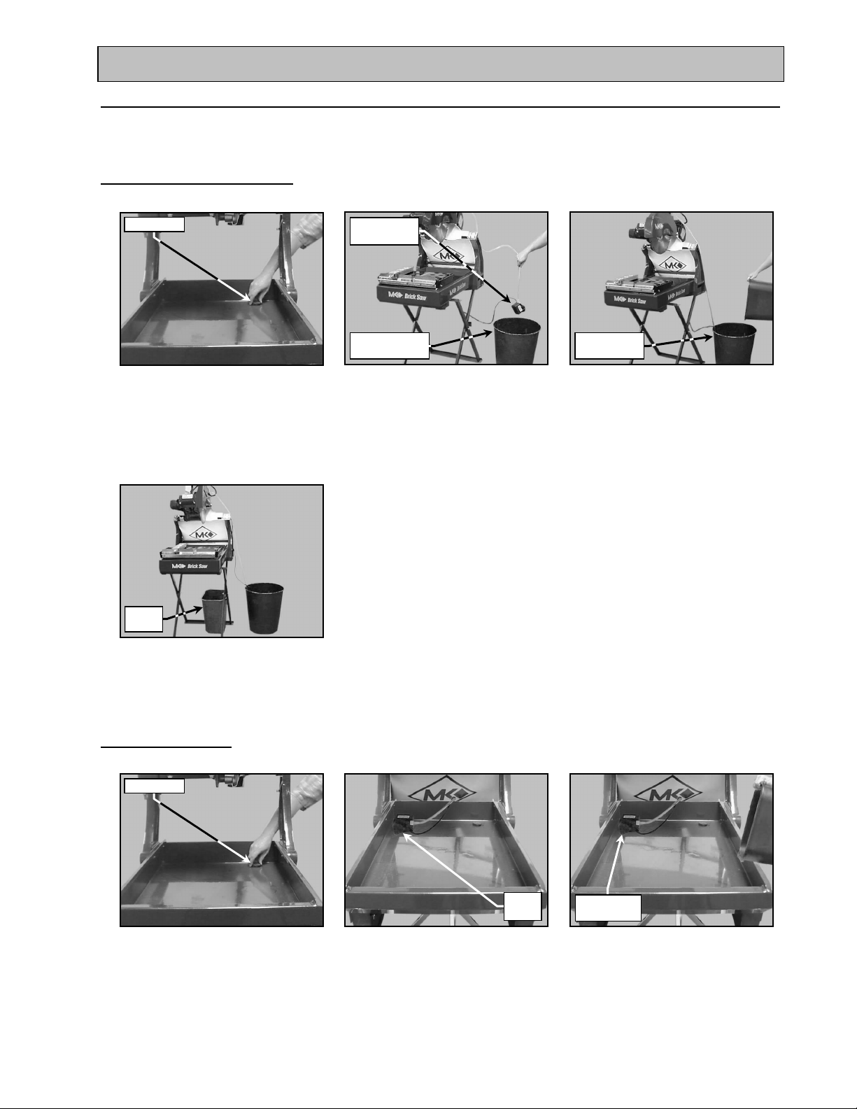
3. Water Pump Setup for Operation:
The Water Pump can be setup for operation in two ways, External Water Source or Re-circulation.
NOTE: If using a dry blade for operation, DO NOT connect the water pump.
I. External Water Source:
This is the preferred method of cooling.
Drain Plug
(A)
Verify or remove the Drain plug
from the Water Pan
Catch
Water Pump
in container
External Water
Container
(B)
Place the Water Pump in an
external container
Cover Pump
(C)
Fill the external container until
water completely covers the
Water Pump suction
(D)
Place an external catch basin
below the Water Pan drain hole
II. Re-circulation:
NOTE: When using the re-circulation method, the water should be changed often for longer pump life.
Drain Plug
Water
Pump
(A)
If not installed, install the Drain
Plug into the Water Pan
MK-2000 Pro Revision 01/02, Effective Date January 10, 2002
Place the Water Pump in the
back of the Water Pan
(B)
Cover Pump
(C)
Fill the Water Pan until water
completely covers the Water
Pump suction
Page 16
Page 17
SETUP, ADJUSTMENT and OPERATION
Source
Source
Switch
Position
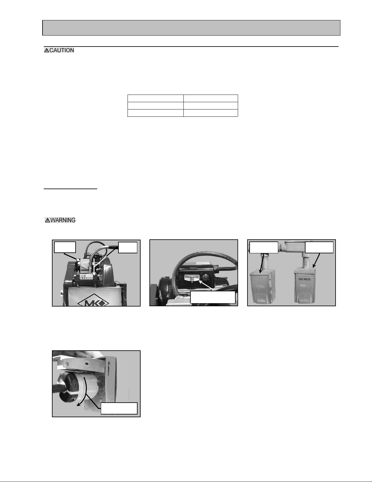
4 MK-2000 PRO Setup for Operation:
1. Before powering or starting, check for damage that could prevent this equipment from proper
operation or performing its intended function. Check for binding and alignment of moving parts.
Check for damaged, broken, or missing parts.
2. Verify the On/Off switch is in the OFF position.
3. Before connecting the MK-2000 PRO to a power supply, be sure the voltage, cycle and phase of
the job site power source meet one of the requirements of TABLE 3
VOLTAGE: 115v/230v
CYCLE: 60hz
PHASE: 1-phase
TABLE 3
4. If using an extension power cord, make sure the length and wire gauge correspond to he
requirements listed in TABLE 1 on page 8. An extension power cord that is too small in wire
gauge (diameter), or too long in length, will cause the motor to overheat and could cause
premature failure.
5. Do not cover the motor vents as this could lead to motor overheating.
NOTE: In order to avoid breaker tripping, a 20-amp circuit breaker should be used.
Portable Generator:
If using a portable generator to provide power, ensure the generator meets the following minimum
requirements:
8 KW 120/240 volts 66.7/33.3 amps Single Phase
The MK-2000 PRO motor has 2 voltage positions, 115v and 240v. Ensure the Voltage Adjustment
Switch of the MK-2000 PRO motor is set for the voltage of the intended power source BEFORE
installing the MK-2000 PRO Power cord.
ON/OFF
OFF
(A)
Ensure the ON/OFF Switch is
in the OFF position
Voltage Adjustment
Switch
(B)
Verify or place the Voltage
Adjustment Switch in the correct
voltage position (See the
Maintenance Section)
115v Power
240v Power
(C)
Locate the correct power source
for the setting of the MK-2000
PRO Voltage Adjustment Switch
Turn clockwise
to lock
(D)
Align, install and twist to lock the
Polarized plug of the MK-2000
PRO into the correct power
MK-2000 Pro Revision 01/02, Effective Date January 10, 2002
Page 17
Page 18
SETUP, ADJUSTMENT and OPERATION
Switch
Points
the Piece toward the Blade
Table
Stroke
"Pull" Stroke
Table
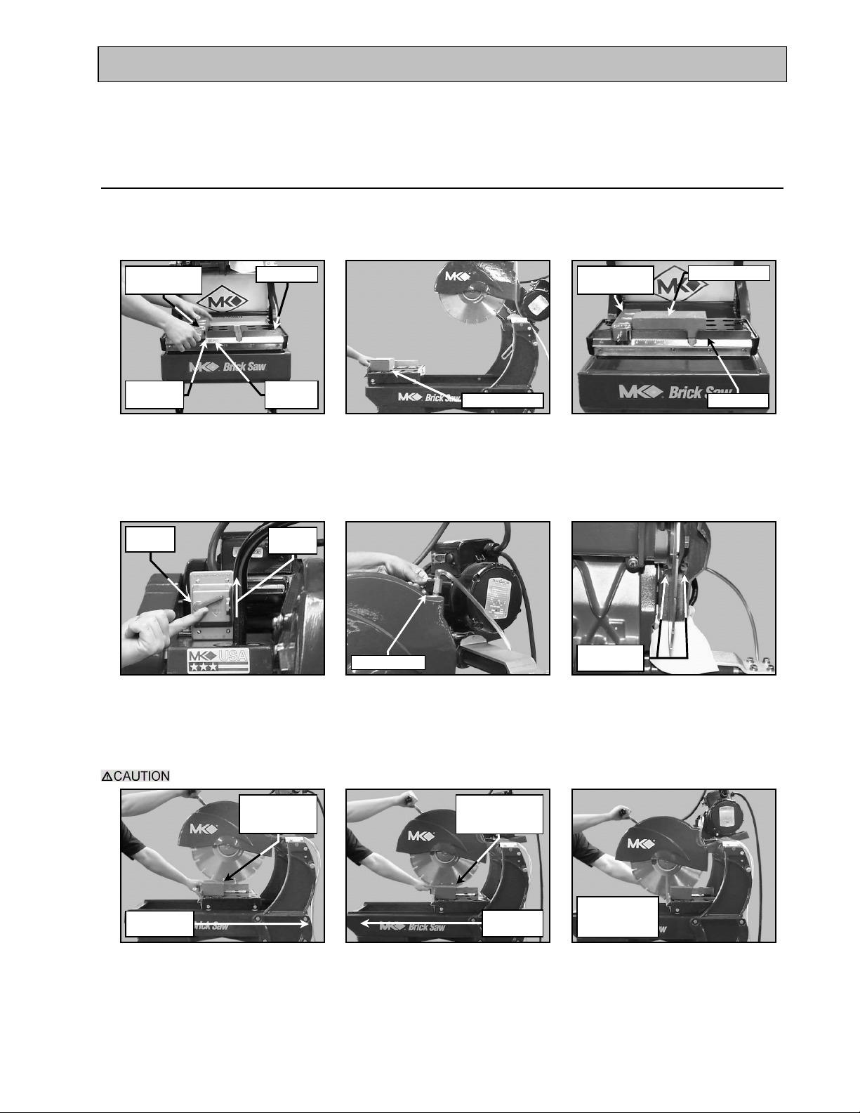
ADJUSTMENT and OPERATION:
NOTE: 1. Step Cutting is the preferred cutting method for all cuts.
2. When cutting hard material Step Cutting should always be used.
3. Step Cutting will extend the life of the Diamond Blade.
1. Step Cuts:
A Step Cut is performed when a series of small cuts of increasing depth are used to complete a single cut.
Step Cuts are used for large objects or for hard objects such as Firebrick and Pavers.
Note: Skip steps E and F, if cutting dry.
Adjustable
Cutting Guide
Measuring
point
Ruler/Stop
Ruler
Markings
(A)
Set the Adjustable Cutting Guide
to the desired length indicated
on the side of the Ruler/Stop
closest to the Wooden Strip
ON/OFF
OFF
Position
Masonry Piece
(B)
Place the Masonry Piece onto
the Movable Cutting Table
Control Valve
Cutting Guide
Masonry PieceAdjustable
Ruler/Stop
(C)
Verify the Masonry Piece is
seated against the Ruler/Stop
and the Adjustable Cutting Guide
Cooling Flow
(D)
Place the ON/OFF Switch in
the ON position
Open the Cooling Flow Control
Valve and adjust cooling flow
(E)
Cut in smooth even strokes; do not force the saw to cut.
Lower 1/4 -1/2
inch for "Push"
Push Cutting
(G)
Hold the Masonry Piece, lower
the Cutting Head and "Push"
Once the "Push" cut is
complete, lower the Cutting
Lower additional
1/4 -1/2 inch for
Pull Cutting
(H)
Head further and "Pull" the
Piece forward into the Blade
MK-2000 Pro Revision 01/02, Effective Date January 10, 2002
(F)
Verify cooling flow exists on
both sides of the blade
Continue Steps
"G" and "H" to
complete cut
(I)
Repeat steps G and H until
cutting is complete
Page 18
Page 19
SETUP, ADJUSTMENT and OPERATION
Switch
Position
Switch
Points
ON/OFF
OFF
(J)
Turn the Saw off when cutting
is complete
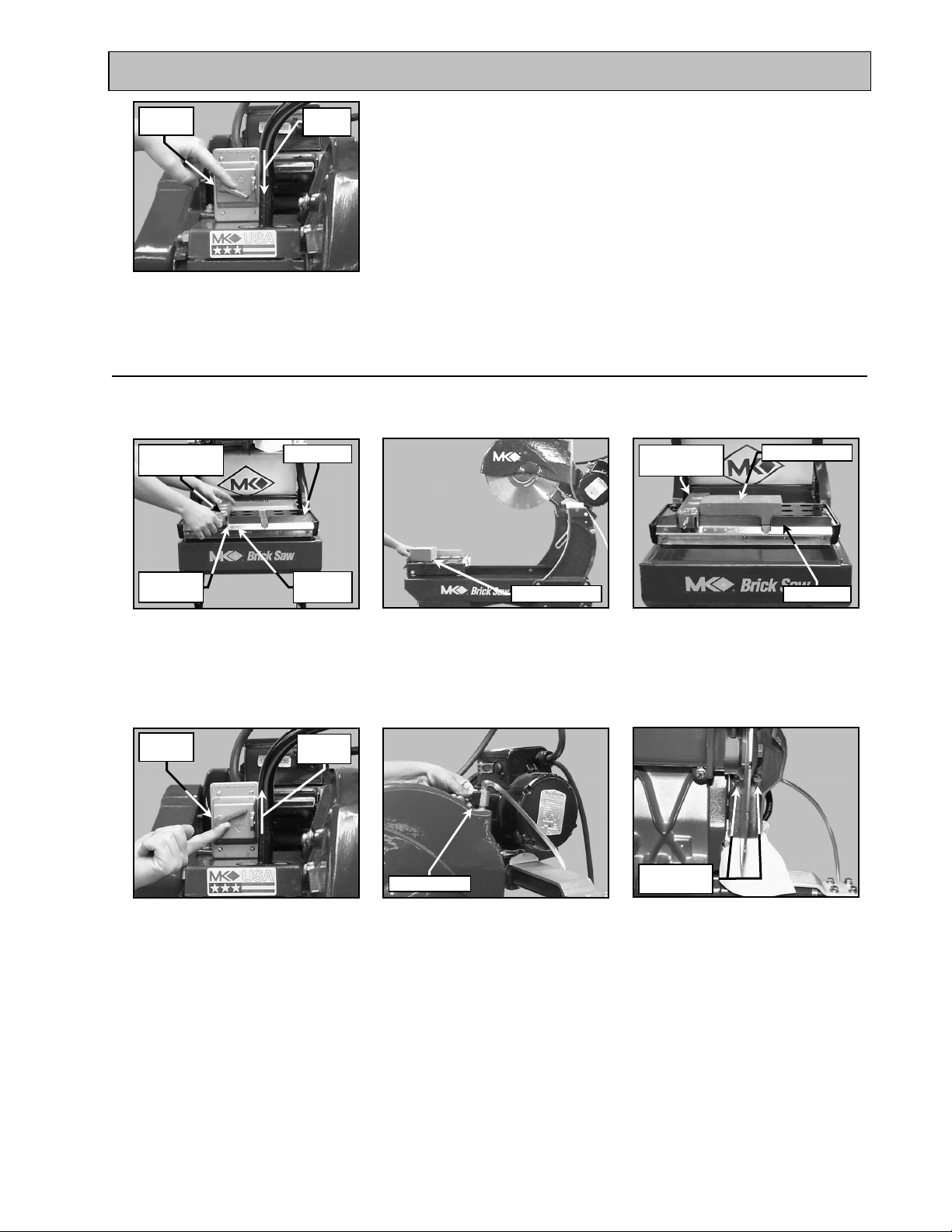
2. Chop Cutting:
A Chop Cut is performed by cutting completely through an object in one pass.
Note: Skip steps E and F, if cutting dry.
Adjustable
Cutting Guide
Ruler/Stop
Cutting Guide
Masonry PieceAdjustable
Measuring
point
Ruler
Markings
(A)
Set the Adjustable Cutting Guide
to the desired length indicated
on the side of the Ruler/Stop
closest to the Wooden Strip
ON/OFF
OFF
Position
(D)
Place the ON/OFF Switch in
the ON position
Masonry Piece
(B)
Place the Masonry Piece onto
the Movable Cutting Table
Control Valve
(E)
Open the Cooling Flow Control
Valve and adjust cooling flow
Ruler/Stop
(C)
Verify the Masonry Piece is
seated against the Ruler/Stop
and the Adjustable Cutting Guide
Cooling Flow
(F)
Verify cooling flow exists on
both sides of the blade
MK-2000 Pro Revision 01/02, Effective Date January 10, 2002
Page 19
Page 20
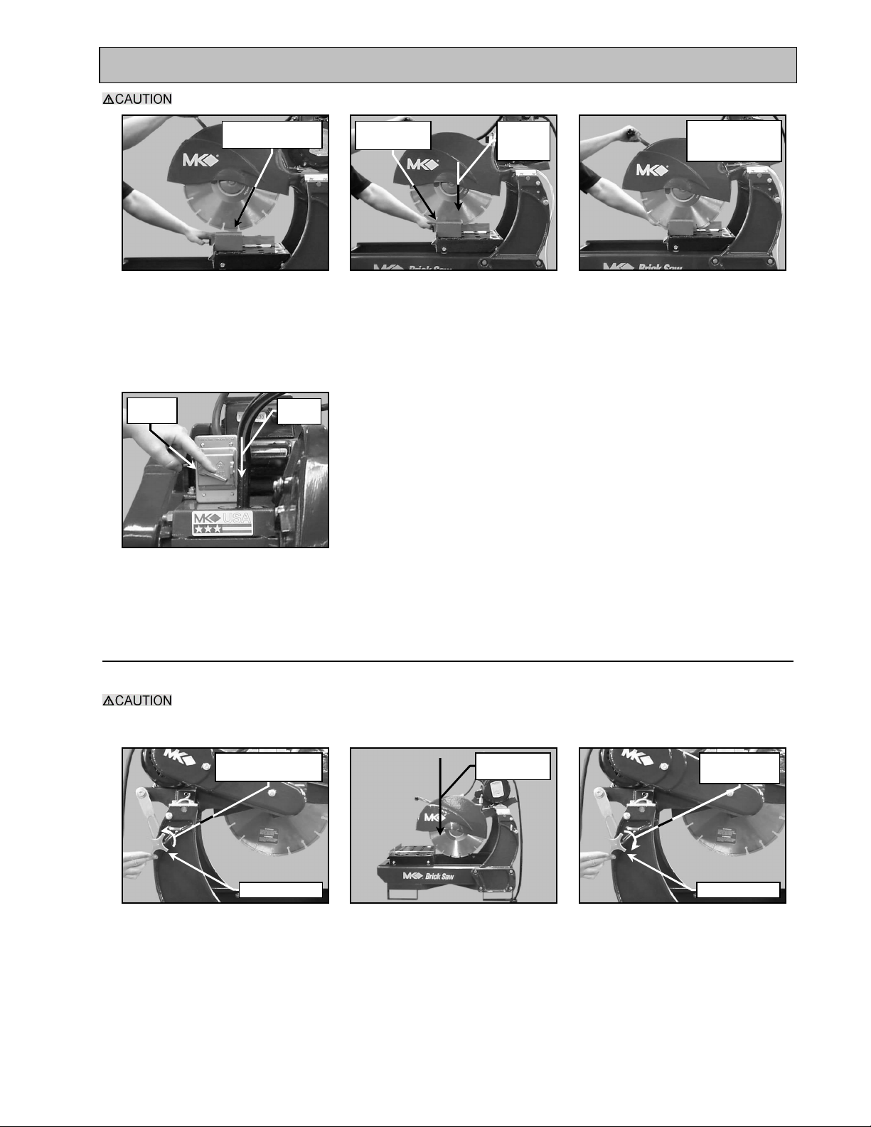
SETUP, ADJUSTMENT and OPERATION
to Cut
Switch
Position
Cut in smooth even strokes; do not force the saw to cut.
Position Masonry
Piece below Blade
(G)
Position the Masonry Piece
below the Blade
ON/OFF
OFF
Hold Masonry
Stationery
(H)
Lower the Cutting Head to
begin the cut
Lower
Smoothly
Continue to Lower
Cutting Head until
Cut Complete
(J)
Continue lowering the Cutting
Head until the cut is complete
raise the cutting head when
the cut is complete
(K)
Turn the Saw off when cutting
is complete
3. Cutting with the Cutting Head Locked Down:
This method is preferred when cutting small objects.
Cut in smooth even strokes; do not force the saw to cut.
Note: Skip steps H and I, if cutting dry.
Turn counter-
clockwise to loosen
Locking Handle
(A)
If locked, loosen the Cutting
Head Locking Knob
Lower the Cutting Head until the
Blade touches the Protective
Wooden Strip
(B)
Lower Cutting
Head
Turn clockwise
to tighten
Locking Handle
(C)
Lock the Cutting Head in the
"Down" position using the
Locking Knob
MK-2000 Pro Revision 01/02, Effective Date January 10, 2002
Page 20
Page 21
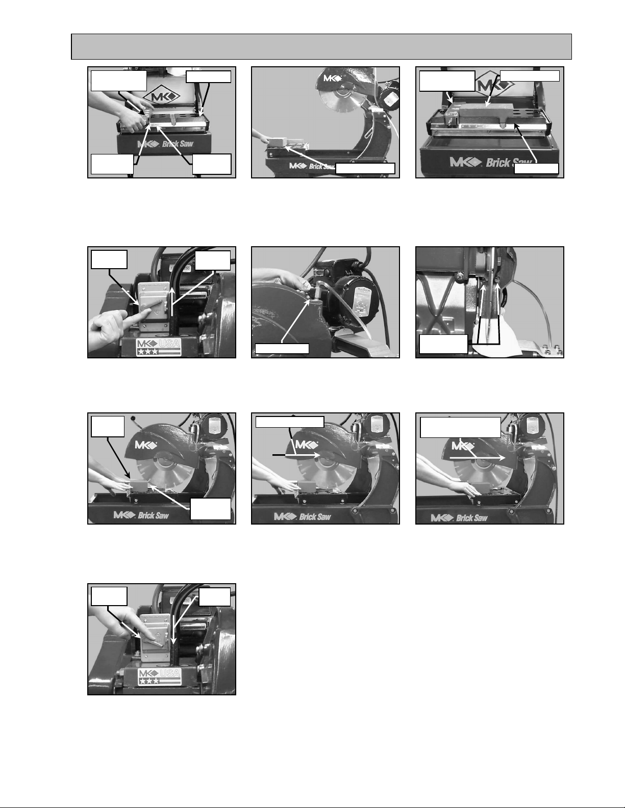
SETUP, ADJUSTMENT and OPERATION
Switch
Points
cut is complete
Switch
Position
Adjustable
Cutting Guide
Measuring
point
Ruler/Stop
Ruler
Markings
(D)
Set the Adjustable Cutting Guide
to the desired length indicated
on the side of the Ruler/Stop
closest to the Wooden Strip
ON/OFF
OFF
Position
(G)
Place the ON/OFF Switch in
the ON position
Masonry Piece
(E)
Place the Masonry Piece onto
the Movable Cutting Table
Control Valve
(H)
Open the Cooling Flow Control
Valve and adjust cooling flow
Cutting Guide
Masonry PieceAdjustable
Ruler/Stop
(F)
Verify the Masonry Piece is
seated against the Ruler/Stop
and the Adjustable Cutting Guide
Cooling Flow
(I)
Verify cooling flow exists on
both sides of the blade
Hold in
position
Move into
position
(J)
Move the Cutting Table to
position the Masonry Piece in
front of the Blade
ON/OFF
OFF
(M)
Turn the Saw off when cutting
is complete
Push slowly to cut
(K)
Slowly push piece into the
blade until cutting begins
Continue pushing
until cutting complete
(L)
Continue to push the Masonry
Piece into the Blade until the
MK-2000 Pro Revision 01/02, Effective Date January 10, 2002
Page 21
Page 22
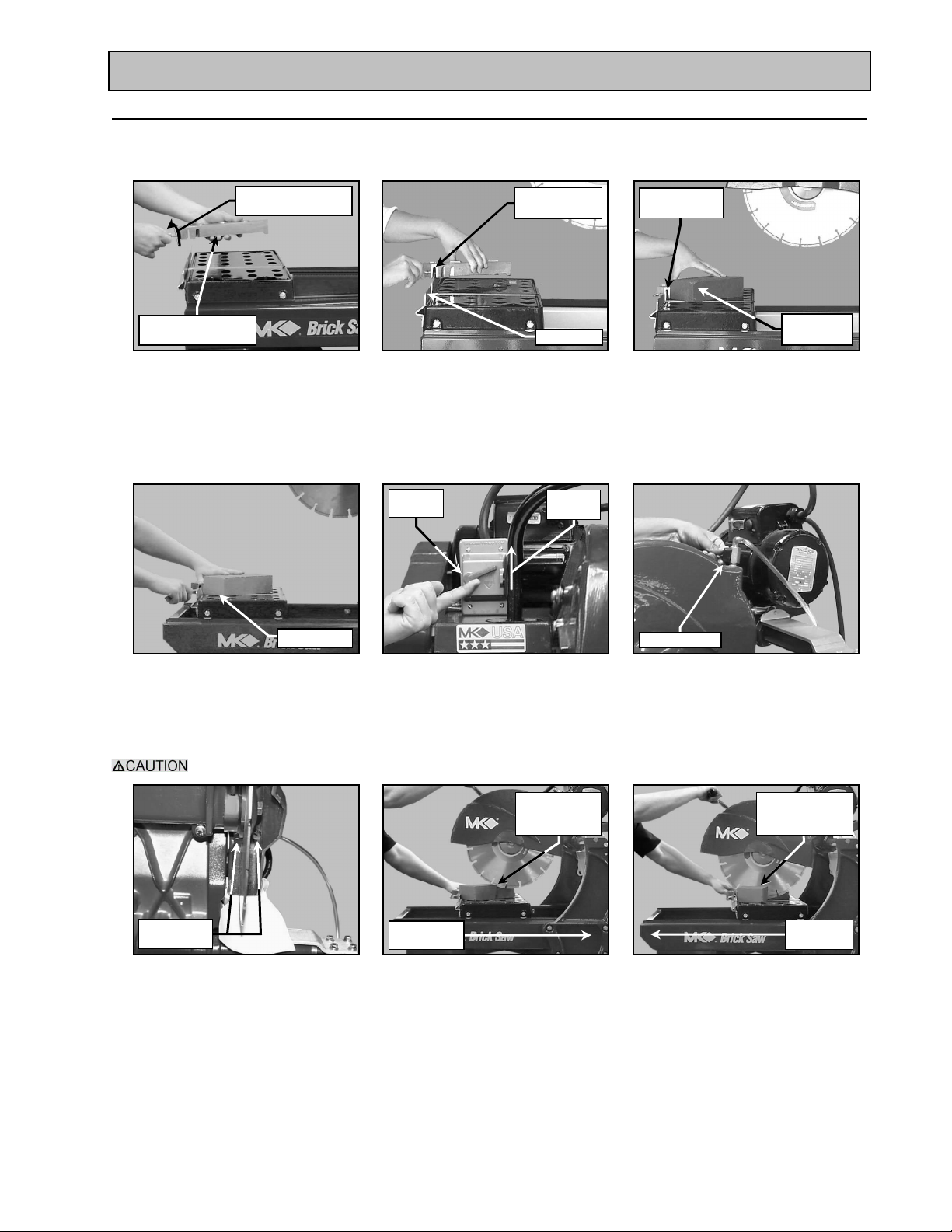
SETUP, ADJUSTMENT and OPERATION
Switch
Points
the Piece toward the Blade
Table
Stroke
"Pull" Stroke
Table
clockwise to loosen
4. Angle Cuts:
Angle Cuts may be performed using any cutting method. The following example uses the Step Cut method.
Note: Skip steps F and G, if cutting dry.
Turn counter-
Remove Adjustable
Cutting Guide
(A)
Remove the Adjustable
Cutting Guide
Setup to cut
Align 45° Slots
to Ruler/Stop
Ruler/Stop
(B)
Reposition the Adjustable Cutting
Guide to the 45° cutting position
ON/OFF
OFF
Position
Adjustable
Cutting Guide
Place Work
in position
(C)
Position Masonry Piece against
the Adjustable Cutting Guide
Control Valve
(D)
Position the Masonry Piece
and Adjustable Cutting Guide
to the desired cut length
Cut in smooth even strokes; do not force the saw to cut.
Cooling Flow
(G)
Verify cooling flow exists on
both sides of the blade
(E)
Place the ON/OFF Switch in
the ON position
Lower 1/4 -1/2
inch for "Push"
Push Cutting
(H)
Hold the Masonry Piece, lower
the Cutting Head and "Push"
(F)
Open the Cooling Flow Control
Valve and adjust cooling flow
Lower additional
1/4 -1/2 inch for
Pull Cutting
(I)
Once the "Push" cut is
complete, lower the Cutting
Head further and "Pull" the
Piece forward into the Blade
MK-2000 Pro Revision 01/02, Effective Date January 10, 2002
Page 22
Page 23
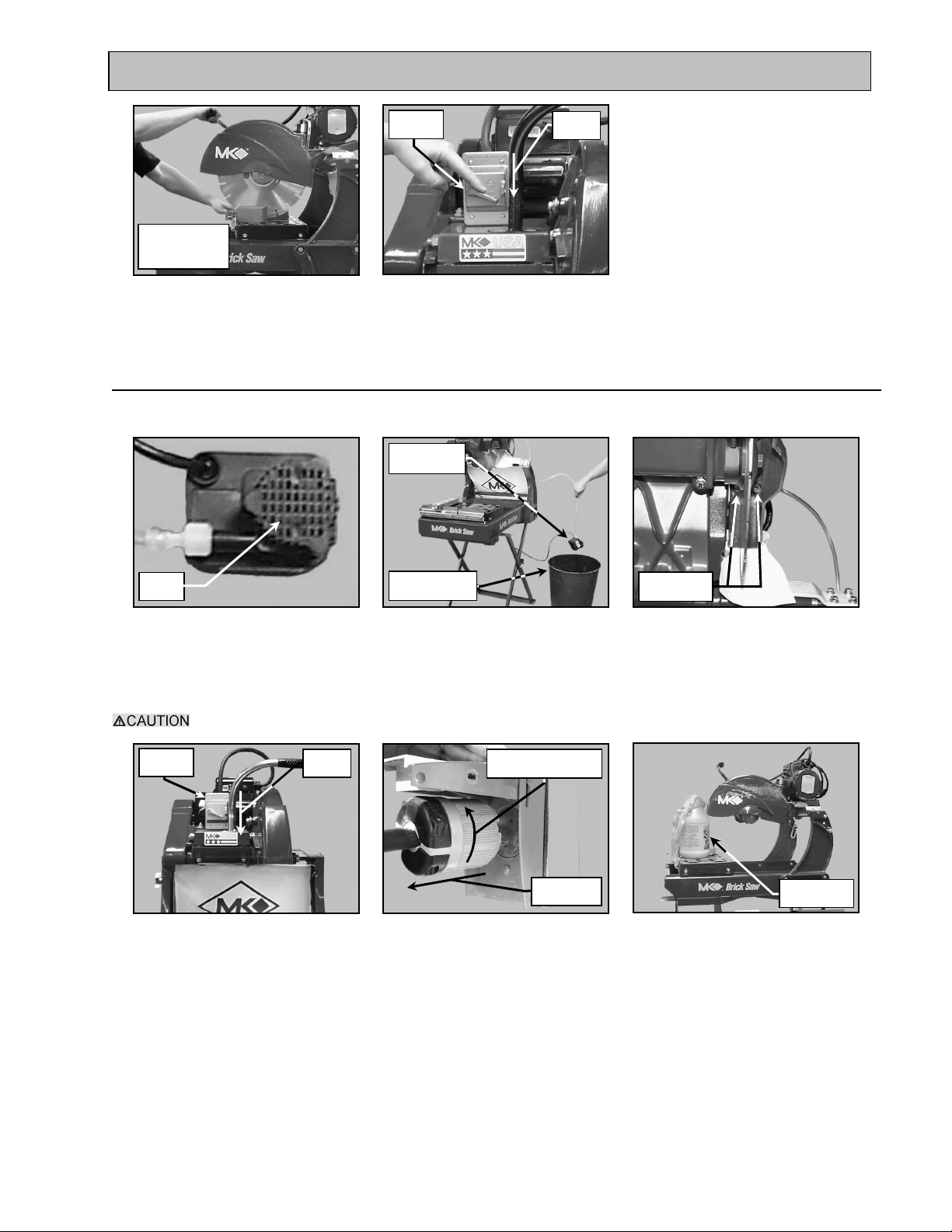
SETUP, ADJUSTMENT and OPERATION
Suction
Switch
Position
Points
clockwise to unlock
back
Fresh Water
Switch
Position
Continue Steps
"H" and "I" to
complete cut
(J)
Repeat steps H and I until
cutting is complete
ON/OFF
(K)
Turn the Saw off when cutting
is complete
OFF
5. Cleanup:
NOTES: 1. If an external water source was used, steps A through C may be skipped.
2. Dispose of wastewater in accordance with applicable Federal, State and Local laws.
Water Pump
in container
Pump
(A)
Clean the Water Pump suction
of all debris
Ensure the saw is disconnected before completing the remainder of the cleanup process.
ON/OFF
OFF
(D)
Ensure the ON/OFF Switch is
in the OFF position
External Water
Container
(B)
Place the Water Pump in an
external container
Turn counter-
Pull straight
(E)
Unplug the MK-2000 PRO
Polarized plug from the power
source by turning counterclockwise and then pulling
straight back
Cooling Flow
(C)
Run the MK-2000 PRO until
clear water is seen at the Blade
cooling ports (Approx. 1 minute)
Soap and
(F)
Clean the MK-2000 PRO with
soap and clean water
MK-2000 Pro Revision 01/02, Effective Date January 10, 2002
Page 23
Page 24
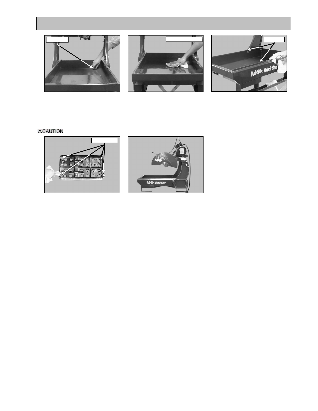
SETUP, ADJUSTMENT and OPERATION
for disposal)
Roller Wheel
Drain Plug
(H)
Remove Drain Plug and
dispose of water (conform to
Federal, State and local laws
Ensure water is not forced into the motor casing when cleaning.
Clean Water Basin
(I)
Clean Water Basin with soap
and clean water
Guide Rail
(J)
Clean the Movable Cutting
Table Guide Rails
(K)
Clean the Movable Cutting
Table Roller Wheels
(L)
Clean the remainder of the
MK-2000 PRO
MK-2000 Pro Revision 01/02, Effective Date January 10, 2002
Page 24
Page 25
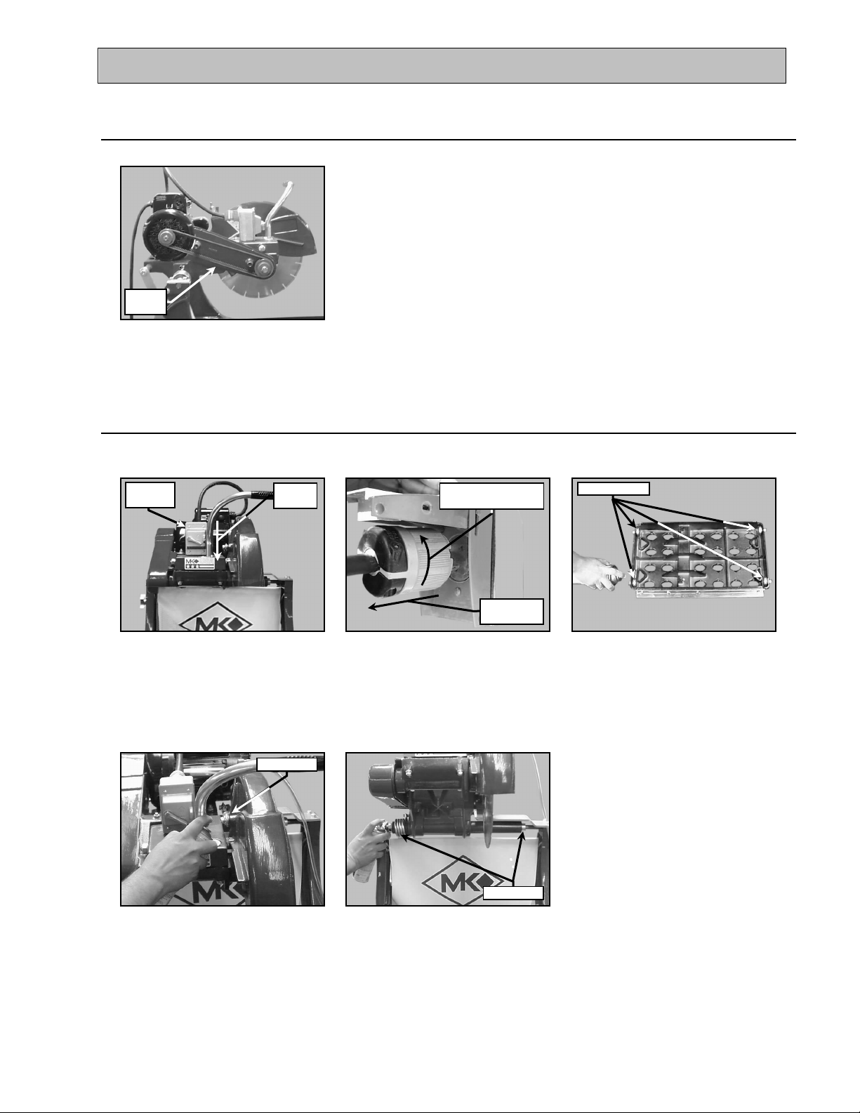
MAINTENANCE AND TROUBLESHOOTING
straight back
clockwise to unlock
back
Roller Wheel
Pivot Point
Pivot Point
V-belt
Switch
Position
MAINTENANCE:
1. New Maintenance:
Perform the following after initial purchase and operation of the MK-2000 PRO.
Inspect
(A)
Check and adjust V-belt tension
following the first 48 hours of
operation (See V-belt Inspection)
2. Maintenance Following Use:
To extend the life of the MK-2000 PRO, the following procedure should be performed after each use.
Lubricate all points listed below with light oils such as, 3 in 1, WD-40, etc.
ON/OFF
OFF
(A)
Ensure the ON/OFF Switch is
in the OFF position
Turn counter-
Pull straight
(B)
Unplug the MK-2000 PRO
Polarized plug from the power
source by turning counterclockwise and then pulling
(C)
Lubricate the Movable Cutting
Table Roller Wheels
(D)
Lubricate the Blade Guard
Lubricate the Cutting Head
Pivot Points
MK-2000 Pro Revision 01/02, Effective Date January 10, 2002 Page 25
(E)
Pivot Points
Page 26
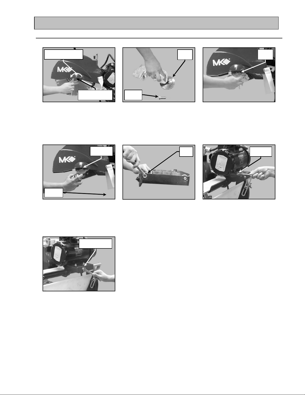
MAINTENANCE AND TROUBLESHOOTING
Screw Hole
Screw
3. Monthly Maintenance:
The following maintenance should be performed monthly.
Rotate counter-
clockwise to loosen
Retaining Screw
and Outer Flange
(A)
Remove the Diamond Blade
Retaining
Retaining
Flange
Retaining
Screw
(B)
Clean the Outer Flange and
Retaining Screw
Outer
Verify
Tight
Inner
Flange
(C)
Clean the Inner Flange
Verify Four
Bolts Tight
(D)
Lubricate the Retaining Screw
and Retaining Screw Hole
Verify Adjustment
Strap Tight
(G)
Verify the Motor Adjustment
Strap is tight
(E)
Verify the Movable Cutting
Table Roller Wheels are tight
and in good condition
(F)
Verify all motor mounting Bolts
are tight
MK-2000 Pro Revision 01/02, Effective Date January 10, 2002
Page 26
Page 27
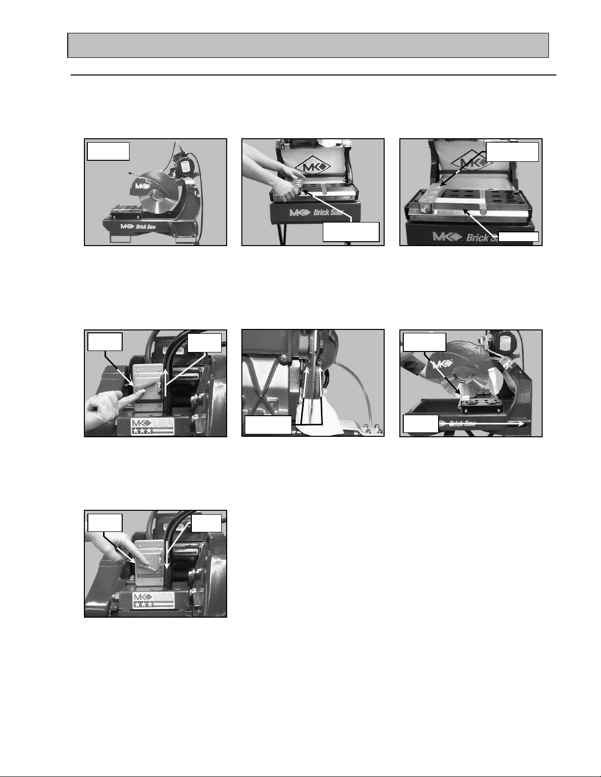
MAINTENANCE AND TROUBLESHOOTING
Operation
Switch
Points
Switch
Position
of Cut
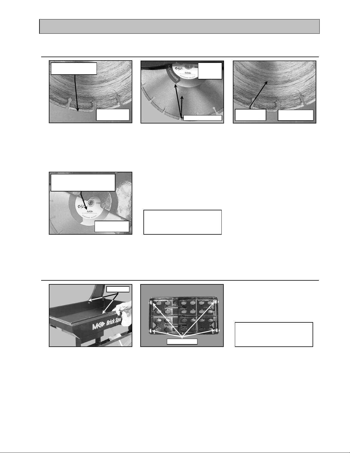
4. Blade Dressing:
Like most cutting instruments, a diamond blade performs best when it is dressed. Over time and use,
diamonds on the outer edge of the blade will become smoothed or “glazed” over. This will reduce grinding
efficiency and may cause the blade to “wander” or bend giving the illusion of an alignment problem. When
this occurs, the blade will need to be dressed. The diamond blade can be dressed using the MK Dressing
Stick (part number 152972) and by following the steps below.
Setup for
(A)
Setup the MK-2000 PRO for
operation (See Setup,
Adjustment and Operation
ON/OFF
OFF
Position
Set Adjustable
Cutting Guide
(B)
Set the Adjustable Cutting
Guide to cut a 1/16-strip
Cooling Flow
Adjustable
Cutting Guide
Ruler/Stop
(C)
Position the Dressing Stick
against the Adjustable Cutting
Guide and the Ruler/Stop
Hold Work
in Position
Direction
(D)
Place the ON/OFF Switch in
the ON position
ON/OFF
OFF
(G)
Turn the Saw off when cutting
is complete
(E)
Verify cooling flow exists on
both sides of the blade
(F)
Cut the Dressing Stick 7 or 8
times to dress the Blade
MK-2000 Pro Revision 01/02, Effective Date January 10, 2002
Page 27
Page 28
MAINTENANCE AND TROUBLESHOOTING
loosen
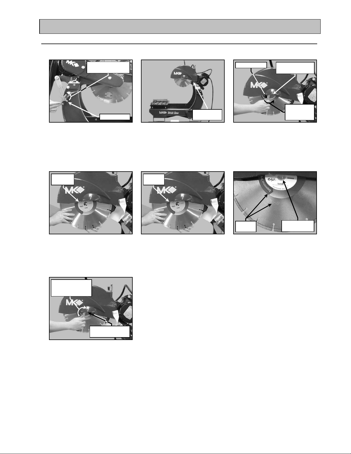
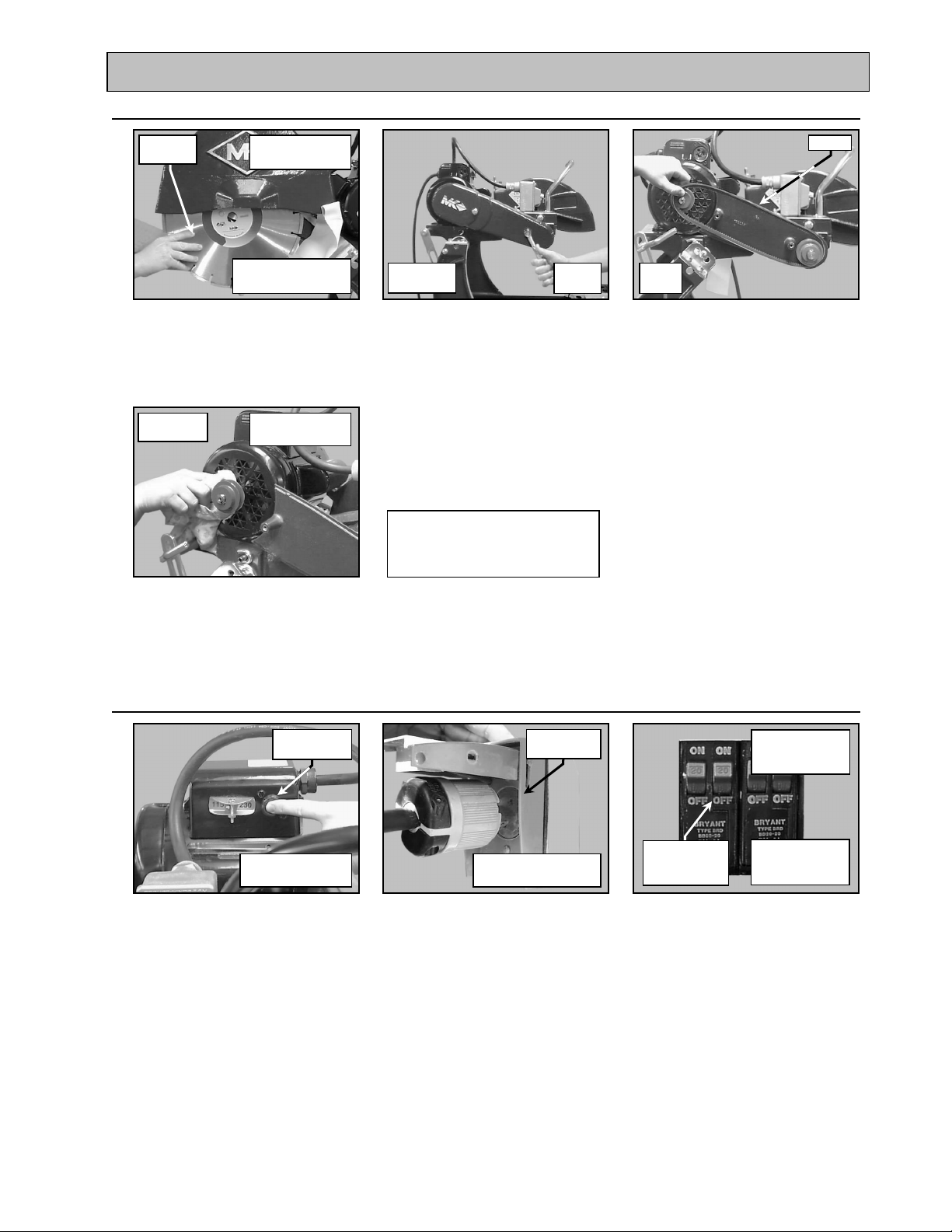
5. Diamond Blade Change-out:
NOTE: When installing the diamond blade retaining-bolt, ensure the threads of the bolt are aligned with the
threads of the drive shaft so as not to “cross-thread" the bolt.
Turn counter-
clockwise to loosen
Locking Knob
(A)
Loosen the Cutting Head
Locking Handle
Remove
the Blade
Cutting Head
raised
(B)
Raise Cutting Head to the
highest position and tighten the
Locking Handle
Install the
Blade
Blade Wrench
Retaining Screw
and Outer Flange
Turn counter-
clockwise to
(C)
Identify and remove Retaining
Screw and Outer Flange using
the Blade Wrench
Rotation
Direction
Seat Blade on
Blade Shaft
(D)
Remove the old Diamond Blade
Rotate the Blade
Wrench clockwise
to tighten
Retaining Screw
and Outer Flange
(G)
Install the Retaining Screw and
Outer Flange and then tighten
(E)
Install the new Diamond Blade
onto Blade Shaft
(F)
Verify the Blade is seated on the
Blade Shaft and the Directional
Arrows are facing out
MK-2000 Pro Revision 01/02, Effective Date January 10, 2002
Page 28
Page 29
MAINTENANCE AND TROUBLESHOOTING
Roller Wheels
Clean Holes
1/2-Inch Wrench
Washer
Roller Wheel
1/2-Inch Wrench
clockwise to loosen
Roller Wheels
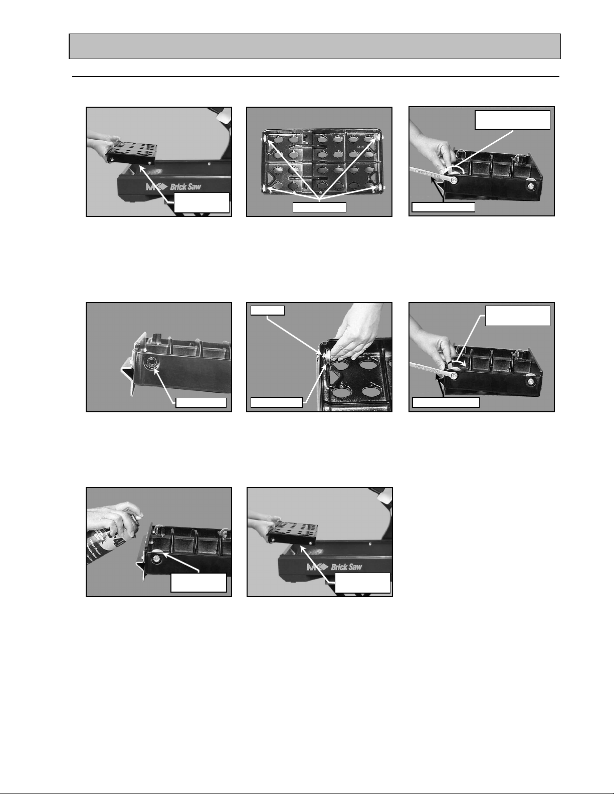
6. Movable Cutting Table Wheel Change Out:
NOTE: All four (4) Movable Cutting Table, Roller Wheels should be replaced at the same time (MK Diamond
Part No. – 133090)
Rotate counter-
Movable
Cutting Table
(A)
Remove the Movable Cutting
Table
(D)
Clean the Roller Wheel Shaft
Holes in the Movable Cutting
Table before installing new
Roller Wheels
(B)
Place the Movable Cutting
Table on a Workbench with the
Roller Wheels facing up
(E)
Install the Wheel/Washer
Assembly into Movable Cutting
Table Wheel Shaft Hole
(C)
Using a 1/2-inch wrench, remove
the Roller Wheel Retaining Nut
and the Roller Wheel
Rotate clockwise
to tighten
(F)
Install the Roller Wheel
Retaining Nut and tighten using
a 1/2-inch wrench
Lubricate
(G)
Lubricate the Roller Wheels
using light oil
(H)
Remove the Movable Cutting
Table
Movable
Cutting Table
(Such as WD-40, 3 in 1, etc.)
MK-2000 Pro Revision 01/02, Effective Date January 10, 2002
Page 29
Page 30
MAINTENANCE AND TROUBLESHOOTING
Roller Wheels
Screwdriver
Screwdriver
the Retaining Screws
Screwdriver
Screw
Move Switch
Screw
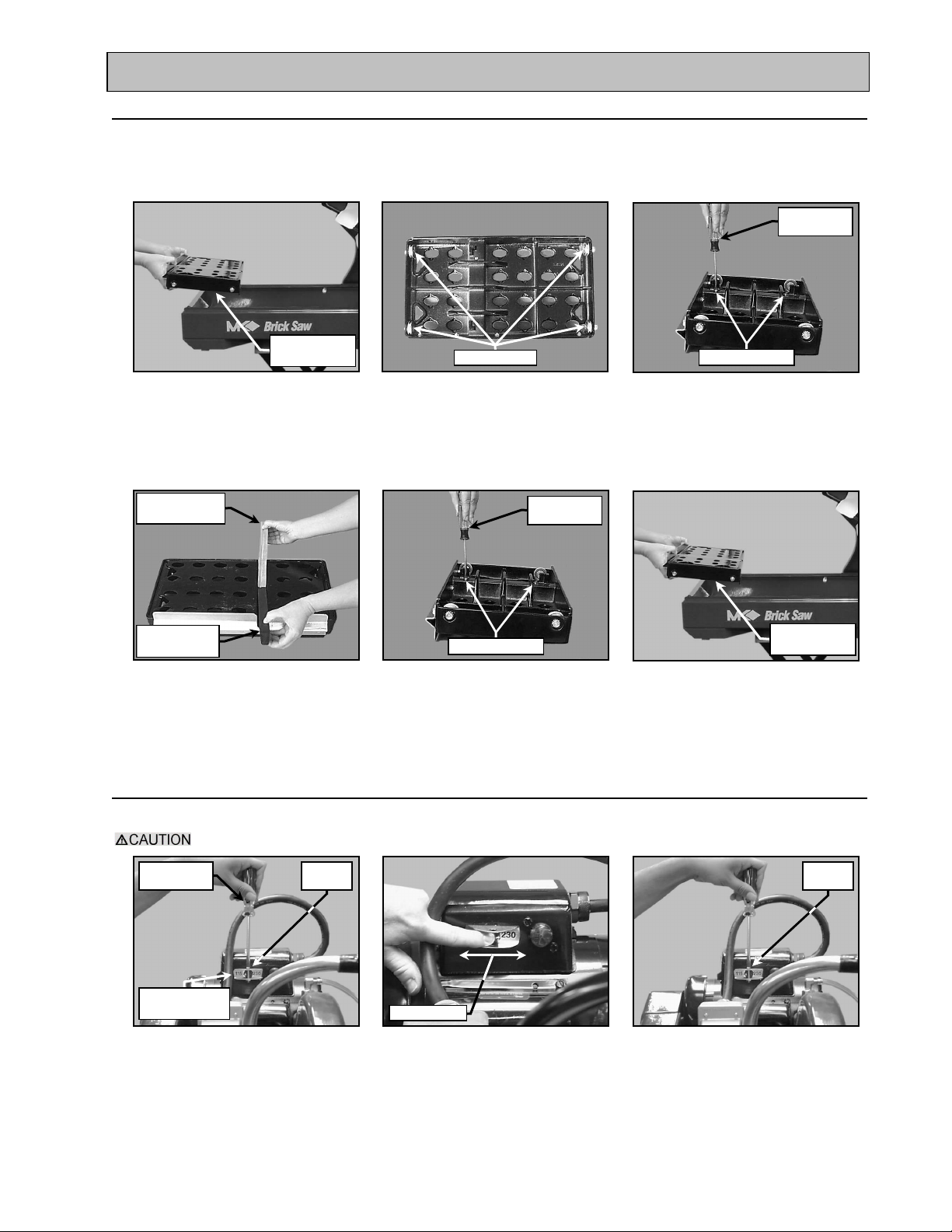
7. Protective Wooden Strip Replacement:
The protective wooden strip is to protect the Movable Cutting Table from damage during operation. Over
time, the wooden strip will become grooved from use. A grooved wooden strip will not support masonry
during cutting causing the blade to "break through" the piece instead of performing a smooth cut (MK
Diamond Part No. – 156427).
Phillips
Movable
Cutting Table Retaining Screw
(A)
Remove the Movable Cutting
Table
Worn Wooden
Strip
New Wooden
Strip
(D)
Replace the worn Protective
Wooden Strip with the new
Protective Wooden Strip
(B)
Place the Movable Cutting
Table on a Workbench with the
Roller Wheels facing up
Phillips
Retaining Screw
(E)
Place the Movable Cutting Table
on a Workbench with the Roller
Wheels facing up and reinstall
Remove the two Protective
Wooden Strip Retaining Screws
using a Phillips Screwdriver
Remove the Movable Cutting
(C)
Movable
Cutting Table
(F)
Table
8. Changing Voltage Setting:
Perform the following steps to change the voltage setting between 115v and 230v.
The power must be removed from the saw before changing the voltage setting.
Flat Blade
Voltage
Change Switch
(A)
Remove the Voltage Change
Switch Locking Screw using a
Flat Blade Screwdriver
MK-2000 Pro Revision 01/02, Effective Date January 10, 2002
Locking
(B)
Move the Voltage Change
Switch to the desired voltage
setting
Locking
(C)
Reinstall the Locking Screw
Page 30
Page 31
MAINTENANCE AND TROUBLESHOOTING
Blade
V-belt
clockwise to unlock
back
Screw
Wrench
Wrench
Bolt
clockwise to loosen
clockwise to loosen
Wrench
Switch
Position
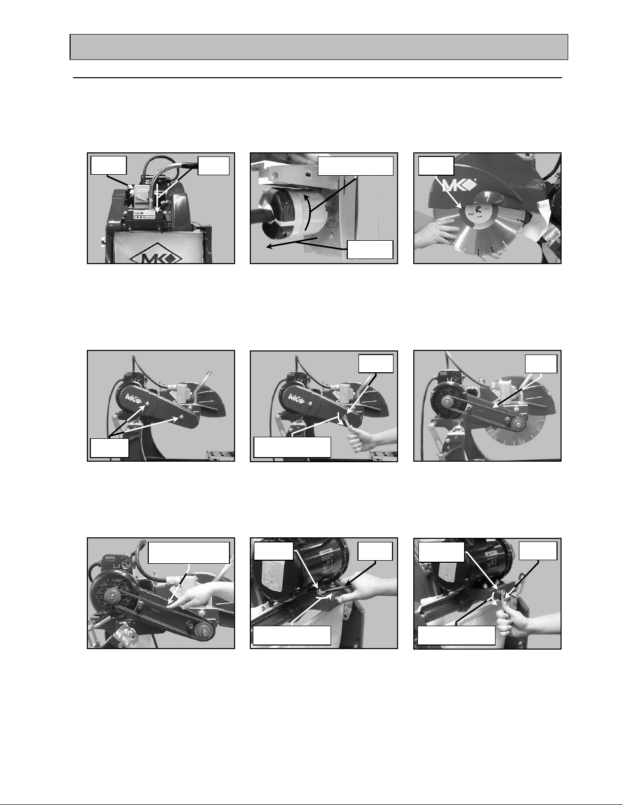
8. V-Belt Inspection, Adjustment and Replacement:
The MK-2000 PRO is designed with duel power transmission V-belts. In order to ensure the MK-2000 PRO
operates a peak efficiency, the two V-belts should be inspected monthly, and changed if they show signs of
damage and/or excessive wear.
NOTE: 1. When new belts are installed, they should be inspected and re-tensioned after the first forty-eight
(48) hours of operation.
ON/OFF
OFF
(A)
Ensure the ON/OFF Switch is
in the OFF position
Retaining
Turn counter-
Pull straight
(B)
Unplug the MK-2000 PRO
Polarized plug from the power
source by turning counterclockwise and then pulling
straight back
1/2-inch
Rotate counter-
clockwise to loosen
Remove
(C)
Remove the Blade (See the
Diamond Blade Change
Out Section)
Inspect
(D)
Locate the two Belt Guard
Retaining Screws
Remove the Belt Guard
Retaining Screws and the Belt
(E)
Guard using a 1/2-inch wrench
Check Tension 1/2-
way between pulleys
(G)
Check the V-belts for proper
tension, if the tension is
correct, go to step R (Proper
Retaining
Rotate counter-
(H)
Loosen the Motor Mounting
Bolts using a 1/2-inch wrench; if
re-tensioning only, go to step N
1/2-inch
tension 1/8-inch deflection)
MK-2000 Pro Revision 01/02, Effective Date January 10, 2002
(F)
Inspect the V-belts for cracks,
Fraying, separation and wear.
Go to step H if belt replacement
is required
Adjustment
Strap Bolt
Rotate counter-
9/16-inch
(I)
Loosen the Motor Adjustment
Strap using a 9/16-inch wrench
Page 31
Page 32
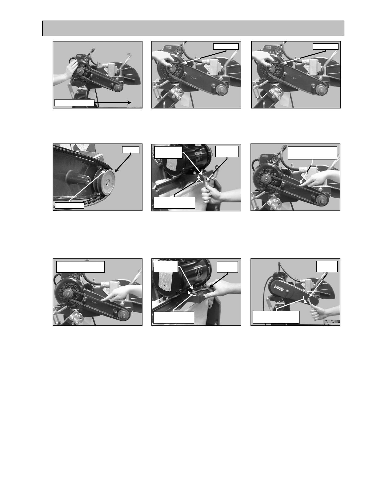
MAINTENANCE AND TROUBLESHOOTING
outer V-belts
Until Correct
Wrench
Wrench
Bolt
to tighten
to tighten
Wrench
Belt Seated
Old V-belt New V-belt
Direction of push
(J)
Push the Motor forward to
loosen the V-belts
Pulley
(M)
Verify the V-belts are seated in
the grooves of both pulleys
Continue Adjustment
(K)
Remove the old inner and
Adjustment
Strap Bolt
Rotate clockwise
9/16-inch
(N)
Tighten the Motor Adjustment
Strap using a 9/16-inch wrench to
remove slack
Retaining
1/2-inch
(L)
Install the new V-belts (MK Part
Number – 151723)
Check Tension 1/2-
way between pulleys
(O)
Check the V-belts for proper
tension, if the tension is
correct, go to step R (Proper
tension 1/8-inch deflection)
1/2-inch
proper V-belt tension is achieved
MK-2000 Pro Revision 01/02, Effective Date January 10, 2002
(P)
Repeat steps N and O until
Rotate clockwise
(Q)
Tighten the Motor Mounting
Bolts using a 1/2-inch Wrench
Rotate counter-
clockwise to loosen
(R)
Install the Belt Guard
Page 32
Page 33
MAINTENANCE AND TROUBLESHOOTING
go to Step D
Rotation Direction
Roller Wheels
TROUBLESHOOTING:
1. Blade Will Not Cut Properly:
If “Glazed,” Dress
(See Blade Dressing)
If not “Glazed,
go to Step B
(A)
Check the Blade for
smoothness or “Glazing” and
Dress the Blade if it is "Glazed"
Contact Place of Purchase or
MK Diamond (800 421-5830)
to verify Blade
If Blade correct,
go to Step E
(D)
Verify the Blade is correct for
the material being cut
If Rotation
correct, go
to Step C
(B)
Check for proper rotation
Return to
MK Diamond
for Repair
(E)
Return to MK Diamond
If Core bent,
change Blade
If Core not bent,
(C)
Ensure the blade core is not
bent
2. Movable Cutting Table Does Not Move Correctly:
Guide Rail
Return to
MK Diamond
for Repair
(A)
Check that the Movable Cutting
Table Guide Rails are clean
and clean if dirty
Ensure the Movable Cutting
Table Roller Wheels are clean
and in good condition, clean or
replace if necessary
MK-2000 Pro Revision 01/02, Effective Date January 10, 2002
(B)
(E)
Return to MK Diamond
Page 33
Page 34
MAINTENANCE AND TROUBLESHOOTING
Screwdriver
Blade
V-belt
connections
4. Vibration:
Diamond
If vibration exists,
go to step B
If no vibration exists,
replace Blade
(A)
Remove the Diamond Blade
and recheck vibration
Phillips
If vibration exists,
go to step E
(D)
Clean Motor and recheck
vibration
Remove
Belt Guard
(B)
Remove the Belt Guard
Return to
MK Diamond
for Repair
(E)
Return to MK Diamond
Go to
Step C
Go to
Step D
(C)
Remove the V-belts
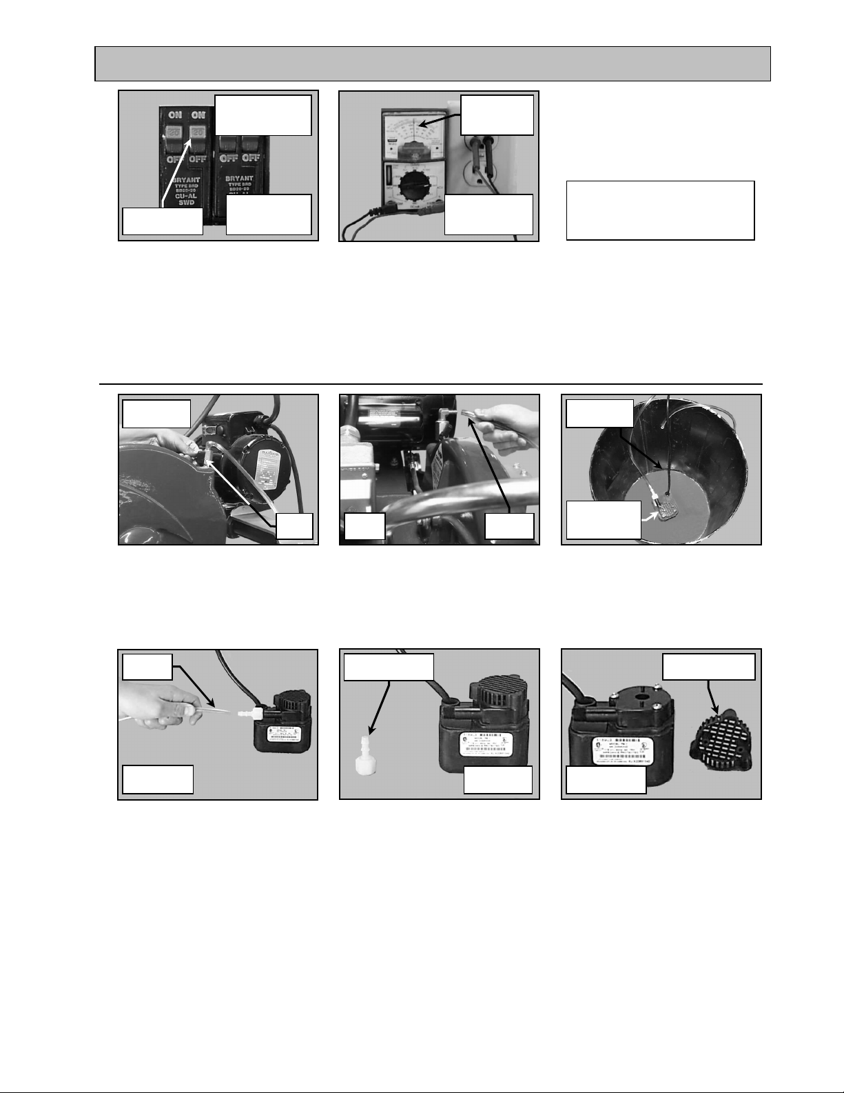
5. Blade Stops Turning:
Overload
Reset Switch
If motor does not
start, go to Step B
(A)
Allow motor to cool at least five
minutes and then depress
motor Overload Reset Switch
If all plugs connected,
(B)
Verify all power connections
are fully installed
Check all
go to Step C
If less than 20
Amps move saw
to 20 Amp circuit
Check Breaker
20 Amps or
greater
If circuit 20 Amp
or greater go to
Step E
(C)
Verify circuit breaker at least
20 amps – if not, move to 20-
amp circuit
MK-2000 Pro Revision 01/02, Effective Date January 10, 2002
Page 34
Page 35
MAINTENANCE AND TROUBLESHOOTING
Remove
water
to remove
Remove
Open
If tripped, reset
once if trips again,
go to step F
If circuit breaker
Check Breaker
tripped
not tripped go to
Step F
(E)
Verify Circuit Breaker is not
tripped; if tripped, reset the
Circuit Breaker once
(F)
Check power source voltage is
115V (240v if running at 240v)
– if not 115v move to another
Check for
correct circuit
voltage
If circuit breaker
not tripped go to
Step F
Return to
MK Diamond
for Repair
(G)
Return to MK Diamond
circuit
6. Cooling Flow:
If flow exists,
go to Step A
If flow exists,
go to Step D
Check
(A)
Check Cooling Flow Adjusting
Valve open
Pull to
If flow exist,
go to Step E
(D)
Remove the Cooling Transfer
Tube and check flow
Go to
Step C
Pull to
(B)
Remove the Cooling Transfer
Tube from the Blade Guard inlet
Remove
Discharge Fitting
If flow exists,
go to Step F
(E)
Remove the Pump Discharge
Fitting and check
Cover Pump
Suction with
(C)
Place Pump into a bucket of
water and check flow
Pull Intake Screen
If Screen clean,
go to Step G
(F)
Remove the Pump Intake
Screen and check for debris
MK-2000 Pro Revision 01/02, Effective Date January 10, 2002
Page 35
Page 36
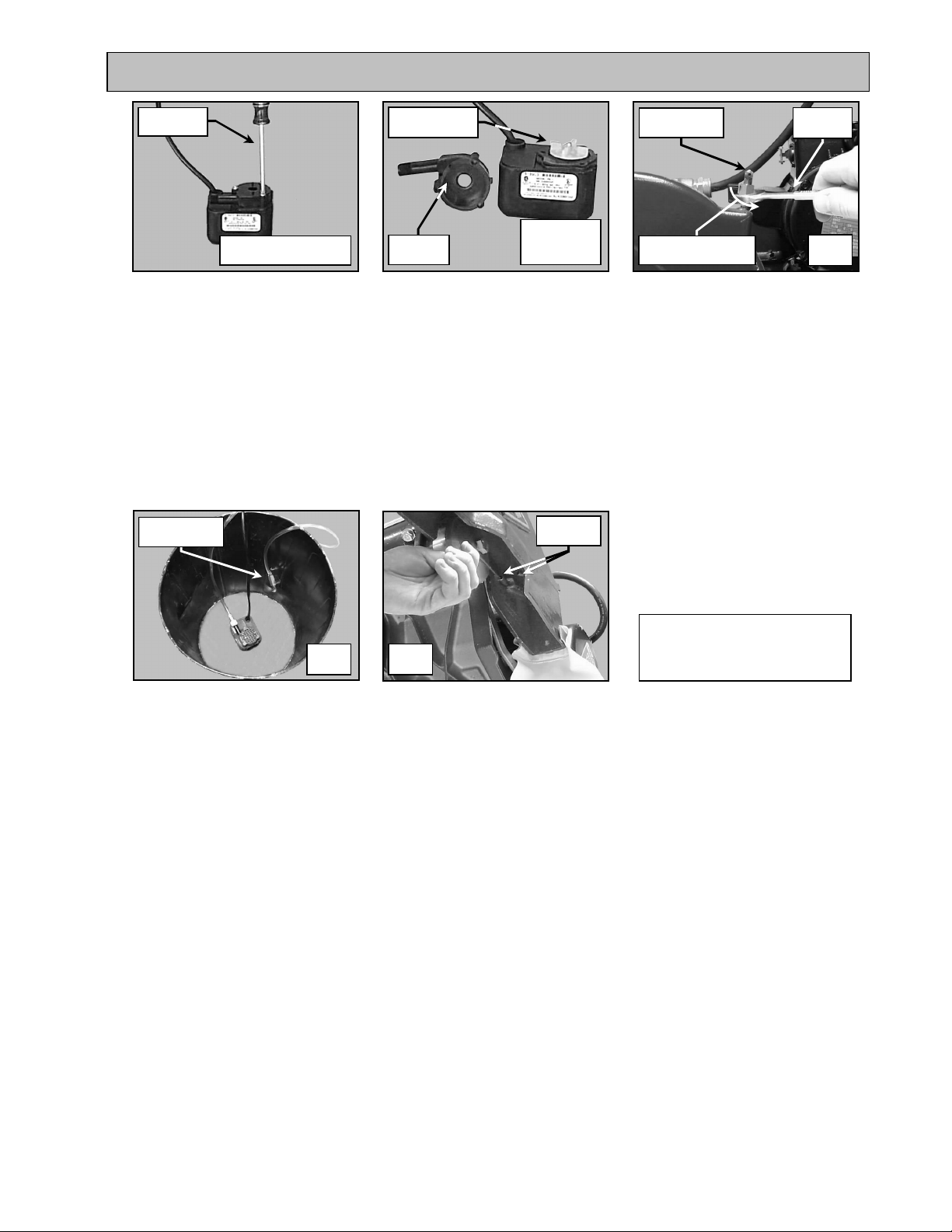
MAINTENANCE AND TROUBLESHOOTING
Screwdriver
go to Step H
clockwise to loosen
Phillips
Once Screws removed
(G)
Remove the 3 Pump Casing
Retaining Screws
Check Impeller
for damage
If no damage
Check for
restriction
or restrictions,
go to Step I
(H)
Remove the Pump Casing and
check for restriction; check
Impeller damage
Cooling Flow
Control Valve
Turn counter-
3/4- inch
Wrench
Go to
Step M
(I)
Using a 9/16-inch wrench,
remove the Flow Control Valve
from the Blade Guard
NOTE: “Rodding” cooling channels is performed by inserting a small wire rod through the cooling inlet on top
of the Blade Guard and directing the rod out through each of the cooling flow tubes located on the
underside o the Blade Guard. The cooling channels should be “rodded” until all ports are free of
foreign debris.
Cooling Flow
Control Valve
Rod
Channels
Go to
Step N
(J)
Attach the Flow Control Valve
to the Intake Fitting and check
flow (See Step C)
Go to
Step O
(K)
Rod Cooling Channels and
recheck flow; if after performing
Steps A to N flow still does not
exist, go to Step L
Return to
MK Diamond
for Repair
(L)
Return to MK Diamond
MK-2000 Pro Revision 01/02, Effective Date January 10, 2002
Page 36
Page 37
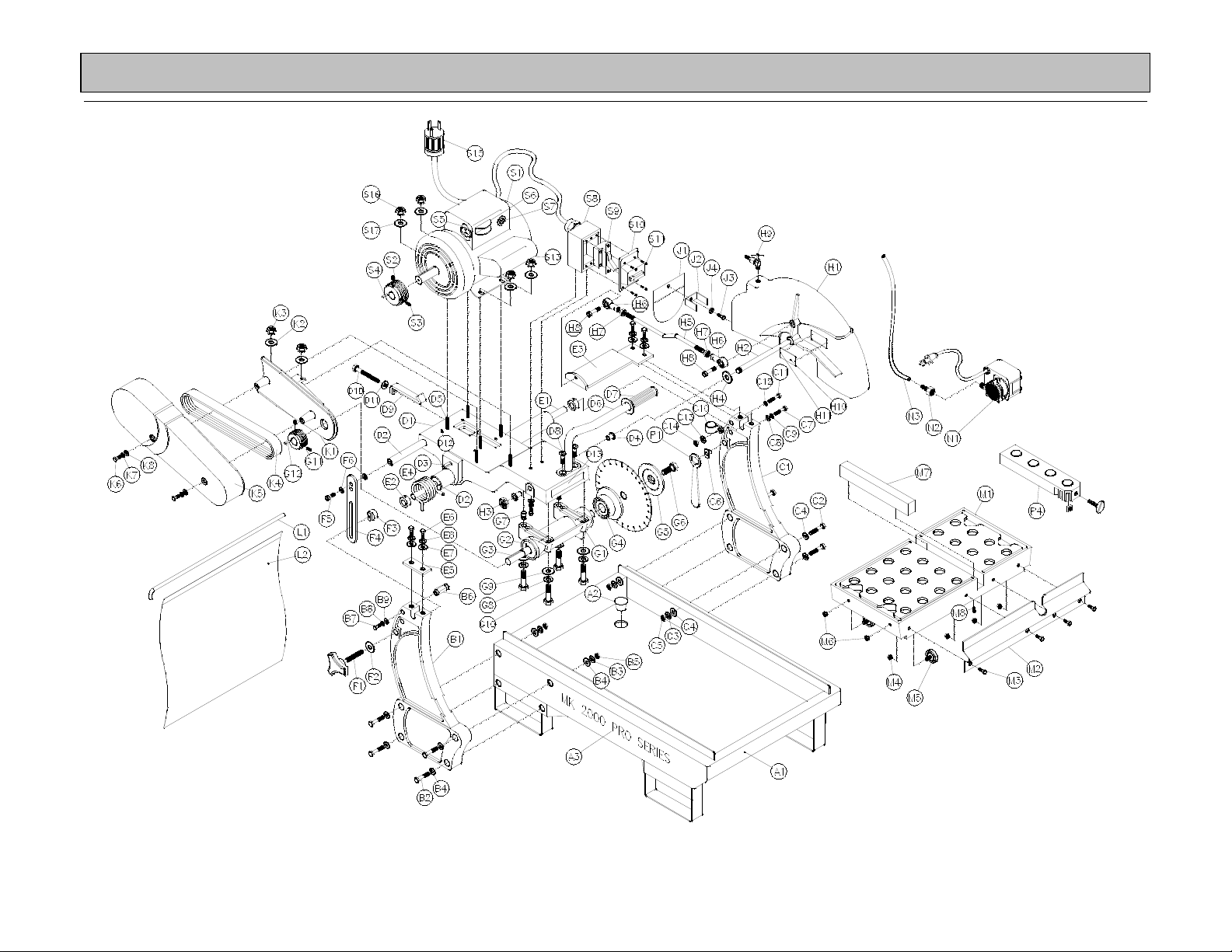
EXPLODED VIEW AND PARTS LIST
EXPLODED VIEW:
MK-2000 Pro Revision 01/02, Effective Date January 10, 2002 Page 37
Page 38

EXPLODED VIEW AND PARTS LIST
PARTS LIST:
Item Description Qty MK P/N
A Assembly, Frame, Brick Saw 1 n/a
A1 Frame, Weldment 1 158845
A2 Plug, Rubber Drain 1 153439
A3 Label, MK 2000 Brick Saw 2 155230
B Assembly, Upright, Left 1 n/a
B1 Post, Left 1 158846
B2 Screw, 5/16-18 x 1 3/4, Hex Head Cap 4 150919
B3 Washer, 5/16 Split Lock 4 151747
B4 Washer, 5/16 SAE Flat 8 151754
B5 Nut 5/16-18 Hex 4 101196
B6 Stud, Spring Retaining 1 231024
B7 Screw, 5/16-18 x 1 1/2, Hex Head Cap 1 152467
B8 Washer, 5/16 Split Lock 1 151747
B9 Washer, 5/16 SAE Flat 1 151754
C Assembly, Upright, Right n/a
C1 Post 1 158846
C2 Screw, 5/16-18 x 1 3/4, Hex Head Cap 4 150919
C3 Washer, 5/16 Split Lock 4 151747
C4 Washer, 5/16 SAE Flat 8 151754
C5 Nut 5/16-18 Hex 4 101196
C6 Hanger, Wrench 1 153945
C7 Screw, 3/8-16 x 1 3/4, Hex Head Cap 1 150920
C8 Washer, 3/8 SAE Flat 1 150923
C9 Washer, 3/8 SAE Split Lock 1 150925
C10 Clamp, Cushion Loop 1/2” (elec.) 1 152471
C11 Screw, 1/4-20 x 1 3/4 Hex Head Cap 1 231233
C12 Washer, 1/4 SAE Flat 2 151915
C13 Washer, 1/4 Split Lock 1 152591
C14 Nut 1/4-20 Hex 1 151893
D Assembly, Cutting Head n/a
D1 Casting, Cutting Head, Complete 1 150583
D2 Bar, Adjustment 1 150585
D3 Pin, Split Wrist 1 151358
D4 Bushing, Plastic 2 156441
D5 Stud, 5/16-18 x 1 1/2 6 153680
D6 Handle 1 139931
D7 Grip, Handle 7/8 I.D. 1 158608
D8 Screw, 3/8-16 x 3/4, Flat Socket Head Cap Screw 2 151752
D9 Strap, Motor Adjustment 1 150584
D10 Bolt, 3/8-16 x 3 1/2 Hex Head Cap 1 153147
D11 Washer, 3/8 SAE Flat 1 150923
D12 Stud, Pulley Alignment 1 231274
D13 Caution, Owners Manual 4 x 1 1/4 1 155576
MK-2000 Pro Revision 01/02, Effective Date January 10, 2002 Page 38
Page 39

EXPLODED VIEW AND PARTS LIST
Item Description Qty MK P/N
E Assembly, Pivot Shaft 1 assign
E1 Shaft, Pivot 1 154147
E2 Collar, Pivot Shaft 2 140012
E3 Bracket, Stay-Level 1 231234
E4 Spring, Torsion (4 coil) 1 231038
E5 Bracket, Pivot Shaft Retaining 1 231023
E6 Screw, 5/16-18 x 1 Button Head 4 151698
E7 Washer, 5/16 SAE Flat 4 151754
E8 Washer, 5/16 Split Lock 4 151747
F Assembly, Cutting Head Height Adjustment 1 n/a
F1 Knob, Tri (w/ 3/8-16 x 2 1/2 Stud) 1 231039
F2 Washer, 3/8 SAE Flat 1 150923
F3 T-Nut 1 231040
F4 Bracket, Height Adjustment 1 156839
F5 Screw, 1/2 x 1/2 Socket Hd. Shoulder, (3/8-16 x 1/2 Thread) 1 151753
F6 Washer, 1/2 SAE Flat 2 150923
G Assembly, Blade Shaft 1 n/a
G1 Blade Shaft-Arbor, Complete 1 153791
G2 Bearing, Blade Shaft 2 154594
G3 Shaft, Arbor 1 154639
G4 Flange, Inner 1 154640
G5 Flange, Outer 14 Inch M-Saw 1 132290
G6 Screw, 1/2-20 x 1 1/4, Hex Head Cap 1 152122
G7 Pin, Arbor Alignment 2 153946
G8 Washer, 5/16 Split Lock 4 151747
G9 Washer, 5/16 SAE Flat 4 151754
G10 Screw, 5/16-18 x 2 1/4 4 153951
G11 Pulley, 2 Groove, 2-1/2 x 5/8 1 133157
G12 Key, 1 1/8 x 3/16 1 150344
H Assembly, Blade Guard 1 n/a
H1 Blade Guard 1 158886
H2 Stud, Blade Guard Pivot 1 150581
H3 Nut, 1/2-20 Lock 1 153943
H4 Shim, 1/2 1 153952
H5 Rod, Adjustment Blade Guard 1 231052
H6 Ball Joint Rod End, Stamped, 3/8-24 2 156521
H7 Nut, Jam 3/8-24 2 231054
H8 Screw, 3/8 x 1/2 Shoulder, 5/16-18 x 1/2 Thread 2 231246
H9 Valve, Miniature Ball, 1/4 Male / Female 1 231248
H10 Tag, Serial 1 157007
H11 Tack, Metal 1/4 Hd. 2 155659
H12 Label, Warning, Blade Guard Failure 1 155588
J Assembly, Splash Guard n/a
J1 Curtain, Blade Guard 1 152417
J2 Bracket, Water Curtain 1 152723
J3 Screw, 1/4-20 x 1/2, Hex Head Cap 1 152608
J4 Washer, 1/4 SAE Flat 1 151915
MK-2000 Pro Revision 01/02, Effective Date January 10, 2002
Page 39
Page 40

EXPLODED VIEW AND PARTS LIST
Item Description Qty MK P/N
K Assembly, Belt Guard 1 n/a
K1 Belt Guard Inner 1 150590
K2 Washer, 3/8 SAE Flat 2 150923
K3 Nut, 5/16-18 Hex (w/ external tooth washer) 2 153942
K4 Belt, V AX-32 2 151723
K5 Belt Guard Outer 1 158867
K6 Screw, 5/16-18 x 1 3/4, Hex Head Cap 2 150919
K7 Washer, 5/16 Lock Split 2 151747
K8 Washer, 5/16 SAE Flat 2 151754
K9 Caution, Guard Removal 3 x 1 1/2 1 155587
L Assembly, Splash Curtain 1 n/a
L1 Rod, Splash Curtain 1 153956
L2 Curtain, Rear 1 152417
M Assembly, Table 1 133082
M1 Table 1 153790
M2 Stop-Rule, Table 1 134387
M3 Screw, 1/4-20 x 3/4 Hex Head Cap 4 152504
M4 Nut, 1/4-20, Hex w/ External Tooth Washer 4 153941
M5 Wheel Roller 4 133090
M6 Nut, 5/16-18, Hex w/ External Tooth Washer 4 153942
M7 Wood Strip, Table Insert 1 156427
M8 Screw, Pan HD Phil. #8 x1 2 151047
M9 Sticker, Inspected By: (not shown) 1 n/a
N Assembly, Pump Electric 1 n/a
N1 Pump, Water G-150A 1 151271
N2 Adapter, Plastic MNPT x 1/4 FNPT 1 151018
N3 Hose, Vinyl 1/4 ID 3 Ft. 132951
N4 Owner’s Manual, Water Pump G-150A 1 155745
N5 Carton, Water Pump G-150A 1 154016
N6 Insert, Foam Water Pump G-150A 1 154017
P Assembly, Accessory Pack 1 n/a
P1 Wrench, Masonry Saw 1 134056
P2 Carton, Accessory (not shown) 1 153575
P3 Insert, Accessory (not shown) 1 153576
P4 Assembly, Rip Guide, Large
Rip Guide, Large (Comp)
Screw, 5/16-18 x 1 1/2 Thumb
Nut, 5/16-18 Square
P5 Warranty Card 1 155037
P6 Sell Sheet, Tile Accessory 1 156915
P7 Owners Manual, MK-2000 Pro Series 1 158753
1
1
1
1
n/a
132332
150303
151156
MK-2000 Pro Revision 01/02, Effective Date January 10, 2002
Page 40
Page 41

EXPLODED VIEW AND PARTS LIST
Item Description Qty MK P/N
SB Assembly, Mtr 110/220v 1 Ph 60 Hz 2 Hp n/a
SB1 Motor, 115/230v 60 Hz 2 Hp 1 231095
SB2
SB3
SB4 Key, 1-1/8 x 3/16 1 150344
SB5 Receptacle, 20 Amp 115 volt 1 154621
SB6 Switch, Voltage Change 1 150577
SB7 Switch, Thermal Overload TPMlSJ24AB 1 153503
SB8 Box, Switch 1 139758
SB9 Switch, On/Off 30 Amps/250 volts 1 139741
SB10 Cover, Switch Box 1 139766
SB11 Screw, 10-32 x 1/4 Slotted Round Head Machine 4 231090
SB12 Screw, 1/4-20 x 3/4 Hex Head 2 152676
SB13 Capacitor, HSG 1 150574
SB14 Capacitor, Oil MK2000 OC3020F12 1 152412
SB15 Plug, Twist Lock 20 Amp125 volt (NEMAL520P) 1 154556
SB16 Nut, 5/16-18 w/ External Tooth Washer 4 153942
SB17 Washer, 5/16 SAE, Flat 4 151754
SB18 Warning, Cord Selection 2 3/4 x 2 1/2 1 155672
SB19 Caution, Ground Fault Interrupter 2 1/8 x 1 1 155678
SB20 Attachment for Water Pump 1 1/2 x 3/4 1 154408
SB21 Motor, Cool Push 1 x 5/8 1 154409
Pulley, 2 Groove, 2 -1 /2 x 3/4
Screw, 5/16-18 x 1/4, Set
1
2
231083
231239
SC Assembly, Mtr 110/220v 1 Ph 50 Hz 2 Hp n/a
SC1 Motor, 115/230v 50 Hz 2 Hp 1 231096
SC2
SC3
SC4 Key, 1 - 1/8 x 3/16 1 150344
SC5 Receptacle, 20 Amp 115 volt 1 154621
SC6 Switch, Voltage Change 1 150577
SC7 Switch, Thermal Overload TPMlSJ24AB 1 153503
SC8 Box, Switch 1 139758
SC9 Switch, On/Off 30 Amps/250 volts 1 139741
SC10 Cover, Switch Box 1 139766
SC11 Screw, 10-32 x 1/4, Slotted Round Head Machine 4 231090
SC12 Screw, 1/4 - 20 x 3/4 Hex Head 2 152676
SC13 Capacitor, HSG 1 150574
SC14 Capacitor, Oil MK2000 OC3020F12 1 152412
SC15 Plug, Twist Lock 20 Amp125 volt (NEMAL520P) 1 154556
SC16 Nut, 5/16-18 w/ External Tooth Washer 4 153942
SC17 Washer, 5/16 SAE, Flat 4 151754
SC18 Warning, Cord Selection 2 3/4 x 2 1/2 1 155672
SC19 Caution, Ground Fault Interrupter 2 1/8 x 1 1 155678
SC20 Attachment for Water Pump 1 1/2 x 3/4 1 154408
SC21 Motor, Cool Push 1 x 5/8 1 154409
Pulley, 2 Groove, 2 –1 /2 x 3/4
Screw, 5/16-18 x 1/4, Set
1
2
231083
231239
MK-2000 Pro Revision 01/02, Effective Date January 10, 2002
Page 41
Page 42
EXPLODED VIEW AND PARTS LIST
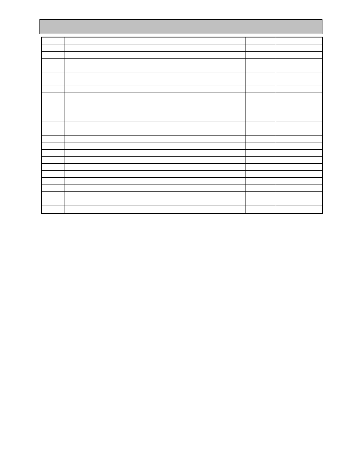
Item Description Qty MK P/N
SD Assembly, Mtr 110/220v 1 Ph 60 Hz 3 hp n/a
SD1 Motor, 115/230v 60 Hz 3 hp (saw duty) 1 158752
SD2
SD3
SD2
SD3
SD4 Key, 1 - 1/8 x 3/16 1 150344
SD5 Receptacle, 20 Amp 115 volt 1 154621
SD6 Switch, Voltage Change 1 150577
SD7 Switch, Thermal Overload TPMlSJ24AB 1 153503
SD8 Box, Switch 1 139758
SD9 Switch, On/Off 30 Amps/250 volts 1 139741
SD10 Cover, Switch Box 1 139766
SD11 Screw, 10-32 x 1/4, Slotted Round Head Machine 4 231090
SD12 Screw, 1/4 - 20 x 3/4 Hex Head 2 152676
SD13 Capacitor, HSG 1 150574
SD14 Capacitor, Oil MK2000 OC3020F12 1 152412
SD15 Plug, Twist Lock 20 Amp125 volt (NEMAL520P) 1 154556
SD16 Nut, 5/16-18 w/ External Tooth Washer 4 153942
SD17 Washer, 5/16 SAE, Flat 4 151754
SD18 Warning, Cord Selection 2 3/4 x 2 1/2 1 155672
SD19 Caution, Ground Fault Interrupter 2 1/8 x 1 1 155678
SD20 Attachment for Water Pump 1 1/2 x 3/4 1 154408
SD21 Motor, Cool Push 1 x 5/8 1 154409
Pulley, 2 Groove, 2 –1 /2 x 3/4
Screw, 5/16-18 x 1/4, Set
Pulley, 2 Groove, 2 –1 /2 x 3/4
Screw, 5/16-18 x 1/4, Set
1
2
1
2
231083
231239
231083
231239
MK-2000 Pro Revision 01/02, Effective Date January 10, 2002
Page 42
Page 43
THEORY
THEORY OF DIAMOND BLADES:
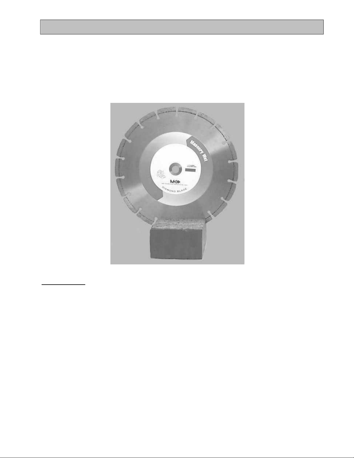
Diamond blades do not really cut; they grind the material through friction. Diamond crystals, often visible at
the leading edge and sides of the rim/segment, remove material by scratching out particles of hard, dense
materials, or by knocking out larger particles of loosely bonded abrasive material. This process eventually
cracks or fractures the diamond particle, breaking it down into smaller pieces. As a result, a diamond blade
for cutting soft, abrasive material must have a hard metal matrix composition to resist this erosion long
enough for the exposed diamonds to be properly utilized. Conversely, a blade for cutting a hard, nonabrasive material must have a soft bond to ensure that it will erode and expose the diamonds embedded in
the matrix. These simple principles are the foundation of “controlled bond erosion”.
Types of Cutting:
There are two basic types of cutting-Dry or Wet. The choice of which type of blade to use depends on:
• The requirements of the job
• The machine/tool utilizing the diamond blade
• The preference of the operator
In the case of DRY cutting, the overwhelming popularity and quantity of hand-held saws and the flexible
nature of MK Diamond blades to professionally handle most ceramic, masonry, stone and concrete materials,
make the DRY cutting blade a very attractive tool. When using a DRY blade, the user must be aware of
distinct operating practices to ensure optimum performance. DRY cutting blades require sufficient airflow
about the blade to prevent overheating of the steel core. This is best accomplished by shallow, intermittent
cuts of the material with periods of “free-spinning” (for several seconds) between each cut, to maximize the
cooling process.
For WET cutting applications, MK has the exact blade to compliment both the material to be cut and the wet
cutting machine to be used. During cutting operations, liberal amounts of water act as a coolant to support
the cutting effectiveness and longevity of the WET blade. Additionally, using water adds to the overall safety
of cutting operations by keeping the dust signature down.
Know All You Can About the Material You Wish to Cut
MK-2000 Pro Revision 01/02, Effective Date January 10, 2002 Page 43
Page 44
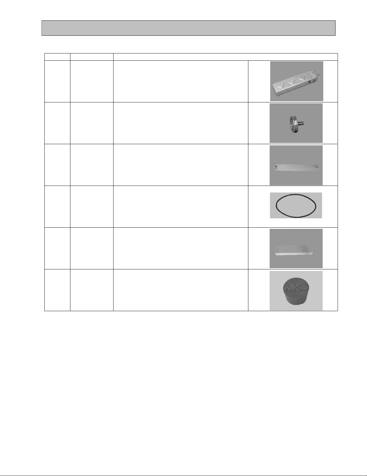
ACCESSORIES
ACCESSORIES:
ITEM NUMBER DESCRIPTION
1. 132332 Adjustable Cutting Guide
2. 133090 Roller Wheel
3. 156427 Protective Wooden Strip
4. 151723 V Belt
5. 152792 Dressing Stick
6.
153439 Rubber Drain Plug
MK-2000 Pro Revision 01/02, Effective Date January 10, 2002 Page 44
Page 45

ORDERING and RETURN INFORMATION
ORDERING INFORMATION:
You may order MK Diamond products through your local MK Diamond distributor or, you may order direct
from MK Diamond.
NOTE: There is a $25.00 minimum order when ordering direct from MK Diamond. All purchases must be
made using VISA or MasterCard.
When ordering direct from MK Diamond, please have the following information ready before calling:
• The Model Number of the saw
• The Serial Number of the saw
• Where the saw was purchased and when
• The Part Number for the part(s) being ordered
• The Part Description for the part(s) being ordered
All parts may be ordered by calling toll free to – 800 421-5830 or 310 539-5221 and asking for Customer
Service. For technical questions, call – 800 474-5594.
RETURN MATERIALS POLICY:
To expedite the service relative to the return of a product purchased through MK Diamond, please observe
the following:
NOTE: When returning all items, they must have been purchased within the previous twelve (12) months.
• Have the Model Number of the saw
• Have the Serial Number of the saw
• Have the location of where the saw was purchased
• Have the date when the saw was purchased
• Contact Customer Service for approval to return the item(s)
• Obtain a Returned Goods Number (RGA) authorizing the return
• Follow the packaging instructions in the following section
• Ensure your item(s) are prepaid to the destination
For returned items, call toll free to – 800 421-5830 or 310 539-5221 and ask for Customer Service. For
technical questions, call – 800 474-5594 or 310 257-2845.
PACKAGING INSTRUCTIONS:
• Remove the Blade guard and Support Angle Assembly
• Dry the saw before shipping
• When packing, include the following: MK-2000 PRO, Diamond Blade, Blade guard and Support Angle
Assembly and Adjustable Cutting Guide (Other Accessories are not required)
• Package the unit in its original container or one of comparable size (do not ship the unit partially exposed)
• Ensure all parts are secured in the packaging to prevent moving
AUTHORIZED SERVICE CENTERS:
For quicker repair time, you may contact MK Diamond Customer Service, toll free, at – 800 421-5830 or 310
539-5221 for the Authorized Service Center closest too you. For technical questions, call – 800 474-5594.
MK-2000 Pro Revision 01/02, Effective Date January 10, 2002
Page 45
Page 46

MK-2000 Pro SERIES
BRICK SAW
OWNER’S MANUAL &
OPERATING INSTRUCTIONS
CALIFORNIA PROPOSITION 65 MESSAGE:
Some dust created by power sanding, sawing, grinding, drilling, and other
construction activities contain chemicals known [to the State of California] to cause
cancer, birth defects or other reproductive harm. Some examples of these
chemicals are:
• Lead, from lead-based paints
• Crystalline silica, from bricks and cement and other masonry products and
• Arsenic and chromium, from chemically treated lumber
Your risk from these exposures varies depending on how often you do this type of
work. To reduce your exposure to these chemicals, work in a well-ventilated area,
and work with approved safety equipment, such as those dust masks that are
specially designed to filter out microscopic particles.
MK DIAMOND PRODUCTS, INC
1315 STORM PARKWAY, TORRANCE, CA 90509-2803
310 539 5158
 Loading...