

Page 1
www.mkdiamond.com
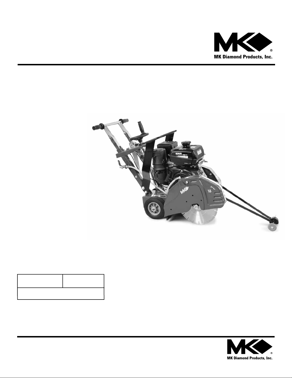
Gas Powered
Concrete Saw
MK-1600
OWNER’S MANUAL &
OPERATING INSTRUCTIONS
Revision 202
Manual Part# 157841
Caution: Read all safety and operating instructions
before using this equipment. This owner’s manual
MUST accompany the equipment at all times.
03.2013
Page 2
INTRODUCTION
Congratulations on your purchase of a MK-1600 Concrete Saw. We are certain that you will
be pleased with your purchase. MK Diamond takes pride in producing the nest construction
power tools and diamond blades in the industry.
Operated correctly, your MK-1600 Concrete Saw should provide you with years of service. In
order to help you, we have included this manual. This owners manual contains information necessary to operate and maintain your MK-1600 Concrete Saw safely and correctly. Please take
the time to familiarize yourself with the MK-1600 Concrete Saw by reading and reviewing this
manual.
Read and follow all safety, operating and maintenance instructions.
If you should have questions concerning your MK-1600 Concrete Saw, please feel free to call
our friendly customer service department at: 800 421-5830
Regards,
MK Diamond
NOTE THIS INFORMATION FOR FUTURE USE:
MODEL NUMBER:
SERIAL NUMBER:
PURCHASE PLACE:
PURCHASE DATE:
NOTE: For your (1) one year warranty to be effective, complete the warranty card
(including the Serial Number) and mail it in as soon as possible.
2
Page 3

TABLE OF CONTENTS
SAFETY
Safety Messages 4
Damage Prevention Message 4
General Safety Precautions and Hazard Symbols 5
California Proposition 65 Message 8
Prestart Safety 9
Safety Label Locations 10
Product Specications 11
UNPACKING, TRANSPORT and ASSEMBLY
Unpacking 12
Contents 12
Transport 13
Assembly 14-15
STARTUP, OPERATION and SHUTDOWN
Startup 16-17
Operation 18-20
Shutdown 21
Cleanup 21
MAINTENANCE AND TROUBLESHOOTING
Maintenance 22-30
Troubleshooting 31
EXPLODED VIEW & PARTS LIST
Exploded View 34-36
Parts List 37-39
THEORY
Theory Of Diamond Blades 40
ACCESSORIES ORDERING and RETURN INSTRUCTIONS
Accessories 41
Ordering Information 42
Return Material Policy 42
Packaging Instructions 42
Authorized Service Centers 42
Warranty 43
3
Page 4
MK-1600 SAFETY
Safety precautions should be followed at all times when operating this equipment. Failure to read and
understand the Safety Precaution and Operating Instructions could result in injury to yourself and
others.
This Operation Manual has been developed to provide complete instructions for the safe and efcient
operation of the MK-1600 Concrete Saw.
Before using this saw, ensure that the person operating the equipment has read and understands all
instructions in this manual.
Descriptions, illustrations, and photos are as accurate as possible at the time of publication. Photos
may include optional equipment or accessories and may not show all models covered by this manual.
SAFETY MESSAGE / ALERT SYMBOLS
A safety message alerts you to potential hazards that could hurt you or others. Each safety message is
preceded by a safety alert symbol ( ) and one of three words: DANGER, WARNING, or CAUTION.
DANGER
You WILL be KILLED or SERIOUSLY INJURED if you do not follow directions.
WARNING
You CAN be KILLED or SERIOUSLY INJURED if you do not follow directions.
CAUTION
You CAN be INJURED if you do not follow directions. It may also be used
to alert against unsafe practices.
Each message tells you what the hazard is, what can happen, and what you can do to avoid or
reduce injury. Other important messages are preceded by the word NOTICE.
NOTICE
You can cause PROPERTY DAMAGE to your machine if you don’t follow directions.
The safety labels should be periodically inspected and cleaned by the user to maintain good legibility
at a safe viewing distance. If the label is worn, damaged or illegible, it should be replaced. Contact
MK Diamond or your dealer for replacement.
DAMAGE PREVENTION AND INFORMATION MESSAGES
A Damage Prevention Message is to inform the user of important information and/or instructions that
could lead to equipment or other property damage if not followed. Information messages convey
information that pertains to the equipment being used. Each message will be preceded by the word
note, as in the example below.
NOTE: Equipment and/or property damage may result if these instructions are not followed.
4
Page 5
(
(
)
)
MK-1600 SAFETY
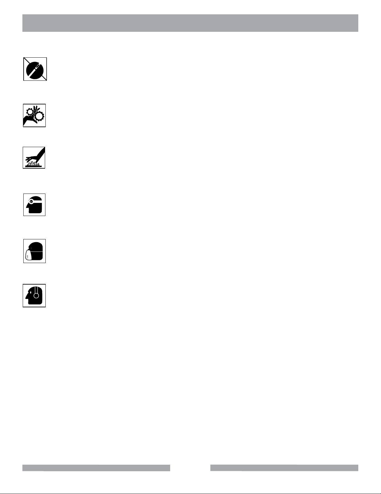
GENERAL SAFETY PRECAUTIONS AND HAZARD SYMBOLS
SAFETY PRECAUTIONS
In order to prevent injury, the following safety precautions and symbols should be followed
at all times!
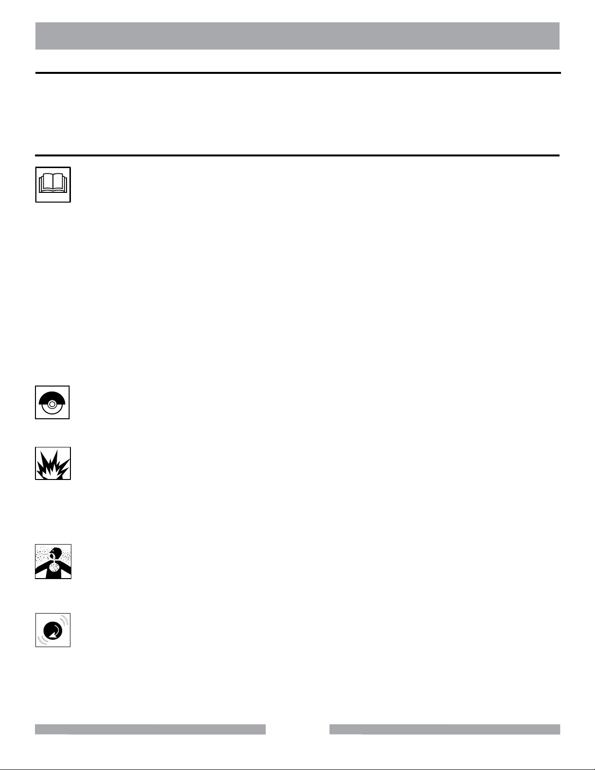
GENERAL SAFETY
DO NOT operate or service this equipment before reading this entire manual.
This equipment should not be operated by persons under 18 years of age.
NEVER operate this equipment when not feeling well due to fatigue, illness or taking
medicine.
NEVER operate this equipment under the inuence of drugs or alcohol.
Whenever necessary, replace nameplate, operation and safety decals when they become
difcult to read.
ALWAYS store equipment properly when it is not being used. Equipment should be stored
in a clean, dry location out of the reach of children.
KEEP GUARDS IN PLACE
In order to prevent injury, keep guards in place and in working order at all times.
EXPLOSIVE FUEL!
Gasoline is extremely ammable, its vapors can explode if ignited; store only in approved
containers, in well-ventilated, unoccupied buildings and away from sparks or ames. Do not
ll the fuel tank while the engine is running or hot. Spilled fuel could ignite if it contacts hot
parts or sparks from ignition. Do not start the engine near spilled fuel. Never use gasoline
as a cleaning agent. Never operate the machine in an explosive atmosphere.
LETHAL EXHAUST GASES
Engine exhaust gasses contain poisonous carbon monoxide, an odorless colorless gas
that can cause death if inhaled. Avoid inhaling exhaust fumes, and never run the engine
in a closed building or conned area.
ENGINE OVER-SPEED
Never tamper with the governor components or settings to increase the maximum speed of
the machine. Severe personal injury and/or equipment damage could result if the equip-
ment is operated speeds above design maximum.
5
Page 6
MK-1600 SAFETY
on
ACCIDENTAL STARTS
Before starting the engine, be sure the ON/OFF switch is in the “OFF” position to prevent
accidental starting. Place the ON/OFF switch in the OFF position before performing any
service operation.
ROTATING OR MOVING PARTS
Keep hands, feet, hair, and clothing away from all moving parts to prevent injury. Never
operate a power tool with shrouds or guards removed.
HOT PARTS
Engine components can become extremely hot from operation. To prevent severe burns, do
not touch these areas while the engine is running, or immediately after it is turned off. Never
operate the engine with heat shields removed.
ALWAYS USE SAFETY GLASSES
Safety glasses should always be worn when working around power tools. Everyday eyeglasses only have impact resistant lenses and may not prevent eye injury; they are NOT
safety glasses.
ALWAYS USE RESPIRATORY PROTECTION
Exhaust gases may be harmful if inhaled. Do not operate gas-powered equipment in
enclosed spaces. Respiratory protection should be worn when operating gas powered
equipment.
ALWAYS USE HEARING PROTECTION
To reduce the possibility of hearing loss, always use hearing protection when operating
equipment.
REMOVE ADJUSTING KEYS AND WRENCHES
Form a habit of checking to see that keys and adjusting wrenches are removed from the power tool
before it is turned on.
KEEP WORK AREA CLEAN
Cluttered work areas and benches invite accidents.
DO NOT USE IN DANGEROUS ENVIRONMENTS
Do not operate equipment in dangerous environments. Always keep the work area well lighted.
KEEP CHILDREN AWAY
All visitors and children should be kept a safe distance from work area.
MAKE WORKSHOP KID PROOF
Make the workshops kid proof by using padlocks, master switches or by removing starter keys.
6
Page 7

MK-1600 SAFETY
DO NOT FORCE THE TOOL
A power tool will do a job better and safer operating at the rate for which it was designed.
USE THE RIGHT TOOL
Do not force a tool or an attachment, to do a job that it was not designed to do.
WEAR PROPER APPAREL
Do not wear loose clothing, gloves, neckties, rings, bracelets, or other jewelry that may be caught in
moving parts. Nonslip footwear is recommended. Wear protective hair covering to contain long hair.
SECURE WORK
Clamps or a vise should be used to hold work whenever practical. Keeping your hands free to oper-
ate a power tool is safer.
DO NOT OVERREACH
Keep proper footing and balance at all times by not overreaching.
MAINTAIN TOOLS WITH CARE
Keep tools sharp and clean for the best and safest performance. Always follow maintenance instruc-
tions for lubricating and when changing accessories.
SHUTDOWN TOOL
The saw should always be shutdown before servicing or when changing accessories such as blades,
bits, cutters, etc...
USE RECOMMENDED ACCESSORIES
Consult the owner’s manual for recommended accessories. Using improper accessories may increase the risk of personal or by-stander injury.
NEVER STAND ON THE TOOL
Serious injury could occur if a power tool is tipped, or if a cutting tool is unintentionally contacted.
NEVER LEAVE TOOL RUNNING UNATTENDED – TURN POWER OFF
Do not leave a tool until it comes to a complete stop. Always turn a power tool OFF when leaving the
work area, or, when a cut is nished.
CHECK FOR DAMAGED PARTS
Before using a power tool, check for damaged parts. A guard or any other part that is damaged
should be carefully checked to determine it would operate properly and perform its intended function. Always check moving parts for proper alignment or binding. Check for broken parts, mountings
and all other conditions that may affect the operation of the power tool. A guard or any damaged part
should be properly repaired or replaced.
DIRECTION OF FEED
Always feed work into a blade or cutter against the direction of rotation. A blade or cutter should al-
ways be installed such that rotation is in the direction of the arrow imprinted on the side of the blade
or cutter.
7
Page 8

MK-1600 SAFETY
SILICA DUST WARNING
Grinding/cutting/drilling of masonry, concrete, metal and other materials with silica in their composition may give off dust or mists containing crystalline silica. Silica is a basic component of sand,
quartz, brick clay, granite and numerous other minerals and rocks. Repeated and/or substantial inha-
lation of airborne crystalline silica can cause serious or fatal respiratory diseases, including silicosis.
In addition, California and some other authorities have listed respirable crystalline silica as a sub-
stance known to cause cancer. When cutting such materials, always follow respiratory precautions.
CALIFORNIA PROPOSITION 65 MESSAGE
Some dust created by power sanding, sawing, grinding, drilling, and other construction activities contain chemicals known (to the State of California) to cause cancer, birth defects or other reproductive
harm. Some examples of these chemicals are:
• Lead, from lead-based paints
• Crystalline silica, from bricks and cement and other masonry products
• Arsenic and chromium, from chemically treated lumber
For further information, consult the following sources:
http://www.osha.gov/dsg/topics/silicacrystalline/index.html
http://www.cdc.gov/niosh/consilic.html
http://oehha.ca.gov/prop65/law/P65law72003.html
http://www.dir.ca.gov/Title8/sub4.html
Your risk from these exposures varies depending on how often you do this type of work. To reduce
your exposure to these chemicals, work in a well-ventilated area, and work with approved safety
equipment, such as those dust masks that are specially designed to lter out microscopic particles.
8
Page 9

MK-1600 PRE-START
Before starting the machine, ALWAYS check that all guards are in position and correctly tted. Check
the machine for loose bolts before starting.
Keep area around the machine clear of obstructions which could cause persons to fall onto moving parts.
ALWAYS ensure that the machine is on level ground before using. Know how to stop the machine
quickly in case of emergency. NEVER try to stop a moving blade with your hands.
• NEVER disconnect any “emergency or safety devices”. These devices are intended for
operator safety. Disconnection of these devices can cause severe injury, bodily harm or
even death! Disconnection of any of these devices will void all warranties.
• Unauthorized equipment modications will void all warranties. Manufacturer does not
assume responsibility for any accident due to equipment modications.
• NEVER use accessories or attachments, which are not recommended by MK Diamond for
this equipment. Damage to the equipment and/or injury to user may result.
WARNING
DO NOT use woodcutting, or carbide blades on this machine! Use ONLY Diamond blades on machine.
9
Page 10
MK-1600 SAFETY
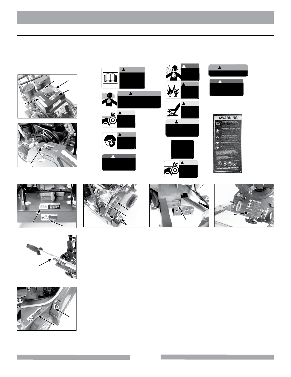
OPERATION & SAFETY DECALS
The MK-1600 Concrete Saw is equipped with a number of safety decals. These decals are provided
for operator safety and maintenance information. Should any of these operation or safety decals be-
come unreadable, replacements can be obtained by calling (800) 262-1575.
DANGER
WARNING
!
H
F
(A)
G
(B)
E
(C)
(D)
The exhaust from this product
(E)
contains chemicals known to
C
the State of California to cause
cancer, birth defects or other
reproductive harm.
DO NOT operate
this equipment
before reading
the owners’
manual!
!
CAUTION
!
WARNING
!
In the event of
blade failure,
replace blade
guard
immediately.
WARNING
Grinding/cutting/drilling of masonry, concrete, metal and other materials with silica in
their composition may give off dust or mists containing crystalline silica. Silica is a basic
component of sand, quartz, brick clay, granite and numerous other minerals and rocks.
Repeated and/or substantial inhalation of airborne crystalline silica can cause serious
or fatal respiratory diseases, including silicosis. In addition, California and some other
authorities have listed respirable crystalline silica as a substance known to cause cancer.
DO NOT
operate without
guards in place.
(3 of them)
DANGER
!
Accidental start hazard.
Disconnect spark plug
prior to servicing.
Lethal exhaust
gases. Use only
in well ventilated
areas. DO NOT
use indoors.
WARNING
!
When refueling
stop engine and
allow to cool.
DO NOT overfill
tank.
CAUTION
!
DO NOT
touch hot
surface.
CAUTION
!
FOR INFORMATION ON
SERVICE OR
WARRANTY
PLEASE CALL
1-800-474-5594
CAUTION
!
Keep
hands and
feet clear.
(F)
(G)
(H)
(I)
(J)
(K)
!
WARNING
Handle bar NOT a lifting point.
NOTICE
!
Overtensioning of belts
will result in premature
crank and/or bearing failure.
(L)
(M)
Concrete Saw Warning Label
Sheet Part# 166009
(N)
A K
L
B
I
M
C
J
N
Location Description
A
Frame Read Manual
B
Frame Proposition 65, Dust Warning
C
Shaft Cover & Belt Guard Guards in Place
D
Blade Guard Replace Blade Guard
E
Gas Tank/Top Exhaust/Cancer
F
Gas Tank/Top Lethal Exhaust
G
Gas Tank/Top Refueling
H
Gas Tank Hot Surface
I
Blade Guard Accidental Start
J
Frame/Back Service
D
K
Frame/Front Hand & Feet Clear
L
Handle Lifting Point
M
Belt Guard Overtensioning Belts
N
Console Machinery Hazard
10
Page 11
MK-1600
PRODUCT SPECIFICATION
PRODUCT SPECIFICATIONS
The MK-1600 is a versatile gas powered Concrete Saw. Operated and used according to this manual, the MK-1600 will provide years of dependable service.
General Description
The MK-1600 is engineered as a portable concrete saw powered by a Honda, Vanguard or Kohler
gas engine.The saw is capable of 6-5/8” depth of cut with an 18” blade.
MotorandWeightSpecications
Motor and Weight specications for the MK-1600 are listed below.
GeneralSpecications
Arbor Size 1” (25mm)
Blade Capacity 18” (45mm)
Blade RPM 2,700
Depth of Cut 6-5/8” (168mm)
L x W x H (inches) 42” x 25” x 39”
L x W x H (mm) 1067 x 635 x 991
Model
Engine Honda (Gas) Honda (Gas) Subaru (Gas) Vanguard (Gas)
Power GX240 Cyclone GX390 Cyclone EH41 V-Twin
Weight 210 lbs. (95 kgs) 223 lbs. (101 kgs) 223 lbs. (101 kgs) 233 lbs. (106 kgs)
Part # 157867 160832 160832-S 169948
Model
Engine Kohler (Gas) Subaru (Gas) Kohler (Gas) Honda (Gas)
Power CH440 EH41 CH440 GX390 Cyclone
Weight 223 lbs. (101 kgs) 233 lbs. (106 kgs) 233 lbs. (106 kg) 233 lbs. (106 kg)
Part # 157864-K 160772-S 168930 160772
MK-1609H Standard MK-1613H Standard MK-1613S Standard MK-1613V Standard
MK-1614K Standard MK-1613S Premium MK-1614K Premium MK-1613H Premium
Blade
The MK-1600 uses a 16 or 18 inch diameter diamond blade.
Concrete Saw Usage
The MK-1600 is designed to cut various grades of concrete surfaces.
MK-1600 Series Features
• One-piece box construction chassis made from 3/16” hot-rolled steel
• Powder-coated chassis resists peeling and corrosion
• Cast-aluminum hinged blade guard
• Stainless steel water distribution system supplies water to both sides of blade
• Blade guard mounts on both left- or right-hand side of saw and cuts within 2” of wall or curb
• 1” blade shaft supported by two heavy-duty, self-aligning pillow block bearings
• Depth control assembly engineered for smooth, controlled blade insertion
• Durable 8” x 2-1/4” non-slip rubber wheels with maintenance-free hubs & roller bearings
• Positive-locking depth control mechanism
• Premium Series saws include built-in depth gauge, tach/hour meter, and lifting bail
• One-year limited warranty
11
Page 12
MK-1600 UNPACKING
UNPACKING
Your saw has been shipped from the factory thoroughly inspected. Only minimal assembly and
service is required. Check each, item, making certain all items are accounted for and in good visual
condition before discarding any packing materials. If there are any missing or damaged parts call MK
Diamond Customer Service at 800-421-5830.
WARNING
Never start engine until all initial servicing and set up steps are completed according to this operations manual and engine manual. Read and familiarize yourself
with all controls and features of the saw before beginning operations.
Remove the saw from the pallet and place it on a at surface. Two people are required to lift saw.
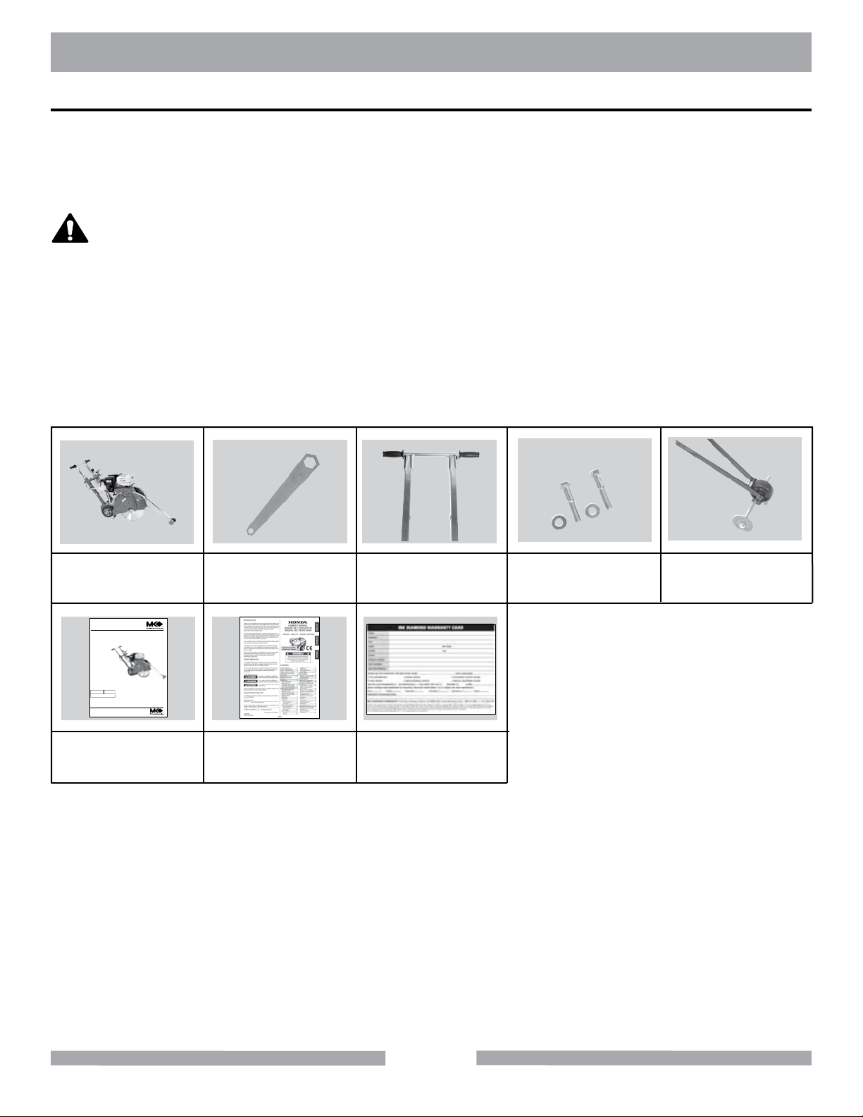
CONTENTS
In the containers, you will nd one (1) MK-1600 Saw, one (1) Blade Nut Wrench, one (1) Handlebar,
two (2) Handlebar Bolts and Washers, one (1) Pointer, one (1) MK-1600 Owner’s Manual, one (1)
Engine Owners Manual, one (1) Warranty Card.
MK-1600
Saw
www.mkdiamond.com
Gas Powered
Concrete Saw
OWNER’S MANUAL &
OPERATING INSTRUCTIONS
MK-1600
Blade Nut
Wrench
Handlebar
Handlebar
Bolts and Washers
Pointer
12.2010
Revision 200
Manual Part# 157841
Caution: Read all safety and operating instructions
before using this equipment. This owner’s manual
MUST accompany the equipment at all times.
MK-1600
Owner’s Manual
Engine Manual Warranty
Card
12
Page 13
MK-1600 TRANSPORT
TRANSPORT
CAUTION
1. The MK-1600 weighs approximately two hundred and thirty-ve (235 pounds),
use care when transporting.
2. Two people are required to lift and transport the MK-1600.
3. A lifting bail is included on Premium models or available as an option.
9
1
8
7
2
5
3
6
4
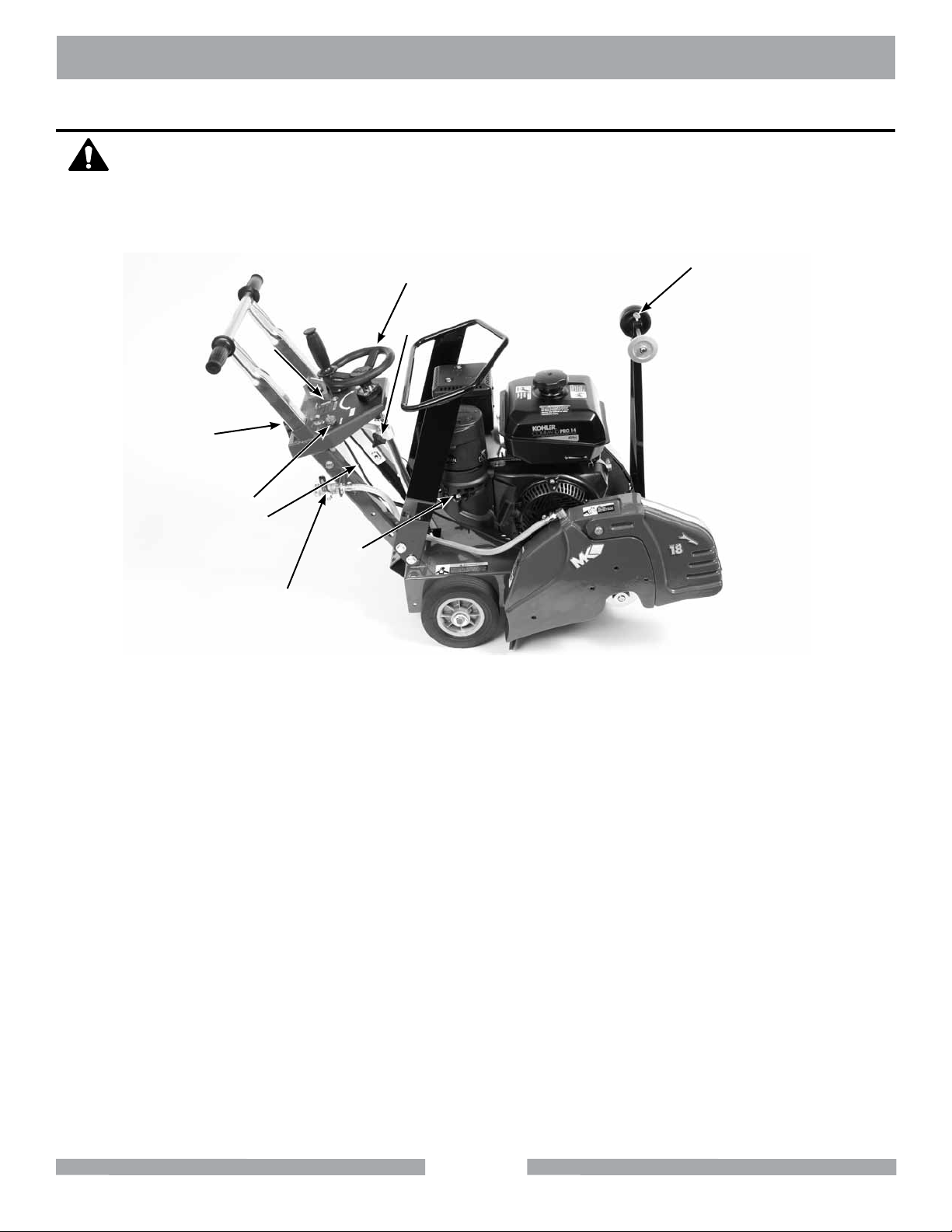
1. The raise lever wheel raises the blade when rotated clockwise, and lowers the blade
when rotated counterclockwise.
2. The raise/lower wheel lock is engaged when the knob is tightened.
3. The throttle control increases engine rpm from slow (idle) at the bottom, to fast (full rpm)
at the top.
4. The water control lever is off in the vertical position and fully on in the
horizontal position. It may be placed at in between settings to regulate the water ow.
5. The engine master switch is located on the console for quick engine shut-off.
6. The choke is located on the engine, by the pull starter, for convenient cold starting.
7. Depth control indicator should be adjusted to zero when setting up saw.
(Premium models only.)
8. Depth control clamp must be adjusted for desired depth of cut.
9. The pointer is set in line at the factory but should be checked for proper alignment with
the blade after every use.
13
Page 14
MK-1600 ASSEMBLY
Follow the assembly instructions to prepare your saw for operation.
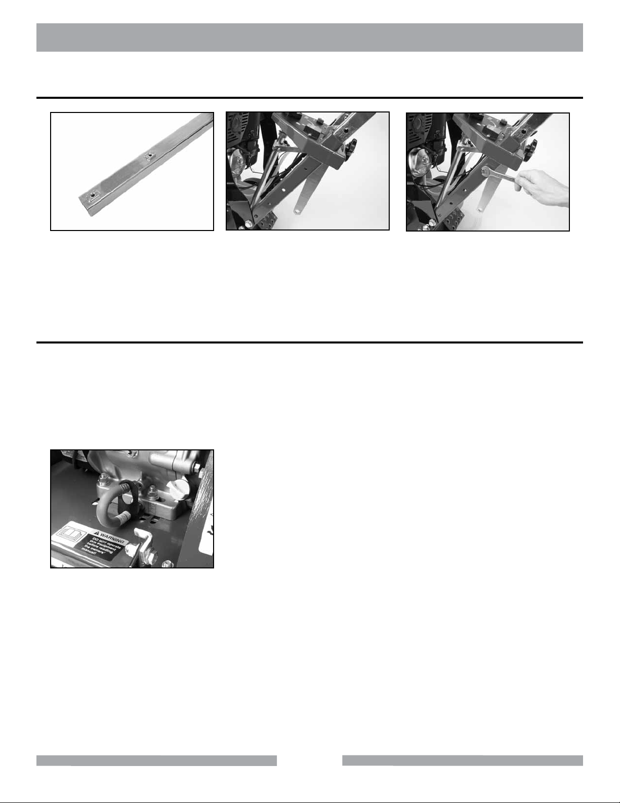
Handlebar Assembly
(A)
Locate the threaded holes on
both sides of the handlebar.
Filling Oil Reservoir
NOTE:
The engine is shipped with no oil in the crankcase. Refer to the engine manual for de-
tails on the type and amount of oil required.
To ll the crankcase with oil, place the engine level. In order for this to be accomplished
the blade must not be installed, and the depth adjustment must be down (until the en-
gine is level).
(B)
Align the handlebar with the
holes on both sides of the
frame at the desired height.
(C)
Install one Washer onto each bolt.
Install bolt through the Handlebar
and into the holes and tighten.
(A)
Verify the Oil Drain Cap is
installed onto the Oil Drain Line
and is tight. Refer to Engine
Manual for details.
14
Page 15

MK-1600 ASSEMBLY
Diamond Blade Installation
NOTE:
1. When installing the blade retaining-bolt, ensure the threads of the bolt are
aligned with the threads of the drive shaft so as not to “cross-thread” the bolt.
2. When installing the blade ensure that the blade shaft and anges are free from dirt
and all foreign material before mounting blade on the blade shaft. Tightening a blade
against an uneven surface can cause fracture or cause the blade to run out of alignment.
3. Blade shaft threads are left-handed on the right side of the saw and right-hand on the
left of the saw.
(A)
Open the Blade Guard Cover.
Locate the Blade Shaft Nut and
the Outer Flange.
(B)
Loosen the Blade Shaft Nut while
holding the Shaft Wrench steady.
(C)
Remove the Blade Nut and
Outer Flange.
(D)
Install the Diamond Blade onto
the Blade Shaft. Ensure direc-
tional arrow on the blade indi-
cates proper rotational direction.
(G)
Tighten Blade Shaft Nut holding
the Blade Shaft steady. Lower
and close Blade Guard.
(E)
Install the Outer Flange. Verify the
drive pin is seated; it must project
through the hole in the blade and
into the ange.
WARNING
Do not operate the saw without the proper
Blade Guard covering. Ensure that the blade
exposure does not exceed 180 degrees during
operation.
15
(F)
Install the Blade Shaft Nut.
Page 16

MK-1600 START UP
Filling Fuel Tank
WARNING
NOTE:
1. Gasoline is highly ammable and explosive. You can be burned or seriously
injured when handling fuel.
2. To fuel, stop engine if running, and allow it to cool.
3. Refuel in a well-ventilated area.
4. Keep gasoline away from appliance pilot lights, barbeques, electric appliances,
power tools, etc.
5. Wipe up spills immediately. Do not start engine until spill is dry.
1. Fuel can damage paint and plastic. Be careful not to spill fuel when lling the
fuel tank. Damage caused by spilled fuel IS NOT covered under the warranty.
2. DO NOT use stale or contaminated gasoline, or an oil/gasoline mixture.
1 inch (25mm)
from throat
Maximum
Fuel Level
Maximum
Fuel Level
(A)
Remove the Fuel Cap. Refer to
Engine Manual for details.
Ensure fuel level is 1” below the
throat of the Fuel Tank.
(B)
(C)
Ensure fuel level is below the
top of the strainer lter.
Pre-Start Inspection
The pre-start inspection should be performed before beginning any job. If Diamond Blade is worn,
replace the blade before starting work.
(A)
Inspect Blade for damage for
cracks. Verify the Blade is cor-
rect for the material being cut.
(B)
Inspect Engine for leaks.
Inspect the saw for general dam-
age and/or loose hardware.
(C)
16
Page 17

MK-1600 STARTUP
Proper Oil Level
Low Level
(D)
Check for proper oil level.
Refer to Engine Manual for
details.
1 inch (25mm)
from throat
Maximum
Fuel Level
(E)
Ensure fuel level is 1” below the
throat of the Fuel Tank.
Maximum
Fuel Level
(F)
Ensure fuel level is below the
top of the strainer lter.
(G)
Check the Air Filter for
cleanliness. Refer to Engine
Manual for details.
Engine Start
WARNING
1. Carbon monoxide gas is toxic, breathing it can cause unconsciousness
and/or death.
2. Avoid any areas or actions that expose you to carbon monoxide.
(A)
Use the Depth Control Wheel to
raise the Blade clear of the oor.
Refer to Engine Manual for start-
ing procedure.
17
Page 18

MK-1600 OPERATION
Front Pointer Alignment
The Front Pointer is set in line at the factory. However, the pointer should be checked for proper
alignment with the blade after every use.
(A)
Using a straight edge, carefully
mark a line 12 feet long on a
smooth level concrete surface.
Place Saw parallel to line; lower
Blade and center it over the line.
Adjusting Depth of Cut Gauge
(A)
Loosen Depth Lock Knob.
(B)
With the Blade centered over the
line and the Saw Frame paral-
lel to the line, lower the front
Pointer assembly and position
the pointer over the line.
(B)
Turn Crank Wheel until Blade
touches the ground.
(C)
Adjust the Pointer in or out if the
orange wheel is off the line by loos-
ening the thumbscrew on the end of
pointer. Align orange wheel with line
and tighten thumbscrew.
(C)
Loosen Depth Indicator Knob and
slide the Depth Control Clamp until
the Depth of Cut Indicator reads
zero.
(D)
Tighten Depth Indicator Knob.
(E)
Tighten Depth Lock Knob.
18
Page 19

MK-1600 OPERATION
Standard Operation
The MK-1600 is intended for industrial applications and operated by experienced professionals. The
operator must be aware of the machine’s capabilities and limitations. It is the operators responsibility
to use this machine under safe working conditions and conform with federal, state and local codes or
regulations pertaining to safety, air, pollution, noise etc...
CAUTION
Prior to operation of this machine the operator must determine the existence and
location of any subsurface features that may be hazardous or could damage the
equipment, (i.e. electric cable, natural gas line etc...)
(A)
Use the Depth Control Wheel to
raise the blade clear of the oor.
(B)
Attach the cooling supply
hose to the Cooling Inlet, if
wet cutting.
(C)
Lower the Pointer. Using a Straight-
edge, align the Pointer to the Blade
see “Front Pointer Alignment.”
(D)
Layout and mark the area to
be cut using a chalk-line. Align
Pointer and Blade to chalk-line.
(G)
With the engine running adjust
the throttle approximately half-
way.
(E)
Place Engine Master Switch in
the “ON” Position.
(H)
For Wet Cutting, open Cooling
Supply Valve. Verify proper cool-
ing ow and adjust the water ow
on the Blade to a desired amount.
19
(F)
Start the Saw using the Engine Start
procedure in the engine manual.
(I)
Move the throttle all the way for-
ward to “Fast” position.
Page 20

MK-1600 OPERATION
NOTE:
Slowly lower the Blade until the
desired level is reached and
Perform the cut using only enough pressure to follow the original marked line. The saw has a
natural tendency to pull towards the side on which the blade is mounted. To assure straight line
cutting, apply pressure to the appropriate handle. If excessive pressure is required reduce the
forward speed of the saw. Driving the saw too fast while cutting may cause the front wheels
to lift causing the blade to cut at uneven depths. Do not attempt to steer the saw. Sudden and
severe corrections can cause the blade to be damaged or broken.
(J)
begin the cut.
(K)
When the cut is complete, raise
the Blade completely out of the
cut by turning Depth Control
Wheel counter-clockwise.
(L)
Close Cooling Supply Valve.
(M)
Move the Throttle Lever to
lower blade speed.
Place Engine Master Switch in
the OFF position. Place Fuel
Valve in the OFF position.
Refer to Engine Manual.
(N)
Dry Cutting
NOTE:
1. Ensure the blade you are using is clearly marked for dry cutting.
2. Check the condition of the air lter at least every four hours of operation.
Refer to Engine Manual for details.
Airow helps to cool the blade during dry cutting. Cutting too deep with one pass, or exerting excessive forward or side pressure can be dangerous and cause damage. Step cut in increments of 2
inches or less, for best results. Thinner blades are especially advantageous when cutting dry.
20
Page 21

MK-1600 CLEANUP
Emergency Engine Shutdown
(A)
Place Engine Master Switch in
the OFF position.
Cleanup
CAUTION
Engine parts are extremely hot following use, allow engine to cool 1/2-hour before
cleaning. Use care during cleanup to avoid injury.
NOTE:
1. To extend operating life, the Concrete Saw should be cleaned following every
use.
2. Using a garden hose or pressure washer is not advised as it can force water
into the air cleaner or mufer opening.
3. Use care when cleaning around electrical components.
(B)
Move the Throttle Lever to lower
blade speed. Place Fuel Valve in
the OFF position.
(A)
Verify the engine is off and cool
before beginning to clean. Clean
the saw with soap and water.
(D)
Clean water system outlets, includ-
ing water tubes in blade guard.
(B)
Clean around the Console.
(E)
Clean the remainder of the exte-
rior surface (except the engine).
21
(C)
Clean the Depth Control Screw
and lubricate as needed.
Page 22

MK-1600 MAINTENANCE
Blade Repositioning
WARNING
Do not operate saw with any guards removed. Turn master engine switch to off
position to avoid accidental starts when removing guards.
(A)
Remove Diamond Blade.
(B)
Remove the Cooling Transfer
Hose from the Blade Guard by
pressing the quick release.
(C)
Locate the four Blade Guard
Retaining Bolts.
(D)
Remove the Blade Guard
Retaining Bolts and remove the
Blade Guard.
(G)
Install the Blade Guard on the
opposite side of the saw.
.
(E)
Locate the Blade Shaft Cover
Retaining Bolts.
(H)
Install Diamond Blade
(F)
Remove the Blade Shaft Cover
Retaining Bolts and the Blade
Shaft Cover.
(I)
Install the Cooling Transfer Hose
from the Blade Guard.
22
Page 23

MK-1600 MAINTENANCE
(J)
Install the Blade Shaft Cover.
(M)
Verify the stop Clip is installed as
shown.
Remove the Pointer.
(K)
(L)
Install the Pointer on the oppo-
site side, next to Blade Guard.
MAINTENANCE SAFETY
• Always turn the master engine switch to the off position.
• NEVER lubricate components or attempt service on a running machine.
• Keep the machinery in proper running condition.
• Fix damage to the machine immediately and always replace broken parts, or missing decals.
New Maintenance
Perform the following after initial purchase and operation of the saw.
(A)
Change engine oil after
rst month or rst 20 operating
hours (See Engine Manual).
Check and adjust tension on
all belts following rst
48 hours of operation
(See Belt section).
(B)
23
Page 24

MK-1600 MAINTENANCE
Maintenance Following Use
The following maintenance should be performed following each use.
(A)
Shut down the Engine. Let saw
cool before proceeding.
(D)
Lubricate the pivot point of the
Pointer.
(See Engine Manual).
Lubricate the Cooling
(B)
Check Air Filter
(E)
Supply Valve.
(C)
Lubricate the Grease Fitting.
(F)
Verify the tightness of all bolts
and screws. Clean the saw (ex-
cept the engine) with soap and
water.
Weekly (50 hours) and Monthly (200 hours)
The following should be performed monthly. Items should be lubricated using waterproof grease.
(A)
Change engine oil every 100
hours. Refer to Engine Manual
for details.
(B)
Lubricate the Depth Control
Screw (Monthly).
24
(C)
Lubricate the Blade Shaft Bear-
ings (Monthly).
Page 25

MK-1600 MAINTENANCE
(D)
Clean engine Air Filter weekly
and replace monthly. Refer to
Engine Manual for details.
Clean Spark Plug Weekly and
readjust Spark Plug monthly.
Refer to Engine Manual for
NOTE:
(G)
Clean and lubricate the Blade
Retaining Bolt.
500 Hours and 1000 Hour Maintenance
(E)
Clean and lubricate the Blade
details.
(F)
Shaft.
Denitive information on engine maintenance is
contained in the engine manual provided separately. Perform all maintenance procedures as
recommended by the engine manual.
Perform the following maintenance every 500 hours.
(A)
Replace Spark Plug. Refer to
Engine Manual for details.
Have Authorized Repair Shop
perform 500-hour
(B)
maintenance.
25
(C)
Have Authorized Repair Shop
perform 1000-hour maintenance.
Page 26

MK-1600 MAINTENANCE
Yearly and Two-Year Maintenance
Perform the following maintenance every year.
(A)
Inspect belts for proper tension
and wear.
Check Fuel Level
For all Engine related maintenance and troubleshooting refer to the Engine Manual.
WARNING
1. Gasoline is highly ammable and explosive. You can be burned or seriously
injured when handling fuel.
2. To fuel, stop engine if running and allow it to cool.
3. Refuel in a well-ventilated area.
4. Keep gasoline away from appliance pilot lights, barbeques, electric appliances,
power tools, etc.
5. Wipe up spills immediately.
NOTE:
1. Fuel can damage paint and plastic. Be careful not to spill fuel when lling the
fuel tank. Damage caused by spilled fuel IS NOT covered under the warranty.
2. DO NOT use stale or contaminated gasoline or an oil/gasoline mixture.
1 inch (25mm)
from throat
Maximum
Fuel Level
Maximum
Fuel Level
(A)
Remove the Fuel Cap. Refer to
Engine Manual for details.
(B)
Ensure fuel level is 1” below the
throat of the Fuel Tank.
26
(C)
Ensure fuel level is below the
top of the strainer lter.
Page 27

MK-1600 MAINTENANCE
Checking Oil Level
NOTE:
When installing the Oil Dipstick, ensure the threads
are aligned with the threads of the Oil Reservoir so
as not to “cross-thread.”
(A)
Verify the Engine is upright and
level. Refer to Engine Manual
for details.
Engine Maintenance
Engine maintenance and adjustment is necessary to keep the saw in good operation condition. Maintenace operations include oil changes, lter changes, air cleaner, spark plug, fuel lter etc...Perform
all maintenance procedures as recommended by the Honda, Kohler or Subaru engine manual pro-
vided separately.
(A)
Remove the Diamond Blade.
See Blade removal section.
Lower the MK-1600 to its
(B)
lowest position.
Engine Air Filter Inspection Cleaning and Replacement
(A)
Clean the Air Filter. Refer to
Engine Manual for details.
27
(C)
Free the Oil Drain Line.
Place a catch basin below the
Oil Drain Line. Remove the Drain
Cap to drain oil completely. Refer
to Engine Manual for details.
Page 28

MK-1600 MAINTENANCE
Spark Plug Adjustments and Replacement
For all Engine related maintenance and troubleshooting refer to the Engine Manual.
CAUTION
(A)
When installing the Spark Plug,
ensure the threads are aligned with
the threads in the engine so as not to
“cross-thread” the plug.
DO NOT work around the engine while hot.
Diamond Blade Removal
(A)
Open the Blade Guard Cover.
(D)
Install the new Blade, Retaining
Bolt and Outer Flange.
(B)
Remove the Blade Shaft Nut and
the Outer Flange.
(E)
Tighten Blade Retaining Bolt
while holding the Blade Shaft
steady.
28
(C)
Remove blade.
Page 29

MK-1600 MAINTENANCE
Belt Adjustment and Replacement
In order to ensure the saw operates at peak efciency, the power transmission belt should be inspected
monthly and changed if any signs of damage and/or excessive wear is observed.
NOTE: 1. When a new belt is installed, it should be inspected and retensioned after the rst
forty-eight (48) hours of operation.
2. Do not over tension belts as damage to belts and bearings may occur. Belts that are
too loose may slip, resulting in short life of loss of power to the blade shaft. If any belts
are worn or damaged, replace complete set.
(A)
Remove the Blade
(See Blade Removal section).
(D)
Check belt for proper tension if tension is correct, go to Step P (Proper
tension is approximately 1/8-inch
deection of the belt).
(B)
Locate and remove the Belt
Guard Retaining Bolts and then
remove the Belt Guard.
(E)
Locate the four upper Engine
Mounting Nuts on both ends of
the motor and loosen.
(C)
Inspect the belt for excessive
wear, cracks and cuts – if worn,
proceed to Step E.
(F)
Locate the four lower Engine
Mounting Bolts on both ends of
the motor and loosen.
(G)
Loosen Jam Nut on Engine
Tension Arm.
(H)
Loosen the Engine Tension Arm
adjusting nut. Push the Engine
forward to loosen the belt.
29
(I)
Remove the old belts from the
Engine and Blade Shaft Pulleys.
Page 30

MK-1600 MAINTENANCE
(J)
Clean and verify the alignment
of the Engine and Blade Shaft
Pulleys.
(M)
Tighten the Engine Tension Arm
Nuts.
(K)
Install new belts onto the Engine
Blade Shaft Pulleys.
(N)
Check belt for proper tension
(Proper tension is approxi-
mately 1/8-inch deection of the
belt).
(L)
Verify the belts are seated in all
grooves of the Engine and Blade
Shaft Pulleys.
(O)
Repeat Steps L and M until
proper tension is achieved.
(P)
Tighten the Engine Mounting
Bolts.
(Q)
Install the Belt Guard and Belt
Guard Retaining Bolts.
30
(R)
Install the Blade (See Blade
Installation section).
Page 31

MK-1600 TROUBLESHOOTING
TROUBLESHOOTING
When trouble occurs, be sure to check the simple causes which, at rst, may seem too obvious to be
considered. Refer to the table below for problems and their possible causes.
ENGINE
OTHER
Cause
No Fuel
Problem
Will not start X X X X X
Hard starting X X X X X
Stops suddenly X X X X
Lacks power X X X X X
Operates erratically X X X X
Knocks or pings X X
Skips or misres X X X
Back res X X X
Overheats X X
High Fuel Consump-
tion
Cause
Problem
Reduced blade life X X
Improper Blade for the
Improper
Fuel
Application
Dirt in
Fuel Line
Improper Belt
Tension
Incorrect
Oil Level
Dirty Air
Filter
X X
Damage Caused by
External Objects
Faulty
Spark
Plugs
Excessive belt wear X X
31
Page 32

NOTES
32
Page 33

NOTES
33
Page 34

MK-1600 EXPLODED VIEW
34
Page 35

MK-1600 EXPLODED VIEW
35
Page 36

MK-1600 EXPLODED VIEW
36
Page 37

MK-1600 PARTS LIST
Item Description Qty
A1 Owner’s Manual, MK-1600 1 157841
A2 Warranty Card 1 155859
A3 Wrench 1 137976
A4 Key, 1/4 Hex 1 156235
B1 Belt Guard 1 157704
B2 Washer, 5/16 SAE Flat 3 151754
B3 Washer, 5/16 Split Lock 3 151747
B4 Screw, 5/16-18 X 1 Hex Head Cap 1 151743
B5 Screw, 5/16-18 X 3/4 Hex Head Cap 2 151369
B6 Back Plate, Belt Guard 1 157705-DD
B7 Washer, 1/4 SAE Flat 1 151915
B8 Washer, 1/4 split lock 1 152591
B9 Screw, 1/4-20 X 1/2 Hex Head Cap 1 152608
B10 Screw, 3/8-16 X 3/4 Hex Head Cap 1 153527
B11 Washer, 3/8 SAE Flat 1 150923
B12 Washer, 3/8 Split Lock 1 150925
B13 Belt, 3VX280 3 160615
B14 Label, Caution, Belt Tension, 1.5 X 3.0 1 155583
B15 Label, Caution, Guards in Place, 1.5X3.0 1 155587
B16 Label, Caution, Sparkplug 1 155579
C1 18” Rear Blade Guard 1 159544
C2 18” Front Blade Guard 1 159645
C3 Screw, 3/8-16 X 4 Hex Head Cap 1 153531
C4 Washer, 3/8 SAE Flat 6 150923
C5 Nut, 3/8 - 16 X Nylock Hex 1 152505
C6 Nut, 3/8 - 16 X 1 Hex Head Cap 4 152507
C7 Washer, 3/8 split Lock 4 150925
C8 Fitting, Brass, 1/8 MNPT X Barb 1 152501
C9 Flap, Rubber Splash 1 150846
C10 Screw, 1/4 - 20 X 1/2 Hex Head Cap 2 152608
C11 Washer, 1/4 SAE Flat 4 151915
C12 Washer, 1/4 Split Lock 2 151893
C13 Nut, 1/4 - 20 Hex 2 151893
C14 Label, Caution, Lift Guard, 1.5 x 3.0 1 155586
C15 Label, Blade Failure Warning 1 155588
D1 Nut, Blade Shaft, 3/4 - 16 Left Hand 1 155069
D2 Flange, Inner, Left Hand 1 155068
D3 Bearing, 1” Pillow Block 2 155072
D4 Shaft, Blade, Premium 1 157842
D5 Screw, 7/16 - 14 X 1-1/2 Hex Head Cap 4 155155
D6 Washer, 1/2 SAE Flat 4 150924
D7 Pulley, 2 Groove, 3-1/4 x 1 Balde Shaft 1 160613
D8 Screw, 5/16-18 X 1/4 Socket Head Set 2 152607
D9 Key, Square, 1/4 X 1/4 x 1 ¾ 1 150796
D10 Flange, Inner, Right Hand 1 157843
D11 Nut, Blade Shaft, 3/4 - 16 Right Hand 1 157844
D12 Nut, 7/16 - 14 Hex 4 150922
D13 Washer, 7/16 Split Lock 4 151051
D14 Washer, 7/16 SAE Flat 2 151050
D15A Pin, 3/8 X 1 Type “A” Groove 1 152207
D15B Flange, Outer 1 150732
F1 Depth Control Wheel 1 155156
F2 Screw, 3/8 - 16 X 1/2 Socket Head Set 1 153710
F3 Handle, Depth Control Wheel 1 156236
F4 Handgrip 1 150842
F5 Screw, 1/2 X 3/4 Socket Head Shoulder w/ 3/8-16 X 5/8 Thread 1 156177
F6 Tube, Depth Control 1 155049
Part#
37
Page 38

MK-1600 PARTS LIST
Item Description Qty
F7 Nut, 3/8-16 Nylock Hex 1 152505
F8 Screw, 3/8-16 X 2 Hex Head Cap 1 153485
F9 Bearing, Flange, w/ zerk fitting 1 155151
F10 Screw, 3/8-16 X 1 1/4 Hex Head Cap 2 150774
F11 Nut, 3/8-16 Nylock Hex 2 152505
F12 Spacer, Depth Control 1 155161
F13 Nut, 3/4-10 Hex 1 155063
F14 Screw, Depth Control 1 155062
G1 Screw, 1/4 - 20 X 1/2 Pan Head Phillips Cap 1 152517
G2 Bracket, Depth Indicator 1 156608
G3 Nut, 1/4 - 20 Hex 1 151893
G4 Arm, Depth Indicator 1 156604
G5 Washer, 1/4 Split Lock 2 152591
G6 Clamp, Depth Indicator 1 156604
G7 Washer, 5/16 SAE Flat 1 151754
G8 Knob, Davies 1 151681
G9 Screw, 8 - 32 X 1/2 Pan Head Phillips Cap 1 152517
G10 Washer, #8 SAE Flat 2 155454
G11 Nut, 8 - 32 Hex 1 152549
G12 Spring, Depth Indicator 1 156605
G13 Spool, 1.0 Depth Indicator 1 157845
G14 Screw, 1/4 - 20 X 1 - 1/2 Hex Head Cap 1 152517
G15 Washer, 1/4 SAE Flat 1 151915
H1 Lock, 8 - 7/8 Depth Control 1 157846
H2 Knob, Depth Lock 1 155845
H3 Thrust Washer 1 155845
H4 Nut, 3/8 - 16 Nylock Hex 1 152505
J1 Engine, Honda GX390 13hp w/ Cyclone Air Filter 1 155365
JA1 Engine, Kohler command Pro CS 12 hp (not shown) 1 157831
JB1 Engine, Honda 8 Hp w/Cyclone Air Filter 1 155133
J2 Label, Caution, Hot Surface, 1.5 x 3.0 1 155578
J3 Label, Warning, Refueling, 1.5 X 3.0 1 155580
J4 Label, Danger, California, 1.5 X 3.0 1 155581
J5 Label, Danger, Lethal Exhaust, 1.5 X 3.0 1 155582
J6 Screw, 5/16-18 X 1/4 Socket Head Set 2 152607
J7 Key, Square, 1/4 X 1/4 x 1 ¾ 1 150796
J8 Pulley, 2 Groove, 3/14 X 1 Engine Pully 1 160614
J9 Nut, 3/8-16 Hex 4 101188
J10 Washer, 3/8 Split Lock 4 150925
J11 Washer, 3/8 SAE Flat 7 150923
J12 Plate, Engine Bolt 2 157847
J13 Screw, 3/8-16 X 2 Hex Head Cap 4 153485
J14 Pin, Throttle Control 1 151284
J15 Screw, 8-32 X 3/8 Pan Head Cap 1 156614
J16 Pin, Cotter, 1/16 X ¾ 1 152518
J17 Plug, Plastic, 3/4 Round 1 156615
J18 Deflector, Honda 11/13HP 1 155375
J19 Screw, 6-32 X 1/2 Pan Head Phillips Self-tapping Cap 3 153466
J20 Oil Drain, Sub-assembly Adapter, M12-1.5 x 3/8 Push 1 157577-02
K1 Frame 1 157836-DD
K2 Arm, Tension 1 157848
K3 Washer, 5/16 SAE Flat 2 151754
K4 Nut, 5/16-18 Hex 2 101196
K5 Label, Private Label Serial Number 1 157458
K6 Label, Console 1 159950
K7 Label, Depth Lock, 1.04 X 3.25 1 155577
K8 Label, Operating Instructions, 3.5 X 6.0 1 155584
K9 Label, Caution, Hands and Feet, 2.0 X 4.0 1 155585
Part#
38
Page 39

MK-1600 PARTS LIST
Item Description Qty
L1 H a n d l e b a r 1 159903
L2 H a n d gr i p , N e o pr e n e 2 157855
L3 Handlebar Plugs 2 156615
L4 Screw, 3/8-16 X 2 Hex Head Cap 2 153485
L5 Washer, 3/8 SAE Flat 2 150923
M1 Arm, Pointer 1 156544
M2 Pointer 1 155057
M3 Wheel, Pointer 1 155066
M4 Screw, 1/4-20 X 3/4 Thumb 2 150991
M5 Clip, Stop 1 157837
M6 Screw, 3/8-16 X 1 1/2 Hex Head Cap 2 153528
M7 Washer, 3/8 SAE Flat 4 150923
M8 Nut, 3/8-16 Nylock Hex 2 152505
N1 Guard, Shaft 1 156307
N2 Washer, 3/8 SAE Flat 3 150923
N3 Washer, 3/8 Split Lock 3 150925
N4 Screw, 3/8-16 X 1 Hex Head Cap 3 152507
N5 Label, Caution, Guards in Place, 1.5X3.0 1 155587
P1 Tachometer/ Hour meter 1 153877
P2 Screw, 8 - 32 X 1/12 Pan Head Phillips Self-Tapping Cap 2 156632
P3 Wire Harness, Premium, Honda (not Shown) 1 156633
P4 Switch, Engine On/Off 1 157851
Q1 Screw, 10-24 X 1/2 Pan Head Phillips Cap 2 151744
Q2 Nut, 10-24 Clip 2 155407
Q3 Assembly, Throttle Head 1 155406
Q4 Cable, Throttle, Honda 1 154158
R1 Truck 1 155048
R2 Wheel, Rear, 8 X 2 ¼ 2 155986
R3 Wheel, Front, 4 X 1 ½ 2 150830
R4 Washer, 3/4 SAE Flat 4 153523
R5 Washer, 3/4 Shim 6 153699
R6 Screw, 1/2 X 1/2 Socket Head Shoulder, w/ 3/8-16 X 5/8 Thread 2 151753
R7 Nut, 3/8-16 Hex 2 101188
R8 Washer, 3/8 Split Lock 2 150925
R9 Washer, 3/8 SAE Flat 3 150923
R10 Washer, 1/2 SAE Flat 2 150924
R11 Pin, Cotter, 1/8 X 1 1/2 4 153861
S Assembly, Water Valve 1 155458
S1 Fitting, Brass, 1/2 MNPT X Garden Hose Swivel 1 151322
S2 Valve, Shut-Off, 1/2 FNPT X 1/2 FNPT 1 150843
S3 Nut, 1/2 NPT 1 152729
S4 Fitting, Brass, 1/2 MNPT X 3/8 BARB 1 153653
S5 Clamp, 5/8 Hose 2 151198
S6 Hose, 3/8 ID Vinyl 30” 150845
T Assembly, Lifting Bail (premium only) 1 157853
T1 Lifting Bail 1 157745
T2 Screw, 1/2-13 X 1 1/4 Hex Head Cap 4 153532
T3 Washer, 1/2 Split Lock 4 153524
T4 Washer, 1/2 SAE Flat 8 150924
T5 Nut, 1/2-13 Hex 4 151282
U Assembly, Water Tank (optional) 1 157852
U1 Tank, Water 1 156644
U2 Cap 1 156956
U3 Valve, Shut Off 1 152075
U4 Elbow, 90° 1 152074
U5 Fitting 1 152076
U6 Tee, 3/8 Hose Barb, Brass 1 156645
U7 Hose, 3/8 I.D. Vinyl 2’ 150845
U8 Hose Clamp, 3/8 4 151198
Part#
39
Page 40

MK-1600
THEORY
THEORY OF DIAMOND BLADES
Diamond blades do not really cut; they grind the material through friction. Diamond crystals, often
visible at the leading edge and sides of the rim/segment, remove material by scratching out particles of hard, dense materials, or by knocking out larger particles of loosely bonded abrasive material. This process eventually cracks or fractures the diamond particle, breaking it down into smaller
pieces. As a result, a diamond blade for cutting soft, abrasive material must have a hard metal
matrix composition to resist this erosion long enough for the exposed diamonds to be properly utilized. Conversely, a blade for cutting a hard, non-abrasive material must have a soft bond to ensure
that it will erode and expose the diamonds embedded in the matrix. These simple principles are the
foundation of “controlled bond erosion”
Types of Cutting
There are two basic types of cutting-Dry or Wet. The choice of which type of blade to use depends
on:
• The requirements of the job
• The machine/tool utilizing the diamond blade
• The preference of the operator
In the case of DRY cutting, the overwhelming popularity and quantity of hand-held saws and the
exible nature of MK Diamond blades to professionally handle most ceramic, masonry, stone and
concrete materials, make the DRY cutting blade a very attractive tool. When using a DRY blade,
the user must be aware of distinct operating practices to ensure optimum performance. DRY cutting
blades require sufcient airow about the blade to prevent overheating of the steel core. This is best
accomplished by shallow, intermittent cuts of the material with periods of “free-spinning” (for several
seconds) between each cut, to maximize the cooling process.
For WET cutting applications, MK has the exact blade to compliment both the material to be cut and
the wet cutting machine to be used. During cutting operations, liberal amounts of water act as a
coolant to support the cutting effectiveness and longevity of the WET blade. Additionally, using water
adds to the overall safety of cutting operations by keeping the dust signature down.
Know All You Can About the Material You Wish to Cut
40
Page 41

MK-1600 ACCESSORIES
ACCESSORIES
ITEM NUMBER DECRIPTION
MK-500
1
2
3
134965
129072
134965
18” x .125 x 1”
Standard grade wet cutting
blade for cured concrete
MK-505
18” x .125 x 1”
Premium grade, wet cutting
blade for cured concrete
MK-525
18” x .125 x 1”
Supreme grade, wet cutting
blade for cured concrete
MK-705W
4
5
6
7
133850
139162
153550
157852
18” x .142 x 1”
Premium grade, wet cutting
blade for asphalt
MK-610W
18” x .142 x 1”
Supreme grade, wet cutting
blade for green concrete
MK-465D
18” x .142 x 1”
Premium grade, dry cutting
blade for asphalt and green
concrete
6.5 Gallon
Water Tank
8
157745 Lifting Bail
41
Page 42

MK-1600 ORDERING & RETURN
ORDERING INFORMATION
You may order MK Diamond products through your local MK Diamond distributor or, you may order
direct from MK Diamond.
When ordering direct from MK Diamond, please have the following information ready before calling:
• The Model Number of the saw
• The Serial Number of the saw
• Where the saw was purchased and when
• The Part Number for the part(s) being ordered
• The Part Description for the part(s) being ordered
NOTE: There is a $25.00 minimum order when ordering direct from MK Diamond. A $5.00 charge will
be added to orders having a net billing value under $50.00. All purchases must be made using VISA,
MasterCard or American Express.
All parts may be ordered by calling toll free to – 800 421-5830 or 310 539-5221 and asking for
Customer Service. For technical questions, call – 800 474-5594.
RETURN MATERIALS POLICY
To expedite the service relative to the return of a product purchased through MK Diamond, please
observe the following:
NOTE: When returning all items, they must have been purchased within the previous twelve (12)
months.
• Have the Model Number of the saw
• Have the Serial Number of the saw
• Have the location of where the saw was purchased
• Have the date when the saw was purchased
• Contact Customer Service for approval to return the item(s)
• Obtain a Returned Goods Number (RGA) authorizing the return
• Follow the packaging instructions in the following section
• Ensure your item(s) are prepaid to the destination
For returned items, call toll free to – 800 421-5830 or 310 539-5221 and ask for Customer Service.
For technical questions, call – 800 474-5594 or 310 257-2845.
PACKAGING INSTRUCTIONS
• Remove the Cutting Head and Support Angle Assembly
• Dry the saw before shipping
• When packing, include the following: Saw, Diamond Blade, Blade Guard and Support Angle
Assembly and Adjustable Cutting Guide (Other Accessories are not required)
• Package the unit in its original container or one of comparable size (do not ship the unit partially
exposed)
• Ensure all parts are secured in the packaging to prevent moving
AUTHORIZED SERVICE CENTERS
For quicker repair time, you may contact MK Diamond Customer Service, toll free, at 800 421-5830
or 310 539-5221 for the Authorized Service Center closest too you or visit our web site at
www.mkdiamond.com. For technical questions, call – 800 474-5594.
42
Page 43

MK-1600 WARRANTY
CONTACT:
Please contact MK Diamond Products, Inc. Customer Service Department with any questions you
might have regarding distributors, parts or service.
Telephone: (800) 421-5830
Fax: (310) 539-5158
E-mail: Customer_Service@MKDiamond.com
Customer Service Hours: Monday through Friday, 6AM-4PM PST
MK Diamond Products, Inc.
1315 Storm Parkway
Torrance, CA 90501
MK DIAMOND PRODUCTS, INC. LIMITED WARRANTY
MK DIAMOND PRODUCTS, INC. will guarantee every machine they build, to be free from defects in
material and workmanship for (1) one year from date of purchase. The obligation of MK DIAMOND
PRODUCTS, INC. under this warranty is limited to the repair or replacement of any parts which,
under normal use, prove to be defective in material or workmanship. The parts involved or the unit
in question should be returned to MK DIAMOND PRODUCTS, INC. or to a point designated by us,
transportation prepaid.
This warranty does not obligate us to bear the cost of labor or transportation charges in connection
with replacement or repair of defective parts. Likewise, it shall NOT apply to any unit which has been
subjected to misuse, neglect or accident. This warranty does NOT apply to any machine which has
been repaired or altered outside our factory.
This warranty does NOT obligate MK DIAMOND PRODUCTS, INC., with respect to items not of our
manufacture, such as engines, motors, hydraulics, etc., which are subject to their own guarantees and
warranties.
We shall in no event be liable for consequential damages or contingent liabilities arising out of failure
of any equipment or parts to operate properly.
© COPYRIGHT 2012, MK DIAMOND PRODUCTS, INC. ALL RIGHTS RESERVED.
The MK Diamond logo is a registered trademark of MK Diamond Products, Inc. and may not be used,
reproduced, or altered without written permission. All other trademarks are the property of their re-
spective owners and used with permission.
MK Diamond may have patents, patent applications, trade marks, copyrights of other intellectual
property right covering this product in this document.
This manual MUST accompany the equipment at all times. This manual is considered a permanent
part of the equipment and should remain with the unit if resold.
The information and specications included in this publication were in effect at the time of approval for
printing.
43
Page 44

MK-1600 CONCRETE SAW
OWNERS MANUAL & OPERATING INSTRUCTIONS
MK Diamond Products, Inc.
1315 Storm Parkway
Torrance, CA 90501
Toll-Free: (800) 421-5830
Phone: (310) 539-5221
Fax: (310) 539-5158
www.mkdiamond.com
 Loading...