

Page 1

www.mkdiamond.com
MK DIAMOND
TRACK RAIL SAW
OPERATION & PARTS MANUAL
03.2012Revision 302
Manual Part No. 166110
Caution: Read all safety and operating instructions
before using this equipment. This manual MUST
accompany the equipment at all times.
Page 2
TRACK RAIL SAW INTRODUCTION
Congratulations on your purchase of a Track Rail Saw. We are certain that you will be pleased with
your purchase. MK Diamond takes pride in producing the nest construction power tools and diamond blades in the industry.
Operated correctly, your Track Rail Saw should provide you with years of service. In order to help
you, we have included this manual. This owners manual contains information necessary to operate
and maintain your Track Rail Saw safely and correctly. Please take the time to familiarize yourself
with the Track Rail Saw by reading and reviewing this manual.
Read and follow all safety, operating and maintenance instructions.
If you should have questions concerning your Track Rail Saw, please feel free to call our friendly customer service department at: 800 421-5830
Regards,
MK Diamond
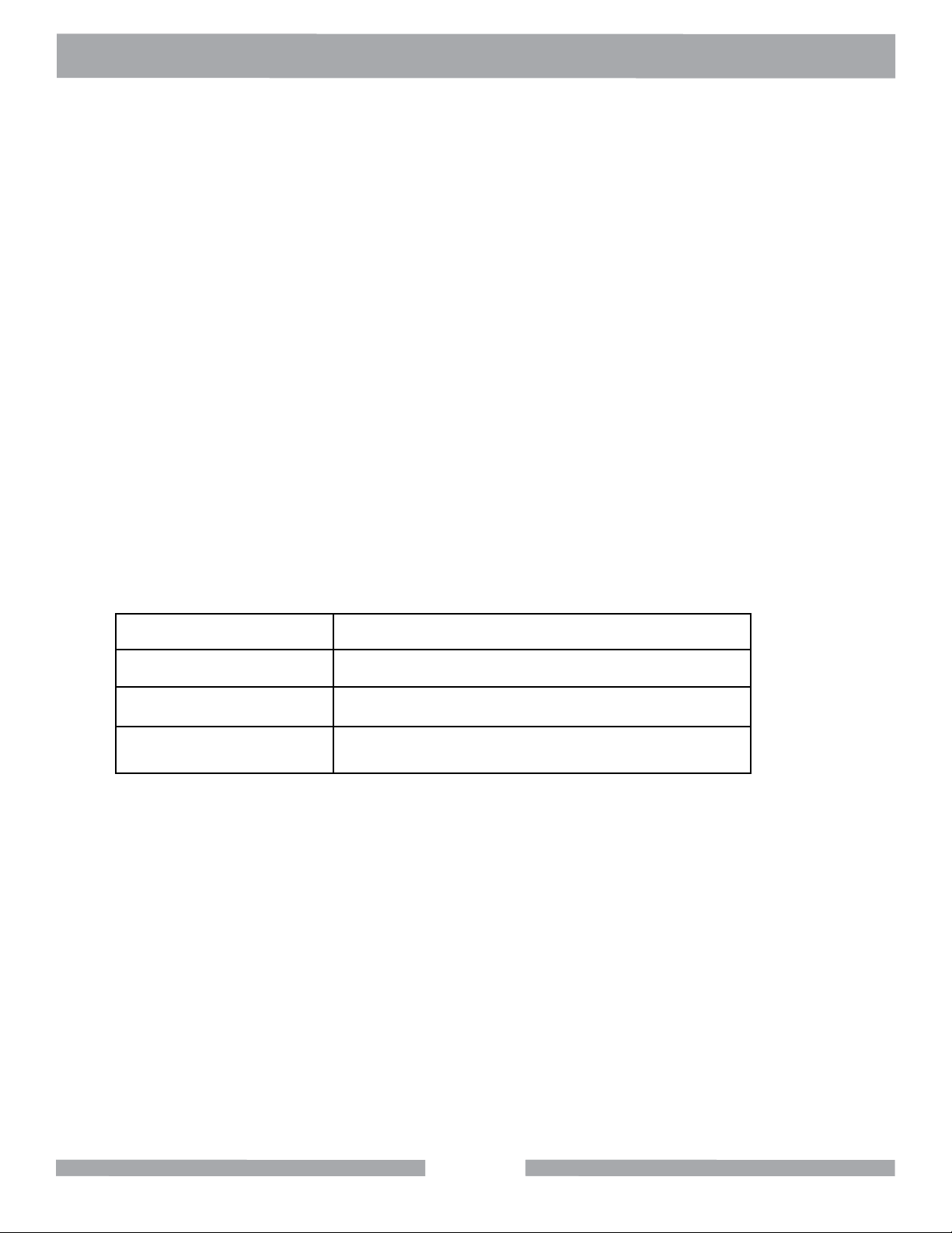
NOTE THIS INFORMATION FOR FUTURE USE:
MODEL NUMBER:
SERIAL NUMBER:
PURCHASE PLACE:
PURCHASE DATE:
NOTE: For your (1) one year warranty to be effective, complete the warranty card
(including the Serial Number) and mail it in as soon as possible.
22
Page 3

TRACK RAIL SAW TABLE OF CONTENTS
MK DIAMOND TRACK RAIL SAW
SAFETY
Safety Message/Alert Symbols
Safety Warnings
Hazard Symbols
Electric Motor Safety
Rules for Safe Operation
Operation & Safety Decals
PRODUCT SPECIFICATIONS
Specications
SET-UP
Rail Assembly
Rail Assembly Connector
Cutting Head Assembly
Material Clamps & Alignment
Hose Set-Up
OPERATION
Plunge Cutting for a 90º Cut
Plunge Cutting for a Miter Cut
PAGE NO.
4
5
6
7
8-9
10
11
12
13
14
15
16
17
18
MAINTENANCE
Blade Replacement
Filter Replacement
Roller Wheel Replacement
GENERAL PRODUCT INFORMATION
Parts List: Final Assembly
Parts List: Main Carrier Assembly
Parts List: Cutting Head Assembly
Parts List: Blade Guard Assembly
Parts List: Parallel Rail Support Bracket
Parts List: Rail Connector Plate
Parts List: Rail Saw Material Clamp
Ordering Information
Contact Information and Limited Warranty
19
20
21-23
24-25
26-27
28-29
30
31
32
33
34
35
3
Page 4
TRACK RAIL SAW SAFETY
Safety precautions should be followed at all times when operating this equipment. Failure to read and
understand the Safety Precaution and Operating Instructions could result in injury to yourself and
others.
This Operation Manual has been developed to provide complete instructions for the safe and efcient
operation of the CX-3
®
Concrete Saw.
Before using this saw, ensure that the person operating the equipment has read and understands all
instructions in this manual.
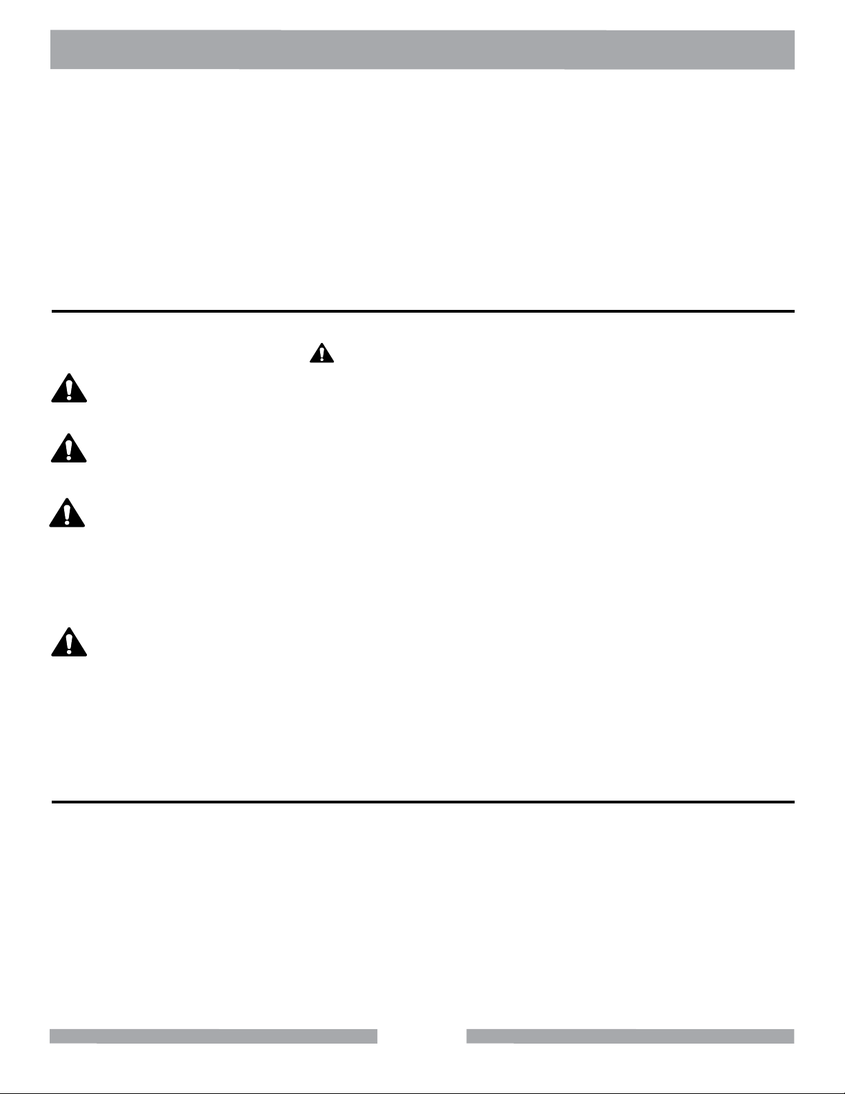
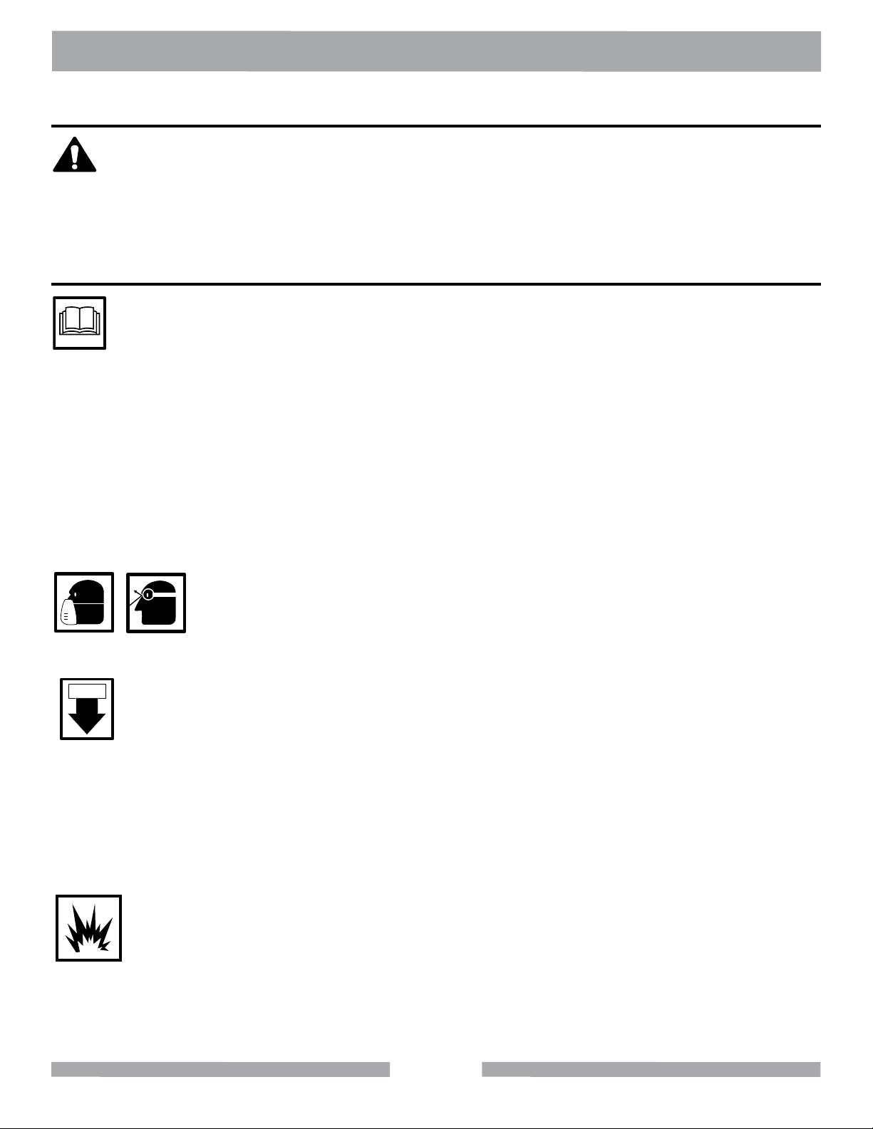
SAFETY MESSAGE / ALERT SYMBOLS
A safety message alerts you to potential hazards that could hurt you or others. Each safety message is
preceded by a safety alert symbol ( ) and one of three words: DANGER, WARNING, or CAUTION.
DANGER
You WILL be KILLED or SERIOUSLY INJURED if you do not follow directions.
WARNING
You CAN be KILLED or SERIOUSLY INJURED if you do not follow directions.
CAUTION
You CAN be INJURED if you do not follow directions. It may also be used
to alert against unsafe practices.
Each message tells you what the hazard is, what can happen, and what you can do to avoid or
reduce injury. Other important messages are preceded by the word NOTICE.
NOTICE
You can cause PROPERTY DAMAGE to your machine if you don’t follow directions.
The safety labels should be periodically inspected and cleaned by the user to maintain good legibility
at a safe viewing distance. If the label is worn, damaged or illegible, it should be replaced. Contact
MK Diamond or your dealer for replacement.
DAMAGE PREVENTION AND INFORMATION MESSAGES
A Damage Prevention Message is to inform the user of important information and/or instructions that
could lead to equipment or other property damage if not followed. Information messages convey
information that pertains to the equipment being used. Each message will be preceded by the word
note, as in the example below.
NOTE: Equipment and/or property damage may result if these instructions are not followed.
4
Page 5

TRACK RAIL SAW SAFETY
SILICA DUST WARNING
Grinding/cutting/drilling of masonry, concrete, metal and other materials with silica in their composition
may give off dust or mists containing crystalline silica. Silica is a basic component of sand, quartz,
brick clay, granite and numerous other minerals and rocks. Repeated and/or substantial inhalation of
airborne crystalline silica can cause serious or fatal respiratory diseases, including silicosis. In addition, California and some other authorities have listed respirable crystalline silica as a substance
known to cause cancer. When cutting such materials, always follow respiratory precautions.
CALIFORNIA PROPOSITION 65 MESSAGE
Some dust created by power sanding, sawing, grinding, drilling, and other construction activities contain chemicals known (to the State of California) to cause cancer, birth defects or other reproductive
harm. Some examples of these chemicals are:
• Lead, from lead-based paints
• Crystalline silica, from bricks and cement and other masonry products
• Arsenic and chromium, from chemically treated lumber
For further information, consult the following sources:
http://www.osha.gov/dsg/topics/silicacrystalline/index.html
http://www.cdc.gov/niosh/consilic.html
http://oehha.ca.gov/prop65/law/P65law72003.html
http://www.dir.ca.gov/Title8/sub4.html
Your risk from these exposures varies depending on how often you do this type of work. To reduce
your exposure to these chemicals, work in a well-ventilated area, and work with approved safety
equipment, such as those dust masks that are specially designed to lter out microscopic particles.
5
Page 6
TRACK RAIL SAW SAFETY
Potential hazards associated with the MK Diamond Track Rail Saw will be referenced with Hazard
Symbols which appear throughout this manual, and will be referenced in conjunction with Safety Message Alert Symbols.
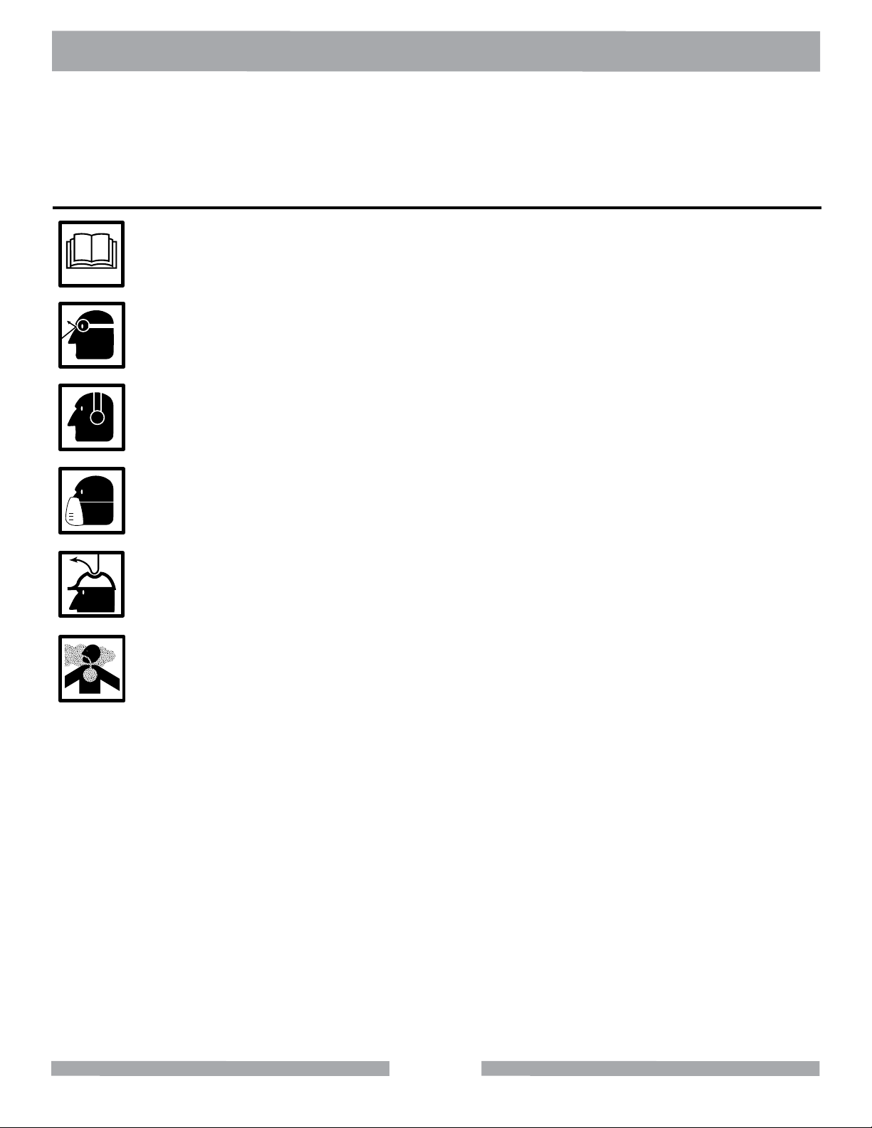
HAZARD SYMBOLS
ALWAYS read this Owner’s Manual before operating the machine.
ALWAYS wear approved eye protection.
ALWAYS wear approved ear protection.
ALWAYS wear approved respiratory protection.
ALWAYS wear a hard hat.
ALWAYS avoid inhalation of and skin contact with silica dust and/or mist.
6
Page 7
TRACK RAIL SAW SAFETY
WARNING
DO NOT use woodcutting, or carbide blades on this machine! Use ONLY Diamond blades on ma-
chine. Use machine only to cut tile and masonry products. DO NOT use machine to cut wood or wood
products.
ELECTRIC MOTOR SAFETY
For maintenance care and operation of the electric motor, refer to your electric motor instruction booklet
furnished with the electric motor.
Protect the electric motor from dust as much as possible and keep ventilating openings clean.
CAUTION
DO NOT spray water at any time on the electric motor.
•
DO NOT operate electric motor in an explosive environment.
•
Electric Motor Connection
The table below shows the matching NEMA approved connector for the required extension cord.
ALWAYS make certain that the power source required for the electric motor is correct and always use
the correct NEMA conguration plug. Failure to supply the correct voltage to the motor can severely
damage the motor. Make certain that the correct size grounded (3-wires) extension cord is used. See
the table below.
Motors can burn out when the line voltage falls 10% below the voltage rating of the motor. Failure to
use proper voltage will cause the motor to overheat.
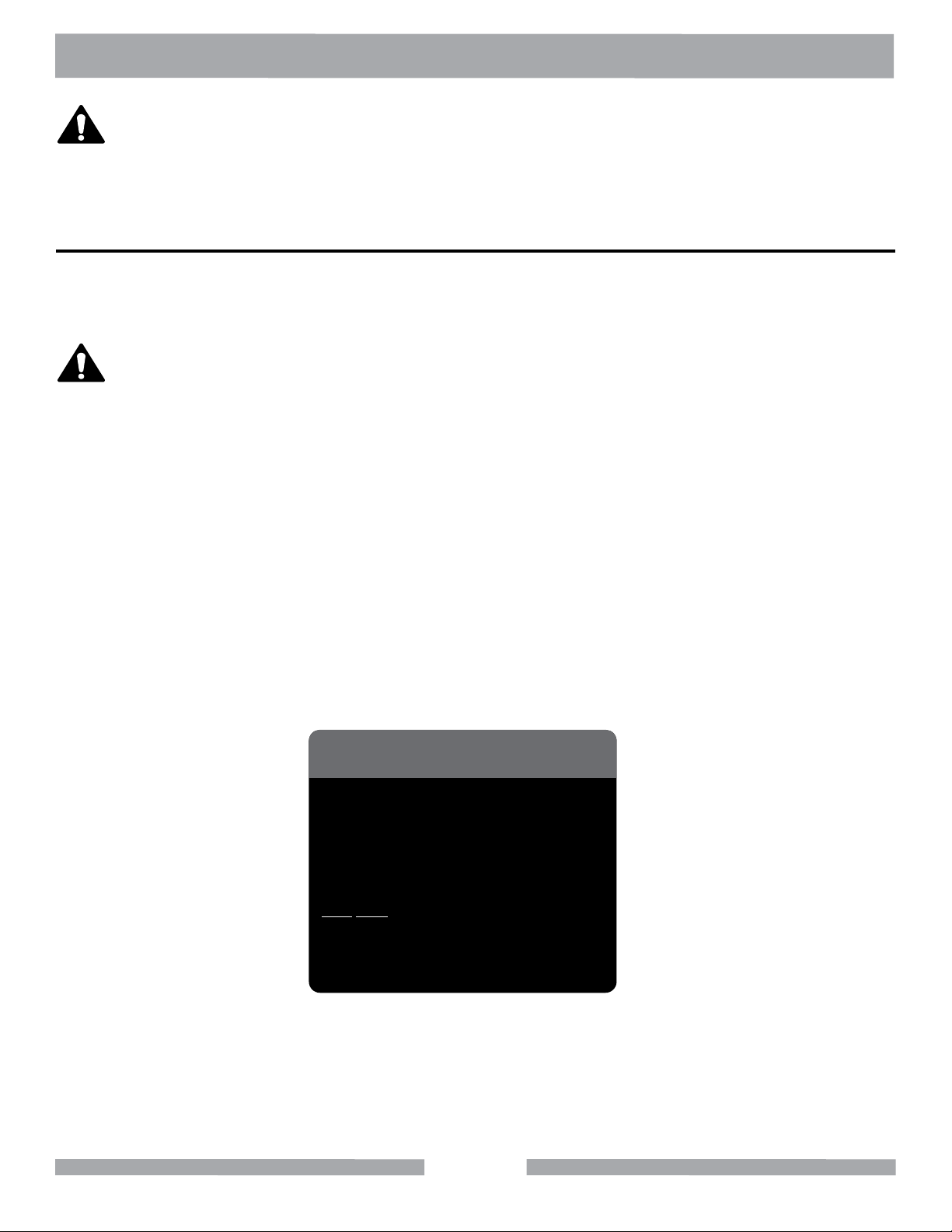
NOTICE
Most Motor Problems are caused by improper
voltage and extension cords. Cord should be
one-piece and short as possible. Cord
selection should match the following table.
1-2 H.P.
115v 230v
25’
100’
50’
150’
75’
250’
Max. Cord Length
Max. Cord Length
Max. Cord Length
No. 12 Wire
No. 10 Wire
No. 8 Wire
7
Page 8
TRACK RAIL SAW SAFETY
RULES FOR SAFE OPERATION
DANGER
Failure to follow instructions in this manual may lead to serious injury or even death! This equipment is
to be operated by trained and qualied personnel only! This equipment is for industrial use only.
The following safety guidelines should always be used when operating the MK-2000 Electric Saw.
GENERAL SAFETY
•DONOT operate or service this equipment before reading this entire manual.
• This equipment should not be operated by persons under 18 years of age.
• NEVER operate this equipment without proper protective clothing, shatterproof glasses, steeltoed
boots and other protective devices required by the job.
• NEVER operate this equipment when not feeling well due to fatigue, illness or taking medicine.
• NEVER operate this equipment under the inuence of drugs or alcohol.
• Whenever necessary, replace nameplate, operation and safety decals when they become difcult
to read.
• ALWAYS check the machine for loose bolts before starting.
•ALWAYS wear proper respiratory (mask) hearing and eye protection
equipment when operating this machine.
• ALWAYS store equipment properly when it is not being used. Equipment should be stored in a clean,
dry location out of the reach of children.
ON / OFF
•NEVER leave the machine unattended. Turn off electric motor when unattended.
• CAUTION must be observed while servicing the machine. Rotating parts can cause injury if contacted.
• Ensure that any electrical extension cord is protected against damage. Always ensure that the
electrical extension cord is not trapped underneath the machine. When using an extension cord,
be sure to use one heavy enough to carry the current your product will draw. An undersized cord
will cause a drop in line voltage that will result in a loss of power and overheating. The Table shown
on page 11 shows the correct AWG size to use depending on cord length and nameplate ampere
rating. If in doubt, use the next heaviest gage. The smaller the gage number, the heavier the cord.
• DONOT allow extension cord to come into contact with water or uids.
• DO NOT spray water onto electric motor.
•NEVER operate the machine in an explosive atmosphere.
• Before starting the machine, check that all guards are in position and correctly tted.
• Keep area around the machine clear of obstructions which could cause persons to fall onto moving parts.
• ALWAYS ensure that the machine is on level ground before using.
• DONOT overreach. Keep proper footing and balance at all times.
8
Page 9
TRACK RAIL SAW SAFETY
•NEVER stand on the tool. Serious injury could occur if a power tool is tipped, or if a cutting tool is
unintentionally contacted.
•Become familiar with the controls of the machine before operating. Know how to stop the machine
quickly in case of emergency.
•ALWAYS secure work. Clamps or a vise should be used to hold work whenever practical. Keep-
ing your hands free to operate a power tool is safer.
•ALWAYS disconnect AC power plug from power source before moving, cleaning or servicing the
machine.
•NEVER leave a tool running unattended. Do not leave a tool until it comes to a complete stop.
ALWAYS turn a power tool OFF when leaving the work area, or when a cut is nished.
•Make sure the OFF/ON power switch on the electric motor is always in the OFF position before
inserting the machine’s power plug into an AC receptacle.
•Operate electric motor only at the specied voltage indicated on the nameplate.
•NEVER disconnect any “emergency or safety devices”. These devices are intended for operator
safety. Disconnection of these devices can cause severe injury, bodily harm or even death! Disconnection of any of these devices will void all warranties.
•Unauthorized equipment modications will void all warranties. Manufacturer does not assume respon-
sibility for any accident due to equipment modications.
•NEVER use accessories or attachments, which are not recommended by MK Diamond for this
equipment. Damage to the equipment and/or injury to user may result.
• Replace damaged cutting blade before operating.
• NEVER try to stop a moving blade with your hand.
WARNING
NEVER use this machine with any cutter designed for wood working.
MAINTENANCE SAFETY
•NEVER lubricate components or attempt service on a running machine.
•Keep the machinery in proper running condition.
•Before using a power tool, check for damaged parts. A guard or any other part that is damage
should be carefully checked to determine if it would operate properly and perform its intended
function. Always check moving parts for proper alignment or binding. Check for broken parts and
mountings and all other conditions that may affect the operation of the power tool. A guard, or any
damaged part, should be properly repaired or replaced.
SAW SAFETY
WARNING
•Wear eye protection.
•Disconnect saw before servicing, when changing cutting blades and cleaning.
•Replace damaged cutting blade before operation.
•Remove adjusting keys and wrenches.
9
Page 10
TRAIL RACK SAW SAFETY
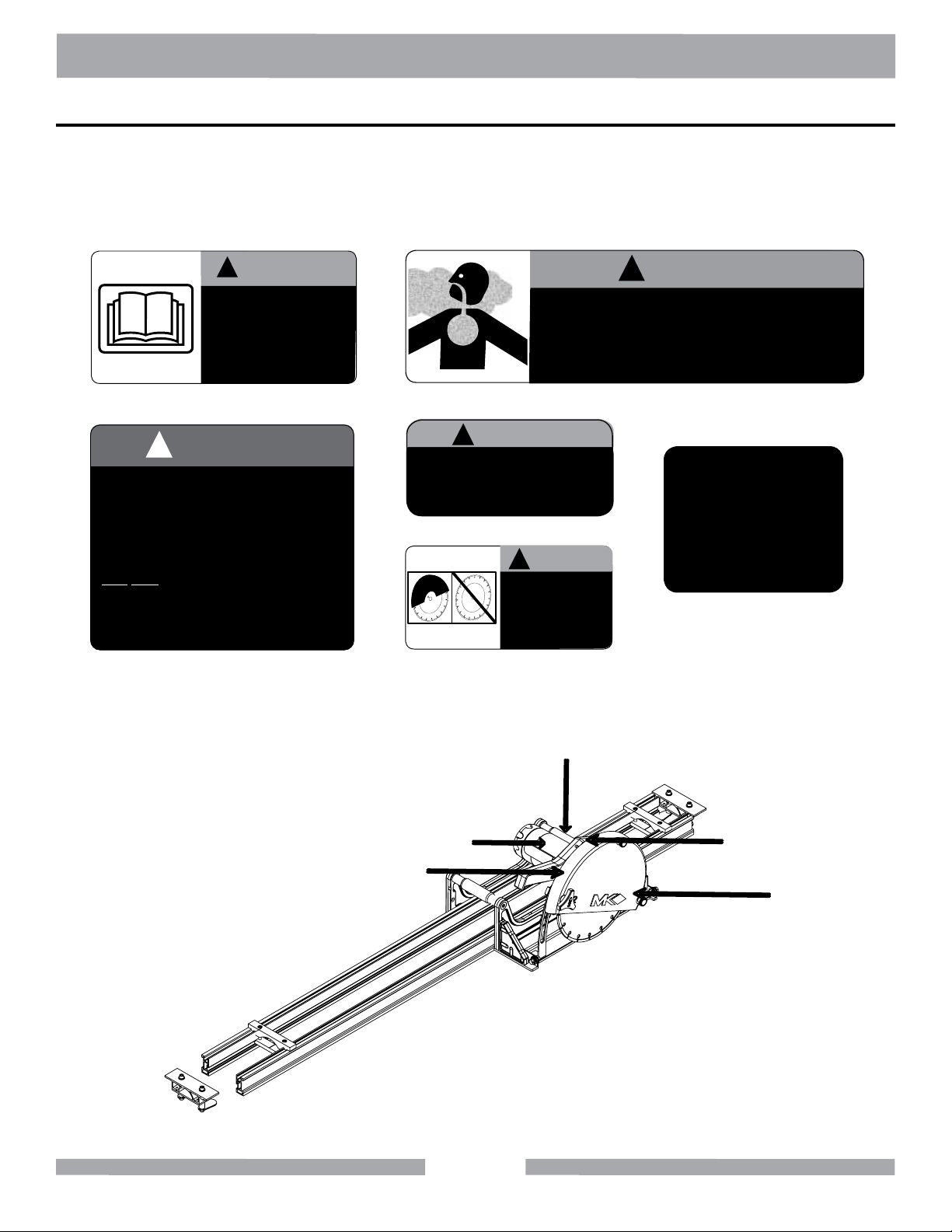
OPERATION & SAFETY DECALS
The MK Diamond Track Rail Saw is equipped with a number of safety decals. These decals are provided for operator safety and maintenance information. The illustration below also shows the location
of these decals. Should any of these operation or safety decals become unreadable, replacements
can be obtained by calling (800) 262-1575.
WARNING
!
!
WARNING
DO NOT operate
this equipment
before reading
the owners’
manual!
Decal A Decal B
!
NOTICE
Most Motor Problems are caused by improper
voltage and extension cords. Cord should be
one-piece and short as possible. Cord
selection should match the following table.
1-2 H.P.
115v 230v
25’
100’
50’
150’
75’
250’
Max. Cord Length
Max. Cord Length
Max. Cord Length
No. 12 Wire
No. 10 Wire
No. 8 Wire
Decal C
Figure 1. MK Diamond Track Rail Saw Safety Decal Sheet, Part No. 166011
Grinding/cutting/drilling of masonry, concrete, metal and other materials with silica in
their composition may give off dust or mists containing crystalline silica. Silica is a basic
component of sand, quartz, brick clay, granite and numerous other minerals and rocks.
Repeated and/or substantial inhalation of airborne crystalline silica can cause serious
or fatal respiratory diseases, including silicosis. In addition,California and some other
authorities have listed respirable crystalline silica as a substance known to cause cancer.
CAUTION
!
This saw is to be used
with a Ground Fault
Circuit Interrupter.
Decal D
CAUTION
!
DO NOT
operate without
guards in place.
Decal E
C
FOR INFORMATION ON
SERVICE OR
WARRANTY
PLEASE CALL
1-800-474-5594
Decal F
A
B
D & F
(behind)
E
10
Page 11
TRACK RAIL SAW PRODUCT SPECIFICATIONS
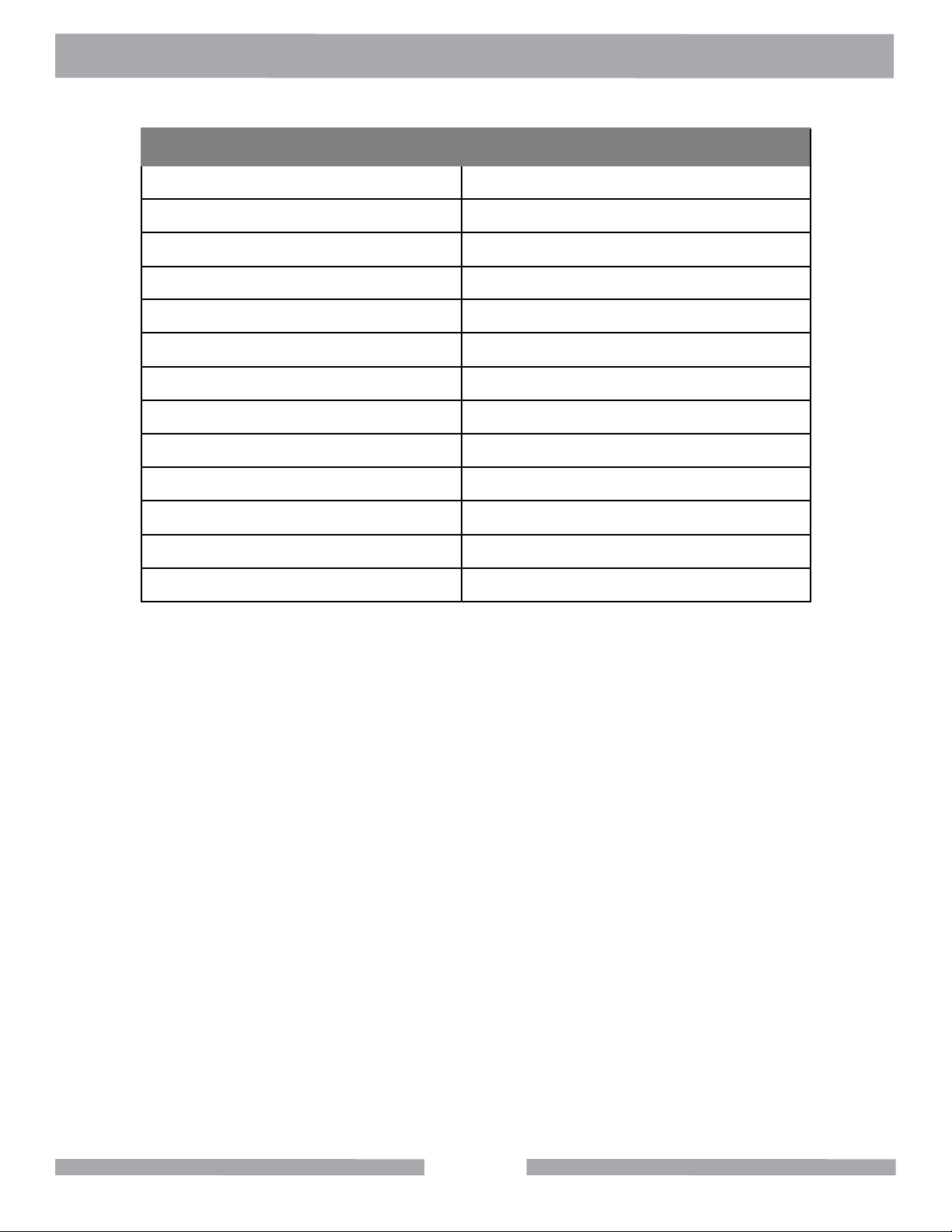
TrackRailSawSpecications
Model 166110
Motor 115V 50/60 Hz
Amps 13
Horsepower 1-3/4 HP
Blade RPM 3,500
Blade Capacity 12” (254 mm)
Arbor Size 1” (25.4 mm)
Standard Length of Cut 130” (3,202mm)
Maximum Depth of Cut 2-7/8” (73mm)
Depth of Cut at 45º 2-1/4 (57mm)
Weight 95 lbs. (43kgs.)
Dimensions(LxWxH)-inches 144” x 16” x 13”
Dimensions(LxWxH)-millimeters 3,658 x 406 x 330
• Adjustable height plunge-cutting head
• Lightweight precision extruded aluminum rails provide accurate and even tracking during all
cutting operations
• Rails have replaceable slip-on pads to protect material surface from scratches
• Precision, maintenance-free bearings provide smooth and reliable tracking of the cutting head
• Replaceable dust lter
• Valve controlled water feed
• 72” 115V standard U-ground electrical cord
• Saw comes complete with two sets of 72” track, track connector plate, 12” blade capacity cutting
head, two hold-down clamps and standard garden hose water connector
• Additional rails for extending cutting capacity sold separately
11
Page 12

TRACK RAIL SAW SET-UP
RailAssembly
1. Lay Rails (A & B) on a at and leveled surface.
2. Align ends of Rails.
3. Slide Parallel Rail Support Brackets (C) from both ends of rail.
4. Tighten screws until Brackets hold Rails rmly in place (D).
5. Repeat Step 1 through 4 if a length of more than 6 feet is needed.
D
D
B
A
C
C
12
Page 13

TRACK RAIL SAW SET-UP
RailAssemblyConnector
The rail connector assembly is required to hold two Rail Assemblies together.
1. Slide the Rail Assembly (A) into the Connector Plate Assembly (B).
2. Tighten screws (C) lightly until connector plate is rmly seated.
3. Slide the other half of the Rail Assembly (D) into the Rail Connector Assembly (B).
4. Fully tighten screws.
A
D
C
D
B
A
13
Page 14

TRACK RAIL SAW SET-UP
CuttingHeadAssembly
The Cutting Head Assembly is pre-assembled and aligned at the factory.
WARNING
Ensure that the power is disconnected before installing the Cutting Head Assembly to Rails.
1. Place the Rail Assembly (B) on slab.
2. Slide the Cutting Head Assembly (A) until the Carrier Wheels (C) are over Rail Assembly (B).
3. Move the Cutting Head Assembly along the Rail Assembly with a sliding motion.
C
A
B
14
Page 15

TRACK RAIL SAW SET-UP
MaterialClamps&Alignment
WARNING
Ensure that the electrical cord is not connected before assembling and aligning material clamps.
1. Position Saw Assembly (A) on the slab. The inner side of the blade is approximately 6.25 inches
from the top edge of the aluminum rail.
2. Slide the Material Clamps from both ends of the Rail Assembly until the Clamp Foot (B) is
underneath the slab.
3. Tighten screws (C) until the Saw Assembly is secured to the slab without any side movement.
4. To realign the Rail Assembly, slightly loosen the Material Clamps. Realign the Rail Assembly by
tapping the ends of the Rail Assembly.
5. Repeat Steps 3 and 4 if realignment is necessary.
C
A
B
15
Page 16

TRACK RAIL SAW SET-UP
HoseSet-Up
1. Connect Plastic Fitting (A) to Nipple (B).
2. Connect Hose Fitting (C) to Water Hose.
A
B
C
16
Page 17

TRACK RAIL SAW OPERATION
CAUTION
Always use a Grounded Fault Circuit Interrupter (GFCI) with this saw.
PlungeCuttingfora90˚Cut
1. Loosen the Tri-Knob (A). Raise the blade to the highest position and move the Saw Assembly
to the beginning of the cut.
2. Adjust the Valve (B) for the desired amount of water ow.
3. Depress motor switch and lower the blade slowly into the material.
4. Tighten the Tri-Knob (A) once the blade cuts through the material. Follow the direction of the cut.
A
B
17
Page 18

TRACK RAIL SAW OPERATION
Plunge Cutting for a Miter Cut
1. Loosen the Round Knob (A) and adjust the blade to the desired angle (0-45 degrees). Tighten
the Round Knob. Recheck the set angle along the entire rail system.
2. Loosen the Tri-Knob (B). Raise the blade to the highest position and move the Saw Assembly
to the beginning of the cut.
3. Adjust the Valve (C) for the desired amount of water ow.
4. Depress motor switch and lower the blade slowly into the material.
5. Tighten the Tri-Knob (B) once the blade cuts through the material. Follow the direction of the cut.
B
C
A
18
Page 19

TRACK RAIL SAW MAINTENANCE
WARNING
Always disconnect the unit from the power supply.
Blade Replacement
1. Remove knobs on outer blade guard.
2. Remove the Blade Guard.
3. Use the open wrenches provided with this unit. Place wrench (A) over the ats on blade shaft
(located on the inner side of the blade). Hold the wrench stationary. Place wrench (B) on the
Hex Screw at the end of the blade shaft. Turn wrench (B) counter-clockwise to remove the screw.
4. Replace the blade and ensure that the blade is oriented with the arrow in a counter clockwise
position. Tighten the screw clockwise to secure the new blade.
5. Rotate the blade by hand to check it for tightness.
INNER GUARD
BLADE
T
U
R
N
A
19
B
Page 20

TRACK RAIL SAW MAINTENANCE
Filter Replacement
1. Pull Filter Cap (A) off.
2. Replace Filter.
3. Snap Filter Cap back on.
A
20
Page 21

TRACK RAIL SAW MAINTENANCE
WARNING
Disconnect the unit from the power supply.
Roller Wheel Replacement
1. Remove the Hex Screws (A) and Round Knob (B).
2. Remove Motor and Blade Guard Assembly from the Carrier Assembly.
3. Remove Carrier Assembly from the Rail Assembly. Place the Carrier Assembly on a at and
level surface.
A
A
B
21
Page 22

TRACK RAIL SAW MAINTENANCE
Roller Wheel Replacement Continued
1. Unscrew the wheel(s) with a 3/16 hex key. Ensure that the eccentric bushings (A) and straight
bushings (C), located in the middle of each carrier casting, do not move.
2. Install new wheels by screwing into bushings.
3. Slide the Carrier Assembly back in the rail to check for wheel alignment.
4. If carrier assembly does not line up with rails, loosen set screw(s) (B) located on the bottom of
carrier legs.
5. Align straight bushing(s) (C) so groove on wheel is centered on rail rib. Hold bushing in place
while tightening set screw. DO NOT FULLY TIGHTEN AT THIS TIME.
A
C
B
C
A
C
22
Page 23

TRACK RAIL SAW MAINTENANCE
Roller Wheel Replacement Continued
1. Position eccentric bushing(s) (A) until the groove on the wheel lines up with the center of the
rail rib. Turn the eccentric bushing(s) (A) until the radial groove of the wheel touches lightly
with the top of the rail rib. Hold the eccentric bushing(s) stationary while tightening down set
screw(s) (B) lightly. Groove aligns with center of upper rail rib. Turn eccentric bushing until wheel
groove lightly contacts upper rail rib. Hold eccentric bushing in place while tightening set screws.
DO NOT FULLY TIGHTEN AT THE TIME.
2. Repeat Steps 7 through 10, if necessary.
3. Tighten all set screws (B).
4. Reinstall the motor and blade guard assembly.
5. Recheck for wheel alignment and smoothness of travel.
A
B
B
23
Page 24

TRACK RAIL SAW PARTS LIST
FinalAssembly
24
Page 25

TRACK RAIL SAW PARTS LIST
FinalAssembly
ITEM
NO.
1 FITTING, PLASTIC, 1/4 FNPT X 1/4 BARB 128397 3
2 HOSE, VINYL, 3/8 X 1/4 X 6 FT 132951 1
3 SCREW, PAN HD SELF TP10-24 X 3/8 151262 2
4 FITTING, HOSE, 1/4 MNPT 152525 1
5 GFCI, 120V, 15A 152610 1
6 NIPPLE, 1/4 NPT X CLOSE, BRASS 159905 1
7 RAIL, TRACK SAW 164926 4
8 FOOT, RAIL 164944 4
9 CLAMP, RAIL SAW MATERIAL 165113 2
10 ASSY, RAIL CONNECTOR PLATE 165268 1
11 ASSY, PARALLEL RAIL SUPPORT BRACKET 165269 4
12 BRACKET, WATER VALVE 165478 1
13 ASSY, BLADE GUARD 165499 1
14 ASSY, MAIN CARRIER 165500 1
15 ASSY, CUTTING HEAD 165501 1
DESCRIPTION
PART OR
IDENTIFYING NO.
QTY.
REQ.
16 HOSE, 3/8 X 1/4 X 10” 165506 1
17 BLADE, 12” 165921 1
18 VALVE, BALL, 1/4”M TO 1/4”F 231248 1
25
Page 26

TRACK RAIL SAW PARTS LIST
MainCarrierAssembly
26
Page 27

TRACK RAIL SAW PARTS LIST
MainCarrierAssembly
ITEM
NO.
1 WHEEL, CONVEYOR CART 133090 6
2 WASHER, 3/8 SAE FLAT 150923 5
3 WASHER, 3/8 SPLIT LOCK 150925 2
4 WASHER, 5/16 SPLIT LOCK 151747 4
5 NUT, 3/8-16 HEX CENTERLOCK 153522 2
6 SCREW, 3/8-16 X 3/4 HEX HEAD CAP 153527 2
7 SCREW, 1/4-20 X 3/4 FLAT HEAD PHILLIPS MACHINE 154657 6
8 KNOB, BALL, 2”, 3/8-16 INSERT 158519 1
9 SCREW, 3/8-16 X 3/8 SOCKET HEAD SET, CUP POINT 160713 6
10 BASE, INNER PIVOT 164923 1
11 BASE, TRACK RAIL SAW PIVOT 164925 1
12 SUPPORT, TRACK RAIL CROSS 164931 2
13 AXLE, CONVEYOR WHEEL 164932 4
14 AXLE, ADJ CONVEYOR WHEEL 164933 2
15 SCREW, 1/4-20 X 3/4 FLAT HEAD PHILLIPS MACHINE 165120 2
16 SCREW, 1/2-13 X 1-1/4 FLAT HEAD 165164 4
DESCRIPTION
PART OR
IDENTIFYING NO.
QTY.
REQ.
17 GUSSET (COMP) 166112 1
18 CARRIER, CART WHEEL (COMP) 166114 2
19 GRIP, HANDLE 229413 2
27
Page 28

TRACK RAIL SAW PARTS LIST
CuttingHeadAssembly
28
Page 29

TRACK RAIL SAW PARTS LIST
CuttingHeadAssembly
ITEM
NO.
1 SCREW, 5/16-18 X 1 HEX HEAD MACHINE 151743 2
2 WASHER, 5/16 SPLIT LOCK 151747 2
3 WASHER, 5/16 SAE FLAT 151754 2
4 LABEL, CAUTION, SAFETY 155576 1
5 FILTER, MOTOR 157729 1
6 CAP, MOTOR 157877 1
7 SPACER, NYLON 157878 1
8 SPACE, CAP SCREW 157879 2
9 FLANGE, Ø 3.0 INNER 158106 1
10 SCREW, #8 X 1-1/2 FLAT HD PHIL 158157 2
11 ASSY, MOTOR, 115V/3A 160251 1
12 LABEL, WARNING, SILICA, PROP 65 164202 1
13 PIN, PIVOT 164934 1
14 SPRING, 70’ TORSION 165272 1
DESCRIPTION
PART OR
IDENTIFYING NO.
QTY.
REQ.
29
Page 30

TRACK RAIL SAW PARTS LIST
BladeGuardAssembly
ITEM
NO.
1 WASHER, 3/8 SAE FLAT 150923 1
2 WASHER, 1/4 SAE FLAT 151915 2
3 KNOB, TRI PLASTIC, 3/8-16X2-1/4 56770-04 1
4 TAG, SERIAL #, BLANK 157500 1
5 DRIVE SCREW, #7 X 5/16 ROUND HEAD 157849 2
6 SCREW, HEX HEAD CAP, M6 X 1 X 20MM 158158 4
7 WASHER, SPLIT LOCK, M6 158159 4
8 MANIFOLD, WATER 159854 1
9 NUT, 3/8-16 HEX 159863 1
10 NUT, ROUNDED T-SLOT 164945 1
11 KNOB, 1/4-20X2 ROUND 165163 2
12 GUARD, BLADE (COMP) 166109 1
13 GUARD, INNER BLADE (COMP) 166111 1
DESCRIPTION
PART OR
IDENTIFYING NO.
30
QTY.
REQ.
Page 31

TRACK RAIL SAW PARTS LIST
Parallel Rail Support Bracket
ITEM
NO.
1 CLAMP, UPPER RAIL 164939 1
2 CLAMP, LOWER RAIL (COMP) 164942 1
3 SCREW, 5/16-18X2 SOCKET HEAD CAP 165165 2
DESCRIPTION
PART OR
IDENTIFYING NO.
31
QTY.
REQ.
Page 32

TRACK RAIL SAW PARTS LIST
Rail Connector Plate
ITEM
NO.
1 PLATE, RAIL CONNECTOR 164936 1
2 SHOE, CONNECTOR (COMP) 164938 6
3 SCREW, 5/16-18X2 SOCKET HEAD CAP 165165 6
DESCRIPTION
PART OR
IDENTIFYING NO.
32
QTY.
REQ.
Page 33

TRACK RAIL SAW PARTS LIST
Rail Saw Material Clamp
ITEM
NO.
1 WASHER, 5/16 SAE FLAT 151754 2
2 SCREW, 5/16-18X1/2 SOCKET HEAD CAP 156139 2
3 BASE, MATERIAL CLAMP 165114 1
4 PLATE, MATERIAL CLAMP SUPPORT 165115 1
5 STAND-OFF, THREADED 165116 2
6 FOOT, MATERAL CLAMP 165117 2
7 SCREW, 10-24 X 3/4 FLAT HEAD PHILLIPS MACHINE 165121 4
8 SCREW, 5/16-18 X 2 SOCKET CAP 165243 2
DESCRIPTION
PART OR
IDENTIFYING NO.
33
QTY.
REQ.
Page 34

ORDERING INFORMATION
You may order MK Diamond products through your local MK Diamond distributor or, you may order
direct from MK Diamond.
When ordering direct from MK Diamond, please have the following information ready before calling:
• The Model Number of the saw
• The Serial Number of the saw
• Where the saw was purchased and when
• The Part Number for the part(s) being ordered
• The Part Description for the part(s) being ordered
NOTE: There is a $25.00 minimum order when ordering direct from MK Diamond. A $5.00 charge will
be added to orders having a net billing value under $50.00. All purchases must be made using VISA,
MasterCard or American Express.
All parts may be ordered by calling toll free to – 800 421-5830 or 310 539-5221 and asking for
Customer Service. For technical questions, call – 800 474-5594.
RETURN MATERIALS POLICY
To expedite the service relative to the return of a product purchased through MK Diamond, please
observe the following:
NOTE: When returning all items, they must have been purchased within the previous twelve (12)
months.
• Have the Model Number of the saw
• Have the Serial Number of the saw
• Have the location of where the saw was purchased
• Have the date when the saw was purchased
• Contact Customer Service for approval to return the item(s)
• Obtain a Returned Goods Number (RGA) authorizing the return
• Follow the packaging instructions in the following section
• Ensure your item(s) are prepaid to the destination
For returned items, call toll free to – 800 421-5830 or 310 539-5221 and ask for Customer Service.
For technical questions, call – 800 474-5594 or 310 257-2845.
PACKAGING INSTRUCTIONS
• Remove the Cutting Head and Support Angle Assembly
• Dry the saw before shipping
• When packing, include the following: Saw, Diamond Blade, Blade Guard and Support Angle
Assembly and Adjustable Cutting Guide (Other Accessories are not required)
• Package the unit in its original container or one of comparable size (do not ship the unit partially
exposed)
• Ensure all parts are secured in the packaging to prevent moving
AUTHORIZED SERVICE CENTERS
For quicker repair time, you may contact MK Diamond Customer Service, toll free, at 800 421-5830
or 310 539-5221 for the Authorized Service Center closest too you or visit our web site at
www.mkdiamond.com. For technical questions, call – 800 474-5594.
34
Page 35

CONTACT:
Please contact MK Diamond Products, Inc. Customer Service Department with any questions you
might have regarding distributors, parts or service.
Telephone: (800) 421-5830
Fax: (310) 539-5158
E-mail: Customer_Service@MKDiamond.com
Customer Service Hours: Monday through Friday, 6AM-4PM PST
MKDiamondProducts,Inc.
1315 Storm Parkway
Torrance, CA 90501
MK DIAMOND PRODUCTS, INC. LIMITED WARRANTY
MK DIAMOND PRODUCTS, INC. will guarantee every machine they build, to be free from defects in
material and workmanship for (1) one year from date of purchase. The obligation of MK DIAMOND
PRODUCTS, INC. under this warranty is limited to the repair or replacement of any parts which,
under normal use, prove to be defective in material or workmanship. The parts involved or the unit
in question should be returned to MK DIAMOND PRODUCTS, INC. or to a point designated by us,
transportation prepaid.
This warranty does not obligate us to bear the cost of labor or transportation charges in connection
with replacement or repair of defective parts. Likewise, it shall NOT apply to any unit which has been
subjected to misuse, neglect or accident. This warranty does NOT apply to any machine which has
been repaired or altered outside our factory.
This warranty does NOT obligate MK DIAMOND PRODUCTS, INC., with respect to items not of our
manufacture, such as engines, motors, hydraulics, etc., which are subject to their own guarantees and
warranties.
We shall in no event be liable for consequential damages or contingent liabilities arising out of failure
of any equipment or parts to operate properly.
© COPYRIGHT 2012, MK DIAMOND PRODUCTS, INC. ALL RIGHTS RESERVED.
The MK Diamond logo is a registered trademark of MK Diamond Products, Inc. and may not be used,
reproduced, or altered without written permission. All other trademarks are the property of their respective owners and used with permission.
MK Diamond may have patents, patent applications, trade marks, copyrights of other intellectual
property right covering this product in this document.
This manual MUST accompany the equipment at all times. This manual is considered a permanent
part of the equipment and should remain with the unit if resold.
The information and specications included in this publication were in effect at the time of approval for
printing.
35
Page 36

MK DIAMOND TRACK RAIL SAW
OPERATION & PARTS MANUAL
MK Diamond Products, Inc.
1315 Storm Parkway
Torrance, CA 90501
Toll-Free: (800) 421-5830
Phone: (310) 539-5221
Fax: (310) 539-5158
www.mkdiamond.com
 Loading...